EP4560114A1 - Piston ring seal - Google Patents
Piston ring seal Download PDFInfo
- Publication number
- EP4560114A1 EP4560114A1 EP24214908.6A EP24214908A EP4560114A1 EP 4560114 A1 EP4560114 A1 EP 4560114A1 EP 24214908 A EP24214908 A EP 24214908A EP 4560114 A1 EP4560114 A1 EP 4560114A1
- Authority
- EP
- European Patent Office
- Prior art keywords
- piston ring
- axially
- facing side
- circumferential
- edges
- Prior art date
- Legal status (The legal status is an assumption and is not a legal conclusion. Google has not performed a legal analysis and makes no representation as to the accuracy of the status listed.)
- Pending
Links
Images

Classifications
-
- F—MECHANICAL ENGINEERING; LIGHTING; HEATING; WEAPONS; BLASTING
- F01—MACHINES OR ENGINES IN GENERAL; ENGINE PLANTS IN GENERAL; STEAM ENGINES
- F01D—NON-POSITIVE DISPLACEMENT MACHINES OR ENGINES, e.g. STEAM TURBINES
- F01D11/00—Preventing or minimising internal leakage of working-fluid, e.g. between stages
- F01D11/005—Sealing means between non relatively rotating elements
-
- F—MECHANICAL ENGINEERING; LIGHTING; HEATING; WEAPONS; BLASTING
- F01—MACHINES OR ENGINES IN GENERAL; ENGINE PLANTS IN GENERAL; STEAM ENGINES
- F01D—NON-POSITIVE DISPLACEMENT MACHINES OR ENGINES, e.g. STEAM TURBINES
- F01D11/00—Preventing or minimising internal leakage of working-fluid, e.g. between stages
- F01D11/003—Preventing or minimising internal leakage of working-fluid, e.g. between stages by packing rings; Mechanical seals
-
- F—MECHANICAL ENGINEERING; LIGHTING; HEATING; WEAPONS; BLASTING
- F02—COMBUSTION ENGINES; HOT-GAS OR COMBUSTION-PRODUCT ENGINE PLANTS
- F02C—GAS-TURBINE PLANTS; AIR INTAKES FOR JET-PROPULSION PLANTS; CONTROLLING FUEL SUPPLY IN AIR-BREATHING JET-PROPULSION PLANTS
- F02C7/00—Features, components parts, details or accessories, not provided for in, or of interest apart form groups F02C1/00 - F02C6/00; Air intakes for jet-propulsion plants
- F02C7/28—Arrangement of seals
-
- F—MECHANICAL ENGINEERING; LIGHTING; HEATING; WEAPONS; BLASTING
- F16—ENGINEERING ELEMENTS AND UNITS; GENERAL MEASURES FOR PRODUCING AND MAINTAINING EFFECTIVE FUNCTIONING OF MACHINES OR INSTALLATIONS; THERMAL INSULATION IN GENERAL
- F16J—PISTONS; CYLINDERS; SEALINGS
- F16J15/00—Sealings
- F16J15/16—Sealings between relatively-moving surfaces
- F16J15/32—Sealings between relatively-moving surfaces with elastic sealings, e.g. O-rings
- F16J15/3268—Mounting of sealing rings
- F16J15/3272—Mounting of sealing rings the rings having a break or opening, e.g. to enable mounting on a shaft otherwise than from a shaft end
-
- F—MECHANICAL ENGINEERING; LIGHTING; HEATING; WEAPONS; BLASTING
- F05—INDEXING SCHEMES RELATING TO ENGINES OR PUMPS IN VARIOUS SUBCLASSES OF CLASSES F01-F04
- F05D—INDEXING SCHEME FOR ASPECTS RELATING TO NON-POSITIVE-DISPLACEMENT MACHINES OR ENGINES, GAS-TURBINES OR JET-PROPULSION PLANTS
- F05D2240/00—Components
- F05D2240/55—Seals
- F05D2240/58—Piston ring seals
Definitions
- Exemplary embodiments of the present disclosure pertain to the art of gas turbine engines, and in particular to piston ring seals utilized in gas turbine engines.
- Piston ring seals are utilized in certain locations in gas turbine engines to prevent undesired leakage of airflow into or out of the engine flowpath and/or other engine cavities.
- Pressure effects, thermo-mechanical deflections, and vibratory effects drive interactions between the piston ring seals and mating components axially and radially adjacent to the piston ring seals.
- edges of the piston ring seals contacting the mating parts and interacting therewith via the methods mentioned previously results in increased wear at the piston ring seal to mating part interface. This is exacerbated by the fact that the edges of the joint by design are located at the free ends of the seal, which respond more to vibrations and where the thermal expansion of the ring/mating parts is absorbed.
- a piston ring seal arrangement of a gas turbine engine includes a piston ring having a circumferentially split ring configuration having a first axially-facing side and a second axially-facing side opposite the first axially facing side.
- the piston ring includes a first circumferential end circumferentially overlapping a second circumferential end.
- the piston ring is installed into a groove in a mating component.
- the first circumferential end and the second circumferential end define a plurality of edges on the first axially-facing side and the second axially-facing side.
- the first axially-facing side includes fewer edges than the second axially-facing side, and an operating pressure acting on the piston ring is greater at the second axially-facing side than at the first axially-facing side.
- a first end pocket is formed in the first circumferential end
- a second end finger is formed in the second circumferential end and configured to be received in the first end pocket
- the first end pocket is defined at least in part by two or more of a first end circumferential surface, a first end axial surface and a first end radial surface.
- the first end circumferential surface defines a circumferential length of the first end pocket
- the first end axial surface defines an axial width of the first end pocket
- the first end radial surface defines a radial depth of the first end pocket
- the second end finger is defined at least in part by two or more of a second end radial surface defining a radial height of the second end finger, a second end axial surface defining an axial length of the second end finger, and a second end circumferential surface defining a circumferential length of the second end finger.
- a convex radius is formed at at least one edge of the plurality of edges.
- a convex radius is formed at two or more edges of the plurality of edges, and where the convex radius varies at the two or more edges.
- a gas turbine engine in another aspect of the present invention, includes a combustor configured to combust a mixture of air and fuel, a turbine driven by combustion products flowed from the combustor, and at least one piston ring seal arrangement.
- the piston ring seal arrangement includes a piston ring having a circumferentially split ring configuration having a first axially-facing side and a second axially-facing side opposite the first axially facing side.
- the piston ring includes a first circumferential end circumferentially overlapping a second circumferential end.
- a mating component has a groove into which the piston ring is installed.
- the first circumferential end and the second circumferential end define a plurality of edges on the first axially-facing side and the second axially-facing side.
- the first axially-facing side includes fewer edges than the second axially-facing side, and an operating pressure acting on the piston ring is greater at the second axially-facing side than at the first axially-facing side.
- a first end pocket is formed in the first circumferential end
- a second end finger is formed in the second circumferential end and configured to be received in the first end pocket
- the first end pocket is defined at least in part by two or more of a first end circumferential surface, a first end axial surface and a first end radial surface.
- the first end circumferential surface defines a circumferential length of the first end pocket
- the first end axial surface defines an axial width of the first end pocket
- the first end radial surface defines a radial depth of the first end pocket
- the second end finger is defined at least in part by two or more of a second end radial surface defining a radial height of the second end finger, a second end axial surface defining an axial length of the second end finger, and a second end circumferential surface defining a circumferential length of the second end finger.
- a convex radius is formed at two or more edges of the plurality of edges, and where the convex radius varies at the two or more edges.
- the piston ring is configured to seal between a casing element and a vane of the gas turbine engine.
- a vane and case element assembly of a gas turbine engine includes a vane, a case element positioned radially adjacent to the vane, and a piston ring seal positioned to seal between the vane and the case element.
- the piston ring seal includes a piston ring having a circumferentially split ring configuration having a first axially-facing side and a second axially-facing side opposite the first axially facing side.
- the piston ring includes a first circumferential end circumferentially overlapping a second circumferential end. The piston ring is installed into a case element groove in the case element.
- the first circumferential end and the second circumferential end define a plurality of edges on the first axially-facing side and the second axially-facing side, and the first axially-facing side includes fewer edges than the second axially-facing side.
- An operating pressure acting on the piston ring is greater at the second axially-facing side than at the first axially-facing side.
- a first end pocket is formed in the first circumferential end
- a second end finger is formed in the second circumferential end and configured to be received in the first end pocket
- the first end pocket is defined at least in part by two or more of a first end circumferential surface, a first end axial surface and a first end radial surface.
- a convex radius is formed at at least one edge of the plurality of edges.
- a convex radius is formed at two or more edges of the plurality of edges, and where the convex radius varies at the two or more edges.
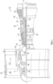
- FIG. 1 schematically illustrates a gas turbine engine 20.
- the gas turbine engine 20 is disclosed herein as a two-spool turbofan that generally incorporates a fan section 22, a compressor section 24, a combustor section 26 and a turbine section 28.
- Alternative engines might include other systems or features.
- the fan section 22 drives air along a bypass flow path B in a bypass duct, while the compressor section 24 drives air along a core flow path C for compression and communication into the combustor section 26 then expansion through the turbine section 28.
- FIG. 1 schematically illustrates a gas turbine engine 20.
- the gas turbine engine 20 is disclosed herein as a two-spool turbofan that generally incorporates a fan section 22, a compressor section 24, a combustor section 26 and a turbine section 28.
- Alternative engines might include other systems or features.
- the fan section 22 drives air along a bypass flow path B in a bypass duct
- the compressor section 24 drives air along a core flow path C for compression and communication into the combustor section 26
- the exemplary engine 20 generally includes a low speed spool 30 and a high speed spool 32 mounted for rotation about an engine central longitudinal axis A relative to an engine static structure 36 via several bearing systems 38. It should be understood that various bearing systems 38 at various locations may alternatively or additionally be provided, and the location of bearing systems 38 may be varied as appropriate to the application.
- the low speed spool 30 generally includes an inner shaft 40 that interconnects a fan 42, a low pressure compressor 44 and a low pressure turbine 46.
- the inner shaft 40 is connected to the fan 42 through a speed change mechanism, which in exemplary gas turbine engine 20 is illustrated as a geared architecture 48 to drive the fan 42 at a lower speed than the low speed spool 30.
- the high speed spool 32 includes an outer shaft 50 that interconnects a high pressure compressor 52 and high pressure turbine 54.
- a combustor 56 is arranged in exemplary gas turbine 20 between the high pressure compressor 52 and the high pressure turbine 54.
- An engine static structure 36 is arranged generally between the high pressure turbine 54 and the low pressure turbine 46.
- the engine static structure 36 further supports bearing systems 38 in the turbine section 28.
- the inner shaft 40 and the outer shaft 50 are concentric and rotate via bearing systems 38 about the engine central longitudinal axis A which is collinear with their longitudinal axes.
- each of the positions of the fan section 22, compressor section 24, combustor section 26, turbine section 28, and fan drive gear system 48 may be varied.
- gear system 48 may be located aft of combustor section 26 or even aft of turbine section 28, and fan section 22 may be positioned forward or aft of the location of gear system 48.
- the engine 20 in one example is a high-bypass geared aircraft engine.
- the engine 20 bypass ratio is greater than about six (6), with an example embodiment being greater than about ten (10)
- the geared architecture 48 is an epicyclic gear train, such as a planetary gear system or other gear system, with a gear reduction ratio of greater than about 2.3
- the low pressure turbine 46 has a pressure ratio that is greater than about five.
- the engine 20 bypass ratio is greater than about ten (10:1)
- the fan diameter is significantly larger than that of the low pressure compressor 44
- the low pressure turbine 46 has a pressure ratio that is greater than about five 5:1.
- Low pressure turbine 46 pressure ratio is pressure measured prior to inlet of low pressure turbine 46 as related to the pressure at the outlet of the low pressure turbine 46 prior to an exhaust nozzle.
- the geared architecture 48 may be an epicycle gear train, such as a planetary gear system or other gear system, with a gear reduction ratio of greater than about 2.3: 1. It should be understood, however, that the above parameters are only exemplary of one embodiment of a geared architecture engine and that the present disclosure is applicable to other gas turbine engines including direct drive turbofans.
- the fan section 22 of the engine 20 is designed for a particular flight condition--typically cruise at about 0.8Mach and about 35,000 feet (10,688 meters).
- 'TSFC' Thrust Specific Fuel Consumption
- Low fan pressure ratio is the pressure ratio across the fan blade alone, without a Fan Exit Guide Vane (“FEGV”) system.
- the low fan pressure ratio as disclosed herein according to one non-limiting embodiment is less than about 1.45.
- Low corrected fan tip speed is the actual fan tip speed in ft/sec divided by an industry standard temperature correction of [(Tram °R)/(518.7 °R)] 0.5 .
- the "Low corrected fan tip speed” as disclosed herein according to one non-limiting embodiment is less than about 1150 ft/second (350.5 m/sec).
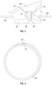
- FIG. 2 illustrates a vane, for example, a turbine vane 60 interface to a case element 62, with a piston ring 64 positioned in a case groove 66 of the case element 62 and interfacing with the turbine vane 60 to seal between the turbine vane 60 and the case element 62.
- flow direction of the airflow along the flowpath is illustrated as 68, with higher cavity pressure 120 at a downstream side 70 of the piston ring 64 and in the case groove 66 than at an upstream side 72 of the piston ring 64.
- This pressure difference urges the piston ring 64 into axial contact with an upstream groove face 74 of the case groove 66 and in some embodiments results in a gap between the piston ring 64 and a downstream groove face 76 opposite the upstream groove face 74.
- the piston ring 64 is further urged in a radial direction into contact with the turbine stator vane 60 to seal to the turbine stator vane 60.
- the piston ring 64 is configured as a split ring having a first circumferential end 78 and a second circumferential end 80.
- the piston ring 64 has a rectangular cross-section.
- the first circumferential end 78 circumferentially overlaps the second circumferential end 80 to define the closed loop piston ring 64.
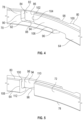
- FIG. 4 and 5 the arrangement of the first circumferential end 78 and the second circumferential end 80 will be described further.
- the downstream side 70 of the piston ring 64 is illustrated in FIG. 4
- the upstream side 72 of the piston ring 64 is illustrated in FIG. 5 .
- the first circumferential end 78 includes a first end pocket 82 defined as an axial and circumferential recess in the first circumferential end 78.
- the first end pocket 82 is at least partially defined by a first end circumferential surface 84, a first end axial surface 86 and a first end radial surface 88, where the first end circumferential surface 84 defines a circumferential length of the first end pocket 82, the first end axial surface 86 defines an axial width of the first end pocket 82, and the first end radial surface 88 defines a radial depth of the first end pocket 82.
- An intersection of the downstream side 70 and the first end circumferential surface 84 defines a first end circumferential edge 90, and an intersection of the downstream side 70 and the first end radial surface 88 defines a first end radial edge 92.
- the second circumferential end 80 includes a second end finger 94 sized and configured to be received in the first end pocket 82.
- the second end finger 94 is defined at least in part by the downstream side 70, a second end radial surface 96 defining a radial height of the second end finger 94, a second end axial surface 98 defining an axial length of the second end finger 94, and a second end circumferential surface 100 defining a circumferential length of the second end finger 94.
- An intersection of the downstream side 70 and a second circumferential end tip 102 defines a second end tip edge 104, and an intersection of the second end radial surface 96 and the downstream side 70 define a second end radial edge 106.
- the second end tip edge 104 is circumferentially spaced apart from the first end circumferential edge 90.
- the upstream side 72 includes a second circumferential edge 108 defined by an intersection of the upstream side 72 and the second end circumferential surface 100. Further, an intersection of a first circumferential end tip 110 and the upstream side 72 defines a first end tip edge 112. In some embodiments, the second circumferential edge 108 is circumferentially spaced apart from the first end tip edge 112.
- orienting the piston ring 64 with the downstream side 70 located at the relatively high pressure side of the seal arrangement urges the upstream side 72 against the upstream groove face 74.
- This orientation of the piston ring 64 is advantageous at least because there are fewer edges urged into contact with the upstream groove face 74, thus reducing wear at the interface of the piston ring 64 to the upstream groove face 74, when compared to configurations where the downstream side 70 is urged into contact with the upstream groove face 74.
- one or more of the edges 90, 92, 104, 106, 108, 112 described herein are crowned, or have a convex radius 114 applied thereto.
- the convex radius 114 may be the same for each of the edges 90, 92, 104, 106, 108, 112, or may vary depending on location of the edges on the piston ring 64.
- the convex radius 114 is applied to one or more of the edges 90, 92, 104, 106, 108, 112 to reduce contact and thereby reduce wear at the interface of the piston ring 64 to the case groove 66.
- surface 116 may include a chamfer as illustrated or alternatively a convex radius 114.
- the radius 114 may be sized relative to a ring width 118 or a ring height 120.
- the radius 114 is in the range of 0.3 - 0.5 times the ring width 118 or is in the range of 0.1 - 0.3 of the ring height 120.
Landscapes
- Engineering & Computer Science (AREA)
- General Engineering & Computer Science (AREA)
- Mechanical Engineering (AREA)
- Chemical & Material Sciences (AREA)
- Combustion & Propulsion (AREA)
- Turbine Rotor Nozzle Sealing (AREA)
Abstract
A piston ring seal arrangement of a gas turbine engine includes a piston ring (64) having a circumferentially split ring configuration having a first axially-facing side (72) and a second axially-facing side (70) opposite the first axially facing side (72). The piston ring (64) includes a first circumferential end (78) circumferentially overlapping a second circumferential end (80). The piston ring (64) is installed into a groove (66) in a mating component (62). The first circumferential end (78) and the second circumferential end (80) define a plurality of edges (90... 112) on the first axially-facing side (72) and the second axially-facing side (70). The first axially-facing side (72) includes fewer edges (90...112) than the second axially-facing side (70), and an operating pressure acting on the piston ring (64) is greater at the second axially-facing side (70) than at the first axially-facing side (72).

Description
- Exemplary embodiments of the present disclosure pertain to the art of gas turbine engines, and in particular to piston ring seals utilized in gas turbine engines.
- Piston ring seals are utilized in certain locations in gas turbine engines to prevent undesired leakage of airflow into or out of the engine flowpath and/or other engine cavities. Pressure effects, thermo-mechanical deflections, and vibratory effects drive interactions between the piston ring seals and mating components axially and radially adjacent to the piston ring seals. In particular, edges of the piston ring seals contacting the mating parts and interacting therewith via the methods mentioned previously results in increased wear at the piston ring seal to mating part interface. This is exacerbated by the fact that the edges of the joint by design are located at the free ends of the seal, which respond more to vibrations and where the thermal expansion of the ring/mating parts is absorbed.
- In an aspect of the present invention, a piston ring seal arrangement of a gas turbine engine includes a piston ring having a circumferentially split ring configuration having a first axially-facing side and a second axially-facing side opposite the first axially facing side. The piston ring includes a first circumferential end circumferentially overlapping a second circumferential end. The piston ring is installed into a groove in a mating component. The first circumferential end and the second circumferential end define a plurality of edges on the first axially-facing side and the second axially-facing side. The first axially-facing side includes fewer edges than the second axially-facing side, and an operating pressure acting on the piston ring is greater at the second axially-facing side than at the first axially-facing side.
- In an embodiment of the above, a first end pocket is formed in the first circumferential end, and a second end finger is formed in the second circumferential end and configured to be received in the first end pocket.
- In an embodiment according to any of the previous embodiments, the first end pocket is defined at least in part by two or more of a first end circumferential surface, a first end axial surface and a first end radial surface.
- In an embodiment according to any of the previous embodiments, the first end circumferential surface defines a circumferential length of the first end pocket, the first end axial surface defines an axial width of the first end pocket, and the first end radial surface defines a radial depth of the first end pocket.
- In an embodiment according to any of the previous embodiments, the second end finger is defined at least in part by two or more of a second end radial surface defining a radial height of the second end finger, a second end axial surface defining an axial length of the second end finger, and a second end circumferential surface defining a circumferential length of the second end finger.
- In an embodiment according to any of the previous embodiments, a convex radius is formed at at least one edge of the plurality of edges.
- In an embodiment according to any of the previous embodiments, a convex radius is formed at two or more edges of the plurality of edges, and where the convex radius varies at the two or more edges.
- In another aspect of the present invention, a gas turbine engine includes a combustor configured to combust a mixture of air and fuel, a turbine driven by combustion products flowed from the combustor, and at least one piston ring seal arrangement. The piston ring seal arrangement includes a piston ring having a circumferentially split ring configuration having a first axially-facing side and a second axially-facing side opposite the first axially facing side. The piston ring includes a first circumferential end circumferentially overlapping a second circumferential end. A mating component has a groove into which the piston ring is installed. The first circumferential end and the second circumferential end define a plurality of edges on the first axially-facing side and the second axially-facing side. The first axially-facing side includes fewer edges than the second axially-facing side, and an operating pressure acting on the piston ring is greater at the second axially-facing side than at the first axially-facing side.
- In an embodiment of the above, a first end pocket is formed in the first circumferential end, and a second end finger is formed in the second circumferential end and configured to be received in the first end pocket.
- In an embodiment according to any of the previous embodiments, the first end pocket is defined at least in part by two or more of a first end circumferential surface, a first end axial surface and a first end radial surface.
- In an embodiment according to any of the previous embodiments, the first end circumferential surface defines a circumferential length of the first end pocket, the first end axial surface defines an axial width of the first end pocket, and the first end radial surface defines a radial depth of the first end pocket.
- In an embodiment according to any of the previous embodiments, the second end finger is defined at least in part by two or more of a second end radial surface defining a radial height of the second end finger, a second end axial surface defining an axial length of the second end finger, and a second end circumferential surface defining a circumferential length of the second end finger.
- In an embodiment according to any of the previous embodiments, a convex radius is formed at at least one edge of the plurality of edges.
- In an embodiment according to any of the previous embodiments, a convex radius is formed at two or more edges of the plurality of edges, and where the convex radius varies at the two or more edges.
- In an embodiment according to any of the previous embodiments, the piston ring is configured to seal between a casing element and a vane of the gas turbine engine.
- In yet another aspect of the present invention, a vane and case element assembly of a gas turbine engine includes a vane, a case element positioned radially adjacent to the vane, and a piston ring seal positioned to seal between the vane and the case element. The piston ring seal includes a piston ring having a circumferentially split ring configuration having a first axially-facing side and a second axially-facing side opposite the first axially facing side. The piston ring includes a first circumferential end circumferentially overlapping a second circumferential end. The piston ring is installed into a case element groove in the case element. The first circumferential end and the second circumferential end define a plurality of edges on the first axially-facing side and the second axially-facing side, and the first axially-facing side includes fewer edges than the second axially-facing side. An operating pressure acting on the piston ring is greater at the second axially-facing side than at the first axially-facing side.
- In an embodiment of the above, a first end pocket is formed in the first circumferential end, and a second end finger is formed in the second circumferential end and configured to be received in the first end pocket.
- In an embodiment according to any of the previous embodiments, the first end pocket is defined at least in part by two or more of a first end circumferential surface, a first end axial surface and a first end radial surface.
- In an embodiment according to any of the previous embodiments, a convex radius is formed at at least one edge of the plurality of edges.
- In an embodiment according to any of the previous embodiments, a convex radius is formed at two or more edges of the plurality of edges, and where the convex radius varies at the two or more edges.
- The following descriptions should not be considered limiting in any way. With reference to the accompanying drawings, like elements are numbered alike:
-
FIG. 1 is a partial cross-sectional view of a gas turbine engine; -
FIG. 2 is a partial cross-sectional view of a vane and case arrangement having a piston ring seal; -
FIG. 3 is a perspective view of an exemplary embodiment of a piston ring seal; -
FIG. 4 is a first partial view of an exemplary end portion of a piston ring seal; -
FIG. 5 is a second partial view of an exemplary end portion of a piston ring seal; and -
FIG. 6 is a schematic illustration of an exemplary configuration of convex radiuses applied to edges of an embodiment of a piston ring. - A detailed description of one or more embodiments of the disclosed apparatus and method are presented herein by way of exemplification and not limitation with reference to the Figures.
-
FIG. 1 schematically illustrates agas turbine engine 20. Thegas turbine engine 20 is disclosed herein as a two-spool turbofan that generally incorporates afan section 22, acompressor section 24, acombustor section 26 and aturbine section 28. Alternative engines might include other systems or features. Thefan section 22 drives air along a bypass flow path B in a bypass duct, while thecompressor section 24 drives air along a core flow path C for compression and communication into thecombustor section 26 then expansion through theturbine section 28. Although depicted as a two-spool turbofan gas turbine engine in the disclosed non-limiting embodiment, it should be understood that the concepts described herein are not limited to use with two-spool turbofans as the teachings may be applied to other types of turbine engines including three-spool architectures. - The
exemplary engine 20 generally includes alow speed spool 30 and ahigh speed spool 32 mounted for rotation about an engine central longitudinal axis A relative to an enginestatic structure 36 viaseveral bearing systems 38. It should be understood thatvarious bearing systems 38 at various locations may alternatively or additionally be provided, and the location ofbearing systems 38 may be varied as appropriate to the application. - The
low speed spool 30 generally includes aninner shaft 40 that interconnects afan 42, alow pressure compressor 44 and alow pressure turbine 46. Theinner shaft 40 is connected to thefan 42 through a speed change mechanism, which in exemplarygas turbine engine 20 is illustrated as a gearedarchitecture 48 to drive thefan 42 at a lower speed than thelow speed spool 30. Thehigh speed spool 32 includes anouter shaft 50 that interconnects ahigh pressure compressor 52 andhigh pressure turbine 54. Acombustor 56 is arranged inexemplary gas turbine 20 between thehigh pressure compressor 52 and thehigh pressure turbine 54. An enginestatic structure 36 is arranged generally between thehigh pressure turbine 54 and thelow pressure turbine 46. The enginestatic structure 36 furthersupports bearing systems 38 in theturbine section 28. Theinner shaft 40 and theouter shaft 50 are concentric and rotate via bearingsystems 38 about the engine central longitudinal axis A which is collinear with their longitudinal axes. - The core airflow is compressed by the
low pressure compressor 44 then thehigh pressure compressor 52, mixed and burned with fuel in thecombustor 56, then expanded over thehigh pressure turbine 54 andlow pressure turbine 46. Theturbines low speed spool 30 andhigh speed spool 32 in response to the expansion. It will be appreciated that each of the positions of thefan section 22,compressor section 24,combustor section 26,turbine section 28, and fandrive gear system 48 may be varied. For example,gear system 48 may be located aft ofcombustor section 26 or even aft ofturbine section 28, andfan section 22 may be positioned forward or aft of the location ofgear system 48. - The
engine 20 in one example is a high-bypass geared aircraft engine. In a further example, theengine 20 bypass ratio is greater than about six (6), with an example embodiment being greater than about ten (10), the gearedarchitecture 48 is an epicyclic gear train, such as a planetary gear system or other gear system, with a gear reduction ratio of greater than about 2.3 and thelow pressure turbine 46 has a pressure ratio that is greater than about five. In one disclosed embodiment, theengine 20 bypass ratio is greater than about ten (10:1), the fan diameter is significantly larger than that of thelow pressure compressor 44, and thelow pressure turbine 46 has a pressure ratio that is greater than about five 5:1.Low pressure turbine 46 pressure ratio is pressure measured prior to inlet oflow pressure turbine 46 as related to the pressure at the outlet of thelow pressure turbine 46 prior to an exhaust nozzle. The gearedarchitecture 48 may be an epicycle gear train, such as a planetary gear system or other gear system, with a gear reduction ratio of greater than about 2.3: 1. It should be understood, however, that the above parameters are only exemplary of one embodiment of a geared architecture engine and that the present disclosure is applicable to other gas turbine engines including direct drive turbofans. - A significant amount of thrust is provided by the bypass flow B due to the high bypass ratio. The
fan section 22 of theengine 20 is designed for a particular flight condition--typically cruise at about 0.8Mach and about 35,000 feet (10,688 meters). The flight condition of 0.8 Mach and 35,000 ft (10,688 meters), with the engine at its best fuel consumption--also known as "bucket cruise Thrust Specific Fuel Consumption ('TSFC')"--is the industry standard parameter of lbm of fuel being burned divided by lbf of thrust the engine produces at that minimum point. "Low fan pressure ratio" is the pressure ratio across the fan blade alone, without a Fan Exit Guide Vane ("FEGV") system. The low fan pressure ratio as disclosed herein according to one non-limiting embodiment is less than about 1.45. "Low corrected fan tip speed" is the actual fan tip speed in ft/sec divided by an industry standard temperature correction of [(Tram °R)/(518.7 °R)]0.5. The "Low corrected fan tip speed" as disclosed herein according to one non-limiting embodiment is less than about 1150 ft/second (350.5 m/sec). - Certain locations in the
engine 20 may utilize piston ring seals to prevent leakage into or out of the core airflow flowpath and/or along the bypass airflow flowpath. One exemplary location is illustrated inFIG. 2 . The FIG. illustrates a vane, for example, aturbine vane 60 interface to acase element 62, with apiston ring 64 positioned in acase groove 66 of thecase element 62 and interfacing with theturbine vane 60 to seal between theturbine vane 60 and thecase element 62. In the configuration ofFIG. 2 , flow direction of the airflow along the flowpath is illustrated as 68, withhigher cavity pressure 120 at adownstream side 70 of thepiston ring 64 and in thecase groove 66 than at anupstream side 72 of thepiston ring 64. This pressure difference urges thepiston ring 64 into axial contact with anupstream groove face 74 of thecase groove 66 and in some embodiments results in a gap between thepiston ring 64 and adownstream groove face 76 opposite theupstream groove face 74. Thepiston ring 64 is further urged in a radial direction into contact with theturbine stator vane 60 to seal to theturbine stator vane 60. - Referring now to
FIG. 3 , thepiston ring 64 is configured as a split ring having a firstcircumferential end 78 and a secondcircumferential end 80. In some embodiments, thepiston ring 64 has a rectangular cross-section. The firstcircumferential end 78 circumferentially overlaps the secondcircumferential end 80 to define the closedloop piston ring 64. Referring now toFIG. 4 and 5 , the arrangement of the firstcircumferential end 78 and the secondcircumferential end 80 will be described further. Thedownstream side 70 of thepiston ring 64 is illustrated inFIG. 4 , while theupstream side 72 of thepiston ring 64 is illustrated inFIG. 5 . - The first
circumferential end 78 includes afirst end pocket 82 defined as an axial and circumferential recess in the firstcircumferential end 78. Thefirst end pocket 82 is at least partially defined by a firstend circumferential surface 84, a first endaxial surface 86 and a first endradial surface 88, where the firstend circumferential surface 84 defines a circumferential length of thefirst end pocket 82, the first endaxial surface 86 defines an axial width of thefirst end pocket 82, and the first endradial surface 88 defines a radial depth of thefirst end pocket 82. An intersection of thedownstream side 70 and the firstend circumferential surface 84 defines a firstend circumferential edge 90, and an intersection of thedownstream side 70 and the first endradial surface 88 defines a first endradial edge 92. - The second
circumferential end 80 includes asecond end finger 94 sized and configured to be received in thefirst end pocket 82. Thesecond end finger 94 is defined at least in part by thedownstream side 70, a second endradial surface 96 defining a radial height of thesecond end finger 94, a second endaxial surface 98 defining an axial length of thesecond end finger 94, and a second endcircumferential surface 100 defining a circumferential length of thesecond end finger 94. An intersection of thedownstream side 70 and a secondcircumferential end tip 102 defines a secondend tip edge 104, and an intersection of the second endradial surface 96 and thedownstream side 70 define a second endradial edge 106. In some embodiments, the secondend tip edge 104 is circumferentially spaced apart from the firstend circumferential edge 90. - As illustrated in
FIG. 5 , theupstream side 72 includes a secondcircumferential edge 108 defined by an intersection of theupstream side 72 and the second endcircumferential surface 100. Further, an intersection of a firstcircumferential end tip 110 and theupstream side 72 defines a firstend tip edge 112. In some embodiments, the secondcircumferential edge 108 is circumferentially spaced apart from the firstend tip edge 112. - Referring again to
FIG. 2 , with continued reference toFIGS. 4 and 5 , orienting thepiston ring 64 with thedownstream side 70 located at the relatively high pressure side of the seal arrangement, urges theupstream side 72 against theupstream groove face 74. This orientation of thepiston ring 64 is advantageous at least because there are fewer edges urged into contact with theupstream groove face 74, thus reducing wear at the interface of thepiston ring 64 to theupstream groove face 74, when compared to configurations where thedownstream side 70 is urged into contact with theupstream groove face 74. - Referring now to
FIG. 6 , in some embodiments one or more of theedges convex radius 114 applied thereto. Theconvex radius 114 may be the same for each of theedges piston ring 64. Theconvex radius 114 is applied to one or more of theedges piston ring 64 to thecase groove 66. Additionally or alternatively,surface 116 may include a chamfer as illustrated or alternatively aconvex radius 114. In some embodiments, theradius 114 may be sized relative to aring width 118 or aring height 120. For example, in some embodiments theradius 114 is in the range of 0.3 - 0.5 times thering width 118 or is in the range of 0.1 - 0.3 of thering height 120. - The term "about" is intended to include the degree of error associated with measurement of the particular quantity based upon the equipment available at the time of filing the application. For example, "about" can include a range of ± 8% or 5%, or 2% of a given value.
- The terminology used herein is for the purpose of describing particular embodiments only and is not intended to be limiting of the present disclosure. As used herein, the singular forms "a", "an" and "the" are intended to include the plural forms as well, unless the context clearly indicates otherwise. It will be further understood that the terms "comprises" and/or "comprising," when used in this specification, specify the presence of stated features, integers, steps, operations, elements, and/or components, but do not preclude the presence or addition of one or more other features, integers, steps, operations, element components, and/or groups thereof.
- While the present disclosure has been described with reference to an exemplary embodiment or embodiments, it will be understood by those skilled in the art that various changes may be made and equivalents may be substituted for elements thereof without departing from the scope of the present disclosure. In addition, many modifications may be made to adapt a particular situation or material to the teachings of the present disclosure without departing from the essential scope thereof. Therefore, it is intended that the present disclosure not be limited to the particular embodiment disclosed as the best mode contemplated for carrying out this present disclosure, but that the present disclosure will include all embodiments falling within the scope of the claims.
Claims (14)
- A piston ring seal arrangement of a gas turbine engine, comprising:a piston ring (64) having a circumferentially split ring configuration having a first axially-facing side (72) and a second axially-facing side (74) opposite the first axially facing side (72), the piston ring (64) including a first circumferential end (78) circumferentially over lapping a second circumferential end (80);a mating component (62) having a groove (66) into which the piston ring (64) is installed;wherein the first circumferential end (78) and the second circumferential end (80) define a plurality of edges (90, 92, 104, 106, 108, 112) on the first axially-facing side (72) and the second axially-facing side (74); andwherein the first axially-facing side (72) includes fewer edges (90..112) than the second axially-facing side (74); andwherein an operating pressure acting on the piston ring (64) is greater at the second axially-facing side (74) than at the first axially-facing side (72).
- The piston ring seal arrangement of claim 1, further comprising:a first end pocket (82) formed in the first circumferential end (78); anda second end finger (94) formed in the second circumferential end (80) and configured to be received in the first end pocket (82).
- The piston ring seal arrangement of claim 2, wherein the first end pocket (82) is defined at least in part by two or more of a first end circumferential surface (84), a first end axial surface (86) and a first end radial surface (88).
- The piston ring seal arrangement of claim 3, wherein the first end circumferential surface (84) defines a circumferential length of the first end pocket (82), the first end axial surface (86) defines an axial width of the first end pocket (82), and the first end radial surface (88) defines a radial depth of the first end pocket (82).
- The piston ring seal arrangement of any of claims 2 to 4, wherein the second end finger (94) is defined at least in part by two or more of a second end radial surface (96) defining a radial height of the second end finger (94), a second end axial surface defining an axial length of the second end finger (94), and a second end circumferential surface (100) defining a circumferential length of the second end finger (94).
- The piston ring seal arrangement of any preceding claim, further comprising a convex radius (114) formed at at least one edge (90..112) of the plurality of edges (90..112).
- The piston ring seal arrangement of claim 6, wherein a convex radius (114) is formed at two or more edges (90..112) of the plurality of edges (90..112), and where the convex radius (114) varies at the two or more edges (90..112).
- A gas turbine engine, comprising:a combustor (56) configured to combust a mixture of air and fuel;a turbine (46, 54) driven by combustion products flowed from the combustor (56); andthe piston ring seal arrangement of any preceding claim.
- The gas turbine engine of claim 8, wherein the piston ring (64) is configured to seal between a casing element (62) and a vane (60) of the gas turbine engine (20).
- A vane and case element assembly of a gas turbine engine, comprising:a vane (60);a case element (62) disposed radially adjacent to the vane (60); anda piston ring seal disposed to seal between the vane (60) and the case element (62), the piston ring seal including:a piston ring (64) having a circumferentially split ring configuration having a first axially-facing side (72) and a second axially-facing side (74) opposite the first axially facing side (72), the piston ring (64) including a first circumferential end (78) circumferentially overlapping a second circumferential end (80);wherein the piston ring (64) is installed into a case element groove (66) in the case element (62);wherein the first circumferential end (78) and the second circumferential end (80) define a plurality of edges (90...112) on the first axially-facing side (72) and the second axially-facing side (74);wherein the first axially-facing side (72) includes fewer edges (90...112) than the second axially-facing side (74); andwherein an operating pressure acting on the piston ring (64) is greater at the second axially-facing side (74) than at the first axially-facing side (72).
- The vane and case assembly of claim 10, further comprising:a first end pocket (82) formed in the first circumferential end (78); anda second end finger (94) formed in the second circumferential end (80) and configured to be received in the first end pocket (82).
- The vane and case assembly of claim 11, wherein the first end pocket (82) is defined at least in part by two or more of a first end circumferential surface (84), a first end axial surface (86) and a first end radial surface (88).
- The vane and case assembly of any of claims 10 to 12, further comprising a convex radius (114) formed at at least one edge (90...112) of the plurality of edges (90...112).
- The vane and case assembly of claim 13, wherein a convex radius (114) is formed at two or more edges (90... 112) of the plurality of edges (90...112), and where the convex radius (114) varies at the two or more edges (90...112).
Applications Claiming Priority (1)
| Application Number | Priority Date | Filing Date | Title |
|---|---|---|---|
| US18/517,615 US20250163818A1 (en) | 2023-11-22 | 2023-11-22 | Piston ring seal |
Publications (1)
| Publication Number | Publication Date |
|---|---|
| EP4560114A1 true EP4560114A1 (en) | 2025-05-28 |
Family
ID=93648323
Family Applications (1)
| Application Number | Title | Priority Date | Filing Date |
|---|---|---|---|
| EP24214908.6A Pending EP4560114A1 (en) | 2023-11-22 | 2024-11-22 | Piston ring seal |
Country Status (2)
| Country | Link |
|---|---|
| US (1) | US20250163818A1 (en) |
| EP (1) | EP4560114A1 (en) |
Citations (8)
| Publication number | Priority date | Publication date | Assignee | Title |
|---|---|---|---|---|
| US4575107A (en) * | 1983-02-12 | 1986-03-11 | Kabushiki Kaisha Riken | Piston rings for internal combustion engine |
| JPH10274331A (en) * | 1997-03-31 | 1998-10-13 | Kanai Hiroaki | Piston ring |
| US20010045703A1 (en) * | 1998-03-10 | 2001-11-29 | Stephen George Scarlett | Piston sealing ring assembly |
| GB2453231A (en) * | 2007-09-26 | 2009-04-01 | Cross Mfg Company | Sealing rings |
| US9157530B2 (en) * | 2012-03-12 | 2015-10-13 | Nok Corporation | Sealing device and sealing structure |
| US20160032746A1 (en) * | 2013-03-14 | 2016-02-04 | United Technologies Corporation | Assembly for sealing a gap between components of a turbine engine |
| US20190195363A1 (en) * | 2016-08-15 | 2019-06-27 | Kabushiki Kaisha Riken | Piston ring |
| DE102021124071B3 (en) * | 2021-09-17 | 2022-07-28 | Federal-Mogul Burscheid Gmbh | COMPRESSION RING WITH IMPACT SEALING AND PROCESS |
Family Cites Families (9)
| Publication number | Priority date | Publication date | Assignee | Title |
|---|---|---|---|---|
| US1363281A (en) * | 1918-11-30 | 1920-12-28 | Peerless Piston Ring M F G Co | Piston-ring |
| GB1443431A (en) * | 1972-12-16 | 1976-07-21 | Rolls Royce | Seal between relatively moving components of a fluid flow machine |
| US4274805A (en) * | 1978-10-02 | 1981-06-23 | United Technologies Corporation | Floating vane support |
| US4184689A (en) * | 1978-10-02 | 1980-01-22 | United Technologies Corporation | Seal structure for an axial flow rotary machine |
| US10253644B2 (en) * | 2014-11-26 | 2019-04-09 | United Technologies Corporation | Gas turbine engine clearance control |
| US10989058B2 (en) * | 2018-04-19 | 2021-04-27 | General Electric Company | Segmented piston seal system |
| US11525515B2 (en) * | 2020-02-11 | 2022-12-13 | Raytheon Technologies Corporation | Radial seal segment joint |
| US11542819B2 (en) * | 2021-02-17 | 2023-01-03 | Pratt & Whitney Canada Corp. | Split ring seal for gas turbine engine rotor |
| KR102659819B1 (en) * | 2021-09-29 | 2024-04-23 | 두산에너빌리티 주식회사 | Sealing assembly and turbo-machine comprising the same |
-
2023
- 2023-11-22 US US18/517,615 patent/US20250163818A1/en active Pending
-
2024
- 2024-11-22 EP EP24214908.6A patent/EP4560114A1/en active Pending
Patent Citations (8)
| Publication number | Priority date | Publication date | Assignee | Title |
|---|---|---|---|---|
| US4575107A (en) * | 1983-02-12 | 1986-03-11 | Kabushiki Kaisha Riken | Piston rings for internal combustion engine |
| JPH10274331A (en) * | 1997-03-31 | 1998-10-13 | Kanai Hiroaki | Piston ring |
| US20010045703A1 (en) * | 1998-03-10 | 2001-11-29 | Stephen George Scarlett | Piston sealing ring assembly |
| GB2453231A (en) * | 2007-09-26 | 2009-04-01 | Cross Mfg Company | Sealing rings |
| US9157530B2 (en) * | 2012-03-12 | 2015-10-13 | Nok Corporation | Sealing device and sealing structure |
| US20160032746A1 (en) * | 2013-03-14 | 2016-02-04 | United Technologies Corporation | Assembly for sealing a gap between components of a turbine engine |
| US20190195363A1 (en) * | 2016-08-15 | 2019-06-27 | Kabushiki Kaisha Riken | Piston ring |
| DE102021124071B3 (en) * | 2021-09-17 | 2022-07-28 | Federal-Mogul Burscheid Gmbh | COMPRESSION RING WITH IMPACT SEALING AND PROCESS |
Also Published As
| Publication number | Publication date |
|---|---|
| US20250163818A1 (en) | 2025-05-22 |
Similar Documents
| Publication | Publication Date | Title |
|---|---|---|
| EP3677818B1 (en) | Cantilevered hydrostatic advanced low leakage seal | |
| EP3677817B1 (en) | Hydrostatic seal with extended housing | |
| EP4053383B1 (en) | Piston ring shuttle carrier | |
| US11047249B2 (en) | Labyrinth seal with passive check valve | |
| EP3680521B1 (en) | Hydrostatic seal with aft tooth | |
| EP3789588B1 (en) | Hydrostatic seal aligned with rotor rotation | |
| EP3786418A1 (en) | Hydrostatic seal with seal stops | |
| EP3789589B1 (en) | Hydrostatic seal | |
| EP3722560A1 (en) | Hydrostatic seal with secondary seal structural protection | |
| EP3772570A1 (en) | Hydrostatic seal with extended carrier arm | |
| EP3822459A1 (en) | Blade outer air seal including cooling trench | |
| EP3517738A1 (en) | Blade outer air seal for a gas turbine engine | |
| US20250163818A1 (en) | Piston ring seal | |
| EP3933170B1 (en) | Mid mount sleeve arrangement | |
| EP3477061B1 (en) | Stator segment circumferential gap seal | |
| EP4372208A1 (en) | Seal for gas turbine engine | |
| EP4556684A1 (en) | Slider seal for gas turbine engine | |
| US20260092568A1 (en) | Compressor bleed port with cavity intake wire | |
| EP3543470B1 (en) | Gas turbine engine having a sealing member | |
| EP3550113A2 (en) | Gas turbine engine having cantilevered stators with sealing members |
Legal Events
| Date | Code | Title | Description |
|---|---|---|---|
| PUAI | Public reference made under article 153(3) epc to a published international application that has entered the european phase |
Free format text: ORIGINAL CODE: 0009012 |
|
| STAA | Information on the status of an ep patent application or granted ep patent |
Free format text: STATUS: THE APPLICATION HAS BEEN PUBLISHED |
|
| AK | Designated contracting states |
Kind code of ref document: A1 Designated state(s): AL AT BE BG CH CY CZ DE DK EE ES FI FR GB GR HR HU IE IS IT LI LT LU LV MC ME MK MT NL NO PL PT RO RS SE SI SK SM TR |
|
| STAA | Information on the status of an ep patent application or granted ep patent |
Free format text: STATUS: REQUEST FOR EXAMINATION WAS MADE |
|
| 17P | Request for examination filed |
Effective date: 20251124 |