EP4560100A1 - Load lightening device for doors or windows - Google Patents
Load lightening device for doors or windows Download PDFInfo
- Publication number
- EP4560100A1 EP4560100A1 EP24214144.8A EP24214144A EP4560100A1 EP 4560100 A1 EP4560100 A1 EP 4560100A1 EP 24214144 A EP24214144 A EP 24214144A EP 4560100 A1 EP4560100 A1 EP 4560100A1
- Authority
- EP
- European Patent Office
- Prior art keywords
- transfer unit
- containment body
- load
- elastic element
- bracket
- Prior art date
- Legal status (The legal status is an assumption and is not a legal conclusion. Google has not performed a legal analysis and makes no representation as to the accuracy of the status listed.)
- Granted
Links
Images

Classifications
-
- E—FIXED CONSTRUCTIONS
- E05—LOCKS; KEYS; WINDOW OR DOOR FITTINGS; SAFES
- E05D—HINGES OR SUSPENSION DEVICES FOR DOORS, WINDOWS OR WINGS
- E05D15/00—Suspension arrangements for wings
- E05D15/48—Suspension arrangements for wings allowing alternative movements
- E05D15/52—Suspension arrangements for wings allowing alternative movements for opening about a vertical as well as a horizontal axis
- E05D15/526—Safety devices
-
- E—FIXED CONSTRUCTIONS
- E05—LOCKS; KEYS; WINDOW OR DOOR FITTINGS; SAFES
- E05F—DEVICES FOR MOVING WINGS INTO OPEN OR CLOSED POSITION; CHECKS FOR WINGS; WING FITTINGS NOT OTHERWISE PROVIDED FOR, CONCERNED WITH THE FUNCTIONING OF THE WING
- E05F7/00—Accessories for wings not provided for in other groups of this subclass
- E05F7/06—Devices for taking the weight of the wing, arranged away from the hinge axis
-
- E—FIXED CONSTRUCTIONS
- E05—LOCKS; KEYS; WINDOW OR DOOR FITTINGS; SAFES
- E05D—HINGES OR SUSPENSION DEVICES FOR DOORS, WINDOWS OR WINGS
- E05D15/00—Suspension arrangements for wings
- E05D15/48—Suspension arrangements for wings allowing alternative movements
- E05D15/52—Suspension arrangements for wings allowing alternative movements for opening about a vertical as well as a horizontal axis
- E05D15/526—Safety devices
- E05D2015/5263—Safety devices acting parallel to the plane of the wing
-
- E—FIXED CONSTRUCTIONS
- E05—LOCKS; KEYS; WINDOW OR DOOR FITTINGS; SAFES
- E05Y—INDEXING SCHEME ASSOCIATED WITH SUBCLASSES E05D AND E05F, RELATING TO CONSTRUCTION ELEMENTS, ELECTRIC CONTROL, POWER SUPPLY, POWER SIGNAL OR TRANSMISSION, USER INTERFACES, MOUNTING OR COUPLING, DETAILS, ACCESSORIES, AUXILIARY OPERATIONS NOT OTHERWISE PROVIDED FOR, APPLICATION THEREOF
- E05Y2201/00—Constructional elements; Accessories therefor
- E05Y2201/10—Covers; Housings
-
- E—FIXED CONSTRUCTIONS
- E05—LOCKS; KEYS; WINDOW OR DOOR FITTINGS; SAFES
- E05Y—INDEXING SCHEME ASSOCIATED WITH SUBCLASSES E05D AND E05F, RELATING TO CONSTRUCTION ELEMENTS, ELECTRIC CONTROL, POWER SUPPLY, POWER SIGNAL OR TRANSMISSION, USER INTERFACES, MOUNTING OR COUPLING, DETAILS, ACCESSORIES, AUXILIARY OPERATIONS NOT OTHERWISE PROVIDED FOR, APPLICATION THEREOF
- E05Y2201/00—Constructional elements; Accessories therefor
- E05Y2201/20—Brakes; Disengaging means; Holders; Stops; Valves; Accessories therefor
- E05Y2201/25—Mechanical means for force or torque adjustment therefor
-
- E—FIXED CONSTRUCTIONS
- E05—LOCKS; KEYS; WINDOW OR DOOR FITTINGS; SAFES
- E05Y—INDEXING SCHEME ASSOCIATED WITH SUBCLASSES E05D AND E05F, RELATING TO CONSTRUCTION ELEMENTS, ELECTRIC CONTROL, POWER SUPPLY, POWER SIGNAL OR TRANSMISSION, USER INTERFACES, MOUNTING OR COUPLING, DETAILS, ACCESSORIES, AUXILIARY OPERATIONS NOT OTHERWISE PROVIDED FOR, APPLICATION THEREOF
- E05Y2201/00—Constructional elements; Accessories therefor
- E05Y2201/40—Motors; Magnets; Springs; Weights; Accessories therefor
- E05Y2201/47—Springs
- E05Y2201/474—Compression springs
-
- E—FIXED CONSTRUCTIONS
- E05—LOCKS; KEYS; WINDOW OR DOOR FITTINGS; SAFES
- E05Y—INDEXING SCHEME ASSOCIATED WITH SUBCLASSES E05D AND E05F, RELATING TO CONSTRUCTION ELEMENTS, ELECTRIC CONTROL, POWER SUPPLY, POWER SIGNAL OR TRANSMISSION, USER INTERFACES, MOUNTING OR COUPLING, DETAILS, ACCESSORIES, AUXILIARY OPERATIONS NOT OTHERWISE PROVIDED FOR, APPLICATION THEREOF
- E05Y2201/00—Constructional elements; Accessories therefor
- E05Y2201/60—Suspension or transmission members; Accessories therefor
- E05Y2201/622—Suspension or transmission members elements
- E05Y2201/644—Flexible elongated pulling elements
- E05Y2201/654—Cables
-
- E—FIXED CONSTRUCTIONS
- E05—LOCKS; KEYS; WINDOW OR DOOR FITTINGS; SAFES
- E05Y—INDEXING SCHEME ASSOCIATED WITH SUBCLASSES E05D AND E05F, RELATING TO CONSTRUCTION ELEMENTS, ELECTRIC CONTROL, POWER SUPPLY, POWER SIGNAL OR TRANSMISSION, USER INTERFACES, MOUNTING OR COUPLING, DETAILS, ACCESSORIES, AUXILIARY OPERATIONS NOT OTHERWISE PROVIDED FOR, APPLICATION THEREOF
- E05Y2201/00—Constructional elements; Accessories therefor
- E05Y2201/60—Suspension or transmission members; Accessories therefor
- E05Y2201/622—Suspension or transmission members elements
- E05Y2201/696—Screw mechanisms
-
- E—FIXED CONSTRUCTIONS
- E05—LOCKS; KEYS; WINDOW OR DOOR FITTINGS; SAFES
- E05Y—INDEXING SCHEME ASSOCIATED WITH SUBCLASSES E05D AND E05F, RELATING TO CONSTRUCTION ELEMENTS, ELECTRIC CONTROL, POWER SUPPLY, POWER SIGNAL OR TRANSMISSION, USER INTERFACES, MOUNTING OR COUPLING, DETAILS, ACCESSORIES, AUXILIARY OPERATIONS NOT OTHERWISE PROVIDED FOR, APPLICATION THEREOF
- E05Y2201/00—Constructional elements; Accessories therefor
- E05Y2201/60—Suspension or transmission members; Accessories therefor
- E05Y2201/622—Suspension or transmission members elements
- E05Y2201/696—Screw mechanisms
- E05Y2201/70—Nuts
-
- E—FIXED CONSTRUCTIONS
- E05—LOCKS; KEYS; WINDOW OR DOOR FITTINGS; SAFES
- E05Y—INDEXING SCHEME ASSOCIATED WITH SUBCLASSES E05D AND E05F, RELATING TO CONSTRUCTION ELEMENTS, ELECTRIC CONTROL, POWER SUPPLY, POWER SIGNAL OR TRANSMISSION, USER INTERFACES, MOUNTING OR COUPLING, DETAILS, ACCESSORIES, AUXILIARY OPERATIONS NOT OTHERWISE PROVIDED FOR, APPLICATION THEREOF
- E05Y2600/00—Mounting or coupling arrangements for elements provided for in this subclass
- E05Y2600/10—Adjustable
- E05Y2600/12—Adjustable by manual operation
-
- E—FIXED CONSTRUCTIONS
- E05—LOCKS; KEYS; WINDOW OR DOOR FITTINGS; SAFES
- E05Y—INDEXING SCHEME ASSOCIATED WITH SUBCLASSES E05D AND E05F, RELATING TO CONSTRUCTION ELEMENTS, ELECTRIC CONTROL, POWER SUPPLY, POWER SIGNAL OR TRANSMISSION, USER INTERFACES, MOUNTING OR COUPLING, DETAILS, ACCESSORIES, AUXILIARY OPERATIONS NOT OTHERWISE PROVIDED FOR, APPLICATION THEREOF
- E05Y2800/00—Details, accessories and auxiliary operations not otherwise provided for
- E05Y2800/25—Emergency conditions
- E05Y2800/252—Emergency conditions the elements functioning only in case of emergency
-
- E—FIXED CONSTRUCTIONS
- E05—LOCKS; KEYS; WINDOW OR DOOR FITTINGS; SAFES
- E05Y—INDEXING SCHEME ASSOCIATED WITH SUBCLASSES E05D AND E05F, RELATING TO CONSTRUCTION ELEMENTS, ELECTRIC CONTROL, POWER SUPPLY, POWER SIGNAL OR TRANSMISSION, USER INTERFACES, MOUNTING OR COUPLING, DETAILS, ACCESSORIES, AUXILIARY OPERATIONS NOT OTHERWISE PROVIDED FOR, APPLICATION THEREOF
- E05Y2900/00—Application of doors, windows, wings or fittings thereof
- E05Y2900/10—Application of doors, windows, wings or fittings thereof for buildings or parts thereof
- E05Y2900/13—Type of wing
- E05Y2900/132—Doors
-
- E—FIXED CONSTRUCTIONS
- E05—LOCKS; KEYS; WINDOW OR DOOR FITTINGS; SAFES
- E05Y—INDEXING SCHEME ASSOCIATED WITH SUBCLASSES E05D AND E05F, RELATING TO CONSTRUCTION ELEMENTS, ELECTRIC CONTROL, POWER SUPPLY, POWER SIGNAL OR TRANSMISSION, USER INTERFACES, MOUNTING OR COUPLING, DETAILS, ACCESSORIES, AUXILIARY OPERATIONS NOT OTHERWISE PROVIDED FOR, APPLICATION THEREOF
- E05Y2900/00—Application of doors, windows, wings or fittings thereof
- E05Y2900/10—Application of doors, windows, wings or fittings thereof for buildings or parts thereof
- E05Y2900/13—Type of wing
- E05Y2900/148—Windows
Definitions
- This invention relates to a device for lightening the load for doors or windows.
- the device according to the invention is applicable on doors or windows comprising a fixed frame and a movable frame or sash formed with components made of metal, PVC or PVC-wood, having a profile with at least one perimeter channel for fastening the operating and opening/closing accessories of the door or window including at least one lower hinge and an upper hinge which connect, on a relative side, the fixed frame and the movable frame.
- hinge models for this type of door or window are of the so-called “concealed” type, that is to say, they are hinges which, with the door or window mounted, are not visible on the front of the closed door or window, whilst they are partly visible (the portion of structure fixed to the fixed frame) with the door or window open.
- the hinge applied beneath the door or window basically comprises a first fixed body associated with the fixed frame close to a corner joint and a second movable body connected to the sash and, in particular, in the lower corner zone.
- the lower hinge must therefore support, in a cantilever fashion, a large part of the weight of the movable frame, in particular when the frame is open in the form of a sash.
- This hinge structure may have some mechanical sealing problems if the door or window has, for particular applications, heavy weights both due to their dimensions and the presence of complex glazing.
- Devices are used for this type of situation for lightening or unloading the weight of the sash on the hinge.
- a known unloading device comprises:
- the spring element is preloaded before assembly with a predetermined force (compression applied inside the containment body between the fixed end of the containment body and the second end of the load transfer unit) to define a preload suitable for the weight of the mobile frame or sash: in this way, the device, that is, the load transfer unit, absorbs a part of the vertical load component of the mobile frame or sash removing it, in effect, from the components of the lower hinge.
- the spring element may, over time and during use, modify its response to the load, for example due to wear.
- This different response of the spring could increase the load on the components of the hinge with the risk of breakage of the hinge if rapid maintenance (with removal of the device) or a change of the device is not performed.
- the aim of the invention is to provide a load lightening device for doors and windows which overcomes the above-mentioned drawbacks of the prior art.
- the aim of this invention is to provide a device for lightening the load for doors or windows which can modify the relative load response as a function of the type of door or window or the wear both of the hinge and of the operating parts of the device.
- a further aim of this invention is to propose a device for lightening the load for doors or windows which can adjust the response of the load of the door or window in a simple and fast manner and without assembly or dismantling of the device itself.
- the device for lightening the load according to the invention labelled 100 in its entirety, is used on doors or windows.
- the device 100 is used on doors or windows having a fixed frame 1 and a movable frame 2 which can be opened at least by turning or tilting and connected together through a lower hinge 3 and an upper hinge (not illustrated).
- the device 100 for lightening the load comprises a bracket 4 associated with the fixed frame 1 (in particular on an upright of the fixed frame 1).
- the device 100 comprises a containment body 5 associated with the movable frame 2 (in particular on an upright of the movable frame 2 and close to the lower hinge 3).
- the device 100 also comprises a unit 6 for transferring the load constrained, at a first end, to the bracket 4 and housed, with the second end, in the containment body 5.
- the device 100 comprises an elastic element 7 housed inside the containment body 5 associated with the movable frame 2 and held between a first end of the containment body 5 and the second end of the load transfer unit 6 housed in the containment body 5.
- the load lightening device 100 also comprises a contact element 8 associated with the second end of the load transfer unit 6 housed in the containment body 5 and designed for retaining an end of the elastic element 7.
- the device 100 also comprises means 9 for adjusting the tensioning of the load transfer unit 6 positioned between the bracket 4 and the first end of the load transfer unit 6 and configured, in use, for modifying the position of the contact element 8 inside the containment body 5, in both directions, in such a way as to compress or decompress the elastic element 7 along the containment body 5 in such a way as to modify the load of the device 100.
- the load lightening device can be adjusted with the preloading of the elastic element directly through a simple operation on the part of the external load transfer unit and positioned on the fixed frame without further operations on the containment body or on the elastic element contained in the containment body.
- the load transfer unit 6 comprises a flexible cable (for example, made of metal).
- the contact element 8 comprises a (circular) plate associated with the second end of the load transfer unit 6.
- the plate is positioned in contact with the relative end of the elastic element 7 in such a way as to allow a thrust action or a release on/of the elastic element 7 corresponding to a relative greater or lesser compression inside the containment body 5 under the action of the adjustment means 9.
- the adjustment means 9 comprise a threaded adjustment screw 10 which can be screwed on a threaded portion 6a of the first end of the load transfer unit 6 positioned on the bracket 4.
- bracket 4 is provided with a reference bushing 11 having a through seat 12 which can be engaged at least by the threaded portion 6a of the first end of the load transfer unit 6.
- the adjustment screw 10 coupled to the threaded portion 6a of the load transfer unit 6 in such a way as to allow a pulling or releasing action on/of the transfer unit 6 by the contact on the first face of the bushing 11.
- the device 100 also comprises a contact nut 13 constrained on the first end of the load transfer unit 6 and positioned, in use, in contact with a second face of the bushing 11 opposite the first face of the bushing 11 and configured to prevent a rotation of the load transfer unit 6 during the movement of the adjustment screw 10 on the threaded portion 6a of the first end of the load transfer unit 6.
- contact nut 13 is fitted on the flexible cable defining the load transfer unit 6 and separates the threaded portion 6a of the cable from the remaining cable.
- the containment body 5 (tubular in shape) has a semi-cylindrical cross-section for housing, in a non-limiting example illustrated of the solution, a helical spring defining the elastic element 7.
- the elastic element 7 may alternatively consist of a cup-shaped spring or an elastically compliant cylindrical body (not illustrated).
- the containment body 5 also comprises a centring bushing 14 fixable on the relative first end in such a way as to retain the end of the elastic element 7 (the spring) and allow the free passage of the load transfer unit 6 from the inside to the outside of the containment body 5.
- the containment body 5 is without the bushing 14 as the containment body 5 itself is shaped as if the bushing 14 were integrated into it.
- a reference pin 15 on the second end of the containment body 5 and forming a limit stop or minimum load contact element for the second end of the load transfer unit 6, that is, of the plate.
- the containment body 5 is associated with the movable frame 2 close to the lower hinge 3. This allows a direct lightening of the weight of the movable frame 2 immediately close to the lower hinge 3 which is the one most subjected to the load during opening of the door or window.
- this device it is also possible to adjust the load over time and as a function of wear both of the hinge and of the spring without the need to remove the components of the device.
Landscapes
- Engineering & Computer Science (AREA)
- Mechanical Engineering (AREA)
- Closing And Opening Devices For Wings, And Checks For Wings (AREA)
Abstract
Description
- This invention relates to a device for lightening the load for doors or windows.
- The device according to the invention is applicable on doors or windows comprising a fixed frame and a movable frame or sash formed with components made of metal, PVC or PVC-wood, having a profile with at least one perimeter channel for fastening the operating and opening/closing accessories of the door or window including at least one lower hinge and an upper hinge which connect, on a relative side, the fixed frame and the movable frame.
- These two hinges allow the mobile frame to rotate about a vertical axis for the traditional "sash" opening, or to incline relative to the vertical axis for a "transom-type" opening.
- Some hinge models for this type of door or window are of the so-called "concealed" type, that is to say, they are hinges which, with the door or window mounted, are not visible on the front of the closed door or window, whilst they are partly visible (the portion of structure fixed to the fixed frame) with the door or window open.
- The hinge applied beneath the door or window basically comprises a first fixed body associated with the fixed frame close to a corner joint and a second movable body connected to the sash and, in particular, in the lower corner zone.
- The lower hinge must therefore support, in a cantilever fashion, a large part of the weight of the movable frame, in particular when the frame is open in the form of a sash.
- This hinge structure may have some mechanical sealing problems if the door or window has, for particular applications, heavy weights both due to their dimensions and the presence of complex glazing.
- Devices are used for this type of situation for lightening or unloading the weight of the sash on the hinge.
- A known unloading device comprises:
- a bracket associated with the fixed frame;
- a containment body associated with the mobile frame or sash;
- a unit for transferring the load constrained, at a first end, to the bracket and housed, with the second end, in the containment body;
- a spring element housed inside the containment body and held between an end of the body and the second end of the load transfer unit.
- The spring element is preloaded before assembly with a predetermined force (compression applied inside the containment body between the fixed end of the containment body and the second end of the load transfer unit) to define a preload suitable for the weight of the mobile frame or sash: in this way, the device, that is, the load transfer unit, absorbs a part of the vertical load component of the mobile frame or sash removing it, in effect, from the components of the lower hinge.
- However, this device has several drawbacks.
- As already mentioned, the spring element is preloaded inside the body which will be associated with the movable frame or sash as a function of the planned weight of the sash, but once the device is applied to the door or window any load differences present and not provided for cannot be compensated by a different load of the spring and consequently by the load transfer unit.
- Moreover, the spring element may, over time and during use, modify its response to the load, for example due to wear.
- This different response of the spring could increase the load on the components of the hinge with the risk of breakage of the hinge if rapid maintenance (with removal of the device) or a change of the device is not performed.
- The aim of the invention is to provide a load lightening device for doors and windows which overcomes the above-mentioned drawbacks of the prior art.
- More specifically, the aim of this invention is to provide a device for lightening the load for doors or windows which can modify the relative load response as a function of the type of door or window or the wear both of the hinge and of the operating parts of the device.
- A further aim of this invention is to propose a device for lightening the load for doors or windows which can adjust the response of the load of the door or window in a simple and fast manner and without assembly or dismantling of the device itself.
- Said aims are fully achieved by a load lightening device for doors and windows according to the invention as characterised in the appended claims.
- The main features of the invention will become more apparent from the following detailed description of a preferred, non-limiting embodiment, illustrated purely by way of example in the accompanying drawings, in which:
-
Figure 1 shows a perspective view of a part of a window on which the load lightening device according to this invention is applied; -
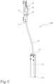
Figure 2 shows a perspective view of the load lightening device ofFigure 1 ; -
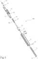
Figure 3 shows an exploded perspective view of the load lightening device; -
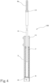
Figure 4 shows a side view, partly in cross section and with some parts cut away in order to better illustrate others, of the load lightening device. - With reference to the accompanying drawings, in particular
Figure 1 , the device for lightening the load according to the invention, labelled 100 in its entirety, is used on doors or windows. - More specifically, the
device 100 is used on doors or windows having a fixed frame 1 and amovable frame 2 which can be opened at least by turning or tilting and connected together through alower hinge 3 and an upper hinge (not illustrated). - As illustrated, the
device 100 for lightening the load comprises abracket 4 associated with the fixed frame 1 (in particular on an upright of the fixed frame 1). - Again as illustrated, the
device 100 comprises acontainment body 5 associated with the movable frame 2 (in particular on an upright of themovable frame 2 and close to the lower hinge 3). - The
device 100 also comprises aunit 6 for transferring the load constrained, at a first end, to thebracket 4 and housed, with the second end, in thecontainment body 5. - Moreover, the
device 100 comprises anelastic element 7 housed inside thecontainment body 5 associated with themovable frame 2 and held between a first end of thecontainment body 5 and the second end of theload transfer unit 6 housed in thecontainment body 5. - As also illustrated in
Figures 2 to 4 , theload lightening device 100 also comprises acontact element 8 associated with the second end of theload transfer unit 6 housed in thecontainment body 5 and designed for retaining an end of theelastic element 7. - The
device 100 also comprises means 9 for adjusting the tensioning of theload transfer unit 6 positioned between thebracket 4 and the first end of theload transfer unit 6 and configured, in use, for modifying the position of thecontact element 8 inside thecontainment body 5, in both directions, in such a way as to compress or decompress theelastic element 7 along thecontainment body 5 in such a way as to modify the load of thedevice 100. In other words, once positioned and mounted, the load lightening device can be adjusted with the preloading of the elastic element directly through a simple operation on the part of the external load transfer unit and positioned on the fixed frame without further operations on the containment body or on the elastic element contained in the containment body. - It should be noted that the
load transfer unit 6 comprises a flexible cable (for example, made of metal). - This solution allows the maximum flexibility of adjustment of the device. As illustrated in
Figures 3 and4 , thecontact element 8 comprises a (circular) plate associated with the second end of theload transfer unit 6. The plate is positioned in contact with the relative end of theelastic element 7 in such a way as to allow a thrust action or a release on/of theelastic element 7 corresponding to a relative greater or lesser compression inside thecontainment body 5 under the action of the adjustment means 9. - In light of this, the adjustment means 9 comprise a threaded
adjustment screw 10 which can be screwed on a threadedportion 6a of the first end of theload transfer unit 6 positioned on thebracket 4. - It should be noted that the
bracket 4 is provided with a reference bushing 11 having a throughseat 12 which can be engaged at least by the threadedportion 6a of the first end of theload transfer unit 6. - In light of this, on a first face of the reference bushing 11 from which at least the threaded
portion 6a of the first end of theload transfer unit 6 protrudes, in use, is positioned theadjustment screw 10 coupled to the threadedportion 6a of theload transfer unit 6 in such a way as to allow a pulling or releasing action on/of thetransfer unit 6 by the contact on the first face of thebushing 11. - The
device 100 also comprises acontact nut 13 constrained on the first end of theload transfer unit 6 and positioned, in use, in contact with a second face of thebushing 11 opposite the first face of thebushing 11 and configured to prevent a rotation of theload transfer unit 6 during the movement of theadjustment screw 10 on the threadedportion 6a of the first end of theload transfer unit 6. - It should be noted that the
contact nut 13 is fitted on the flexible cable defining theload transfer unit 6 and separates the threadedportion 6a of the cable from the remaining cable. - More in detail, the containment body 5 (tubular in shape) has a semi-cylindrical cross-section for housing, in a non-limiting example illustrated of the solution, a helical spring defining the
elastic element 7. - The
elastic element 7 may alternatively consist of a cup-shaped spring or an elastically compliant cylindrical body (not illustrated). - In the embodiment illustrated, The
containment body 5 also comprises acentring bushing 14 fixable on the relative first end in such a way as to retain the end of the elastic element 7 (the spring) and allow the free passage of theload transfer unit 6 from the inside to the outside of thecontainment body 5. - In an alternative embodiment, the
containment body 5 is without the bushing 14 as thecontainment body 5 itself is shaped as if thebushing 14 were integrated into it. - Moreover, associated transversally with the
containment body 5 there is areference pin 15 on the second end of thecontainment body 5 and forming a limit stop or minimum load contact element for the second end of theload transfer unit 6, that is, of the plate. - The
containment body 5 is associated with themovable frame 2 close to thelower hinge 3. This allows a direct lightening of the weight of themovable frame 2 immediately close to thelower hinge 3 which is the one most subjected to the load during opening of the door or window. - Thanks to a device for lightening the load structured in this way the preset aims are achieved.
- The possibility of modifying the preloading of the spring through an adjustment positioned on the fixed part of the door or window allows the components to be mounted quickly and then, without the need for tools or reference elements, adjustment of the compression of the spring in a precise and rapid manner as a function of the weight or of the response of the hinge to the opening force.
- Thanks to this device, it is also possible to adjust the load over time and as a function of wear both of the hinge and of the spring without the need to remove the components of the device.
Claims (8)
- A load lightening device for doors or windows having a fixed frame (1) and a movable frame (2) which can be opened at least by a sash and connected to each other through a lower hinge (3) and an upper hinge; the device (100) comprising at least:- a bracket (4) associated with the fixed frame (1);- a containment body (5) associated with the movable frame (2);- a unit (6) for transferring the load constrained, at a first end, to the bracket (4) and housed, with the second end, in the containment body (5);- an elastic element (7) housed inside the containment body (5) associated with the movable frame (2) and held between a first end of the containment body (5) and the second end of the transfer unit (6) of the load housed in the containment body (5); the suspension being- a contact element (8) associated with the second end of the transfer unit (6) of the load housed in the containment body (5) and configured for retaining an end of the elastic element (7);- means (9) for adjusting the tensioning of the load transfer unit (6) positioned between the bracket (4) and the first end of the transfer unit (6) and configured, in use, for modifying the position of the contact element (8) inside the containment body (5), in both directions, in such a way as to compress or decompress the elastic element (7) along the containment body (5) in such a way as to modify the load of the device (100);the adjustment means (9) comprise a threaded adjustment screw (10) which can be screwed on a threaded portion (6a) of the first end of the transfer unit (6) positioned on the bracket (4);characterised in thatthe bracket (4) is provided with a reference bushing (11) having a through seat (12) which can be engaged at least by the threaded portion (6a) of the first end of the transfer unit (6); on a first face of the reference bushing (11) from which protrudes at least the threaded portion (6a) of the first end of the transfer unit (6) being positioned, in use, the adjustment screw (10) in such a way as to allow a pulling or releasing action on/of the transfer unit (6) by the contact on the first face of the bushing (11).
- The device according to claim 1, wherein the contact element (8) comprises a plate associated with the second end of the transfer unit (6) and positioned in contact with the relative end of the elastic element (7) in such a way as to allow a thrust or a release on the elastic element (7) corresponding to a relative greater or lesser compression inside the containment body (5).
- The device according to claim 1 or 2, comprising a contact nut (13) constrained on the first end of the transfer unit (6) and positioned, in use, in contact with a second face of the bushing (11) opposite the first face of the bushing (11) and configured to prevent a rotation of the transfer unit (6) during the movement of the adjustment screw (10) on the threaded portion (6a) of the first end of the transfer unit (6).
- The device according to any one of the preceding claims, wherein the containment body (5) has a semi-cylindrical cross-section to house a helical spring or a cup-shaped spring or a body with an elastically compliant cylindrical shape defining the elastic element (7).
- The device according to any one of the preceding claims, wherein the containment body (5) comprises a centring bushing (14) fixable on the relative first end in such a way as to retain the end of the elastic element (7) and allow the free passage of the transfer unit (6) from the inside to the outside of the containment body (5).
- The device according to claim 4 or 5, wherein a reference pin (15) is associated, transversely, on the containment body (5) on the second end of the containment body (5) and forming a limit stop or minimum load contact element for the second end of the transfer unit (6).
- The device according to any one of the preceding claims, wherein the containment body (5) is associated with the movable frame (2) close to the lower hinge (3).
- The device according to any one of the preceding claims, wherein the transfer unit (6) comprises a flexible cable.
Applications Claiming Priority (1)
| Application Number | Priority Date | Filing Date | Title |
|---|---|---|---|
| IT102023000024774A IT202300024774A1 (en) | 2023-11-22 | 2023-11-22 | LOAD LIGHTENING DEVICE FOR DOORS OR WINDOWS. |
Publications (2)
| Publication Number | Publication Date |
|---|---|
| EP4560100A1 true EP4560100A1 (en) | 2025-05-28 |
| EP4560100B1 EP4560100B1 (en) | 2025-12-03 |
Family
ID=89663100
Family Applications (1)
| Application Number | Title | Priority Date | Filing Date |
|---|---|---|---|
| EP24214144.8A Active EP4560100B1 (en) | 2023-11-22 | 2024-11-20 | Load lightening device for doors or windows |
Country Status (5)
| Country | Link |
|---|---|
| EP (1) | EP4560100B1 (en) |
| ES (1) | ES3061915T3 (en) |
| IT (1) | IT202300024774A1 (en) |
| PL (1) | PL4560100T3 (en) |
| PT (1) | PT4560100T (en) |
Citations (4)
| Publication number | Priority date | Publication date | Assignee | Title |
|---|---|---|---|---|
| DE102010043739A1 (en) * | 2010-11-11 | 2012-05-16 | Roto Frank Ag | Relief assembly of window or door, has one control element which is arranged to vary the stress state of spring assembly relative to another control element |
| EP1837472B1 (en) * | 2006-03-25 | 2013-08-14 | Roto Frank Ag | Window, door or similar with a load alleviation device |
| CN217028506U (en) * | 2022-03-09 | 2022-07-22 | 深圳好博窗控技术股份有限公司 | Bearing accessory and window |
| CN116480240A (en) * | 2023-04-18 | 2023-07-25 | 广东合和建筑五金制品有限公司 | Lifting part for window sashes and its usage method, window structure |
-
2023
- 2023-11-22 IT IT102023000024774A patent/IT202300024774A1/en unknown
-
2024
- 2024-11-20 EP EP24214144.8A patent/EP4560100B1/en active Active
- 2024-11-20 PL PL24214144.8T patent/PL4560100T3/en unknown
- 2024-11-20 ES ES24214144T patent/ES3061915T3/en active Active
- 2024-11-20 PT PT242141448T patent/PT4560100T/en unknown
Patent Citations (4)
| Publication number | Priority date | Publication date | Assignee | Title |
|---|---|---|---|---|
| EP1837472B1 (en) * | 2006-03-25 | 2013-08-14 | Roto Frank Ag | Window, door or similar with a load alleviation device |
| DE102010043739A1 (en) * | 2010-11-11 | 2012-05-16 | Roto Frank Ag | Relief assembly of window or door, has one control element which is arranged to vary the stress state of spring assembly relative to another control element |
| CN217028506U (en) * | 2022-03-09 | 2022-07-22 | 深圳好博窗控技术股份有限公司 | Bearing accessory and window |
| CN116480240A (en) * | 2023-04-18 | 2023-07-25 | 广东合和建筑五金制品有限公司 | Lifting part for window sashes and its usage method, window structure |
Also Published As
| Publication number | Publication date |
|---|---|
| PL4560100T3 (en) | 2026-04-07 |
| EP4560100B1 (en) | 2025-12-03 |
| IT202300024774A1 (en) | 2025-05-22 |
| ES3061915T3 (en) | 2026-04-08 |
| PT4560100T (en) | 2026-02-12 |
Similar Documents
| Publication | Publication Date | Title |
|---|---|---|
| EP2617336B1 (en) | Shower separator | |
| EP1997994B1 (en) | Hinge | |
| KR101758840B1 (en) | Door closer | |
| EP0330129B1 (en) | Door closers | |
| EP3555399B1 (en) | Hinge for the rotatable movement of a door, a shutter or the like | |
| CN112211519A (en) | Closure panel balancing mechanism with threaded connection | |
| KR101958219B1 (en) | Door hinge | |
| CN101718163B (en) | Load alleviation assembly for a window, door or similar | |
| KR200190938Y1 (en) | Door-hinge device having auto-locking function | |
| EP4560100B1 (en) | Load lightening device for doors or windows | |
| CN105658892B (en) | Window OR gate including accessory | |
| EP3251571B1 (en) | Hinge for pivoting a door | |
| CN115030617B (en) | Anti-tilting structure and hinge with same | |
| EP0649963B1 (en) | Selectable friction assisted door holder assembly | |
| AU2016238980B2 (en) | Adjustable Operator Worm Gear Drive with Robust Bearing Surfaces | |
| CN101223328A (en) | Hinge | |
| DE29503024U1 (en) | Wing bearing | |
| KR20170034198A (en) | Effort adjustable door checker and assembly the same | |
| KR200243185Y1 (en) | Inner type door open & close damper | |
| KR100328395B1 (en) | Automatic Door Apparatus | |
| EP1533439B1 (en) | Servo-lifting device | |
| EP4711571A1 (en) | Auxiliary support device for doors or windows with at least one hinged leaf, swing leaf door or window and method for increasing the bearing capacity of a door or window | |
| KR102581698B1 (en) | Roller Unit for Folding Door | |
| KR200271646Y1 (en) | Door hinge having hydraulic and spring type door closers | |
| JP7855204B1 (en) | Doors and windows |
Legal Events
| Date | Code | Title | Description |
|---|---|---|---|
| PUAI | Public reference made under article 153(3) epc to a published international application that has entered the european phase |
Free format text: ORIGINAL CODE: 0009012 |
|
| STAA | Information on the status of an ep patent application or granted ep patent |
Free format text: STATUS: THE APPLICATION HAS BEEN PUBLISHED |
|
| AK | Designated contracting states |
Kind code of ref document: A1 Designated state(s): AL AT BE BG CH CY CZ DE DK EE ES FI FR GB GR HR HU IE IS IT LI LT LU LV MC ME MK MT NL NO PL PT RO RS SE SI SK SM TR |
|
| STAA | Information on the status of an ep patent application or granted ep patent |
Free format text: STATUS: REQUEST FOR EXAMINATION WAS MADE |
|
| GRAP | Despatch of communication of intention to grant a patent |
Free format text: ORIGINAL CODE: EPIDOSNIGR1 |
|
| STAA | Information on the status of an ep patent application or granted ep patent |
Free format text: STATUS: GRANT OF PATENT IS INTENDED |
|
| 17P | Request for examination filed |
Effective date: 20250626 |
|
| RIC1 | Information provided on ipc code assigned before grant |
Ipc: E05D 15/526 20060101AFI20250627BHEP Ipc: E05F 7/06 20060101ALI20250627BHEP |
|
| INTG | Intention to grant announced |
Effective date: 20250729 |
|
| GRAS | Grant fee paid |
Free format text: ORIGINAL CODE: EPIDOSNIGR3 |
|
| GRAA | (expected) grant |
Free format text: ORIGINAL CODE: 0009210 |
|
| STAA | Information on the status of an ep patent application or granted ep patent |
Free format text: STATUS: THE PATENT HAS BEEN GRANTED |
|
| AK | Designated contracting states |
Kind code of ref document: B1 Designated state(s): AL AT BE BG CH CY CZ DE DK EE ES FI FR GB GR HR HU IE IS IT LI LT LU LV MC ME MK MT NL NO PL PT RO RS SE SI SK SM TR |
|
| P01 | Opt-out of the competence of the unified patent court (upc) registered |
Free format text: CASE NUMBER: UPC_APP_0010897_4560100/2025 Effective date: 20251023 |
|
| REG | Reference to a national code |
Ref country code: CH Ref legal event code: F10 Free format text: ST27 STATUS EVENT CODE: U-0-0-F10-F00 (AS PROVIDED BY THE NATIONAL OFFICE) Effective date: 20251203 Ref country code: GB Ref legal event code: FG4D |
|
| REG | Reference to a national code |
Ref country code: DE Ref legal event code: R096 Ref document number: 602024001527 Country of ref document: DE |
|
| REG | Reference to a national code |
Ref country code: IE Ref legal event code: FG4D |
|
| REG | Reference to a national code |
Ref country code: PT Ref legal event code: SC4A Ref document number: 4560100 Country of ref document: PT Date of ref document: 20260212 Kind code of ref document: T Free format text: AVAILABILITY OF NATIONAL TRANSLATION Effective date: 20260206 |
|
| REG | Reference to a national code |
Ref country code: ES Ref legal event code: FG2A Ref document number: 3061915 Country of ref document: ES Kind code of ref document: T3 Effective date: 20260408 Ref country code: NL Ref legal event code: MP Effective date: 20251203 |
|
| REG | Reference to a national code |
Ref country code: LT Ref legal event code: MG9D |
|
| PG25 | Lapsed in a contracting state [announced via postgrant information from national office to epo] |
Ref country code: NO Free format text: LAPSE BECAUSE OF FAILURE TO SUBMIT A TRANSLATION OF THE DESCRIPTION OR TO PAY THE FEE WITHIN THE PRESCRIBED TIME-LIMIT Effective date: 20260303 |
|
| PG25 | Lapsed in a contracting state [announced via postgrant information from national office to epo] |
Ref country code: HR Free format text: LAPSE BECAUSE OF FAILURE TO SUBMIT A TRANSLATION OF THE DESCRIPTION OR TO PAY THE FEE WITHIN THE PRESCRIBED TIME-LIMIT Effective date: 20251203 Ref country code: FI Free format text: LAPSE BECAUSE OF FAILURE TO SUBMIT A TRANSLATION OF THE DESCRIPTION OR TO PAY THE FEE WITHIN THE PRESCRIBED TIME-LIMIT Effective date: 20251203 |
|
| PG25 | Lapsed in a contracting state [announced via postgrant information from national office to epo] |
Ref country code: RS Free format text: LAPSE BECAUSE OF FAILURE TO SUBMIT A TRANSLATION OF THE DESCRIPTION OR TO PAY THE FEE WITHIN THE PRESCRIBED TIME-LIMIT Effective date: 20260303 |
|
| PG25 | Lapsed in a contracting state [announced via postgrant information from national office to epo] |
Ref country code: LV Free format text: LAPSE BECAUSE OF FAILURE TO SUBMIT A TRANSLATION OF THE DESCRIPTION OR TO PAY THE FEE WITHIN THE PRESCRIBED TIME-LIMIT Effective date: 20251203 |
|
| PG25 | Lapsed in a contracting state [announced via postgrant information from national office to epo] |
Ref country code: BG Free format text: LAPSE BECAUSE OF FAILURE TO SUBMIT A TRANSLATION OF THE DESCRIPTION OR TO PAY THE FEE WITHIN THE PRESCRIBED TIME-LIMIT Effective date: 20251203 |
|
| REG | Reference to a national code |
Ref country code: AT Ref legal event code: MK05 Ref document number: 1863776 Country of ref document: AT Kind code of ref document: T Effective date: 20251203 |
|
| PG25 | Lapsed in a contracting state [announced via postgrant information from national office to epo] |
Ref country code: NL Free format text: LAPSE BECAUSE OF FAILURE TO SUBMIT A TRANSLATION OF THE DESCRIPTION OR TO PAY THE FEE WITHIN THE PRESCRIBED TIME-LIMIT Effective date: 20251203 |
|
| PG25 | Lapsed in a contracting state [announced via postgrant information from national office to epo] |
Ref country code: LT Free format text: LAPSE BECAUSE OF FAILURE TO SUBMIT A TRANSLATION OF THE DESCRIPTION OR TO PAY THE FEE WITHIN THE PRESCRIBED TIME-LIMIT Effective date: 20251203 |
|
| PG25 | Lapsed in a contracting state [announced via postgrant information from national office to epo] |
Ref country code: SM Free format text: LAPSE BECAUSE OF FAILURE TO SUBMIT A TRANSLATION OF THE DESCRIPTION OR TO PAY THE FEE WITHIN THE PRESCRIBED TIME-LIMIT Effective date: 20251203 |
|
| PG25 | Lapsed in a contracting state [announced via postgrant information from national office to epo] |
Ref country code: AT Free format text: LAPSE BECAUSE OF FAILURE TO SUBMIT A TRANSLATION OF THE DESCRIPTION OR TO PAY THE FEE WITHIN THE PRESCRIBED TIME-LIMIT Effective date: 20251203 |
|
| PG25 | Lapsed in a contracting state [announced via postgrant information from national office to epo] |
Ref country code: EE Free format text: LAPSE BECAUSE OF FAILURE TO SUBMIT A TRANSLATION OF THE DESCRIPTION OR TO PAY THE FEE WITHIN THE PRESCRIBED TIME-LIMIT Effective date: 20251203 |
|
| PG25 | Lapsed in a contracting state [announced via postgrant information from national office to epo] |
Ref country code: IS Free format text: LAPSE BECAUSE OF FAILURE TO SUBMIT A TRANSLATION OF THE DESCRIPTION OR TO PAY THE FEE WITHIN THE PRESCRIBED TIME-LIMIT Effective date: 20260403 |
|
| PG25 | Lapsed in a contracting state [announced via postgrant information from national office to epo] |
Ref country code: CZ Free format text: LAPSE BECAUSE OF FAILURE TO SUBMIT A TRANSLATION OF THE DESCRIPTION OR TO PAY THE FEE WITHIN THE PRESCRIBED TIME-LIMIT Effective date: 20251203 |
|
| PG25 | Lapsed in a contracting state [announced via postgrant information from national office to epo] |
Ref country code: SK Free format text: LAPSE BECAUSE OF FAILURE TO SUBMIT A TRANSLATION OF THE DESCRIPTION OR TO PAY THE FEE WITHIN THE PRESCRIBED TIME-LIMIT Effective date: 20251203 |
|
| PG25 | Lapsed in a contracting state [announced via postgrant information from national office to epo] |
Ref country code: SE Free format text: LAPSE BECAUSE OF FAILURE TO SUBMIT A TRANSLATION OF THE DESCRIPTION OR TO PAY THE FEE WITHIN THE PRESCRIBED TIME-LIMIT Effective date: 20251203 |