EP4560094A1 - Panic bar - Google Patents
Panic bar Download PDFInfo
- Publication number
- EP4560094A1 EP4560094A1 EP24212036.8A EP24212036A EP4560094A1 EP 4560094 A1 EP4560094 A1 EP 4560094A1 EP 24212036 A EP24212036 A EP 24212036A EP 4560094 A1 EP4560094 A1 EP 4560094A1
- Authority
- EP
- European Patent Office
- Prior art keywords
- control rod
- latch
- bar
- magnetic field
- movement
- Prior art date
- Legal status (The legal status is an assumption and is not a legal conclusion. Google has not performed a legal analysis and makes no representation as to the accuracy of the status listed.)
- Granted
Links
Images


Classifications
-
- E—FIXED CONSTRUCTIONS
- E05—LOCKS; KEYS; WINDOW OR DOOR FITTINGS; SAFES
- E05B—LOCKS; ACCESSORIES THEREFOR; HANDCUFFS
- E05B65/00—Locks or fastenings for special use
- E05B65/10—Locks or fastenings for special use for panic or emergency doors
- E05B65/1046—Panic bars
- E05B65/1053—Panic bars sliding towards and away form the door
-
- E—FIXED CONSTRUCTIONS
- E05—LOCKS; KEYS; WINDOW OR DOOR FITTINGS; SAFES
- E05B—LOCKS; ACCESSORIES THEREFOR; HANDCUFFS
- E05B47/00—Operating or controlling locks or other fastening devices by electric or magnetic means
- E05B47/0001—Operating or controlling locks or other fastening devices by electric or magnetic means with electric actuators; Constructional features thereof
- E05B47/0012—Operating or controlling locks or other fastening devices by electric or magnetic means with electric actuators; Constructional features thereof with rotary electromotors
-
- E—FIXED CONSTRUCTIONS
- E05—LOCKS; KEYS; WINDOW OR DOOR FITTINGS; SAFES
- E05B—LOCKS; ACCESSORIES THEREFOR; HANDCUFFS
- E05B47/00—Operating or controlling locks or other fastening devices by electric or magnetic means
- E05B47/02—Movement of the bolt by electromagnetic means; Adaptation of locks, latches, or parts thereof, for movement of the bolt by electromagnetic means
- E05B47/023—Movement of the bolt by electromagnetic means; Adaptation of locks, latches, or parts thereof, for movement of the bolt by electromagnetic means the bolt moving pivotally or rotatively
-
- E—FIXED CONSTRUCTIONS
- E05—LOCKS; KEYS; WINDOW OR DOOR FITTINGS; SAFES
- E05B—LOCKS; ACCESSORIES THEREFOR; HANDCUFFS
- E05B65/00—Locks or fastenings for special use
- E05B65/10—Locks or fastenings for special use for panic or emergency doors
- E05B65/108—Electronically controlled emergency exits
-
- E—FIXED CONSTRUCTIONS
- E05—LOCKS; KEYS; WINDOW OR DOOR FITTINGS; SAFES
- E05B—LOCKS; ACCESSORIES THEREFOR; HANDCUFFS
- E05B47/00—Operating or controlling locks or other fastening devices by electric or magnetic means
- E05B47/0001—Operating or controlling locks or other fastening devices by electric or magnetic means with electric actuators; Constructional features thereof
- E05B2047/0014—Constructional features of actuators or power transmissions therefor
- E05B2047/0018—Details of actuator transmissions
- E05B2047/002—Geared transmissions
-
- E—FIXED CONSTRUCTIONS
- E05—LOCKS; KEYS; WINDOW OR DOOR FITTINGS; SAFES
- E05B—LOCKS; ACCESSORIES THEREFOR; HANDCUFFS
- E05B47/00—Operating or controlling locks or other fastening devices by electric or magnetic means
- E05B2047/0048—Circuits, feeding, monitoring
- E05B2047/0067—Monitoring
- E05B2047/0069—Monitoring bolt position
-
- E—FIXED CONSTRUCTIONS
- E05—LOCKS; KEYS; WINDOW OR DOOR FITTINGS; SAFES
- E05B—LOCKS; ACCESSORIES THEREFOR; HANDCUFFS
- E05B47/00—Operating or controlling locks or other fastening devices by electric or magnetic means
- E05B2047/0091—Retrofittable electric locks, e.g. an electric module can be attached to an existing manual lock
-
- E—FIXED CONSTRUCTIONS
- E05—LOCKS; KEYS; WINDOW OR DOOR FITTINGS; SAFES
- E05B—LOCKS; ACCESSORIES THEREFOR; HANDCUFFS
- E05B47/00—Operating or controlling locks or other fastening devices by electric or magnetic means
- E05B2047/0094—Mechanical aspects of remotely controlled locks
Definitions
- the present invention pertains to a panic bar that includes a manually operated push bar placed along a longitudinal support base and movable in a direction transverse to its longitudinal axis to operate a latch control rod.
- Detecting the starting and ending positions of the latch control rod can also be used to track the number of times the panic bar is activated.
- panic bars One of the common issues in these versions of panic bars is that the sensors positioned on the support base require long and complex electrical wiring for power supply and signal transmission.
- the wiring may settle and interfere with moving parts, jeopardizing the integrity and/or functionality of the sensor system.
- the sensors are exposed to environmental contamination, and dirt accumulation can further degrade their performance.
- Patent US2012/261928 A1 discloses a panic bar according to the preamble of claim 1, while EP 3 271 531 B1 shows a panic bar with a motorized module.
- the technical objective of the present invention is, therefore, to develop an electromechanical panic bar that overcomes the technical drawbacks of known designs.
- an aim of the invention is to create an electromechanical panic bar that maintains high performance over time.
- Another aim of the invention is to provide an electromechanical panic bar that is easy to assemble. Additionally, the invention aims to supply an electromechanical panic bar with high operational flexibility, allowing tracking of activations caused by both the manual push bar and the geared motor.
- a panic bar that includes a longitudinal support base, a manually operated push bar arranged along this support base, a latch, a latch control rod positioned in a longitudinal cavity delimited between the support base and the manual push bar, and having a proximal end near to the latch and a distal end away from the latch, in that cavity an automatic reset elastic element for the manual push bar, a first rotatable element for actuating the control rod, a second actuating element for the control rod that operates independently of the first rotatable element, magnetic position sensors means for the control rod, and a motorized module for actuating the second element are present , wherein the motorized module comprises a gearmotor and a shell for housing both the gearmotor and the magnetic sensors means, which is fixed to the support base.
- the magnetic sensor means include a magnetic field-generating element supported by an extension on the distal end of the control rod, extending into the housing, and at least a first magnetic field-sensitive element fixed within the housing.
- the second movement element engages the control rod in a disengageable manner.
- the second movement element is translatable.
- the magnetic sensor means include a second magnetic field-sensitive element fixed within the housing, where the magnetic field-generating element can align with the first magnetic field-sensitive element to indicate the position of the control rod corresponding to an open state of the latch, and with the second magnetic field-sensitive element to indicate the position of the control rod corresponding to a closed state of the latch.
- the first rotatable movement element is configured to transform movement from the manual push bar into movement of the control rod, is rotatable against and by action of the elastic reset element and includes a cam that captures movement from the manual push bar and a cam that transfers movement to the latch control rod.
- this movement-transferring cam is configured to impart to the latch control rod a motion that includes both a translational and a rotational component.
- the extension is formed by a series of elements, including a proximal terminal element close to the control rod, a distal terminal element away from the control rod, and an intermediate articulated connection element between the proximal terminal element close to the control rod and the distal terminal element.
- the proximal terminal element close to the control rod is rigidly fixed to the control rod.
- the magnetic field-generating element is supported by the distal terminal element.
- the distal terminal element is slidable along a linear guide supported by the translatable element.
- the distal terminal element and the translatable element are movable parallel to one another.
- the panic bar 1 includes a manual push bar 2 arranged along a longitudinal support base 3. More precisely, the support base 3 is made of a "U" profile that houses the push bar 2, which is also made of a "U” profile, with its concave side facing that of the base 3.
- the top wall of the push bar 2 faces the bottom wall 4 of the support base 3, while the side walls of the push bar 2 are positioned further inside than the side walls of the base 3.
- the bottom wall 4 of the support base 3 is flat for attachment to the wall of a door frame.
- the push bar 2 is supported by the support base 3 in a way that allows reversible sliding movement perpendicular to the flat bottom wall 4 of the support base 3.
- the panic bar also includes a latch 5 and a control rod 6 for the latch 5, positioned in the longitudinal cavity 7, which is enclosed between the support base 3 and the push bar 2.
- the control rod 6 has a proximal end 6a near the latch 5 and a distal end 6b away from the latch 5.
- the motorized module 11 includes a motorized reducer 12, 13, and a housing 14 for the motorized reducer 12, 13, fixed to the support base 3.
- the housing 14 also contains specialized magnetic position sensors 15, 19, 20, configured and arranged to detect the position of the control rod 6.
- the control rod 6 can be operated independently via the first movement element 9 and the second movement element 10.
- the second movement element 10 can engage the control rod 6 in a disengageable manner, and it is translatable.
- the first movement element 9 of the control rod 6 is configured to transform the movement of the manual push bar 2 into movement of the control rod 6 and is rotatable against and by the action of the reset elastic element 8.
- the sensor means 15, 19, 20 include a magnetic field-generating element 15 supported by an extension 16, 17, 18 on the distal end 6b of the control rod 6.
- the magnetic field-generating element 15 is specifically a permanent magnet.
- the extension 16, 17, 18 on the distal end 6b of the control rod 6 extends inside the housing 14.
- the magnetic sensors 15, 19, 20 include at least one first magnetic field-sensitive element 19 fixed within the housing 14, and preferably a second magnetic field-sensitive element 20 also fixed within the housing 14.
- the first magnetic field-sensitive element 19 and the second magnetic field-sensitive element 20 are arranged offset along the translation path of the magnetic field-generating element 15 and are mounted on an electronic board 26, also housed in a fixed position inside the housing 14.
- the magnetic field-generating element 15 can align with the first magnetic field-sensitive element 19 to signal the position of the control rod 6 corresponding to an open state of the latch 5, in which the latch is retracted within the cavity 7, and with the second magnetic field-sensitive element 20 to signal the position of the control rod 6 corresponding to a closed state of the latch 5, in which the latch protrudes outside the cavity 7.
- the first movement element 9 of the control rod 6 is positioned within the longitudinal cavity 7, enclosed between the support base 3 and the push bar 2. Specifically, the first movement element 9 of the control rod 6 is pivoted to the support base 3 with a rotation axis 21 perpendicular to the movement axis of the push bar 2 and the longitudinal axis of the support base 3. More precisely, the movement axis of the push bar 2 is horizontal, while the rotation axis 21 of the first movement element 9 is vertical.
- the first movement element 9 of the control rod 6 includes a cam 22 to receive movement from the push bar 2 and a cam 23 to transmit movement to the control rod 6.
- the movement-receiving cam 22 from the push bar 2 consists of two opposing pins that slide along corresponding, mirror-image longitudinal slots 27 on the inner side walls of the push bar 2.
- the movement-transmitting cam 23 is specifically configured to transmit to the control rod 6 a motion that has a primary component of longitudinal translational movement and a secondary component of rotational movement.
- the movement-transmitting cam 23 is formed by two open, curvilinear, mirror-image slots located on the two sides of the first movement element 9 of the control rod 6, in which corresponding pins 24 slide, extending symmetrically from both sides of the distal end 6b of the control rod 6.
- the reset elastic element 8 is specifically a torsional spring wound around the rotation axis 21 of the first movement element 9 of the control rod 6, with one fixed end and one end that can be rotated by the first movement element 9 of the control rod 6.
- the latch 5 is operatively connected to the control rod 6 and is supported by the support base 3 with a rotation axis parallel to the rotation axis 21 of the first movement element 9 of the control rod 6.
- the operative connection between the control rod 6 and the latch 5 can be achieved through an actuating pin of the latch 5 fixed to the control rod 6, which slides within a slot on the latch 5, or vice versa.
- the torsional spring 8 unloads, rotating the first movement element 9 in the opposite direction, pulling the control rod 6 in a direction that causes the latch 5 to extend outward from the cavity 7, thus closing the door.
- the extension 16, 17, 18 consists of a series of elements, including a proximal terminal element 16 near the control rod 6 and a distal terminal element 18 away from the control rod 6.
- This series of elements also includes an intermediate articulated connection element 17 between the proximal terminal element 16 near the control rod 6 and the distal terminal element 18.
- the proximal terminal element 16 is rigidly attached to the control rod 6.
- the magnetic field-generating element 15 is supported by the distal terminal element 18 of the extension 16, 17, 18 on the distal end 6b of the control rod 6.
- the distal terminal element 18 of the distal end 6b of the control rod 6 slides along a linear guide 25 supported by the second translatable element 10.
- the distal terminal element 18 and the second movement element 10 move parallel to each other, particularly in the longitudinal direction of the support base 3.
- the second movement element 10 of the control rod 6 is configured and arranged to engage the distal end 6b of the control rod 6, specifically a stop feature designed on the distal end 6b of the control rod 6, thereby pushing the control rod 6.
- the second movement element 10 includes a rack 28, which meshes with a terminal gear 30 of a gear assembly with various diameters 30 that forms the reducer 13.
- the first gear 30 of the assembly meshes with the thread of a threaded rod 31, which can rotate on its axis, driven by the motor 12.
- the gears 30 have an axis of rotation parallel to the rotation axis 21 of the first movement element 9 of the control rod 6.
- the threaded rod 31 has an axis inclined relative to the longitudinal direction of the support base 3.
- the operation of the panic bar 1 is briefly as follows:
- the first mode of operation is manual activation of the panic bar 1 via the push bar 2.
- the control rod 6 is in a position where the latch 5 is extended, keeping the door closed.
- the push bar 2 is pressed, it rotates the first movement element 9, which in turn pushes the control rod 6 in a direction that corresponds to the retraction of the latch 5, opening the door.
- the control rod 6 then also rotates the first movement element 9, loading the torsional spring 8.
- the door remains in the open state as long as manual pressure is applied to the push bar 2.
- the reset spring 8 automatically returns the control rod 6 to its initial position.
- the magnetic field-generating element 15 aligns with the second magnetic field-sensitive element 20, which detects this alignment and signals it to the electronic board 26, identifying this alignment condition as the closed state of the latch 5.
- the magnetic field-generating element 15 aligns with the first magnetic field-sensitive element 19, which detects this alignment and signals it to the electronic board 26, identifying this alignment condition as the open state of the latch 5.
- the second mode of operation is when the panic bar 1 is activated via the motorized module 12, 13, which can be controlled remotely.
- the control rod 6 is in a position where the latch 5 is extended to close the door.
- the motorized reducer 12, 13 moves the second movement element 10, which in turn moves the control rod 6 in a direction corresponding to the retraction of the latch 5, opening the door.
- the control rod 6, in turn, rotates the first movement element 9, loading the torsional spring 8.
- the stroke of the control rod 6 occurs between an initial position, where the magnetic field-generating element 15 aligns with the second magnetic field-sensitive element 20, and a final position, where the magnetic field-generating element 15 aligns with the first magnetic field-sensitive element 19.
- the first magnetic field-sensitive element detects this alignment of the magnetic field-generating element 15 and signals it to the electronic board 26, which then stops the motorized reducer 12, 13.
- the motorized reducer 12, 13 When the motor 12 is activated in the opposite direction following a remote command to close the door, the motorized reducer 12, 13 returns to the initial configuration where the magnetic field-generating element 15 aligns with the second magnetic field-sensitive element 20. The second magnetic field-sensitive element 20 detects this alignment and signals it to the electronic board 26, which stops the motorized reducer 12, 13.
- the second movement element 10 returns to its initial position thanks to the force exerted on it by the distal end 6b of the control rod 6, which is moved by the reset spring 8.
- the first and second magnetic field-sensitive elements (19 and 20) detect two positions of the magnetic field-generating element 15, which correspond to stopping the motor 12 of the motorized reducer 12, 13.
- the electronic board 26 can count and record the number of door openings triggered by both the push bar 2 and the motorized module 11.
- the motorized module 11 is compatible for retrofit installation, allowing upgrades to products already on the market without requiring replacement of other components of the panic lock 1.
- the protected placement of the position sensors within the housing 14 of the motorized module 11 eliminates many issues encountered in known technologies, as it does not require complex electrical wiring exposed to environmental contamination.
- the panic bar as conceived, is open to numerous modifications and variations, all falling within the inventive concept; furthermore, all details can be replaced with technically equivalent elements. Practically, the materials used, as well as the dimensions, can be adapted according to requirements and the state of the art.
Landscapes
- Business, Economics & Management (AREA)
- Emergency Management (AREA)
- Physics & Mathematics (AREA)
- Electromagnetism (AREA)
- Mechanical Control Devices (AREA)
- Lock And Its Accessories (AREA)
Abstract
Description
- The present invention pertains to a panic bar that includes a manually operated push bar placed along a longitudinal support base and movable in a direction transverse to its longitudinal axis to operate a latch control rod.
- Electromechanical versions of panic bars are available on the market, in which the latch can be operated independently by the push bar or a geared motor. In these versions, sensor systems sometimes detect the starting and ending positions of the latch control rod to stop the geared motor and reverse its rotation.
- Detecting the starting and ending positions of the latch control rod can also be used to track the number of times the panic bar is activated.
- One of the common issues in these versions of panic bars is that the sensors positioned on the support base require long and complex electrical wiring for power supply and signal transmission.
- Over time, the wiring may settle and interfere with moving parts, jeopardizing the integrity and/or functionality of the sensor system.
- Additionally, the sensors are exposed to environmental contamination, and dirt accumulation can further degrade their performance.
- Patent
US2012/261928 A1 discloses a panic bar according to the preamble ofclaim 1, whileEP 3 271 531 B1 - The technical objective of the present invention is, therefore, to develop an electromechanical panic bar that overcomes the technical drawbacks of known designs.
- Within this technical objective, an aim of the invention is to create an electromechanical panic bar that maintains high performance over time.
- Another aim of the invention is to provide an electromechanical panic bar that is easy to assemble. Additionally, the invention aims to supply an electromechanical panic bar with high operational flexibility, allowing tracking of activations caused by both the manual push bar and the geared motor.
- The technical objective, as well as these and other aims, are achieved in the present invention by a panic bar that includes a longitudinal support base, a manually operated push bar arranged along this support base, a latch, a latch control rod positioned in a longitudinal cavity delimited between the support base and the manual push bar, and having a proximal end near to the latch and a distal end away from the latch, in that cavity an automatic reset elastic element for the manual push bar, a first rotatable element for actuating the control rod, a second actuating element for the control rod that operates independently of the first rotatable element, magnetic position sensors means for the control rod, and a motorized module for actuating the second element are present , wherein the motorized module comprises a gearmotor and a shell for housing both the gearmotor and the magnetic sensors means, which is fixed to the support base.
- In a preferred embodiment of the invention, the magnetic sensor means include a magnetic field-generating element supported by an extension on the distal end of the control rod, extending into the housing, and at least a first magnetic field-sensitive element fixed within the housing.
- In a preferred embodiment of the invention, the second movement element engages the control rod in a disengageable manner.
- In a preferred embodiment of the invention, the second movement element is translatable.
- In a preferred embodiment of the invention, the magnetic sensor means include a second magnetic field-sensitive element fixed within the housing, where the magnetic field-generating element can align with the first magnetic field-sensitive element to indicate the position of the control rod corresponding to an open state of the latch, and with the second magnetic field-sensitive element to indicate the position of the control rod corresponding to a closed state of the latch.
- In a preferred embodiment of the invention, the first rotatable movement element is configured to transform movement from the manual push bar into movement of the control rod, is rotatable against and by action of the elastic reset element and includes a cam that captures movement from the manual push bar and a cam that transfers movement to the latch control rod.
- In a preferred embodiment of the invention, this movement-transferring cam is configured to impart to the latch control rod a motion that includes both a translational and a rotational component.
- In a preferred embodiment of the invention, the extension is formed by a series of elements, including a proximal terminal element close to the control rod, a distal terminal element away from the control rod, and an intermediate articulated connection element between the proximal terminal element close to the control rod and the distal terminal element.
- In a preferred embodiment of the invention, the proximal terminal element close to the control rod is rigidly fixed to the control rod.
- In a preferred embodiment of the invention, the magnetic field-generating element is supported by the distal terminal element.
- In a preferred embodiment of the invention, the distal terminal element is slidable along a linear guide supported by the translatable element.
- In a preferred embodiment of the invention, the distal terminal element and the translatable element are movable parallel to one another.
- Additional features and advantages of the invention will become more evident from the description of a preferred but non-exclusive embodiment of the panic bar, provided illustratively and not restrictively in the accompanying drawings, in which:
-
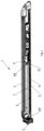
Figure 1 shows an axonometric view of the panic bar without the motorized module and the manual push bar for viewing convenience; -
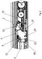
Figure 2 shows an axonometric view of a detail of the panic bar corresponding to the extension of the control bar; -
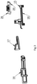
Figure 3 shows an exploded view of the extension of the control bar and the electronic board where the second and third magnetic elements are mounted; -
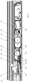
Figure 4A shows a top view of the panic bar with the manual push bar (sectioned along a horizontal longitudinal plane) at rest; -
Figure 4B shows a top view of the panic bar with the control rod actuated by the manual push bar (sectioned along a horizontal longitudinal plane), manually pressed; -
Figure 4C shows a top view of the panic bar with the control rod actuated by the motorized module. - Referring to the cited figures, a panic bar is shown, designated overall by
reference number 1. Thepanic bar 1 includes amanual push bar 2 arranged along alongitudinal support base 3. More precisely, thesupport base 3 is made of a "U" profile that houses thepush bar 2, which is also made of a "U" profile, with its concave side facing that of thebase 3. - The top wall of the
push bar 2 faces thebottom wall 4 of thesupport base 3, while the side walls of thepush bar 2 are positioned further inside than the side walls of thebase 3. Thebottom wall 4 of thesupport base 3 is flat for attachment to the wall of a door frame. Thepush bar 2 is supported by thesupport base 3 in a way that allows reversible sliding movement perpendicular to theflat bottom wall 4 of thesupport base 3. - The panic bar also includes a
latch 5 and acontrol rod 6 for thelatch 5, positioned in thelongitudinal cavity 7, which is enclosed between thesupport base 3 and thepush bar 2. Thecontrol rod 6 has a proximal end 6a near thelatch 5 and a distal end 6b away from thelatch 5. - In the
longitudinal cavity 7, there is also anelastic element 8 for the automatic reset of thepush bar 2, a firstrotatable movement element 9 for operating thecontrol rod 6, asecond movement element 10 for thecontrol rod 6, and amotorized module 11 to drive the secondtranslatable movement element 10. The motorizedmodule 11 includes a motorizedreducer housing 14 for the motorizedreducer support base 3. - The
housing 14 also contains specializedmagnetic position sensors control rod 6. Thecontrol rod 6 can be operated independently via thefirst movement element 9 and thesecond movement element 10. To this end, thesecond movement element 10 can engage thecontrol rod 6 in a disengageable manner, and it is translatable. - The
first movement element 9 of thecontrol rod 6 is configured to transform the movement of themanual push bar 2 into movement of thecontrol rod 6 and is rotatable against and by the action of the resetelastic element 8. The sensor means 15, 19, 20 include a magnetic field-generatingelement 15 supported by anextension control rod 6. The magnetic field-generatingelement 15 is specifically a permanent magnet. Theextension control rod 6 extends inside thehousing 14. - The
magnetic sensors sensitive element 19 fixed within thehousing 14, and preferably a second magnetic field-sensitive element 20 also fixed within thehousing 14. The first magnetic field-sensitive element 19 and the second magnetic field-sensitive element 20 are arranged offset along the translation path of the magnetic field-generatingelement 15 and are mounted on anelectronic board 26, also housed in a fixed position inside thehousing 14. - The magnetic field-generating
element 15 can align with the first magnetic field-sensitive element 19 to signal the position of thecontrol rod 6 corresponding to an open state of thelatch 5, in which the latch is retracted within thecavity 7, and with the second magnetic field-sensitive element 20 to signal the position of thecontrol rod 6 corresponding to a closed state of thelatch 5, in which the latch protrudes outside thecavity 7. - The
first movement element 9 of thecontrol rod 6 is positioned within thelongitudinal cavity 7, enclosed between thesupport base 3 and thepush bar 2. Specifically, thefirst movement element 9 of thecontrol rod 6 is pivoted to thesupport base 3 with arotation axis 21 perpendicular to the movement axis of thepush bar 2 and the longitudinal axis of thesupport base 3. More precisely, the movement axis of thepush bar 2 is horizontal, while therotation axis 21 of thefirst movement element 9 is vertical. Thefirst movement element 9 of thecontrol rod 6 includes acam 22 to receive movement from thepush bar 2 and acam 23 to transmit movement to thecontrol rod 6. The movement-receivingcam 22 from thepush bar 2 consists of two opposing pins that slide along corresponding, mirror-imagelongitudinal slots 27 on the inner side walls of thepush bar 2. The movement-transmittingcam 23 is specifically configured to transmit to the control rod 6 a motion that has a primary component of longitudinal translational movement and a secondary component of rotational movement. - The movement-transmitting
cam 23 is formed by two open, curvilinear, mirror-image slots located on the two sides of thefirst movement element 9 of thecontrol rod 6, in whichcorresponding pins 24 slide, extending symmetrically from both sides of the distal end 6b of thecontrol rod 6. The resetelastic element 8 is specifically a torsional spring wound around therotation axis 21 of thefirst movement element 9 of thecontrol rod 6, with one fixed end and one end that can be rotated by thefirst movement element 9 of thecontrol rod 6. - In the illustrated solution, the
latch 5 is operatively connected to thecontrol rod 6 and is supported by thesupport base 3 with a rotation axis parallel to therotation axis 21 of thefirst movement element 9 of thecontrol rod 6. The operative connection between thecontrol rod 6 and thelatch 5 can be achieved through an actuating pin of thelatch 5 fixed to thecontrol rod 6, which slides within a slot on thelatch 5, or vice versa. When thepush bar 2 is pressed, thefirst movement element 9 rotates and moves thecontrol rod 6 in a direction that corresponds to thelatch 5 retracting inward into thecavity 7, allowing the door to open, and, as a result of this movement of thefirst movement element 9, thetorsional spring 8 is loaded. - When the
push bar 2 is released, thetorsional spring 8 unloads, rotating thefirst movement element 9 in the opposite direction, pulling thecontrol rod 6 in a direction that causes thelatch 5 to extend outward from thecavity 7, thus closing the door. - The
extension proximal terminal element 16 near thecontrol rod 6 and a distalterminal element 18 away from thecontrol rod 6. This series of elements also includes an intermediate articulatedconnection element 17 between theproximal terminal element 16 near thecontrol rod 6 and the distalterminal element 18. - The proximal
terminal element 16 is rigidly attached to thecontrol rod 6. The magnetic field-generatingelement 15 is supported by the distalterminal element 18 of theextension control rod 6. The distalterminal element 18 of the distal end 6b of thecontrol rod 6 slides along alinear guide 25 supported by the secondtranslatable element 10. The distalterminal element 18 and thesecond movement element 10 move parallel to each other, particularly in the longitudinal direction of thesupport base 3. - The
second movement element 10 of thecontrol rod 6 is configured and arranged to engage the distal end 6b of thecontrol rod 6, specifically a stop feature designed on the distal end 6b of thecontrol rod 6, thereby pushing thecontrol rod 6. Thesecond movement element 10 includes arack 28, which meshes with aterminal gear 30 of a gear assembly withvarious diameters 30 that forms thereducer 13. Thefirst gear 30 of the assembly meshes with the thread of a threadedrod 31, which can rotate on its axis, driven by themotor 12. - The
gears 30 have an axis of rotation parallel to therotation axis 21 of thefirst movement element 9 of thecontrol rod 6. The threadedrod 31 has an axis inclined relative to the longitudinal direction of thesupport base 3. - The operation of the
panic bar 1 is briefly as follows:
The first mode of operation is manual activation of thepanic bar 1 via thepush bar 2. Initially, when thepush bar 2 is at rest, thecontrol rod 6 is in a position where thelatch 5 is extended, keeping the door closed. When thepush bar 2 is pressed, it rotates thefirst movement element 9, which in turn pushes thecontrol rod 6 in a direction that corresponds to the retraction of thelatch 5, opening the door. Thecontrol rod 6 then also rotates thefirst movement element 9, loading thetorsional spring 8. The door remains in the open state as long as manual pressure is applied to thepush bar 2. - When manual pressure on the
push bar 2 is released, thereset spring 8 automatically returns thecontrol rod 6 to its initial position. When thepush bar 2 is at rest, the magnetic field-generatingelement 15 aligns with the second magnetic field-sensitive element 20, which detects this alignment and signals it to theelectronic board 26, identifying this alignment condition as the closed state of thelatch 5. - When the
push bar 2 is pressed, the magnetic field-generatingelement 15 aligns with the first magnetic field-sensitive element 19, which detects this alignment and signals it to theelectronic board 26, identifying this alignment condition as the open state of thelatch 5. - The second mode of operation is when the
panic bar 1 is activated via themotorized module control rod 6 is in a position where thelatch 5 is extended to close the door. When themotor 12 is activated in one direction due to a remote command for opening, themotorized reducer second movement element 10, which in turn moves thecontrol rod 6 in a direction corresponding to the retraction of thelatch 5, opening the door. Thecontrol rod 6, in turn, rotates thefirst movement element 9, loading thetorsional spring 8. - The stroke of the
control rod 6 occurs between an initial position, where the magnetic field-generatingelement 15 aligns with the second magnetic field-sensitive element 20, and a final position, where the magnetic field-generatingelement 15 aligns with the first magnetic field-sensitive element 19. Specifically, the first magnetic field-sensitive element detects this alignment of the magnetic field-generatingelement 15 and signals it to theelectronic board 26, which then stops themotorized reducer - When the
motor 12 is activated in the opposite direction following a remote command to close the door, themotorized reducer element 15 aligns with the second magnetic field-sensitive element 20. The second magnetic field-sensitive element 20 detects this alignment and signals it to theelectronic board 26, which stops themotorized reducer - In this case, the
second movement element 10 returns to its initial position thanks to the force exerted on it by the distal end 6b of thecontrol rod 6, which is moved by thereset spring 8. Essentially, the first and second magnetic field-sensitive elements (19 and 20) detect two positions of the magnetic field-generatingelement 15, which correspond to stopping themotor 12 of themotorized reducer electronic board 26 can count and record the number of door openings triggered by both thepush bar 2 and themotorized module 11. Additionally, themotorized module 11 is compatible for retrofit installation, allowing upgrades to products already on the market without requiring replacement of other components of thepanic lock 1. Finally, the protected placement of the position sensors within thehousing 14 of themotorized module 11 eliminates many issues encountered in known technologies, as it does not require complex electrical wiring exposed to environmental contamination. - The panic bar, as conceived, is open to numerous modifications and variations, all falling within the inventive concept; furthermore, all details can be replaced with technically equivalent elements. Practically, the materials used, as well as the dimensions, can be adapted according to requirements and the state of the art.
Claims (12)
- Panic bar (1) comprising a longitudinal support base (3), a manual push bar (2) arranged along said support base (3), a latch (5), a control rod (6) for the latch (5) positioned in a longitudinal cavity (7) delimited between said support base (3) and said manual push bar (2) and having a proximal end (6a) near the latch (5) and a distal end (6b) away from the latch (5), in that said cavity (7) an elastic element (8) for automatic reset of the manual push bar (2), a first rotatable element (9) for actuating said control rod (6), a second actuating element (10) for the control rod (6) independently of said first rotatable element (9), magnetic position sensor means (15, 19, 20) for said control rod (6), and a motorized module (11) for actuating said second element (10) are present, characterized in that said motorized module (11) comprises a gearmotor (12, 13) and a shell (14) for housing said gearmotor (12, 13) and said magnetic sensor means (15, 19, 20) fixed to said support base (3).
- Panic bar (1) according to claim 1, characterized in that said magnetic sensor means (15, 19, 20) comprise a magnetic field generating element (15) supported by an appendage (16, 17, 18) of the distal end (6b) of said control rod (6) extending into said shell (14) and at least one first magnetic field sensitive element (19) fixed inside said shell (14).
- Panic bar (1) according to any preceding claim, characterized in that said second actuating element (10) engages said control rod (6) in a disengageable manner.
- Panic bar (1) according to any preceding claim, characterized in that said second actuating element (10) is translatable.
- Panic bar (1) according to any one of claims 2 to 4, characterized in that said magnetic sensor means (15, 19, 20) comprise a second magnetic field sensitive element (20) fixed inside said shell (14), wherein said magnetic field generating element (15) is alignable with said first magnetic field sensitive element (19) to indicate the position of said control rod (6) corresponding to an open state of the latch (5), and with said second magnetic field sensitive element (20) to indicate the position of said control rod (6) corresponding to a closed state of the latch (5).
- Panic bar (1) according to any preceding claim, characterized in that said first rotatable element (9) is configured to transform a movement of the manual push bar (2) into a movement of said control rod (6), is rotatable against the action of the elastic reset element (8), and comprises a cam (22) for receiving movement from the manual push bar (2) and a cam (23) for transferring movement to the control rod (6) of the latch (5).
- Panic bar (1) according to the preceding claim, characterized in that said movement transfer cam (23) is configured to transfer to the control rod (6) of the latch (5) a movement having both translational and rotational components.
- Panic bar (1) according to the preceding claim, characterized in that said appendage (16, 17, 18) is formed by a series of elements comprising a proximal end element (16) attached rigidly to the control rod (6), a distal end element (18) away from the control rod (6), and an intermediate connecting element (17) pivotally connecting said proximal end element (16) to said distal end element (18) of the control rod (6).
- Panic bar (1) according to the preceding claim, characterized in that said proximal end element (16) is rigidly attached to said control rod (6).
- Panic bar (1) according to any one of claims 7 to 9, characterized in that said magnetic field generating element (15) is supported by said distal end element (18).
- Panic bar (1) according to any one of claims 7 to 10, characterized in that said distal end element (18) is slidable along a linear guide (25) supported by said translatable element (10).
- Panic bar (1) according to the preceding claim, characterized in that said distal end element (18) and said translatable element (10) are movable parallel to each other.
Applications Claiming Priority (1)
| Application Number | Priority Date | Filing Date | Title |
|---|---|---|---|
| IT102023000024900A IT202300024900A1 (en) | 2023-11-23 | 2023-11-23 | PANIC HANDLE |
Publications (3)
| Publication Number | Publication Date |
|---|---|
| EP4560094A1 true EP4560094A1 (en) | 2025-05-28 |
| EP4560094C0 EP4560094C0 (en) | 2026-01-28 |
| EP4560094B1 EP4560094B1 (en) | 2026-01-28 |
Family
ID=89845445
Family Applications (1)
| Application Number | Title | Priority Date | Filing Date |
|---|---|---|---|
| EP24212036.8A Active EP4560094B1 (en) | 2023-11-23 | 2024-11-11 | Panic bar |
Country Status (2)
| Country | Link |
|---|---|
| EP (1) | EP4560094B1 (en) |
| IT (1) | IT202300024900A1 (en) |
Citations (2)
| Publication number | Priority date | Publication date | Assignee | Title |
|---|---|---|---|---|
| US20120261928A1 (en) | 2008-08-19 | 2012-10-18 | Von Duprin, Inc. | Exit device and method of operating the same |
| EP3271531B1 (en) | 2015-03-18 | 2019-07-10 | Cisa S.p.a. | Panic handle or bar with indicator assembly for ordinary and extraordinary maintenance |
-
2023
- 2023-11-23 IT IT102023000024900A patent/IT202300024900A1/en unknown
-
2024
- 2024-11-11 EP EP24212036.8A patent/EP4560094B1/en active Active
Patent Citations (2)
| Publication number | Priority date | Publication date | Assignee | Title |
|---|---|---|---|---|
| US20120261928A1 (en) | 2008-08-19 | 2012-10-18 | Von Duprin, Inc. | Exit device and method of operating the same |
| EP3271531B1 (en) | 2015-03-18 | 2019-07-10 | Cisa S.p.a. | Panic handle or bar with indicator assembly for ordinary and extraordinary maintenance |
Also Published As
| Publication number | Publication date |
|---|---|
| IT202300024900A1 (en) | 2025-05-23 |
| EP4560094C0 (en) | 2026-01-28 |
| EP4560094B1 (en) | 2026-01-28 |
Similar Documents
| Publication | Publication Date | Title |
|---|---|---|
| CN103184820B (en) | Rotary pawl latch | |
| EP2669455B1 (en) | Rotary pawl latch | |
| US20080252083A1 (en) | Electromechanical rotary pawl latch | |
| US8672368B2 (en) | Electromechanical compression latch | |
| US10174525B2 (en) | Exit device with over-travel mechanism | |
| US7455335B2 (en) | Electromechanical push to close latch | |
| CN108699858B (en) | Electromechanical locking latch | |
| US12091911B2 (en) | Electromechanical actuator and blackout device comprising such an actuator | |
| US11326383B2 (en) | Glove box actuator for power opening and release | |
| EP2074269A2 (en) | Dual output jackscrew cinching latch | |
| EP4006287B1 (en) | A hold-open arrester arrangement having a hold-open function to hold a door open | |
| EP4560094B1 (en) | Panic bar | |
| US8555548B2 (en) | Modular window operating system | |
| RU2508036C2 (en) | Retaining device for guide of pull-out elements of furniture | |
| EP2798138B1 (en) | Actuation device for movement of a barrier. | |
| EP2249361A1 (en) | Drive mechanism for medium voltage fuse switches. | |
| PL169215B1 (en) | Electric actuator for doors and windows PL | |
| AU2004295641B2 (en) | Improved lock | |
| EP3024996B1 (en) | Blocking system for roller awnings | |
| GB2448427A (en) | Electromechanical push-to-close latch | |
| GB2439477A (en) | Electromechanical push to close latch | |
| EP3708879B1 (en) | Parking lock actuator | |
| CZ9900722A3 (en) | Device for controlling door locks, particularly motor vehicle door locks | |
| EP4476417A1 (en) | A locking device |
Legal Events
| Date | Code | Title | Description |
|---|---|---|---|
| PUAI | Public reference made under article 153(3) epc to a published international application that has entered the european phase |
Free format text: ORIGINAL CODE: 0009012 |
|
| STAA | Information on the status of an ep patent application or granted ep patent |
Free format text: STATUS: THE APPLICATION HAS BEEN PUBLISHED |
|
| AK | Designated contracting states |
Kind code of ref document: A1 Designated state(s): AL AT BE BG CH CY CZ DE DK EE ES FI FR GB GR HR HU IE IS IT LI LT LU LV MC ME MK MT NL NO PL PT RO RS SE SI SK SM TR |
|
| STAA | Information on the status of an ep patent application or granted ep patent |
Free format text: STATUS: REQUEST FOR EXAMINATION WAS MADE |
|
| 17P | Request for examination filed |
Effective date: 20250702 |
|
| P01 | Opt-out of the competence of the unified patent court (upc) registered |
Free format text: CASE NUMBER: APP_31502/2025 Effective date: 20250701 |
|
| RIC1 | Information provided on ipc code assigned before grant |
Ipc: E05B 47/02 20060101AFI20250730BHEP Ipc: E05B 65/10 20060101ALI20250730BHEP |
|
| GRAP | Despatch of communication of intention to grant a patent |
Free format text: ORIGINAL CODE: EPIDOSNIGR1 |
|
| STAA | Information on the status of an ep patent application or granted ep patent |
Free format text: STATUS: GRANT OF PATENT IS INTENDED |
|
| INTG | Intention to grant announced |
Effective date: 20250909 |
|
| GRAS | Grant fee paid |
Free format text: ORIGINAL CODE: EPIDOSNIGR3 |
|
| GRAA | (expected) grant |
Free format text: ORIGINAL CODE: 0009210 |
|
| STAA | Information on the status of an ep patent application or granted ep patent |
Free format text: STATUS: THE PATENT HAS BEEN GRANTED |
|
| AK | Designated contracting states |
Kind code of ref document: B1 Designated state(s): AL AT BE BG CH CY CZ DE DK EE ES FI FR GB GR HR HU IE IS IT LI LT LU LV MC ME MK MT NL NO PL PT RO RS SE SI SK SM TR |
|
| REG | Reference to a national code |
Ref country code: CH Ref legal event code: F10 Free format text: ST27 STATUS EVENT CODE: U-0-0-F10-F00 (AS PROVIDED BY THE NATIONAL OFFICE) Effective date: 20260128 Ref country code: GB Ref legal event code: FG4D |
|
| REG | Reference to a national code |
Ref country code: DE Ref legal event code: R096 Ref document number: 602024002318 Country of ref document: DE |
|
| REG | Reference to a national code |
Ref country code: IE Ref legal event code: FG4D |