EP4560065A1 - Dispensing device and laundry treatment apparatus - Google Patents
Dispensing device and laundry treatment apparatus Download PDFInfo
- Publication number
- EP4560065A1 EP4560065A1 EP24212881.7A EP24212881A EP4560065A1 EP 4560065 A1 EP4560065 A1 EP 4560065A1 EP 24212881 A EP24212881 A EP 24212881A EP 4560065 A1 EP4560065 A1 EP 4560065A1
- Authority
- EP
- European Patent Office
- Prior art keywords
- dispensing
- compartment
- compartments
- cavity
- port
- Prior art date
- Legal status (The legal status is an assumption and is not a legal conclusion. Google has not performed a legal analysis and makes no representation as to the accuracy of the status listed.)
- Pending
Links
Images





Classifications
-
- D—TEXTILES; PAPER
- D06—TREATMENT OF TEXTILES OR THE LIKE; LAUNDERING; FLEXIBLE MATERIALS NOT OTHERWISE PROVIDED FOR
- D06F—LAUNDERING, DRYING, IRONING, PRESSING OR FOLDING TEXTILE ARTICLES
- D06F39/00—Details of washing machines not specific to a single type of machines covered by groups D06F9/00 - D06F27/00
- D06F39/02—Devices for adding soap or other washing agents
-
- D—TEXTILES; PAPER
- D06—TREATMENT OF TEXTILES OR THE LIKE; LAUNDERING; FLEXIBLE MATERIALS NOT OTHERWISE PROVIDED FOR
- D06F—LAUNDERING, DRYING, IRONING, PRESSING OR FOLDING TEXTILE ARTICLES
- D06F39/00—Details of washing machines not specific to a single type of machines covered by groups D06F9/00 - D06F27/00
- D06F39/02—Devices for adding soap or other washing agents
- D06F39/022—Devices for adding soap or other washing agents in a liquid state
Definitions
- the invention relates to the technical field of laundry treatment apparatuses, and specifically relates to a dispensing device and a laundry treatment apparatus.
- a dispensing device of a laundry treatment apparatus is generally provided with a plurality of compartments in one box, into which different detergent can be dispensed. When in use, the box is pulled out and a required compartment is selected to dispense the laundry liquid.
- An objective of the invention is to provide a dispensing device and a laundry treatment apparatus, so as to facilitate daily operations by users.
- a first aspect of the invention provides a dispensing device.
- the dispensing device includes: a housing including a cavity, and an insertion port and a releasing port that are in communication with the cavity; and a plurality of dispensing compartments, where the plurality of dispensing compartments are all connected to the housing and are capable of being at least partially inserted into the cavity or at least partially pulled out from the cavity through the insertion port.
- the dispensing compartment includes a dispensing port and a discharging port. The discharging port is in direct or indirect communication with the cavity.
- the plurality of dispensing compartments are configured in such a way that after one of the dispensing compartments is pulled out from the cavity for a first predetermined distance, the one of the dispensing compartments is capable of pulling out at least one of remaining dispensing compartments for a second predetermined distance from the cavity by means of a linkage structure, the dispensing port of the one of the dispensing compartments at the first predetermined distance is at least partially located outside the housing.
- the dispensing port of the at least one of the remaining dispensing compartments at the second predetermined distance is at least partially located outside the housing, and/or the at least one of the remaining dispensing compartments at the second predetermined distance is capable of being continuously pulled out from the cavity under the action of an external force.
- the one of the dispensing compartments is a first dispensing compartment
- the at least one of the remaining dispensing compartments includes a second dispensing compartment
- the first dispensing compartment and the second dispensing compartment are arranged in parallel.
- the linkage structure includes a first matching part located on the first dispensing compartment and a second matching part located on the second dispensing compartment. The first matching part at the first predetermined distance is capable of abutting against the second matching part, so as to be able to drive the second dispensing compartment to move for the second predetermined distance.
- the first matching part includes a first protrusion, and the first protrusion includes a first matching surface facing the second matching part; and/or, the second matching part includes a second protrusion, and the second protrusion includes a second matching surface facing the first matching part.
- the first protrusion is configured to be a first plate body, the first matching surface is formed on the first plate body, and a first reinforcing rib is on a side of the first plate body facing away from the first matching surface; and/or, the second protrusion is configured to be a second plate body, the second matching surface is formed on the second plate body, and a second reinforcing rib is on a side of the second plate body facing away from the second matching surface.
- the first dispensing compartment includes a first handle part.
- the first handle part is capable of covering the insertion port and shields the second dispensing compartment.
- the second dispensing compartment includes a second handle part.
- the second handle part at the second predetermined distance is at least partially located outside the housing.
- the second handle part is configured as a holding port that runs through the second dispensing compartment in a vertical direction.
- the discharging port of the first dispensing compartment is configured to allow a suction member to penetrate to suck a to-be-dispensed agent in the first dispensing compartment.
- At least part of an inner side wall surface of the first dispensing compartment extends obliquely towards an inner bottom surface of the first dispensing compartment relative to a vertical direction, and the discharging port is located on a top wall of the first dispensing compartment and arranged opposite the inner bottom surface.
- the second dispensing compartment includes at least one dispensing space.
- the at least one dispensing space each includes the dispensing port and the discharging port.
- the discharging port is located on a bottom wall of the second dispensing compartment.
- the housing includes an upper housing and a lower housing butted against each other.
- the upper housing and the lower housing define the cavity and the insertion port.
- a slot matched with the upper housing in an inserted manner is on a periphery of the lower housing. At least part of the slot forms a guiding groove configured to support and guide movement of the plurality of dispensing compartments.
- the guiding groove includes an inner wall and an outer wall that extend side by side, and a connecting wall connected between the inner wall and the outer wall.
- the upper housing includes a U-shaped clamping groove part into which the outer wall is inserted.
- the dispensing compartment adjacent to the guiding groove includes a sliding rail inserted between the inner wall and the clamping groove part.
- the upper housing includes a guiding part extending between any two adjacent of the dispensing compartments. At least one of the two adjacent of the dispensing compartments is movably connected to the guiding part.
- a second aspect of the invention provides a laundry treatment apparatus including the above dispensing device.
- the laundry treatment apparatus includes a case.
- the dispensing device is connected to any one of side wall surfaces of the case and arranged adjacent to a side edge of the side wall surface on which the dispensing device is located.
- the one of the dispensing compartments is arranged farther away from the side edge than any one of the remaining dispensing compartments.
- the dispensing port of the one of the dispensing compartment is at least partially located outside the housing, such that normal dispensing of a user can be allowed.
- the one of the dispensing compartments is capable of pulling out at least one of remaining dispensing compartments for a second predetermined distance from the cavity by means of a linkage structure, such that the plurality of dispensing compartments may be pulled out from the cavity of the dispensing device in sections. In this way, the user may select and pull out one or more dispensing compartments as required.
- the dispensing compartment pulled firstly may be set as a dispensing compartment frequently used according to daily usage habits or preferences of the user, such as an automatic dispensing compartment.
- an automatic dispensing compartment In addition, the situation that after compartments are pulled out all at once in the related art, the user needs to identify the compartment to be used and avoid misoperation can be prevented, and daily operations by the user can be facilitated.
- when not all the dispensing compartments need to be pulled out for instance, when the dispensing compartment frequently used is pulled out firstly according to the preference of the user, less external space is occupied.
- a dispensing device of a laundry treatment apparatus is generally provided with a plurality of compartments in one box, into which different detergent can be dispensed.
- the box When in use, the box is pulled out and a required compartment is selected to dispense the laundry liquid.
- a required compartment is selected to dispense the laundry liquid.
- the user needs to identify the compartment or dispensing port to be used, and also has to target at the dispensing port when dispensing the laundry liquid, to avoid mistaken dispensing, which is inconvenient to operate.
- the box occupies large external space after being pulled out, and is inconvenient to operate in a small space.
- a first aspect of the invention provides a dispensing device.
- the dispensing device includes a housing 1 and a plurality of dispensing compartments 2.
- the housing 1 includes a cavity 101, an insertion port 102 in communication with the cavity 101, and a releasing port 103 configured to release a to-be-dispensed agent in the dispensing device.
- the plurality of dispensing compartments 2 are all connected to the housing 1 and are capable of being at least partially inserted into the cavity 101 or at least partially pulled out from the cavity 101 through the insertion port 102.
- the dispensing compartments 2 is provided with a dispensing port 201 and a discharging port 202.
- the discharging port 202 is in direct or indirect communication with the cavity 101.
- the plurality of dispensing compartments 2 are configured in such a way that after one of the dispensing compartments 2 is pulled out from the cavity 101 for a first predetermined distance, the one of the dispensing compartments 2 is capable of pulling out at least one of remaining dispensing compartments 2 for a second predetermined distance from the cavity 101 by means of a linkage structure 3.
- the dispensing port 201 of the one of the dispensing compartments 2 at the first predetermined distance is at least partially located outside the housing 1.
- the dispensing port 201 of the at least one of the remaining dispensing compartments 2 at the second predetermined distance is at least partially located outside the housing 1, and/or the at least one of the remaining dispensing compartments 2 at the second predetermined distance is capable of being continuously pulled out from the cavity 101 under the action of an external force.
- the one of the dispensing compartments 2 is pulled out from the cavity 101 for the first predetermined distance by a user.
- the one of the dispensing compartments 2 is located at a first position, at least part of the dispensing port 201 of the one of the dispensing compartments 2 is located outside the cavity 101, and the dispensing port 201 of the remaining dispensing compartments 2 are still located in the cavity 101 or cannot be pulled out from the cavity 101 by the external force.
- the to-be-dispensed agent may be dispensed into the dispensing port 201 of the dispensing compartment 2 at the first position by the user.
- the dispensing compartment 2 at the first position may be continuously pulled out, such that at least one of remaining dispensing compartments 2 may be pulled out from the cavity 101 for the second predetermined distance through the linkage structure 3, and at least one of the remaining dispensing compartments 2 may be placed at a second position.
- the dispensing port 201 of the dispensing compartment 2 at the second position may be at least partially located outside the housing 1, or may be continuously pulled out from the cavity 101 under the action of the external force. In this way, the to-be-dispensed agent may be dispensed to the at least one of the remaining dispensing compartments 2 by the user.
- one dispensing compartment 2 or more dispensing compartments 2 may be selected and pulled out by the user as required.
- the dispensing compartment 2 pulled firstly may be set as a dispensing compartment 2 frequently used according to daily usage habits or preferences of the user, such as an automatic dispensing compartment.
- the situation that after compartments are pulled out all at once in the related art, the user needs to identify the compartment required and avoid misoperation can be prevented, and daily operations by the user can be facilitated.
- the first predetermined distance and the second predetermined distance are designed according to sizes of actual application products, such as the dispensing device and a laundry treatment apparatus.
- the first predetermined distance and the second predetermined distance may be the same or not, which is not specifically limited by the invention.
- the dispensing compartment 2 firstly pulled out from the cavity 101 for the first predetermined distance may be a first dispensing compartment 4, the at least one of the remaining dispensing compartments 2 may include a second dispensing compartment 5, and the first dispensing compartment 4 and the second dispensing compartment 5 are arranged in parallel.
- the linkage structure 3 includes a first matching part 6 arranged on the first dispensing compartment 4 and a second matching part 7 arranged on the second dispensing compartment 5.
- the first matching part 6 at the first predetermined distance is capable of abutting against the second matching part 7, such that the second dispensing compartment 5 may be driven to move for the second predetermined distance.
- the first dispensing compartment 4 and the second dispensing compartment 5 may be set according to preferences or usage habits of users.
- the discharging port 202 of the first dispensing compartment 4 may be configured to allow a suction member to penetrate to suck a to-be-dispensed agent in the first dispensing compartment 4, that is, the first dispensing compartment 4 may be an automatic dispensing compartment commonly used by the users.
- the automatic dispensing compartment is firstly pulled out by a user, so as to satisfy a preference of the user.
- the second dispensing compartment 5 has at least one dispensing space 502, each dispensing space 502 has a dispensing port 201 and a discharging port 202, and the discharging port 202 is located on a bottom wall of the second dispensing compartment 5.
- Different dispensing spaces 502 may be configured to allow different to-be-dispensed agents, such as a softener and a detergent, to be dispensed to.
- the second dispensing compartment 5 is a manual dispensing compartment seldom used by the user. When the first dispensing compartment 4 is pulled out from the cavity 101 for the first predetermined distance, the first matching part 6 just abuts against the second matching part 7.
- the dispensing port 201 of the first dispensing compartment 4 is exposed, and the user may only conduct a dispensing operation on the first dispensing compartment 4.
- the first dispensing compartment 4 may be pulled out continuously, such that the second dispensing compartment 5 is pulled out from the cavity 101 for the second predetermined distance under the action of the first matching part 6 and the second matching part 7.
- the dispensing port 201 of the second dispensing compartment 5 may be moved out from the cavity 101, or the second dispensing compartment 5 may be continuously pulled out under the action of an external force until the dispensing port 201 of the second dispensing compartment 5 is moved out from the cavity 101, such that the dispensing operation may be conducted on the second dispensing compartment 5 conveniently by the user.
- the suction member may be of any suitable suction structure, and for instance, composed of a suction pump and a suction tube in communication with the first dispensing compartment 4.
- the suction pump may pump the to-be-dispensed agent in the first dispensing compartment 4 to a corresponding dispensing position by means of the suction tube.
- the first dispensing compartment 4 and the second dispensing compartment 5 may have various arrangement forms.
- the second dispensing compartment 5 may be arranged at any position around the first dispensing compartment 4.
- the second dispensing compartment 5 is located at a bottom, a top or a side of the first dispensing compartment 4, which is not limited by the invention.
- the second dispensing compartment 5 is located at one side of the first dispensing compartment 4 in a horizontal direction, for instance.
- the first matching part 6 may include a first protrusion 601, and the first protrusion 601 is provided with a first matching surface 602 facing the second matching part 7.
- the second matching part 7 may include a second protrusion 701, and the second protrusion 701 is provided with a second matching surface 702 facing the first matching part 6.
- the first protrusion 601 is arranged opposite the second protrusion 701, such that at least partial zones of the first matching surface 602 and the second matching surface 702 may abut against each other.
- the first protrusion 601 may be configured to be a first plate body, the first matching surface 602 is formed on the first plate body, and one side of the first plate body facing away from the first matching surface 602 is provided with a first reinforcing rib 603; and/or, the second protrusion 701 may be configured to be a second plate body, the second matching surface 702 is formed on the second plate body, and one side of the second plate body facing away from the second matching surface 702 is provided with a second reinforcing rib 703.
- a plate structure increases a contact area of the matching surfaces, such that stability of the first matching part 6 and the second matching part 7 after abutting can be ensured.
- a plurality of first reinforcing ribs 603 and/or second reinforcing ribs 703 are arranged and uniformly distributed on the plate bodies, such that strength of the plate structure can be improved.
- the first matching part 6 and the second matching part 7 may also be arranged in other forms.
- the first matching part 6 may directly abut against an outer wall surface of the second dispensing compartment 5, that is, part of the outer wall surface of the second dispensing compartment 5 may be used as the second matching part 7.
- the second matching part 7 may directly abut against an outer wall surface of the first dispensing compartment 4, that is, part of the outer wall surface of the first dispensing compartment 4 may be used as the first matching part 6, such that one of the dispensing compartments 2 drives another adjacent dispensing compartment 2 to move.
- the first matching part 6 and the second matching part 7 may also have various configurations and matching modes.
- one of the first matching part 6 and the second matching part 7 may be configured to be a plate body or a block structure, and the other one may be configured to be a recess.
- the plate body or the block structure may reciprocate in the recess until the plate body or the block structure abuts against an end of the recess so as to achieve an effect of pushing the dispensing compartment 2 to move.
- the first dispensing compartment 4 is provided with a first handle part 401.
- the first handle part 401 is capable of covering the insertion port 102 and shields the second dispensing compartment 5. For instance, when the first dispensing compartment 4 is in a storage state, an unused state or an unpulled-out state, the first handle part 401 may cover the insertion port 102. In this way, the first dispensing compartment 4 may be firstly pulled out by directly pulling the first handle part 401 without identification of a user, and then the second dispensing compartment 5 may be driven to move by the first dispensing compartment 4.
- an overall appearance of the dispensing device or a laundry treatment apparatus using the dispensing device of the invention can be improved.
- the second dispensing compartment 5 may be provided with a second handle part 501.
- the second handle part 501 at the second predetermined distance is at least partially located outside the housing 1. In this way, after the second dispensing compartment 5 is pulled out from the cavity 101 for the second predetermined distance, if an exposed space of the dispensing port 201 of the second dispensing compartment 5 is small, or the dispensing port 201 is not exposed from the cavity 101, the user may continuously pull the second dispensing compartment 5 out from the cavity 101 by means of the second handle part 501.
- the second handle part 501 may be configured as a holding port that runs through the second dispensing compartment 5 in a vertical direction, such that the second handle part 501 has a simple overall structure and a small occupied space, and may be more conveniently operated by the user. For instance, the user only needs to insert a hand into the holding port from top to bottom.
- At least part of an inner side wall surface of the first dispensing compartment 4 extends obliquely towards an inner bottom surface of the first dispensing compartment 4 relative to a vertical direction.
- the discharging port 202 is located on a top wall of the first dispensing compartment 4 and arranged opposite the inner bottom surface. In this way, the to-be-dispensed agent located in the first dispensing compartment 4 may be gathered in one place, and may be conveniently pumped away later.
- an inner side wall surface of the dispensing space may also extend obliquely towards an inner bottom surface of the second dispensing compartment 5 relative to a vertical direction, such that the to-be-dispensed agent may conveniently flow out from the dispensing space.
- a top cover 204 may be arranged on a top of the dispensing compartment 2, and an openable or normally open dispensing region may be provided on the top cover 204 to form the dispensing port 201.
- the housing 1 includes an upper housing 8 and a lower housing 9 butted against each other.
- the upper housing 8 and the lower housing 9 define the cavity 101 and the insertion port 102.
- a periphery of the lower housing 9 is provided with a slot 10 matched with the upper housing 8 in an inserted manner. At least part of the slot 10 forms a guiding groove 11 configured to support and guide movement of the plurality of dispensing compartments 2.
- the slot 10 may not only be configured to connect the upper housing 8 to the lower housing 9, but also facilitate sliding of the dispensing compartments 2, and a connecting structure and a sliding structure need not to be separately arranged, such that less space is occupied while a housing structure is simplified.
- the guiding groove 11 includes an inner wall 1101 and an outer wall 1102 that extend side by side, and a connecting wall 1103 connected between the inner wall 1101 and the outer wall 1102.
- the upper housing 8 is provided with a U-shaped clamping groove part 801 into which the outer wall 1102 is inserted.
- the dispensing compartment 2 adjacent to the guiding groove 11 is provided with a sliding rail 203 inserted between the inner wall 1101 and the clamping groove part 801.
- the upper housing 8 and the lower housing 9 are connected by inserting the outer wall 1102 into the clamping groove part 801.
- connecting structures matched with each other may be arranged on two sides of the upper housing 8 and the lower housing 9.
- the dispensing compartment 2 may reciprocate in a pulling or inserting direction of the dispensing compartment 2 on the connecting wall 1103 by means of the sliding rail 203.
- the sliding rail 203 and the guiding groove 11 may be separately provided with limiting structures, and the two limiting structures may abut against each other after the dispensing compartment moves to an extreme position away from the cavity 101, such that the dispensing compartment 2 may be limited.
- the upper housing 8 may be further provided with a guiding part 802 extending between any two adjacent of the dispensing compartments 2, and at least one of the two adjacent of the dispensing compartments 2 is movably connected to the guiding part 802.
- the dispensing compartment 2 may have an extra supporting and guiding zone, such that stability of the dispensing compartments 2 during movement can be ensured.
- a second aspect of the invention provides a laundry treatment apparatus.
- the laundry treatment apparatus includes the above dispensing device.
- the laundry treatment apparatus includes a case.
- the dispensing device is connected to any one of side wall surfaces of the case and arranged adjacent to a side edge of the side wall surface on which the dispensing device is located.
- the one of the dispensing compartments 2 is arranged farther away from the side edge than any one of the remaining dispensing compartments 2.
- the arrangement mode may make the first dispensing compartment 4 far away from the wall, such that an operating space for the user to dispense the agent cannot be influenced by the wall, and the to-be-dispensed agent may be conveniently dispensed to the dispensing compartment 2.
- the laundry treatment apparatus may be, for instance, a washer.
- the washer may be, for instance, a drum washing machine or a pulsator washing machine, which is not limited by the invention.
- the invention describes a usage mode of the dispensing device including the first dispensing compartment 4 and the second dispensing compartment 5, for instance.
- the user may firstly pull the first dispensing compartment 4 out from the cavity 101 for the first predetermined distance by means of the first handle part 401, such that the dispensing port 201 of the first dispensing compartment 4 may be pulled out from the cavity 101, and the to-be-dispensed agent may be dispensed to the first dispensing compartment 4 by the user. If the remaining dispensing compartments 2 are not need to be used later, the first dispensing compartment 4 may be pushed back into the cavity 101 after dispensing, such that the dispensing operation may be completed.
- the first dispensing compartment 4 may be continuously pulled out, and the first matching part 6 located on the first dispensing compartment 4 and the second matching part 7 abut against each other.
- the first matching part 6 may push the second matching part 7 while the first dispensing compartment 4 continuously moves, such that the second dispensing compartment 5 connected to the second matching part 7 may be pulled out from the cavity 101 for the second predetermined distance.
- the user may conduct different operations according to different conditions.
- the user may pull the dispensing port 201 of the second dispensing compartment 5 out from the cavity 101 by means of the second handle part 501 and pour the to-be-dispensed agent into the second dispensing compartment.
- the user may directly pour the to-be-dispensed agent into the dispensing port 201, and then push the first dispensing compartment 4 and the second dispensing compartment 5 back into the cavity 101 after dispensing, such that the entire dispensing operation may be completed.
- the plurality of dispensing compartments 2 may be pulled out from the cavity 101 of the dispensing device in sections, such that the user may select and pull out one dispensing compartment 2 or more dispensing compartments 2 as required.
- the dispensing compartment 2 pulled firstly may be set as a dispensing compartment 2 frequently used according to daily usage habits or preferences of the user, such as an automatic dispensing compartment.
- a dispensing compartment 2 frequently used according to daily usage habits or preferences of the user, such as an automatic dispensing compartment.
Landscapes
- Engineering & Computer Science (AREA)
- Textile Engineering (AREA)
- Containers And Packaging Bodies Having A Special Means To Remove Contents (AREA)
Abstract
A dispensing device (1) for a laundry treatment apparatus includes a housing (1) having a cavity (101) and multiple dispensing compartments (2) that can be partially pulled from the cavity (101) through an insertion port (102). Each dispensing compartment (2) has a dispensing port (201) and a discharging port (202), with a linkage structure (3) allowing one compartment to pull at least one other compartment outward when moved past a first predetermined distance.
Description
- The invention relates to the technical field of laundry treatment apparatuses, and specifically relates to a dispensing device and a laundry treatment apparatus.
- For a wide diversity of dispensing options, a dispensing device of a laundry treatment apparatus is generally provided with a plurality of compartments in one box, into which different detergent can be dispensed. When in use, the box is pulled out and a required compartment is selected to dispense the laundry liquid.
- An objective of the invention is to provide a dispensing device and a laundry treatment apparatus, so as to facilitate daily operations by users.
- To achieve the above objective, a first aspect of the invention provides a dispensing device. The dispensing device includes: a housing including a cavity, and an insertion port and a releasing port that are in communication with the cavity; and a plurality of dispensing compartments, where the plurality of dispensing compartments are all connected to the housing and are capable of being at least partially inserted into the cavity or at least partially pulled out from the cavity through the insertion port. The dispensing compartment includes a dispensing port and a discharging port. The discharging port is in direct or indirect communication with the cavity. The plurality of dispensing compartments are configured in such a way that after one of the dispensing compartments is pulled out from the cavity for a first predetermined distance, the one of the dispensing compartments is capable of pulling out at least one of remaining dispensing compartments for a second predetermined distance from the cavity by means of a linkage structure, the dispensing port of the one of the dispensing compartments at the first predetermined distance is at least partially located outside the housing. The dispensing port of the at least one of the remaining dispensing compartments at the second predetermined distance is at least partially located outside the housing, and/or the at least one of the remaining dispensing compartments at the second predetermined distance is capable of being continuously pulled out from the cavity under the action of an external force.
- In some examples, the one of the dispensing compartments is a first dispensing compartment, the at least one of the remaining dispensing compartments includes a second dispensing compartment, and the first dispensing compartment and the second dispensing compartment are arranged in parallel. The linkage structure includes a first matching part located on the first dispensing compartment and a second matching part located on the second dispensing compartment. The first matching part at the first predetermined distance is capable of abutting against the second matching part, so as to be able to drive the second dispensing compartment to move for the second predetermined distance.
- In some examples, the first matching part includes a first protrusion, and the first protrusion includes a first matching surface facing the second matching part; and/or, the second matching part includes a second protrusion, and the second protrusion includes a second matching surface facing the first matching part.
- In some examples, the first protrusion is configured to be a first plate body, the first matching surface is formed on the first plate body, and a first reinforcing rib is on a side of the first plate body facing away from the first matching surface; and/or, the second protrusion is configured to be a second plate body, the second matching surface is formed on the second plate body, and a second reinforcing rib is on a side of the second plate body facing away from the second matching surface.
- In some examples, the first dispensing compartment includes a first handle part. The first handle part is capable of covering the insertion port and shields the second dispensing compartment.
- In some examples, the second dispensing compartment includes a second handle part. The second handle part at the second predetermined distance is at least partially located outside the housing.
- In some examples, the second handle part is configured as a holding port that runs through the second dispensing compartment in a vertical direction.
- In some examples, The discharging port of the first dispensing compartment is configured to allow a suction member to penetrate to suck a to-be-dispensed agent in the first dispensing compartment.
- In some examples, at least part of an inner side wall surface of the first dispensing compartment extends obliquely towards an inner bottom surface of the first dispensing compartment relative to a vertical direction, and the discharging port is located on a top wall of the first dispensing compartment and arranged opposite the inner bottom surface.
- In some examples, The second dispensing compartment includes at least one dispensing space. The at least one dispensing space each includes the dispensing port and the discharging port. The discharging port is located on a bottom wall of the second dispensing compartment.
- In some examples, the housing includes an upper housing and a lower housing butted against each other. The upper housing and the lower housing define the cavity and the insertion port. A slot matched with the upper housing in an inserted manner is on a periphery of the lower housing. At least part of the slot forms a guiding groove configured to support and guide movement of the plurality of dispensing compartments.
- In some examples, the guiding groove includes an inner wall and an outer wall that extend side by side, and a connecting wall connected between the inner wall and the outer wall. The upper housing includes a U-shaped clamping groove part into which the outer wall is inserted. The dispensing compartment adjacent to the guiding groove includes a sliding rail inserted between the inner wall and the clamping groove part.
- In some examples, the upper housing includes a guiding part extending between any two adjacent of the dispensing compartments. At least one of the two adjacent of the dispensing compartments is movably connected to the guiding part.
- A second aspect of the invention provides a laundry treatment apparatus including the above dispensing device.
- In some examples, the laundry treatment apparatus includes a case. The dispensing device is connected to any one of side wall surfaces of the case and arranged adjacent to a side edge of the side wall surface on which the dispensing device is located. The one of the dispensing compartments is arranged farther away from the side edge than any one of the remaining dispensing compartments.
- Through the technical solution, in the invention, after the one of the dispensing compartments is pulled out from the cavity for the first predetermined distance, the dispensing port of the one of the dispensing compartment is at least partially located outside the housing, such that normal dispensing of a user can be allowed. In addition, when the one of the dispensing compartment is continuously pulled out, the one of the dispensing compartments is capable of pulling out at least one of remaining dispensing compartments for a second predetermined distance from the cavity by means of a linkage structure, such that the plurality of dispensing compartments may be pulled out from the cavity of the dispensing device in sections. In this way, the user may select and pull out one or more dispensing compartments as required. The dispensing compartment pulled firstly may be set as a dispensing compartment frequently used according to daily usage habits or preferences of the user, such as an automatic dispensing compartment. In addition, the situation that after compartments are pulled out all at once in the related art, the user needs to identify the compartment to be used and avoid misoperation can be prevented, and daily operations by the user can be facilitated. In addition, when not all the dispensing compartments need to be pulled out, for instance, when the dispensing compartment frequently used is pulled out firstly according to the preference of the user, less external space is occupied.
- Other features and advantages of the invention will be described in detail in the following specific embodiments.
- The accompanying drawings, used to provide further understanding of the invention, constitute part of the description, and serve to explain the invention along with the following specific embodiments, instead of limiting the invention. In the drawings:
-
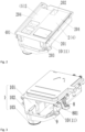
Fig. 1 is a schematic structural diagram of a dispensing device according to an example of the invention; -
Fig. 2 is a schematic structural diagram of an interior of a dispensing device according to an example of the invention; -
Fig. 3 is a schematic structural diagram of a housing of a dispensing device according to an example of the invention; -
Fig. 4 is a schematic structural diagram of dispensing compartments of a dispensing device according to an example of the invention; -
Fig. 5 is a schematic diagram of a connecting structure of a first dispensing compartment and a lower housing of a dispensing device according to an example of the invention; -
Fig. 6 is a schematic diagram of a connecting structure of a second dispensing compartment and a housing of a dispensing device according to an example of the invention; -
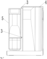
Fig. 7 is a schematic structural diagram of a first dispensing compartment and a second dispensing compartment of a dispensing device according to an example of the invention; -
Fig. 8 is a schematic structural diagram of a first dispensing compartment of a dispensing device according to an example of the invention; -
Fig. 9 is a schematic structural diagram of a second dispensing compartment of a dispensing device according to an example of the invention; -
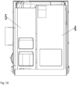
Fig. 10 is a schematic diagram of a first state of a first dispensing compartment and a second dispensing compartment of a dispensing device according to an example of the invention; -
Fig. 11 is a schematic diagram of a second state of a first dispensing compartment and a second dispensing compartment of a dispensing device according to an example of the invention; -
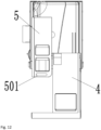
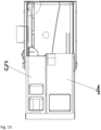
Fig. 12 is a schematic diagram of a third state of a first dispensing compartment and a second dispensing compartment of a dispensing device according to an example of the invention; and -
Fig. 13 is a schematic diagram of a fourth state of a first dispensing compartment and a second dispensing compartment of a dispensing device according to an example of the invention. - Specific embodiments of the invention will be described in detail below in conjunction with the accompanying drawings. It should be understood that the specific embodiments described here are merely illustrative of the invention and are not intended to limit the invention.
- In this disclosure, unless otherwise stated, directional words such as "inside" or "outside" are used to indicate "inside" or "outside" relative to a contour of a corresponding part. In addition, the terms such as "first" and "second" used in the disclosure are used to distinguish one element from another, and are not sequential or important. In addition, when the following descriptions involve the accompanying drawings, unless otherwise specified, the same reference numeral in different accompanying drawings denotes the same or a similar element. The above definitions are only used to explain and illustrate the invention, and should not be construed as limitations on the invention.
- For a wide diversity of dispensing options, a dispensing device of a laundry treatment apparatus is generally provided with a plurality of compartments in one box, into which different detergent can be dispensed. When in use, the box is pulled out and a required compartment is selected to dispense the laundry liquid. In daily use, only one of the compartments is used by a user habitually or preferably, while remaining chambers are often unused. In this case, if all the compartments are pulled out at once, the user needs to identify the compartment or dispensing port to be used, and also has to target at the dispensing port when dispensing the laundry liquid, to avoid mistaken dispensing, which is inconvenient to operate. With many compartments, the box occupies large external space after being pulled out, and is inconvenient to operate in a small space.
- As shown in
Figs. 1-13 , a first aspect of the invention provides a dispensing device. The dispensing device includes a housing 1 and a plurality of dispensing compartments 2. The housing 1 includes acavity 101, aninsertion port 102 in communication with thecavity 101, and a releasingport 103 configured to release a to-be-dispensed agent in the dispensing device. The plurality of dispensingcompartments 2 are all connected to the housing 1 and are capable of being at least partially inserted into thecavity 101 or at least partially pulled out from thecavity 101 through theinsertion port 102. The dispensing compartments 2 is provided with a dispensingport 201 and a dischargingport 202. The dischargingport 202 is in direct or indirect communication with thecavity 101. The plurality of dispensingcompartments 2 are configured in such a way that after one of the dispensing compartments 2 is pulled out from thecavity 101 for a first predetermined distance, the one of the dispensing compartments 2 is capable of pulling out at least one of remainingdispensing compartments 2 for a second predetermined distance from thecavity 101 by means of alinkage structure 3. The dispensingport 201 of the one of the dispensingcompartments 2 at the first predetermined distance is at least partially located outside the housing 1. The dispensingport 201 of the at least one of the remainingdispensing compartments 2 at the second predetermined distance is at least partially located outside the housing 1, and/or the at least one of the remainingdispensing compartments 2 at the second predetermined distance is capable of being continuously pulled out from thecavity 101 under the action of an external force. - In a dispensing process, the one of the dispensing compartments 2 is pulled out from the
cavity 101 for the first predetermined distance by a user. In this case, the one of the dispensing compartments 2 is located at a first position, at least part of the dispensingport 201 of the one of the dispensing compartments 2 is located outside thecavity 101, and the dispensingport 201 of the remainingdispensing compartments 2 are still located in thecavity 101 or cannot be pulled out from thecavity 101 by the external force. The to-be-dispensed agent may be dispensed into the dispensingport 201 of thedispensing compartment 2 at the first position by the user. If the remainingdispensing compartments 2 need to be used later, thedispensing compartment 2 at the first position may be continuously pulled out, such that at least one of remainingdispensing compartments 2 may be pulled out from thecavity 101 for the second predetermined distance through thelinkage structure 3, and at least one of the remainingdispensing compartments 2 may be placed at a second position. In this case, the dispensingport 201 of thedispensing compartment 2 at the second position may be at least partially located outside the housing 1, or may be continuously pulled out from thecavity 101 under the action of the external force. In this way, the to-be-dispensed agent may be dispensed to the at least one of the remainingdispensing compartments 2 by the user. In this way, onedispensing compartment 2 ormore dispensing compartments 2 may be selected and pulled out by the user as required. Thedispensing compartment 2 pulled firstly may be set as adispensing compartment 2 frequently used according to daily usage habits or preferences of the user, such as an automatic dispensing compartment. In addition, the situation that after compartments are pulled out all at once in the related art, the user needs to identify the compartment required and avoid misoperation can be prevented, and daily operations by the user can be facilitated. In addition, when not all the dispensing compartments 2 need to be pulled out, and for instance, when thedispensing compartment 2 frequently used is pulled out firstly according to the preference of the user, less external space is occupied. - The first predetermined distance and the second predetermined distance are designed according to sizes of actual application products, such as the dispensing device and a laundry treatment apparatus. The first predetermined distance and the second predetermined distance may be the same or not, which is not specifically limited by the invention.
- In some embodiments of the invention, as shown in
Figs. 2 ,4 and7 , thedispensing compartment 2 firstly pulled out from thecavity 101 for the first predetermined distance may be afirst dispensing compartment 4, the at least one of the remainingdispensing compartments 2 may include asecond dispensing compartment 5, and thefirst dispensing compartment 4 and thesecond dispensing compartment 5 are arranged in parallel. Thelinkage structure 3 includes afirst matching part 6 arranged on thefirst dispensing compartment 4 and asecond matching part 7 arranged on thesecond dispensing compartment 5. Thefirst matching part 6 at the first predetermined distance is capable of abutting against thesecond matching part 7, such that thesecond dispensing compartment 5 may be driven to move for the second predetermined distance. - The
first dispensing compartment 4 and thesecond dispensing compartment 5 may be set according to preferences or usage habits of users. For instance, the dischargingport 202 of thefirst dispensing compartment 4 may be configured to allow a suction member to penetrate to suck a to-be-dispensed agent in thefirst dispensing compartment 4, that is, thefirst dispensing compartment 4 may be an automatic dispensing compartment commonly used by the users. With an intelligent design of the automatic dispensing compartment, the automatic dispensing compartment is firstly pulled out by a user, so as to satisfy a preference of the user. Thesecond dispensing compartment 5 has at least one dispensingspace 502, each dispensingspace 502 has a dispensingport 201 and a dischargingport 202, and the dischargingport 202 is located on a bottom wall of thesecond dispensing compartment 5. Different dispensingspaces 502 may be configured to allow different to-be-dispensed agents, such as a softener and a detergent, to be dispensed to. Thesecond dispensing compartment 5 is a manual dispensing compartment seldom used by the user. When thefirst dispensing compartment 4 is pulled out from thecavity 101 for the first predetermined distance, thefirst matching part 6 just abuts against thesecond matching part 7. In this case, the dispensingport 201 of thefirst dispensing compartment 4 is exposed, and the user may only conduct a dispensing operation on thefirst dispensing compartment 4. When a dispensing operation needs to be conducted on thesecond dispensing compartment 5, thefirst dispensing compartment 4 may be pulled out continuously, such that thesecond dispensing compartment 5 is pulled out from thecavity 101 for the second predetermined distance under the action of thefirst matching part 6 and thesecond matching part 7. In this case, the dispensingport 201 of thesecond dispensing compartment 5 may be moved out from thecavity 101, or thesecond dispensing compartment 5 may be continuously pulled out under the action of an external force until the dispensingport 201 of thesecond dispensing compartment 5 is moved out from thecavity 101, such that the dispensing operation may be conducted on thesecond dispensing compartment 5 conveniently by the user. The suction member may be of any suitable suction structure, and for instance, composed of a suction pump and a suction tube in communication with thefirst dispensing compartment 4. The suction pump may pump the to-be-dispensed agent in thefirst dispensing compartment 4 to a corresponding dispensing position by means of the suction tube. - The
first dispensing compartment 4 and thesecond dispensing compartment 5 may have various arrangement forms. Thesecond dispensing compartment 5 may be arranged at any position around thefirst dispensing compartment 4. For instance, thesecond dispensing compartment 5 is located at a bottom, a top or a side of thefirst dispensing compartment 4, which is not limited by the invention. In the invention, thesecond dispensing compartment 5 is located at one side of thefirst dispensing compartment 4 in a horizontal direction, for instance. - As shown in
Figs. 7 and8 , thefirst matching part 6 may include afirst protrusion 601, and thefirst protrusion 601 is provided with afirst matching surface 602 facing thesecond matching part 7. In order to facilitate matching of thefirst matching part 6 with thesecond matching part 7, thesecond matching part 7 may include asecond protrusion 701, and thesecond protrusion 701 is provided with asecond matching surface 702 facing thefirst matching part 6. Thefirst protrusion 601 is arranged opposite thesecond protrusion 701, such that at least partial zones of thefirst matching surface 602 and thesecond matching surface 702 may abut against each other. In addition, in order to ensure an abutting effect and own strength of thefirst protrusion 601 and thesecond protrusion 701, thefirst protrusion 601 may be configured to be a first plate body, thefirst matching surface 602 is formed on the first plate body, and one side of the first plate body facing away from thefirst matching surface 602 is provided with a first reinforcingrib 603; and/or, thesecond protrusion 701 may be configured to be a second plate body, thesecond matching surface 702 is formed on the second plate body, and one side of the second plate body facing away from thesecond matching surface 702 is provided with a second reinforcingrib 703. A plate structure increases a contact area of the matching surfaces, such that stability of thefirst matching part 6 and thesecond matching part 7 after abutting can be ensured. A plurality of first reinforcingribs 603 and/or second reinforcingribs 703 are arranged and uniformly distributed on the plate bodies, such that strength of the plate structure can be improved. - In some embodiments not illustrated, the
first matching part 6 and thesecond matching part 7 may also be arranged in other forms. For instance, thefirst matching part 6 may directly abut against an outer wall surface of thesecond dispensing compartment 5, that is, part of the outer wall surface of thesecond dispensing compartment 5 may be used as thesecond matching part 7. Alternatively, thesecond matching part 7 may directly abut against an outer wall surface of thefirst dispensing compartment 4, that is, part of the outer wall surface of thefirst dispensing compartment 4 may be used as thefirst matching part 6, such that one of the dispensingcompartments 2 drives anotheradjacent dispensing compartment 2 to move. - In some embodiments not illustrated, the
first matching part 6 and thesecond matching part 7 may also have various configurations and matching modes. For instance, one of thefirst matching part 6 and thesecond matching part 7 may be configured to be a plate body or a block structure, and the other one may be configured to be a recess. The plate body or the block structure may reciprocate in the recess until the plate body or the block structure abuts against an end of the recess so as to achieve an effect of pushing thedispensing compartment 2 to move. - In some embodiments, as shown in
Figs. 1 ,2 ,4 and 5 , thefirst dispensing compartment 4 is provided with afirst handle part 401. Thefirst handle part 401 is capable of covering theinsertion port 102 and shields thesecond dispensing compartment 5. For instance, when thefirst dispensing compartment 4 is in a storage state, an unused state or an unpulled-out state, thefirst handle part 401 may cover theinsertion port 102. In this way, thefirst dispensing compartment 4 may be firstly pulled out by directly pulling thefirst handle part 401 without identification of a user, and then thesecond dispensing compartment 5 may be driven to move by thefirst dispensing compartment 4. In addition, after thefirst handle part 401 covers theinsertion port 102, an overall appearance of the dispensing device or a laundry treatment apparatus using the dispensing device of the invention can be improved. - In order to facilitate an operation of pulling the
second dispensing compartment 5 out from thecavity 101, as shown inFigs. 11 and12 , thesecond dispensing compartment 5 may be provided with asecond handle part 501. Thesecond handle part 501 at the second predetermined distance is at least partially located outside the housing 1. In this way, after thesecond dispensing compartment 5 is pulled out from thecavity 101 for the second predetermined distance, if an exposed space of the dispensingport 201 of thesecond dispensing compartment 5 is small, or the dispensingport 201 is not exposed from thecavity 101, the user may continuously pull thesecond dispensing compartment 5 out from thecavity 101 by means of thesecond handle part 501. Thesecond handle part 501 may be configured as a holding port that runs through thesecond dispensing compartment 5 in a vertical direction, such that thesecond handle part 501 has a simple overall structure and a small occupied space, and may be more conveniently operated by the user. For instance, the user only needs to insert a hand into the holding port from top to bottom. - In some embodiments of the invention, as shown in
Figs. 4 and7 , at least part of an inner side wall surface of thefirst dispensing compartment 4 extends obliquely towards an inner bottom surface of thefirst dispensing compartment 4 relative to a vertical direction. The dischargingport 202 is located on a top wall of thefirst dispensing compartment 4 and arranged opposite the inner bottom surface. In this way, the to-be-dispensed agent located in thefirst dispensing compartment 4 may be gathered in one place, and may be conveniently pumped away later. Clearly, in the dispensing space of thesecond dispensing compartment 5, an inner side wall surface of the dispensing space may also extend obliquely towards an inner bottom surface of thesecond dispensing compartment 5 relative to a vertical direction, such that the to-be-dispensed agent may conveniently flow out from the dispensing space. - In addition, in order to ensure sealing and aesthetics of the
dispensing compartment 2, atop cover 204 may be arranged on a top of thedispensing compartment 2, and an openable or normally open dispensing region may be provided on thetop cover 204 to form the dispensingport 201. - In some embodiments, as shown in
Figs. 1-3 ,5 and6 , the housing 1 includes anupper housing 8 and alower housing 9 butted against each other. Theupper housing 8 and thelower housing 9 define thecavity 101 and theinsertion port 102. A periphery of thelower housing 9 is provided with aslot 10 matched with theupper housing 8 in an inserted manner. At least part of theslot 10 forms a guidinggroove 11 configured to support and guide movement of the plurality of dispensing compartments 2. Theslot 10 may not only be configured to connect theupper housing 8 to thelower housing 9, but also facilitate sliding of the dispensing compartments 2, and a connecting structure and a sliding structure need not to be separately arranged, such that less space is occupied while a housing structure is simplified. - The guiding
groove 11 includes aninner wall 1101 and anouter wall 1102 that extend side by side, and a connectingwall 1103 connected between theinner wall 1101 and theouter wall 1102. Theupper housing 8 is provided with a U-shapedclamping groove part 801 into which theouter wall 1102 is inserted. Thedispensing compartment 2 adjacent to the guidinggroove 11 is provided with a slidingrail 203 inserted between theinner wall 1101 and the clampinggroove part 801. Theupper housing 8 and thelower housing 9 are connected by inserting theouter wall 1102 into the clampinggroove part 801. In addition, in order to ensure stability after theupper housing 8 and thelower housing 9 are connected to each other, connecting structures matched with each other may be arranged on two sides of theupper housing 8 and thelower housing 9. After the slidingrail 203 is inserted between theinner wall 1101 and the clampinggroove part 801, thedispensing compartment 2 may reciprocate in a pulling or inserting direction of thedispensing compartment 2 on the connectingwall 1103 by means of the slidingrail 203. Clearly, in order to prevent thedispensing compartment 2 from slipping out of thecavity 101, the slidingrail 203 and the guidinggroove 11 may be separately provided with limiting structures, and the two limiting structures may abut against each other after the dispensing compartment moves to an extreme position away from thecavity 101, such that thedispensing compartment 2 may be limited. - In some embodiments of the invention, the
upper housing 8 may be further provided with a guidingpart 802 extending between any two adjacent of the dispensing compartments 2, and at least one of the two adjacent of the dispensing compartments 2 is movably connected to the guidingpart 802. Through the guidingpart 802, thedispensing compartment 2 may have an extra supporting and guiding zone, such that stability of the dispensingcompartments 2 during movement can be ensured. - A second aspect of the invention provides a laundry treatment apparatus. The laundry treatment apparatus includes the above dispensing device. The laundry treatment apparatus includes a case. The dispensing device is connected to any one of side wall surfaces of the case and arranged adjacent to a side edge of the side wall surface on which the dispensing device is located. The one of the dispensing compartments 2 is arranged farther away from the side edge than any one of the remaining dispensing compartments 2. With the
first dispensing compartment 4 and thesecond dispensing compartment 5 as an instance, compared with thesecond dispensing compartment 5, thefirst dispensing compartment 4 farther away from the side edge of the laundry treatment apparatus is more commonly used by the user. Most laundry treatment apparatuses are placed against a wall. The arrangement mode may make thefirst dispensing compartment 4 far away from the wall, such that an operating space for the user to dispense the agent cannot be influenced by the wall, and the to-be-dispensed agent may be conveniently dispensed to thedispensing compartment 2. The laundry treatment apparatus may be, for instance, a washer. The washer may be, for instance, a drum washing machine or a pulsator washing machine, which is not limited by the invention. - To sum up, the invention describes a usage mode of the dispensing device including the
first dispensing compartment 4 and thesecond dispensing compartment 5, for instance. For instance, in normal use, the user may firstly pull thefirst dispensing compartment 4 out from thecavity 101 for the first predetermined distance by means of thefirst handle part 401, such that the dispensingport 201 of thefirst dispensing compartment 4 may be pulled out from thecavity 101, and the to-be-dispensed agent may be dispensed to thefirst dispensing compartment 4 by the user. If the remainingdispensing compartments 2 are not need to be used later, thefirst dispensing compartment 4 may be pushed back into thecavity 101 after dispensing, such that the dispensing operation may be completed. If the user still needs to use the remainingdispensing compartments 2, such as thesecond dispensing compartment 5, thefirst dispensing compartment 4 may be continuously pulled out, and thefirst matching part 6 located on thefirst dispensing compartment 4 and thesecond matching part 7 abut against each other. Thefirst matching part 6 may push thesecond matching part 7 while thefirst dispensing compartment 4 continuously moves, such that thesecond dispensing compartment 5 connected to thesecond matching part 7 may be pulled out from thecavity 101 for the second predetermined distance. In this case, the user may conduct different operations according to different conditions. If thesecond dispensing compartment 5 is at least partially located outside the housing 1 after being pulled out from thecavity 101 for the second predetermined distance, that is, thesecond handle part 501 is exposed from thecavity 101, the user may pull the dispensingport 201 of thesecond dispensing compartment 5 out from thecavity 101 by means of thesecond handle part 501 and pour the to-be-dispensed agent into the second dispensing compartment. If the dispensingport 201 of the second dispensing compartment is exposed after thesecond dispensing compartment 5 is pulled out from thecavity 101 for the second predetermined distance, the user may directly pour the to-be-dispensed agent into the dispensingport 201, and then push thefirst dispensing compartment 4 and thesecond dispensing compartment 5 back into thecavity 101 after dispensing, such that the entire dispensing operation may be completed. In this way, it is ensured that the plurality of dispensingcompartments 2 may be pulled out from thecavity 101 of the dispensing device in sections, such that the user may select and pull out onedispensing compartment 2 ormore dispensing compartments 2 as required. Thedispensing compartment 2 pulled firstly may be set as adispensing compartment 2 frequently used according to daily usage habits or preferences of the user, such as an automatic dispensing compartment. In addition, the situation that after compartments are pulled out all at once in the related art, the user needs to identify the chamber required and avoid misoperation can be prevented, and daily operations by the user can be facilitated. In addition, when not all the dispensing compartments 2 need to be pulled out, and for instance, when thedispensing compartment 2 frequently used is pulled out firstly according to the preference of the user, less external space is occupied. - The preferred embodiments of the invention are described in detail above with reference to the accompanying drawings. However, the invention is not limited to specific details of the embodiments described above. Within the scope of the technical concept of the invention, various simple modifications can be made to the technical solution of the invention, and these simple modifications all fall within the protection scope of the invention.
- It should also be noted that various specific technical features described in the above specific embodiments may be combined in any suitable manner, without contradiction. In order to avoid unnecessary repetition, various possible combinations will not be described separately in the invention.
Claims (15)
- A dispensing device, comprising:a housing (1) comprising a cavity (101), and an insertion port (102) and a releasing port (103) that are in communication with the cavity (101); anda plurality of dispensing compartments (2), wherein the plurality of dispensing compartments (2) are all connected to the housing (1) and are capable of being at least partially inserted into the cavity (101) or at least partially pulled out from the cavity (101) through the insertion port (102), the dispensing compartments (2) comprise a dispensing port (201) and a discharging port (202), and the discharging port (202) is in direct or indirect communication with the cavity,wherein the plurality of dispensing compartments (2) are configured in such a way that after one of the dispensing compartments (2) is pulled out from the cavity (101) for a first predetermined distance, the one of the dispensing compartments (2) is capable of pulling out at least one of remaining dispensing compartments (2) for a second predetermined distance from the cavity (101) by means of a linkage structure (3), the dispensing port (201) of the one of the dispensing compartments (2) at the first predetermined distance is at least partially located outside the housing (1),wherein the dispensing port (201) of the at least one of the remaining dispensing compartments (2) at the second predetermined distance is at least partially located outside the housing (1), and/or the at least one of the remaining dispensing compartments (2) at the second predetermined distance is capable of being continuously pulled out from the cavity (101) under the action of an external force.
- The dispensing device according to claim 1, wherein the one of the dispensing compartments (2) is a first dispensing compartment (4), the at least one of the remaining dispensing compartments (2) comprises a second dispensing compartment (5), the first dispensing compartment (4) and the second dispensing compartment (5) are arranged in parallel, the linkage structure (3) comprises a first matching part (6) located on the first dispensing compartment (4) and a second matching part (7) located on the second dispensing compartment (5), and the first matching part (6) at the first predetermined distance is capable of abutting against the second matching part (7), so as to be able to drive the second dispensing compartment (5) to move for the second predetermined distance.
- The dispensing device according to claim 2, wherein the first matching part (6) comprises a first protrusion (601), and the first protrusion (601) comprises a first matching surface (602) facing the second matching part (7); and/or,
the second matching part (7) comprises a second protrusion (701), and the second protrusion (701) comprises a second matching surface (702) facing the first matching part (6). - The dispensing device according to claim 3, wherein the first protrusion (601) is configured to be a first plate body, the first matching surface (602) is formed on the first plate body, and a first reinforcing rib (603) is on a side of the first plate body facing away from the first matching surface (602); and/or,
the second protrusion (701) is configured to be a second plate body, the second matching surface (702) is formed on the second plate body, and a second reinforcing rib (703) is on a side of the second plate body facing away from the second matching surface (702). - The dispensing device according to any one of claims 2-4, wherein the first dispensing compartment (4) comprises a first handle part (401), and the first handle part (401) is capable of covering the insertion port (102) and shields the second dispensing compartment (5).
- The dispensing device according to any one of claims 2-5, wherein the second dispensing compartment (5) comprises a second handle part (501), and the second handle part (501) at the second predetermined distance is at least partially located outside the housing (1).
- The dispensing device according to claim 6, wherein the second handle part (501) is configured as a holding port that runs through the second dispensing compartment (5) in a vertical direction.
- The dispensing device according to any one of claims 2-7, wherein the discharging port (202) of the first dispensing compartment (4) is configured to allow a suction member to penetrate to suck a to-be-dispensed agent in the first dispensing compartment (4).
- The dispensing device according to claim 8, wherein at least part of an inner side wall surface of the first dispensing compartment (4) extends obliquely towards an inner bottom surface of the first dispensing compartment (4) relative to a vertical direction, and the discharging port (202) is located on a top wall of the first dispensing compartment (4) and arranged opposite the inner bottom surface.
- The dispensing device according to any one of claims 2-9, wherein the second dispensing compartment (5) comprises at least one dispensing space (502), the at least one dispensing space (502) each comprises the dispensing port (201) and the discharging port (202), and the discharging port (202) is located on a bottom wall of the second dispensing compartment (5).
- The dispensing device according to any one of claims 1-10, wherein the housing (1) comprises an upper housing (8) and a lower housing (9) butted against each other, the upper housing (8) and the lower housing (9) define the cavity (101) and the insertion port (102), a slot (10) matched with the upper housing (8) in an inserted manner is on a periphery of the lower housing (9), and at least part of the slot (10) forms a guiding groove (11) configured to support and guide movement of the plurality of dispensing compartments (2).
- The dispensing device according to claim 11, wherein the guiding groove (11) comprises an inner wall (1101) and an outer wall (1102) that extend side by side, and a connecting wall (1103) connected between the inner wall (1101) and the outer wall (1102), the upper housing (8) comprises a U-shaped clamping groove part (801) into which the outer wall (1102) is inserted, and the dispensing compartment (2) adjacent to the guiding groove (11) comprises a sliding rail (203) inserted between the inner wall (1101) and the clamping groove part (801).
- The dispensing device according to claim 12, wherein the upper housing (8) comprises a guiding part (802) extending between any two adjacent of the dispensing compartments (2), and at least one of the two adjacent of the dispensing compartments (2) is movably connected to the guiding part (802).
- A laundry treatment apparatus, comprising the dispensing device according to any one of claims 1-13.
- The laundry treatment apparatus according to claim 14, comprising a case, wherein the dispensing device is connected to any one of side wall surfaces of the case and arranged adjacent to a side edge of the side wall surface on which the dispensing device is located, and the one of the dispensing compartments (2) is arranged farther away from the side edge than any one of the remaining dispensing compartments (2).
Applications Claiming Priority (1)
| Application Number | Priority Date | Filing Date | Title |
|---|---|---|---|
| CN202311597807.3A CN120042040A (en) | 2023-11-27 | 2023-11-27 | Throwing device and clothes treatment equipment |
Publications (1)
| Publication Number | Publication Date |
|---|---|
| EP4560065A1 true EP4560065A1 (en) | 2025-05-28 |
Family
ID=93562572
Family Applications (1)
| Application Number | Title | Priority Date | Filing Date |
|---|---|---|---|
| EP24212881.7A Pending EP4560065A1 (en) | 2023-11-27 | 2024-11-14 | Dispensing device and laundry treatment apparatus |
Country Status (2)
| Country | Link |
|---|---|
| EP (1) | EP4560065A1 (en) |
| CN (1) | CN120042040A (en) |
Citations (3)
| Publication number | Priority date | Publication date | Assignee | Title |
|---|---|---|---|---|
| EP1842953A2 (en) * | 2006-04-07 | 2007-10-10 | IAR-SILTAL S.p.A. | Laundry washing machine with a device for dosing and/or distributing detergent and the like |
| CN104404740A (en) * | 2014-11-20 | 2015-03-11 | 合肥荣事达三洋电器股份有限公司 | Detergent feeding device for washing machine |
| WO2019201149A1 (en) * | 2018-04-20 | 2019-10-24 | 青岛海尔滚筒洗衣机有限公司 | Clothing treatment agent dispensing assembly for clothing treatment apparatus, and clothing treatment apparatus |
-
2023
- 2023-11-27 CN CN202311597807.3A patent/CN120042040A/en active Pending
-
2024
- 2024-11-14 EP EP24212881.7A patent/EP4560065A1/en active Pending
Patent Citations (3)
| Publication number | Priority date | Publication date | Assignee | Title |
|---|---|---|---|---|
| EP1842953A2 (en) * | 2006-04-07 | 2007-10-10 | IAR-SILTAL S.p.A. | Laundry washing machine with a device for dosing and/or distributing detergent and the like |
| CN104404740A (en) * | 2014-11-20 | 2015-03-11 | 合肥荣事达三洋电器股份有限公司 | Detergent feeding device for washing machine |
| WO2019201149A1 (en) * | 2018-04-20 | 2019-10-24 | 青岛海尔滚筒洗衣机有限公司 | Clothing treatment agent dispensing assembly for clothing treatment apparatus, and clothing treatment apparatus |
Also Published As
| Publication number | Publication date |
|---|---|
| CN120042040A (en) | 2025-05-27 |
Similar Documents
| Publication | Publication Date | Title |
|---|---|---|
| US8171757B2 (en) | Dispensing system for liquid or viscous treating agents for use in a washing machine, and washing machine | |
| KR101698310B1 (en) | Detergent supply apparatus and washing machine having the same | |
| EP2374926B1 (en) | Washing machine | |
| EP2905369A1 (en) | Laundry treating apparatus | |
| US12168846B2 (en) | Laundry treating apparatus | |
| EP1795643A1 (en) | Detergent supply apparatus for a washing machine | |
| JP7723472B2 (en) | Clothes treatment equipment | |
| KR102788012B1 (en) | Storage container and clothes treating machine include the same | |
| KR101558903B1 (en) | Washing machine and drawer assembly thereof | |
| US20200232149A1 (en) | Washing machine | |
| EP4560065A1 (en) | Dispensing device and laundry treatment apparatus | |
| JP7522570B2 (en) | Clothes Processing Equipment | |
| US11898293B2 (en) | Laundry treating apparatus | |
| RU2744859C1 (en) | Drawer and clothing treatment machine containing such drawer | |
| AU2021236573B2 (en) | Laundry treating apparatus | |
| KR101474433B1 (en) | Cleaning material feeder for washer | |
| CN114293347B (en) | Clothes treating apparatus | |
| JP7854265B2 (en) | Clothing processing equipment | |
| DK2881510T3 (en) | Washing machine with detergent storage containers | |
| JP7746500B2 (en) | washing machine | |
| EP4556618A1 (en) | Washing machine with an automatic dosing system | |
| JP2002051959A (en) | Draw out type dishwasher | |
| JP7652635B2 (en) | washing machine | |
| KR20060120925A (en) | Detergent supply of drum washing machine | |
| RU2293151C1 (en) | Detergent feeding unit for washing machine |
Legal Events
| Date | Code | Title | Description |
|---|---|---|---|
| PUAI | Public reference made under article 153(3) epc to a published international application that has entered the european phase |
Free format text: ORIGINAL CODE: 0009012 |
|
| STAA | Information on the status of an ep patent application or granted ep patent |
Free format text: STATUS: REQUEST FOR EXAMINATION WAS MADE |
|
| 17P | Request for examination filed |
Effective date: 20241114 |
|
| AK | Designated contracting states |
Kind code of ref document: A1 Designated state(s): AL AT BE BG CH CY CZ DE DK EE ES FI FR GB GR HR HU IE IS IT LI LT LU LV MC ME MK MT NL NO PL PT RO RS SE SI SK SM TR |
|
| STAA | Information on the status of an ep patent application or granted ep patent |
Free format text: STATUS: EXAMINATION IS IN PROGRESS |
|
| 17Q | First examination report despatched |
Effective date: 20260324 |