EP4560038A1 - High strength steel sheet, method for producing same, member, and method for producing same - Google Patents
High strength steel sheet, method for producing same, member, and method for producing same Download PDFInfo
- Publication number
- EP4560038A1 EP4560038A1 EP23859901.3A EP23859901A EP4560038A1 EP 4560038 A1 EP4560038 A1 EP 4560038A1 EP 23859901 A EP23859901 A EP 23859901A EP 4560038 A1 EP4560038 A1 EP 4560038A1
- Authority
- EP
- European Patent Office
- Prior art keywords
- steel sheet
- amount
- rolled steel
- cold rolled
- temperature
- Prior art date
- Legal status (The legal status is an assumption and is not a legal conclusion. Google has not performed a legal analysis and makes no representation as to the accuracy of the status listed.)
- Pending
Links
Images

Classifications
-
- C—CHEMISTRY; METALLURGY
- C21—METALLURGY OF IRON
- C21D—MODIFYING THE PHYSICAL STRUCTURE OF FERROUS METALS; GENERAL DEVICES FOR HEAT TREATMENT OF FERROUS OR NON-FERROUS METALS OR ALLOYS; MAKING METAL MALLEABLE, e.g. BY DECARBURISATION OR TEMPERING
- C21D9/00—Heat treatment, e.g. annealing, hardening, quenching or tempering, adapted for particular articles; Furnaces therefor
- C21D9/46—Heat treatment, e.g. annealing, hardening, quenching or tempering, adapted for particular articles; Furnaces therefor for sheet metals
-
- C—CHEMISTRY; METALLURGY
- C21—METALLURGY OF IRON
- C21D—MODIFYING THE PHYSICAL STRUCTURE OF FERROUS METALS; GENERAL DEVICES FOR HEAT TREATMENT OF FERROUS OR NON-FERROUS METALS OR ALLOYS; MAKING METAL MALLEABLE, e.g. BY DECARBURISATION OR TEMPERING
- C21D6/00—Heat treatment of ferrous alloys
- C21D6/005—Heat treatment of ferrous alloys containing Mn
-
- C—CHEMISTRY; METALLURGY
- C21—METALLURGY OF IRON
- C21D—MODIFYING THE PHYSICAL STRUCTURE OF FERROUS METALS; GENERAL DEVICES FOR HEAT TREATMENT OF FERROUS OR NON-FERROUS METALS OR ALLOYS; MAKING METAL MALLEABLE, e.g. BY DECARBURISATION OR TEMPERING
- C21D8/00—Modifying the physical properties of ferrous metals or ferrous alloys by deformation combined with, or followed by, heat treatment
- C21D8/02—Modifying the physical properties of ferrous metals or ferrous alloys by deformation combined with, or followed by, heat treatment during manufacturing of plates or strips
-
- C—CHEMISTRY; METALLURGY
- C21—METALLURGY OF IRON
- C21D—MODIFYING THE PHYSICAL STRUCTURE OF FERROUS METALS; GENERAL DEVICES FOR HEAT TREATMENT OF FERROUS OR NON-FERROUS METALS OR ALLOYS; MAKING METAL MALLEABLE, e.g. BY DECARBURISATION OR TEMPERING
- C21D8/00—Modifying the physical properties of ferrous metals or ferrous alloys by deformation combined with, or followed by, heat treatment
- C21D8/02—Modifying the physical properties of ferrous metals or ferrous alloys by deformation combined with, or followed by, heat treatment during manufacturing of plates or strips
- C21D8/0221—Modifying the physical properties of ferrous metals or ferrous alloys by deformation combined with, or followed by, heat treatment during manufacturing of plates or strips characterised by the working steps
- C21D8/0226—Hot rolling
-
- C—CHEMISTRY; METALLURGY
- C21—METALLURGY OF IRON
- C21D—MODIFYING THE PHYSICAL STRUCTURE OF FERROUS METALS; GENERAL DEVICES FOR HEAT TREATMENT OF FERROUS OR NON-FERROUS METALS OR ALLOYS; MAKING METAL MALLEABLE, e.g. BY DECARBURISATION OR TEMPERING
- C21D8/00—Modifying the physical properties of ferrous metals or ferrous alloys by deformation combined with, or followed by, heat treatment
- C21D8/02—Modifying the physical properties of ferrous metals or ferrous alloys by deformation combined with, or followed by, heat treatment during manufacturing of plates or strips
- C21D8/0221—Modifying the physical properties of ferrous metals or ferrous alloys by deformation combined with, or followed by, heat treatment during manufacturing of plates or strips characterised by the working steps
- C21D8/0236—Cold rolling
-
- C—CHEMISTRY; METALLURGY
- C21—METALLURGY OF IRON
- C21D—MODIFYING THE PHYSICAL STRUCTURE OF FERROUS METALS; GENERAL DEVICES FOR HEAT TREATMENT OF FERROUS OR NON-FERROUS METALS OR ALLOYS; MAKING METAL MALLEABLE, e.g. BY DECARBURISATION OR TEMPERING
- C21D8/00—Modifying the physical properties of ferrous metals or ferrous alloys by deformation combined with, or followed by, heat treatment
- C21D8/02—Modifying the physical properties of ferrous metals or ferrous alloys by deformation combined with, or followed by, heat treatment during manufacturing of plates or strips
- C21D8/0247—Modifying the physical properties of ferrous metals or ferrous alloys by deformation combined with, or followed by, heat treatment during manufacturing of plates or strips characterised by the heat treatment
- C21D8/0273—Final recrystallisation annealing
-
- C—CHEMISTRY; METALLURGY
- C22—METALLURGY; FERROUS OR NON-FERROUS ALLOYS; TREATMENT OF ALLOYS OR NON-FERROUS METALS
- C22C—ALLOYS
- C22C38/00—Ferrous alloys, e.g. steel alloys
- C22C38/001—Ferrous alloys, e.g. steel alloys containing N
-
- C—CHEMISTRY; METALLURGY
- C22—METALLURGY; FERROUS OR NON-FERROUS ALLOYS; TREATMENT OF ALLOYS OR NON-FERROUS METALS
- C22C—ALLOYS
- C22C38/00—Ferrous alloys, e.g. steel alloys
- C22C38/002—Ferrous alloys, e.g. steel alloys containing In, Mg, or other elements not provided for in one single group C22C38/001 - C22C38/60
-
- C—CHEMISTRY; METALLURGY
- C22—METALLURGY; FERROUS OR NON-FERROUS ALLOYS; TREATMENT OF ALLOYS OR NON-FERROUS METALS
- C22C—ALLOYS
- C22C38/00—Ferrous alloys, e.g. steel alloys
- C22C38/005—Ferrous alloys, e.g. steel alloys containing rare earths, i.e. Sc, Y, Lanthanides
-
- C—CHEMISTRY; METALLURGY
- C22—METALLURGY; FERROUS OR NON-FERROUS ALLOYS; TREATMENT OF ALLOYS OR NON-FERROUS METALS
- C22C—ALLOYS
- C22C38/00—Ferrous alloys, e.g. steel alloys
- C22C38/008—Ferrous alloys, e.g. steel alloys containing tin
-
- C—CHEMISTRY; METALLURGY
- C22—METALLURGY; FERROUS OR NON-FERROUS ALLOYS; TREATMENT OF ALLOYS OR NON-FERROUS METALS
- C22C—ALLOYS
- C22C38/00—Ferrous alloys, e.g. steel alloys
- C22C38/02—Ferrous alloys, e.g. steel alloys containing silicon
-
- C—CHEMISTRY; METALLURGY
- C22—METALLURGY; FERROUS OR NON-FERROUS ALLOYS; TREATMENT OF ALLOYS OR NON-FERROUS METALS
- C22C—ALLOYS
- C22C38/00—Ferrous alloys, e.g. steel alloys
- C22C38/04—Ferrous alloys, e.g. steel alloys containing manganese
-
- C—CHEMISTRY; METALLURGY
- C22—METALLURGY; FERROUS OR NON-FERROUS ALLOYS; TREATMENT OF ALLOYS OR NON-FERROUS METALS
- C22C—ALLOYS
- C22C38/00—Ferrous alloys, e.g. steel alloys
- C22C38/06—Ferrous alloys, e.g. steel alloys containing aluminium
-
- C—CHEMISTRY; METALLURGY
- C22—METALLURGY; FERROUS OR NON-FERROUS ALLOYS; TREATMENT OF ALLOYS OR NON-FERROUS METALS
- C22C—ALLOYS
- C22C38/00—Ferrous alloys, e.g. steel alloys
- C22C38/08—Ferrous alloys, e.g. steel alloys containing nickel
-
- C—CHEMISTRY; METALLURGY
- C22—METALLURGY; FERROUS OR NON-FERROUS ALLOYS; TREATMENT OF ALLOYS OR NON-FERROUS METALS
- C22C—ALLOYS
- C22C38/00—Ferrous alloys, e.g. steel alloys
- C22C38/10—Ferrous alloys, e.g. steel alloys containing cobalt
-
- C—CHEMISTRY; METALLURGY
- C22—METALLURGY; FERROUS OR NON-FERROUS ALLOYS; TREATMENT OF ALLOYS OR NON-FERROUS METALS
- C22C—ALLOYS
- C22C38/00—Ferrous alloys, e.g. steel alloys
- C22C38/14—Ferrous alloys, e.g. steel alloys containing titanium or zirconium
-
- C—CHEMISTRY; METALLURGY
- C22—METALLURGY; FERROUS OR NON-FERROUS ALLOYS; TREATMENT OF ALLOYS OR NON-FERROUS METALS
- C22C—ALLOYS
- C22C38/00—Ferrous alloys, e.g. steel alloys
- C22C38/16—Ferrous alloys, e.g. steel alloys containing copper
-
- C—CHEMISTRY; METALLURGY
- C22—METALLURGY; FERROUS OR NON-FERROUS ALLOYS; TREATMENT OF ALLOYS OR NON-FERROUS METALS
- C22C—ALLOYS
- C22C38/00—Ferrous alloys, e.g. steel alloys
- C22C38/18—Ferrous alloys, e.g. steel alloys containing chromium
- C22C38/34—Ferrous alloys, e.g. steel alloys containing chromium with more than 1.5% by weight of silicon
-
- C—CHEMISTRY; METALLURGY
- C22—METALLURGY; FERROUS OR NON-FERROUS ALLOYS; TREATMENT OF ALLOYS OR NON-FERROUS METALS
- C22C—ALLOYS
- C22C38/00—Ferrous alloys, e.g. steel alloys
- C22C38/18—Ferrous alloys, e.g. steel alloys containing chromium
- C22C38/38—Ferrous alloys, e.g. steel alloys containing chromium with more than 1.5% by weight of manganese
-
- C—CHEMISTRY; METALLURGY
- C22—METALLURGY; FERROUS OR NON-FERROUS ALLOYS; TREATMENT OF ALLOYS OR NON-FERROUS METALS
- C22C—ALLOYS
- C22C38/00—Ferrous alloys, e.g. steel alloys
- C22C38/60—Ferrous alloys, e.g. steel alloys containing lead, selenium, tellurium, or antimony, or more than 0.04% by weight of sulfur
-
- C—CHEMISTRY; METALLURGY
- C23—COATING METALLIC MATERIAL; COATING MATERIAL WITH METALLIC MATERIAL; CHEMICAL SURFACE TREATMENT; DIFFUSION TREATMENT OF METALLIC MATERIAL; COATING BY VACUUM EVAPORATION, BY SPUTTERING, BY ION IMPLANTATION OR BY CHEMICAL VAPOUR DEPOSITION, IN GENERAL; INHIBITING CORROSION OF METALLIC MATERIAL OR INCRUSTATION IN GENERAL
- C23C—COATING METALLIC MATERIAL; COATING MATERIAL WITH METALLIC MATERIAL; SURFACE TREATMENT OF METALLIC MATERIAL BY DIFFUSION INTO THE SURFACE, BY CHEMICAL CONVERSION OR SUBSTITUTION; COATING BY VACUUM EVAPORATION, BY SPUTTERING, BY ION IMPLANTATION OR BY CHEMICAL VAPOUR DEPOSITION, IN GENERAL
- C23C2/00—Hot-dipping or immersion processes for applying the coating material in the molten state without affecting the shape; Apparatus therefor
- C23C2/02—Pretreatment of the material to be coated, e.g. for coating on selected surface areas
-
- C—CHEMISTRY; METALLURGY
- C23—COATING METALLIC MATERIAL; COATING MATERIAL WITH METALLIC MATERIAL; CHEMICAL SURFACE TREATMENT; DIFFUSION TREATMENT OF METALLIC MATERIAL; COATING BY VACUUM EVAPORATION, BY SPUTTERING, BY ION IMPLANTATION OR BY CHEMICAL VAPOUR DEPOSITION, IN GENERAL; INHIBITING CORROSION OF METALLIC MATERIAL OR INCRUSTATION IN GENERAL
- C23C—COATING METALLIC MATERIAL; COATING MATERIAL WITH METALLIC MATERIAL; SURFACE TREATMENT OF METALLIC MATERIAL BY DIFFUSION INTO THE SURFACE, BY CHEMICAL CONVERSION OR SUBSTITUTION; COATING BY VACUUM EVAPORATION, BY SPUTTERING, BY ION IMPLANTATION OR BY CHEMICAL VAPOUR DEPOSITION, IN GENERAL
- C23C2/00—Hot-dipping or immersion processes for applying the coating material in the molten state without affecting the shape; Apparatus therefor
- C23C2/02—Pretreatment of the material to be coated, e.g. for coating on selected surface areas
- C23C2/022—Pretreatment of the material to be coated, e.g. for coating on selected surface areas by heating
- C23C2/0224—Two or more thermal pretreatments
-
- C—CHEMISTRY; METALLURGY
- C23—COATING METALLIC MATERIAL; COATING MATERIAL WITH METALLIC MATERIAL; CHEMICAL SURFACE TREATMENT; DIFFUSION TREATMENT OF METALLIC MATERIAL; COATING BY VACUUM EVAPORATION, BY SPUTTERING, BY ION IMPLANTATION OR BY CHEMICAL VAPOUR DEPOSITION, IN GENERAL; INHIBITING CORROSION OF METALLIC MATERIAL OR INCRUSTATION IN GENERAL
- C23C—COATING METALLIC MATERIAL; COATING MATERIAL WITH METALLIC MATERIAL; SURFACE TREATMENT OF METALLIC MATERIAL BY DIFFUSION INTO THE SURFACE, BY CHEMICAL CONVERSION OR SUBSTITUTION; COATING BY VACUUM EVAPORATION, BY SPUTTERING, BY ION IMPLANTATION OR BY CHEMICAL VAPOUR DEPOSITION, IN GENERAL
- C23C2/00—Hot-dipping or immersion processes for applying the coating material in the molten state without affecting the shape; Apparatus therefor
- C23C2/02—Pretreatment of the material to be coated, e.g. for coating on selected surface areas
- C23C2/024—Pretreatment of the material to be coated, e.g. for coating on selected surface areas by cleaning or etching
-
- C—CHEMISTRY; METALLURGY
- C23—COATING METALLIC MATERIAL; COATING MATERIAL WITH METALLIC MATERIAL; CHEMICAL SURFACE TREATMENT; DIFFUSION TREATMENT OF METALLIC MATERIAL; COATING BY VACUUM EVAPORATION, BY SPUTTERING, BY ION IMPLANTATION OR BY CHEMICAL VAPOUR DEPOSITION, IN GENERAL; INHIBITING CORROSION OF METALLIC MATERIAL OR INCRUSTATION IN GENERAL
- C23C—COATING METALLIC MATERIAL; COATING MATERIAL WITH METALLIC MATERIAL; SURFACE TREATMENT OF METALLIC MATERIAL BY DIFFUSION INTO THE SURFACE, BY CHEMICAL CONVERSION OR SUBSTITUTION; COATING BY VACUUM EVAPORATION, BY SPUTTERING, BY ION IMPLANTATION OR BY CHEMICAL VAPOUR DEPOSITION, IN GENERAL
- C23C2/00—Hot-dipping or immersion processes for applying the coating material in the molten state without affecting the shape; Apparatus therefor
- C23C2/04—Hot-dipping or immersion processes for applying the coating material in the molten state without affecting the shape; Apparatus therefor characterised by the coating material
- C23C2/06—Zinc or cadmium or alloys based thereon
-
- C—CHEMISTRY; METALLURGY
- C23—COATING METALLIC MATERIAL; COATING MATERIAL WITH METALLIC MATERIAL; CHEMICAL SURFACE TREATMENT; DIFFUSION TREATMENT OF METALLIC MATERIAL; COATING BY VACUUM EVAPORATION, BY SPUTTERING, BY ION IMPLANTATION OR BY CHEMICAL VAPOUR DEPOSITION, IN GENERAL; INHIBITING CORROSION OF METALLIC MATERIAL OR INCRUSTATION IN GENERAL
- C23C—COATING METALLIC MATERIAL; COATING MATERIAL WITH METALLIC MATERIAL; SURFACE TREATMENT OF METALLIC MATERIAL BY DIFFUSION INTO THE SURFACE, BY CHEMICAL CONVERSION OR SUBSTITUTION; COATING BY VACUUM EVAPORATION, BY SPUTTERING, BY ION IMPLANTATION OR BY CHEMICAL VAPOUR DEPOSITION, IN GENERAL
- C23C2/00—Hot-dipping or immersion processes for applying the coating material in the molten state without affecting the shape; Apparatus therefor
- C23C2/14—Removing excess of molten coatings; Controlling or regulating the coating thickness
- C23C2/16—Removing excess of molten coatings; Controlling or regulating the coating thickness using fluids under pressure, e.g. air knives
- C23C2/18—Removing excess of molten coatings from elongated material
- C23C2/20—Strips; Plates
-
- C—CHEMISTRY; METALLURGY
- C23—COATING METALLIC MATERIAL; COATING MATERIAL WITH METALLIC MATERIAL; CHEMICAL SURFACE TREATMENT; DIFFUSION TREATMENT OF METALLIC MATERIAL; COATING BY VACUUM EVAPORATION, BY SPUTTERING, BY ION IMPLANTATION OR BY CHEMICAL VAPOUR DEPOSITION, IN GENERAL; INHIBITING CORROSION OF METALLIC MATERIAL OR INCRUSTATION IN GENERAL
- C23C—COATING METALLIC MATERIAL; COATING MATERIAL WITH METALLIC MATERIAL; SURFACE TREATMENT OF METALLIC MATERIAL BY DIFFUSION INTO THE SURFACE, BY CHEMICAL CONVERSION OR SUBSTITUTION; COATING BY VACUUM EVAPORATION, BY SPUTTERING, BY ION IMPLANTATION OR BY CHEMICAL VAPOUR DEPOSITION, IN GENERAL
- C23C2/00—Hot-dipping or immersion processes for applying the coating material in the molten state without affecting the shape; Apparatus therefor
- C23C2/26—After-treatment
- C23C2/28—Thermal after-treatment, e.g. treatment in oil bath
-
- C—CHEMISTRY; METALLURGY
- C23—COATING METALLIC MATERIAL; COATING MATERIAL WITH METALLIC MATERIAL; CHEMICAL SURFACE TREATMENT; DIFFUSION TREATMENT OF METALLIC MATERIAL; COATING BY VACUUM EVAPORATION, BY SPUTTERING, BY ION IMPLANTATION OR BY CHEMICAL VAPOUR DEPOSITION, IN GENERAL; INHIBITING CORROSION OF METALLIC MATERIAL OR INCRUSTATION IN GENERAL
- C23C—COATING METALLIC MATERIAL; COATING MATERIAL WITH METALLIC MATERIAL; SURFACE TREATMENT OF METALLIC MATERIAL BY DIFFUSION INTO THE SURFACE, BY CHEMICAL CONVERSION OR SUBSTITUTION; COATING BY VACUUM EVAPORATION, BY SPUTTERING, BY ION IMPLANTATION OR BY CHEMICAL VAPOUR DEPOSITION, IN GENERAL
- C23C2/00—Hot-dipping or immersion processes for applying the coating material in the molten state without affecting the shape; Apparatus therefor
- C23C2/34—Hot-dipping or immersion processes for applying the coating material in the molten state without affecting the shape; Apparatus therefor characterised by the shape of the material to be treated
- C23C2/36—Elongated material
- C23C2/40—Plates; Strips
-
- C—CHEMISTRY; METALLURGY
- C25—ELECTROLYTIC OR ELECTROPHORETIC PROCESSES; APPARATUS THEREFOR
- C25D—PROCESSES FOR THE ELECTROLYTIC OR ELECTROPHORETIC PRODUCTION OF COATINGS; ELECTROFORMING; APPARATUS THEREFOR
- C25D3/00—Electroplating: Baths therefor
- C25D3/02—Electroplating: Baths therefor from solutions
- C25D3/22—Electroplating: Baths therefor from solutions of zinc
-
- C—CHEMISTRY; METALLURGY
- C25—ELECTROLYTIC OR ELECTROPHORETIC PROCESSES; APPARATUS THEREFOR
- C25D—PROCESSES FOR THE ELECTROLYTIC OR ELECTROPHORETIC PRODUCTION OF COATINGS; ELECTROFORMING; APPARATUS THEREFOR
- C25D7/00—Electroplating characterised by the article coated
- C25D7/06—Wires; Strips; Foils
- C25D7/0614—Strips or foils
-
- C—CHEMISTRY; METALLURGY
- C21—METALLURGY OF IRON
- C21D—MODIFYING THE PHYSICAL STRUCTURE OF FERROUS METALS; GENERAL DEVICES FOR HEAT TREATMENT OF FERROUS OR NON-FERROUS METALS OR ALLOYS; MAKING METAL MALLEABLE, e.g. BY DECARBURISATION OR TEMPERING
- C21D2211/00—Microstructure comprising significant phases
- C21D2211/001—Austenite
-
- C—CHEMISTRY; METALLURGY
- C21—METALLURGY OF IRON
- C21D—MODIFYING THE PHYSICAL STRUCTURE OF FERROUS METALS; GENERAL DEVICES FOR HEAT TREATMENT OF FERROUS OR NON-FERROUS METALS OR ALLOYS; MAKING METAL MALLEABLE, e.g. BY DECARBURISATION OR TEMPERING
- C21D2211/00—Microstructure comprising significant phases
- C21D2211/002—Bainite
-
- C—CHEMISTRY; METALLURGY
- C21—METALLURGY OF IRON
- C21D—MODIFYING THE PHYSICAL STRUCTURE OF FERROUS METALS; GENERAL DEVICES FOR HEAT TREATMENT OF FERROUS OR NON-FERROUS METALS OR ALLOYS; MAKING METAL MALLEABLE, e.g. BY DECARBURISATION OR TEMPERING
- C21D2211/00—Microstructure comprising significant phases
- C21D2211/005—Ferrite
-
- C—CHEMISTRY; METALLURGY
- C21—METALLURGY OF IRON
- C21D—MODIFYING THE PHYSICAL STRUCTURE OF FERROUS METALS; GENERAL DEVICES FOR HEAT TREATMENT OF FERROUS OR NON-FERROUS METALS OR ALLOYS; MAKING METAL MALLEABLE, e.g. BY DECARBURISATION OR TEMPERING
- C21D2211/00—Microstructure comprising significant phases
- C21D2211/008—Martensite
Definitions
- the invention relates to a high strength steel sheet having a yield strength (YS) of not less than 800 MPa and a method of producing the same as well as a member and a method of producing the same.
- Patent Literatures 1 to 3 each disclose a high strength steel sheet having a yield strength of not less than 800 MPa.
- a steel sheet used as automotive parts is also required to be excellent in terms of proof stress at a collision (hereinafter, referred to as "collision proof stress”) and to suppress the growth of a crack generated due to an external force at a collision (i.e., to have an excellent crack stopping property).
- the present invention aims at providing a high strength steel sheet having a yield strength of not less than 800 MPa and also having excellent workability, collision proof stress, and crack stopping property.
- the present invention provides the following [1] to [10].
- the present invention can provide a high strength steel sheet having a yield strength of not less than 800 MPa and also having excellent workability, collision proof stress, and crack stopping property.
- a high strength steel sheet of the present embodiment (hereinafter also referred to as the "present high strength steel sheet”) includes a steel sheet, and may further include a plating layer on a surface of the steel sheet as described later.
- the steel sheet included in the present high strength steel sheet has the chemical composition and microstructure which are to be described later, and satisfies the amount of diffusible hydrogen in steel to be described later.
- high strength means having a yield strength (YS) of not less than 800 MPa.
- the present high strength steel sheet has a yield strength of not less than 800 MPa and also has excellent workability, collision proof stress, and crack stopping property. Therefore, since the strength against a collision is sufficient, the present high strength steel sheet is suitably used as parts of transportation machines such as automobiles.
- the thickness of the steel sheet is not particularly limited and is, for example, not less than 0.5 mm and not more than 3.0 mm.
- the amount of C generates martensite to raise the strength of the steel sheet.
- the amount of C is not less than 0.150%, preferably not less than 0.180%, and more preferably not less than 0.200%.
- the amount of C is not more than 0.500%, preferably not more than 0.460%, and more preferably not more than 0.400%.
- Si suppresses generation of carbides during a heat treatment and influences the hardness of a structure and the concentration of solid solution carbon in retained austenite.
- the amount of Si is not less than 0.01%, preferably not less than 0.50%, and more preferably not less than 0.80%.
- the amount of Si is not more than 3.00%, preferably not more than 2.60%, and more preferably not more than 2.40%.
- Mn influences the area fraction of tempered martensite and bainite. From the viewpoint of obtaining a good collision proof stress and a yield strength of not less than 800 MPa, the amount of Mn is not less than 1.50%, preferably not less than 1.90%, and more preferably not less than 2.30%.
- the amount of Mn is not more than 4.00%, preferably not more than 3.50%, and more preferably not more than 3.30%.
- the amount of P is not more than 0.100%, preferably not more than 0.030%, and more preferably not more than 0.010%.
- the amount of P is preferably 0.001%, more preferably 0.002%, and further preferably 0.003%.
- the amount of S is not more than 0.0200%, preferably not more than 0.0100%, and more preferably not more than 0.0020%.
- the lower limit of the amount of S is not particularly limited and is preferably 0.0001%, more preferably 0.0002%, and further preferably 0.0003% due to production engineering restrictions.
- the amount of Al is not more than 0.100%, preferably not more than 0.080%, and more preferably not more than 0.060%.
- the lower limit of the amount of Al is not particularly limited and is, for example, 0.010% and preferably 0.020% because generation of carbides during a heat treatment is suppressed and generation of retained austenite is promoted.
- N combines with Ti to form TiN which becomes a starting point of cracking, resulting in lower workability.
- the amount of N is not more than 0.0100%, preferably not more than 0.0080%, and more preferably not more than 0.0060%.
- the lower limit of the amount of N is not particularly limited and is preferably 0.0001%, more preferably 0.0003%, and further preferably 0.0005% due to production engineering restrictions.
- the amount of O is not more than 0.0100%, preferably not more than 0.0050%, and more preferably not more than 0.0020%.
- the present chemical composition may further include at least one element selected from the group consisting of elements described below, in percentage by mass.
- B is preferably added because it is an element capable of improving the hardenability of the steel sheet by being segregated in an austenite grain boundary and increases the yield strength of the steel sheet.
- the amount of B is preferably not more than 0.0100%, more preferably not more than 0.0050%, further preferably not more than 0.0040%, and particularly preferably not more than 0.0030%.
- the lower limit of the amount of B is not particularly limited and is, for example, 0.0005% and preferably 0.0010% from the viewpoint of obtaining the effect of addition of B.
- Ti is preferably added because it forms a fine carbide, nitride, or carbonitride during hot rolling or a heat treatment to thereby increase the yield strength of the steel sheet.
- the amount of Ti is preferably not more than 0.200%, more preferably not more than 0.100%, and further preferably not more than 0.050%.
- the lower limit of the amount of Ti is not particularly limited and is, for example, 0.005%, and preferably 0.010% from the viewpoint of obtaining the effect of addition of Ti.
- Nb, V, and W are preferably added because they form fine carbides, nitrides, or carbonitrides during hot rolling or a heat treatment to thereby increase the yield strength of the steel sheet.
- the amount of Nb is preferably not more than 0.200%, more preferably not more than 0.100%, and further preferably not more than 0.050%.
- the lower limit thereof is not particularly limited and is, for example, 0.005% and is preferably 0.010% from the viewpoint of obtaining the effect of addition of Nb.
- the amount of V is preferably not more than 0.200%, more preferably not more than 0.100%, and further preferably not more than 0.050%.
- the lower limit thereof is not particularly limited and is, for example, 0.005% and preferably 0.010% from the viewpoint of obtaining the effect of addition of V.
- the amount of W is preferably not more than 0.100%, more preferably not more than 0.080%, and further preferably not more than 0.050%.
- the lower limit thereof is not particularly limited and is, for example, 0.010% and preferably 0.020% from the viewpoint of obtaining the effect of addition of W.
- Mo and Cr are preferably added because they increase the hardenability of the steel sheet to thereby increase the yield strength of the steel sheet.
- the amounts of these elements are excessively large, hard martensite is excessively generated so that a starting point of cracking increases, resulting in lower workability.
- the amount of Mo is preferably not more than 1.000%, more preferably not more than 0.800%, and further preferably not more than 0.500%.
- the lower limit thereof is not particularly limited and is, for example, 0.010% and preferably 0.020% from the viewpoint of obtaining the effect of addition of Mo.
- the amount of Cr is preferably not more than 1.000%, more preferably not more than 0.800%, and further preferably not more than 0.500%.
- the lower limit thereof is not particularly limited and is, for example, 0.010% and preferably 0.020% from the viewpoint of obtaining the effect of addition of Cr.
- Sb and Sn are preferably added because they suppress decarburization of the surfaces of the steel sheet to thereby increase the yield strength of the steel sheet.
- the amounts of these elements are excessively large, the steel is embrittled, resulting in lower workability.
- the amount of Sb is preferably not more than 0.200%, more preferably not more than 0.080%, and further preferably not more than 0.040%.
- the lower limit thereof is not particularly limited and is, for example, 0.001% and preferably 0.002% from the viewpoint of obtaining the effect of addition of Sb.
- the amount of Sn is preferably not more than 0.200%, more preferably not more than 0.080%, and further preferably not more than 0.040%.
- the lower limit thereof is not particularly limited and is, for example, 0.001% and preferably 0.002% from the viewpoint of obtaining the effect of addition of Sn.
- Zr and Te are preferably added because they spheroidize the shapes of nitrides and sulfides to thereby improve workability.
- the amounts of these elements are excessively large, coarse precipitates remaining in an undissolved state increase during steel slab heating in hot rolling, thus degrading workability.
- the amount of Zr is preferably not more than 0.1000%, more preferably not more than 0.0800%, and further preferably not more than 0.0500%.
- the lower limit thereof is not particularly limited and is, for example, 0.0050% and preferably 0.0100% from the viewpoint of obtaining the effect of addition of Zr.
- the amount of Te is preferably not more than 0.100%, more preferably not more than 0.080%, and further preferably not more than 0.050%.
- the lower limit thereof is not particularly limited and is, for example, 0.005% and preferably 0.010% from the viewpoint of obtaining the effect of addition of Te.
- Cu is preferably added because it increases the hardenability of the steel sheet to thereby increase the yield strength of the steel sheet.
- the amount of Cu is excessively large, inclusions of Cu increase, thus degrading workability.
- the amount of Cu is preferably not more than 1.000%, more preferably not more than 0.800%, and further preferably not more than 0.500%.
- the lower limit thereof is not particularly limited and is, for example, 0.010% and preferably 0.020% from the viewpoint of obtaining the effect of addition of Cu.
- Ni is preferably added because it increases the hardenability of the steel sheet to thereby increase the yield strength of the steel sheet. However, when the amount of Ni is excessively large, hard martensite increases, thus degrading workability.
- the amount of Ni is preferably not more than 1.000%, more preferably not more than 0.800%, and further preferably not more than 0.500%.
- the lower limit thereof is not particularly limited and is, for example, 0.010% and preferably 0.020% from the viewpoint of obtaining the effect of addition of Ni.
- Ca, Mg, and REM are preferably added because they spheroidize the shapes of precipitates such as sulfides and oxides, thus improving workability.
- REM Radar Earth Metal
- the amount of Ca is preferably not more than 0.0100%, more preferably not more than 0.0050%, and further preferably not more than 0.0040%.
- the lower limit thereof is not particularly limited and is, for example, 0.0005% and preferably 0.0010% from the viewpoint of obtaining the effect of addition of Ca.
- the amount of Mg is preferably not more than 0.0100%, more preferably not more than 0.0050%, and further preferably not more than 0.0040%.
- the lower limit thereof is not particularly limited and is, for example, 0.0005% and preferably 0.0010% from the viewpoint of obtaining the effect of addition of Mg.
- the amount of REM is preferably not more than 0.0100%, more preferably not more than 0.0040%, and further preferably not more than 0.0030%.
- the lower limit thereof is not particularly limited and is, for example, 0.0005% and preferably 0.0010% from the viewpoint of obtaining the effect of addition of REM.
- Co, Ta, Hf, and Bi are preferably added because they spheroidize the shapes of precipitates to thereby improve workability.
- coarse precipitates become starting points of cracking, thus degrading workability.
- the amount of Co is preferably not more than 0.010%, more preferably not more than 0.008%, and further preferably not more than 0.007%.
- the lower limit thereof is not particularly limited and is, for example, 0.001% and preferably 0.002% from the viewpoint of obtaining the effect of addition of Co.
- the amount of Ta is preferably not more than 0.10%, more preferably not more than 0.08%, and further preferably not more than 0.07%.
- the lower limit thereof is not particularly limited and is, for example, 0.01% and preferably 0.02% from the viewpoint of obtaining the effect of addition of Ta.
- the amount of Hf is preferably not more than 0.10%, more preferably not more than 0.08%, and further preferably not more than 0.07%.
- the lower limit thereof is not particularly limited and is, for example, 0.01% and preferably 0.02% from the viewpoint of obtaining the effect of addition of Hf.
- the amount of Bi is preferably not more than 0.200%, more preferably not more than 0.100%, and further preferably not more than 0.080%.
- the lower limit thereof is not particularly limited and is, for example, 0.001% and preferably 0.005% from the viewpoint of obtaining the effect of addition of REM.
- the balance in the present chemical composition consists of Fe and inevitable impurities.
- present microstructure the microstructure of the steel sheet included in the present high strength steel sheet.
- the area fraction is an area fraction with respect to the entire microstructure.
- the area fraction of each structure is determined by a method described in Examples below.
- the total area fraction of tempered martensite and bainite is not less than 55%, preferably not less than 58%, and more preferably not less than 60%.
- this total area fraction is not more than 95%, preferably not more than 92%, and more preferably not more than 88%.
- the structure A having a nanohardness of 7 GPa or more is fine and hard, and hence stops the growth of a crack generated due to an external force at a collision, thus improving a crack stopping property.
- the structure B having a nanohardness of 6 GPa or less has high toughness and thus improves workability.
- the presence ratio (A/B) is not less than 0.8, preferably not less than 1.0, and more preferably not less than 1.1 for the reason that the crack stopping property is excellent.
- the presence ratio of the structure A to the structure B (A/B) is not more than 2.5, preferably not more than 2.3, and more preferably not more than 2.0.
- the nanohardness is the hardness measured using a nanoindentation method and specifically is determined by a method described in Examples to be described later.
- a plastic deformation resistance in a local region of a structure at a submicron level cannot be evaluated by use of other hardnesses (for instance, Vickers hardness) than the nanohardness.
- the present microstructure contains retained austenite.
- the concentration of solid solution carbon in retained austenite is not more than 0.90 mass%, preferably not more than 0.85 mass%, and more preferably 0.80 mass%.
- the concentration of solid solution carbon in retained austenite is not less than 0.50 mass%, preferably not less than 0.60 mass%, and more preferably not less than 0.70 mass%.
- the present microstructure may include a structure (remaining structure) other than tempered martensite, bainite and retained austenite.
- Examples of the remaining structure include known structures such as fresh martensite; pearlite; ferrite; iron-based carbonitride; alloyed carbonitride; and inclusions such as MnS and Al 2 O 3 .
- the area fraction of the remaining structure is preferably not more than 20%, more preferably not more than 10%, and further preferably not more than 5%. When the area fraction of the remaining structure falls within this range, the effect of the present invention would not be impaired.
- the amount of diffusible hydrogen in steel is not more than 0.50 mass ppm, preferably not more than 0.30 mass ppm, and more preferably not more than 0.20 mass ppm.
- the amount of diffusible hydrogen in steel is determined by a method described in Examples to be described later.
- the present high strength steel sheet may further have a plating layer on a surface of the steel sheet for the purpose of improving corrosion resistance and other properties.
- Examples of the plating layer include a galvanizing layer, a galvannealing layer and an electrogalvanizing layer.
- the plating layer is formed by a plating treatment to be described later.
- present production method a method of producing a high strength steel sheet according to the present embodiment.
- present production method is a method of producing the present high strength steel sheet described above.
- the temperature at which a steel slab, the steel sheet, or the like is heated or cooled which is described below, means a surface temperature of the steel slab, the steel sheet, or the like, unless otherwise specified.
- a method of producing molten steel which becomes a steel slab (steel material) is not particularly limited, and known methods using a converter, an electric furnace, or the like are applicable. It is preferable to obtain a steel slab from molten steel by a continuous casting method. Another method such as an ingot casting blooming method or a thin slab continuous casting method may be adopted to obtain a steel slab.
- a steel slab having the present chemical composition described above is hot-rolled.
- a hot rolled steel sheet is obtained.
- the steel slab When the hot rolling is performed, the steel slab may be re-heated in a heating furnace and then rolled. When the steel slab maintains a temperature equal to or higher than a predetermined temperature, the steel slab may be directly rolled without being heated.
- the steel slab is subjected to rough rolling and finish rolling.
- the steel slab is heated to dissolve carbides in the steel slab prior to the rough rolling.
- the temperature at the time of heating the steel slab is preferably not lower than 1100°C and more preferably not lower than 1150°C.
- the steel slab heating temperature is preferably not higher than 1300°C and more preferably not higher than 1280°C.
- a finish rolling end temperature is preferably 700°C to 1100°C, and more preferably 800°C to 1000°C.
- the hot rolled steel sheet is subjected to cold rolling to obtain a cold rolled steel sheet.
- a rolling rate of the cold rolling is preferably not less than 30% and more preferably not less than 35%.
- the upper limit thereof is not particularly limited and is, for example, not more than 70% and preferably not more than 65%.
- the cold rolled steel sheet obtained by the cold rolling is subjected to a heat treatment.
- FIG. 1 is a chart diagram showing an example of the heat treatment.
- the cold rolled steel sheet is heated at a heating temperature T1, cooled to a cooling stop temperature T2, then re-heated to a re-heating temperature T3, and re-cooled without being retained at the re-heating temperature T3.
- the cold rolled steel sheet is retained at a temperature T4 lower than the re-heating temperature T3.
- the cold rolled steel sheet having undergone the heat treatment and then temper rolling, which will be described later, corresponds to the steel sheet included in the present high strength steel sheet described above.
- Heating time t 1 10 to 500 s>>
- the cold rolled steel sheet is heated at the heating temperature T1.
- the steel sheet is heated in a dual phase region of ferrite and austenite.
- the final microstructure contains ferrite, so that the total area fraction of tempered martensite and bainite decreases.
- the heating temperature T1 is not lower than 750°C, preferably not lower than 800°C, and more preferably not lower than 850°C.
- the heating time t 1 is not less than 10 s, preferably not less than 50 s, and more preferably not less than 80 s.
- the heating temperature T1 is not higher than 950°C, preferably not higher than 930°C, and more preferably not higher than 900°C.
- the heating time t 1 is not more than 500 s, preferably not more than 300 s, and more preferably not more than 200 s.
- the cold rolled steel sheet having been heated at the heating temperature T1 is cooled to the cooling stop temperature T2.
- the cooling stop temperature T2 is not lower than 120°C, preferably not lower than 140°C, and more preferably not lower than 150°C.
- the cooling stop temperature T2 is less than 280°C, preferably not higher than 270°C, and more preferably not higher than 260°C.
- the cold rolled steel sheet having been cooled to the cooling stop temperature T2 is re-heated to the re-heating temperature T3 and is re-cooled without being retained at the re-heating temperature T3.
- the re-heating temperature T3 is not particularly limited as long as it satisfies a heat-input effect index J to be described later.
- the re-heating temperature T3 is for instance not lower than 280°C, preferably not lower than 290°C, and more preferably not lower than 300°C.
- the re-heating temperature T3 is for instance not higher than 400°C, preferably not higher than 380°C, and more preferably not higher than 350°C.
- t is a heating time (unit: s) from the cooling stop temperature T2 to the re-heating temperature T3 °C.
- the nanohardnesses of the structures composing the microstructure change depending on the state of presence of carbon in those structures.
- the heat-input effect index J influences not only the state of presence of carbon but also the speed of diffusion of carbon and the place where carbon is present.
- the heat-input effect index J is not lower than 1500, preferably not lower than 1800, and more preferably not lower than 2000.
- the heat-input effect index J is not more than 4000, preferably not more than 3800, and more preferably not more than 3500.
- the cold rolled steel sheet is retained at the temperature T4 lower than the re-heating temperature T3.
- the temperature T4 being not lower than the re-heating temperature T3 leads to an excessively low presence ratio (A/B), resulting in a poorer crack stopping property.
- the lower limit of the temperature T4 is not particularly limited and is for instance 180°C, preferably 200°C, and more preferably 220°C.
- the retaining time t 4 is 1 s or more, preferably 3 s or more, and more preferably 5 s or more.
- the cold rolled steel sheet having undergone the heat treatment (specifically, having been retained at the temperature T4 for 1 s or more) is subjected to temper rolling using a roll.
- the surface roughness of a roll is controlled to adjust movable dislocation introduced in a local region at a submicron level, thus controlling the hardness distribution of a structure.
- the surface roughness of a roll is not less than 1.5 ⁇ m, preferably not less than 1.8 ⁇ m, and more preferably not less than 2.0 ⁇ m.
- the surface roughness of a roll is not more than 5.0 ⁇ m, preferably not more than 4.5 ⁇ m, and more preferably not more than 4.0 ⁇ m.
- the surface roughness of a roll is an arithmetic average roughness Ra measured according to JIS B 0601.
- the cold rolled steel sheet having undergone the temper rolling may be subjected to a plating treatment to form a plating layer on the surface thereof.
- Examples of the plating layer include a galvanizing layer, a galvannealing layer, and an electrogalvanizing layer.
- galvanizing treatment galvannealing treatment, or electrogalvanizing treatment is preferred.
- the steel sheet is immersed in a zinc bath having a bath temperature of 440°C to 500°C to be galvanized. Thereafter, it is preferable to adjust a coating weight of the plating layer by gas wiping or other methods.
- a zinc bath having a chemical composition including the Al content of 0.10 to 0.23 mass% with the balance being Zn and inevitable impurities is preferred.
- the alloying temperature is preferably 450°C to 600°C, more preferably 470°C to 550°C, and further preferably 470°C to 530°C.
- the electrogalvanizing treatment is performed to form an electrogalvanizing layer.
- the type of the electrogalvanizing layer is not particularly limited, and known electrogalvanizing layers are advantageously applicable.
- the electrogalvanizing layer may be a zinc alloy plating layer obtained by adding, to Zn, one or more of such elements as Fe, Cr, Ni, Mn, Co, Sn, Pb, and Mo in suitable amounts in accordance with the intended purpose.
- the coating weight of the plating layer of a galvanized steel sheet (GI), a galvannealed steel sheet (GA), or an electrogalvanized steel sheet (EG) is preferably 20 to 80 g/m 2 per one side (double-sided plating) .
- the steel sheet having undergone the plating treatment is cooled to a temperature of, for example, not higher than 50°C.
- the steel sheet having been cooled to a temperature of not higher than 50°C may be subjected to rolling at an elongation rate of 0.05% to 1.00%.
- the elongation rate is preferably 0.08% to 0.70%.
- the rolling may be performed in an apparatus that is continuous with an apparatus (plating apparatus) performing the galvanizing treatment, or may be performed in an apparatus that is discontinuous with the plating apparatus.
- a desired elongation rate may be achieved by one rolling operation, or a plurality of rolling operations may be performed to achieve a desired elongation rate in total.
- the rolling described here generally refers to temper rolling, but it may be rolling performed by processing using a leveler or the like as long as it is possible to impart an elongation rate equivalent to that achieved by temper rolling.
- the retaining temperature such as the heating temperature or the re-heating temperature need not be constant as long as it is within the above-described temperature range.
- a cooling rate may vary during cooling as long as it is within the above-described rate range.
- the heat treatment may be performed in any equipment as long as the conditions such as the above-described temperature range are satisfied.
- present member a member of the present embodiment (hereinafter also referred to as "present member”) is described.
- the present member is a member formed by using the present high strength steel sheet described above as at least part of the member, and is, for example, a member formed into a target shape by processing (e.g., pressing) the present high strength steel sheet.
- the present member is preferably a member for automotive parts.
- the member for automotive parts may include a steel sheet other than the present high strength steel sheet as a material.
- the present high strength steel sheet has a yield strength of not less than 800 MPa and also has excellent workability, collision proof stress, and crack stopping property. Therefore, the present member is excellent in workability, collision proof stress, and crack stopping property and also can contribute to reduction of the vehicle body weight, and thus is suitable for all members used in, among automotive parts, particularly skeletal structure parts or reinforcing parts of automobiles.
- the present member is obtained by, for example, subjecting the present high strength steel sheet to at least one of a forming process and a joining process.
- the forming process is not particularly limited, and examples thereof include press working.
- the joining process is not particularly limited, and examples thereof include: general welding such as spot welding and arc welding; and crimping using rivets; and the like.
- each steel slab was heated to 1250°C and rough rolled, followed by finish rolling at a finish rolling end temperature of 900°C.
- the hot rolled steel sheet obtained was subjected to cold rolling at a rolling rate shown in Table 2 below, thereby obtaining a cold rolled steel sheet (thickness: 1.2 mm).
- the cold rolled steel sheet obtained was subjected to a heat treatment under the conditions shown in Table 2 below.
- both surfaces of the cold rolled steel sheet (CR) after the temper rolling were subjected to a plating treatment to obtain a galvanized steel sheet (GI), a galvannealed steel sheet (GA), or an electrogalvanized steel sheet (EG).
- GI galvanized steel sheet
- GA galvannealed steel sheet
- EG electrogalvanized steel sheet
- the bath temperature was 470°C for both GI and GA production.
- the coating weight of the plating layer was 45 to 72 g/m 2 per one side when GI was produced and 45 g/m 2 per one side when GA was produced.
- the alloying temperature was 500°C.
- the composition of the plating layer of GI was the composition including Fe: 0.1 to 1.0 mass% and Al: 0.2 to 1.0 mass% with the balance being Fe and inevitable impurities.
- the composition of the plating layer of GA was the composition including Fe: 7 to 15 mass% and Al: 0.1 to 1.0 mass% with the balance being Fe and inevitable impurities.
- an electrogalvanizing treatment was performed using an electrogalvanizing line such that the resulting plating layer had a coating weight of 30 g/m 2 per one side.
- each of the cold rolled steel sheet (CR) after the heat treatment, the galvanized steel sheet (GI), the galvannealed steel sheet (GA), and the electrogalvanized steel sheet (EG) is also simply referred to as "steel sheet.”
- the obtained steel sheet was polished such that a cross section (L cross section) at a position of 1/4 of the sheet thickness and parallel to the rolling direction became an observation surface.
- the observation surface was etched using 1 vol% Nital, and then enlarged and observed with a scanning electron microscope (SEM) at a magnification of 3000X.
- the observation surface was observed in 10 fields, and SEM images were obtained.
- the obtained SEM images were analyzed to determine the total area fraction (unit: %) of tempered martensite and bainite.
- the obtained steel sheet was polished such that a cross section (L cross section) at a position of 1/4 of the sheet thickness and parallel to the rolling direction became an observation surface.
- the observation surface was mirror polished with diamond paste, followed by finishing polishing with colloidal silica.
- the nanohardness of the observation surface was measured at 225 points by use of a nanoindentation device having a Berkovich indenter.
- the measurement conditions are set as: a loading rate and an unloading rate of 50 ⁇ N/s; a maximum load of 500 ⁇ N; a data collecting pitch of 5 ms; and a distance between dents of 2 ⁇ m or more.
- measurement points having a nanohardness of 7 GPa or more were specified as the structure A, while measurement points having a nanohardness of 6 GPa or less were specified as the structure B, and the ratio between the numbers of the measurement points was determined as the presence ratio (A/B) of the structure A to the structure B.
- the obtained steel sheet was ground such that a position of 1/4 of the sheet thickness became an observation surface, and further polished 0.1 mm by chemical polishing.
- a is a lattice constant (unit: ⁇ ) of retained austenite
- ⁇ is a value (unit: rad) obtained by dividing a diffraction peak angle of the (220) surface by 2.
- a is a lattice constant (unit: ⁇ ) of retained austenite
- [M] is the content (unit: mass%) of an element M in the retained austenite. It should be noted, for the content of the element M other than C, the content of each element in the chemical composition (specifically, the present chemical composition described above, for example) of the whole steel sheet is used.
- a specimen having a length of 30 mm and a width of 5 mm was sampled from the obtained steel sheet.
- the amount of diffusible hydrogen in steel was measured by a thermal desorption analysis method. The heating rate was set to 200°C/hr.
- the cumulative value of the amount of hydrogen detected in the temperature range from room temperature (25°C) to a temperature lower than 210°C was defined as the amount of diffusible hydrogen in steel (unit: mass ppm).
- the steel sheet on which the plating layer had been formed was measured in the same manner after the plating layer was removed using a router (precision grinder).
- the amount of diffusible hydrogen in steel is preferably not more than 0.50 mass ppm.
- the obtained steel sheets were evaluated by the following methods. The results are shown in Table 3 below.
- the strength can be rated as high.
- the ductility can be rated as good, and the workability can be rated as excellent.
- a member (hat member) having a hat-shaped cross section was produced, and a three-point bending test was performed to determine the maximum load (unit: kN).
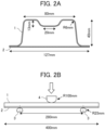
- a hat member 1 is described with reference to FIG. 2A .
- FIG. 2A is a cross-sectional view showing the hat member 1.
- the hat member 1 is joined to a flat plate 2 by spot welding (nugget diameter: 4.5 ⁇ t, spot-to-spot pitch: 35 mm).
- the flat plate 2 is a cold-rolled steel sheet having no plating layer, and has a tensile strength (TS) of 590 MPa and a thickness t that is the same as that of the hat member 1 (1.2 mm).
- TS tensile strength
- FIG. 2B is a schematic view showing the hat member 1 subjected to the three-point bending test. Various dimensions are shown also in FIG. 2B .
- the flat plate 2 joined to the hat member 1 is supported by a support member 3 which is a rigid body.
- an impactor 4 which is a rigid body, is moved from above toward the hat member 1 at a velocity of 1 m/s. In this way, the three-point bending test is performed.
- the three-point bending test was performed three times, and the average value of the maximum loads obtained in those times was defined as the maximum load of the steel sheet.
- the collision proof stress can be rated as excellent.
- Each of the obtained steel sheets was bent using a 90 degree V-block under the test conditions below to obtain a specimen.
- a ridge portion at the apex of the bend in the obtained specimen was observed with a digital microscope (RH-2000, manufactured by HIROX Co., Ltd.) at a magnification of 40X to measure the length of a crack.
- RH-2000 manufactured by HIROX Co., Ltd.
- the crack stopping property can be rated as excellent.
- the steel sheets of Nos. 1 to 3, 5, 6, 10, 15 to 17, 22, 30, and 33 to 42 all had yield strengths of not less than 800 MPa and were excellent in the workability, the collision proof stress, and the crack stopping property.
- the steel sheets of Nos. 4, 7 to 9, 11 to 14, 18 to 21, 23 to 29, 31 and 32 were insufficient in at least one of the yield strength, the workability, the collision proof stress, and the crack stopping property.
Landscapes
- Chemical & Material Sciences (AREA)
- Engineering & Computer Science (AREA)
- Materials Engineering (AREA)
- Metallurgy (AREA)
- Organic Chemistry (AREA)
- Mechanical Engineering (AREA)
- Thermal Sciences (AREA)
- Physics & Mathematics (AREA)
- Crystallography & Structural Chemistry (AREA)
- Chemical Kinetics & Catalysis (AREA)
- Electrochemistry (AREA)
- Oil, Petroleum & Natural Gas (AREA)
- Heat Treatment Of Sheet Steel (AREA)
Abstract
Description
- The invention relates to a high strength steel sheet having a yield strength (YS) of not less than 800 MPa and a method of producing the same as well as a member and a method of producing the same.
- In recent years, in the automotive industry for example, an improvement in the fuel efficiency of automobiles has been hoped for to reduce the carbon dioxide gas (CO2) emission from a viewpoint of the preservation of the global environment.
- In order to improve the fuel efficiency of automobiles, it is effective to reduce the vehicle body weight, and in this case, it is necessary to reduce the vehicle body weight while maintaining the strength of the vehicle body. If the number of automotive parts can be reduced by strengthening a steel sheet which becomes the parts and simplifying the structure of the vehicle body, reduction of the vehicle body weight can be achieved.
- For example,
Patent Literatures 1 to 3 each disclose a high strength steel sheet having a yield strength of not less than 800 MPa. -
- Patent Literature 1:
JP 2018-21231 A - Patent Literature 2:
JP 2018-21233 A - Patent Literature 3:
JP 2017-214647 A - To form a high strength steel sheet having a yield strength of not less than 800 MPa into automotive parts, good workability is required.
- Further, a steel sheet used as automotive parts is also required to be excellent in terms of proof stress at a collision (hereinafter, referred to as "collision proof stress") and to suppress the growth of a crack generated due to an external force at a collision (i.e., to have an excellent crack stopping property).
- Therefore, the present invention aims at providing a high strength steel sheet having a yield strength of not less than 800 MPa and also having excellent workability, collision proof stress, and crack stopping property.
- The present inventors found that employing the configuration described below enables the achievement of the above-mentioned object. The invention has been thus completed.
- Specifically, the present invention provides the following [1] to [10].
- [1] A high strength steel sheet comprising a steel sheet,
- wherein an amount of diffusible hydrogen in steel of the steel sheet is not more than 0.50 mass ppm,
- the steel sheet has chemical composition and microstructure,
- the chemical composition including, by mass,
- C in an amount of 0.150 to 0.500%,
- Si in an amount of 0.01 to 3.00%,
- Mn in an amount of 1.50 to 4.00%,
- P in an amount of not more than 0.100%,
- S in an amount of not more than 0.0200%,
- Al in an amount of not more than 0.100%,
- N in an amount of not more than 0.0100%, and
- O in an amount of not more than 0.0100%, with a balance being Fe and inevitable impurities,
- in the microstructure,
- a total area fraction of tempered martensite and bainite is 55 to 95%,
- a presence ratio A/B of a structure A to a structure B is 0.8 to 2.5, the structure A having a nanohardness of 7 GPa or more, and the structure B having a nanohardness of 6 GPa or less, and
- a concentration of solid solution carbon in retained austenite is 0.50 to 0.90 mass%.
- [2] The high strength steel sheet according to [1] above,
- wherein the chemical composition further includes at least one element selected from the group consisting of, by mass,
- B in an amount of not more than 0.0100%,
- Ti in an amount of not more than 0.200%,
- Nb in an amount of not more than 0.200%,
- V in an amount of not more than 0.200%,
- W in an amount of not more than 0.100%,
- Mo in an amount of not more than 1.000%,
- Cr in an amount of not more than 1.000%,
- Sb in an amount of not more than 0.200%,
- Sn in an amount of not more than 0.200%,
- Zr in an amount of not more than 0.1000%,
- Te in an amount of not more than 0.100%,
- Cu in an amount of not more than 1.000%,
- Ni in an amount of not more than 1.000%,
- Ca in an amount of not more than 0.0100%,
- Mg in an amount of not more than 0.0100%,
- REM in an amount of not more than 0.0100%,
- Co in an amount of not more than 0.010%,
- Ta in an amount of not more than 0.10%,
- Hf in an amount of not more than 0.10%, and
- Bi: in an amount of not more than 0.200%.
- [3] The high strength steel sheet according to [1] or [2] above,
wherein a plating layer is further provided on a surface of a steel sheet. - [4] The high strength steel sheet according to [3] above,
wherein the plating layer is a galvanizing layer, a galvannealing layer, or an electrogalvanizing layer. - [5] A method of producing the high strength steel sheet according to [1] above, the method comprising:
- subjecting a steel slab having the chemical composition according to [1] above to hot rolling to obtain a hot rolled steel sheet;
- subjecting the hot rolled steel sheet to cold rolling to obtain a cold rolled steel sheet; and
- heating the cold rolled steel sheet at a heating temperature T1 of 750°C to 950°C for 10 s to 500 s, cooling the heated cold rolled steel sheet to a cooling stop temperature T2 of not lower than 120°C and lower than 280°C, re-heating the cooled cold rolled steel sheet to a re-heating temperature T3, re-cooling the re-heated cold rolled steel sheet without retaining the re-heated cold rolled steel sheet at the re-heating temperature T3, and retaining the re-cooled cold rolled steel sheet at a temperature T4 lower than the re-heating temperature T3 for 1 s or more,
- wherein a heat-input effect index J from the cooling stop temperature T2 to the re-heating temperature T3, as expressed by Formula (1) below, is 1500 to 4000, and
- the cold rolled steel sheet retained at the temperature T4 is subjected to temper rolling using a roll having a surface roughness of 1.5 to 5.0 µm,

- in Formula (1), t is a heating time from the cooling stop temperature T2 to the re-heating temperature T3 °C, and a unit of the heating time is s.
- [6] A method of producing the high strength steel sheet according to [2] above, the method comprising:
- subjecting a steel slab having the chemical composition according to [2] above to hot rolling to obtain a hot rolled steel sheet;
- subjecting the hot rolled steel sheet to cold rolling to obtain a cold rolled steel sheet; and
- heating the cold rolled steel sheet at a heating temperature T1 of 750°C to 950°C for 10 s to 500 s, cooling the heated cold rolled steel sheet to a cooling stop temperature T2 of not lower than 120°C and lower than 280°C, re-heating the cooled cold rolled steel sheet to a re-heating temperature T3, re-cooling the re-heated cold rolled steel sheet without retaining the re-heated cold rolled steel sheet at the re-heating temperature T3, and retaining the re-cooled cold rolled steel sheet at a temperature T4 lower than the re-heating temperature T3 for 1 s or more,
- wherein a heat-input effect index J from the cooling stop temperature T2 to the re-heating temperature T3, as expressed by Formula (1) below, is 1500 to 4000, and
- the cold rolled steel sheet retained at the temperature T4 is subjected to temper rolling using a roll having a surface roughness of 1.5 to 5.0 µm,

- in Formula (1), t is a heating time from the cooling stop temperature T2 to the re-heating temperature T3 °C, and a unit of the heating time is s.
- [7] The method of producing the high strength steel sheet according to [5] or [6] above,
wherein the cold rolled steel sheet is subjected to a plating treatment. - [8] The method of producing the high strength steel sheet according to [7] above,
wherein the plating treatment is a galvanizing treatment, a galvannealing treatment, or an electrogalvanizing treatment. - [9] A member obtained by using the high strength steel sheet according to any one of [1] to [4] above.
- [10] A method of producing a member, the method comprising subjecting the high strength steel sheet according to any one of [1] to [4] above to at least one of a forming process and a joining process to obtain a member.
- The present invention can provide a high strength steel sheet having a yield strength of not less than 800 MPa and also having excellent workability, collision proof stress, and crack stopping property.
-
- [
FIG. 1] FIG. 1 is a chart diagram showing one example of a heat treatment. - [
FIG. 2A] FIG. 2A is a cross-sectional view showing a hat member. - [
FIG. 2B] FIG. 2B is a schematic view showing the hat member subjected to a three-point bending test. - A high strength steel sheet of the present embodiment (hereinafter also referred to as the "present high strength steel sheet") includes a steel sheet, and may further include a plating layer on a surface of the steel sheet as described later.
- The steel sheet included in the present high strength steel sheet has the chemical composition and microstructure which are to be described later, and satisfies the amount of diffusible hydrogen in steel to be described later.
- The term "high strength" means having a yield strength (YS) of not less than 800 MPa.
- The present high strength steel sheet has a yield strength of not less than 800 MPa and also has excellent workability, collision proof stress, and crack stopping property. Therefore, since the strength against a collision is sufficient, the present high strength steel sheet is suitably used as parts of transportation machines such as automobiles.
- As a method of forming the present high strength steel sheet, a general processing method such as press working can be used without limitation. As a method of welding the present high strength steel sheet, a general welding method such as spot welding or arc welding can be used without limitation.
- First, the steel sheet included in the present high strength steel sheet is described.
- The thickness of the steel sheet is not particularly limited and is, for example, not less than 0.5 mm and not more than 3.0 mm.
- Chemical composition of the steel sheet included in the present high strength steel sheet (hereinafter, conveniently referred to as "present chemical composition") is described.
- The percentage "%" used in the present chemical composition means "mass%" unless otherwise noted.
- C generates martensite to raise the strength of the steel sheet. When the amount of C is too small, the total area fraction of tempered martensite and bainite decreases, whereby the collision proof stress and the yield strength deteriorate. Hence, the amount of C is not less than 0.150%, preferably not less than 0.180%, and more preferably not less than 0.200%.
- Meanwhile, an excessively large amount of C leads to an increase in a structure A having a nanohardness of 7 GPa or more which becomes a starting point of cracking, resulting in lower workability. Hence, the amount of C is not more than 0.500%, preferably not more than 0.460%, and more preferably not more than 0.400%.
- Si suppresses generation of carbides during a heat treatment and influences the hardness of a structure and the concentration of solid solution carbon in retained austenite. From the viewpoint of ensuring a structure having suitable nanohardness and obtaining at least a certain concentration of solid solution carbon in retained austenite, the amount of Si is not less than 0.01%, preferably not less than 0.50%, and more preferably not less than 0.80%.
- Meanwhile, when the amount of Si is too large, the concentration of solid solution carbon in retained austenite excessively increases. Hence, the amount of Si is not more than 3.00%, preferably not more than 2.60%, and more preferably not more than 2.40%.
- Mn influences the area fraction of tempered martensite and bainite. From the viewpoint of obtaining a good collision proof stress and a yield strength of not less than 800 MPa, the amount of Mn is not less than 1.50%, preferably not less than 1.90%, and more preferably not less than 2.30%.
- Meanwhile, an excessively large amount of Mn leads to an increase in the structure A having a nanohardness of 7 GPa or more which becomes a starting point of cracking, resulting in lower workability. Hence, the amount of Mn is not more than 4.00%, preferably not more than 3.50%, and more preferably not more than 3.30%.
- P is segregated in a prior austenite grain boundary to embrittle the grain boundary. This reduces the ultimate deformability of the steel sheet, resulting in lower workability. Accordingly, the amount of P is not more than 0.100%, preferably not more than 0.030%, and more preferably not more than 0.010%.
- While the lower limit of the amount of P is not particularly limited, since P is a solid-solution strengthening element and increases the strength of the steel sheet, the amount of P is preferably 0.001%, more preferably 0.002%, and further preferably 0.003%.
- S combines with Mn to form coarse MnS which becomes a starting point of cracking, resulting in lower workability. Hence, the amount of S is not more than 0.0200%, preferably not more than 0.0100%, and more preferably not more than 0.0020%.
- The lower limit of the amount of S is not particularly limited and is preferably 0.0001%, more preferably 0.0002%, and further preferably 0.0003% due to production engineering restrictions.
- Al increases an A3 transformation point. This leads to an increase in ferrite, and thus the total area fraction of tempered martensite and bainite decreases. Hence, the amount of Al is not more than 0.100%, preferably not more than 0.080%, and more preferably not more than 0.060%.
- The lower limit of the amount of Al is not particularly limited and is, for example, 0.010% and preferably 0.020% because generation of carbides during a heat treatment is suppressed and generation of retained austenite is promoted.
- N combines with Ti to form TiN which becomes a starting point of cracking, resulting in lower workability. Hence, the amount of N is not more than 0.0100%, preferably not more than 0.0080%, and more preferably not more than 0.0060%.
- The lower limit of the amount of N is not particularly limited and is preferably 0.0001%, more preferably 0.0003%, and further preferably 0.0005% due to production engineering restrictions.
- O forms an oxide which becomes a starting point of cracking, resulting in lower workability. Hence, the amount of O is not more than 0.0100%, preferably not more than 0.0050%, and more preferably not more than 0.0020%.
- The present chemical composition may further include at least one element selected from the group consisting of elements described below, in percentage by mass.
- B is preferably added because it is an element capable of improving the hardenability of the steel sheet by being segregated in an austenite grain boundary and increases the yield strength of the steel sheet.
- Meanwhile, when the amount of B is too large, Fe23(CB)6 is formed and becomes a starting point of cracking, resulting in lower workability. Hence, the amount of B is preferably not more than 0.0100%, more preferably not more than 0.0050%, further preferably not more than 0.0040%, and particularly preferably not more than 0.0030%.
- The lower limit of the amount of B is not particularly limited and is, for example, 0.0005% and preferably 0.0010% from the viewpoint of obtaining the effect of addition of B.
- Ti is preferably added because it forms a fine carbide, nitride, or carbonitride during hot rolling or a heat treatment to thereby increase the yield strength of the steel sheet.
- However, when the amount of Ti is too large, Ti combines with N, so that thus-formed coarse nitrides which become starting points of cracking increase, resulting in lower workability. Hence, the amount of Ti is preferably not more than 0.200%, more preferably not more than 0.100%, and further preferably not more than 0.050%.
- The lower limit of the amount of Ti is not particularly limited and is, for example, 0.005%, and preferably 0.010% from the viewpoint of obtaining the effect of addition of Ti.
- Nb, V, and W are preferably added because they form fine carbides, nitrides, or carbonitrides during hot rolling or a heat treatment to thereby increase the yield strength of the steel sheet.
- However, when the amounts to add are excessively large, these elements do not dissolve during steel slab heating and remain as coarse carbides. The coarse carbides become starting points of cracking at a collision, resulting in lower workability. Hence, the amount of Nb is preferably not more than 0.200%, more preferably not more than 0.100%, and further preferably not more than 0.050%. The lower limit thereof is not particularly limited and is, for example, 0.005% and is preferably 0.010% from the viewpoint of obtaining the effect of addition of Nb.
- The amount of V is preferably not more than 0.200%, more preferably not more than 0.100%, and further preferably not more than 0.050%. The lower limit thereof is not particularly limited and is, for example, 0.005% and preferably 0.010% from the viewpoint of obtaining the effect of addition of V.
- The amount of W is preferably not more than 0.100%, more preferably not more than 0.080%, and further preferably not more than 0.050%. The lower limit thereof is not particularly limited and is, for example, 0.010% and preferably 0.020% from the viewpoint of obtaining the effect of addition of W.
- Mo and Cr are preferably added because they increase the hardenability of the steel sheet to thereby increase the yield strength of the steel sheet. However, when the amounts of these elements are excessively large, hard martensite is excessively generated so that a starting point of cracking increases, resulting in lower workability.
- Hence, the amount of Mo is preferably not more than 1.000%, more preferably not more than 0.800%, and further preferably not more than 0.500%. The lower limit thereof is not particularly limited and is, for example, 0.010% and preferably 0.020% from the viewpoint of obtaining the effect of addition of Mo.
- The amount of Cr is preferably not more than 1.000%, more preferably not more than 0.800%, and further preferably not more than 0.500%. The lower limit thereof is not particularly limited and is, for example, 0.010% and preferably 0.020% from the viewpoint of obtaining the effect of addition of Cr.
- Sb and Sn are preferably added because they suppress decarburization of the surfaces of the steel sheet to thereby increase the yield strength of the steel sheet. However, when the amounts of these elements are excessively large, the steel is embrittled, resulting in lower workability.
- Hence, the amount of Sb is preferably not more than 0.200%, more preferably not more than 0.080%, and further preferably not more than 0.040%. The lower limit thereof is not particularly limited and is, for example, 0.001% and preferably 0.002% from the viewpoint of obtaining the effect of addition of Sb.
- The amount of Sn is preferably not more than 0.200%, more preferably not more than 0.080%, and further preferably not more than 0.040%. The lower limit thereof is not particularly limited and is, for example, 0.001% and preferably 0.002% from the viewpoint of obtaining the effect of addition of Sn.
- Zr and Te are preferably added because they spheroidize the shapes of nitrides and sulfides to thereby improve workability. However, when the amounts of these elements are excessively large, coarse precipitates remaining in an undissolved state increase during steel slab heating in hot rolling, thus degrading workability.
- Hence, the amount of Zr is preferably not more than 0.1000%, more preferably not more than 0.0800%, and further preferably not more than 0.0500%. The lower limit thereof is not particularly limited and is, for example, 0.0050% and preferably 0.0100% from the viewpoint of obtaining the effect of addition of Zr.
- The amount of Te is preferably not more than 0.100%, more preferably not more than 0.080%, and further preferably not more than 0.050%. The lower limit thereof is not particularly limited and is, for example, 0.005% and preferably 0.010% from the viewpoint of obtaining the effect of addition of Te.
- Cu is preferably added because it increases the hardenability of the steel sheet to thereby increase the yield strength of the steel sheet. However, when the amount of Cu is excessively large, inclusions of Cu increase, thus degrading workability.
- Hence, the amount of Cu is preferably not more than 1.000%, more preferably not more than 0.800%, and further preferably not more than 0.500%. The lower limit thereof is not particularly limited and is, for example, 0.010% and preferably 0.020% from the viewpoint of obtaining the effect of addition of Cu.
- Ni is preferably added because it increases the hardenability of the steel sheet to thereby increase the yield strength of the steel sheet. However, when the amount of Ni is excessively large, hard martensite increases, thus degrading workability.
- Hence, the amount of Ni is preferably not more than 1.000%, more preferably not more than 0.800%, and further preferably not more than 0.500%. The lower limit thereof is not particularly limited and is, for example, 0.010% and preferably 0.020% from the viewpoint of obtaining the effect of addition of Ni.
- Ca, Mg, and REM (Rare Earth Metal) are preferably added because they spheroidize the shapes of precipitates such as sulfides and oxides, thus improving workability. However, when the amounts of these elements are excessively large, coarse sulfides become starting points of cracking at a collision, thus degrading workability.
- Hence, the amount of Ca is preferably not more than 0.0100%, more preferably not more than 0.0050%, and further preferably not more than 0.0040%. The lower limit thereof is not particularly limited and is, for example, 0.0005% and preferably 0.0010% from the viewpoint of obtaining the effect of addition of Ca.
- The amount of Mg is preferably not more than 0.0100%, more preferably not more than 0.0050%, and further preferably not more than 0.0040%. The lower limit thereof is not particularly limited and is, for example, 0.0005% and preferably 0.0010% from the viewpoint of obtaining the effect of addition of Mg.
- The amount of REM is preferably not more than 0.0100%, more preferably not more than 0.0040%, and further preferably not more than 0.0030%. The lower limit thereof is not particularly limited and is, for example, 0.0005% and preferably 0.0010% from the viewpoint of obtaining the effect of addition of REM.
- Co, Ta, Hf, and Bi are preferably added because they spheroidize the shapes of precipitates to thereby improve workability. However, when the amounts of these elements are excessively large, coarse precipitates become starting points of cracking, thus degrading workability.
- Hence, the amount of Co is preferably not more than 0.010%, more preferably not more than 0.008%, and further preferably not more than 0.007%. The lower limit thereof is not particularly limited and is, for example, 0.001% and preferably 0.002% from the viewpoint of obtaining the effect of addition of Co.
- The amount of Ta is preferably not more than 0.10%, more preferably not more than 0.08%, and further preferably not more than 0.07%. The lower limit thereof is not particularly limited and is, for example, 0.01% and preferably 0.02% from the viewpoint of obtaining the effect of addition of Ta.
- The amount of Hf is preferably not more than 0.10%, more preferably not more than 0.08%, and further preferably not more than 0.07%. The lower limit thereof is not particularly limited and is, for example, 0.01% and preferably 0.02% from the viewpoint of obtaining the effect of addition of Hf.
- The amount of Bi is preferably not more than 0.200%, more preferably not more than 0.100%, and further preferably not more than 0.080%. The lower limit thereof is not particularly limited and is, for example, 0.001% and preferably 0.005% from the viewpoint of obtaining the effect of addition of REM.
- The balance in the present chemical composition consists of Fe and inevitable impurities.
- Next, the microstructure of the steel sheet included in the present high strength steel sheet (hereinafter, conveniently referred to as "present microstructure") is described.
- In order to obtain the effect of the present invention, it is not enough to satisfy the present chemical composition alone, and it is necessary to satisfy the present microstructure described below.
- Hereinbelow, the area fraction is an area fraction with respect to the entire microstructure. The area fraction of each structure is determined by a method described in Examples below.
- From the viewpoint of stably securing good collision proof stress and yield strength, the total area fraction of tempered martensite and bainite is not less than 55%, preferably not less than 58%, and more preferably not less than 60%.
- Meanwhile, when the total area fraction of tempered martensite and bainite is too large, the structure A having a nanohardness of 7 GPa or more increases, and a presence ratio of the structure A to a structure B (A/B) becomes excessively high, thus degrading workability.
- Accordingly, this total area fraction is not more than 95%, preferably not more than 92%, and more preferably not more than 88%.
- The structure A having a nanohardness of 7 GPa or more is fine and hard, and hence stops the growth of a crack generated due to an external force at a collision, thus improving a crack stopping property.
- The structure B having a nanohardness of 6 GPa or less has high toughness and thus improves workability.
- When the presence ratio of the structure A to the structure B (A/B) is appropriately controlled, the crack stopping property and the workability are both excellent.
- The presence ratio (A/B) is not less than 0.8, preferably not less than 1.0, and more preferably not less than 1.1 for the reason that the crack stopping property is excellent.
- Meanwhile, when the presence ratio of the structure A to the structure B (A/B) is too high, the structure A having a nanohardness of 7 GPa or more becomes a starting point of cracking, thus degrading workability. Hence, the presence ratio (A/B) is not more than 2.5, preferably not more than 2.3, and more preferably not more than 2.0.
- The nanohardness is the hardness measured using a nanoindentation method and specifically is determined by a method described in Examples to be described later.
- A plastic deformation resistance in a local region of a structure at a submicron level cannot be evaluated by use of other hardnesses (for instance, Vickers hardness) than the nanohardness.
- The present microstructure contains retained austenite.
- When the concentration of solid solution carbon in retained austenite is too high and when a stress is repeatedly applied, the hardness of martensite transformed from the retained austenite greatly increases, and this results in an increase in starting points of cracking, thus degrading workability.
- Hence, the concentration of solid solution carbon in retained austenite is not more than 0.90 mass%, preferably not more than 0.85 mass%, and more preferably 0.80 mass%.
- Meanwhile, when the concentration of solid solution carbon in retained austenite is too low, the workability decreases.
- Hence, the concentration of solid solution carbon in retained austenite is not less than 0.50 mass%, preferably not less than 0.60 mass%, and more preferably not less than 0.70 mass%.
- The present microstructure may include a structure (remaining structure) other than tempered martensite, bainite and retained austenite.
- Examples of the remaining structure include known structures such as fresh martensite; pearlite; ferrite; iron-based carbonitride; alloyed carbonitride; and inclusions such as MnS and Al2O3.
- The area fraction of the remaining structure is preferably not more than 20%, more preferably not more than 10%, and further preferably not more than 5%. When the area fraction of the remaining structure falls within this range, the effect of the present invention would not be impaired.
- When the amount of diffusible hydrogen in steel is too large, delayed fracture occurs, thus degrading workability. Hence, the amount of diffusible hydrogen in steel is not more than 0.50 mass ppm, preferably not more than 0.30 mass ppm, and more preferably not more than 0.20 mass ppm.
- The amount of diffusible hydrogen in steel is determined by a method described in Examples to be described later.
- The present high strength steel sheet may further have a plating layer on a surface of the steel sheet for the purpose of improving corrosion resistance and other properties.
- Examples of the plating layer include a galvanizing layer, a galvannealing layer and an electrogalvanizing layer. The plating layer is formed by a plating treatment to be described later.
- Next, a method of producing a high strength steel sheet according to the present embodiment (hereinafter also referred to as "present production method") is described. The present production method is a method of producing the present high strength steel sheet described above.
- The temperature at which a steel slab, the steel sheet, or the like is heated or cooled, which is described below, means a surface temperature of the steel slab, the steel sheet, or the like, unless otherwise specified.
- A method of producing molten steel which becomes a steel slab (steel material) is not particularly limited, and known methods using a converter, an electric furnace, or the like are applicable. It is preferable to obtain a steel slab from molten steel by a continuous casting method. Another method such as an ingot casting blooming method or a thin slab continuous casting method may be adopted to obtain a steel slab.
- In the present production method, first, a steel slab having the present chemical composition described above is hot-rolled. Thus, a hot rolled steel sheet is obtained.
- When the hot rolling is performed, the steel slab may be re-heated in a heating furnace and then rolled. When the steel slab maintains a temperature equal to or higher than a predetermined temperature, the steel slab may be directly rolled without being heated.
- In the hot rolling, the steel slab is subjected to rough rolling and finish rolling.
- Preferably, the steel slab is heated to dissolve carbides in the steel slab prior to the rough rolling.
- From the viewpoint of dissolving carbides or preventing an increase in rolling load, the temperature at the time of heating the steel slab (steel slab heating temperature) is preferably not lower than 1100°C and more preferably not lower than 1150°C.
- On the other hand, from the viewpoint of preventing an increase in scale loss, the steel slab heating temperature is preferably not higher than 1300°C and more preferably not higher than 1280°C.
- As described above, when the steel slab before the rough rolling maintains a temperature equal to or higher than a predetermined temperature and carbides in the steel slab are dissolved, heating of the steel slab before the rough rolling can be omitted.
- The conditions of the rough rolling and the finish rolling are not particularly limited, and for example, a finish rolling end temperature is preferably 700°C to 1100°C, and more preferably 800°C to 1000°C.
- Next, the hot rolled steel sheet is subjected to cold rolling to obtain a cold rolled steel sheet.
- A rolling rate of the cold rolling is preferably not less than 30% and more preferably not less than 35%. The upper limit thereof is not particularly limited and is, for example, not more than 70% and preferably not more than 65%.
- Next, the cold rolled steel sheet obtained by the cold rolling is subjected to a heat treatment.
-
FIG. 1 is a chart diagram showing an example of the heat treatment. - In the heat treatment, in short, the cold rolled steel sheet is heated at a heating temperature T1, cooled to a cooling stop temperature T2, then re-heated to a re-heating temperature T3, and re-cooled without being retained at the re-heating temperature T3. In the re-cooling, the cold rolled steel sheet is retained at a temperature T4 lower than the re-heating temperature T3.
- The cold rolled steel sheet having undergone the heat treatment and then temper rolling, which will be described later, corresponds to the steel sheet included in the present high strength steel sheet described above.
- First, the cold rolled steel sheet is heated at the heating temperature T1.
- At this time, when the heating temperature T1 is too low or when a heating time t1 (the time for retaining the cold rolled steel sheet at the heating temperature T1) is too short, the steel sheet is heated in a dual phase region of ferrite and austenite. In this case, the final microstructure contains ferrite, so that the total area fraction of tempered martensite and bainite decreases.
- Hence, the heating temperature T1 is not lower than 750°C, preferably not lower than 800°C, and more preferably not lower than 850°C. The heating time t1 is not less than 10 s, preferably not less than 50 s, and more preferably not less than 80 s.
- Meanwhile, when the heating temperature T1 is too high or when the heating time t1 is too long, the amount of hydrogen entering steel increases due to an increase in hydrogen partial pressure, whereby the amount of diffusible hydrogen in steel increases.
- In addition, the total area fraction of tempered martensite and bainite increases, and this leads to an excessively high presence ratio (A/B), thus degrading workability.
- Hence, the heating temperature T1 is not higher than 950°C, preferably not higher than 930°C, and more preferably not higher than 900°C. The heating time t1 is not more than 500 s, preferably not more than 300 s, and more preferably not more than 200 s.
- Next, the cold rolled steel sheet having been heated at the heating temperature T1 is cooled to the cooling stop temperature T2.
- When the cooling stop temperature T2 is too low, the total area fraction of tempered martensite and bainite increases, and this leads to an excessively high presence ratio (A/B), thus degrading workability.
- Hence, the cooling stop temperature T2 is not lower than 120°C, preferably not lower than 140°C, and more preferably not lower than 150°C.
- Meanwhile, when the cooling stop temperature T2 is too high, the total area fraction of tempered martensite and bainite decreases. In addition, the structure B having a nanohardness of 6 GPa or less increases, and this leads to an excessively low presence ratio (A/B), resulting in a poorer crack stopping property.
- Hence, the cooling stop temperature T2 is less than 280°C, preferably not higher than 270°C, and more preferably not higher than 260°C.
- Next, the cold rolled steel sheet having been cooled to the cooling stop temperature T2 is re-heated to the re-heating temperature T3 and is re-cooled without being retained at the re-heating temperature T3.
- The re-heating temperature T3 is not particularly limited as long as it satisfies a heat-input effect index J to be described later.
- The re-heating temperature T3 is for instance not lower than 280°C, preferably not lower than 290°C, and more preferably not lower than 300°C.
- On the other hand, the re-heating temperature T3 is for instance not higher than 400°C, preferably not higher than 380°C, and more preferably not higher than 350°C.
- The heat-input effect index J from the cooling stop temperature T2 to the re-heating temperature T3 with respect to the cold rolled steel sheet is expressed by Formula (1):

- In Formula (1) above, t is a heating time (unit: s) from the cooling stop temperature T2 to the re-heating temperature T3 °C.
- The nanohardnesses of the structures composing the microstructure change depending on the state of presence of carbon in those structures. The heat-input effect index J influences not only the state of presence of carbon but also the speed of diffusion of carbon and the place where carbon is present.
- When the heat-input effect index J is too low, carbon in a structure is present in a solid solution state; consequently, the structure A having a nanohardness of 7 GPa or more increases, and this leads to an excessively high presence ratio (A/B), thus degrading workability. In addition, the concentration of solid solution carbon in retained austenite becomes excessively high, thus degrading workability.
- Hence, the heat-input effect index J is not lower than 1500, preferably not lower than 1800, and more preferably not lower than 2000.
- Meanwhile, when the heat-input effect index J is too high, carbon in a structure is present as a carbide; consequently, the structure B having a nanohardness of 6 GPa or less increases, and this leads to an excessively low presence ratio (A/B), resulting in a poorer crack stopping property. In addition, the concentration of solid solution carbon in retained austenite becomes excessively low, thus degrading workability.
- Hence, the heat-input effect index J is not more than 4000, preferably not more than 3800, and more preferably not more than 3500.
- In the re-cooling, the cold rolled steel sheet is retained at the temperature T4 lower than the re-heating temperature T3.
- The temperature T4 being not lower than the re-heating temperature T3 leads to an excessively low presence ratio (A/B), resulting in a poorer crack stopping property.
- The lower limit of the temperature T4 is not particularly limited and is for instance 180°C, preferably 200°C, and more preferably 220°C.
- When the cold rolled steel sheet is not retained at the temperature T4 (for example, when the retaining time t4 at the temperature T4 is zero), the presence ratio (A/B) becomes excessively high, thus degrading workability.
- Hence, the retaining time t4 is 1 s or more, preferably 3 s or more, and more preferably 5 s or more.
- Next, the cold rolled steel sheet having undergone the heat treatment (specifically, having been retained at the temperature T4 for 1 s or more) is subjected to temper rolling using a roll.
- The surface roughness of a roll is controlled to adjust movable dislocation introduced in a local region at a submicron level, thus controlling the hardness distribution of a structure.
- When the surface roughness of a roll is too small, the presence ratio (A/B) becomes too low, resulting in a poorer crack stopping property. Hence, the surface roughness of a roll is not less than 1.5 µm, preferably not less than 1.8 µm, and more preferably not less than 2.0 µm.
- Meanwhile, when the surface roughness of a roll is too large, the presence ratio (A/B) becomes too high, thus degrading workability. Hence, the surface roughness of a roll is not more than 5.0 µm, preferably not more than 4.5 µm, and more preferably not more than 4.0 µm.
- The surface roughness of a roll is an arithmetic average roughness Ra measured according to JIS B 0601.
- In the present production method, the cold rolled steel sheet having undergone the temper rolling may be subjected to a plating treatment to form a plating layer on the surface thereof.
- Examples of the plating layer include a galvanizing layer, a galvannealing layer, and an electrogalvanizing layer.
- For the plating treatment, galvanizing treatment, galvannealing treatment, or electrogalvanizing treatment is preferred.
- When the galvanizing treatment is performed, for example, the steel sheet is immersed in a zinc bath having a bath temperature of 440°C to 500°C to be galvanized. Thereafter, it is preferable to adjust a coating weight of the plating layer by gas wiping or other methods.
- As the zinc bath, a zinc bath having a chemical composition including the Al content of 0.10 to 0.23 mass% with the balance being Zn and inevitable impurities is preferred.
- When the galvannealing treatment is performed, an excessively low alloying temperature causes an excessively low Zn-Fe alloying rate, and this may make alloying extremely difficult. On the other hand, when the alloying temperature is too high, untransformed austenite may be transformed into pearlite. Hence, the alloying temperature is preferably 450°C to 600°C, more preferably 470°C to 550°C, and further preferably 470°C to 530°C.
- The electrogalvanizing treatment is performed to form an electrogalvanizing layer.
- The type of the electrogalvanizing layer is not particularly limited, and known electrogalvanizing layers are advantageously applicable. The electrogalvanizing layer may be a zinc alloy plating layer obtained by adding, to Zn, one or more of such elements as Fe, Cr, Ni, Mn, Co, Sn, Pb, and Mo in suitable amounts in accordance with the intended purpose.
- The coating weight of the plating layer of a galvanized steel sheet (GI), a galvannealed steel sheet (GA), or an electrogalvanized steel sheet (EG) is preferably 20 to 80 g/m2 per one side (double-sided plating) .
- The steel sheet having undergone the plating treatment is cooled to a temperature of, for example, not higher than 50°C. The steel sheet having been cooled to a temperature of not higher than 50°C may be subjected to rolling at an elongation rate of 0.05% to 1.00%. The elongation rate is preferably 0.08% to 0.70%.
- The rolling may be performed in an apparatus that is continuous with an apparatus (plating apparatus) performing the galvanizing treatment, or may be performed in an apparatus that is discontinuous with the plating apparatus. In addition, a desired elongation rate may be achieved by one rolling operation, or a plurality of rolling operations may be performed to achieve a desired elongation rate in total.
- Meanwhile, the rolling described here generally refers to temper rolling, but it may be rolling performed by processing using a leveler or the like as long as it is possible to impart an elongation rate equivalent to that achieved by temper rolling.
- In the present production method, for example, the retaining temperature such as the heating temperature or the re-heating temperature need not be constant as long as it is within the above-described temperature range. A cooling rate may vary during cooling as long as it is within the above-described rate range. The heat treatment may be performed in any equipment as long as the conditions such as the above-described temperature range are satisfied.
- Next, a member of the present embodiment (hereinafter also referred to as "present member") is described.
- The present member is a member formed by using the present high strength steel sheet described above as at least part of the member, and is, for example, a member formed into a target shape by processing (e.g., pressing) the present high strength steel sheet.
- The present member is preferably a member for automotive parts. Note that the member for automotive parts may include a steel sheet other than the present high strength steel sheet as a material.
- As described above, the present high strength steel sheet has a yield strength of not less than 800 MPa and also has excellent workability, collision proof stress, and crack stopping property. Therefore, the present member is excellent in workability, collision proof stress, and crack stopping property and also can contribute to reduction of the vehicle body weight, and thus is suitable for all members used in, among automotive parts, particularly skeletal structure parts or reinforcing parts of automobiles.
- Next described is a method for producing the present member.
- The present member is obtained by, for example, subjecting the present high strength steel sheet to at least one of a forming process and a joining process.
- The forming process is not particularly limited, and examples thereof include press working.
- The joining process is not particularly limited, and examples thereof include: general welding such as spot welding and arc welding; and crimping using rivets; and the like.
- The invention is specifically described below by way of Examples. However, the invention is not limited to the examples described below.
- Molten steel having the chemical composition as shown in Table 1 below with the balance being Fe and inevitable impurities was made in a converter, and a steel slab was obtained by a continuous casting method. In Table 1 below, the underlined figures mean those out of the ranges of the invention (the same applies to Tables 2 to 3 to be described later).
- The steel slabs thus obtained were subjected to hot rolling under the conditions described in Table 2 below, and thus hot rolled steel sheets were obtained. Specifically, each steel slab was heated to 1250°C and rough rolled, followed by finish rolling at a finish rolling end temperature of 900°C.
- The hot rolled steel sheet obtained was subjected to cold rolling at a rolling rate shown in Table 2 below, thereby obtaining a cold rolled steel sheet (thickness: 1.2 mm).
- The cold rolled steel sheet obtained was subjected to a heat treatment under the conditions shown in Table 2 below.
- Further, the cold rolled steel sheet having undergone the heat treatment was subjected to temper rolling under the conditions shown in Table 2 below.
- In some examples, both surfaces of the cold rolled steel sheet (CR) after the temper rolling were subjected to a plating treatment to obtain a galvanized steel sheet (GI), a galvannealed steel sheet (GA), or an electrogalvanized steel sheet (EG).
- As a galvanizing bath, when GI was produced, a zinc bath containing Al: 0.20 mass% with the balance being Zn and inevitable impurities was used, and when GA was produced, a zinc bath containing Al: 0.14 mass% with the balance being Zn and inevitable impurities was used.
- The bath temperature was 470°C for both GI and GA production.
- The coating weight of the plating layer was 45 to 72 g/m2 per one side when GI was produced and 45 g/m2 per one side when GA was produced.
- When GA was produced, the alloying temperature was 500°C.
- The composition of the plating layer of GI was the composition including Fe: 0.1 to 1.0 mass% and Al: 0.2 to 1.0 mass% with the balance being Fe and inevitable impurities. The composition of the plating layer of GA was the composition including Fe: 7 to 15 mass% and Al: 0.1 to 1.0 mass% with the balance being Fe and inevitable impurities.
- When EG was produced, an electrogalvanizing treatment was performed using an electrogalvanizing line such that the resulting plating layer had a coating weight of 30 g/m2 per one side.
- Hereinbelow, each of the cold rolled steel sheet (CR) after the heat treatment, the galvanized steel sheet (GI), the galvannealed steel sheet (GA), and the electrogalvanized steel sheet (EG) is also simply referred to as "steel sheet."
- For each of the steel sheets thus obtained, the microstructure was observed as described below. The results are shown in Table 3 below. In Table 3 below, martensite is denoted as "M," bainite is denoted as "B," and austenite is denoted as "γ."
- The obtained steel sheet was polished such that a cross section (L cross section) at a position of 1/4 of the sheet thickness and parallel to the rolling direction became an observation surface. The observation surface was etched using 1 vol% Nital, and then enlarged and observed with a scanning electron microscope (SEM) at a magnification of 3000X.
- The observation surface was observed in 10 fields, and SEM images were obtained. The obtained SEM images were analyzed to determine the total area fraction (unit: %) of tempered martensite and bainite.
- More specifically, dark gray parts in each obtained SEM image were determined to be tempered martensite and bainite, and the area fraction (average area fraction of the 10 fields) was determined. For the SEM image analysis, Image-Pro available from Media Cybernetics Inc. was used as analysis software.
- The obtained steel sheet was polished such that a cross section (L cross section) at a position of 1/4 of the sheet thickness and parallel to the rolling direction became an observation surface. The observation surface was mirror polished with diamond paste, followed by finishing polishing with colloidal silica.
- The nanohardness of the observation surface was measured at 225 points by use of a nanoindentation device having a Berkovich indenter.
- The measurement conditions are set as: a loading rate and an unloading rate of 50 µN/s; a maximum load of 500 µN; a data collecting pitch of 5 ms; and a distance between dents of 2 µm or more.
- Of the 225 measurement points, measurement points having a nanohardness of 7 GPa or more were specified as the structure A, while measurement points having a nanohardness of 6 GPa or less were specified as the structure B, and the ratio between the numbers of the measurement points was determined as the presence ratio (A/B) of the structure A to the structure B.
- The obtained steel sheet was ground such that a position of 1/4 of the sheet thickness became an observation surface, and further polished 0.1 mm by chemical polishing.
- With respect to the observation surface, peak angles of the (200) surface, (220) surface, and (311) surface of austenite were obtained using an X-ray diffraction (XRD) instrument with CoKα as an X-ray source, and a lattice constant a (unit: Å) of retained austenite was calculated by Formula (2) below.
- The calculated lattice constant a of retained austenite was substituted into Formula (3) below to thereby determine the content (unit: mass%) of carbon (C) in the retained austenite, and the result was defined as the concentration of solid solution carbon in the retained austenite.

a = 3.572 + 0.0012 [Mn] - 0.00157 [Si] + 0.0056 [Al] + 0.033 [C] - In Formula (2), a is a lattice constant (unit: Å) of retained austenite, and θ is a value (unit: rad) obtained by dividing a diffraction peak angle of the (220) surface by 2.
- In Formula (3), a is a lattice constant (unit: Å) of retained austenite, and [M] is the content (unit: mass%) of an element M in the retained austenite. It should be noted, for the content of the element M other than C, the content of each element in the chemical composition (specifically, the present chemical composition described above, for example) of the whole steel sheet is used.
- A specimen having a length of 30 mm and a width of 5 mm was sampled from the obtained steel sheet. For the sampled specimen, the amount of diffusible hydrogen in steel was measured by a thermal desorption analysis method. The heating rate was set to 200°C/hr. The cumulative value of the amount of hydrogen detected in the temperature range from room temperature (25°C) to a temperature lower than 210°C was defined as the amount of diffusible hydrogen in steel (unit: mass ppm).
- The steel sheet on which the plating layer had been formed was measured in the same manner after the plating layer was removed using a router (precision grinder).
- The result is shown in Table 3 below. The amount of diffusible hydrogen in steel is preferably not more than 0.50 mass ppm.
- The obtained steel sheets were evaluated by the following methods. The results are shown in Table 3 below.
- From each of the obtained steel sheets, No. 5 specimen described in JIS Z 2241 with its longitudinal direction (tensile direction) being a direction of 90° to the rolling direction was sampled. Using the specimen thus sampled, a tensile test according to JIS Z 2241 was performed five times, and the yield strength (YS) and the elongation (El) were determined from the average value of the five times.
- When the YS was not less than 800 MPa, the strength can be rated as high.
- When the El was not less than 8.0%, the ductility can be rated as good, and the workability can be rated as excellent.
- Using each of the obtained steel sheets, a member (hat member) having a hat-shaped cross section was produced, and a three-point bending test was performed to determine the maximum load (unit: kN).
- First, a
hat member 1 is described with reference toFIG. 2A . -
FIG. 2A is a cross-sectional view showing thehat member 1. InFIG. 2A , the dimensions of thehat member 1 are shown. Thehat member 1 is joined to aflat plate 2 by spot welding (nugget diameter: 4.5√t, spot-to-spot pitch: 35 mm). Theflat plate 2 is a cold-rolled steel sheet having no plating layer, and has a tensile strength (TS) of 590 MPa and a thickness t that is the same as that of the hat member 1 (1.2 mm). - Next, the three-point bending test is described with reference to
FIG. 2B . -
FIG. 2B is a schematic view showing thehat member 1 subjected to the three-point bending test. Various dimensions are shown also inFIG. 2B . Theflat plate 2 joined to thehat member 1 is supported by asupport member 3 which is a rigid body. In this state, animpactor 4, which is a rigid body, is moved from above toward thehat member 1 at a velocity of 1 m/s. In this way, the three-point bending test is performed. - For each steel sheet, the three-point bending test was performed three times, and the average value of the maximum loads obtained in those times was defined as the maximum load of the steel sheet.
- When the maximum load was not less than 40 kN, "A" was given, when the maximum load was not less than 30 kN and less than 40 kN, "B" was given, and when the maximum load was less than 30 kN, "C" was given in Table 3 below.
- When the result is A or B, the collision proof stress can be rated as excellent.
- Each of the obtained steel sheets was bent using a 90 degree V-block under the test conditions below to obtain a specimen. A ridge portion at the apex of the bend in the obtained specimen was observed with a digital microscope (RH-2000, manufactured by HIROX Co., Ltd.) at a magnification of 40X to measure the length of a crack. When plural cracks are present, the sum of the lengths of the cracks was obtained.
- When the sum of the lengths of cracks was not more than 6000 µm, "A" was given, when the sum of the lengths of cracks was more than 6000 µm and less than 12000 µm, "B" was given, and when the sum of the lengths of cracks was not less than 12000 µm, "C" was given in Table 3 below.
- When the result is A or B, the crack stopping property can be rated as excellent.
-
- Test method: roll supporting, punch pressing
- Roll diameter: φ 30 mm
- Punch tip R: 0.4 mm
- Distance between rolls: (thickness x 2) + 0.5 mm
- Stroke rate: 20 mm/min
- Specimen size: 60 mm x 60 mm
- Bending direction: Rolling perpendicular method
- As shown in Tables 1 to 3 above, the steel sheets of Nos. 1 to 3, 5, 6, 10, 15 to 17, 22, 30, and 33 to 42 all had yield strengths of not less than 800 MPa and were excellent in the workability, the collision proof stress, and the crack stopping property.
- In contrast, the steel sheets of Nos. 4, 7 to 9, 11 to 14, 18 to 21, 23 to 29, 31 and 32 were insufficient in at least one of the yield strength, the workability, the collision proof stress, and the crack stopping property.
| Table 1 (1/2) | |||||||||||||||
| Steel ID | Chemical composition [mass%] | ||||||||||||||
| C | Si | Mn | P | S | Al | N | O | B | Ti | Nb | V | W | Mo | Cr | |
| A | 0.232 | 1.26 | 2.72 | 0.006 | 0.0005 | 0.035 | 0.0040 | 0.0006 | 0.0019 | 0.021 | 0.020 | - | - | - | - |
| B | 0.301 | 1.45 | 3.11 | 0.004 | 0.0008 | 0.036 | 0.0041 | 0.0007 | - | - | 0.019 | - | - | - | - |
| C | 0.251 | 1.31 | 2.76 | 0.005 | 0.0010 | 0.040 | 0.0039 | 0.0006 | - | - | - | 0.088 | - | - | - |
| D | 0.155 | 1.50 | 3.42 | 0.010 | 0.0010 | 0.052 | 0.0042 | 0.0008 | - | - | - | - | 0.025 | - | - |
| E | 0.288 | 2.92 | 1.52 | 0.009 | 0.0015 | 0.045 | 0.0048 | 0.0012 | - | - | 0.047 | - | - | 0.197 | - |
| F | 0.245 | 1.35 | 2.76 | 0.011 | 0.0011 | 0.042 | 0.0051 | 0.0004 | 0.0044 | 0.021 | - | - | - | - | - |
| G | 0.277 | 1.42 | 2.35 | 0.004 | 0.0007 | 0.031 | 0.0061 | 0.0006 | - | - | - | - | - | - | - |
| H | 0.221 | 1.08 | 1.42 | 0.012 | 0.0019 | 0.029 | 0.0035 | 0.0007 | - | - | - | 0.025 | - | - | - |
| I | 0.193 | 1.26 | 4.04 | 0.010 | 0.0020 | 0.041 | 0.0041 | 0.0010 | - | - | 0.035 | - | - | - | - |
| J | 0.503 | 1.25 | 2.23 | 0.006 | 0.0015 | 0.036 | 0.0038 | 0.0020 | - | - | - | - | - | - | - |
| K | 0.143 | 1.15 | 3.10 | 0.007 | 0.0012 | 0.055 | 0.0059 | 0.0042 | - | - | - | - | - | - | - |
| L | 0.261 | 1.65 | 2.55 | 0.013 | 0.0009 | 0.039 | 0.0035 | 0.0006 | - | - | - | - | - | - | 0.220 |
| M | 0.261 | 3.15 | 2.64 | 0.015 | 0.0015 | 0.032 | 0.0051 | 0.0050 | - | - | - | - | - | - | - |
| N | 0.252 | 0.003 | 2.63 | 0.018 | 0.0015 | 0.083 | 0.0034 | 0.0030 | - | - | - | - | - | - | - |
| O | 0.315 | 1.62 | 2.75 | 0.008 | 0.0009 | 0.032 | 0.0041 | 0.0004 | - | - | - | - | - | - | - |
| P | 0.242 | 1.36 | 2.62 | 0.006 | 0.0009 | 0.041 | 0.0038 | 0.0006 | - | - | - | - | - | - | - |
| Q | 0.265 | 1.31 | 2.83 | 0.009 | 0.0009 | 0.054 | 0.0042 | 0.0006 | - | - | - | - | - | - | - |
| R | 0.254 | 1.26 | 2.85 | 0.010 | 0.0009 | 0.042 | 0.0051 | 0.0006 | - | - | - | - | - | - | - |
| S | 0.235 | 1.35 | 2.72 | 0.005 | 0.0009 | 0.053 | 0.0034 | 0.0006 | - | 0.091 | - | - | - | - | - |
| T | 0.189 | 0.04 | 2.87 | 0.015 | 0.0016 | 0.029 | 0.0052 | 0.0015 | - | - | - | - | - | - | - |
| U | 0.225 | 2.75 | 2.65 | 0.016 | 0.0014 | 0.091 | 0.0041 | 0.0016 | - | - | - | - | - | - | - |
| V | 0.311 | 0.44 | 2.65 | 0.012 | 0.0011 | 0.041 | 0.0092 | 0.0004 | - | - | - | - | - | - | - |
| W | 0.238 | 1.26 | 3.55 | 0.010 | 0.0020 | 0.059 | 0.0038 | 0.0006 | - | - | - | - | - | - | - |
| X | 0.238 | 1.32 | 1.83 | 0.015 | 0.0016 | 0.049 | 0.0025 | 0.0004 | - | - | - | - | - | - | - |
| Steel ID | Chemical composition [mass%] | ||||||||||||
| Sb | Sn | Zr | Cu | Ni | Ca | Mg | Co | Ta | REM | Hf | Te | Bi | |
| A | - | - | - | - | - | - | - | - | - | - | - | - | - |
| B | 0.006 | - | - | - | - | - | - | - | - | - | - | - | - |
| C | - | - | - | - | - | - | - | - | - | - | - | - | - |
| D | - | - | - | - | - | - | - | - | - | - | - | - | - |
| E | - | - | - | - | - | - | - | - | - | - | - | - | - |
| F | - | - | - | 0.115 | - | - | - | - | - | - | - | - | - |
| G | - | - | - | - | - | - | - | - | - | - | - | - | - |
| H | - | - | - | - | - | - | - | - | - | - | - | - | - |
| I | - | - | - | - | - | - | - | - | - | - | - | - | - |
| J | - | - | - | - | - | - | - | - | - | - | - | - | - |
| K | - | - | - | - | - | - | - | - | - | - | - | - | - |
| L | 0.015 | - | - | - | - | - | - | - | - | - | - | - | - |
| M | - | - | - | - | - | - | - | - | - | - | - | - | - |
| N | - | - | - | - | - | - | - | - | - | - | - | - | - |
| O | - | 0.010 | 0.0220 | - | - | - | - | - | - | - | - | - | - |
| P | - | - | - | 0.220 | 0.125 | - | - | - | - | - | - | - | - |
| Q | - | - | - | - | - | 0.0012 | 0.0020 | - | - | - | - | - | - |
| R | - | - | - | - | - | - | - | 0.005 | - | - | - | - | - |
| S | - | - | - | - | - | - | - | - | 0.03 | 0.0010 | - | - | - |
| T | - | - | - | - | - | - | - | - | - | - | 0.03 | 0.005 | - |
| U | - | - | - | - | - | - | - | - | - | - | - | - | - |
| V | - | - | - | - | - | - | - | - | - | - | - | - | - |
| W | - | - | - | 0.360 | - | - | - | - | - | - | - | - | 0.013 |
| X | - | - | - | - | - | - | - | - | - | - | - | - | 0.004 |
| Table 2 (1/2) | |||||||||||||||
| No. | Steel ID | Hot rolling | Cold rolling | Heat treatment | Temper rolling | Plating treatment | Remarks | ||||||||
| Steel slab heating temperature [°C] | Finish rolling end temperature [°C] | Rolling rate [%] | Heating temperature T1 [°C] | Heating time t1 [s] | Cooling stop temperature T2 [°C] | Re-heating temperature T3 [°C] | Heating time t from T2 to T3 [s] | Temperature T4 [°C] | Retaining time t4 at T4 [s] | Heat-input effect index J | Roll surface roughness [µ m] | ||||
| 1 | A | 1250 | 900 | 45 | 870 | 150 | 200 | 310 | 7 | 300 | 35 | 2398 | 2.9 | CR | Compatible steel |
| 2 | A | 1250 | 900 | 46 | 875 | 130 | 170 | 300 | 8 | 300 | 35 | 2841 | 2.9 | CR | Compatible steel |
| 3 | A | 1250 | 900 | 45 | 875 | 130 | 180 | 310 | 8 | 300 | 35 | 2841 | 2.9 | GA | Compatible steel |
| 4 | A | 1250 | 900 | 45 | 875 | 150 | 200 | 310 | 8 | 305 | 20 | 2404 | 1.2 | CR | Comparative steel |
| 5 | A | 1250 | 900 | 45 | 870 | 120 | 180 | 330 | 15 | 315 | 5 | 3320 | 2.6 | CR | Compatible steel |
| 6 | B | 1250 | 900 | 50 | 880 | 120 | 200 | 370 | 9 | 350 | 15 | 3724 | 3.0 | CR | Compatible steel |
| 7 | B | 1250 | 900 | 50 | 880 | 120 | 210 | 350 | 6 | 355 | 5 | 3043 | 3.1 | CR | Comparative steel |
| 8 | B | 1250 | 900 | 50 | 880 | 110 | 180 | 350 | 10 | 340 | 0 | 3732 | 2.7 | CR | Comparative steel |
| 9 | B | 1250 | 900 | 45 | 880 | 110 | 200 | 360 | 18 | 350 | 5 | 3554 | 5.8 | CR | Comparative steel |
| 10 | C | 1250 | 900 | 45 | 870 | 100 | 190 | 330 | 11 | 328 | 40 | 3079 | 3.1 | EG | Compatible steel |
| 11 | C | 1250 | 900 | 45 | 965 | 100 | 200 | 320 | 15 | 310 | 3 | 2656 | 3.2 | GA | Comparative steel |
| 12 | C | 1250 | 900 | 45 | 740 | 100 | 200 | 320 | 16 | 312 | 10 | 2659 | 3.1 | EG | Comparative steel |
| 13 | C | 1250 | 900 | 45 | 870 | 8 | 200 | 310 | 14 | 280 | 6 | 2431 | 1.9 | CR | Comparative steel |
| 14 | C | 1250 | 900 | 45 | 870 | 520 | 200 | 320 | 13 | 280 | 4 | 2648 | 1.9 | CR | Comparative steel |
| 15 | D | 1250 | 900 | 50 | 880 | 150 | 280 | 350 | 12 | 340 | 10 | 1542 | 2.5 | CR | Compatible steel |
| 16 | E | 1250 | 900 | 50 | 880 | 120 | 200 | 360 | 8 | 350 | 8 | 3497 | 2.3 | GI | Compatible steel |
| 17 | F | 1250 | 900 | 50 | 880 | 150 | 200 | 340 | 5 | 335 | 45 | 3031 | 2.8 | CR | Compatible steel |
| 18 | F | 1250 | 900 | 50 | 880 | 150 | 115 | 295 | 9 | 280 | 5 | 3944 | 1.8 | CR | Comparative steel |
| 19 | F | 1250 | 900 | 50 | 880 | 150 | 290 | 370 | 15 | 360 | 10 | 1770 | 1.8 | CR | Comparative steel |
| 20 | F | 1250 | 900 | 50 | 880 | 150 | 220 | 280 | 12 | 270 | 12 | 1322 | 1.8 | GA | Comparative steel |
| 21 | F | 1250 | 900 | 50 | 880 | 150 | 200 | 398 | 10 | 350 | 5 | 4347 | 1.8 | CR | Comparative steel |
| No. | Steel ID | Hot rolling | Cold rolling | Heat treatment | Temper rolling | Plating treatment | Remarks | ||||||||
| Steel slab heating temperature [°C] | Finish rolling end temperature [°C] | Rolling rate [%] | Heating temperature T1 [°C] | Heating time t1 [s] | Cooling stop temperature T2 [°C] | Re-heating temperature T3 [°C] | Heating time t from T2 to T3 [s] | Temperature T4 [°C] | Retaining time t4 at T4 [s] | Heat-input effect index J | Roll surface roughness [µ m] | ||||
| 22 | G | 1250 | 900 | 50 | 880 | 150 | 190 | 330 | 9 | 315 | 35 | 3067 | 3.5 | CR | Compatible steel |
| 23 | G | 1250 | 900 | 50 | 880 | 150 | 190 | 250 | 10 | 248 | 6 | 1317 | 3.2 | GA | Comparative steel |
| 24 | G | 1250 | 900 | 50 | 880 | 150 | 190 | 420 | 12 | 400 | 10 | 5068 | 3.2 | CR | Comparative steel |
| 25 | G | 1250 | 900 | 50 | 880 | 150 | 200 | 340 | 10 | 330 | 12 | 3074 | 1.1 | CR | Comparative steel |
| 26 | H | 1250 | 900 | 45 | 870 | 110 | 200 | 320 | 6 | 310 | 5 | 2608 | 2.2 | CR | Comparative steel |
| 27 | I | 1250 | 900 | 50 | 880 | 150 | 275 | 370 | 18 | 350 | 10 | 2110 | 2.3 | CR | Comparative steel |
| 28 | J | 1250 | 900 | 45 | 870 | 110 | 200 | 320 | 15 | 305 | 10 | 2656 | 2.4 | CR | Comparative steel |
| 29 | K | 1250 | 900 | 50 | 880 | 150 | 270 | 380 | 12 | 340 | 5 | 2424 | 2.1 | CR | Comparative steel |
| 30 | L | 1250 | 900 | 50 | 880 | 150 | 200 | 330 | 8 | 310 | 25 | 2841 | 2.8 | CR | Compatible steel |
| 31 | M | 1250 | 900 | 50 | 880 | 150 | 210 | 330 | 9 | 310 | 2 | 2629 | 2.5 | CR | Comparative steel |
| 32 | N | 1250 | 900 | 50 | 880 | 150 | 210 | 330 | 10 | 320 | 5 | 2635 | 2.5 | CR | Comparative steel |
| 33 | O | 1250 | 900 | 50 | 865 | 390 | 210 | 340 | 11 | 330 | 35 | 2859 | 3.6 | GA | Compatible steel |
| 34 | P | 1250 | 900 | 45 | 870 | 100 | 220 | 310 | 19 | 300 | 15 | 2001 | 3.8 | GA | Compatible steel |
| 35 | Q | 1250 | 900 | 50 | 880 | 150 | 220 | 330 | 16 | 320 | 20 | 2437 | 3.3 | GA | Compatible steel |
| 36 | R | 1250 | 900 | 50 | 880 | 60 | 140 | 290 | 11 | 270 | 15 | 3299 | 3.5 | GA | Compatible steel |
| 37 | S | 1250 | 900 | 50 | 880 | 150 | 200 | 300 | 7 | 280 | 18 | 2180 | 3.6 | GI | Compatible steel |
| 38 | T | 1250 | 900 | 50 | 880 | 150 | 220 | 360 | 8 | 340 | 40 | 3060 | 3.2 | CR | Compatible steel |
| 39 | U | 1250 | 900 | 45 | 870 | 100 | 220 | 300 | 15 | 280 | 5 | 1770 | 2.1 | GI | Compatible steel |
| 40 | V | 1250 | 900 | 45 | 870 | 100 | 160 | 300 | 10 | 290 | 5 | 3074 | 1.8 | EG | Compatible steel |
| 41 | W | 1250 | 900 | 45 | 870 | 110 | 200 | 320 | 9 | 310 | 10 | 2629 | 2.6 | CR | Compatible steel |
| 42 | X | 1250 | 900 | 45 | 870 | 110 | 200 | 320 | 15 | 310 | 8 | 2656 | 4.8 | CR | Compatible steel |
| Table 3 (1/2) | |||||||||
| No. | Microstructure | Amount of diffusible hydrogen in steel [mass ppm] | YS [MPa] | EI [%] | Collision proof stress | Crack stopping property | Remarks | ||
| Total area fraction of tempered M and B [%] | Presence ratio (A/B) | Concentration of solid solution carbon in retained γ [mass%] | |||||||
| 1 | 85 | 1.4 | 0.68 | 0.00 | 1132 | 11.5 | A | A | Compatible steel |
| 2 | 88 | 1.3 | 0.70 | 0.00 | 1160 | 11.2 | A | A | Compatible steel |
| 3 | 80 | 1.2 | 0.62 | 0.19 | 1230 | 10.8 | A | A | Compatible steel |
| 4 | 82 | 0.6 | 0.71 | 0.00 | 1130 | 11.4 | A | C | Comparative steel |
| 5 | 80 | 0.9 | 0.73 | 0.00 | 1125 | 11.3 | B | B | Compatible steel |
| 6 | 90 | 1.6 | 0.75 | 0.00 | 1300 | 11.7 | A | A | Compatible steel |
| 7 | 88 | 0.7 | 0.72 | 0.00 | 1280 | 11.5 | A | C | Comparative steel |
| 8 | 92 | 2.6 | 0.68 | 0.00 | 1270 | 7.8 | A | A | Comparative steel |
| 9 | 80 | 2.7 | 0.72 | 0.00 | 1305 | 7.6 | A | A | Comparative steel |
| 10 | 81 | 1.2 | 0.64 | 0.00 | 1230 | 10.8 | A | A | Compatible steel |
| 11 | 97 | 2.8 | 0.55 | 0.65 | 1180 | 7.4 | A | A | Comparative steel |
| 12 | 43 | 0.9 | 0.51 | 0.25 | 770 | 9.5 | C | A | Comparative steel |
| 13 | 45 | 0.9 | 0.52 | 0.22 | 780 | 9.6 | C | A | Comparative steel |
| 14 | 96 | 2.8 | 0.54 | 0.62 | 1170 | 7.5 | A | A | Comparative steel |
| 15 | 56 | 2.3 | 0.55 | 0.01 | 810 | 8.2 | B | B | Compatible steel |
| 16 | 60 | 0.9 | 0.56 | 0.01 | 880 | 8.9 | B | B | Compatible steel |
| 17 | 85 | 1.5 | 0.72 | 0.00 | 1320 | 11.1 | A | A | Compatible steel |
| 18 | 96 | 2.8 | 0.59 | 0.01 | 1340 | 6.5 | A | A | Comparative steel |
| 19 | 46 | 0.7 | 0.54 | 0.01 | 780 | 9.6 | C | C | Comparative steel |
| 20 | 70 | 2.7 | 0.96 | 0.00 | 1150 | 6.5 | B | B | Comparative steel |
| 21 | 83 | 0.7 | 0.43 | 0.01 | 1290 | 6.6 | A | C | Comparative steel |
| 22 | 88 | 1.6 | 0.78 | 0.00 | 1390 | 11.5 | A | A | Compatible steel |
| 23 | 90 | 2.6 | 0.98 | 0.05 | 1290 | 7.2 | A | A | Comparative steel |
| 24 | 60 | 0.5 | 0.45 | 0.00 | 830 | 6.5 | B | C | Comparative steel |
| 25 | 65 | 0.7 | 0.55 | 0.00 | 840 | 8.6 | B | C | Comparative steel |
| 26 | 52 | 0.9 | 0.60 | 0.01 | 750 | 9.2 | C | B | Comparative steel |
| 27 | 92 | 2.8 | 0.61 | 0.01 | 1330 | 5.5 | A | A | Comparative steel |
| 28 | 94 | 3.2 | 0.63 | 0.01 | 1540 | 4.2 | A | A | Comparative steel |
| 29 | 43 | 1.0 | 0.52 | 0.01 | 750 | 8.6 | C | A | Comparative steel |
| 30 | 78 | 1.2 | 0.59 | 0.00 | 1150 | 9.1 | A | A | Compatible steel |
| 31 | 72 | 1.3 | 0.98 | 0.01 | 1220 | 7.1 | A | A | Comparative steel |
| 32 | 65 | 0.7 | 0.41 | 0.01 | 820 | 7.3 | A | C | Comparative steel |
| 33 | 88 | 1.2 | 0.65 | 0.15 | 1250 | 10.8 | A | A | Compatible steel |
| 34 | 81 | 1.1 | 0.62 | 0.11 | 1260 | 10.6 | A | A | Compatible steel |
| 35 | 82 | 1.4 | 0.65 | 0.12 | 1320 | 10.5 | A | A | Compatible steel |
| 36 | 62 | 1 | 0.62 | 0.12 | 980 | 11.9 | A | A | Compatible steel |
| 37 | 82 | 1.5 | 0.65 | 0.00 | 1120 | 11.5 | A | A | Compatible steel |
| 38 | 60 | 1.1 | 0.52 | 0.00 | 1050 | 8.5 | A | B | Compatible steel |
| 39 | 80 | 1.2 | 0.85 | 0.00 | 1120 | 8.2 | A | B | Compatible steel |
| 40 | 88 | 0.9 | 0.56 | 0.00 | 1210 | 8.6 | A | B | Compatible steel |
| 41 | 89 | 1.4 | 0.65 | 0.00 | 1160 | 8.8 | A | A | Compatible steel |
| 42 | 65 | 0.9 | 0.61 | 0.00 | 850 | 9.2 | B | B | Compatible steel |
Claims (10)
- A high strength steel sheet comprising a steel sheet,wherein an amount of diffusible hydrogen in steel of the steel sheet is not more than 0.50 mass ppm,the steel sheet has chemical composition and microstructure,the chemical composition including, by mass,C in an amount of 0.150 to 0.500%,Si in an amount of 0.01 to 3.00%,Mn in an amount of 1.50 to 4.00%,P in an amount of not more than 0.100%,S in an amount of not more than 0.0200%,Al in an amount of not more than 0.100%,N in an amount of not more than 0.0100%, andO in an amount of not more than 0.0100%, with a balance being Fe and inevitable impurities,in the microstructure,a total area fraction of tempered martensite and bainite is 55 to 95%,a presence ratio A/B of a structure A to a structure B is 0.8 to 2.5, the structure A having a nanohardness of 7 GPa or more, and the structure B having a nanohardness of 6 GPa or less, anda concentration of solid solution carbon in retained austenite is 0.50 to 0.90 mass%.
- The high strength steel sheet according to claim 1,wherein the chemical composition further includes at least one element selected from the group consisting of, by mass,B in an amount of not more than 0.0100%,Ti in an amount of not more than 0.200%,Nb in an amount of not more than 0.200%,V in an amount of not more than 0.200%,W in an amount of not more than 0.100%,Mo in an amount of not more than 1.000%,Cr in an amount of not more than 1.000%,Sb in an amount of not more than 0.200%,Sn in an amount of not more than 0.200%,Zr in an amount of not more than 0.1000%,Te in an amount of not more than 0.100%,Cu in an amount of not more than 1.000%,Ni in an amount of not more than 1.000%,Ca in an amount of not more than 0.0100%,Mg in an amount of not more than 0.0100%,REM in an amount of not more than 0.0100%,Co in an amount of not more than 0.010%,Ta in an amount of not more than 0.10%,Hf in an amount of not more than 0.10%, andBi: in an amount of not more than 0.200%.
- The high strength steel sheet according to claim 1 or 2,
wherein a plating layer is further provided on a surface of a steel sheet. - The high strength steel sheet according to claim 3,
wherein the plating layer is a galvanizing layer, a galvannealing layer, or an electrogalvanizing layer. - A method of producing the high strength steel sheet according to claim 1, the method comprising:subjecting a steel slab having the chemical composition according to claim 1 to hot rolling to obtain a hot rolled steel sheet;subjecting the hot rolled steel sheet to cold rolling to obtain a cold rolled steel sheet; andheating the cold rolled steel sheet at a heating temperature T1 of 750°C to 950°C for 10 s to 500 s, cooling the heated cold rolled steel sheet to a cooling stop temperature T2 of not lower than 120°C and lower than 280°C, re-heating the cooled cold rolled steel sheet to a re-heating temperature T3, re-cooling the re-heated cold rolled steel sheet without retaining the re-heated cold rolled steel sheet at the re-heating temperature T3, and retaining the re-cooled cold rolled steel sheet at a temperature T4 lower than the re-heating temperature T3 for 1 s or more,wherein a heat-input effect index J from the cooling stop temperature T2 to the re-heating temperature T3, as expressed by Formula (1) below, is 1500 to 4000, andthe cold rolled steel sheet retained at the temperature T4 is subjected to temper rolling using a roll having a surface roughness of 1.5 to 5.0 µm,
 in Formula (1), t is a heating time from the cooling stop temperature T2 to the re-heating temperature T3 °C, and a unit of the heating time is s.
 - A method of producing the high strength steel sheet according to claim 2, the method comprising:subjecting a steel slab having the chemical composition according to claim 2 to hot rolling to obtain a hot rolled steel sheet;subjecting the hot rolled steel sheet to cold rolling to obtain a cold rolled steel sheet; andheating the cold rolled steel sheet at a heating temperature T1 of 750°C to 950°C for 10 s to 500 s, cooling the heated cold rolled steel sheet to a cooling stop temperature T2 of not lower than 120°C and lower than 280°C, re-heating the cooled cold rolled steel sheet to a re-heating temperature T3, re-cooling the re-heated cold rolled steel sheet without retaining the re-heated cold rolled steel sheet at the re-heating temperature T3, and retaining the re-cooled cold rolled steel sheet at a temperature T4 lower than the re-heating temperature T3 for 1 s or more,wherein a heat-input effect index J from the cooling stop temperature T2 to the re-heating temperature T3, as expressed by Formula (1) below, is 1500 to 4000, andthe cold rolled steel sheet retained at the temperature T4 is subjected to temper rolling using a roll having a surface roughness of 1.5 to 5.0 µm,
 in Formula (1), t is a heating time from the cooling stop temperature T2 to the re-heating temperature T3 °C, and a unit of the heating time is s.
 - The method of producing the high strength steel sheet according to claim 5 or 6,
wherein the cold rolled steel sheet is subjected to a plating treatment. - The method of producing the high strength steel sheet according to claim 7,
wherein the plating treatment is a galvanizing treatment, a galvannealing treatment, or an electrogalvanizing treatment. - A member obtained by using the high strength steel sheet according to any one of claims 1 to 4.
- A method of producing a member, the method comprising subjecting the high strength steel sheet according to any one of claims 1 to 4 to at least one of a forming process and a joining process to obtain a member.
Applications Claiming Priority (2)
| Application Number | Priority Date | Filing Date | Title |
|---|---|---|---|
| JP2022135896 | 2022-08-29 | ||
| PCT/JP2023/027131 WO2024048132A1 (en) | 2022-08-29 | 2023-07-25 | High strength steel sheet, method for producing same, member, and method for producing same |
Publications (2)
| Publication Number | Publication Date |
|---|---|
| EP4560038A1 true EP4560038A1 (en) | 2025-05-28 |
| EP4560038A4 EP4560038A4 (en) | 2025-11-12 |
Family
ID=90099142
Family Applications (1)
| Application Number | Title | Priority Date | Filing Date |
|---|---|---|---|
| EP23859901.3A Pending EP4560038A4 (en) | 2022-08-29 | 2023-07-25 | HIGH-STRENGTH STEEL SHEET, METHOD FOR PRODUCING IT, ELEMENT AND METHOD FOR PRODUCING IT |
Country Status (7)
| Country | Link |
|---|---|
| US (1) | US20260071306A1 (en) |
| EP (1) | EP4560038A4 (en) |
| JP (1) | JP7761672B2 (en) |
| KR (1) | KR20250044383A (en) |
| CN (1) | CN119654435A (en) |
| MX (1) | MX2025002002A (en) |
| WO (1) | WO2024048132A1 (en) |
Families Citing this family (4)
| Publication number | Priority date | Publication date | Assignee | Title |
|---|---|---|---|---|
| JP7845595B1 (en) * | 2024-09-18 | 2026-04-14 | Jfeスチール株式会社 | High-strength steel plate and method for manufacturing the same |
| WO2026063174A1 (en) * | 2024-09-18 | 2026-03-26 | Jfeスチール株式会社 | High-strength steel sheet and method for producing same |
| WO2026070559A1 (en) * | 2024-09-26 | 2026-04-02 | Jfeスチール株式会社 | High-strength hot-rolled steel sheet, member, and methods for producing same |
| WO2026070560A1 (en) * | 2024-09-26 | 2026-04-02 | Jfeスチール株式会社 | High-strength hot-rolled steel sheet, member, and methods for manufacturing the same |
Family Cites Families (12)
| Publication number | Priority date | Publication date | Assignee | Title |
|---|---|---|---|---|
| JP5821911B2 (en) * | 2013-08-09 | 2015-11-24 | Jfeスチール株式会社 | High yield ratio high strength cold-rolled steel sheet and method for producing the same |
| WO2017179372A1 (en) * | 2016-04-14 | 2017-10-19 | Jfeスチール株式会社 | High strength steel sheet and manufacturing method therefor |
| JP6875915B2 (en) | 2016-05-30 | 2021-05-26 | 株式会社神戸製鋼所 | High-strength steel plate and its manufacturing method |
| JP6762797B2 (en) | 2016-08-03 | 2020-09-30 | 株式会社神戸製鋼所 | High-strength steel sheet and its manufacturing method |
| JP6762798B2 (en) | 2016-08-03 | 2020-09-30 | 株式会社神戸製鋼所 | High-strength steel sheet and its manufacturing method |
| CN108018484B (en) * | 2016-10-31 | 2020-01-31 | 宝山钢铁股份有限公司 | Cold-rolled high-strength steel having tensile strength of 1500MPa or more and excellent formability, and method for producing same |
| WO2018115933A1 (en) * | 2016-12-21 | 2018-06-28 | Arcelormittal | High-strength cold rolled steel sheet having high formability and a method of manufacturing thereof |
| US11408044B2 (en) * | 2017-02-13 | 2022-08-09 | Jfe Steel Corporation | High-strength steel sheet and method for producing the same |
| WO2019212047A1 (en) * | 2018-05-01 | 2019-11-07 | 日本製鉄株式会社 | Galvanized steel sheet and production method therefor |
| CN112041475B (en) * | 2018-05-01 | 2021-09-17 | 日本制铁株式会社 | Galvanized steel sheet and method for producing same |
| WO2022185804A1 (en) * | 2021-03-02 | 2022-09-09 | Jfeスチール株式会社 | Steel sheet, member, method for producing said steel sheet, and method for producing said member |
| US20240110264A1 (en) * | 2021-04-09 | 2024-04-04 | Jfe Steel Corporation | High-strength cold-rolled steel sheet and method for manufacturing same |
-
2023
- 2023-07-25 KR KR1020257006619A patent/KR20250044383A/en active Pending
- 2023-07-25 US US19/105,851 patent/US20260071306A1/en active Pending
- 2023-07-25 JP JP2023569663A patent/JP7761672B2/en active Active
- 2023-07-25 MX MX2025002002A patent/MX2025002002A/en unknown
- 2023-07-25 WO PCT/JP2023/027131 patent/WO2024048132A1/en not_active Ceased
- 2023-07-25 CN CN202380060103.4A patent/CN119654435A/en active Pending
- 2023-07-25 EP EP23859901.3A patent/EP4560038A4/en active Pending
Also Published As
| Publication number | Publication date |
|---|---|
| JPWO2024048132A1 (en) | 2024-03-07 |
| KR20250044383A (en) | 2025-03-31 |
| JP7761672B2 (en) | 2025-10-28 |
| EP4560038A4 (en) | 2025-11-12 |
| WO2024048132A1 (en) | 2024-03-07 |
| US20260071306A1 (en) | 2026-03-12 |
| CN119654435A (en) | 2025-03-18 |
| MX2025002002A (en) | 2025-04-02 |
Similar Documents
| Publication | Publication Date | Title |
|---|---|---|
| EP3971308B1 (en) | High strength member, method for manufacturing high strength member, and method for manufacturing steel sheet for high strength member | |
| EP4600387A1 (en) | High-strength steel sheet, member formed using high-strength steel sheet, automobile framework structure component or automobile reinforcing component composed of member, and production methods for high-strength steel sheet and member | |
| EP3940094A1 (en) | High-strength steel sheet and method for producing same | |
| EP3904552B1 (en) | High-strength hot-dip galvanized steel sheet and method for manufacturing same | |
| EP3875615B1 (en) | Steel sheet, member, and methods for producing them | |
| EP2942416B1 (en) | High-strength steel sheet with excellent workability and manufacturing process therefor | |
| KR20220145391A (en) | Steel plate, member and manufacturing method thereof | |
| EP3822382B1 (en) | HIGH-STRENGTH STEEL SHEET AND METHOD FOR THE PRODUCTION THEREOF | |
| US20260071306A1 (en) | High strength steel sheet, method for producing same, member, and method for producing same | |
| EP3889283B1 (en) | High-strength steel sheet and method for producing the same | |
| EP3757242A1 (en) | High-strength steel sheet and manufacturing method therefor | |
| EP4303328A1 (en) | High-strength cold-rolled steel sheet and method for manufacturing same | |
| EP4130325A1 (en) | Steel sheet, member, and methods for manufacturing these | |
| EP4417714A1 (en) | Hot-rolled steel plate | |
| EP3875616B1 (en) | Steel sheet, member, and methods for producing them | |
| JP7359331B1 (en) | High strength steel plate and its manufacturing method | |
| EP4417727A1 (en) | Galvanized steel sheet and member, and method for producing same | |
| EP4417715A1 (en) | Hot-rolled steel plate | |
| EP3591087B1 (en) | High strength cold rolled steel sheet and method for producing same | |
| EP4613899A1 (en) | Galvanized steel sheet and member, and method for producing same | |
| EP4130305A1 (en) | Steel sheet and method for producing same | |
| EP3929314A1 (en) | Hot-pressed member and method for manufacturing same, and method for manufacturing steel sheet for hot-pressed members | |
| EP4560037A1 (en) | High-strength galvanized steel sheet, method for manufacturing same, member, and method for manufacturing same | |
| EP4273281A1 (en) | Hot-stamped molded body | |
| EP4198149A1 (en) | High-strength cold-rolled steel sheet, hot-dipped galvanized steel sheet, alloyed hot-dipped galvanized steel sheet, and methods for producing of these |
Legal Events
| Date | Code | Title | Description |
|---|---|---|---|
| STAA | Information on the status of an ep patent application or granted ep patent |
Free format text: STATUS: THE INTERNATIONAL PUBLICATION HAS BEEN MADE |
|
| PUAI | Public reference made under article 153(3) epc to a published international application that has entered the european phase |
Free format text: ORIGINAL CODE: 0009012 |
|
| STAA | Information on the status of an ep patent application or granted ep patent |
Free format text: STATUS: REQUEST FOR EXAMINATION WAS MADE |
|
| 17P | Request for examination filed |
Effective date: 20250219 |
|
| AK | Designated contracting states |
Kind code of ref document: A1 Designated state(s): AL AT BE BG CH CY CZ DE DK EE ES FI FR GB GR HR HU IE IS IT LI LT LU LV MC ME MK MT NL NO PL PT RO RS SE SI SK SM TR |
|
| REG | Reference to a national code |
Ref country code: DE Ref legal event code: R079 Free format text: PREVIOUS MAIN CLASS: C22C0038000000 Ipc: C21D0008020000 |
|
| A4 | Supplementary search report drawn up and despatched |
Effective date: 20251015 |
|
| RIC1 | Information provided on ipc code assigned before grant |
Ipc: C21D 8/02 20060101AFI20251009BHEP Ipc: C21D 9/46 20060101ALI20251009BHEP Ipc: C22C 38/00 20060101ALI20251009BHEP Ipc: C22C 38/02 20060101ALI20251009BHEP Ipc: C22C 38/04 20060101ALI20251009BHEP Ipc: C22C 38/06 20060101ALI20251009BHEP Ipc: C22C 38/08 20060101ALI20251009BHEP Ipc: C22C 38/10 20060101ALI20251009BHEP Ipc: C22C 38/14 20060101ALI20251009BHEP Ipc: C22C 38/16 20060101ALI20251009BHEP Ipc: C22C 38/34 20060101ALI20251009BHEP Ipc: C22C 38/38 20060101ALI20251009BHEP Ipc: C22C 38/60 20060101ALI20251009BHEP Ipc: C23C 2/02 20060101ALI20251009BHEP Ipc: C23C 2/06 20060101ALI20251009BHEP Ipc: C23C 2/28 20060101ALI20251009BHEP Ipc: C23C 2/40 20060101ALI20251009BHEP |
|
| DAV | Request for validation of the european patent (deleted) | ||
| DAX | Request for extension of the european patent (deleted) |