EP4559849A1 - Printer - Google Patents
Printer Download PDFInfo
- Publication number
- EP4559849A1 EP4559849A1 EP23842772.8A EP23842772A EP4559849A1 EP 4559849 A1 EP4559849 A1 EP 4559849A1 EP 23842772 A EP23842772 A EP 23842772A EP 4559849 A1 EP4559849 A1 EP 4559849A1
- Authority
- EP
- European Patent Office
- Prior art keywords
- paper
- sheet paper
- printing
- path
- sheet
- Prior art date
- Legal status (The legal status is an assumption and is not a legal conclusion. Google has not performed a legal analysis and makes no representation as to the accuracy of the status listed.)
- Pending
Links
Images





Classifications
-
- B—PERFORMING OPERATIONS; TRANSPORTING
- B41—PRINTING; LINING MACHINES; TYPEWRITERS; STAMPS
- B41J—TYPEWRITERS; SELECTIVE PRINTING MECHANISMS, i.e. MECHANISMS PRINTING OTHERWISE THAN FROM A FORME; CORRECTION OF TYPOGRAPHICAL ERRORS
- B41J15/00—Devices or arrangements of selective printing mechanisms, e.g. ink-jet printers or thermal printers, specially adapted for supporting or handling copy material in continuous form, e.g. webs
- B41J15/04—Supporting, feeding, or guiding devices; Mountings for web rolls or spindles
- B41J15/046—Supporting, feeding, or guiding devices; Mountings for web rolls or spindles for the guidance of continuous copy material, e.g. for preventing skewed conveyance of the continuous copy material
-
- B—PERFORMING OPERATIONS; TRANSPORTING
- B41—PRINTING; LINING MACHINES; TYPEWRITERS; STAMPS
- B41J—TYPEWRITERS; SELECTIVE PRINTING MECHANISMS, i.e. MECHANISMS PRINTING OTHERWISE THAN FROM A FORME; CORRECTION OF TYPOGRAPHICAL ERRORS
- B41J11/00—Devices or arrangements of selective printing mechanisms, e.g. ink-jet printers or thermal printers, for supporting or handling copy material in sheet or web form
- B41J11/0045—Guides for printing material
- B41J11/0055—Lateral guides, e.g. guides for preventing skewed conveyance of printing material
-
- B—PERFORMING OPERATIONS; TRANSPORTING
- B65—CONVEYING; PACKING; STORING; HANDLING THIN OR FILAMENTARY MATERIAL
- B65H—HANDLING THIN OR FILAMENTARY MATERIAL, e.g. SHEETS, WEBS, CABLES
- B65H23/00—Registering, tensioning, smoothing or guiding webs
- B65H23/02—Registering, tensioning, smoothing or guiding webs transversely
- B65H23/032—Controlling transverse register of web
- B65H23/0322—Controlling transverse register of web by acting on edge regions of the web
-
- B—PERFORMING OPERATIONS; TRANSPORTING
- B65—CONVEYING; PACKING; STORING; HANDLING THIN OR FILAMENTARY MATERIAL
- B65H—HANDLING THIN OR FILAMENTARY MATERIAL, e.g. SHEETS, WEBS, CABLES
- B65H29/00—Delivering or advancing articles from machines; Advancing articles to or into piles
-
- B—PERFORMING OPERATIONS; TRANSPORTING
- B65—CONVEYING; PACKING; STORING; HANDLING THIN OR FILAMENTARY MATERIAL
- B65H—HANDLING THIN OR FILAMENTARY MATERIAL, e.g. SHEETS, WEBS, CABLES
- B65H85/00—Recirculating articles, i.e. feeding each article to, and delivering it from, the same machine work-station more than once
-
- B—PERFORMING OPERATIONS; TRANSPORTING
- B41—PRINTING; LINING MACHINES; TYPEWRITERS; STAMPS
- B41J—TYPEWRITERS; SELECTIVE PRINTING MECHANISMS, i.e. MECHANISMS PRINTING OTHERWISE THAN FROM A FORME; CORRECTION OF TYPOGRAPHICAL ERRORS
- B41J11/00—Devices or arrangements of selective printing mechanisms, e.g. ink-jet printers or thermal printers, for supporting or handling copy material in sheet or web form
- B41J11/48—Apparatus for condensed record, tally strip, or like work using two or more papers, or sets of papers, e.g. devices for switching over from handling of copy material in sheet form to handling of copy material in continuous form and vice versa or point-of-sale printers comprising means for printing on continuous copy material, e.g. journal for tills, and on single sheets, e.g. cheques or receipts
-
- B—PERFORMING OPERATIONS; TRANSPORTING
- B65—CONVEYING; PACKING; STORING; HANDLING THIN OR FILAMENTARY MATERIAL
- B65H—HANDLING THIN OR FILAMENTARY MATERIAL, e.g. SHEETS, WEBS, CABLES
- B65H2301/00—Handling processes for sheets or webs
- B65H2301/30—Orientation, displacement, position of the handled material
- B65H2301/33—Modifying, selecting, changing orientation
- B65H2301/331—Skewing, correcting skew, i.e. changing slightly orientation of material
-
- B—PERFORMING OPERATIONS; TRANSPORTING
- B65—CONVEYING; PACKING; STORING; HANDLING THIN OR FILAMENTARY MATERIAL
- B65H—HANDLING THIN OR FILAMENTARY MATERIAL, e.g. SHEETS, WEBS, CABLES
- B65H2301/00—Handling processes for sheets or webs
- B65H2301/30—Orientation, displacement, position of the handled material
- B65H2301/33—Modifying, selecting, changing orientation
- B65H2301/332—Turning, overturning
- B65H2301/3321—Turning, overturning kinetic therefor
- B65H2301/33214—Turning, overturning kinetic therefor about an axis perpendicular to the direction of displacement and parallel to the surface of material
-
- B—PERFORMING OPERATIONS; TRANSPORTING
- B65—CONVEYING; PACKING; STORING; HANDLING THIN OR FILAMENTARY MATERIAL
- B65H—HANDLING THIN OR FILAMENTARY MATERIAL, e.g. SHEETS, WEBS, CABLES
- B65H2301/00—Handling processes for sheets or webs
- B65H2301/30—Orientation, displacement, position of the handled material
- B65H2301/33—Modifying, selecting, changing orientation
- B65H2301/333—Inverting
- B65H2301/3331—Involving forward reverse transporting means
- B65H2301/33312—Involving forward reverse transporting means forward reverse rollers pairs
-
- B—PERFORMING OPERATIONS; TRANSPORTING
- B65—CONVEYING; PACKING; STORING; HANDLING THIN OR FILAMENTARY MATERIAL
- B65H—HANDLING THIN OR FILAMENTARY MATERIAL, e.g. SHEETS, WEBS, CABLES
- B65H2301/00—Handling processes for sheets or webs
- B65H2301/30—Orientation, displacement, position of the handled material
- B65H2301/34—Modifying, selecting, changing direction of displacement
- B65H2301/342—Modifying, selecting, changing direction of displacement with change of plane of displacement
- B65H2301/3422—Modifying, selecting, changing direction of displacement with change of plane of displacement by travelling a path section in arc of circle
-
- B—PERFORMING OPERATIONS; TRANSPORTING
- B65—CONVEYING; PACKING; STORING; HANDLING THIN OR FILAMENTARY MATERIAL
- B65H—HANDLING THIN OR FILAMENTARY MATERIAL, e.g. SHEETS, WEBS, CABLES
- B65H2404/00—Parts for transporting or guiding the handled material
- B65H2404/10—Rollers
- B65H2404/14—Roller pairs
- B65H2404/142—Roller pairs arranged on movable frame
- B65H2404/1422—Roller pairs arranged on movable frame reciprocating
-
- B—PERFORMING OPERATIONS; TRANSPORTING
- B65—CONVEYING; PACKING; STORING; HANDLING THIN OR FILAMENTARY MATERIAL
- B65H—HANDLING THIN OR FILAMENTARY MATERIAL, e.g. SHEETS, WEBS, CABLES
- B65H2404/00—Parts for transporting or guiding the handled material
- B65H2404/10—Rollers
- B65H2404/14—Roller pairs
- B65H2404/143—Roller pairs driving roller and idler roller arrangement
-
- B—PERFORMING OPERATIONS; TRANSPORTING
- B65—CONVEYING; PACKING; STORING; HANDLING THIN OR FILAMENTARY MATERIAL
- B65H—HANDLING THIN OR FILAMENTARY MATERIAL, e.g. SHEETS, WEBS, CABLES
- B65H2404/00—Parts for transporting or guiding the handled material
- B65H2404/60—Other elements in face contact with handled material
- B65H2404/61—Longitudinally-extending strips, tubes, plates, or wires
- B65H2404/612—Longitudinally-extending strips, tubes, plates, or wires and shaped for curvilinear transport path
-
- B—PERFORMING OPERATIONS; TRANSPORTING
- B65—CONVEYING; PACKING; STORING; HANDLING THIN OR FILAMENTARY MATERIAL
- B65H—HANDLING THIN OR FILAMENTARY MATERIAL, e.g. SHEETS, WEBS, CABLES
- B65H2601/00—Problem to be solved or advantage achieved
- B65H2601/20—Avoiding or preventing undesirable effects
- B65H2601/27—Other problems
- B65H2601/272—Skewing of handled material during handling
-
- B—PERFORMING OPERATIONS; TRANSPORTING
- B65—CONVEYING; PACKING; STORING; HANDLING THIN OR FILAMENTARY MATERIAL
- B65H—HANDLING THIN OR FILAMENTARY MATERIAL, e.g. SHEETS, WEBS, CABLES
- B65H2801/00—Application field
- B65H2801/03—Image reproduction devices
- B65H2801/12—Single-function printing machines, typically table-top machines
Definitions
- the present invention relates to a printer.
- a printer which prints on paper cut to a predetermined length (sheet paper (cut paper)), sends the paper one sheet at a time to a transport path by a drive roller.
- the transport path extends from a paper storage section, where the paper is stored, to an outlet, where the paper is discharged, through a printing section to print on the paper.
- the paper is sent along the transport path by a sequential passing to a plurality of drive rollers provided on the transport path (see, for example, Patent Document 1).
- the paper may meander due to the posture change or the sending direction change. If the paper meanders, a part of the paper may deviate from the region of the transport path where the paper is supposed to pass, thereby causing a misprinting on the paper or a paper jamming inside the printer.
- some printers include a meandering correction mechanism that corrects the meandering of the paper by tapping at least one side edge of the paper, which is sent along the transport path, from the outside in the width direction of the paper.
- the above-mentioned meandering correction mechanism is, however, composed of many components, thereby complicating the structure and increasing costs.
- the present invention has been made in view of the above situation, and its object is to provide a printer that can correct the meandering of paper, while preventing paper jamming, with a simple structure having a small number of components.
- the present invention provides a printer including a transport path that a sheet paper passes therethrough; a drive roller that sends the sheet paper along the transport path, the drive roller being provided in an upstream region in a sending direction of the sheet paper of the transport path; a downstream roller that is provided downstream in the sending direction of the transport path, the downstream roller restraining the sheet paper that has passed through the transport path; and a pair of guide members that are disposed outside of both side edges of the sheet paper passing through the transport path to guide the sheet paper by limiting positions of both side edges of the sheet paper, wherein each of the pair of guide members comprises a first portion positioned upstream in the sending direction and a second portion positioned downstream therein, wherein a spacing between the pair of guide members is wider than a width of the paper at sections of the first portions, which are closest to the drive roller, narrows gradually in the sending direction of the paper, is formed to be equal to the width of the sheet paper at sections of the first portions, which are closest to the second portions, and is formed to be equal to the width of
- the printer according to the present invention can correct the meandering of paper, while preventing paper jamming, with a simple structure having a small number of components.
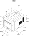
- FIG. 1 is a perspective view showing an external appearance of a dye-sublimation thermal printer 100 (hereinafter, referred to as printer 100).
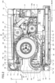
- FIG. 2 is a cross-sectional view taken by a vertical plane that is along a front-rear direction L and passes the center in the width direction W of the printer 100.
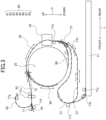
- FIG. 3 is a schematic view that is schematically shown by simplifying FIG. 2 , for clarifying a transport path 80 shown in FIG. 2 .
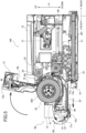
- FIG. 4 is a perspective view showing a condition in which a front top cover 13 of the printer 100 has been opened and a roll-paper storage section 22 has been pulled forward in the front-rear direction L.
- FIG. 5 is a sectional view of the condition of FIG. 4 , corresponding to FIG. 2 .
- the printer 100 shown in the drawings refers to one embodiment of the printer according to the present invention.
- the printer 100 includes a case 10, a sheet-paper storage section 21, a roll-paper storage section 22, a printing section 30, a cutter section 40, a transport means 70, a transport path 80, and a meandering correction mechanism 50.
- the case 10 includes a case body 11, a top cover 12, a front top cover 13, a front center cover 14, and a front bottom cover 15.
- the case body 11 is formed to cover mainly both side surfaces in the width direction W and a rear surface in the front-rear direction L.
- the top cover is disposed to close a top opening in a height direction H of the case body 11 and is formed with a stacker 12a in which a sheet paper 201 (hereinafter, also simply referred to as paper 201) or a paper 203 unwound from a roll paper 202 is stored.
- a sheet paper 201 hereinafter, also simply referred to as paper 201
- a paper 203 unwound from a roll paper 202 is stored.
- a bottom surface 12b of the stacker 12a is formed in an inclined manner to become lower from the rear toward the front, and the paper 201, 203, which has been discharged rearward from an upper outlet 13b of the front top cover 13, is stored on the front side due to the inclination of the bottom surface 12b.
- the front top cover 13 is disposed at the top of the front surface of the printer 100
- a front bottom cover 15 is disposed at the bottom of the front surface of the printer 100
- a front center cover 14 is disposed between the front top cover 13 and the front bottom cover 15 on the front surface of the printer 100.
- the front center cover 14 includes a detachable trash box 16.
- the trash box 16 is disposed below the aforementioned cutter section 40 and is a section to receive cut pieces produced when the paper 201, 203 is cut by the cutter section 40.
- the trash box 16 is attached to the front center cover 14 to be detachable therefrom by an upward sliding relative to the front center cover 14.
- FIGS. 4 and 5 show a condition in which the trash box 16 has been removed.
- the front top cover 13 and the front center cover 14 are provided in an internal drawer unit 60 (one example of a drawer unit).
- the internal drawer unit 60 is housed within the space enclosed by the case body 11 and the top cover 12, and can be pulled forward relative to the case body 11 and the top cover 12 by placing a finger on a fingerhold 14a at the bottom of the front center cover 14 and pulling it forward in the front-rear direction L.
- the internal drawer unit 60 includes, in an integral manner, the roll-paper storage section 22, an ink ribbon 32, and a platen roller 33 of the printing section 30, the cutter section 40, the transport means 70, the transport path 80, and the meandering correction mechanism 50, as well as the front top cover 13 and the front center cover 14.
- the front top cover 13 is supported to be rotatable in the upper rearward direction shown with the arrows in FIGS. 4 and 5 , in a condition that the internal drawer unit 60 has been pulled forward from the space enclosed by the case body 11 and the top cover 12 as shown in FIGS. 4 and 5 , from a condition that the front top cover 13 is closed as shown in FIG. 1 .
- the front top cover 13 is opened by the upper rearward rotation, it opens parts of the front and top of the roll-paper storage section 22. This exposes the roll-paper storage section 22 inside the case 10, enabling the roll paper 202 to be placed into or removed from the roll-paper storage section 22.
- the front top cover 13 includes a front outlet 13a on its front surface and an upper outlet on its rear surface.
- the front outlet 13a is configured to discharge the printed paper 201, 203 forward.
- the upper outlet is configured to discharge the printed paper 201, 203 rearward into the stacker on the top cover 12.
- the front bottom cover 15 is formed as a part on the front surface of the sheet-paper storage section 21 having a tray shape.
- the front bottom cover 15 is a part of the sheet-paper storage section 21.
- the sheet-paper storage section 21 is provided at the bottom of the printer 100 below the roll-paper storage section 22.
- the sheet-paper storage section 21 stores the sheet papers 201 that have been cut to predetermined sizes and stacked in the thickness direction.
- the sheet-paper storage section 21 is provided to be pulled forward relative to the case body 11 and the top cover 12 independently of the internal drawer unit 60 by placing a finger on a fingerhold 15a formed on an upper part of the front bottom cover 15 and pulling the sheet-paper storage section 21 forward in the front-rear direction L.
- the sheet-paper storage section 21 has an open top when pulled forward relative to the case body 11 and the top cover 12, allowing the sheet papers 201 stored inside to be taken in or out through the open top.
- the roll-paper storage section 22 is formed in the internal drawer unit 60.
- the roll-paper storage section 22 is a section to store the roll paper 202 prepared by rolling the elongated paper 203. As shown in FIGS. 2 , 4 , and 5 , the roll-paper storage section 22 stores the roll paper 202 in an orientation in which the axis of the roll paper 202 is parallel with the width direction W of the printer 100.
- the roll-paper storage section 22 is positioned above the sheet-paper storage section 21 when the internal drawer unit 60 is housed within the case 10 as shown in FIG. 2 .
- the roll paper 202 is disposed to rotate counterclockwise as the paper 203 is pulled and unwound from the lower end of the roll paper 202 in the right direction shown in the drawing.
- the printing section 30 is disposed behind the roll-paper storage section 22. Under the control of a controller 95 of the printer 100, the printing section 30 prints on the paper 201, 203 as it passes through a section (the aforementioned printing path 82) of the transport path 80, which extends substantially vertically behind the roll-paper storage section 22.
- the printing section 30 includes a thermal head 31, the ink ribbon 32, and the platen roller 33.
- the ink ribbon 32 transfers the ribbon from a delivery roll 32a to a winding roll 32b in synchronization with the transport of the paper 201, 203, and the sublimation dye applied to the ribbon is transferred onto the paper 201, 203 through diffusion, as a result of the heat generated by the thermal head 31 in contact with the ribbon, thereby printing on the paper 201, 203.
- the ink ribbon 32 is provided in the internal drawer unit 60. As shown in FIGS. 4 and 5 , when the internal drawer unit 60 is pulled forward from the case body 11, the ink ribbon 32 can be drawn forward along an arcuate path above the roll-paper storage section 22, thereby allowing for easy replacement of the ink ribbon 32.
- a platen roller 33 is disposed on the opposite side of the ink ribbon 32 and the thermal head 31 across the paper 201, 203.
- the platen roller 33 presses the paper 201, 203 against the thermal head 31, with the ribbon in between.
- the cutter section 40 is disposed ahead of the roll-paper storage section 22 and inside the front top cover 13. Under the control of the controller 95 of the printer 100, the cutter section 40 cuts the paper 201, 203 in the width direction W passing through a part (the aforementioned discharge path 83) of the transport path 80, which extends forward from above the roll-paper storage section 22. The cut pieces of the paper 201 fall into the trash box 16 disposed below the cutter section 40 and are stored there.
- the transport path 80 is a passage through which the paper 201, 203 is transported. Firstly, a part of the transport path 80 through which the paper 201 is transported will be described.
- the part of the transport path 80 where the sheet paper 201 is transported includes a feeding path 81, the printing path 82, the discharge path 83, the front discharge path 84, the upper discharge path 85, the printing upstream path 86, and a printing downstream path 87.
- the feeding path 81 extends upward from the front end of the sheet-paper storage section 21 and turns back rearward and downward in a space in front of the roll-paper storage section 22 and behind the front center cover 14. Then, the feeding path 81 extends below the roll-paper storage section 22 and above the sheet-paper storage section 21 toward the rear of the roll-paper storage section 22, and then upwardly extends to a position at the rear of the roll-paper storage section 22.
- the feeding path 81 has a space S extending in the thickness direction of the paper 201 such that, even when the sheet paper 201 in transportation is raised in a mountain-like shape in the thickness direction, it is allowed to pass therethrough without catching a bent portion K of the paper 201 in such mountain-like raised state.
- the printing path 82 follows the feeding path 81, extends at the rear of the roll-paper storage section 22 in a manner to rise upwardly along the rear of the roll-paper storage section 22, and extends forward above the roll-paper storage section 22 until it reaches a front part above the roll-paper storage section 22.
- the printing section 30 is disposed at the printing path 82.
- the discharge path 83 follows the printing path 82 and extends forward from the front part above the roll-paper storage section 22 along the front-rear direction L.
- the cutter section 40 is disposed at the discharge path 83.
- the discharge path 83 extends forward of the cutter section 40.
- the front discharge path 84 follows the discharge path 83 and extends forward to the front outlet 13a.
- the upper discharge path 85 follows the discharge path 83 and extends in a curved manner upward and rearward to reach the upper discharge outlet 13b.
- a discharge-path switching member 71 is provided to switch the movement of the paper 201, 203, which has traveled forward in the discharge path 83, either to travel to the upper discharge path 85 or the front discharge path 84.
- the printing upstream path 86 follows the printing path 82 and extends from the front part above the roll-paper storage section 22, curving concentrically around the outer periphery of the roll-paper storage section 22, and continues downward below the roll-paper storage section 22 to a position just before reaching the feeding path 81.
- the printing upstream path 86 is a pathway into which the paper 201 is pulled before being transported to the printing path 82 and printed in the printing section 30.
- the aforementioned printing downstream path 87 is a pathway to which the paper 201 is transported after being transported to the printing path 82 and printed in the printing section 30.
- a part of the paper 201 that has not yet been printed passes through the printing upstream path 86, and a part of the paper 201 that has already been printed passes through the printing downstream path 87.
- the printing-discharge switching flap 72 is provided.
- the printing-discharge switching flap 72 is rotatably configured so that its tip moves up and down under the control of the controller 95. In the condition shown in FIG. 2 , the printing-discharge switching flap 72 has its tip positioned downward. As a result, the paper 201 that has traveled forward in the printing path 82 is redirected to the discharge path 83. On the other hand, when the tip of the printing-discharge switching flap 72 is positioned upward, the paper 201 that has traveled forward in the printing path 82 is redirected to the printing upstream path 86.
- the printing downstream path 87 follows an end portion of the printing path 82 on the side of the feeding path 81.
- the printing downstream path 87 extends from the rear to the front of the roll-paper storage section 22, passing below the roll-paper storage section 22 and the feeding path 81, and above the sheet-paper storage section 21.
- the leading end of the printing downstream path 87 on the front side rises upwardly and smoothly connects to the feeding path 81, which similarly extends upward.
- the paper 201 is printed on the surface that comes into contact with the ink ribbon 32 in the printing path 82, that is, on the surface facing rearward in the front-rear direction L as shown in FIGS. 2 and 3 .
- the printed surface faces downward in the height direction H.
- the printed surface faces forward in the front-rear direction.
- the paper 201 is transported in the feeding path 81 after the printing downstream path 87 joins the feeding path 81, thereby inverting its front and back sides . Therefore, the pathway from the printing downstream path 87 to the feeding path 81, including the feeding path 81, forms a reversing path that reverses the front and back surfaces of the paper 201 after printing on the front surface.
- the part of the transport path 80 includes a roll-paper feeding path 89, in addition to the above-mentioned part where the sheet paper 201 is transported.
- the roll-paper feeding path 89 extends rearward from substantially the bottom of the roll paper 202, which is stored in the roll-paper storage section 22, to an upwardly raised position at the rear of the roll-paper storage section 22.
- a feeding switching flap 73 is provided at a part where the feeding path 81 and the roll-paper feeding path 89 join.
- the feeding switching flap 73 is rotatably provided to displace its tip forward and rearward. In a condition shown in FIG. 2 , the tip of the feeding switching flap 73 is biased toward the front side by a spring, which is omitted from the drawings, such that the paper 201 transported through the feeding path 81 travels to the printing path 82 and that the paper 201 transported from the printing path 82 travels to the printing downstream path 87.
- the paper 203 unwound from the roll paper 202 is printed at the printing section 30 of the printing path 82, the paper 203 remains unseparated from the roll paper 202. Therefore, the feeding switching flap 73 remains pressed toward the rear side in a displaceable range of the tip by a part of the paper 203 passing through the roll-paper feeding path 89.
- the transport means 70 includes a sheet-paper delivery roller 77a, a feeding roller 77b, a reversing roller 77c, a gripping roller 77d, a sending roller 77e, a first discharge roller 77f, a second discharge roller 77g, and a roll-paper delivery roller 77h.
- These transport rollers 77a to 77h are driven, for example, by a single motor, but may be separately driven by at least two motors.
- Each of these transport rollers 77a to 77h comes into contact with the front or back surface of at least one of the sheet paper 201 and the paper 203, and rotates under the control of the controller 95, thereby transporting the paper 201, 203 along the transport path 80.
- the sheet-paper delivery roller 77a is disposed above and near a front-end portion of the sheet-paper storage section 21.
- the sheet-paper delivery roller 77a comes into contact with the topmost sheet paper 201 of the stored sheet paper 201 in the sheet-paper storage section 21 and rotates to deliver the sheet paper 201 to the feeding path 81.
- the sheet-paper delivery roller 77a rotates in a direction opposite to the delivery direction so that the sheet paper 201 delivered to the feeding path 81 is pulled back into the sheet-paper storage section 21.
- the feeding roller 77b is disposed at a position of the feeding path 81 close to the sheet-paper delivery roller 77a.
- the feeding roller 77b comes into contact with the sheet paper 201, which has been delivered to the feeding path 81 by the sheet-paper delivery roller 77a, and transports the sheet paper 201 upward along the feeding path 81.
- the feeding roller 77b also rotates in a direction opposite to the above-mentioned transport direction, thereby pulling the sheet paper 201 backward.
- the reversing roller 77c, the gripping roller 77d, the sending roller 77e, the first discharge roller 77f, the second discharge roller 77g, and the roll-paper delivery roller 77h which will be described in the following, also rotate in directions opposite to their transport directions, similar to the feeding roller 77b, thereby pulling the sheet paper 201 backward.
- the reversing roller 77c is disposed at a part of the feeding path 81 above the feeding roller 77b.
- the reversing roller 77c comes into contact with the sheet paper 201 that has traveled in the feeding path 81 by the feeding roller 77b and transports the sheet paper 201 along the feeding path 81 towards the printing path 82.
- the gripping roller 77d is disposed at a part of the printing path 82 that is on the side close to the feeding path 81 and at a position that is ahead of the tip of the feeding switching flap 73.
- the gripping roller 77d comes into contact with the sheet paper 201, which has been transported to the printing path 82, and transports the sheet paper 201 through the printing section 30 towards the discharge path 83 or the printing upstream path 86.
- the feeding switching flap 73 has been switched forward, thereby allowing the sheet paper 201 transported through the feeding path 81 to proceed to the printing path 82.
- the sending roller 77e is disposed at a part of the discharge path 83 closer to the printing path 82 than the cutter section 40.
- the sending roller 77e comes into contact with the sheet paper 201, which has been transported to the discharge path 83, and transports the sheet paper 201 to the first discharge roller 77f through the cutter section 40.
- the first discharge roller 77f is disposed near an end portion of the discharge path 83 that is on a far side from the printing path 82 and at a position before the discharge-path switching member 71.
- the first discharge roller 77f comes into contact with the sheet paper 201, which has been transported to the discharge path 83, and transports the sheet paper 201 to the front discharge path 84 or the upper discharge path 85 depending on the position of the discharge-path switching member 71.
- the second discharge roller 77g is disposed close to the upper outlet 13b of the upper discharge path 85.
- the second discharge roller 77g comes into contact with the sheet paper 201, which has been transported to the upper discharge path 85, and discharges the sheet paper 201 from the upper outlet 13b into the stacker 12a of the top cover 12.
- the roll-paper delivery roller 77h is disposed at a part of the roll-paper feeding path 89 that is on the side close to the printing path 82 and at a position before the tip of the feeding switching flap 73.
- the roll-paper delivery roller 77h comes into contact with the paper 203, which is wound around the outermost circumference of the roll paper 202 stored in the roll-paper storage section 22 and delivers the paper 203 by the rotation towards the gripping roller 77d.
- the roll-paper delivery roller 77h also rotates in a direction opposite to the delivery direction so that the paper 203 delivered towards the gripping roller 77d is rewound around the roll paper 202 of the roll-paper storage section 22.
- the printer 100 includes, at a position that is closer to the printing upstream path 86 than the gripping roller 77d and is on the pathway of the printing path 82, a first sensor 96 that is configured to detect the passage of a front end 201a in the sending direction of the paper 201 when it is sent to the printing upstream path 86 by the gripping roller 77d.
- the printer 100 includes a second sensor 97 at a position closer to the printing downstream path 87 than the gripping roller 77d and on the pathway of the printing path 82.
- the second sensor 97 is configured to detect the passage of the rear end in the sending direction of the paper 201 when it is sent to the printing upstream path 86 by the gripping roller 77d.
- FIGS. 6 , 7 , and 8 show a condition before correcting the meandering of the paper 201.
- FIG. 6 is a perspective view
- FIG. 7 is a plan view
- FIG. 8 is a schematic view of FIG. 7 .
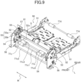
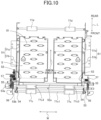
- FIGS. 9 , 10 , and 11 show a condition in which the meandering of the paper 201 is being corrected.
- FIG. 9 is a perspective view, corresponding to FIG. 6 .
- FIG. 10 is a plan view, corresponding to FIG. 7 .
- FIG. 11 is a schematic view, corresponding to FIG. 8 .
- the meandering correction mechanism 50 is configured to correct the meandering of the sheet paper 201, which is transported through the transport path 80, where the sheet paper 201 travels obliquely or changes the direction with respect to the transport direction.
- the meandering correction mechanism 50 includes the feeding path 81 (one example of the transport path), the reversing roller 77c (one example of the drive roller), the gripping roller 77d (one example of the downstream roller), a pair of left and right guide members 51, a pair of left and right movable guide members 52, and a pair of left and right cam members 53.
- the reversing roller 77c is provided in an upstream region of the feeding path 81 in the sending direction of the sheet paper 201.
- the reversing roller 77c is configured to restrict the paper 201 by making contact with the sheet paper 201 and to be movable between a gripping position to send the sheet paper 201 and a retracted position to release the restriction of the sheet paper 201 by moving away from the paper 201.
- the gripping roller 77d is provided in the printing path 82. Since the printing path 82 is provided downstream in the feeding path 81 in the sending direction of the sheet paper 201, the gripping roller 77d is provided downstream in the feeding path 81 in the sending direction of the sheet paper 201. Similar to the reversing roller 77c, the gripping roller 77d is configured to movable between a gripping position to restrict the sheet paper 201 by making contact with the sheet paper 201 that has passed through the feeding path 81 and a retracted position to release the restriction of the sheet paper 201 by moving away from the paper 201.
- the spacing between the reversing roller 77c and the gripping roller 77d along the feeding path 81 is shorter than the length of the sheet paper 201. Therefore, when the front end 201a of the sheet paper 201, which has been sent in the sending direction along the feeding path 81 by the reversing roller 77c, reaches the gripping roller 77d, the rear end of the sheet paper 201 is at a position where it can make contact with the reversing roller 77c.
- the left and right guide members 51 are fixedly provided on both edges of the feeding path 81, respectively.
- the respective guide members 51 are positioned outside of both side edges of the sheet paper 201 passing through the feeding path 81 and include wall surfaces that vertically raised in the thickness direction of the sheet paper 201 from the surface of the feeding path 81. Accordingly, the guide members 51 guide the paper 201 by limiting the positions of both side edges of the sheet paper 201 as the side edges of the sheet paper 201 passing through the feeding path 81 make contact with the raised wall surfaces.
- Each guide member 51 includes a first portion 51b, which is positioned upstream in the sending direction of the paper 201 shown by the arrow in FIG. 7 , and a second portion 51a positioned downstream therein.
- the left and right first portions 51b as a pair are formed to have a spacing that narrows gradually in the sending direction (shown by the arrow) of the sheet paper 201, such that their upstream sections closest to the reversing rollers 77c have a spacing L2 (L2 is 207 [mm] as one example) wider than the width W1 of the paper 201 and that their downstream sections 51d closest to the second portions 51a have a spacing L1 substantially equal to the width W1 of the sheet paper 201, and extend from a first region a1 to a second region a2.
- the first portion 51b and the second portion 51a are formed into one piece.
- the pair of the first portions 51b in the present embodiment is formed so that the spacing therebetween is linearly and gradually narrowed.
- the first portions 51b are not limited to one that is formed linearly and gradually narrowed.
- the second portions 51a are formed to be parallel with each other along the sending direction with the spacing L1 (L1 is 203 [mm] as one example) substantially equal to the width W1 of the sheet paper 201 and are connected with the downstream sections having the narrowest spacing of the first portions 51b.
- the sections of the first portions 51b which have the spacing L2 therebetween wider than the width W1 of the sheet paper 201 and which are closest to the reversing rollers 77c, are positioned in the first region a1, thereby almost certainly sending the sheet paper 201, which is sent by the reversing rollers 77c, into a space between the first portions 51b. Then, the sheet paper 201 is guided and transported by the first portions 51b to the second portions 51a, which have the spacing L1 substantially equal to the width W1 of the sheet paper 201.
- downstream sections 51d in the first portions 51b which are closest to the second portions 51a, extend to the second region a2.
- the left and right movable guide members 52 as a pair, which are arranged in the width direction W, are respectively provided on both side edges of the feeding path 81, upstream of the guide members 51 in the sending direction of the sheet paper 201 and downstream of the reversing rollers 77c therein.
- the movable guide members 52 are also respectively provided on both sides of the feeding path 81.
- the printer 100 may switch the positions in the transport direction of the pair of left and right movable guide members 52 and the reversing rollers 77c to dispose the reversing rollers 77 downstream of the movable guide members 52 and the movable guide members 52 upstream of the reversing rollers 77. Even if these positions are switched, it is possible to apply the same configuration and operation as those in the case of no switch.
- the movable guide members 52 as a pair are formed to be parallel with each other along the sending direction.
- the movable guide members 52 as a pair are each provided on a single common shaft 52a to be slidable in the axial direction.
- the shaft 52a is fixed to the center of the pair of left and right cam members 53. Both ends of the shaft 52a are rotatably supported on left and right frame side plates 56.
- the movable guide members 52 are formed to be positioned outside of both side edges of the paper 201 passing the feeding path 81 and to include wall surfaces vertically raised in the thickness direction of the sheet paper 201.
- the movable guide members 52 are provided to be movable in the width direction W along the shaft 52a between positions away from the side edges of the sheet paper 201 passing the feeding path 81 and positions in contact with both side edges of the sheet paper 201.
- the movable guide members 52 as a pair are provided to be movable between the spacing L2 wider than the width W1 of the sheet paper 201 and the spacing L1 substantially equal to the width W1 of the sheet paper 201. When they have the spacing L1 substantially equal to the width W1 of the sheet paper 201, they take the positions in contact with both side edges of the sheet paper 201.
- the printer 100 may include an adjusting mechanism that limits and adjusts the positions of the movement of the movable guide members 52 as a pair to sides where they are brought into contact with both side edges of the sheet paper 201, within the movable range thereof.
- This adjusting mechanism includes, for example, a pair of abutting portions that abut inner surfaces of the movable guide members 52 as a pair and fixed portions each being fixed at any single position or any of multiple positions in the width direction W (direction orthogonal to the transport direction) of the sheet paper 201. It can be configured by a plate-shape limiting member (adjusting plate, etc.) that is disposed between the movable guide members 52 as a pair and a fixing means (fixing bolts, etc.) that fixes this limiting member.
- the fixed portion is, for example, an elongated hole that extends in the width direction W of the sheet paper 201, and a fixing bolt as a fixing means is inserted into this elongated hole.
- the limiting member is not limited to a single member.
- the limiting member may be separated into a limiting member for one of the pair of movable guide members 52 and another limiting member for the other of the pair of movable guide members 52.
- the movable guide members 52 as a pair have the spacing L2 therebetween wider than the width W1 of the sheet paper 201, they may be positioned to have a spacing wider than that between their positions on extension lines along the front-rear direction L of the upstream ends of the upstream portions 51b of the guide members 51.
- the cam members 53 are integrally rotatable with the shaft 52a about its axis.
- Each of the cam members 53 is integrally formed of a first cam 53a and a second cam 53b.
- the first cam 53a is formed on an outer peripheral surface of the cam member 53.
- a cam surface of the first cam 53a is in abutment with a follower member 55 that is integrally provided with the movable guide member 52.
- the rotation of the cam member 53 displaces the follower member 55, which is biased by a spring 57 inward in the width direction W, and outward in the width direction W, thereby moving the movable guide member 52 in the width direction W.
- the second cam 53b is formed on an inner peripheral surface of the cam member 53.
- the second cam 53b is in abutment with a link plate 54 that supports a shaft 77c1 of the reversing rollers 77c.
- the link plate 54 is rotatably supported about a shaft 77c2 that is supported on left and right frame side plates 56.
- the second cams 53b displace the link plates 54 outward in the radial direction of the cam members 53.
- the link plates 54 rotate about the shaft 77c2, thereby retracting the reversing rollers 77c, which are supported on the shaft 77c1, from their position in abutment with the sheet paper 201 to the retracted position.
- the second cam members 53b are exemplary retracting members that retract the reversing rollers 77c at the gripping position in contact with the paper 201 to the retracted position away from the sheet paper 201, in a condition in which the front end 201a in the sending direction of the paper 201 has reached the downstream portions 51a of the guide members 51.
- the cam members 53 interlock the movable guide members 52 and the reversing rollers 77c. Specifically, when the cam members 53 are in a first rotational position, the reversing rollers 77c are in a position in contact with the sheet paper 201, and the movable guide members 52 are in a position with the spacing L2 away from both side edges of the paper 201. On the other hand, when they are in a second rotational position by the rotation of the cam members, the reversing rollers 77c are in the retracted position not in contact with the sheet paper 201, and the movable guide members 52 take a position with the spacing L1 in contact with both side edges of the sheet paper 201.
- the reversing rollers 77c turn into a condition away from the sheet paper 201. Therefore, before the cam members 53 reach the second rotational position, the reversing rollers 77c turn into a condition where they have reached the retracted position.
- the movable guide members 52 only slightly narrow from the spacing L2. Only when the cam members 53 have reached the second rotational position, they turn to have the spacing L1 and take the position in contact with both side edges of the sheet paper 201.
- the cam members 53 are rotated between the first rotational position and the second rotational position by the control by the controller 95 of the printer 100.
- the controller 95 controls the movement (retraction) of the reversing rollers 77c to the retracted position.
- the sheet paper 201 is once sent to the printing upstream path 86 through the printing path 82 by the control of the controller 95. Upon this, the sheet paper 201 passes through the printing path 82, but the controller 95 does not print on the sheet paper 201. Then, the controller 95 reverses the sending direction by rotating the gripping roller 77d to pass the sheet paper 201 through the printing path 82, and during this passing the controller 95 controls the printing section 30 to conduct printing on the sheet paper 201.
- a part of the sheet paper 201 subjected to the printing on the printing path 82 that is, a part on the front-end side in the sending direction of the sheet paper 201 is sent from the printing path 82 to the printing downstream path 87.
- the length along the printing downstream path 87 between the gripping roller 77d, which sends the sheet paper 201 on the printing path 82, and the reversing roller 77c, which is provided on the feeding path 81 joined by the printing downstream path 87, is set to be shorter than the length in the sending direction of the sheet paper 201.
- the spacings between the other transport rollers 77a to 77h are similar.
- the transport means 70 to send the sheet paper 201 is configured that the pitch between the two adjacent transport means 70 along the transport path 80 is shorter than the length of the sheet paper 201 to be delivered, in order to deliver the sheet paper 201 to be sent along the transport path 80 by each transport roller 77a to 77h constituting the transport means 70.
- the printer 100 moves the reversing roller 77c, with which the front end 201a of the sheet paper 201 during the printing by the printing section 30 is brought into contact, while it is sent by the gripping roller 77d, to the retracted position, which is not in contact with the sheet paper 201, by the control of the controller 95.
- the printer includes a printing section (printing section 30) that conducts printing on a paper (sheet paper 201), a first drive roller (gripping roller 77d) that makes the paper pass through the printing section, and a second drive roller (reversing roller 77c) that is provided downstream of the printing section and the first drive roller in the sending direction of the paper, and is configured that the second drive roller is movable to a retracted position that does not make contact with the paper during the printing by the printing section.
- the printer 100 can prevent the occurrence of uneven printing on the sheet paper 201, due to no contact of the reversing roller 77c with the sheet paper 201 during the printing.
- the printer includes a feeding path (feeding path 81) that sends the paper to the printing section in a manner to reverse the front and back surfaces of the paper, downstream in the sending direction of the transport path (printing downstream path 87) where the paper printed in the printing section passes through.
- the second drive roller is a reversing roller (reversing roller 77c) that sends to the feeding pathway the printed paper sent through the feeding path.
- the second drive roller is a drive roller (feeding roller 77b) that is provided in the vicinity of a feeding roller, which sends the paper delivered from the paper tray (sheet-paper storage section 21), and that sends the paper, which has been sent by the feeding roller, to the feeding path, and the feeding roller and the second drive roller are driven by a single motor.
- the rotational direction of the feeding roller 77b and that of the reversing roller 77c always result in the rotation in the same direction.
- a printer configured by respectively driving the feeding roller 77b and the reversing roller 77c by separate motors can rotate only the feeding roller 77b in the opposite direction, but a printer configured by driving the feeding roller 77b and the reversing roller 77c by a single motor cannot rotate only the feeding roller in the opposite direction.
- the printer 100 can move the reversing roller 77c to the retracted position not in contact with the sheet paper 201. Therefore, even if it is configured by driving the feeding roller 77b and the reversing roller 77c by a single motor, only the rotation of the feeding roller 77b can be transmitted to the sheet paper 201, with no transmission of the rotation of the reversing roller 77c to the paper 201, by rotating the feeding roller 77b and the reversing roller 77c in the opposite directions in a condition in which the reversing roller 77c has been moved to the retracted position.
- the printer 100 is configured by driving the feeding roller 77b and the reversing roller 77c by a single motor, it is possible to pull back only one of the overlapped two sheets of the sheet paper 201 to the sheet-paper storage section 21 to resolve the overlapped state by rotating the feeding roller 77b in the opposite direction in a condition in which the reversing roller 77c has been moved to the retracted position.
- FIG. 12 is a perspective view of a major part, showing a condition in which the paper guide 90 is closed.
- FIG. 13 is a perspective view of the major part, showing a condition in which the paper guide 90 is opened.
- FIG. 14 is a sectional view of a major part, showing a condition in which the paper guide 90 is closed and the reversing roller 77c is in contact with the sheet paper 201.
- FIG. 15 is a sectional view of the major part, showing a condition in which the paper guide 90 is closed and the reversing roller 77c is away from the sheet paper 201.
- FIG. 16 is a sectional view of the major part, showing a condition in which the paper guide 90 is opened.
- the paper guide 90 is a partition plate that covers the transport path 80 by partitioning the transport path 80 in the thickness direction of the sheet paper 201, and is disposed in a manner to partition the outer peripheral side of a reversing section that is a curved region including the reversing roller 77c mounted from the printing downstream path 87 to the feeding path 81 in the printer 100 of the present embodiment, as shown in FIGS. 1 and 3 .
- the paper guide 90 is configured to open and close freely in a manner to be switched between a closed state, as shown in FIG. 12 , in which the transport path 80 (the reversing section as a curved region including the reversing roller 77c mounted from the printing downstream path 87 to the feeding path 81) is covered, and an open state, as shown in FIG. 13 , in which this reversing section is exposed.
- the user manually conducts opening and closing of the paper guide 90.
- the paper guide 90 includes a cover plate 91 and side plates 92 that are respectively formed on both side portions of the cover plate 91 to be integral with the cover plate 91.
- the cover plate 91 is formed like a part of the circumference of a cylinder and covers the reversing section from the outer peripheral side, as shown in FIGS. 14 and 15 .
- Each side plate 92 is formed to rise toward the outside of the circumference of the cylinder with respect to the cover plate 91.
- Each side plate 92 is supported on the shaft 77c2, which is the rotational center of the link plates 54. With this, the paper guide 90 becomes rotatable about the shaft 77c2 similar to the link plates 54, and is switched by this rotation between the above-mentioned closed state ( FIGS. 12 , 14 and 15 ) and open state ( FIGS. 13 and 16 ).
- each side plate 92 is rotatably supported about the shaft 77c2, similar to the link plate 54.
- Each side plate 92 is formed with an elongated hole 92a that allows the shaft 77c1 supporting thereon the reversing rollers 77c to pass therethrough.
- the shaft 77c1 is disposed on the outer side of the cover plate 91 and is passed through the elongated hole 92a formed in each side plate 92.
- the elongated hole 92a is formed to extend along a range where the shaft 77c1 moves by a relative rotation of the link plate 54 about the shaft 77c2, in order to allow the link plate 54 to relatively rotate about the shaft 77c2 with respect to each side plate 92.
- the range that allows a relative rotation of the link plate 54 with respect to each side plate 92 is set to correspond to the range where the shaft 77c1 moves (arc shape centered on the shaft 77c2), when the reversing roller 77c moves between the position in contact with the sheet paper 201 ( FIG. 14 ) and the retracted position away from the sheet paper 201 ( FIG. 15 ) in the closed state of the paper guide 90 ( FIG. 12 ).
- the reversing roller 77c can move between the position in contact with the sheet paper 201 and the retracted position, while the paper guide 90 remains closed.
- the cover plate 91 is formed with two openings 91a along the shaft 77c2.
- the opening 91a is an opening that makes the reversing roller 77c pass therethrough, to expose the reversing roller 77c, which is supported on the shaft 77c1disposed on the outer side of the cover plate 91, to the transport path 80 (feeding path 81) on the inner side of the cover plate 91.
- the reversing rollers 77c In the retracted position of the reversing rollers 77c, the reversing rollers 77c do not project from the inner surface of the cover plate 91 to the side of the transport path 80. Therefore, the retraction control of the reversing rollers 77c in the printing prevents the front edge of the sheet paper 201 during the printing from being caught by the reversing rollers 77c, thereby smoothly sending it along the inner surface of the cover plate 91.
- the reversing rollers 77c are not configured by a long single object along the shaft 77c1, but are arranged as two objects distributed in the axial direction.
- the openings 91a formed in the cover plate 91 are not a single long opening in the axial direction, but are formed as two separate openings corresponding to the reversing rollers 77c.
- the above-configured printer 100 prints on the sheet paper 201, as follows.
- the following printing operation on the sheet paper 201 is an exemplary operation of the printer 100.
- the printer 100 delivers a single sheet of the sheet paper 201 at the top layer of a stack of the sheet paper 201 stored in the sheet-paper storage section 21 by rotating the sheet-paper delivery roller 77a (see FIG. 2 ) and transports that in the feeding path 81 by the rotation of the feeding roller 77b and the rotation of the subsequent reversing roller 77c.
- the cam member 53 is at the first rotational position. Therefore, the reversing rollers 77c are at the position to restrict the sheet paper 201 by making contact with the sheet paper 201, and the movable guide members 52 are at the position away from both side edges of the sheet paper 201 with the spacing L2.
- the sheet paper 201 which has been sent through the feeding path 81, may turn into an oblique posture condition that is inclined relative to the sending direction or a meandering condition through the travelling direction change caused by the uneven frictional force when making contact with the reversing rollers 77c. Even in such condition, the front end 201a of the sheet paper 201 is sent within the range of the first portions 51b formed with the spacing L2 wider than the width W1 of the sheet paper 201.
- the width between the first portions 51b becomes narrower as it proceeds in the sending direction, when the sheet paper 201 proceeds obliquely or meanders, either of the left and right side edges of the sheet paper 201 starts making contact with the first portion 51b, before the front end 201a of the sheet paper 201 reaches portions connected with the second portions 51a with the narrowest width therebetween.
- the front end 201a of the sheet paper 201 which has been sent with an obliquely inclined posture, should proceed straight along the sending direction with such posture that is still obliquely inclined, but the direction, in which a portion on the side of the front end 201a moves, deviates from the sending direction of the side of the rear end 201b of the sheet paper 201 due to correcting the sending direction to be along the first portion 51b.
- the moving direction of a portion on the side of the front end 201a in a single sheet of the paper 201 is limited by the first portion 51b, and a portion on the side of the rear end 201b moves in the sending direction in a still inclined manner under a restriction by the reversing rollers 77c.
- the moving direction of a portion on the side of the front end 201a of the sheet paper 201 becomes different from that of a portion on the side of the rear end 201b. Therefore, an intermediate portion between the portion on the side of the front end 201a and that of the rear end 201b is subject to stress that is uneven in the width direction W.
- the sheet paper 201 is bent in the thickness direction to release the uneven stress, so that one side in the width direction W (side where the direction of the front end 201a relative to that of the rear end 201b becomes inside in the width direction) turns into a mountain-like raised state in the thickness direction.
- both side edges of the front end 201a make contact with the second portions 51a, respectively.
- a part on the side of the front end 201a of the sheet paper 201 is corrected to have the original normal posture with both side edges that are parallel with each other along the sending direction.
- the mountain-like raised state of the sheet paper 201 refers to a state in which the sheet paper 201 has been deformed into a protrusion shape even slightly in the thickness direction from a flat state extending straight in the sending direction.
- the mountain-like refers to one deformed into a protrusion shape in the thickness direction of the sheet paper 201, regardless of whether it is perceived as a mountain-like shape or not and regardless of the height (deformation amount) of the bent portion K or the extent of the bent range.
- the feeding path 81 includes a space S that accommodates the bent portion K of the sheet paper 201 in the mountain-like raised state in the thickness direction and that extends in the thickness direction of the sheet paper 201. If there were no such space S, the sheet paper 201 would not be formed with the bent portion K in the feeding path 81 during its transport, but plastic deformation would occur in another part of the sheet paper 201. For example, when the sheet paper 201 sent with an obliquely inclined posture is guided by the guide members 51, a front end corner portion in the sending direction of the sheet paper 201 is sent out by the reversing rollers 77c in a condition in contact with an inner wall constituting the guide member 51.
- the space S possessed by the feeding path 81 corresponds to "a space extending in a thickness direction of the sheet paper" in the present invention, even if the bent portion K of the sheet paper 201 is within the height of the guide member 51 (below the height of the wall surface of the guide member 51).
- the gripping rollers 77d move to a retracted position by the control of the controller 95 to turn into a condition not in contact with the sheet paper 201.
- the reversing rollers 77c further send the sheet paper 201 by the control of the controller 95.
- the reversing rollers 77c stop sending the sheet paper 201.
- the cam members 53 begin to rotate from the first rotational position toward the second rotational position by the control of the controller 95.
- the reversing rollers 77c turn into a condition in which they are away from the sheet paper 201 and have moved to the retracted position.
- a portion on the side of the rear end 201b of the sheet paper 201 is released from the restraint by the reversing rollers 77c and turns into a free condition in which it is freely movable.
- a portion on the side of the rear end 201b of the sheet paper 201 which has turned into a free state, is corrected to the normal posture in which both side edges are parallel with the sending direction, to follow the posture of a portion on the side of the front end 201a, with respect to the portion on the side of the front end 201a corrected to the normal posture by the limitation of the second portions 51a, by the restoring force of the bent portion K (force by which the bent portion K tries to restore a flat state) in a mountain-like raised state in the intermediate portion.
- the printer 100 of the present embodiment can correct the overall posture of a single sheet of the paper 201 to the normal posture, in which both side edges are parallel with the sending direction, by only the action of the guide members 51 and the movement of the reversing rollers 77c to the retracted position.
- the cam members 53 rotate further toward the second rotational position by the control of the controller 95. With this, the left and right movable guide members 52 as a pair are displaced to narrow the spacing therebetween.
- the cam members 53 reach the second rotational position, the movable guide members 52 are brought into contact with both side edges of the sheet paper 201 and can further securely correct the posture of the sheet paper 201 to the normal posture (posture with both side edges parallel along the sending direction).
- the second cams 53b press the link plates 54 outward in the radial direction of the cam members 53, thereby rotating the link plates 54 about the shaft 77c2 and rotating the shaft 77c1 forward which is supported on the link plates 54.
- the reversing rollers 77c provided on the shaft 77c1 move to the retracted position away from the sheet paper 201 sandwiched between the reversing rollers 77c and reversing follower rollers 77c3.
- the cam surfaces of the first cams 53a are displaced inward in the width direction W, thereby displacing the follower members 55 inward in the width direction W which are in contact with the cam surfaces of the first cams 53a and are biased inward in the width direction W by the springs.
- the movable guide members 52 which are integral with the follower members 55, are also displaced inward in the width direction W, resulting in the narrowed spacing L1 between the movable guide members 52 as a pair.
- the movable guide members 52 as a pair respectively push side edges on the side of rear end 201b of the sheet paper 201, inward in the width direction W, which are in a condition not restrained by the gripping rollers 77d and the reversing rollers 77c.
- the spacing L2 between the movable guide members 52 as a pair is substantially equal to the width W1 of the sheet paper 201, and each movable guide member 52 is disposed on an extension line in the front-rear direction L of the downstream portion 51a of the guide member 51.
- the movable guide members 52 push a portion on the side of the rear end 201b of the sheet paper 201 inward in the width direction W to respectively bring both side edges on the side of the rear end 201b of the sheet paper 201 into contact with the movable guide members 52, thereby correcting the positions of both side edges.
- the printer 100 of the present embodiment can surely correct the sheet paper 201 to the normal posture by the movable guide members 52.
- the controller 95 After the sheet paper 201 is corrected to the normal posture, the controller 95 returns the gripping rollers 77d from the retracted position to the gripping position in contact with the sheet paper 201. With this, the sheet paper 201 is restrained by the gripping rollers 77d in a condition in which its overall posture has been corrected to the normal posture.
- the sheet paper 201 is sent from the feeding path 81 to the printing path 82, while maintaining the normal posture.
- the cam members 53 are returned from the second rotational position to the first rotational position by the control of the controller 95, thereby returning the spacing between the movable guide members 52 to the wide spacing L2 and returning the reversing rollers 77c to the position where the sheet paper 201 can be gripped.
- the sheet paper 201 which has passed through the printing path 82, is guided to the printing upstream path 86 by switching the printing-discharge switching flap 72.
- the gripping rollers 77d reverse (their rotational direction becomes opposite) so that the sheet paper 201 travels to the printing downstream path 87, while passing through the printing path 82 and being printed on the front surface of the sheet paper 201.
- the front end thereof travels to the feeding path 81 and makes contact with the reversing rollers 77c, followed by being transported again through the feeding path 81 by the rotation of the reversing rollers 77c.
- the sheet paper 201 sent from the printing downstream path 87 to the feeding path 81 turns into a condition in which its front and back surfaces have been reversed.
- meandering of the sheet paper 201 is corrected again by the meandering correction mechanism 50, thereby correcting the sheet paper 201 to the normal posture.
- the sheet paper 201 with the corrected posture is guided from the printing path 82 to the printing upstream path 86.
- the printing downstream path 87 in addition to the feeding path 81, which is also a path for reversing the front and back surfaces of the sheet paper 201 with the printed front surface, also may include the above-mentioned meandering correction mechanism.
- the printing downstream path 87 corresponds to the transport path
- the gripping rollers 77d correspond to the drive rollers
- the reversing rollers 77c correspond to the downstream rollers. Therefore, a pair of left and right guide members 51 is provided at a portion close to the reversing rollers 77c in the printing downstream path 87.
- the printer 100 may include the guide members 51 in the printing upstream path 86 and/or the discharge path 83, too.
- the sheet paper 201 subjected to the meandering correction is returned from the printing upstream path 86 to the printing path 82, the back surface of the sheet paper 201 is printed in the printing section 30, and at the same time it travels to the printing downstream path 87.
- the sheet paper 201 which has completed the printing on the back surface by traveling from the printing path 82 to the printing downstream path 87, passes through the printing path 82 by reversing the rotational direction of the gripping rollers 77d and then is transported to the discharge path 83 by switching the printing-discharge switching flap 72.
- the sheet paper 201 sent to the discharge path 83 is passed from the gripping roller 77d to the sending roller 77e.
- the sheet paper 201 travels forward through the cutter section 40 by the rotation of the sending roller 77e.
- the cutter section 40 cuts an unnecessary part at the rear end in the sending direction of the sheet paper 201.
- the cut-off unnecessary part falls into the trash box 16 (see FIG. 2 ) and is stored inside the trash box 16.
- the sheet paper 201 travels forward by the rotation of the sending roller 77e and is passed to the first discharge roller 77f.
- the sheet paper 201 is transported by the rotation of the first discharge roller 77f.
- the sheet paper 201 is guided to the upper discharge path 85 and is discharged from the upper outlet 13b into the stacker 12a by the rotation of the second discharge roller 77g which is disposed close to the upper outlet 13b.
- the sheet paper 201 is guided to the front discharge path 84 and is discharged from the front outlet 13a to the outside.
- the printer 100 conducts printing by the printing section 30, while sending the sheet paper 201 from the printing path 82 to the printing downstream path 87, not only when printing on the front surface, but also when printing on the back surface.
- the ends in the length direction of the sheet paper 201 are also reversed.
- one end in the length direction of the sheet paper 201 is defined as, for example, an end A and the other end is defined as, for example, an end B
- the sheet paper 201 is sent with the end A as the front end.
- the front end in the sending direction of the sheet paper 201 is reversed between the end A and the end B. Therefore, when printing on the back surface of the sheet paper 201, the sheet paper 201 is sent with the end B as the front end.
- the printing on the front surface of the sheet paper 201 is conducted at a position with respect to, for example, the end A, and the printing on the back surface of the sheet paper 201 is conducted at a position with respect to, for example, the end B.
- the printing content approaches the end A on the front surface of the sheet paper 201, and it approaches the end B on the back surface thereof.
- the printing contents approach different ends on the front and back surfaces of the sheet paper 201. Even if one tries to cut off a marginal area with no printing content thereon, such cutting off is impossible, because the marginal areas do not match with each other between the front and back surfaces of the sheet paper 201.
- the printer 100 of the present embodiment controls the sending of the sheet paper 201 by fixing the reference position in sending the sheet paper at a constant position of the sheet paper 201 itself, regardless of whether printing is conducted on the front surface or back surface of the sheet paper 201.
- the controller 95 controls the sending by fixing the reference in sending the sheet paper 201 at a constant position of the sheet paper 201 itself such that the printing contents on both front and back surfaces of the sheet paper 201 approach either of the ends A and B.
- the printer 100 includes the first sensor 96 and the second sensor 97.
- Each of the first sensor 96 and the second sensor 97 is an optical sensor that detects the passage of the sheet paper, for example, by the change in light intensity due to the passage of the sheet paper 201.
- the first sensor 96 is provided at a position on the downstream side of the printing section 30 (the side close to the printing upstream path 86) in the printing path 82.
- the first sensor 96 detects the front end of the sheet paper 201 in the sending direction, when the sheet paper 201 is sent from the printing path 82 to the printing upstream path 86.
- the second sensor 97 is provided on the upstream side in the printing path 82 (the side close to the feeding path 81) and at a position on the upstream side of the gripping rollers 77d.
- the second sensor 97 detects the front end of the sheet paper 201 in the sending direction, when the sheet paper 201 is sent from the printing path 82 to the printing downstream path 87.
- the controller 95 sets the printing start position based on the detection result by the first sensor 96.
- the controller 95 sets that based on the detection result by the second sensor 97.
- the controller 95 firstly sends the sheet paper 201 by the gripping rollers 77d from the printing path 82 to the printing upstream path 86. Upon this, the first sensor 96 detects the front end (e.g., end A) in the sending direction of the sheet paper 201.
- the controller 95 sends the sheet paper 201 to the printing upstream path 86 by the gripping rollers 77d by a predetermined first length (e.g., length M1), using the time when the first sensor 96 detects the end A of the sheet paper as the sending reference.
- a predetermined first length e.g., length M1
- the predetermined first length is set as a predetermined first number of steps by which the controller 95 drives the step motor.
- the first length is set as a length longer than the length (e.g., length M0) of the printing content on the front surface (M1 > M0).
- the controller 95 controls the rotational direction of the gripping rollers 77d to the opposite direction to send the sheet paper 201 from the printing path 82 to the printing downstream path 87
- the controller 95 controls the printing section 30 to start printing on the front surface of the sheet paper 201.
- the front end in the sending direction of the sheet paper 201 is the end B, but printing on the front surface of the sheet paper 201 is conducted by using the end A of the sheet paper 201 as the reference.
- the sheet paper 201 with the end B as the front end in the sending direction is sent from the printing downstream path 87 to the feeding path 81 by the reversing rollers 77c, thereby reversing the front and back surfaces thereof.
- the sheet paper 201 with the end B as the front end in the sending direction which has been sent to the feeding path 81 and reversed, is guided to the printing path 82 and is further sent to the printing upstream path 86.
- the second sensor 97 detects the rear end (end A) of the sheet paper 201.
- the controller 95 sends the sheet paper 201 to the printing upstream path 86 by the gripping rollers 77d by a predetermined second length (e.g., length M2), using the time when the second sensor 97 detects the end A of the sheet paper 201 as the sending reference.
- the predetermined second length is set as a predetermined second number of steps by which the controller 95 drives the step motor.
- the controller 95 controls the rotational direction of the gripping rollers 77d in the opposite direction to send the sheet paper 201 from the printing path 82 to the printing downstream path 87
- the controller 95 controls the printing section 30 to start printing on the front surface of the sheet paper 201.
- the front end in the sending direction of the sheet paper 201 is the end A, but printing on the back surface of the sheet paper 201 is conducted by using the end A of the sheet paper 201 as the reference.
- the back surface of the sheet paper 201 will have a margin from the end A to the position of the second length (M2). It starts printing of the printing content from the second position toward the end B, to print by the length of the printing content from the position of the second length from the end A
- the printer 100 includes the gripping rollers 77d as a transport means to send the sheet paper 201, the printing section 30 to print on the sheet paper 201 while the sheet paper 201 is sent in one direction by the gripping rollers 77d, and the controller 95 to control the sending of the sheet paper 201 by setting the reference position in sending the sheet paper 201 at a specific position of the sheet paper 201 itself, irrespective of the front or back surface of the sheet paper 201, when the printing section 30 conducts printing on the front surface of the sheet paper 201 and when it conducts printing on the back surface of the sheet paper 201.
- the printer 100 sets one end in the sending direction of the sheet paper 201 as the reference position for the sending.
- the printer 100 includes the first sensor 96 and the second sensor 97, which detect one end of the sheet paper 201, respectively upstream and downstream of the gripping rollers 77d as a transport means in the sending direction of the sheet paper 201.
- the controller 95 sets the reference position in the sending at a specific position by a switching use of the detection result by the upstream first sensor 96 and that by the downstream second sensor 97 when printing on the front and back surfaces of the sheet paper 201.
- the printer 100 of the present embodiment can correct meandering of the sheet paper 201 by the meandering correction mechanism 50 to correct the posture and orientation of the sheet paper 201.
- the pair of left and right cam members 53 is fixed to the shaft 52a. Therefore, it is possible to rotate the left and right cam members 53 in an interlocking manner by the rotation of the shaft 52a. This can displace the pair of left and right movable guide members 52 in an interlocking manner in the width direction W, too.
- the printer 100 of the present embodiment can be configured by only one motor to rotate the shaft 52a, such that meandering of the sheet paper 201 can be corrected by a simple structure with fewer parts, as compared with one in which each movable guide member 52 is provided with a motor to move the same.
- the second cams 53b as retracting members that retract the reversing rollers 77c to the position not in contact with the sheet paper 201, and the first cams 53a that move the movable guide members 52 within a movable range are integrally formed. Therefore, it is possible to interlock the movement (retraction to the retracted position) of the reversing rollers 77c and the movement (movement to the positions respectively in contact with both side edges of the sheet paper 201) of the movable guide members 52.
- the printer 100 of the present embodiment was described as performing only once the retraction of the reversing rollers 77c from the sheet paper 201 and the pressing of the movable guide members 52 inward in the width direction W against both side edges of the sheet paper 201. However, it is optional to press multiple times both side edges of the sheet paper 201 inward in the width direction W by repeating multiple times the forward rotation and the reverse rotation of the cam members 53 between the first rotational position and the second rotational position.
- the movable guide members 52 can impact on both side edges of the sheet paper 201 in a manner to tap them inward in the width direction W, thereby increasing the effect of correcting meandering of the sheet paper 201.
- the printer 100 of the present embodiment can move the reversing rollers 77c to the retracted position during printing ( FIG. 15 ), while the paper guide 90 remains closed ( FIG. 12 ) without opening the same ( FIGS. 13 and 16 ).
- the printer 100 can also turn the reversing rollers 77c together with the paper guide 90 into a condition away from the reversing section by opening the paper guide ( FIGS. 13 and 15 ).
- the printer 100 can improve accessibility to the reversing section, thereby facilitating removal of the sheet paper 201 jammed in the reversing section.
- the two openings 91a which are formed through the cover plate 91 and allow the reversing rollers 77c to pass therethrough, are distributed along the axial direction.
- This configuration is such that a plate surface of the cover plate 91, which is not an opening, is left between the two openings 91a.
- the edge of the opening is elongated in the axial direction, resulting in a condition in which the plate surface of the cover plate 91 is not left behind.
- the openings 91a allowing the reversing rollers 77c to pass therethrough are made into a single opening that is long in the axial direction, there is no portion within the single opening 91a that supports the sheet paper 201 over a long width range of the opening 91a.
- the front end 201a of the sheet paper 201 tends to be projectingly deformed so as to enter the opening 91a.
- the printer 100 allows the portion of the plate surface left behind between the two narrow-width openings 91a to support the sheet paper 201. Therefore, even if the sheet paper 201 is distorted to make an easy deformation toward the side of the openings 91a, it is hardly deformed to the extent that it enters the narrow-width openings 91a.
- the printer 100 of the present embodiment showed an example in which an oblique traveling of the sheet paper 201 is corrected by using guide members (guide members 51) and movable guide members (movable guide members 52).
- the printer according to the present invention is, however, not limited to one including movable guide members. In other words, the printer 100, depending on its use, may not be provided with movable guide members (movable guide members 51), when an oblique traveling of the sheet paper 201 is sufficiently corrected by only guide members (guide members 51).
- the printer 100 of the present embodiment is a dye-sublimation thermal printer, but the printer according to the present invention is not limited to the dye-sublimation thermal printer. It may be another printing-type printer other than the dye-sublimation thermal printer.
- the printer according to the present invention may be a thermal printer other than dye-sublimation thermal printers, a non-thermal printer, such as an inkjet printer, or any other printing-type printer.
- the printer 100 of the present embodiment has been described as printing on both of the front and back surfaces of the sheet paper 201, but the printer according to the present invention may be a printer that prints on only one surface of the sheet paper.
- the printer 100 of the present embodiment is a printer that can print on the long roll paper 202 as well as on the sheet paper 201 pre-cut to a predetermined length, but the printer according to the present invention may be a printer that prints only on sheet paper, that is, one not capable of accommodating roll paper.
Landscapes
- Engineering & Computer Science (AREA)
- Mechanical Engineering (AREA)
- Registering Or Overturning Sheets (AREA)
- Handling Of Sheets (AREA)
- Separation, Sorting, Adjustment, Or Bending Of Sheets To Be Conveyed (AREA)
- Handling Of Continuous Sheets Of Paper (AREA)
Abstract
Description
- The present invention relates to a printer.
- A printer, which prints on paper cut to a predetermined length (sheet paper (cut paper)), sends the paper one sheet at a time to a transport path by a drive roller. The transport path extends from a paper storage section, where the paper is stored, to an outlet, where the paper is discharged, through a printing section to print on the paper. The paper is sent along the transport path by a sequential passing to a plurality of drive rollers provided on the transport path (see, for example, Patent Document 1).
- Here, while the paper is sent by the drive rollers, the paper may meander due to the posture change or the sending direction change. If the paper meanders, a part of the paper may deviate from the region of the transport path where the paper is supposed to pass, thereby causing a misprinting on the paper or a paper jamming inside the printer.
- Thus, some printers include a meandering correction mechanism that corrects the meandering of the paper by tapping at least one side edge of the paper, which is sent along the transport path, from the outside in the width direction of the paper.
- [Patent Literature 1]
JP 5987688 - The above-mentioned meandering correction mechanism is, however, composed of many components, thereby complicating the structure and increasing costs.
- The present invention has been made in view of the above situation, and its object is to provide a printer that can correct the meandering of paper, while preventing paper jamming, with a simple structure having a small number of components.
- The present invention provides a printer including a transport path that a sheet paper passes therethrough; a drive roller that sends the sheet paper along the transport path, the drive roller being provided in an upstream region in a sending direction of the sheet paper of the transport path; a downstream roller that is provided downstream in the sending direction of the transport path, the downstream roller restraining the sheet paper that has passed through the transport path; and a pair of guide members that are disposed outside of both side edges of the sheet paper passing through the transport path to guide the sheet paper by limiting positions of both side edges of the sheet paper, wherein each of the pair of guide members comprises a first portion positioned upstream in the sending direction and a second portion positioned downstream therein, wherein a spacing between the pair of guide members is wider than a width of the paper at sections of the first portions, which are closest to the drive roller, narrows gradually in the sending direction of the paper, is formed to be equal to the width of the sheet paper at sections of the first portions, which are closest to the second portions, and is formed to be equal to the width of the sheet paper at the second portions, wherein, when an area between the drive roller and the second portions is halved into a first region upstream in the sending direction and a second region downstream therein, the sections of the first portions, which are closest to the drive roller, are disposed to be positioned in the first region, wherein the transport path has a space extending in a thickness direction of the sheet paper, such that the space can accommodate a bent portion of the sheet paper in a mountain-like raised state between a front end portion of the sheet paper, of which direction has been corrected due to a limitation by the second portions, and a rear end portion of the sheet paper, which has been restricted by the drive roller.
- The printer according to the present invention can correct the meandering of paper, while preventing paper jamming, with a simple structure having a small number of components.
-
- [
FIG. 1] FIG. 1 is a perspective view showing an external appearance of a dye-sublimation thermal printer (hereinafter, referred to as printer). - [
FIG.2] FIG. 2 is a cross-sectional view taken by a vertical plane that is along a front-rear direction L and passes the center in the width direction W of the printer. - [
FIG.3] FIG. 3 is a schematic view that is schematically shown by simplifyingFIG. 2 , for clarifying a transport path shown inFIG. 2 . - [
FIG.4] FIG. 4 is a perspective view showing a condition in which a front upper cover of the printer has been opened and a roll-paper storage section has been pulled forward in the front-rear direction L. - [
FIG.5] FIG. 5 is a sectional view of the condition shown inFIG. 4 , corresponding toFIG. 2 . - [
FIG.6] FIG. 6 is a perspective view showing a condition before correcting the meandering of the paper. - [
FIG.7] FIG. 7 is a plan view showing the condition before correcting the meandering of the paper. - [
FIG.8] FIG. 8 is a schematic view ofFIG. 7 , showing the condition before correcting the meandering of the paper. - [
FIG.9] FIG. 9 is a perspective view showing a condition in which the meandering of paper is being corrected, corresponding toFIG. 6 . - [
FIG.10] FIG. 10 is a plan view showing the condition in which the meandering of paper is being corrected, corresponding toFIG. 7 . - [
FIG.11] FIG. 11 is a schematic view ofFIG. 10 , showing the condition in which the meandering of paper is being corrected. - [
FIG.12] FIG. 12 is a perspective view of a major part, showing a condition in which a paper guide is closed. - [
FIG.13] FIG. 13 is a perspective view of the major part, showing a condition in which the paper guide is opened. - [
FIG.14] FIG. 14 is a sectional view of a major part, showing a condition in which the paper guide is closed and reversing rollers are in contact with the paper. - [
FIG.15] FIG. 15 is a sectional view of the major part, showing a condition in which the paper guide is closed and the reversing rollers are away from the paper. - [
FIG.16] FIG. 16 is a sectional view of the major part, showing a condition in which the paper guide is opened. - An embodiment of the printer according to the present invention will be described in the following with reference to the drawings.
- <Configuration>
FIG. 1 is a perspective view showing an external appearance of a dye-sublimation thermal printer 100 (hereinafter, referred to as printer 100).FIG. 2 is a cross-sectional view taken by a vertical plane that is along a front-rear direction L and passes the center in the width direction W of theprinter 100.FIG. 3 is a schematic view that is schematically shown by simplifyingFIG. 2 , for clarifying atransport path 80 shown inFIG. 2 .FIG. 4 is a perspective view showing a condition in which afront top cover 13 of theprinter 100 has been opened and a roll-paper storage section 22 has been pulled forward in the front-rear direction L.FIG. 5 is a sectional view of the condition ofFIG. 4 , corresponding toFIG. 2 . - The
printer 100 shown in the drawings refers to one embodiment of the printer according to the present invention. Theprinter 100 includes acase 10, a sheet-paper storage section 21, a roll-paper storage section 22, aprinting section 30, acutter section 40, a transport means 70, atransport path 80, and ameandering correction mechanism 50. - (Case) As shown in
FIG. 1 , thecase 10 includes acase body 11, atop cover 12, afront top cover 13, afront center cover 14, and afront bottom cover 15. Thecase body 11 is formed to cover mainly both side surfaces in the width direction W and a rear surface in the front-rear direction L. - The top cover is disposed to close a top opening in a height direction H of the
case body 11 and is formed with astacker 12a in which a sheet paper 201 (hereinafter, also simply referred to as paper 201) or a paper 203 unwound from aroll paper 202 is stored. - As shown in
FIG. 2 , abottom surface 12b of thestacker 12a is formed in an inclined manner to become lower from the rear toward the front, and thepaper 201, 203, which has been discharged rearward from anupper outlet 13b of thefront top cover 13, is stored on the front side due to the inclination of thebottom surface 12b. - The
front top cover 13 is disposed at the top of the front surface of theprinter 100, afront bottom cover 15 is disposed at the bottom of the front surface of theprinter 100, and afront center cover 14 is disposed between thefront top cover 13 and thefront bottom cover 15 on the front surface of theprinter 100. - The
front center cover 14 includes adetachable trash box 16. Thetrash box 16 is disposed below theaforementioned cutter section 40 and is a section to receive cut pieces produced when thepaper 201, 203 is cut by thecutter section 40. Thetrash box 16 is attached to thefront center cover 14 to be detachable therefrom by an upward sliding relative to thefront center cover 14.FIGS. 4 and5 show a condition in which thetrash box 16 has been removed. - As shown in
FIGS. 4 and5 , thefront top cover 13 and thefront center cover 14 are provided in an internal drawer unit 60 (one example of a drawer unit). Theinternal drawer unit 60 is housed within the space enclosed by thecase body 11 and thetop cover 12, and can be pulled forward relative to thecase body 11 and thetop cover 12 by placing a finger on afingerhold 14a at the bottom of thefront center cover 14 and pulling it forward in the front-rear direction L. - The
internal drawer unit 60 includes, in an integral manner, the roll-paper storage section 22, anink ribbon 32, and aplaten roller 33 of theprinting section 30, thecutter section 40, the transport means 70, thetransport path 80, and themeandering correction mechanism 50, as well as thefront top cover 13 and thefront center cover 14. - The
front top cover 13 is supported to be rotatable in the upper rearward direction shown with the arrows inFIGS. 4 and5 , in a condition that theinternal drawer unit 60 has been pulled forward from the space enclosed by thecase body 11 and thetop cover 12 as shown inFIGS. 4 and5 , from a condition that thefront top cover 13 is closed as shown inFIG. 1 . When thefront top cover 13 is opened by the upper rearward rotation, it opens parts of the front and top of the roll-paper storage section 22. This exposes the roll-paper storage section 22 inside thecase 10, enabling theroll paper 202 to be placed into or removed from the roll-paper storage section 22. - The
front top cover 13 includes afront outlet 13a on its front surface and an upper outlet on its rear surface. Thefront outlet 13a is configured to discharge the printedpaper 201, 203 forward. The upper outlet is configured to discharge the printedpaper 201, 203 rearward into the stacker on thetop cover 12. - As shown in
FIGS. 2 and5 , thefront bottom cover 15 is formed as a part on the front surface of the sheet-paper storage section 21 having a tray shape. In other words, thefront bottom cover 15 is a part of the sheet-paper storage section 21. - (Sheet-paper Storage Section) As shown in
FIG. 2 , the sheet-paper storage section 21 is provided at the bottom of theprinter 100 below the roll-paper storage section 22. The sheet-paper storage section 21 stores thesheet papers 201 that have been cut to predetermined sizes and stacked in the thickness direction. - The sheet-
paper storage section 21 is provided to be pulled forward relative to thecase body 11 and thetop cover 12 independently of theinternal drawer unit 60 by placing a finger on afingerhold 15a formed on an upper part of thefront bottom cover 15 and pulling the sheet-paper storage section 21 forward in the front-rear direction L. The sheet-paper storage section 21 has an open top when pulled forward relative to thecase body 11 and thetop cover 12, allowing thesheet papers 201 stored inside to be taken in or out through the open top. - (Roll-paper Storage Section) As mentioned above, the roll-
paper storage section 22 is formed in theinternal drawer unit 60. The roll-paper storage section 22 is a section to store theroll paper 202 prepared by rolling the elongated paper 203. As shown inFIGS. 2 ,4 , and5 , the roll-paper storage section 22 stores theroll paper 202 in an orientation in which the axis of theroll paper 202 is parallel with the width direction W of theprinter 100. - The roll-
paper storage section 22 is positioned above the sheet-paper storage section 21 when theinternal drawer unit 60 is housed within thecase 10 as shown inFIG. 2 . InFIG. 2 , theroll paper 202 is disposed to rotate counterclockwise as the paper 203 is pulled and unwound from the lower end of theroll paper 202 in the right direction shown in the drawing. - (Printing Section) The
printing section 30 is disposed behind the roll-paper storage section 22. Under the control of acontroller 95 of theprinter 100, theprinting section 30 prints on thepaper 201, 203 as it passes through a section (the aforementioned printing path 82) of thetransport path 80, which extends substantially vertically behind the roll-paper storage section 22. - The
printing section 30 includes athermal head 31, theink ribbon 32, and theplaten roller 33. Theink ribbon 32 transfers the ribbon from adelivery roll 32a to a windingroll 32b in synchronization with the transport of thepaper 201, 203, and the sublimation dye applied to the ribbon is transferred onto thepaper 201, 203 through diffusion, as a result of the heat generated by thethermal head 31 in contact with the ribbon, thereby printing on thepaper 201, 203. - The
ink ribbon 32 is provided in theinternal drawer unit 60. As shown inFIGS. 4 and5 , when theinternal drawer unit 60 is pulled forward from thecase body 11, theink ribbon 32 can be drawn forward along an arcuate path above the roll-paper storage section 22, thereby allowing for easy replacement of theink ribbon 32. - A
platen roller 33 is disposed on the opposite side of theink ribbon 32 and thethermal head 31 across thepaper 201, 203. Theplaten roller 33 presses thepaper 201, 203 against thethermal head 31, with the ribbon in between. - (Cutter Section) The
cutter section 40 is disposed ahead of the roll-paper storage section 22 and inside the fronttop cover 13. Under the control of thecontroller 95 of theprinter 100, thecutter section 40 cuts thepaper 201, 203 in the width direction W passing through a part (the aforementioned discharge path 83) of thetransport path 80, which extends forward from above the roll-paper storage section 22. The cut pieces of thepaper 201 fall into thetrash box 16 disposed below thecutter section 40 and are stored there. - (Transport Path) The
transport path 80 is a passage through which thepaper 201, 203 is transported. Firstly, a part of thetransport path 80 through which thepaper 201 is transported will be described. - As shown by a single-point chain line in
FIGS. 2 and3 , the part of thetransport path 80 where thesheet paper 201 is transported includes afeeding path 81, theprinting path 82, thedischarge path 83, thefront discharge path 84, theupper discharge path 85, the printingupstream path 86, and a printingdownstream path 87. - The feeding
path 81 extends upward from the front end of the sheet-paper storage section 21 and turns back rearward and downward in a space in front of the roll-paper storage section 22 and behind thefront center cover 14. Then, the feedingpath 81 extends below the roll-paper storage section 22 and above the sheet-paper storage section 21 toward the rear of the roll-paper storage section 22, and then upwardly extends to a position at the rear of the roll-paper storage section 22. - As mentioned hereinafter, the feeding
path 81 has a space S extending in the thickness direction of thepaper 201 such that, even when thesheet paper 201 in transportation is raised in a mountain-like shape in the thickness direction, it is allowed to pass therethrough without catching a bent portion K of thepaper 201 in such mountain-like raised state. - The
printing path 82 follows the feedingpath 81, extends at the rear of the roll-paper storage section 22 in a manner to rise upwardly along the rear of the roll-paper storage section 22, and extends forward above the roll-paper storage section 22 until it reaches a front part above the roll-paper storage section 22. Theprinting section 30 is disposed at theprinting path 82. - The
discharge path 83 follows theprinting path 82 and extends forward from the front part above the roll-paper storage section 22 along the front-rear direction L. Thecutter section 40 is disposed at thedischarge path 83. Thedischarge path 83 extends forward of thecutter section 40. - The
front discharge path 84 follows thedischarge path 83 and extends forward to thefront outlet 13a. Theupper discharge path 85 follows thedischarge path 83 and extends in a curved manner upward and rearward to reach theupper discharge outlet 13b. - At a separation point between the
front discharge path 84 and theupper discharge path 85, a discharge-path switching member 71 is provided to switch the movement of thepaper 201, 203, which has traveled forward in thedischarge path 83, either to travel to theupper discharge path 85 or thefront discharge path 84. - The printing
upstream path 86 follows theprinting path 82 and extends from the front part above the roll-paper storage section 22, curving concentrically around the outer periphery of the roll-paper storage section 22, and continues downward below the roll-paper storage section 22 to a position just before reaching the feedingpath 81. The printingupstream path 86 is a pathway into which thepaper 201 is pulled before being transported to theprinting path 82 and printed in theprinting section 30. The aforementioned printingdownstream path 87 is a pathway to which thepaper 201 is transported after being transported to theprinting path 82 and printed in theprinting section 30. - In other words, a part of the
paper 201 that has not yet been printed passes through the printingupstream path 86, and a part of thepaper 201 that has already been printed passes through the printingdownstream path 87. - At a separation point between the printing
upstream path 86 and thedischarge path 83, the printing-discharge switching flap 72 is provided. The printing-discharge switching flap 72 is rotatably configured so that its tip moves up and down under the control of thecontroller 95. In the condition shown inFIG. 2 , the printing-discharge switching flap 72 has its tip positioned downward. As a result, thepaper 201 that has traveled forward in theprinting path 82 is redirected to thedischarge path 83. On the other hand, when the tip of the printing-discharge switching flap 72 is positioned upward, thepaper 201 that has traveled forward in theprinting path 82 is redirected to the printingupstream path 86. - The printing
downstream path 87 follows an end portion of theprinting path 82 on the side of the feedingpath 81. The printingdownstream path 87 extends from the rear to the front of the roll-paper storage section 22, passing below the roll-paper storage section 22 and the feedingpath 81, and above the sheet-paper storage section 21. The leading end of the printingdownstream path 87 on the front side rises upwardly and smoothly connects to thefeeding path 81, which similarly extends upward. - The
paper 201 is printed on the surface that comes into contact with theink ribbon 32 in theprinting path 82, that is, on the surface facing rearward in the front-rear direction L as shown inFIGS. 2 and3 . When thepaper 201 is transported to the printingdownstream path 87, the printed surface faces downward in the height direction H. - When the
paper 201 is transported forward in the printingdownstream path 87 and then enters the feedingpath 81, which extends upward, the printed surface faces upward in the height direction H, below the roll-paper storage section 22. - Furthermore, when the
paper 201 is transported rearward in thefeeding path 81 and then in theprinting path 82 extending upward, the printed surface faces forward in the front-rear direction. In other words, thepaper 201 is transported in thefeeding path 81 after the printingdownstream path 87 joins the feedingpath 81, thereby inverting its front and back sides . Therefore, the pathway from the printingdownstream path 87 to thefeeding path 81, including thefeeding path 81, forms a reversing path that reverses the front and back surfaces of thepaper 201 after printing on the front surface. - Next, a part of the
transport path 80 for the paper 203 unwound from theroll paper 202 will be described. As shown by a single-point chain line inFIGS. 2 and3 , the part of thetransport path 80, where the paper 203 is unwound from theroll paper 202 is transported, includes a roll-paper feeding path 89, in addition to the above-mentioned part where thesheet paper 201 is transported. - The roll-
paper feeding path 89 extends rearward from substantially the bottom of theroll paper 202, which is stored in the roll-paper storage section 22, to an upwardly raised position at the rear of the roll-paper storage section 22. - At a part where the feeding
path 81 and the roll-paper feeding path 89 join, afeeding switching flap 73 is provided. Thefeeding switching flap 73 is rotatably provided to displace its tip forward and rearward. In a condition shown inFIG. 2 , the tip of thefeeding switching flap 73 is biased toward the front side by a spring, which is omitted from the drawings, such that thepaper 201 transported through the feedingpath 81 travels to theprinting path 82 and that thepaper 201 transported from theprinting path 82 travels to the printingdownstream path 87. - On the other hand, when the paper 203 unwound from the
roll paper 202 and transported through the roll-paper feeding path 89 travels toward theprinting path 82, the paper 203 presses thefeeding switching flap 73 against the biasing force of the spring towards the rear side, thereby traveling to theprinting path 82. - When the paper 203 unwound from the
roll paper 202 is printed at theprinting section 30 of theprinting path 82, the paper 203 remains unseparated from theroll paper 202. Therefore, thefeeding switching flap 73 remains pressed toward the rear side in a displaceable range of the tip by a part of the paper 203 passing through the roll-paper feeding path 89. - (Transport Means) The transport means 70 includes a sheet-
paper delivery roller 77a, a feedingroller 77b, a reversingroller 77c, agripping roller 77d, a sendingroller 77e, afirst discharge roller 77f, asecond discharge roller 77g, and a roll-paper delivery roller 77h. Thesetransport rollers 77a to 77h are driven, for example, by a single motor, but may be separately driven by at least two motors. - Each of these
transport rollers 77a to 77h comes into contact with the front or back surface of at least one of thesheet paper 201 and the paper 203, and rotates under the control of thecontroller 95, thereby transporting thepaper 201, 203 along thetransport path 80. - The sheet-
paper delivery roller 77a is disposed above and near a front-end portion of the sheet-paper storage section 21. The sheet-paper delivery roller 77a comes into contact with thetopmost sheet paper 201 of the storedsheet paper 201 in the sheet-paper storage section 21 and rotates to deliver thesheet paper 201 to thefeeding path 81. The sheet-paper delivery roller 77a rotates in a direction opposite to the delivery direction so that thesheet paper 201 delivered to thefeeding path 81 is pulled back into the sheet-paper storage section 21. - The feeding
roller 77b is disposed at a position of the feedingpath 81 close to the sheet-paper delivery roller 77a. The feedingroller 77b comes into contact with thesheet paper 201, which has been delivered to thefeeding path 81 by the sheet-paper delivery roller 77a, and transports thesheet paper 201 upward along the feedingpath 81. The feedingroller 77b also rotates in a direction opposite to the above-mentioned transport direction, thereby pulling thesheet paper 201 backward. - The reversing
roller 77c, the grippingroller 77d, the sendingroller 77e, thefirst discharge roller 77f, thesecond discharge roller 77g, and the roll-paper delivery roller 77h, which will be described in the following, also rotate in directions opposite to their transport directions, similar to thefeeding roller 77b, thereby pulling thesheet paper 201 backward. - The reversing
roller 77c is disposed at a part of the feedingpath 81 above the feedingroller 77b. The reversingroller 77c comes into contact with thesheet paper 201 that has traveled in thefeeding path 81 by the feedingroller 77b and transports thesheet paper 201 along the feedingpath 81 towards theprinting path 82. - The
gripping roller 77d is disposed at a part of theprinting path 82 that is on the side close to thefeeding path 81 and at a position that is ahead of the tip of thefeeding switching flap 73. Thegripping roller 77d comes into contact with thesheet paper 201, which has been transported to theprinting path 82, and transports thesheet paper 201 through theprinting section 30 towards thedischarge path 83 or the printingupstream path 86. At this time, thefeeding switching flap 73 has been switched forward, thereby allowing thesheet paper 201 transported through the feedingpath 81 to proceed to theprinting path 82. - The sending
roller 77e is disposed at a part of thedischarge path 83 closer to theprinting path 82 than thecutter section 40. The sendingroller 77e comes into contact with thesheet paper 201, which has been transported to thedischarge path 83, and transports thesheet paper 201 to thefirst discharge roller 77f through thecutter section 40. - The
first discharge roller 77f is disposed near an end portion of thedischarge path 83 that is on a far side from theprinting path 82 and at a position before the discharge-path switching member 71. Thefirst discharge roller 77f comes into contact with thesheet paper 201, which has been transported to thedischarge path 83, and transports thesheet paper 201 to thefront discharge path 84 or theupper discharge path 85 depending on the position of the discharge-path switching member 71. - The
second discharge roller 77g is disposed close to theupper outlet 13b of theupper discharge path 85. Thesecond discharge roller 77g comes into contact with thesheet paper 201, which has been transported to theupper discharge path 85, and discharges thesheet paper 201 from theupper outlet 13b into thestacker 12a of thetop cover 12. - The roll-
paper delivery roller 77h is disposed at a part of the roll-paper feeding path 89 that is on the side close to theprinting path 82 and at a position before the tip of thefeeding switching flap 73. The roll-paper delivery roller 77h comes into contact with the paper 203, which is wound around the outermost circumference of theroll paper 202 stored in the roll-paper storage section 22 and delivers the paper 203 by the rotation towards the grippingroller 77d. - The roll-
paper delivery roller 77h also rotates in a direction opposite to the delivery direction so that the paper 203 delivered towards the grippingroller 77d is rewound around theroll paper 202 of the roll-paper storage section 22. - (Sensors) As shown in
FIGS. 2 and5 , theprinter 100 includes, at a position that is closer to the printingupstream path 86 than thegripping roller 77d and is on the pathway of theprinting path 82, afirst sensor 96 that is configured to detect the passage of afront end 201a in the sending direction of thepaper 201 when it is sent to the printingupstream path 86 by thegripping roller 77d. - Furthermore, the
printer 100 includes asecond sensor 97 at a position closer to the printingdownstream path 87 than thegripping roller 77d and on the pathway of theprinting path 82. Thesecond sensor 97 is configured to detect the passage of the rear end in the sending direction of thepaper 201 when it is sent to the printingupstream path 86 by thegripping roller 77d. - (Meandering Correction Mechanism) Next, the
meandering correction mechanism 50 will be described as follows with reference toFIGS. 6 to 11 .FIGS. 6 ,7 , and8 show a condition before correcting the meandering of thepaper 201.FIG. 6 is a perspective view,FIG. 7 is a plan view, andFIG. 8 is a schematic view ofFIG. 7 .FIGS. 9 ,10 , and11 show a condition in which the meandering of thepaper 201 is being corrected.FIG. 9 is a perspective view, corresponding toFIG. 6 .FIG. 10 is a plan view, corresponding toFIG. 7 .FIG. 11 is a schematic view, corresponding toFIG. 8 . - The
meandering correction mechanism 50 is configured to correct the meandering of thesheet paper 201, which is transported through thetransport path 80, where thesheet paper 201 travels obliquely or changes the direction with respect to the transport direction. As shown inFIG. 6 , themeandering correction mechanism 50 includes the feeding path 81 (one example of the transport path), the reversingroller 77c (one example of the drive roller), the grippingroller 77d (one example of the downstream roller), a pair of left andright guide members 51, a pair of left and rightmovable guide members 52, and a pair of left andright cam members 53. - Here, the reversing
roller 77c is provided in an upstream region of the feedingpath 81 in the sending direction of thesheet paper 201. The reversingroller 77c is configured to restrict thepaper 201 by making contact with thesheet paper 201 and to be movable between a gripping position to send thesheet paper 201 and a retracted position to release the restriction of thesheet paper 201 by moving away from thepaper 201. - The
gripping roller 77d is provided in theprinting path 82. Since theprinting path 82 is provided downstream in thefeeding path 81 in the sending direction of thesheet paper 201, the grippingroller 77d is provided downstream in thefeeding path 81 in the sending direction of thesheet paper 201. Similar to the reversingroller 77c, the grippingroller 77d is configured to movable between a gripping position to restrict thesheet paper 201 by making contact with thesheet paper 201 that has passed through the feedingpath 81 and a retracted position to release the restriction of thesheet paper 201 by moving away from thepaper 201. - The spacing between the reversing
roller 77c and thegripping roller 77d along the feedingpath 81 is shorter than the length of thesheet paper 201. Therefore, when thefront end 201a of thesheet paper 201, which has been sent in the sending direction along the feedingpath 81 by the reversingroller 77c, reaches thegripping roller 77d, the rear end of thesheet paper 201 is at a position where it can make contact with the reversingroller 77c. - As shown in
FIG. 7 , the left andright guide members 51, as a pair arranged in the width direction W, are fixedly provided on both edges of the feedingpath 81, respectively. Therespective guide members 51 are positioned outside of both side edges of thesheet paper 201 passing through the feedingpath 81 and include wall surfaces that vertically raised in the thickness direction of thesheet paper 201 from the surface of the feedingpath 81. Accordingly, theguide members 51 guide thepaper 201 by limiting the positions of both side edges of thesheet paper 201 as the side edges of thesheet paper 201 passing through the feedingpath 81 make contact with the raised wall surfaces. - Each
guide member 51 includes afirst portion 51b, which is positioned upstream in the sending direction of thepaper 201 shown by the arrow inFIG. 7 , and asecond portion 51a positioned downstream therein. - As shown in the schematic view of
FIG. 8 , the left and rightfirst portions 51b as a pair are formed to have a spacing that narrows gradually in the sending direction (shown by the arrow) of thesheet paper 201, such that their upstream sections closest to the reversingrollers 77c have a spacing L2 (L2 is 207 [mm] as one example) wider than the width W1 of thepaper 201 and that theirdownstream sections 51d closest to thesecond portions 51a have a spacing L1 substantially equal to the width W1 of thesheet paper 201, and extend from a first region a1 to a second region a2. In this example, thefirst portion 51b and thesecond portion 51a are formed into one piece. The pair of thefirst portions 51b in the present embodiment is formed so that the spacing therebetween is linearly and gradually narrowed. However, thefirst portions 51b are not limited to one that is formed linearly and gradually narrowed. - On the other hand, the
second portions 51a are formed to be parallel with each other along the sending direction with the spacing L1 (L1 is 203 [mm] as one example) substantially equal to the width W1 of thesheet paper 201 and are connected with the downstream sections having the narrowest spacing of thefirst portions 51b. - When an area between the reversing
rollers 77c (rotation center of the reversingrollers 77c) and thesecond portions 51a (center portion along the sending direction) is halved into the first region a1 upstream in the sending direction and the second region downstream therein, that is, when it is halved into the first region a1 close to the reversingrollers 77c and the second region a2 close to thesecond portions 51a,upstream sections 51c of thefirst portions 51b, which are closest to the reversingrollers 77c, are disposed to be positioned in the first region a1, anddownstream sections 51d of thefirst portions 51b, which are closest to thesecond portions 51a, are disposed to be positioned in the second region a2. - Thus, the sections of the
first portions 51b, which have the spacing L2 therebetween wider than the width W1 of thesheet paper 201 and which are closest to the reversingrollers 77c, are positioned in the first region a1, thereby almost certainly sending thesheet paper 201, which is sent by the reversingrollers 77c, into a space between thefirst portions 51b. Then, thesheet paper 201 is guided and transported by thefirst portions 51b to thesecond portions 51a, which have the spacing L1 substantially equal to the width W1 of thesheet paper 201. - In an example shown in
FIG. 8 , thedownstream sections 51d in thefirst portions 51b, which are closest to thesecond portions 51a, extend to the second region a2. - As shown in
FIG. 7 , the left and rightmovable guide members 52 as a pair, which are arranged in the width direction W, are respectively provided on both side edges of the feedingpath 81, upstream of theguide members 51 in the sending direction of thesheet paper 201 and downstream of the reversingrollers 77c therein. As shown inFIG. 7 , themovable guide members 52 are also respectively provided on both sides of the feedingpath 81. - The
printer 100 may switch the positions in the transport direction of the pair of left and rightmovable guide members 52 and the reversingrollers 77c to dispose the reversing rollers 77 downstream of themovable guide members 52 and themovable guide members 52 upstream of the reversing rollers 77. Even if these positions are switched, it is possible to apply the same configuration and operation as those in the case of no switch. - The
movable guide members 52 as a pair are formed to be parallel with each other along the sending direction. Themovable guide members 52 as a pair are each provided on a singlecommon shaft 52a to be slidable in the axial direction. Theshaft 52a is fixed to the center of the pair of left andright cam members 53. Both ends of theshaft 52a are rotatably supported on left and rightframe side plates 56. - The
movable guide members 52 are formed to be positioned outside of both side edges of thepaper 201 passing thefeeding path 81 and to include wall surfaces vertically raised in the thickness direction of thesheet paper 201. Themovable guide members 52 are provided to be movable in the width direction W along theshaft 52a between positions away from the side edges of thesheet paper 201 passing thefeeding path 81 and positions in contact with both side edges of thesheet paper 201. - Specifically, the
movable guide members 52 as a pair are provided to be movable between the spacing L2 wider than the width W1 of thesheet paper 201 and the spacing L1 substantially equal to the width W1 of thesheet paper 201. When they have the spacing L1 substantially equal to the width W1 of thesheet paper 201, they take the positions in contact with both side edges of thesheet paper 201. - The positions, where the
movable guide members 52 as a pair are in contact with both side edges of thesheet paper 201, are set as positions where the respectivemovable guide members 52 are disposed on extension lines along the front-rear direction L of thedownstream portions 51a of theguide members 51. The positions, when themovable guide members 52 as a pair have the spacing L2 wider than the width W1 of thesheet paper 201, are set as positions where themovable guide members 52 are disposed on extension lines along the front-rear direction L of the upstream end portions of theupstream portions 51b of theguide members 51. - The
printer 100 may include an adjusting mechanism that limits and adjusts the positions of the movement of themovable guide members 52 as a pair to sides where they are brought into contact with both side edges of thesheet paper 201, within the movable range thereof. This adjusting mechanism includes, for example, a pair of abutting portions that abut inner surfaces of themovable guide members 52 as a pair and fixed portions each being fixed at any single position or any of multiple positions in the width direction W (direction orthogonal to the transport direction) of thesheet paper 201. It can be configured by a plate-shape limiting member (adjusting plate, etc.) that is disposed between themovable guide members 52 as a pair and a fixing means (fixing bolts, etc.) that fixes this limiting member. The fixed portion is, for example, an elongated hole that extends in the width direction W of thesheet paper 201, and a fixing bolt as a fixing means is inserted into this elongated hole. - Thereby, when the pair of
movable guide members 52 moves to and abuts both side edges of thesheet paper 201, it is possible to adjust the position where the pair ofmovable guide members 52 moves to and stops on the sides of both side edges of thesheet paper 201, such that thesheet paper 201 is corrected to the normal posture at its no displacement position with respect to a downstream end portion in the sending direction in thesecond portions 51a of theguide members 51. - The limiting member is not limited to a single member. The limiting member may be separated into a limiting member for one of the pair of
movable guide members 52 and another limiting member for the other of the pair ofmovable guide members 52. - Furthermore, when the
movable guide members 52 as a pair have the spacing L2 therebetween wider than the width W1 of thesheet paper 201, they may be positioned to have a spacing wider than that between their positions on extension lines along the front-rear direction L of the upstream ends of theupstream portions 51b of theguide members 51. - Each of the
cam members 53 as a pair, which is positioned outside in the width direction W of themovable guide members 52, is fixed to theshaft 52a. Thecam members 53 are integrally rotatable with theshaft 52a about its axis. Each of thecam members 53 is integrally formed of afirst cam 53a and asecond cam 53b. Thefirst cam 53a is formed on an outer peripheral surface of thecam member 53. A cam surface of thefirst cam 53a is in abutment with afollower member 55 that is integrally provided with themovable guide member 52. The rotation of thecam member 53 displaces thefollower member 55, which is biased by aspring 57 inward in the width direction W, and outward in the width direction W, thereby moving themovable guide member 52 in the width direction W. - Therefore, the
first cams 53a are exemplary moving members that move themovable guide members 52 in the width direction W between a position with the spacing L2, which is wider than the width W of thepaper 201, and a position with the spacing L1, which is substantially equal to the width W of thesheet paper 201. - The
second cam 53b is formed on an inner peripheral surface of thecam member 53. Thesecond cam 53b is in abutment with alink plate 54 that supports a shaft 77c1 of the reversingrollers 77c. Thelink plate 54 is rotatably supported about a shaft 77c2 that is supported on left and rightframe side plates 56. When thecam members 53 rotate about theshaft 52a, thesecond cams 53b displace thelink plates 54 outward in the radial direction of thecam members 53. With this, thelink plates 54 rotate about the shaft 77c2, thereby retracting the reversingrollers 77c, which are supported on the shaft 77c1, from their position in abutment with thesheet paper 201 to the retracted position. - Therefore, the
second cam members 53b are exemplary retracting members that retract the reversingrollers 77c at the gripping position in contact with thepaper 201 to the retracted position away from thesheet paper 201, in a condition in which thefront end 201a in the sending direction of thepaper 201 has reached thedownstream portions 51a of theguide members 51. - Thus, the
cam members 53 interlock themovable guide members 52 and the reversingrollers 77c. Specifically, when thecam members 53 are in a first rotational position, the reversingrollers 77c are in a position in contact with thesheet paper 201, and themovable guide members 52 are in a position with the spacing L2 away from both side edges of thepaper 201. On the other hand, when they are in a second rotational position by the rotation of the cam members, the reversingrollers 77c are in the retracted position not in contact with thesheet paper 201, and themovable guide members 52 take a position with the spacing L1 in contact with both side edges of thesheet paper 201. - Immediately after the
cam members 53 start to rotate from the first rotational position toward the second rotational position, the reversingrollers 77c turn into a condition away from thesheet paper 201. Therefore, before thecam members 53 reach the second rotational position, the reversingrollers 77c turn into a condition where they have reached the retracted position. - In contrast, even if the
cam members 53 have started to rotate from the first rotational position toward the second rotational position to make the reversingrollers 77c reach the retracted position, themovable guide members 52 only slightly narrow from the spacing L2. Only when thecam members 53 have reached the second rotational position, they turn to have the spacing L1 and take the position in contact with both side edges of thesheet paper 201. - In other words, when the
cam members 53 rotate from the first rotational position toward the second rotational position, the reversingrollers 77c firstly move away from thepaper 201 to release the restriction on the side of therear end 201b of thesheet paper 201. As the rotation proceeds further, themovable guide members 52 are brought into contact with both side edges of thesheet paper 201. - The
cam members 53 are rotated between the first rotational position and the second rotational position by the control by thecontroller 95 of theprinter 100. - (Reversing Roller Retraction Control upon Printing) As described in the following, the
controller 95 controls the movement (retraction) of the reversingrollers 77c to the retracted position. - As mentioned hereinafter, in the printing step on the
sheet paper 201 by theprinting section 30 of theprinter 100, thesheet paper 201 is once sent to the printingupstream path 86 through theprinting path 82 by the control of thecontroller 95. Upon this, thesheet paper 201 passes through theprinting path 82, but thecontroller 95 does not print on thesheet paper 201. Then, thecontroller 95 reverses the sending direction by rotating thegripping roller 77d to pass thesheet paper 201 through theprinting path 82, and during this passing thecontroller 95 controls theprinting section 30 to conduct printing on thesheet paper 201. - In this printing step, a part of the
sheet paper 201 subjected to the printing on theprinting path 82, that is, a part on the front-end side in the sending direction of thesheet paper 201 is sent from theprinting path 82 to the printingdownstream path 87. - Here, the length along the printing
downstream path 87 between thegripping roller 77d, which sends thesheet paper 201 on theprinting path 82, and the reversingroller 77c, which is provided on thefeeding path 81 joined by the printingdownstream path 87, is set to be shorter than the length in the sending direction of thesheet paper 201. The spacings between theother transport rollers 77a to 77h are similar. - Thus, the transport means 70 to send the
sheet paper 201 is configured that the pitch between the two adjacent transport means 70 along thetransport path 80 is shorter than the length of thesheet paper 201 to be delivered, in order to deliver thesheet paper 201 to be sent along thetransport path 80 by eachtransport roller 77a to 77h constituting the transport means 70. - Therefore, when the side of the
front end 201a in the sending direction of thesheet paper 201, which is being sent to the printingdownstream path 87 by thegripping roller 77d, reaches the reversingroller 77c, it can happen that a region on the side of therear end 201b of thesheet paper 201 is still passing theprinting section 30. - In this way, when the
front end 201a of thesheet paper 201 in the printing step has been brought into contact with the reversingroller 77c, if there is even a slight difference between the rotational speed of thegripping roller 77d and that of the reversingroller 77c, the sending speed of thesheet paper 201 changes momentarily. In this case, a subtle displacement of the printing (uneven printing) may occur on a part of thesheet paper 201 during the printing by the printing section. - Thus, the
printer 100 moves the reversingroller 77c, with which thefront end 201a of thesheet paper 201 during the printing by theprinting section 30 is brought into contact, while it is sent by thegripping roller 77d, to the retracted position, which is not in contact with thesheet paper 201, by the control of thecontroller 95. - In other words, the printer (
printer 100 in the embodiment) includes a printing section (printing section 30) that conducts printing on a paper (sheet paper 201), a first drive roller (grippingroller 77d) that makes the paper pass through the printing section, and a second drive roller (reversingroller 77c) that is provided downstream of the printing section and the first drive roller in the sending direction of the paper, and is configured that the second drive roller is movable to a retracted position that does not make contact with the paper during the printing by the printing section. - Thus, the
printer 100 can prevent the occurrence of uneven printing on thesheet paper 201, due to no contact of the reversingroller 77c with thesheet paper 201 during the printing. - Furthermore, the printer includes a feeding path (feeding path 81) that sends the paper to the printing section in a manner to reverse the front and back surfaces of the paper, downstream in the sending direction of the transport path (printing downstream path 87) where the paper printed in the printing section passes through. The second drive roller is a reversing roller (reversing
roller 77c) that sends to the feeding pathway the printed paper sent through the feeding path. - In the printer, the second drive roller is a drive roller (feeding
roller 77b) that is provided in the vicinity of a feeding roller, which sends the paper delivered from the paper tray (sheet-paper storage section 21), and that sends the paper, which has been sent by the feeding roller, to the feeding path, and the feeding roller and the second drive roller are driven by a single motor. - In the
printer 100 which drives the feedingroller 77b and the reversingroller 77c by a single motor, the rotational direction of the feedingroller 77b and that of the reversingroller 77c always result in the rotation in the same direction. - Here, for example, when two sheets of the
paper 201 are sent from the sheet-paper storage section 21 to thefeeding path 81 in an overlapped state (overlapped sending), it is possible to pull back only one of the overlapped two sheets of thepaper 201 to the sheet-paper storage section 21 by controlling the rotational direction of the feedingroller 77b to result in the opposite direction. - However, when the reversing
roller 77c also rotates together with the feedingroller 77b, the overlapped two sheets of thepaper 201 are both pulled back to the sheet-paper storage section 21 to result in no resolution of the overlapped state. - Here, a printer configured by respectively driving the
feeding roller 77b and the reversingroller 77c by separate motors can rotate only the feedingroller 77b in the opposite direction, but a printer configured by driving thefeeding roller 77b and the reversingroller 77c by a single motor cannot rotate only the feeding roller in the opposite direction. - The
printer 100, however, can move the reversingroller 77c to the retracted position not in contact with thesheet paper 201. Therefore, even if it is configured by driving thefeeding roller 77b and the reversingroller 77c by a single motor, only the rotation of the feedingroller 77b can be transmitted to thesheet paper 201, with no transmission of the rotation of the reversingroller 77c to thepaper 201, by rotating the feedingroller 77b and the reversingroller 77c in the opposite directions in a condition in which the reversingroller 77c has been moved to the retracted position. - Therefore, even though the
printer 100 is configured by driving thefeeding roller 77b and the reversingroller 77c by a single motor, it is possible to pull back only one of the overlapped two sheets of thesheet paper 201 to the sheet-paper storage section 21 to resolve the overlapped state by rotating the feedingroller 77b in the opposite direction in a condition in which the reversingroller 77c has been moved to the retracted position. - (Paper Guide Opening/Closing Mechanism) An opening/closing mechanism of a
paper guide 90 that covers thetransport path 80 will be described as follows with reference toFIGS. 12 to 16 .FIG. 12 is a perspective view of a major part, showing a condition in which thepaper guide 90 is closed.FIG. 13 is a perspective view of the major part, showing a condition in which thepaper guide 90 is opened. -
FIG. 14 is a sectional view of a major part, showing a condition in which thepaper guide 90 is closed and the reversingroller 77c is in contact with thesheet paper 201.FIG. 15 is a sectional view of the major part, showing a condition in which thepaper guide 90 is closed and the reversingroller 77c is away from thesheet paper 201.FIG. 16 is a sectional view of the major part, showing a condition in which thepaper guide 90 is opened. - The
paper guide 90 is a partition plate that covers thetransport path 80 by partitioning thetransport path 80 in the thickness direction of thesheet paper 201, and is disposed in a manner to partition the outer peripheral side of a reversing section that is a curved region including the reversingroller 77c mounted from the printingdownstream path 87 to thefeeding path 81 in theprinter 100 of the present embodiment, as shown inFIGS. 1 and3 . - The
paper guide 90 is configured to open and close freely in a manner to be switched between a closed state, as shown inFIG. 12 , in which the transport path 80 (the reversing section as a curved region including the reversingroller 77c mounted from the printingdownstream path 87 to the feeding path 81) is covered, and an open state, as shown inFIG. 13 , in which this reversing section is exposed. The user manually conducts opening and closing of thepaper guide 90. - The
paper guide 90 includes acover plate 91 andside plates 92 that are respectively formed on both side portions of thecover plate 91 to be integral with thecover plate 91. Thecover plate 91 is formed like a part of the circumference of a cylinder and covers the reversing section from the outer peripheral side, as shown inFIGS. 14 and 15 . Eachside plate 92 is formed to rise toward the outside of the circumference of the cylinder with respect to thecover plate 91. - Each
side plate 92 is supported on the shaft 77c2, which is the rotational center of thelink plates 54. With this, thepaper guide 90 becomes rotatable about the shaft 77c2 similar to thelink plates 54, and is switched by this rotation between the above-mentioned closed state (FIGS. 12 ,14 and 15 ) and open state (FIGS. 13 and16 ). - Furthermore, each
side plate 92 is rotatably supported about the shaft 77c2, similar to thelink plate 54. Eachside plate 92 is formed with anelongated hole 92a that allows the shaft 77c1 supporting thereon the reversingrollers 77c to pass therethrough. As shown inFIGS. 14 to 16 , the shaft 77c1 is disposed on the outer side of thecover plate 91 and is passed through theelongated hole 92a formed in eachside plate 92. - The
elongated hole 92a is formed to extend along a range where the shaft 77c1 moves by a relative rotation of thelink plate 54 about the shaft 77c2, in order to allow thelink plate 54 to relatively rotate about the shaft 77c2 with respect to eachside plate 92. - Here, the range that allows a relative rotation of the
link plate 54 with respect to eachside plate 92 is set to correspond to the range where the shaft 77c1 moves (arc shape centered on the shaft 77c2), when the reversingroller 77c moves between the position in contact with the sheet paper 201 (FIG. 14 ) and the retracted position away from the sheet paper 201 (FIG. 15 ) in the closed state of the paper guide 90 (FIG. 12 ). - In other words, the reversing
roller 77c can move between the position in contact with thesheet paper 201 and the retracted position, while thepaper guide 90 remains closed. - The
cover plate 91 is formed with twoopenings 91a along the shaft 77c2. Theopening 91a is an opening that makes the reversingroller 77c pass therethrough, to expose the reversingroller 77c, which is supported on the shaft 77c1disposed on the outer side of thecover plate 91, to the transport path 80 (feeding path 81) on the inner side of thecover plate 91. - In the retracted position of the reversing
rollers 77c, the reversingrollers 77c do not project from the inner surface of thecover plate 91 to the side of thetransport path 80. Therefore, the retraction control of the reversingrollers 77c in the printing prevents the front edge of thesheet paper 201 during the printing from being caught by the reversingrollers 77c, thereby smoothly sending it along the inner surface of thecover plate 91. - The reversing
rollers 77c are not configured by a long single object along the shaft 77c1, but are arranged as two objects distributed in the axial direction. Theopenings 91a formed in thecover plate 91 are not a single long opening in the axial direction, but are formed as two separate openings corresponding to the reversingrollers 77c. - <Operation> The above-configured
printer 100 prints on thesheet paper 201, as follows. The following printing operation on thesheet paper 201 is an exemplary operation of theprinter 100. - Firstly, the
printer 100 delivers a single sheet of thesheet paper 201 at the top layer of a stack of thesheet paper 201 stored in the sheet-paper storage section 21 by rotating the sheet-paper delivery roller 77a (seeFIG. 2 ) and transports that in thefeeding path 81 by the rotation of the feedingroller 77b and the rotation of the subsequent reversingroller 77c. - Upon this, the
cam member 53 is at the first rotational position. Therefore, the reversingrollers 77c are at the position to restrict thesheet paper 201 by making contact with thesheet paper 201, and themovable guide members 52 are at the position away from both side edges of thesheet paper 201 with the spacing L2. - The
sheet paper 201, which has been sent through the feedingpath 81, may turn into an oblique posture condition that is inclined relative to the sending direction or a meandering condition through the travelling direction change caused by the uneven frictional force when making contact with the reversingrollers 77c. Even in such condition, thefront end 201a of thesheet paper 201 is sent within the range of thefirst portions 51b formed with the spacing L2 wider than the width W1 of thesheet paper 201. - Since the width between the
first portions 51b becomes narrower as it proceeds in the sending direction, when thesheet paper 201 proceeds obliquely or meanders, either of the left and right side edges of thesheet paper 201 starts making contact with thefirst portion 51b, before thefront end 201a of thesheet paper 201 reaches portions connected with thesecond portions 51a with the narrowest width therebetween. - A portion on the side of the
front end 201a of thesheet paper 201, which has been brought into contact with thefirst portion 51b, is sent along the inclination of thefirst portion 51b (inclination relative to the sending direction, formed to make the spacing narrow gradually toward thesecond portion 51a). In other words, thefront end 201a of thesheet paper 201, which has been sent with an obliquely inclined posture, should proceed straight along the sending direction with such posture that is still obliquely inclined, but the direction, in which a portion on the side of thefront end 201a moves, deviates from the sending direction of the side of therear end 201b of thesheet paper 201 due to correcting the sending direction to be along thefirst portion 51b. - In other words, the moving direction of a portion on the side of the
front end 201a in a single sheet of thepaper 201 is limited by thefirst portion 51b, and a portion on the side of therear end 201b moves in the sending direction in a still inclined manner under a restriction by the reversingrollers 77c. As a result, the moving direction of a portion on the side of thefront end 201a of thesheet paper 201 becomes different from that of a portion on the side of therear end 201b. Therefore, an intermediate portion between the portion on the side of thefront end 201a and that of therear end 201b is subject to stress that is uneven in the width direction W. - This uneven stress makes it impossible to maintain flatness of a single sheet of the
paper 201. Thus, thesheet paper 201 is bent in the thickness direction to release the uneven stress, so that one side in the width direction W (side where the direction of thefront end 201a relative to that of therear end 201b becomes inside in the width direction) turns into a mountain-like raised state in the thickness direction. - When the sheet paper is sent further and the
front end 201a reaches thesecond portions 51a, which are parallel with each other along the sending direction with the spacing L1 equal to the width W1 of thesheet paper 201, both side edges of thefront end 201a make contact with thesecond portions 51a, respectively. With this, as shown inFIG. 8 , a part on the side of thefront end 201a of thesheet paper 201 is corrected to have the original normal posture with both side edges that are parallel with each other along the sending direction. - In contrast, a part on the side of the
rear end 201b of thesheet paper 201 is restrained by the reversingrollers 77c and thereby maintained in an oblique condition. With this, an intermediate portion between the portion on the side of thefront end 201a and that of therear end 201b forms a bent portion K in a mountain-like raised state in the thickness direction. - The mountain-like raised state of the
sheet paper 201 refers to a state in which thesheet paper 201 has been deformed into a protrusion shape even slightly in the thickness direction from a flat state extending straight in the sending direction. - The mountain-like refers to one deformed into a protrusion shape in the thickness direction of the
sheet paper 201, regardless of whether it is perceived as a mountain-like shape or not and regardless of the height (deformation amount) of the bent portion K or the extent of the bent range. - Here, the feeding
path 81 includes a space S that accommodates the bent portion K of thesheet paper 201 in the mountain-like raised state in the thickness direction and that extends in the thickness direction of thesheet paper 201. If there were no such space S, thesheet paper 201 would not be formed with the bent portion K in thefeeding path 81 during its transport, but plastic deformation would occur in another part of thesheet paper 201. For example, when thesheet paper 201 sent with an obliquely inclined posture is guided by theguide members 51, a front end corner portion in the sending direction of thesheet paper 201 is sent out by the reversingrollers 77c in a condition in contact with an inner wall constituting theguide member 51. - This would cause deformation in the
sheet paper 201, such as bending near the front end corner portion in the sending direction with a crease(s) along this inner wall. In such condition, thesheet paper 201 tends to jam in thefeeding path 81. Even if printing is possible with no jamming, it becomes a creased condition. - The space S possessed by the feeding
path 81 corresponds to "a space extending in a thickness direction of the sheet paper" in the present invention, even if the bent portion K of thesheet paper 201 is within the height of the guide member 51 (below the height of the wall surface of the guide member 51). - Before the
front end 201a of thesheet paper 201 reaches thegripping rollers 77d (downstream rollers), which are provided downstream in the sending direction, during sending thesheet paper 201, the grippingrollers 77d move to a retracted position by the control of thecontroller 95 to turn into a condition not in contact with thesheet paper 201. - In a condition in which the
gripping rollers 77d have moved to the retracted position, the reversingrollers 77c further send thesheet paper 201 by the control of thecontroller 95. When thefront end 201a of thesheet paper 201 has reached the position to make contact with thegripping rollers 77d which had returned to the gripping position, the reversingrollers 77c stop sending thesheet paper 201. - From this condition, the
cam members 53 begin to rotate from the first rotational position toward the second rotational position by the control of thecontroller 95. As soon as thecam members 53 begin to rotate to move from the first rotational position, the reversingrollers 77c turn into a condition in which they are away from thesheet paper 201 and have moved to the retracted position. As a result, a portion on the side of therear end 201b of thesheet paper 201 is released from the restraint by the reversingrollers 77c and turns into a free condition in which it is freely movable. - With this, as shown in
FIG. 11 , a portion on the side of therear end 201b of thesheet paper 201, which has turned into a free state, is corrected to the normal posture in which both side edges are parallel with the sending direction, to follow the posture of a portion on the side of thefront end 201a, with respect to the portion on the side of thefront end 201a corrected to the normal posture by the limitation of thesecond portions 51a, by the restoring force of the bent portion K (force by which the bent portion K tries to restore a flat state) in a mountain-like raised state in the intermediate portion. - Thus, the
printer 100 of the present embodiment can correct the overall posture of a single sheet of thepaper 201 to the normal posture, in which both side edges are parallel with the sending direction, by only the action of theguide members 51 and the movement of the reversingrollers 77c to the retracted position. - In the
printer 100, thecam members 53 rotate further toward the second rotational position by the control of thecontroller 95. With this, the left and rightmovable guide members 52 as a pair are displaced to narrow the spacing therebetween. When thecam members 53 reach the second rotational position, themovable guide members 52 are brought into contact with both side edges of thesheet paper 201 and can further securely correct the posture of thesheet paper 201 to the normal posture (posture with both side edges parallel along the sending direction). - In other words, in the
printer 100, as described above, when thefront end 201a of thesheet paper 201 reaches a position to make contact when thegripping rollers 77d have returned to the gripping position, thecam members 53 at the first rotational position (FIGS. 6 and7 ) are rotated until the second rotational position (FIGS. 9 and10 ) by the control of thecontroller 95. - As the
cam members 53 start their rotation toward the second rotational position, as shown inFIGS. 9 and10 , thesecond cams 53b press thelink plates 54 outward in the radial direction of thecam members 53, thereby rotating thelink plates 54 about the shaft 77c2 and rotating the shaft 77c1 forward which is supported on thelink plates 54. With this, the reversingrollers 77c provided on the shaft 77c1 move to the retracted position away from thesheet paper 201 sandwiched between the reversingrollers 77c and reversing follower rollers 77c3. - When the
cam members 53 are rotated further to reach the second rotational position, the cam surfaces of thefirst cams 53a are displaced inward in the width direction W, thereby displacing thefollower members 55 inward in the width direction W which are in contact with the cam surfaces of thefirst cams 53a and are biased inward in the width direction W by the springs. With this, themovable guide members 52, which are integral with thefollower members 55, are also displaced inward in the width direction W, resulting in the narrowed spacing L1 between themovable guide members 52 as a pair. - With this, the
movable guide members 52 as a pair respectively push side edges on the side ofrear end 201b of thesheet paper 201, inward in the width direction W, which are in a condition not restrained by the grippingrollers 77d and the reversingrollers 77c. - Here, the spacing L2 between the
movable guide members 52 as a pair is substantially equal to the width W1 of thesheet paper 201, and eachmovable guide member 52 is disposed on an extension line in the front-rear direction L of thedownstream portion 51a of theguide member 51. - Therefore, even if the
sheet paper 201 is in a condition in which the correction to the normal posture by the above-mentioned action of theguide members 51 and retraction movement of the reversingrollers 77c is not complete, themovable guide members 52 push a portion on the side of therear end 201b of thesheet paper 201 inward in the width direction W to respectively bring both side edges on the side of therear end 201b of thesheet paper 201 into contact with themovable guide members 52, thereby correcting the positions of both side edges. - Thus, even when only the
guide members 51 could not correct thesheet paper 201 to the normal posture, theprinter 100 of the present embodiment can surely correct thesheet paper 201 to the normal posture by themovable guide members 52. - After the
sheet paper 201 is corrected to the normal posture, thecontroller 95 returns thegripping rollers 77d from the retracted position to the gripping position in contact with thesheet paper 201. With this, thesheet paper 201 is restrained by the grippingrollers 77d in a condition in which its overall posture has been corrected to the normal posture. - As the
gripping rollers 77d rotate by the control of thecontroller 95, thesheet paper 201 is sent from the feedingpath 81 to theprinting path 82, while maintaining the normal posture. - After the
sheet paper 201 is sent to theprinting path 82, thecam members 53 are returned from the second rotational position to the first rotational position by the control of thecontroller 95, thereby returning the spacing between themovable guide members 52 to the wide spacing L2 and returning the reversingrollers 77c to the position where thesheet paper 201 can be gripped. - The
sheet paper 201, which has passed through theprinting path 82, is guided to the printingupstream path 86 by switching the printing-discharge switching flap 72. - When the front end of the
sheet paper 201 travels to the end of the printingupstream path 86, the grippingrollers 77d reverse (their rotational direction becomes opposite) so that thesheet paper 201 travels to the printingdownstream path 87, while passing through theprinting path 82 and being printed on the front surface of thesheet paper 201. - As the
sheet paper 201 with the printed front surface travels from theprinting path 82 to the printingdownstream path 87, the front end thereof travels to thefeeding path 81 and makes contact with the reversingrollers 77c, followed by being transported again through the feedingpath 81 by the rotation of the reversingrollers 77c. - The
sheet paper 201 sent from the printingdownstream path 87 to thefeeding path 81 turns into a condition in which its front and back surfaces have been reversed. When the reversedsheet paper 201 is transported through the feedingpath 81, meandering of thesheet paper 201 is corrected again by themeandering correction mechanism 50, thereby correcting thesheet paper 201 to the normal posture. - Thus, the
sheet paper 201 with the corrected posture is guided from theprinting path 82 to the printingupstream path 86. - In the
printer 100, in addition to thefeeding path 81, which is also a path for reversing the front and back surfaces of thesheet paper 201 with the printed front surface, the printingdownstream path 87, through which thesheet paper 201 with the printed front surface passes, also may include the above-mentioned meandering correction mechanism. In this case, the printingdownstream path 87 corresponds to the transport path, the grippingrollers 77d correspond to the drive rollers, and the reversingrollers 77c correspond to the downstream rollers. Therefore, a pair of left andright guide members 51 is provided at a portion close to the reversingrollers 77c in the printingdownstream path 87. Theprinter 100 may include theguide members 51 in the printingupstream path 86 and/or thedischarge path 83, too. - While the
sheet paper 201 subjected to the meandering correction is returned from the printingupstream path 86 to theprinting path 82, the back surface of thesheet paper 201 is printed in theprinting section 30, and at the same time it travels to the printingdownstream path 87. - The
sheet paper 201, which has completed the printing on the back surface by traveling from theprinting path 82 to the printingdownstream path 87, passes through theprinting path 82 by reversing the rotational direction of thegripping rollers 77d and then is transported to thedischarge path 83 by switching the printing-discharge switching flap 72. Thesheet paper 201 sent to thedischarge path 83 is passed from thegripping roller 77d to the sendingroller 77e. - In the
discharge path 83, thesheet paper 201 travels forward through thecutter section 40 by the rotation of the sendingroller 77e. Thecutter section 40 cuts an unnecessary part at the rear end in the sending direction of thesheet paper 201. The cut-off unnecessary part falls into the trash box 16 (seeFIG. 2 ) and is stored inside thetrash box 16. - The
sheet paper 201, of which rear-end unnecessary part has been cut off, travels forward by the rotation of the sendingroller 77e and is passed to thefirst discharge roller 77f. Thesheet paper 201 is transported by the rotation of thefirst discharge roller 77f. In a condition that the discharge-path switching member 71 has been switched to the lower side at the separation point, thesheet paper 201 is guided to theupper discharge path 85 and is discharged from theupper outlet 13b into thestacker 12a by the rotation of thesecond discharge roller 77g which is disposed close to theupper outlet 13b. - On the other hand, in a condition that the discharge-
path switching member 71 has been switched to the upper side at the separation point, thesheet paper 201 is guided to thefront discharge path 84 and is discharged from thefront outlet 13a to the outside. - (Control of Positioning of Printing on Front and Back Surfaces) Here, when the
controller 95 conducts the above-mentioned printing on the front and back surfaces of thesheet paper 201, the control to send thesheet paper 201 by driving thegripping rollers 77d will be described as follows. - As mentioned above, the
printer 100 conducts printing by theprinting section 30, while sending thesheet paper 201 from theprinting path 82 to the printingdownstream path 87, not only when printing on the front surface, but also when printing on the back surface. - Here, when the front and back surfaces of the
sheet paper 201 are reversed, the ends in the length direction of thesheet paper 201 are also reversed. In other words, when one end in the length direction of thesheet paper 201 is defined as, for example, an end A and the other end is defined as, for example, an end B, and when printing on the front surface of thesheet paper 201, thesheet paper 201 is sent with the end A as the front end. When thesheet paper 201 is reversed between the front and back surfaces thereof, the front end in the sending direction of thesheet paper 201 is reversed between the end A and the end B. Therefore, when printing on the back surface of thesheet paper 201, thesheet paper 201 is sent with the end B as the front end. - Therefore, in printings on the front and back surfaces of the
sheet paper 201, when both printings are conducted with respect to the front end in the sending direction of thesheet paper 201 or when both printings are conducted with respect to the rear end in the sending direction of thesheet paper 201, the printing on the front surface of thesheet paper 201 is conducted at a position with respect to, for example, the end A, and the printing on the back surface of thesheet paper 201 is conducted at a position with respect to, for example, the end B. - When the length of the printing content (image, etc.) is much shorter than that of the sheet paper 201 (the length between the ends A and B), the printing content approaches the end A on the front surface of the
sheet paper 201, and it approaches the end B on the back surface thereof. In other words, the printing contents approach different ends on the front and back surfaces of thesheet paper 201. Even if one tries to cut off a marginal area with no printing content thereon, such cutting off is impossible, because the marginal areas do not match with each other between the front and back surfaces of thesheet paper 201. - To solve such task, the
printer 100 of the present embodiment controls the sending of thesheet paper 201 by fixing the reference position in sending the sheet paper at a constant position of thesheet paper 201 itself, regardless of whether printing is conducted on the front surface or back surface of thesheet paper 201. - In other words, in the
printer 100, thecontroller 95 controls the sending by fixing the reference in sending thesheet paper 201 at a constant position of thesheet paper 201 itself such that the printing contents on both front and back surfaces of thesheet paper 201 approach either of the ends A and B. - Specifically, as shown in
FIG. 2 , theprinter 100 includes thefirst sensor 96 and thesecond sensor 97. Each of thefirst sensor 96 and thesecond sensor 97 is an optical sensor that detects the passage of the sheet paper, for example, by the change in light intensity due to the passage of thesheet paper 201. - The
first sensor 96 is provided at a position on the downstream side of the printing section 30 (the side close to the printing upstream path 86) in theprinting path 82. Thefirst sensor 96 detects the front end of thesheet paper 201 in the sending direction, when thesheet paper 201 is sent from theprinting path 82 to the printingupstream path 86. - The
second sensor 97 is provided on the upstream side in the printing path 82 (the side close to the feeding path 81) and at a position on the upstream side of thegripping rollers 77d. Thesecond sensor 97 detects the front end of thesheet paper 201 in the sending direction, when thesheet paper 201 is sent from theprinting path 82 to the printingdownstream path 87. - When printing is conducted on the front surface of the
sheet paper 201, thecontroller 95 sets the printing start position based on the detection result by thefirst sensor 96. When printing is conducted on the back surface of thesheet paper 201, it sets that based on the detection result by thesecond sensor 97. - Here, when printing is conducted on the front surface of the
sheet paper 201, thecontroller 95 firstly sends thesheet paper 201 by the grippingrollers 77d from theprinting path 82 to the printingupstream path 86. Upon this, thefirst sensor 96 detects the front end (e.g., end A) in the sending direction of thesheet paper 201. - The
controller 95 sends thesheet paper 201 to the printingupstream path 86 by the grippingrollers 77d by a predetermined first length (e.g., length M1), using the time when thefirst sensor 96 detects the end A of the sheet paper as the sending reference. - For example, when a step motor is used for rotating the
gripping rollers 77d, the predetermined first length is set as a predetermined first number of steps by which thecontroller 95 drives the step motor. The first length is set as a length longer than the length (e.g., length M0) of the printing content on the front surface (M1 > M0). - Then, while the
controller 95 controls the rotational direction of thegripping rollers 77d to the opposite direction to send thesheet paper 201 from theprinting path 82 to the printingdownstream path 87, thecontroller 95 controls theprinting section 30 to start printing on the front surface of thesheet paper 201. Upon this, the front end in the sending direction of thesheet paper 201 is the end B, but printing on the front surface of thesheet paper 201 is conducted by using the end A of thesheet paper 201 as the reference. - In other words, it starts printing of the printing content from a position that is away from the end A by the predetermined first length, toward the end A on the front surface of the
sheet paper 201, to print by the length of the printing content. Therefore, thesheet paper 201 will have a margin ranging from the end A to a position having a length (= M1-M0) obtained by subtracting the length of the printing content from the first length. - After printing on the front surface, the
sheet paper 201 with the end B as the front end in the sending direction is sent from the printingdownstream path 87 to thefeeding path 81 by the reversingrollers 77c, thereby reversing the front and back surfaces thereof. Thesheet paper 201 with the end B as the front end in the sending direction, which has been sent to thefeeding path 81 and reversed, is guided to theprinting path 82 and is further sent to the printingupstream path 86. - When the end A as the rear end in the sending direction of the
sheet paper 201 has passed thesecond sensor 97, thesecond sensor 97 detects the rear end (end A) of thesheet paper 201. Thecontroller 95 sends thesheet paper 201 to the printingupstream path 86 by the grippingrollers 77d by a predetermined second length (e.g., length M2), using the time when thesecond sensor 97 detects the end A of thesheet paper 201 as the sending reference. - For example, when a step motor is used for rotating the
gripping rollers 77d, the predetermined second length is set as a predetermined second number of steps by which thecontroller 95 drives the step motor. - The second length is set as a length obtained by subtracting the length of the printing content from the first length when printing on the front surface (M2 = M1-M0).
- Then, while the
controller 95 controls the rotational direction of thegripping rollers 77d in the opposite direction to send thesheet paper 201 from theprinting path 82 to the printingdownstream path 87, thecontroller 95 controls theprinting section 30 to start printing on the front surface of thesheet paper 201. Upon this, the front end in the sending direction of thesheet paper 201 is the end A, but printing on the back surface of thesheet paper 201 is conducted by using the end A of thesheet paper 201 as the reference. - In other words, the back surface of the
sheet paper 201 will have a margin from the end A to the position of the second length (M2). It starts printing of the printing content from the second position toward the end B, to print by the length of the printing content from the position of the second length from the end A - This allows the
printer 100, on both of the front and back surfaces of thesheet paper 201, to make a margin as a range of the second length (M2) from one end (end A) of thesheet paper 201 itself and to print the printing content following the margin, in a range until the position of the length of the printing content (M0). - Therefore, it is possible on both of the front and back surfaces of the
sheet paper 201 to make a common marginal region as a range from the position of the length (M2 + M0) from the end A to the end B. Even if this marginal region is cut off, the printing contents on the front and back surfaces are not affected. - Thus, the
printer 100 includes thegripping rollers 77d as a transport means to send thesheet paper 201, theprinting section 30 to print on thesheet paper 201 while thesheet paper 201 is sent in one direction by the grippingrollers 77d, and thecontroller 95 to control the sending of thesheet paper 201 by setting the reference position in sending thesheet paper 201 at a specific position of thesheet paper 201 itself, irrespective of the front or back surface of thesheet paper 201, when theprinting section 30 conducts printing on the front surface of thesheet paper 201 and when it conducts printing on the back surface of thesheet paper 201. - The
printer 100 sets one end in the sending direction of thesheet paper 201 as the reference position for the sending. - Furthermore, the
printer 100 includes thefirst sensor 96 and thesecond sensor 97, which detect one end of thesheet paper 201, respectively upstream and downstream of thegripping rollers 77d as a transport means in the sending direction of thesheet paper 201. Thecontroller 95 sets the reference position in the sending at a specific position by a switching use of the detection result by the upstreamfirst sensor 96 and that by the downstreamsecond sensor 97 when printing on the front and back surfaces of thesheet paper 201. - <Advantageous Effects> As described above, the
printer 100 of the present embodiment can correct meandering of thesheet paper 201 by themeandering correction mechanism 50 to correct the posture and orientation of thesheet paper 201. - In the
printer 100 of the present embodiment, the pair of left andright cam members 53 is fixed to theshaft 52a. Therefore, it is possible to rotate the left andright cam members 53 in an interlocking manner by the rotation of theshaft 52a. This can displace the pair of left and rightmovable guide members 52 in an interlocking manner in the width direction W, too. - Therefore, the
printer 100 of the present embodiment can be configured by only one motor to rotate theshaft 52a, such that meandering of thesheet paper 201 can be corrected by a simple structure with fewer parts, as compared with one in which eachmovable guide member 52 is provided with a motor to move the same. - In the
printer 100 of the present embodiment, thesecond cams 53b as retracting members that retract the reversingrollers 77c to the position not in contact with thesheet paper 201, and thefirst cams 53a that move themovable guide members 52 within a movable range are integrally formed. Therefore, it is possible to interlock the movement (retraction to the retracted position) of the reversingrollers 77c and the movement (movement to the positions respectively in contact with both side edges of the sheet paper 201) of themovable guide members 52. - The
printer 100 of the present embodiment was described as performing only once the retraction of the reversingrollers 77c from thesheet paper 201 and the pressing of themovable guide members 52 inward in the width direction W against both side edges of thesheet paper 201. However, it is optional to press multiple times both side edges of thesheet paper 201 inward in the width direction W by repeating multiple times the forward rotation and the reverse rotation of thecam members 53 between the first rotational position and the second rotational position. - By rotating the
cam members 53 from the first rotational position to the second rotational position within a short period of time, themovable guide members 52 can impact on both side edges of thesheet paper 201 in a manner to tap them inward in the width direction W, thereby increasing the effect of correcting meandering of thesheet paper 201. - The
printer 100 of the present embodiment can move the reversingrollers 77c to the retracted position during printing (FIG. 15 ), while thepaper guide 90 remains closed (FIG. 12 ) without opening the same (FIGS. 13 and16 ). - Furthermore, when jam of the
sheet paper 201 occurs in the reversing section, theprinter 100 can also turn the reversingrollers 77c together with thepaper guide 90 into a condition away from the reversing section by opening the paper guide (FIGS. 13 and15 ). - Therefore, when the
paper guide 90 is opened, as compared with a printer configured by the reversingrollers 77c remaining in the reversing path, theprinter 100 can improve accessibility to the reversing section, thereby facilitating removal of thesheet paper 201 jammed in the reversing section. - The two
openings 91a, which are formed through thecover plate 91 and allow the reversingrollers 77c to pass therethrough, are distributed along the axial direction. This configuration is such that a plate surface of thecover plate 91, which is not an opening, is left between the twoopenings 91a. In contrast, in a configuration formed by a single opening that is long in the axial direction, the edge of the opening is elongated in the axial direction, resulting in a condition in which the plate surface of thecover plate 91 is not left behind. - Thus, in the configuration that the
openings 91a allowing the reversingrollers 77c to pass therethrough are made into a single opening that is long in the axial direction, there is no portion within thesingle opening 91a that supports thesheet paper 201 over a long width range of theopening 91a. For example, when thesheet paper 201 is distorted to make an easy deformation toward the side of theopening 91a, thefront end 201a of thesheet paper 201 tends to be projectingly deformed so as to enter theopening 91a. - Therefore, as compared with a configuration formed by a single opening that is long in the axial direction, in a configuration in which the plate surface of the
cover plate 91 is left behind, theprinter 100 allows the portion of the plate surface left behind between the two narrow-width openings 91a to support thesheet paper 201. Therefore, even if thesheet paper 201 is distorted to make an easy deformation toward the side of theopenings 91a, it is hardly deformed to the extent that it enters the narrow-width openings 91a. Therefore, in the configuration in which the plate surface of thecover plate 91 is left behind, when thefront end 201a of thesheet paper 201 in printing passes through the reversing section in a condition that the reversingrollers 77c have moved to the retracted position, it is possible to lower the risk of thefront end 201a of thesheet paper 201 getting caught by the edges of the openings. - The
printer 100 of the present embodiment showed an example in which an oblique traveling of thesheet paper 201 is corrected by using guide members (guide members 51) and movable guide members (movable guide members 52). The printer according to the present invention is, however, not limited to one including movable guide members. In other words, theprinter 100, depending on its use, may not be provided with movable guide members (movable guide members 51), when an oblique traveling of thesheet paper 201 is sufficiently corrected by only guide members (guide members 51). - The
printer 100 of the present embodiment is a dye-sublimation thermal printer, but the printer according to the present invention is not limited to the dye-sublimation thermal printer. It may be another printing-type printer other than the dye-sublimation thermal printer. - In other words, the printer according to the present invention may be a thermal printer other than dye-sublimation thermal printers, a non-thermal printer, such as an inkjet printer, or any other printing-type printer.
- The
printer 100 of the present embodiment has been described as printing on both of the front and back surfaces of thesheet paper 201, but the printer according to the present invention may be a printer that prints on only one surface of the sheet paper. - The
printer 100 of the present embodiment is a printer that can print on thelong roll paper 202 as well as on thesheet paper 201 pre-cut to a predetermined length, but the printer according to the present invention may be a printer that prints only on sheet paper, that is, one not capable of accommodating roll paper. - The present application is based upon and claims the benefit of priority from
Japanese Patent Application No. 2022-116431 filed to the Japan Patent Office on July 21, 2022
Claims (9)
- A printer comprising:a transport path that a sheet paper passes therethrough;a drive roller that is configured to send the sheet paper along the transport path, the drive roller being provided in an upstream region in a sending direction of the sheet paper of the transport path;a downstream roller that is provided downstream in the sending direction of the transport path, the downstream roller being configured to restrain the sheet paper that has passed through the transport path; anda pair of guide members that are disposed outside of both side edges of the sheet paper passing through the transport path to guide the sheet paper by limiting positions of both side edges of the sheet paper,wherein each of the pair of guide members comprises a first portion positioned upstream in the sending direction and a second portion positioned downstream in the sending direction,wherein a spacing between the pair of guide members is wider than a width of the paper at sections of the first portions closest to the drive roller, narrows gradually in the sending direction of the paper, becomes equal to the width of the sheet paper at sections of the first portions closest to the second portions, and remains equal to the width of the sheet paper at the second portions,wherein, when an area between the drive roller and the second portions is halved into a first region upstream in the sending direction and a second region downstream in the sending direction, the sections of the first portions closest to the drive roller are positioned in the first region,wherein the transport path comprises a space extending in a thickness direction of the sheet paper, such that the space accommodates a bent portion of the sheet paper in a mountain-like raised state between a front end portion of the sheet paper, whose direction has been corrected due to a limitation by the second portions, and a rear end portion of the sheet paper, which is restricted by the drive roller.
- The printer according to claim 1, further comprising:a retracting member that is configured to retract the drive roller to a position where it does not contact the sheet paper in a state in which a front end of the sheet paper in the sending direction has reached the second portions;a movable guide member that is provided between the drive roller and the guide members to be movable from a position away from both side edges of the sheet paper to a position in contact with the both side edges thereof; anda moving member that is configured to move the movable guide member in the movable range in a state in which the drive roller is retracted.
- The printer according to claim 2, further comprising an adjusting mechanism that is configured to limit and adjust a position of a movement of the movable guide member to a side where the movable guide member contacts the both side edges of the sheet paper, within the movable range of the movable guide member.
- The printer according to claim 2, wherein the retracting member and the moving member are integrally formed, such that the retraction of the drive roller to the position not in contact with the sheet paper is interlocked with the movement of the movable guide member to the position in contact with the both side edges, respectively.
- The printer according to any one of claims 1 to 4, wherein a position of the movable guide member in contact with the both side edges of the sheet paper is set as a position disposed on extended lines of the second portions.
- The printer according to claim 4, wherein the printer is configured to print both surfaces of the sheet paper,
wherein the transport path, where the guide members are provided, is a pathway that allows the sheet paper to pass through when printing on a first one of the surfaces of the sheet paper and also when printing on a second one of the surfaces after finishing the printing on the first one of the surfaces of the sheet paper. - The printer according to claim 6, wherein the transport path, where the guide members are provided, comprises two of:a pathway that allows the sheet paper to pass through when printing on the first surface and when printing on the second surface; anda printing downstream path that allows the sheet paper to pass therethrough after printing on the first surface and after printing on the second surface.
- The printer according to any one of claims 1 to 3, wherein the moving member is configured to move the movable guide member to a position that is in contact with the both side edges, respectively, in a state in which a sending of the sheet paper is stopped.
- The printer according to claim 8, wherein the moving member is configured to conduct, more than one time, an operation to move the movable guide member from a position away from the both side edges to a position in contact with the both side edges, respectively, in a state in which the sending of the sheet paper is stopped.
Applications Claiming Priority (2)
| Application Number | Priority Date | Filing Date | Title |
|---|---|---|---|
| JP2022116431A JP7717667B2 (en) | 2022-07-21 | 2022-07-21 | printer |
| PCT/JP2023/023518 WO2024018841A1 (en) | 2022-07-21 | 2023-06-26 | Printer |
Publications (2)
| Publication Number | Publication Date |
|---|---|
| EP4559849A1 true EP4559849A1 (en) | 2025-05-28 |
| EP4559849A4 EP4559849A4 (en) | 2026-07-29 |
Family
ID=89617656
Family Applications (1)
| Application Number | Title | Priority Date | Filing Date |
|---|---|---|---|
| EP23842772.8A Pending EP4559849A4 (en) | 2022-07-21 | 2023-06-26 | PRINTING MACHINE |
Country Status (4)
| Country | Link |
|---|---|
| EP (1) | EP4559849A4 (en) |
| JP (1) | JP7717667B2 (en) |
| CN (1) | CN119486957A (en) |
| WO (1) | WO2024018841A1 (en) |
Family Cites Families (8)
| Publication number | Priority date | Publication date | Assignee | Title |
|---|---|---|---|---|
| JPH0257837U (en) * | 1988-10-21 | 1990-04-25 | ||
| JPH0257849U (en) * | 1988-10-21 | 1990-04-25 | ||
| JPH10139217A (en) * | 1996-11-11 | 1998-05-26 | Nec Niigata Ltd | Paper transport structure |
| JPH11334164A (en) * | 1998-05-25 | 1999-12-07 | Canon Inc | Image forming device |
| US6412992B2 (en) * | 2000-01-14 | 2002-07-02 | Fuji Photo Film Co., Ltd. | Printer with paper aligning device |
| JP5488790B2 (en) * | 2009-05-20 | 2014-05-14 | セイコーエプソン株式会社 | Recording device |
| JP5987688B2 (en) | 2012-12-28 | 2016-09-07 | 大日本印刷株式会社 | Single-sided and double-sided printers |
| CN113800287A (en) * | 2020-06-16 | 2021-12-17 | 金宝电子工业股份有限公司 | Printer unit that can correct paper |
-
2022
- 2022-07-21 JP JP2022116431A patent/JP7717667B2/en active Active
-
2023
- 2023-06-26 CN CN202380053910.3A patent/CN119486957A/en active Pending
- 2023-06-26 WO PCT/JP2023/023518 patent/WO2024018841A1/en not_active Ceased
- 2023-06-26 EP EP23842772.8A patent/EP4559849A4/en active Pending
Also Published As
| Publication number | Publication date |
|---|---|
| CN119486957A (en) | 2025-02-18 |
| EP4559849A4 (en) | 2026-07-29 |
| JP7717667B2 (en) | 2025-08-04 |
| WO2024018841A1 (en) | 2024-01-25 |
| JP2024013952A (en) | 2024-02-01 |
Similar Documents
| Publication | Publication Date | Title |
|---|---|---|
| JP5153253B2 (en) | Paper feeding device and recording device | |
| JP7306045B2 (en) | recording device | |
| JP2009179414A (en) | Printing device | |
| JP7676774B2 (en) | Feeding mechanism, image forming apparatus and feeding tray | |
| US7942518B2 (en) | Medium feeder and liquid ejecting apparatus or recording apparatus incorporating the same | |
| CN100396581C (en) | Recording material guiding device and recording equipment | |
| JP3927857B2 (en) | Sheet feeding device and recording device | |
| JP4378229B2 (en) | Automatic feeding device and recording device | |
| JP7676775B2 (en) | Image forming apparatus and feed tray | |
| JP7717667B2 (en) | printer | |
| EP4516711A1 (en) | Printer | |
| JP7793646B2 (en) | printer | |
| JP2008132628A (en) | Conveying mechanism, recording apparatus including the same, and control method of conveying mechanism | |
| JP2008080649A (en) | Conveying mechanism and recording apparatus having the same | |
| JP7615681B2 (en) | Feeding mechanism, image forming apparatus and feeding tray | |
| US12485684B2 (en) | Image recording apparatus | |
| JP3711469B2 (en) | Paper feeding device, recording device, and paper feeding method | |
| JP6372281B2 (en) | Conveying apparatus and image recording apparatus | |
| US12162710B2 (en) | Printing apparatus | |
| JP2006160497A (en) | Paper feeding device and information processing device using the same | |
| CN121358678A (en) | printer | |
| JP3915863B2 (en) | Hopper device and recording device | |
| JP3844045B2 (en) | Paper feeding device, recording device | |
| US20220097994A1 (en) | Printing apparatus | |
| JP3689905B2 (en) | Paper feeding method, paper feeding device, and recording device |
Legal Events
| Date | Code | Title | Description |
|---|---|---|---|
| STAA | Information on the status of an ep patent application or granted ep patent |
Free format text: STATUS: THE INTERNATIONAL PUBLICATION HAS BEEN MADE |
|
| PUAI | Public reference made under article 153(3) epc to a published international application that has entered the european phase |
Free format text: ORIGINAL CODE: 0009012 |
|
| STAA | Information on the status of an ep patent application or granted ep patent |
Free format text: STATUS: REQUEST FOR EXAMINATION WAS MADE |
|
| 17P | Request for examination filed |
Effective date: 20250108 |
|
| AK | Designated contracting states |
Kind code of ref document: A1 Designated state(s): AL AT BE BG CH CY CZ DE DK EE ES FI FR GB GR HR HU IE IS IT LI LT LU LV MC ME MK MT NL NO PL PT RO RS SE SI SK SM TR |
|
| DAV | Request for validation of the european patent (deleted) | ||
| DAX | Request for extension of the european patent (deleted) | ||
| A4 | Supplementary search report drawn up and despatched |
Effective date: 20260622 |
|
| RIC1 | Information provided on ipc code assigned before grant |
Ipc: B65H 9/00 20060101AFI20260619BHEP Ipc: B41J 11/00 20060101ALI20260619BHEP Ipc: B65H 85/00 20060101ALI20260619BHEP Ipc: B65H 29/00 20060101ALI20260619BHEP Ipc: B41J 11/48 20060101ALI20260619BHEP Ipc: B41J 15/04 20060101ALI20260619BHEP Ipc: B41J 11/04 20060101ALI20260619BHEP Ipc: B65H 23/032 20060101ALI20260619BHEP |