EP4559838A1 - Traveling vehicle system - Google Patents
Traveling vehicle system Download PDFInfo
- Publication number
- EP4559838A1 EP4559838A1 EP23865085.7A EP23865085A EP4559838A1 EP 4559838 A1 EP4559838 A1 EP 4559838A1 EP 23865085 A EP23865085 A EP 23865085A EP 4559838 A1 EP4559838 A1 EP 4559838A1
- Authority
- EP
- European Patent Office
- Prior art keywords
- traveling vehicle
- charging
- charging point
- electricity storage
- traveling
- Prior art date
- Legal status (The legal status is an assumption and is not a legal conclusion. Google has not performed a legal analysis and makes no representation as to the accuracy of the status listed.)
- Pending
Links
Images


Classifications
-
- B—PERFORMING OPERATIONS; TRANSPORTING
- B60—VEHICLES IN GENERAL
- B60L—PROPULSION OF ELECTRICALLY-PROPELLED VEHICLES; SUPPLYING ELECTRIC POWER FOR AUXILIARY EQUIPMENT OF ELECTRICALLY-PROPELLED VEHICLES; ELECTRODYNAMIC BRAKE SYSTEMS FOR VEHICLES IN GENERAL; MAGNETIC SUSPENSION OR LEVITATION FOR VEHICLES; MONITORING OPERATING VARIABLES OF ELECTRICALLY-PROPELLED VEHICLES; ELECTRIC SAFETY DEVICES FOR ELECTRICALLY-PROPELLED VEHICLES
- B60L53/00—Methods of charging batteries, specially adapted for electric vehicles; Charging stations or on-board charging equipment therefor; Exchange of energy storage elements in electric vehicles
- B60L53/60—Monitoring or controlling charging stations
- B60L53/68—Off-site monitoring or control, e.g. remote control
-
- B—PERFORMING OPERATIONS; TRANSPORTING
- B60—VEHICLES IN GENERAL
- B60L—PROPULSION OF ELECTRICALLY-PROPELLED VEHICLES; SUPPLYING ELECTRIC POWER FOR AUXILIARY EQUIPMENT OF ELECTRICALLY-PROPELLED VEHICLES; ELECTRODYNAMIC BRAKE SYSTEMS FOR VEHICLES IN GENERAL; MAGNETIC SUSPENSION OR LEVITATION FOR VEHICLES; MONITORING OPERATING VARIABLES OF ELECTRICALLY-PROPELLED VEHICLES; ELECTRIC SAFETY DEVICES FOR ELECTRICALLY-PROPELLED VEHICLES
- B60L53/00—Methods of charging batteries, specially adapted for electric vehicles; Charging stations or on-board charging equipment therefor; Exchange of energy storage elements in electric vehicles
- B60L53/60—Monitoring or controlling charging stations
- B60L53/67—Controlling two or more charging stations
-
- B—PERFORMING OPERATIONS; TRANSPORTING
- B60—VEHICLES IN GENERAL
- B60L—PROPULSION OF ELECTRICALLY-PROPELLED VEHICLES; SUPPLYING ELECTRIC POWER FOR AUXILIARY EQUIPMENT OF ELECTRICALLY-PROPELLED VEHICLES; ELECTRODYNAMIC BRAKE SYSTEMS FOR VEHICLES IN GENERAL; MAGNETIC SUSPENSION OR LEVITATION FOR VEHICLES; MONITORING OPERATING VARIABLES OF ELECTRICALLY-PROPELLED VEHICLES; ELECTRIC SAFETY DEVICES FOR ELECTRICALLY-PROPELLED VEHICLES
- B60L2200/00—Type of vehicles
- B60L2200/36—Vehicles designed to transport cargo, e.g. trucks
-
- B—PERFORMING OPERATIONS; TRANSPORTING
- B60—VEHICLES IN GENERAL
- B60L—PROPULSION OF ELECTRICALLY-PROPELLED VEHICLES; SUPPLYING ELECTRIC POWER FOR AUXILIARY EQUIPMENT OF ELECTRICALLY-PROPELLED VEHICLES; ELECTRODYNAMIC BRAKE SYSTEMS FOR VEHICLES IN GENERAL; MAGNETIC SUSPENSION OR LEVITATION FOR VEHICLES; MONITORING OPERATING VARIABLES OF ELECTRICALLY-PROPELLED VEHICLES; ELECTRIC SAFETY DEVICES FOR ELECTRICALLY-PROPELLED VEHICLES
- B60L2240/00—Control parameters of input or output; Target parameters
- B60L2240/60—Navigation input
- B60L2240/62—Vehicle position
-
- B—PERFORMING OPERATIONS; TRANSPORTING
- B60—VEHICLES IN GENERAL
- B60L—PROPULSION OF ELECTRICALLY-PROPELLED VEHICLES; SUPPLYING ELECTRIC POWER FOR AUXILIARY EQUIPMENT OF ELECTRICALLY-PROPELLED VEHICLES; ELECTRODYNAMIC BRAKE SYSTEMS FOR VEHICLES IN GENERAL; MAGNETIC SUSPENSION OR LEVITATION FOR VEHICLES; MONITORING OPERATING VARIABLES OF ELECTRICALLY-PROPELLED VEHICLES; ELECTRIC SAFETY DEVICES FOR ELECTRICALLY-PROPELLED VEHICLES
- B60L2240/00—Control parameters of input or output; Target parameters
- B60L2240/70—Interactions with external data bases, e.g. traffic centres
- B60L2240/72—Charging station selection relying on external data
Definitions
- An aspect of the present invention relates to a traveling vehicle system.
- a traveling vehicle system (a transport vehicle system) including unmanned traveling vehicles traveling by the electric power of an electricity storage device is known (for example, Patent Literature 1).
- the traveling vehicles travel on a certain traveling route based on instructions from a superordinate controller or the like to transport articles such as baggage.
- the traveling vehicles are controlled by the superordinate controller so as to move to charging points when they fall below a certain electricity storage amount so that the electricity storage amount does not become zero.
- Patent Literature 1 Japanese Unexamined Patent Publication No. 2019-101963
- the traveling vehicles constituting the traveling vehicle system when many traveling vehicles fall below the certain electricity storage amount at the same time and head for the charging points at the same time, the number of operable traveling vehicles temporarily decreases, and the transport capacity of the traveling vehicle system decreases.
- an object of an aspect of the present invention is to provide a traveling vehicle system capable of reducing the possibility of multiple traveling vehicles having a decreased electricity storage amount occurring simultaneously.
- a traveling vehicle includes a plurality of traveling vehicles having an electricity storage device and a travel driving unit driven by electric power stored in the electricity storage device and configured to travel on a route set in advance, a plurality of charging points provided along the route and configured to charge the electricity storage device of the traveling vehicles, and a controller configured to instruct a traveling vehicle having an electricity storage amount of the electricity storage device fallen below a first threshold to move to a charging point, the controller having a vacancy detector configured to detect a vacancy status of the charging points for the traveling vehicles, and a movement instruction unit configured to instruct a traveling vehicle having the electricity storage amount equal or above the first threshold or more to move to the vacant charging point, when a vacant charging point not charging a traveling vehicle is detected by the vacancy detector.
- the traveling vehicle system of this configuration can even move the traveling vehicle having the electricity storage amount not falling below the first threshold to the charging point as soon as the charging point becomes vacant and charge the traveling vehicle. This relatively increases the number of the traveling vehicles in a state of a large electricity storage amount and can thus reduce the possibility of multiple travelling vehicles falling below the first threshold occurring simultaneously.
- the vacancy detector may detect the charging point that is not charging a traveling vehicle and is not designated as a movement destination of the movement instruction as the vacant charging point.
- This configuration sets only the charging point not being currently designated as the movement destination of the movement instruction among the currently vacant charging points the vacant charging point and can thereby inhibit the number of the traveling vehicles to be charged from excessively increasing. That is, the transport capacity of the traveling vehicle system can be prevented to decrease.
- the vacancy detector may determine whether a specific charging point set in part of the charging points is the vacant charging point. This configuration does not detect the vacant charging point from among all the charging points but detects the vacant charging point from among partial charging points and can thus prevent that the number of the traveling vehicles to be charged excessively increases. That is, the transport capacity of the traveling vehicle system can be prevented to decrease.
- the controller may manage the route of the traveling vehicles in a divided manner into a plurality of areas, the charging points may be disposed in the respective areas, and the specific charging point may be set in at least one of the charging points disposed in each of the areas.
- This configuration sets the specific charging points such that they are not concentrated in a certain area and can thus prevent that the number of the traveling vehicles under charging to locally increases. This enables quick charging of a traveling vehicle having the electricity storage amount fallen below the first threshold.
- the movement instruction unit may provide an upper limit of the number of the traveling vehicles instructed to move to the vacant charging point. This configuration can prevent that the number of the travelling vehicles to be charged excessively increases.
- the movement instruction unit may instruct the traveling vehicle being at or above the first threshold and being at or below a second threshold lower than a full electricity storage amount to move to the vacant charging point. This configuration prevents overcharging to the electricity storage device and can thus protect the electricity storage device.
- the movement instruction unit may instruct the traveling vehicle having the smallest electricity storage amount among the traveling vehicles having the electricity storage amount at or above the first threshold and at or below the second threshold to move to the vacant charging point.
- This configuration preferentially charges the traveling vehicle requiring charging in the near future and can thereby prevent that a traveling vehicle falls below the first threshold.
- the movement instruction unit may instruct the traveling vehicle positioned within a certain zone from the vacant charging point to move to the vacant charging point.
- This configuration preferentially charges the traveling vehicle close to the charging point and can thereby reduce losses due to movement. That is, the traveling vehicle is quickly charged, and can thus prevent that the traveling vehicle falls below the first threshold.
- the movement instruction unit may instruct the traveling vehicle positioned closest to the vacant charging point to move to the vacant charging point.
- This configuration preferentially charges the traveling vehicle closest to the charging point, thereby quickly charges the traveling vehicle while minimizing losses due to movement, and can thus prevent more effectively that the traveling vehicle falls below the first threshold.
- An aspect of the present invention can reduce the possibility of multiple traveling vehicles having a decreased electricity storage amount occurring simultaneously.
- the traveling vehicle system 1 is, for example, a transport system performing transport of articles between automated warehouses 3 and various kinds of processing apparatuses 4 disposed in a building 2 of a factory manufacturing secondary batteries, transport of articles between the outside and inside of the building 2, and the like.
- the traveling vehicle system 1 includes a plurality of traveling vehicles 6, charging points 7, and a system controller 8 (refer to FIG. 3 ).
- the automated warehouse 3 is a warehouse storing a plurality of articles.
- the automated warehouse 3 has storage shelves (not illustrated) capable of placing a plurality of articles, a stacker crane (not illustrated) transporting articles between the storage shelves and incoming and outgoing ports 3A, and the incoming and outgoing ports 3A to which articles can be transferred by the traveling vehicles 6.
- the various kinds of processing apparatuses 4 are disposed such that articles can be transferred thereto by the traveling vehicles 6. Examples of the various kinds of processing apparatuses 4 include electrode manufacturing apparatuses and cell assembly apparatuses.
- the traveling vehicle 6 is, for example, an automated guided vehicle (AGV).
- the route R set in advance may be, for example, a magnetic tape or a magnetic marker provided so as to form a traveling route for the traveling vehicle 6 on the floor of the building 2.
- the traveling vehicle 6 travels while detecting a magnetic signal or the like output from the magnetic tape, the magnetic marker, or the like.
- the traveling vehicle 6 may travel while detecting its own position by generating light from a laser or the like and detecting reflected light reflected by a mirror mounted on a wall or the like of the building 2 or travel while detecting its own position by utilizing information on GPS or the like.
- the traveling vehicle system 1 of the present embodiment arranges a plurality of traveling vehicles 6.
- Each of the traveling vehicles 6 mainly has the electricity storage device 61, an electricity receiving unit 62, a travel driving unit 63, a pair of wheels 64 and 64, a communication interface 65, and a traveling vehicle controller 67.
- the electricity storage device 61 supplies electric power to the travel driving unit 63, the traveling vehicle controller 67, and the like.
- the electricity storage device 61 is a secondary battery capable of being charged with external electric power. Examples of the electricity storage device 61 include nickel-cadmium batteries, nickel-hydrogen batteries, and lithium-ion batteries.
- the electricity receiving unit 62 is provided at the front or rear of the traveling direction of the traveling vehicle 6.
- the electricity receiving unit 62 of the present embodiment is provided at the rear of the traveling direction.
- the electricity receiving unit 62 is an electricity receiving coil converting an alternating magnetic field output from the charging point 7 and supplying the electric power to the electricity storage device 61 as charging electric power. Note that when the charging point 7 is a charging device of a contact power supply system, the electricity receiving unit 62 is an electricity receiving electrode capable of being in contact with a power supply electrode of the charging point 7.
- the travel driving unit 63 is driven by the electric power stored in the electricity storage device 61.
- the travel driving unit 63 is, for example, a motor.
- the travel driving unit 63 is controlled by the traveling vehicle controller 67.
- the pair of wheels 64 and 64 are rotated by the travel driving unit 63 to cause the traveling vehicle 6 to travel.
- the communication interface 65 is provided at a certain position of the traveling vehicle 6 and is a wireless communication device for communicating with the system controller 8.
- the communication interface 65 is, for example, a wireless LAN device.
- the traveling vehicle controller 67 receives various kinds of instructions from the system controller 8 via the communication interface 65 and controls the traveling vehicle 6 based on the received instructions.
- the traveling vehicle controller 67 is a computer system having a central processing unit (CPU), storage devices such as a random access memory (RAM), a read only memory (ROM), and a solid state drive (SSD), various kinds of interfaces (for example, a network interface, an A/D convertor, and a D/A convertor), and the like.
- CPU central processing unit
- RAM random access memory
- ROM read only memory
- SSD solid state drive
- interfaces for example, a network interface, an A/D convertor, and a D/A convertor
- Part or the whole of the functions of the traveling vehicle controller 67 described below may be stored in the storage devices and implemented by a computer program capable of being executed by the computer system.
- Part or the whole of the functions of the traveling vehicle controller 67 may be implemented by hardware such as a system on a chip (SoC).
- SoC system on a chip
- the traveling vehicle controller 67 controls the units constituting the traveling vehicle 6. Specifically, the traveling vehicle controller 67 moves the traveling vehicle 6 based on a movement instruction transmitted by the system controller 8. That is, the traveling vehicle controller 67 drives the travel driving unit 63 to move the traveling vehicle 6 to a destination contained in the movement instruction. Examples of the destination designated by the system controller 8 include a certain incoming and outgoing port 3A of the automated warehouse 3, a certain processing apparatus 4, and a certain charging point 7. Upon reaching the destination contained in the movement instruction, the traveling vehicle controller 67 provides notification that the movement instruction has been completed to the system controller 8.
- the traveling vehicle controller 67 calculates a battery remaining amount of the electricity storage device 61 mounted on its own vehicle.
- the traveling vehicle controller 67 for example, regularly calculates a current electricity storage amount of the electricity storage device 61 based on the voltage of the electricity storage device 61 input via an A/D convertor or the like.
- the traveling vehicle controller 67 provides notification of the current electricity storage amount of the electricity storage device 61 regularly calculated to the system controller 8. This enables the system controller 8 to monitor the current electricity storage amount of the electricity storage device included in each of the traveling vehicles 6.
- the charging point 7 charges the electricity storage device 61 of the traveling vehicle 6 stopped at a certain position with respect to the charging point 7.
- the charging points 7 are provided along the route R.
- eight charging points 7 are installed inside the building 2. More specifically, two charging points 7 are disposed in an area A1 as one of three areas set in the building 2, four charging points 7 are disposed in an area A2, and two charging points 7 are disposed in an area A3. Note that described is an example in which a plurality of charging points 7 are disposed in each of the areas A1 to A3, but only one charging point 7 may be disposed in some areas.
- the charging point 7 outputs charging electric power to the electricity receiving unit 62 of the traveling vehicle 6 to execute charging of the electricity storage device 61.
- the charging point 7 is, for example, a charging device of a non-contact power supply system having a power supply coil outputting an alternating magnetic field as the charging electric power.
- the charging point 7 is not limited to the charging device of the wireless power supply system and may be, for example, a charging device of a contact power supply system being in contact with an electricity receiving electrode (not illustrated) included in the traveling vehicle 6 to output charging electric power to the electricity receiving electrode.
- the three areas A1 to A3 are set in the building 2.
- the areas A1 to A3 referred to in this example may be areas set by, for example, virtually dividing the area in which the route R of the traveling vehicles 6 is disposed, may be areas set for respective manufacturing steps, or may be set for respective spaces physically sectioned. These areas A1 to A3 are managed by the system controller 8.
- the system controller 8 controls the travel of the traveling vehicles 6.
- the system controller 8 is a computer system having a CPU, storage devices such as a RAM, a ROM, and an SSD, various kinds of interfaces (for example, a network interface, an A/D convertor, and a D/A convertor), and the like. Part or the whole of the functions of the system controller 8 described below may be stored in the storage devices and implemented by a computer program capable of being executed by the computer system. Part or the whole of the functions of the system controller 8 may be implemented by hardware such as a system on a chip (SoC).
- SoC system on a chip
- the system controller 8 is provided to be able to communicate via the respective communication interface 65 with the travelling vehicle controller 67 of each of the traveling vehicles 6.
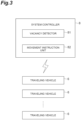
- the system controller 8 has a vacancy detector 81 and a movement instruction unit 82 as conceptual parts executing various kinds of control processing in the traveling vehicle system 1.
- the vacancy detector 81 and the movement instruction unit 82 formed as such conceptual parts can be configured as software in which a computer program stored in the ROM is loaded onto the RAM and executed by the CPU, for example.
- the system controller 8 manages the route R of the traveling vehicles 6 in a divided manner into the areas A1 to A3.
- the movement instruction unit 82 instructs the traveling vehicle 6 having the electricity storage amount (the battery remaining amount) of the electricity storage device 61 fallen below a first threshold (hereinafter also referred to as the "battery low traveling vehicle 6") to move to the charging point 7.
- a first threshold hereinafter also referred to as the "battery low traveling vehicle 6”
- each of the traveling vehicles 6 monitors the electricity storage amount of the electricity storage device 61 of its own vehicle and, if the electricity storage amount falls below the first threshold, requests charging from the system controller 8.
- the movement instruction unit 82 instructs the traveling vehicle 6 with a charging request to move to the charging point 7.
- the movement instruction unit 82 may monitor the electricity storage amount of each of the traveling vehicles 6 being regularly transmitted and may instruct the traveling vehicle 6 that has fallen below the first threshold to move to the charging point 7.
- the charging point 7 referred to in this example may be a vacant charging point 7A, in which a traveling vehicle 6 under charging is not present, or an in-use charging point 7B, in which a traveling vehicle 6 under charging is present.
- the traveling vehicle 6 having received a movement instruction moves to a certain charging point 7 contained in the movement instruction, and the electricity storage device 61 is charged at the charging point 7.
- the traveling vehicle 6 having been instructed to move to the in-use charging point 7B waits near the in-use charging point 7B until charging of an earlier traveling vehicle 6 is completed.
- the vacancy detector 81 detects a vacancy status of the charging point 7.
- the vacancy detector 81 detects the charging point 7 that is not charging a traveling vehicle 6 and is not designated as the movement destination of the movement instruction as the vacant charging point 7A.
- the presence or absence of vacancy in each of the charging points 7 can be monitored by managing the assignment status and the assignment completion status of the movement instructions to the charging points 7, a charging status in each of the charging points 7, and the like. Note that the presence or absence of vacancy in each of the charging points 7 can also be managed by providing a sensor or the like detecting the traveling vehicle 6 at each of the charging points 7.
- the vacancy detector 81 determines whether a specific charging point 70 (the charging point 7 hatched in FIG. 1 ) set in part of the charging points 7 is the vacant charging point 7A.
- the specific charging point 70 is set at least one of the charging points 7 disposed in each of the areas A1 to A3.
- one specific charging point 70 is set in the area A1 as one of the three areas set in the building 2
- two specific charging points 70 are set in the area A2
- one specific charging point 70 is set in the area A3.
- the vacancy detector 81 detects the vacancy status of half (50%) of the charging points 7 disposed in the building 2.
- the vacancy detector 81 detects the vacancy status of the specific charging points 70 set in each of the areas A1 to A3.
- the eight charging points 7 are arranged in one direction, and the specific charging points 70 are set so as not to be adjacent to each other. In other words, the specific charging points 70 are set every other charging point in the eight charging points 7. Note that "being set” referred to in this example refers to being stored as the specific charging points 70 by the system controller 8.
- the movement instruction unit 82 instructs the traveling vehicle 6 having the electricity storage amount equal to or above the first threshold to move to the charging point 7A. That is, the movement instruction unit 82, which normally moves the traveling vehicle 6 to the vacant charging point 7A when the electricity storage mount has fallen below the first threshold, moves the traveling vehicle 6 having the electricity storage amount equal to or above the first threshold to the vacant charging point 7A only when the vacant charging point 7A not charging the traveling vehicle 6 is detected by the vacancy detector 81.
- the movement instruction unit 82 provides an upper limit of the number of the traveling vehicles 6 instructed to move to the vacant charging point 7A.
- the upper limit of the number referred to in this example is a number obtained by summing the number of the traveling vehicles 6 having the electricity storage amount fallen below the first threshold (the battery low traveling vehicles 6) and the number of the traveling vehicles 6 having the electricity storage amount equal to or above the first threshold instructed to move to the vacant charging point 7A by the movement instruction unit 82.
- the movement instruction unit 82 does not instruct the traveling vehicles 6 having the electricity storage amount equal to or above the first threshold to move to the vacant charging point 7A.
- the movement instruction unit 82 of the present embodiment sets the upper limit of the number of the traveling vehicles 6 instructed to move to the vacant charging point 7A at three.
- the upper limit of the number is set by calculating how many traveling vehicles 6 or more becoming unable to travel at once due to charging causes an inability to satisfy a transport capacity level required for the traveling vehicle system 1 based on the thus calculated number.
- the movement instruction unit 82 instructs the traveling vehicle 6 having the smallest electricity storage amount among the traveling vehicles 6 having the electricity storage amount equal to or above the first threshold to move to the vacant charging point 7A. This preferentially charges the traveling vehicle 6 requiring charging in the near future and can thereby prevent that the traveling vehicle 6 falls below the first threshold.
- the movement instruction unit 82 may instruct the traveling vehicle 6 being at or above the first threshold and being at or below a second threshold (for example, 99.5% of the full electricity storage amount) lower than a full electricity storage amount to move to the vacant charging point 7A. In this case, overcharging of the electricity storage device 61 is prevented, and thus the electricity storage device 61 can be protected.
- the following describes an example of charging to the traveling vehicle 6 in the traveling vehicle system 1 using FIG. 4 .
- Charging in each of the traveling vehicles 6 is controlled by the system controller 8.
- the traveling vehicle controller 67 of each of the traveling vehicles 6 monitors the electricity storage amount of the electricity storage device 61 of its own vehicle and regularly transmits the electricity storage amount and its own position to the system controller 8.
- the system controller 8 monitors the electricity storage amount of the electricity storage device 61 of each of the traveling vehicles 6, the position of each of the traveling vehicles 6, the vacancy status of the charging points 7, and the completion status of the movement instruction.
- each of the traveling vehicles 6 transmits a charging request to the system controller 8.
- the system controller 8 monitors the presence or absence of the charging request from the traveling vehicle 6 (Step S1).
- the system controller 8 assigns a movement instruction to the charging point 7 to the traveling vehicle 6 with the charging request (Step S2).
- the system controller 8 assigns the movement instruction to the charging point 7 present at a position closest from the traveling vehicle 6 with the charging request among all the charging points 7.
- the system controller 8 may assign the movement instruction to the charging point 7 being currently vacant, the charging point 7 being present at a position closest to the traveling vehicle 6 that has requested charging.
- the system controller 8 searches for a vacant charging point 7A (Step S3). Specifically, the system controller 8 detects the presence or absence of a vacant charging point 7A, which is a charging point 7 that is not charging a traveling vehicle 6 and is not designated as the movement destination of a movement instruction that was issued to a traveling vehicle 6. More specifically, the system controller 8 detects whether there is a vacant charging point 7A among the four specific charging points 70. If detecting that there is no vacant charging point 7A among the four specific charging points 70 (S3: YES), the system controller 8 returns to Step S1 and monitors the occurrence of a battery low traveling vehicle 6.
- the system controller 8 determines whether a traveling vehicle 6 being at or above the first threshold and being at or below a third threshold (for example, 91% of the full electricity storage amount, hereinafter the "battery low candidate traveling vehicle 6"), which is an electricity storage amount less than the second threshold, is present (Step S4).
- a third threshold for example, 91% of the full electricity storage amount, hereinafter the "battery low candidate traveling vehicle 6"
- the system controller 8 of the present embodiment recognizes the charging point 7 neither charging a traveling vehicle 6 nor assigned with the movement instruction as the vacant charging point 7A.
- the third threshold can be calculated based on the viewpoint of becoming battery low before a certain time (X seconds) elapses from the current point in time.
- the certain time (X seconds) indicates an estimated time until the traveling vehicle 6 assigned with the movement instruction moves to the charging point 7 and charging is completed.
- the certain time (X seconds) can be, for example, 300 seconds.
- the discharge amount of the electricity storage device 61 can be calculated based on, for example, a distance the traveling vehicle 6 travels.
- the system controller 8 assigns a movement instruction to the vacant charging point 7A detected in Step S3 to the determined battery low candidate traveling vehicle 6 (Step S5).
- the system controller 8 assigns the movement instruction to the battery low candidate traveling vehicle 6 having the smallest electricity storage amount.
- the system controller 8 searches for a traveling vehicle 6 being neither battery low nor battery low candidate positioned closest to one charging point 7 searched for, that is, the traveling vehicle 6 having the electricity storage amount of greater than the third threshold and assigns a movement instruction to the vacant charging point 7A searched for in Step S3 to the traveling vehicle 6 searched for (Step S6).
- the traveling vehicle 6 having thus been assigned to the vacant charging point 7A is controlled to move to the vacant charging point 7A and is charged even if it is neither in the state of battery low nor in the state of battery low candidate.
- the searching for the battery low candidate traveling vehicle 6 in Step S4 and the traveling vehicle 6 being neither battery low nor battery low candidate in Step S6 may be narrowed to the traveling vehicle 6 traveling inside the area to which the vacant charging point 7A searched for belongs.
- Step S2 when the destination of the movement instruction is selected, all the charging points 7 are targeted, whereas in Step S5 and Step S6, when the destination of the movement instruction is selected, part (the specific charging points 70) of all the charging points 7 are targeted.
- the system controller 8 determines scheduled transport of articles (tasks) (Step S7). If determining that some tasks remain (S7: NO), the system controller 8 returns to Step S1 and again monitors the occurrence of a traveling vehicle 6 having a low battery. If determining that all the tasks have been digested (S7: YES), the system controller 8 ends the sequence of Step S1 to Step S6.
- the traveling vehicle system 1 of the above embodiment can move even the traveling vehicle 6 having the electricity storage amount not falling below the first threshold to the charging point 7 as soon as the charging point 7 becomes vacant and charge the traveling vehicle 6. This relatively increases the number of the traveling vehicles 6 in a state of a large electricity amount and can thus reduce the possibility of multiple traveling vehicles 6 falling below the first threshold occurring simultaneously.
- the vacancy detector 81 detects a charging point 7 that is not charging the traveling vehicle 6 and is not designated as the movement destination of the movement instruction as the vacant charging point 7A. This sets only a charging point 7 not being currently designated as the movement destination of the movement instruction among the currently vacant charging points 7 as the vacant charging point 7A and can thereby prevent that the number of the traveling vehicles 6 to be charged excessively increases. That is, the transport capacity of the traveling vehicle system 1 can be prevented to decrease.
- the vacancy detector 81 may determine whether the specific charging point 70 set in part of the charging points 7 is the vacant charging point 7A. This does not detect the vacant charging point 7A from among all the charging points 7 but detects the vacant charging point 7A from among partial charging points 7 (the specific charging points 70) and can thus prevent that the number of the traveling vehicles 6 to be charged excessively increases. That is, the transport capacity of the traveling vehicle system 1 can be prevented to decrease.
- the charging points 7 are disposed in each of the areas A1 to A3, and the specific charging point 70 is set in at least one of the charging points 7 disposed in each of the areas A1 to A3.
- the movement instruction to the vacant charging point 7A is assigned to the traveling vehicle 6 close to the vacant charging point 7A, but when there is a possibility that before the traveling vehicle 6 completes charging at the charging point 7, another traveling vehicle 6 will be battery low, the movement instruction to the vacant charging point 7A can be assigned to the traveling vehicle 6 having the smallest electricity storage amount among the possible traveling vehicles 6.
- the movement instruction unit 82 instructs the traveling vehicle 6 having a small electricity storage amount to move to the vacant charging point 7A in Step S4, but this is not limiting.
- the movement instruction unit 82 may instruct the traveling vehicle 6 closest to the vacant charging point 7A to move to the vacant charging point 7A in Step S4. Also in this case, by preferentially charging the traveling vehicle 6 close to the charging point 7, losses due to movement can be reduced. That is, the traveling vehicle 6 is quickly charged, and it can thus be prevented that a traveling vehicle 6 falls below the first threshold.
- the movement instruction unit 82 assigns the movement instruction to the traveling vehicle 6 closest to the specific charging point 70 in Step S6, but the movement instruction may be assigned to the traveling vehicle 6 having the smallest electricity storage amount from among the traveling vehicles 6 (having the electricity storage amount of greater than the third threshold).
- the movement instruction unit 82 may determine the presence or absence of a traveling vehicle 6 present within a certain distance from the specific charging point 70 and, if determining that there is such a traveling vehicle 6, assign the movement instruction to the traveling vehicle 6 having the smallest electricity storage amount or assign the movement instruction to the traveling vehicle 6 present closest to the specific charging point 70.
- the movement instruction unit 82 may determine the presence or absence of a traveling vehicle 6 being at or above the first threshold and being at or below the second threshold (for example, 99.5% of the full electricity storage amount) lower than the full electricity storage amount and may instruct such a traveling vehicle 6 to move to the vacant charging point 7A (Step S5). In this case, overcharging to the electricity storage device 61 is prevented, and thus the electricity storage device 61 can be protected.
- the above embodiment and modification have described an example in which eight charging points 7 are disposed, and four specific charging points 70 are set, but any change can be made as appropriate.
- the above embodiment and modification have described an example in which, in the divided three areas A1 to A3, the charging points 7 and the specific charging points 70 are set such that the number of the specific charging points 70 is smaller than the number of the charging points 7 in each of the areas, but the areas may be integrated into one area, and the charging points 7 and the specific charging points 70 may be set such that the number of the specific charging points 70 is smaller than the number of the charging points 7 in the one area.
- the setting and division of the areas can be set as appropriate in accordance with the area of the building 2 in which the traveling vehicle system 1 is installed or the like.
- the movement instruction unit 82 sets the upper limit of the number of the traveling vehicles 6 instructed to move to the vacant charging point 7A at three, but this is not limiting.
- the movement instruction unit 82 can change the upper limit of the number of the traveling vehicles 6 instructed to move to the vacant charging point 7A as appropriate so long as it is within a range of the number of the charging points 7 installed (or the number of the specific charging points 70 installed), and in the above embodiment, the upper limit of the traveling vehicles 6 instructed to move to the vacant charging point 7A can be set at one to four.
- the vacancy detector 81 searches the specific charging points 70 set in advance for the vacant charging point 7A but may search all the charging points 7 for the vacant charging point 7A without setting any specific charging point 70.
- the traveling vehicle 6 is a trackless traveling vehicle traveling on the floor of the building 2 but it may be a tracked traveling vehicle traveling on a track such as a rail having branching and confluence.
Landscapes
- Engineering & Computer Science (AREA)
- Power Engineering (AREA)
- Transportation (AREA)
- Mechanical Engineering (AREA)
- Charge And Discharge Circuits For Batteries Or The Like (AREA)
Abstract
A traveling vehicle system includes a plurality of traveling vehicles having an electricity storage device and a travel driving unit driven by electric power stored in the electricity storage device and configured to travel on a route set in advance, a plurality of charging points provided along the route and configured to charge the electricity storage device of the traveling vehicles, and a controller configured to instruct a traveling vehicle having an electricity storage amount of the electricity storage device fallen below a first threshold to move to the charging point. The controller has a vacancy detector configured to detect a vacancy status of the charging points for the traveling vehicles, and a movement instruction unit configured to, instruct the traveling vehicle having the electricity storage amount equal to or above the first threshold to move to the vacant charging point, when a vacant charging point not charging a traveling vehicle is detected by the vacancy detector.
Description
- An aspect of the present invention relates to a traveling vehicle system.
- A traveling vehicle system (a transport vehicle system) including unmanned traveling vehicles traveling by the electric power of an electricity storage device is known (for example, Patent Literature 1). In the traveling vehicle system, the traveling vehicles travel on a certain traveling route based on instructions from a superordinate controller or the like to transport articles such as baggage. The traveling vehicles are controlled by the superordinate controller so as to move to charging points when they fall below a certain electricity storage amount so that the electricity storage amount does not become zero.
- [Patent Literature 1]
Japanese Unexamined Patent Publication No. 2019-101963 - However, in the traveling vehicles constituting the traveling vehicle system, when many traveling vehicles fall below the certain electricity storage amount at the same time and head for the charging points at the same time, the number of operable traveling vehicles temporarily decreases, and the transport capacity of the traveling vehicle system decreases.
- Thus, an object of an aspect of the present invention is to provide a traveling vehicle system capable of reducing the possibility of multiple traveling vehicles having a decreased electricity storage amount occurring simultaneously.
- A traveling vehicle according to an aspect of the present invention includes a plurality of traveling vehicles having an electricity storage device and a travel driving unit driven by electric power stored in the electricity storage device and configured to travel on a route set in advance, a plurality of charging points provided along the route and configured to charge the electricity storage device of the traveling vehicles, and a controller configured to instruct a traveling vehicle having an electricity storage amount of the electricity storage device fallen below a first threshold to move to a charging point, the controller having a vacancy detector configured to detect a vacancy status of the charging points for the traveling vehicles, and a movement instruction unit configured to instruct a traveling vehicle having the electricity storage amount equal or above the first threshold or more to move to the vacant charging point, when a vacant charging point not charging a traveling vehicle is detected by the vacancy detector.
- The traveling vehicle system of this configuration can even move the traveling vehicle having the electricity storage amount not falling below the first threshold to the charging point as soon as the charging point becomes vacant and charge the traveling vehicle. This relatively increases the number of the traveling vehicles in a state of a large electricity storage amount and can thus reduce the possibility of multiple travelling vehicles falling below the first threshold occurring simultaneously.
- In the traveling vehicle system according to an aspect of the present invention, the vacancy detector may detect the charging point that is not charging a traveling vehicle and is not designated as a movement destination of the movement instruction as the vacant charging point. This configuration sets only the charging point not being currently designated as the movement destination of the movement instruction among the currently vacant charging points the vacant charging point and can thereby inhibit the number of the traveling vehicles to be charged from excessively increasing. That is, the transport capacity of the traveling vehicle system can be prevented to decrease.
- In the traveling vehicle system according to an aspect of the present invention, the vacancy detector may determine whether a specific charging point set in part of the charging points is the vacant charging point. This configuration does not detect the vacant charging point from among all the charging points but detects the vacant charging point from among partial charging points and can thus prevent that the number of the traveling vehicles to be charged excessively increases. That is, the transport capacity of the traveling vehicle system can be prevented to decrease.
- In the traveling vehicle system according to an aspect of the present invention, the controller may manage the route of the traveling vehicles in a divided manner into a plurality of areas, the charging points may be disposed in the respective areas, and the specific charging point may be set in at least one of the charging points disposed in each of the areas. This configuration sets the specific charging points such that they are not concentrated in a certain area and can thus prevent that the number of the traveling vehicles under charging to locally increases. This enables quick charging of a traveling vehicle having the electricity storage amount fallen below the first threshold.
- In the traveling vehicle system according to an aspect of the present invention, the movement instruction unit may provide an upper limit of the number of the traveling vehicles instructed to move to the vacant charging point. This configuration can prevent that the number of the travelling vehicles to be charged excessively increases.
- In the traveling vehicle system according to an aspect of the present invention, the movement instruction unit may instruct the traveling vehicle being at or above the first threshold and being at or below a second threshold lower than a full electricity storage amount to move to the vacant charging point. This configuration prevents overcharging to the electricity storage device and can thus protect the electricity storage device.
- In the traveling vehicle system according to an aspect of the present invention, the movement instruction unit may instruct the traveling vehicle having the smallest electricity storage amount among the traveling vehicles having the electricity storage amount at or above the first threshold and at or below the second threshold to move to the vacant charging point. This configuration preferentially charges the traveling vehicle requiring charging in the near future and can thereby prevent that a traveling vehicle falls below the first threshold.
- In the traveling vehicle system according to an aspect of the present invention, the movement instruction unit may instruct the traveling vehicle positioned within a certain zone from the vacant charging point to move to the vacant charging point. This configuration preferentially charges the traveling vehicle close to the charging point and can thereby reduce losses due to movement. That is, the traveling vehicle is quickly charged, and can thus prevent that the traveling vehicle falls below the first threshold.
- In the traveling vehicle system according to an aspect of the present invention, the movement instruction unit may instruct the traveling vehicle positioned closest to the vacant charging point to move to the vacant charging point. This configuration preferentially charges the traveling vehicle closest to the charging point, thereby quickly charges the traveling vehicle while minimizing losses due to movement, and can thus prevent more effectively that the traveling vehicle falls below the first threshold.
- An aspect of the present invention can reduce the possibility of multiple traveling vehicles having a decreased electricity storage amount occurring simultaneously.
-
- [
FIG. 1] FIG. 1 is an overall schematic diagram of a traveling vehicle system according to an embodiment. - [
FIG. 2] FIG. 2 is a schematic configuration diagram of a traveling vehicle. - [
FIG. 3] FIG. 3 is a functional block diagram illustrating a functional configuration of the traveling vehicle system according to the embodiment. - [
FIG. 4] FIG. 4 is a flowchart illustrating movement control of the traveling vehicle by a movement instruction unit. - The following describes a
traveling vehicle system 1 according to an embodiment with reference to the accompanying drawings. In the description of the drawings, the same elements are denoted by the same symbols, and redundant descriptions are omitted. - As illustrated in
FIG. 1 , thetraveling vehicle system 1 is, for example, a transport system performing transport of articles betweenautomated warehouses 3 and various kinds ofprocessing apparatuses 4 disposed in abuilding 2 of a factory manufacturing secondary batteries, transport of articles between the outside and inside of thebuilding 2, and the like. Thetraveling vehicle system 1 includes a plurality oftraveling vehicles 6,charging points 7, and a system controller 8 (refer toFIG. 3 ). - The
automated warehouse 3 is a warehouse storing a plurality of articles. Theautomated warehouse 3 has storage shelves (not illustrated) capable of placing a plurality of articles, a stacker crane (not illustrated) transporting articles between the storage shelves and incoming andoutgoing ports 3A, and the incoming andoutgoing ports 3A to which articles can be transferred by thetraveling vehicles 6. The various kinds ofprocessing apparatuses 4 are disposed such that articles can be transferred thereto by thetraveling vehicles 6. Examples of the various kinds ofprocessing apparatuses 4 include electrode manufacturing apparatuses and cell assembly apparatuses. - As illustrated in
FIG. 1 andFIG. 2 , thetraveling vehicle 6, supplied with electric power from anelectricity storage device 61, autonomously travels along a route R set in advance. Thetraveling vehicle 6 is, for example, an automated guided vehicle (AGV). The route R set in advance may be, for example, a magnetic tape or a magnetic marker provided so as to form a traveling route for thetraveling vehicle 6 on the floor of thebuilding 2. In this case, thetraveling vehicle 6 travels while detecting a magnetic signal or the like output from the magnetic tape, the magnetic marker, or the like. Note that thetraveling vehicle 6 may travel while detecting its own position by generating light from a laser or the like and detecting reflected light reflected by a mirror mounted on a wall or the like of thebuilding 2 or travel while detecting its own position by utilizing information on GPS or the like. - The
traveling vehicle system 1 of the present embodiment arranges a plurality oftraveling vehicles 6. Each of thetraveling vehicles 6 mainly has theelectricity storage device 61, anelectricity receiving unit 62, atravel driving unit 63, a pair ofwheels communication interface 65, and atraveling vehicle controller 67. - The
electricity storage device 61 supplies electric power to thetravel driving unit 63, thetraveling vehicle controller 67, and the like. Theelectricity storage device 61 is a secondary battery capable of being charged with external electric power. Examples of theelectricity storage device 61 include nickel-cadmium batteries, nickel-hydrogen batteries, and lithium-ion batteries. - The electricity receiving
unit 62 is provided at the front or rear of the traveling direction of thetraveling vehicle 6. The electricity receivingunit 62 of the present embodiment is provided at the rear of the traveling direction. The electricity receivingunit 62 is an electricity receiving coil converting an alternating magnetic field output from thecharging point 7 and supplying the electric power to theelectricity storage device 61 as charging electric power. Note that when thecharging point 7 is a charging device of a contact power supply system, theelectricity receiving unit 62 is an electricity receiving electrode capable of being in contact with a power supply electrode of thecharging point 7. - The
travel driving unit 63 is driven by the electric power stored in theelectricity storage device 61. Thetravel driving unit 63 is, for example, a motor. Thetravel driving unit 63 is controlled by the travelingvehicle controller 67. The pair ofwheels travel driving unit 63 to cause the travelingvehicle 6 to travel. - The
communication interface 65 is provided at a certain position of the travelingvehicle 6 and is a wireless communication device for communicating with thesystem controller 8. Thecommunication interface 65 is, for example, a wireless LAN device. The travelingvehicle controller 67 receives various kinds of instructions from thesystem controller 8 via thecommunication interface 65 and controls the travelingvehicle 6 based on the received instructions. - The traveling
vehicle controller 67 is a computer system having a central processing unit (CPU), storage devices such as a random access memory (RAM), a read only memory (ROM), and a solid state drive (SSD), various kinds of interfaces (for example, a network interface, an A/D convertor, and a D/A convertor), and the like. Part or the whole of the functions of the travelingvehicle controller 67 described below may be stored in the storage devices and implemented by a computer program capable of being executed by the computer system. Part or the whole of the functions of the travelingvehicle controller 67 may be implemented by hardware such as a system on a chip (SoC). - The traveling
vehicle controller 67 controls the units constituting the travelingvehicle 6. Specifically, the travelingvehicle controller 67 moves the travelingvehicle 6 based on a movement instruction transmitted by thesystem controller 8. That is, the travelingvehicle controller 67 drives thetravel driving unit 63 to move the travelingvehicle 6 to a destination contained in the movement instruction. Examples of the destination designated by thesystem controller 8 include a certain incoming andoutgoing port 3A of theautomated warehouse 3, acertain processing apparatus 4, and acertain charging point 7. Upon reaching the destination contained in the movement instruction, the travelingvehicle controller 67 provides notification that the movement instruction has been completed to thesystem controller 8. - The traveling
vehicle controller 67 calculates a battery remaining amount of theelectricity storage device 61 mounted on its own vehicle. The travelingvehicle controller 67, for example, regularly calculates a current electricity storage amount of theelectricity storage device 61 based on the voltage of theelectricity storage device 61 input via an A/D convertor or the like. The travelingvehicle controller 67 provides notification of the current electricity storage amount of theelectricity storage device 61 regularly calculated to thesystem controller 8. This enables thesystem controller 8 to monitor the current electricity storage amount of the electricity storage device included in each of the travelingvehicles 6. - The
charging point 7 charges theelectricity storage device 61 of the travelingvehicle 6 stopped at a certain position with respect to thecharging point 7. The charging points 7 are provided along the route R. In the present embodiment, eightcharging points 7 are installed inside thebuilding 2. More specifically, twocharging points 7 are disposed in an area A1 as one of three areas set in thebuilding 2, fourcharging points 7 are disposed in an area A2, and twocharging points 7 are disposed in an area A3. Note that described is an example in which a plurality of chargingpoints 7 are disposed in each of the areas A1 to A3, but only onecharging point 7 may be disposed in some areas. Thecharging point 7 outputs charging electric power to theelectricity receiving unit 62 of the travelingvehicle 6 to execute charging of theelectricity storage device 61. Thecharging point 7 is, for example, a charging device of a non-contact power supply system having a power supply coil outputting an alternating magnetic field as the charging electric power. Note that thecharging point 7 is not limited to the charging device of the wireless power supply system and may be, for example, a charging device of a contact power supply system being in contact with an electricity receiving electrode (not illustrated) included in the travelingvehicle 6 to output charging electric power to the electricity receiving electrode. - As described above, the three areas A1 to A3 are set in the
building 2. The areas A1 to A3 referred to in this example may be areas set by, for example, virtually dividing the area in which the route R of the travelingvehicles 6 is disposed, may be areas set for respective manufacturing steps, or may be set for respective spaces physically sectioned. These areas A1 to A3 are managed by thesystem controller 8. - The
system controller 8 controls the travel of the travelingvehicles 6. Thesystem controller 8 is a computer system having a CPU, storage devices such as a RAM, a ROM, and an SSD, various kinds of interfaces (for example, a network interface, an A/D convertor, and a D/A convertor), and the like. Part or the whole of the functions of thesystem controller 8 described below may be stored in the storage devices and implemented by a computer program capable of being executed by the computer system. Part or the whole of the functions of thesystem controller 8 may be implemented by hardware such as a system on a chip (SoC). Thesystem controller 8 is provided to be able to communicate via therespective communication interface 65 with the travellingvehicle controller 67 of each of the travelingvehicles 6. - As illustrated in
FIG. 3 , thesystem controller 8 has avacancy detector 81 and amovement instruction unit 82 as conceptual parts executing various kinds of control processing in the travelingvehicle system 1. Thevacancy detector 81 and themovement instruction unit 82 formed as such conceptual parts can be configured as software in which a computer program stored in the ROM is loaded onto the RAM and executed by the CPU, for example. Thesystem controller 8 manages the route R of the travelingvehicles 6 in a divided manner into the areas A1 to A3. - The
movement instruction unit 82 instructs the travelingvehicle 6 having the electricity storage amount (the battery remaining amount) of theelectricity storage device 61 fallen below a first threshold (hereinafter also referred to as the "battery low travelingvehicle 6") to move to thecharging point 7. Specifically, each of the travelingvehicles 6 monitors the electricity storage amount of theelectricity storage device 61 of its own vehicle and, if the electricity storage amount falls below the first threshold, requests charging from thesystem controller 8. Themovement instruction unit 82 instructs the travelingvehicle 6 with a charging request to move to thecharging point 7. Note that themovement instruction unit 82 may monitor the electricity storage amount of each of the travelingvehicles 6 being regularly transmitted and may instruct the travelingvehicle 6 that has fallen below the first threshold to move to thecharging point 7. Note that thecharging point 7 referred to in this example may be avacant charging point 7A, in which a travelingvehicle 6 under charging is not present, or an in-use charging point 7B, in which a travelingvehicle 6 under charging is present. The travelingvehicle 6 having received a movement instruction moves to acertain charging point 7 contained in the movement instruction, and theelectricity storage device 61 is charged at thecharging point 7. The travelingvehicle 6 having been instructed to move to the in-use charging point 7B waits near the in-use charging point 7B until charging of anearlier traveling vehicle 6 is completed. - The
vacancy detector 81 detects a vacancy status of thecharging point 7. Thevacancy detector 81 detects thecharging point 7 that is not charging a travelingvehicle 6 and is not designated as the movement destination of the movement instruction as thevacant charging point 7A. The presence or absence of vacancy in each of the charging points 7 can be monitored by managing the assignment status and the assignment completion status of the movement instructions to the charging points 7, a charging status in each of the charging points 7, and the like. Note that the presence or absence of vacancy in each of the charging points 7 can also be managed by providing a sensor or the like detecting the travelingvehicle 6 at each of the charging points 7. Furthermore, thevacancy detector 81 determines whether a specific charging point 70 (thecharging point 7 hatched inFIG. 1 ) set in part of the charging points 7 is thevacant charging point 7A. - Specifically, as illustrated in
FIG. 1 , fourcharging points 7 out of the eightcharging points 7 are set as the specific charging points 70. Thespecific charging point 70 is set at least one of the charging points 7 disposed in each of the areas A1 to A3. In the present embodiment, onespecific charging point 70 is set in the area A1 as one of the three areas set in thebuilding 2, two specific charging points 70 are set in the area A2, and onespecific charging point 70 is set in the area A3. In other words, in the present embodiment, thevacancy detector 81 detects the vacancy status of half (50%) of the charging points 7 disposed in thebuilding 2. Thevacancy detector 81 detects the vacancy status of the specific charging points 70 set in each of the areas A1 to A3. - The eight
charging points 7 are arranged in one direction, and the specific charging points 70 are set so as not to be adjacent to each other. In other words, the specific charging points 70 are set every other charging point in the eight charging points 7. Note that "being set" referred to in this example refers to being stored as the specific charging points 70 by thesystem controller 8. - When the
vacant charging point 7A (7) not charging the travelingvehicle 6 is detected by thevacancy detector 81, themovement instruction unit 82 instructs the travelingvehicle 6 having the electricity storage amount equal to or above the first threshold to move to thecharging point 7A. That is, themovement instruction unit 82, which normally moves the travelingvehicle 6 to thevacant charging point 7A when the electricity storage mount has fallen below the first threshold, moves the travelingvehicle 6 having the electricity storage amount equal to or above the first threshold to thevacant charging point 7A only when thevacant charging point 7A not charging the travelingvehicle 6 is detected by thevacancy detector 81. - Furthermore, the
movement instruction unit 82 provides an upper limit of the number of the travelingvehicles 6 instructed to move to thevacant charging point 7A. The upper limit of the number referred to in this example is a number obtained by summing the number of the travelingvehicles 6 having the electricity storage amount fallen below the first threshold (the battery low traveling vehicles 6) and the number of the travelingvehicles 6 having the electricity storage amount equal to or above the first threshold instructed to move to thevacant charging point 7A by themovement instruction unit 82. For example, when the upper limit is reached by the battery low travelingvehicles 6 alone, themovement instruction unit 82 does not instruct the travelingvehicles 6 having the electricity storage amount equal to or above the first threshold to move to thevacant charging point 7A. - For example, the
movement instruction unit 82 of the present embodiment sets the upper limit of the number of the travelingvehicles 6 instructed to move to thevacant charging point 7A at three. In the present embodiment, there is a possibility that a maximum of four vacant charging points 7A will be detected, but even in that case, only three travelingvehicles 6 can be moved to the vacant charging points 7A. This can prevent the number of the travelingvehicles 6 to be charged from excessively increasing. The upper limit of the number is set by calculating how many travelingvehicles 6 or more becoming unable to travel at once due to charging causes an inability to satisfy a transport capacity level required for the travelingvehicle system 1 based on the thus calculated number. - Note that without setting the specific charging points in the charging points, only the upper limit of the number described above may be set. Also in these cases, operation not falling below the transport capacity level required for the traveling
vehicle system 1 is possible. - When the
vacant charging point 7A is detected by thevacancy detector 81, themovement instruction unit 82 instructs the travelingvehicle 6 having the smallest electricity storage amount among the travelingvehicles 6 having the electricity storage amount equal to or above the first threshold to move to thevacant charging point 7A. This preferentially charges the travelingvehicle 6 requiring charging in the near future and can thereby prevent that the travelingvehicle 6 falls below the first threshold. Note that themovement instruction unit 82 may instruct the travelingvehicle 6 being at or above the first threshold and being at or below a second threshold (for example, 99.5% of the full electricity storage amount) lower than a full electricity storage amount to move to thevacant charging point 7A. In this case, overcharging of theelectricity storage device 61 is prevented, and thus theelectricity storage device 61 can be protected. - The following describes an example of charging to the traveling
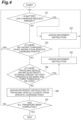
vehicle 6 in the travelingvehicle system 1 usingFIG. 4 . Charging in each of the travelingvehicles 6 is controlled by thesystem controller 8. As described above, the travelingvehicle controller 67 of each of the travelingvehicles 6 monitors the electricity storage amount of theelectricity storage device 61 of its own vehicle and regularly transmits the electricity storage amount and its own position to thesystem controller 8. Thesystem controller 8 monitors the electricity storage amount of theelectricity storage device 61 of each of the travelingvehicles 6, the position of each of the travelingvehicles 6, the vacancy status of the charging points 7, and the completion status of the movement instruction. - When detecting that the electricity storage amount of the
electricity storage device 61 has fallen below the first threshold (for example, 90% of the full electricity storage amount, hereinafter also referred to as "having become battery low"), each of the travelingvehicles 6 transmits a charging request to thesystem controller 8. Thesystem controller 8 monitors the presence or absence of the charging request from the traveling vehicle 6 (Step S1). Upon reception of the charging request from the traveling vehicle 6 (S1: YES), thesystem controller 8 assigns a movement instruction to thecharging point 7 to the travelingvehicle 6 with the charging request (Step S2). Thesystem controller 8 assigns the movement instruction to thecharging point 7 present at a position closest from the travelingvehicle 6 with the charging request among all the charging points 7. At this time, thesystem controller 8 may assign the movement instruction to thecharging point 7 being currently vacant, thecharging point 7 being present at a position closest to the travelingvehicle 6 that has requested charging. - If having not received the charging request from a traveling
vehicle 6, that is, a travelingvehicle 6 whose battery is currently low (hereinafter also referred to as the "battery low travelingvehicle 6") is not present (S1: NO), thesystem controller 8 searches for avacant charging point 7A (Step S3). Specifically, thesystem controller 8 detects the presence or absence of avacant charging point 7A, which is acharging point 7 that is not charging a travelingvehicle 6 and is not designated as the movement destination of a movement instruction that was issued to a travelingvehicle 6. More specifically, thesystem controller 8 detects whether there is avacant charging point 7A among the four specific charging points 70. If detecting that there is novacant charging point 7A among the four specific charging points 70 (S3: YES), thesystem controller 8 returns to Step S1 and monitors the occurrence of a batterylow traveling vehicle 6. - If detecting that there is a
vacant charging point 7A among the four specific charging points 70 (S3: NO), thesystem controller 8 determines whether a travelingvehicle 6 being at or above the first threshold and being at or below a third threshold (for example, 91% of the full electricity storage amount, hereinafter the "battery lowcandidate traveling vehicle 6"), which is an electricity storage amount less than the second threshold, is present (Step S4). Note that thesystem controller 8 of the present embodiment recognizes thecharging point 7 neither charging a travelingvehicle 6 nor assigned with the movement instruction as thevacant charging point 7A. The third threshold can be calculated based on the viewpoint of becoming battery low before a certain time (X seconds) elapses from the current point in time. The certain time (X seconds) indicates an estimated time until the travelingvehicle 6 assigned with the movement instruction moves to thecharging point 7 and charging is completed. The certain time (X seconds) can be, for example, 300 seconds. The discharge amount of theelectricity storage device 61 can be calculated based on, for example, a distance the travelingvehicle 6 travels. - If determining that there is a battery low candidate traveling vehicle 6 (S4: YES), the
system controller 8 assigns a movement instruction to thevacant charging point 7A detected in Step S3 to the determined battery low candidate traveling vehicle 6 (Step S5). When a plurality of the battery lowcandidate traveling vehicles 6 are searched for, thesystem controller 8 assigns the movement instruction to the battery lowcandidate traveling vehicle 6 having the smallest electricity storage amount. - If determining that there is no battery low candidate traveling vehicle 6 (S4: NO), the
system controller 8 searches for a travelingvehicle 6 being neither battery low nor battery low candidate positioned closest to onecharging point 7 searched for, that is, the travelingvehicle 6 having the electricity storage amount of greater than the third threshold and assigns a movement instruction to thevacant charging point 7A searched for in Step S3 to the travelingvehicle 6 searched for (Step S6). The travelingvehicle 6 having thus been assigned to thevacant charging point 7A is controlled to move to thevacant charging point 7A and is charged even if it is neither in the state of battery low nor in the state of battery low candidate. Note that the searching for the battery lowcandidate traveling vehicle 6 in Step S4 and the travelingvehicle 6 being neither battery low nor battery low candidate in Step S6 may be narrowed to the travelingvehicle 6 traveling inside the area to which thevacant charging point 7A searched for belongs. - The assignment of the movement instruction in Step S2 and the assignment of the movement instruction in Step S5 and Step S6 are different in the following point. In Step S2, when the destination of the movement instruction is selected, all the charging points 7 are targeted, whereas in Step S5 and Step S6, when the destination of the movement instruction is selected, part (the specific charging points 70) of all the charging points 7 are targeted.
- The
system controller 8 determines scheduled transport of articles (tasks) (Step S7). If determining that some tasks remain (S7: NO), thesystem controller 8 returns to Step S1 and again monitors the occurrence of a travelingvehicle 6 having a low battery. If determining that all the tasks have been digested (S7: YES), thesystem controller 8 ends the sequence of Step S1 to Step S6. - The following describes the effects of the traveling
vehicle system 1 of the above embodiment. The travelingvehicle system 1 of the above embodiment can move even the travelingvehicle 6 having the electricity storage amount not falling below the first threshold to thecharging point 7 as soon as thecharging point 7 becomes vacant and charge the travelingvehicle 6. This relatively increases the number of the travelingvehicles 6 in a state of a large electricity amount and can thus reduce the possibility of multiple travelingvehicles 6 falling below the first threshold occurring simultaneously. - In the traveling
vehicle system 1 of the above embodiment, thevacancy detector 81 detects acharging point 7 that is not charging the travelingvehicle 6 and is not designated as the movement destination of the movement instruction as thevacant charging point 7A. This sets only acharging point 7 not being currently designated as the movement destination of the movement instruction among the currentlyvacant charging points 7 as thevacant charging point 7A and can thereby prevent that the number of the travelingvehicles 6 to be charged excessively increases. That is, the transport capacity of the travelingvehicle system 1 can be prevented to decrease. - In the traveling
vehicle system 1 of the above embodiment, thevacancy detector 81 may determine whether thespecific charging point 70 set in part of the charging points 7 is thevacant charging point 7A. This does not detect thevacant charging point 7A from among all the charging points 7 but detects thevacant charging point 7A from among partial charging points 7 (the specific charging points 70) and can thus prevent that the number of the travelingvehicles 6 to be charged excessively increases. That is, the transport capacity of the travelingvehicle system 1 can be prevented to decrease. - In the traveling
vehicle system 1 of the above embodiment, the charging points 7 are disposed in each of the areas A1 to A3, and thespecific charging point 70 is set in at least one of the charging points 7 disposed in each of the areas A1 to A3. This sets the specific charging points 70 such that they are not concentrated in a certain area and can thus prevent that the number of the travelingvehicles 6 under charging locally increases. That is, by moving the travelingvehicle 6 having the electricity storage amount fallen below the first threshold while avoiding that the charging points 7 under charging are locally increased in number, it can be prevented that the distance to move to thecharging point 7 enabling charging becomes long. This enables quick charging of a travelingvehicle 6 having the electricity storage amount fallen below the first threshold. - In the traveling
vehicle system 1 of the above embodiment, basically, the movement instruction to thevacant charging point 7A is assigned to the travelingvehicle 6 close to thevacant charging point 7A, but when there is a possibility that before the travelingvehicle 6 completes charging at thecharging point 7, another travelingvehicle 6 will be battery low, the movement instruction to thevacant charging point 7A can be assigned to the travelingvehicle 6 having the smallest electricity storage amount among the possible travelingvehicles 6. - Although one embodiment has been described, an aspect of the present invention is not limited to the above embodiment. Various changes can be made without departing from the gist of the invention.
- The above embodiment and modification have described an example in which when the
vacant charging point 7A is detected by thevacancy detector 81, themovement instruction unit 82 instructs the travelingvehicle 6 having a small electricity storage amount to move to thevacant charging point 7A in Step S4, but this is not limiting. For example, instead of the above control, when thevacant charging point 7A is detected by thevacancy detector 81, themovement instruction unit 82 may instruct the travelingvehicle 6 closest to thevacant charging point 7A to move to thevacant charging point 7A in Step S4. Also in this case, by preferentially charging the travelingvehicle 6 close to thecharging point 7, losses due to movement can be reduced. That is, the travelingvehicle 6 is quickly charged, and it can thus be prevented that a travelingvehicle 6 falls below the first threshold. - The above embodiment and modification have described an example in which the
movement instruction unit 82 assigns the movement instruction to the travelingvehicle 6 closest to thespecific charging point 70 in Step S6, but the movement instruction may be assigned to the travelingvehicle 6 having the smallest electricity storage amount from among the traveling vehicles 6 (having the electricity storage amount of greater than the third threshold). - The above embodiment and modification have described an example in which when the
vacant charging point 7A is detected by thevacancy detector 81, the presence or absence of the traveling vehicle having the electricity storage amount equal to or above the first threshold and equal to or below the third threshold is determined (Step S4), but this is not limiting. For example, when thevacant charging point 7A is detected by thevacancy detector 81, themovement instruction unit 82 may determine the presence or absence of a travelingvehicle 6 present within a certain distance from thespecific charging point 70 and, if determining that there is such a travelingvehicle 6, assign the movement instruction to the travelingvehicle 6 having the smallest electricity storage amount or assign the movement instruction to the travelingvehicle 6 present closest to thespecific charging point 70. - The above embodiment and modification have described an example in which when the
vacant charging point 7A is detected by thevacancy detector 81, the presence or absence of a traveling vehicle having the electricity storage amount equal to or above the first threshold and equal to or below the third threshold is determined (Step S4), but this is not limiting. For example, themovement instruction unit 82 may determine the presence or absence of a travelingvehicle 6 being at or above the first threshold and being at or below the second threshold (for example, 99.5% of the full electricity storage amount) lower than the full electricity storage amount and may instruct such a travelingvehicle 6 to move to thevacant charging point 7A (Step S5). In this case, overcharging to theelectricity storage device 61 is prevented, and thus theelectricity storage device 61 can be protected. - The above embodiment and modification have described an example in which eight
charging points 7 are disposed, and four specific charging points 70 are set, but any change can be made as appropriate. In addition, the above embodiment and modification have described an example in which, in the divided three areas A1 to A3, the charging points 7 and the specific charging points 70 are set such that the number of the specific charging points 70 is smaller than the number of the charging points 7 in each of the areas, but the areas may be integrated into one area, and the charging points 7 and the specific charging points 70 may be set such that the number of the specific charging points 70 is smaller than the number of the charging points 7 in the one area. The setting and division of the areas can be set as appropriate in accordance with the area of thebuilding 2 in which the travelingvehicle system 1 is installed or the like. - In the above embodiment and modification, the
movement instruction unit 82 sets the upper limit of the number of the travelingvehicles 6 instructed to move to thevacant charging point 7A at three, but this is not limiting. For example, themovement instruction unit 82 can change the upper limit of the number of the travelingvehicles 6 instructed to move to thevacant charging point 7A as appropriate so long as it is within a range of the number of the charging points 7 installed (or the number of the specific charging points 70 installed), and in the above embodiment, the upper limit of the travelingvehicles 6 instructed to move to thevacant charging point 7A can be set at one to four. - The above embodiment and modification have described an example in which the
vacancy detector 81 searches the specific charging points 70 set in advance for thevacant charging point 7A but may search all the charging points 7 for thevacant charging point 7A without setting anyspecific charging point 70. - The above embodiment and modification have described an example in which the traveling
vehicle 6 is a trackless traveling vehicle traveling on the floor of thebuilding 2 but it may be a tracked traveling vehicle traveling on a track such as a rail having branching and confluence. - The technical subject of aspects of the present invention can be described as follows:
- [1] A traveling vehicle system including:
- a plurality of traveling vehicles having an electricity storage device and a travel driving unit driven by electric power stored in the electricity storage device and configured to travel on a route set in advance;
- a plurality of charging points provided along the route and configured to charge the electricity storage device of the traveling vehicles; and
- a controller configured to instruct a traveling vehicle having an electricity storage amount of the electricity storage device fallen below a first threshold to move to a charging point,
- the controller having:
- a vacancy detector configured to detect a vacancy status of the charging points for the traveling vehicles; and
- a movement instruction unit configured to instruct a traveling vehicle having the electricity storage amount equal to or above the first threshold to move to the vacant charging point, when a vacant charging point not charging a traveling vehicle is detected by the vacancy detector.
- [2] The traveling vehicle system according to [1], in which the vacancy detector detects the charging point that is not charging a traveling vehicle and is not designated as a movement destination of the movement instruction as the vacant charging point.
- [3] The traveling vehicle system according to [1] or [2], in which the vacancy detector determines whether a specific charging point set in part of the charging points is the vacant charging point.
- [4] The traveling vehicle system according to [3], in which
- the controller manages the route of the traveling vehicles in a divided manner into a plurality of areas,
- the charging points are disposed in each of the areas, and
- the specific charging point is set in at least one of the charging points disposed in each of the areas.
- [5] The traveling vehicle system according to any one of [1] to [4], in which the movement instruction unit provides an upper limit of a number of the traveling vehicles instructed to move to the vacant charging point.
- [6] The traveling vehicle system according to any one of [1] to [5], in which the movement instruction unit instructs the traveling vehicle being at or above the first threshold and being at or below a second threshold lower than a full electricity storage amount to move to the vacant charging point.
- [7] The traveling vehicle system according to [6], in which the movement instruction unit instructs the traveling vehicle having the smallest electricity storage amount among the traveling vehicles having the electricity storage amount equal to or above the first threshold and equal to or below the second threshold to move to the vacant charging point.
- [8] The traveling vehicle system according to any one of [1] to [7], in which the movement instruction unit instructs the traveling vehicle positioned within a certain zone from the vacant charging point to move to the vacant charging point.
- [9] The traveling vehicle system according to [8], in which the movement instruction unit instructs the traveling vehicle positioned closest to the vacant charging point to move to the vacant charging point.
-
- 1 Traveling vehicle system
- 2 Building
- 3 Automated warehouse
- 4 Processing apparatus
- 6 Traveling vehicle
- 7 Charging point
- 7A Vacant charging point
- 7B In-use charging point
- 8 System controller (controller)
- 61 Electricity storage device
- 62 Electricity receiving unit
- 63 Travel driving unit
- 67 Traveling vehicle controller
- 70 Specific charging point
- 81 Vacancy detector
- 82 Movement instruction unit
- R Route
Claims (9)
- A traveling vehicle system including:a plurality of traveling vehicles having an electricity storage device and a travel driving unit driven by electric power stored in the electricity storage device and configured to travel on a route set in advance;a plurality of charging points provided along the route and configured to charge the electricity storage device of the traveling vehicles; anda controller configured to instruct a traveling vehicle having an electricity storage amount of the electricity storage device fallen below a first threshold to move to a charging point,the controller having:a vacancy detector configured to detect a vacancy status of the charging points for the traveling vehicles; anda movement instruction unit configured to instruct a traveling vehicle having the electricity storage amount of the first threshold or more to move to the vacant charging point, when a vacant charging point not charging a traveling vehicle is detected by the vacancy detector.
- The traveling vehicle system according to claim 1, wherein the vacancy detector detects the charging point that is not charging a traveling vehicle and is not designated as a movement destination of the movement instruction as the vacant charging point.
- The traveling vehicle system according to claim 1 or 2, wherein the vacancy detector determines whether a specific charging point set in part of the charging points is the vacant charging point.
- The traveling vehicle system according to claim 3, whereinthe controller manages the route of the traveling vehicles in a divided manner into a plurality of areas,the charging points are disposed in each of the areas, andthe specific charging point is set in at least one of the charging points disposed in each of the areas.
- The traveling vehicle system according to claim 1 or 2, wherein the movement instruction unit provides an upper limit of a number of the traveling vehicles instructed to move to the vacant charging point.
- The traveling vehicle system according to claim 1 or 2, wherein the movement instruction unit instructs the traveling vehicle being at or above the first threshold and being at or below a second threshold lower than a full electricity storage amount to move to the vacant charging point.
- The traveling vehicle system according to claim 6, wherein the movement instruction unit instructs the traveling vehicle having the smallest electricity storage amount among the traveling vehicles having the electricity storage amount equal to or above the first threshold and equal to or below the second threshold to move to the vacant charging point.
- The traveling vehicle system according to claim 1 or 2, wherein the movement instruction unit instructs the traveling vehicle positioned within a certain zone from the vacant charging point to move to the vacant charging point.
- The traveling vehicle system according to claim 8, wherein the movement instruction unit instructs the traveling vehicle positioned closest to the vacant charging point to move to the vacant charging point.
Applications Claiming Priority (2)
| Application Number | Priority Date | Filing Date | Title |
|---|---|---|---|
| JP2022145082 | 2022-09-13 | ||
| PCT/JP2023/027055 WO2024057725A1 (en) | 2022-09-13 | 2023-07-24 | Traveling vehicle system |
Publications (1)
| Publication Number | Publication Date |
|---|---|
| EP4559838A1 true EP4559838A1 (en) | 2025-05-28 |
Family
ID=90274707
Family Applications (1)
| Application Number | Title | Priority Date | Filing Date |
|---|---|---|---|
| EP23865085.7A Pending EP4559838A1 (en) | 2022-09-13 | 2023-07-24 | Traveling vehicle system |
Country Status (3)
| Country | Link |
|---|---|
| EP (1) | EP4559838A1 (en) |
| JP (1) | JPWO2024057725A1 (en) |
| WO (1) | WO2024057725A1 (en) |
Families Citing this family (1)
| Publication number | Priority date | Publication date | Assignee | Title |
|---|---|---|---|---|
| WO2026028877A1 (en) * | 2024-07-31 | 2026-02-05 | 共和機械株式会社 | Unmanned conveyance device, management system therefor, and management method therefor |
Family Cites Families (5)
| Publication number | Priority date | Publication date | Assignee | Title |
|---|---|---|---|---|
| JP2000047728A (en) * | 1998-07-28 | 2000-02-18 | Denso Corp | Mobile robot system charging controller |
| JP5146855B2 (en) * | 2010-08-09 | 2013-02-20 | 村田機械株式会社 | Overhead traveling vehicle system |
| JP2018025847A (en) * | 2016-08-08 | 2018-02-15 | 村田機械株式会社 | Unmanned conveyance vehicle system |
| JP6769410B2 (en) * | 2017-08-01 | 2020-10-14 | 株式会社豊田自動織機 | Automatic guided vehicle |
| JP7039976B2 (en) | 2017-12-07 | 2022-03-23 | 村田機械株式会社 | Transport vehicle system |
-
2023
- 2023-07-24 WO PCT/JP2023/027055 patent/WO2024057725A1/en not_active Ceased
- 2023-07-24 EP EP23865085.7A patent/EP4559838A1/en active Pending
- 2023-07-24 JP JP2024546745A patent/JPWO2024057725A1/ja active Pending
Also Published As
| Publication number | Publication date |
|---|---|
| WO2024057725A1 (en) | 2024-03-21 |
| JPWO2024057725A1 (en) | 2024-03-21 |
Similar Documents
| Publication | Publication Date | Title |
|---|---|---|
| KR101639678B1 (en) | Delivery vehicle system and charge method for delivery vehicle | |
| US9430950B2 (en) | Transportation vehicle system and charging method for the transportation vehicle system | |
| EP2709233B1 (en) | Vehicle and non-contact power supply system | |
| JP7580064B2 (en) | Charging control method, program, and charging control system | |
| WO2017118001A1 (en) | Method and device for returning robots from site | |
| US12466645B2 (en) | Traveling vehicle system and traveling vehicle control method | |
| JP7039976B2 (en) | Transport vehicle system | |
| US12362583B2 (en) | Charging control method, program, and charging control system | |
| EP4559838A1 (en) | Traveling vehicle system | |
| JP2018025847A (en) | Unmanned conveyance vehicle system | |
| CN116455033A (en) | Charging control method and device for transfer robot and electronic equipment | |
| JP5967312B2 (en) | Transport vehicle system | |
| JP3212028B2 (en) | Automatic guided vehicle system | |
| JP7661898B2 (en) | SERVER, VEHICLE, POWER SUPPLY SYSTEM INCLUDING THEM, AND METHOD FOR CONTROLLING POWER SUPPLY SYSTEM | |
| JP7375401B2 (en) | Unmanned transportation system | |
| KR102736385B1 (en) | Transfer system and controlling method thereof | |
| US20260028206A1 (en) | Transport Facility | |
| US20250271845A1 (en) | Article Transport Facility | |
| US20250282255A1 (en) | Article Transport Facility | |
| JP2015037365A (en) | Transportation vehicle system | |
| EP4407400A1 (en) | Transport system | |
| US20260001416A1 (en) | Transport vehicle system and method of controlling transport vehicles | |
| JP2024073025A (en) | Automated Guided Vehicle System |
Legal Events
| Date | Code | Title | Description |
|---|---|---|---|
| STAA | Information on the status of an ep patent application or granted ep patent |
Free format text: STATUS: THE INTERNATIONAL PUBLICATION HAS BEEN MADE |
|
| PUAI | Public reference made under article 153(3) epc to a published international application that has entered the european phase |
Free format text: ORIGINAL CODE: 0009012 |
|
| STAA | Information on the status of an ep patent application or granted ep patent |
Free format text: STATUS: REQUEST FOR EXAMINATION WAS MADE |
|
| 17P | Request for examination filed |
Effective date: 20250220 |
|
| AK | Designated contracting states |
Kind code of ref document: A1 Designated state(s): AL AT BE BG CH CY CZ DE DK EE ES FI FR GB GR HR HU IE IS IT LI LT LU LV MC ME MK MT NL NO PL PT RO RS SE SI SK SM TR |
|
| DAV | Request for validation of the european patent (deleted) | ||
| DAX | Request for extension of the european patent (deleted) |