EP4559762A2 - Control device and control method - Google Patents
Control device and control method Download PDFInfo
- Publication number
- EP4559762A2 EP4559762A2 EP24206164.6A EP24206164A EP4559762A2 EP 4559762 A2 EP4559762 A2 EP 4559762A2 EP 24206164 A EP24206164 A EP 24206164A EP 4559762 A2 EP4559762 A2 EP 4559762A2
- Authority
- EP
- European Patent Office
- Prior art keywords
- vehicle
- control signal
- moving object
- individual information
- work equipment
- Prior art date
- Legal status (The legal status is an assumption and is not a legal conclusion. Google has not performed a legal analysis and makes no representation as to the accuracy of the status listed.)
- Pending
Links
Images





Classifications
-
- B—PERFORMING OPERATIONS; TRANSPORTING
- B05—SPRAYING OR ATOMISING IN GENERAL; APPLYING FLUENT MATERIALS TO SURFACES, IN GENERAL
- B05B—SPRAYING APPARATUS; ATOMISING APPARATUS; NOZZLES
- B05B15/00—Details of spraying plant or spraying apparatus not otherwise provided for; Accessories
- B05B15/70—Arrangements for moving spray heads automatically to or from the working position
-
- G—PHYSICS
- G05—CONTROLLING; REGULATING
- G05D—SYSTEMS FOR CONTROLLING OR REGULATING NON-ELECTRIC VARIABLES
- G05D1/00—Control of position, course, altitude or attitude of land, water, air or space vehicles, e.g. using automatic pilots
- G05D1/40—Control within particular dimensions
- G05D1/43—Control of position or course in two dimensions [2D]
-
- G—PHYSICS
- G05—CONTROLLING; REGULATING
- G05D—SYSTEMS FOR CONTROLLING OR REGULATING NON-ELECTRIC VARIABLES
- G05D1/00—Control of position, course, altitude or attitude of land, water, air or space vehicles, e.g. using automatic pilots
- G05D1/20—Control system inputs
- G05D1/22—Command input arrangements
- G05D1/221—Remote-control arrangements
- G05D1/225—Remote-control arrangements operated by off-board computers
-
- B—PERFORMING OPERATIONS; TRANSPORTING
- B60—VEHICLES IN GENERAL
- B60L—PROPULSION OF ELECTRICALLY-PROPELLED VEHICLES; SUPPLYING ELECTRIC POWER FOR AUXILIARY EQUIPMENT OF ELECTRICALLY-PROPELLED VEHICLES; ELECTRODYNAMIC BRAKE SYSTEMS FOR VEHICLES IN GENERAL; MAGNETIC SUSPENSION OR LEVITATION FOR VEHICLES; MONITORING OPERATING VARIABLES OF ELECTRICALLY-PROPELLED VEHICLES; ELECTRIC SAFETY DEVICES FOR ELECTRICALLY-PROPELLED VEHICLES
- B60L15/00—Methods, circuits, or devices for controlling the traction-motor speed of electrically-propelled vehicles
- B60L15/40—Adaptation of control equipment on vehicle for remote actuation from a stationary place
-
- G—PHYSICS
- G05—CONTROLLING; REGULATING
- G05B—CONTROL OR REGULATING SYSTEMS IN GENERAL; FUNCTIONAL ELEMENTS OF SUCH SYSTEMS; MONITORING OR TESTING ARRANGEMENTS FOR SUCH SYSTEMS OR ELEMENTS
- G05B19/00—Program-control systems
- G05B19/02—Program-control systems electric
- G05B19/04—Program control other than numerical control, i.e. in sequence controllers or logic controllers
- G05B19/042—Program control other than numerical control, i.e. in sequence controllers or logic controllers using digital processors
-
- G—PHYSICS
- G05—CONTROLLING; REGULATING
- G05D—SYSTEMS FOR CONTROLLING OR REGULATING NON-ELECTRIC VARIABLES
- G05D1/00—Control of position, course, altitude or attitude of land, water, air or space vehicles, e.g. using automatic pilots
- G05D1/20—Control system inputs
- G05D1/24—Arrangements for determining position or orientation
- G05D1/247—Arrangements for determining position or orientation using signals provided by artificial sources external to the vehicle, e.g. navigation beacons
- G05D1/249—Arrangements for determining position or orientation using signals provided by artificial sources external to the vehicle, e.g. navigation beacons from positioning sensors located off-board the vehicle, e.g. from cameras
-
- G—PHYSICS
- G05—CONTROLLING; REGULATING
- G05D—SYSTEMS FOR CONTROLLING OR REGULATING NON-ELECTRIC VARIABLES
- G05D1/00—Control of position, course, altitude or attitude of land, water, air or space vehicles, e.g. using automatic pilots
- G05D1/60—Intended control result
- G05D1/648—Performing a task within a working area or space, e.g. cleaning
-
- B—PERFORMING OPERATIONS; TRANSPORTING
- B60—VEHICLES IN GENERAL
- B60W—CONJOINT CONTROL OF VEHICLE SUB-UNITS OF DIFFERENT TYPE OR DIFFERENT FUNCTION; CONTROL SYSTEMS SPECIALLY ADAPTED FOR HYBRID VEHICLES; ROAD VEHICLE DRIVE CONTROL SYSTEMS FOR PURPOSES NOT RELATED TO THE CONTROL OF A PARTICULAR SUB-UNIT
- B60W60/00—Drive control systems specially adapted for autonomous road vehicles
- B60W60/001—Planning or execution of driving tasks
-
- B—PERFORMING OPERATIONS; TRANSPORTING
- B62—LAND VEHICLES FOR TRAVELLING OTHERWISE THAN ON RAILS
- B62D—MOTOR VEHICLES; TRAILERS
- B62D65/00—Designing, manufacturing, e.g. assembling, facilitating disassembly, or structurally modifying motor vehicles or trailers, not otherwise provided for
- B62D65/02—Joining sub-units or components to, or positioning sub-units or components with respect to, body shell or other sub-units or components
- B62D65/18—Transportation, conveyor or haulage systems specially adapted for motor vehicle or trailer assembly lines
-
- G—PHYSICS
- G05—CONTROLLING; REGULATING
- G05B—CONTROL OR REGULATING SYSTEMS IN GENERAL; FUNCTIONAL ELEMENTS OF SUCH SYSTEMS; MONITORING OR TESTING ARRANGEMENTS FOR SUCH SYSTEMS OR ELEMENTS
- G05B2219/00—Program-control systems
- G05B2219/20—Pc systems
- G05B2219/26—Pc applications
- G05B2219/2637—Vehicle, car, auto, wheelchair
-
- G—PHYSICS
- G05—CONTROLLING; REGULATING
- G05D—SYSTEMS FOR CONTROLLING OR REGULATING NON-ELECTRIC VARIABLES
- G05D2105/00—Specific applications of the controlled vehicles
- G05D2105/45—Specific applications of the controlled vehicles for manufacturing, maintenance or repairing
-
- G—PHYSICS
- G05—CONTROLLING; REGULATING
- G05D—SYSTEMS FOR CONTROLLING OR REGULATING NON-ELECTRIC VARIABLES
- G05D2107/00—Specific environments of the controlled vehicles
- G05D2107/70—Industrial sites, e.g. warehouses or factories
-
- G—PHYSICS
- G05—CONTROLLING; REGULATING
- G05D—SYSTEMS FOR CONTROLLING OR REGULATING NON-ELECTRIC VARIABLES
- G05D2109/00—Types of controlled vehicles
- G05D2109/10—Land vehicles
Definitions
- the present disclosure relates to a control device and a control method.
- the present disclosure may be realized by the following aspects.
- the control method according to this aspect is capable of appropriately controlling the work equipment according to the individual information of the moving object that moves to a work place.
- the present disclosure may also be implemented in various aspects other than control devices and control methods.
- the present disclosure may also be realized in aspects as a system, a computer program, a storage medium storing a computer program, and the like.
- Fig. 1 is an explanatory view showing a structure of a system 10 having a server device 200, which is a control device in the first embodiment.
- the system 10 is used in factories, for example, for producing moving objects that are movable by unmanned driving.
- the system 10 includes at least one vehicle 100 as a moving object, a server device 200, at least one external sensor 250, work equipment 300, a step management device 400, and a notification device 500.
- the "moving object” means an object capable of moving, and is a vehicle or an electric vertical takeoff and landing aircraft (so-called flying-automobile), for example.
- the vehicle may be a vehicle to run with a wheel or may be a vehicle to run with a continuous track, and may be a passenger car, a track, a bus, a two-wheel vehicle, a four-wheel vehicle, or a construction vehicle, for example.
- the vehicle includes a battery electric vehicle (BEV), a gasoline automobile, a hybrid automobile, and a fuel cell automobile.
- the vehicle 100 is configured to be capable of running by unmanned driving.
- the "unmanned driving” means driving independent of running operation by a passenger.
- the running operation means operation relating to at least one of "run,” “turn,” and “stop” of the vehicle 100.
- the unmanned driving is realized by automatic remote control or manual remote control using a device provided outside the vehicle 100 or by autonomous control by the vehicle 100.
- a passenger not involved in running operation may be on-board a vehicle running by the unmanned driving.
- the passenger not involved in running operation includes a person simply sitting in a seat of the vehicle 100 and a person doing work such as assembly, inspection, or operation of switches different from running operation while on-board the vehicle 100.
- Driving by running operation by a passenger may also be called "manned driving.”
- the "remote control” includes “complete remote control” by which all motions of the vehicle 100 are completely determined from outside the vehicle 100, and “partial remote control” by which some of the motions of the vehicle 100 are determined from outside the vehicle 100.
- the “autonomous control” includes “complete autonomous control” by which the vehicle 100 controls a motion of the vehicle 100 autonomously without receiving any information from a device outside the vehicle 100, and “partial autonomous control” by which the vehicle 100 controls a motion of the vehicle 100 autonomously using information received from a device outside the vehicle 100.
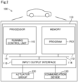
- Fig. 2 is an explanatory view showing a structure of the vehicle 100 in the present embodiment.
- the vehicle 100 is structured to enable itself to run by remote control.
- the vehicle 100 includes a vehicle control device 110 for controlling various units of the vehicle 100, an actuator group 120 including at least one actuator driven under the control of the vehicle control device 110, and a communication device 130 for communicating with the server device 200 via wireless communication.
- the actuator group 120 includes an actuator for a driving device for accelerating the vehicle 100, an actuator for a steering device for changing the traveling direction of the vehicle 100, and an actuator for a braking device for decelerating the vehicle 100.
- the driving device includes a battery, a driving motor driven by electric power of the battery, and wheels rotated by the driving motor.
- the actuator of the driving device includes a driving motor.
- the vehicle control device 110 is constituted of a computer with a processor 111, a memory 112, an input/output interface 113, and an internal bus 114.
- the processor 111, the memory 112, and the input/output interface 113 are connected via the internal bus 114 to enable bidirectional communication.
- the actuator group 120 and the communication device 130 are connected to the input/output interface 113.
- the processor 111 functions as a running control unit 115 by executing a computer program PG1 stored in advance in the memory 112.
- the running control unit 115 controls the actuator group 120.
- the running control unit 115 causes the vehicle 100 to run by controlling the actuator group 120 in response to the operation by the passenger.
- the running control unit 115 is capable of enabling the vehicle 100 to run by controlling the actuator group 120 in response to a running control signal received from the server device 200, regardless of whether or not the vehicle 100 has a passenger.
- the running control signal is a control signal for enabling the vehicle 100 to run.
- the running control signal includes the acceleration and the steering angle of the vehicle 100 as parameters.
- the running control signal may include the speed of the vehicle 100 as a parameter instead of, or in addition to, the acceleration of the vehicle 100.
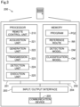
- Fig. 3 is an explanatory view showing a structure of the server device 200 in the present embodiment.
- the server device 200 is constituted of a computer with a processor 201, a memory 202, an input/output interface 203, and an internal bus 204.
- the processor 201, the memory 202, and the input/output interface 203 are connected via the internal bus 204 to enable bidirectional communication.
- the input/output interface 203 is connected to a communication device 205 for enabling communication with the vehicle 100 and the work equipment 300 via wireless communication.
- the communication device 205 is capable of communication with the vehicle 100 and the work equipment 300 via wireless communication, and is also capable of communication with the external sensor 250, the step management device 400, and the notification device 500 via wired or wireless communication.
- the processor 201 functions as a remote control unit 210, an acquisition unit 221, a generation unit 222, a transmission unit 223, a detection unit 224, and an execution unit 225 by executing a computer program PG2 stored in advance in the memory 202.
- the remote control unit 210 executes remote control of the vehicle 100. Specifically, the remote control unit 210 generates a running control signal using the detection results of the external sensor 250, and transmits the running control signal to the vehicle 100, thereby enabling the vehicle 100 to run by remote control.
- the acquisition unit 221 acquires individual information of a vehicle 100, which moves to a work place WS by remote control.
- the work place WS is the place where works are performed on the vehicle 100.
- the works include, for example, assembling parts, inspections, adjustments, repairs, and the like.
- the individual information includes information regarding the attributes of the vehicle 100.
- the attributes of the vehicle 100 include, for example, vehicle type, model code, color, dimensions, and the like.
- the attribute of the vehicle 100 can be distinguished by the shape of the vehicle 100. Specifically, in the present embodiment, the attribute of the vehicle 100 is the vehicle type.
- the shape of the vehicle 100 differs depending on the vehicle type. Therefore, it is possible to distinguish the shape of the vehicle 100 based on the vehicle type.
- the attribute of the vehicle 100 that can be distinguishable based on the shape of the vehicle 100 may be the model code or dimensions.
- the dimensions include, for example, the width of the vehicle 100, the height of the vehicle 100, and the length of the vehicle 100.
- the width, the height, and the length of the vehicle 100 may refer to the width, the height, and the length of the entire vehicle 100, or may refer to the width, the height, and the length from a predetermined position of the vehicle 100 to another predetermined position of the vehicle 100.
- the width of the vehicle 100 may be a width from the left front wheel of the vehicle 100 to the right front wheel of the vehicle 100.
- the attribute of the vehicle 100 may be an attribute that can be distinguished based on the color of the vehicle 100.
- the attribute of the vehicle 100 that can be distinguishable based on the color of the vehicle 100 may be, for example, the body color, the color of the mirror, and the roof color.
- the generation unit 222 generates equipment control signals according to the individual information of the vehicle 100 that moves to the work place WS.
- the equipment control signal is a control signal used to control work equipment.
- the transmission unit 223 transmits the equipment control signals to the work equipment 300.
- the detection unit 224 detects the state of the work equipment 300.
- the execution unit 225 executes at least one of a process of decelerating the vehicle 100, a process of changing the running route of the vehicle 100, and a process of notifying occurrence of an abnormality using the notification device 500, when the state of the work equipment 300 does not change according to the equipment control signal.
- the deceleration of the vehicle 100 includes stopping the vehicle 100.
- the server device 200 may not include the detection unit 224 and the execution unit 225.
- the external sensor 250 shown in Fig. 1 is a sensor located outside the vehicle 100.
- the external sensor 250 is used to detect the position and the orientation of the vehicle 100.
- the external sensor 250 is a camera provided in a factory FC.
- the external sensor 250 includes a communication device (not shown), and is capable of communication with the server device 200 via wired or wireless communication.
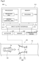
- Fig. 4 is an explanatory view showing a structure of the work equipment 300 in the present embodiment.
- the work equipment 300 is provided in the work place WS.
- the work equipment 300 is equipment that adjusts the traveling direction of the vehicle 100.
- the work equipment 300 includes an equipment control device 310, a pair of left and right guide rails 320, an actuator 330 that drives the guide rails 320, a sensor 340 for detecting the state of the guide rails 320, and a communication device 350 for communicating with the server device 200 via wireless communication.
- the guide rails 320 are placed on the floor of the work place WS.
- the floor of the work place WS, where the guide rails 320 are placed, is included in a track TR of the vehicle 100.
- the guide rails 320 is constituted of a pair of left guide rail and right guide rail.
- the left and right guide rails 320 each include a first member 321 and a second member 322.
- the end of the second member 322 is rotatably connected to the end of the first member 321.
- the first members 321 on the left and right guide rails 320 are arranged in parallel to each other.
- the second members 322 on the left and right guide rails 320 are arranged in such a way that the distance between them becomes narrower from the front side of the traveling direction of the vehicle 100 toward the back side of the traveling direction of the vehicle 100.
- the actuator 330 adjusts a gap D between the left and right guide rails 320 and an angle ⁇ between the left and right guide rails 320.
- the gap D of the guide rails 320 refers to the distance between the left and right first members 321, and the angle ⁇ of the guide rails refers to the angle between the left and right second members 322.
- the sensor 340 detects the gap D and the angle ⁇ of the guide rails 320 as the state of the guide rails 320.
- the sensor 340 may be implemented by, for example, an encoder.
- the value detected by the sensor 340 is referred to as a sensor value.
- the sensor value is transmitted to the server device 200.
- the guide rails 320 may not be configured such that the angle ⁇ of the guide rails 320 is changeable.
- the equipment control device 310 is constituted of a computer with a processor 311, a memory 312, an input/output interface 313, and an internal bus 314.
- the processor 311, the memory 312, and the input/output interface 313 are connected via the internal bus 314 to enable bidirectional communication.
- the actuator 330, the sensor 340, and the communication device 350 are connected to the input/output interface 313.
- the processor 311 functions as a reception unit 315 and a driving control unit 316 by executing a computer program PG3 stored in advance in the memory 312.
- the reception unit 315 receives the equipment control signals from the server device 200.
- the equipment control signal includes the gap D of the guide rails 320 and the angle ⁇ of the guide rails 320 as parameters.
- the driving control unit 316 adjusts the gap D of the guide rails 320 and the angle ⁇ of the guide rails 320 by driving the actuator 330 using the equipment control signal.
- the step management device 400 performs overall management of the production processes of the vehicle 100 in the factory FC.
- the step management device 400 is constituted of at least one computer.
- the step management device 400 has a database that stores various types of information of the vehicle 100.
- the various types of information stored in the database include the identification number, the vehicle type, the model code, the body color of the vehicle 100, the content of each production step, progress of the production step, and information regarding parts installed in the vehicle 100 in each production step.
- the step management device 400 includes a communication device (not shown), and is capable of communication with the server device 200 and various kinds of equipment in the factory FC via wired or wireless communication.
- the notification device 500 is a device for notifying the administrator of the system 10 and workers in the factory of occurrence of abnormality in the factory.
- the administrator of the system 10 and the workers in the factory are referred to as "administrator and the like".
- the notification device 500 is, for example, a warning buzzer provided in the factory or a warning lamp provided in the factory.
- the notification device 500 may be a tablet terminal carried by the administrator and the like.
- the notification device 500 includes a communication device (not shown), and is capable of communication with the server device 200 via wired or wireless communication.
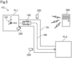
- Fig. 5 is an explanatory view showing a state in which the vehicle 100 runs by remote control in the factory FC.
- the factory FC has a first place PL1 and a second place PL2.
- the first place PL1 and the second place PL2 are connected by the track TR on which the vehicle 100 can run.
- a plurality of external sensors 250 are provided along the track TR.
- the first place PL1 is a place where the work for assembling the vehicles 100 is performed.
- the vehicle 100 assembled at the first place PL1 is capable of running by remote control, in other words, the vehicle 100 is capable of performing the three functions: "running,” “turning,” and “stopping" by remote control.
- the vehicle 100 moves from the first place PL1 to the second place PL2 by remote control.
- the second place PL2 is a place where the work for inspecting the vehicles 100 is performed.
- the work equipment 300 is provided at the second place PL2.
- the vehicle 100 that has passed the inspection at the second place PL2 is then shipped from the factory FC.
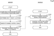
- Fig. 6 is a flowchart illustrating a process procedure of running control of the vehicle 100 in the first embodiment.
- the remote control unit 210 acquires vehicle location information of the vehicle 100 using detection results output from the external sensor 250, which is a sensor located outside the vehicle 100.
- the vehicle location information is position information that serves as the basis for generating running control signals.
- the vehicle location information includes the position and orientation of the vehicle 100 in the reference coordinate system of the factory FC.
- the reference coordinate system of the factory FC is the global coordinate system GC, and any location in the factory FC is expressed with X, Y, and Z coordinates in the global coordinate system GC.
- the external sensor 250 is the camera, and the external sensor 250 outputs a captured image as a detection result. That is, in the step S1, the remote control unit 210 acquires the vehicle location information using captured images acquired from the camera, which is the external sensor 250.
- the remote control unit 210 determines the outer shape of the vehicle 100 from the captured image, calculates the coordinates of a positioning point of the vehicle 100 in a coordinate system of the captured image, namely, in a local coordinate system, and converts the calculated coordinates to coordinates in the global coordinate system GC, thereby acquiring the location of the vehicle 100.
- the outer shape of the vehicle 100 in the captured image may be detected by inputting the captured image to a detection model DM using artificial intelligence, for example.
- the detection model DM is prepared in the system 10 or outside the system 10.
- the detection model DM is stored in advance in the memory 202 of the server device 200, for example.
- An example of the detection model DM is a learned machine learning model that was learned so as to realize either semantic segmentation or instance segmentation.
- a convolution neural network (CNN) learned through supervised learning using a learning dataset is applicable as this machine learning model.
- the learning dataset contains a plurality of training images including the vehicle 100, and a label showing whether each region in the training image is a region indicating the vehicle 100 or a region indicating a subject other than the vehicle 100, for example.
- a parameter for the CNN is preferably updated through backpropagation in such a manner as to reduce error between output result obtained by the detection model DM and the label.
- the remote control unit 210 can acquire the orientation of the vehicle 100 through estimation based on the direction of a motion vector of the vehicle 100 detected from change in location of a feature point of the vehicle 100 between frames of the captured images using optical flow process, for example.
- the remote control unit 210 determines a target location to which the vehicle 100 is to move next.
- the target location is expressed by X, Y, and Z coordinates in the global coordinate system GC.
- the memory 202 of the server device 200 contains the reference route RR stored in advance as a route along which the vehicle 100 is to run. The route is expressed by a node indicating a departure place, a node indicating a way point, a node indicating a destination, and a link connecting nodes to each other.
- the remote control unit 210 determines the target location to which the vehicle 100 is to move next using the vehicle location information and the reference route RR.
- the remote control unit 210 determines the target location on the reference route RR ahead of a current location of the vehicle 100.
- the remote control unit 210 In step S3, the remote control unit 210 generates a running control signal for causing the vehicle 100 to run toward the determined target location.
- the running control signal includes an acceleration and a steering angle of the vehicle 100 as parameters.
- the remote control unit 210 calculates a running speed of the vehicle 100 from transition of the location of the vehicle 100 and makes comparison between the calculated running speed and a target speed of the vehicle 100 determined in advance. If the running speed is lower than the target speed, the remote control unit 210 generally determines an acceleration in such a manner as to accelerate the vehicle 100. If the running speed is higher than the target speed as, the remote control unit 210 generally determines an acceleration in such a manner as to decelerate the vehicle 100.
- the remote control unit 210 determines a steering angle and an acceleration in such a manner as to prevent the vehicle 100 from deviating from the reference route RR. If the vehicle 100 is not on the reference route RR, in other words, if the vehicle 100 deviates from the reference route RR, the remote control unit 210 determines a steering angle and an acceleration in such a manner as to return the vehicle 100 to the reference route RR.
- the running control signal may include the speed of the vehicle 100 as a parameter instead of or in addition to the acceleration of the vehicle 100.
- step S4 the remote control unit 210 transmits the generated running control signal to the vehicle 100.
- the remote control unit 210 repeats the acquisition of vehicle location information, the determination of a target location, the generation of a running control signal, the transmission of the running control signal, and others in a predetermined cycle.
- step S5 the running control unit 115 of the vehicle 100 receives the running control signal transmitted from the remote control unit 210.
- the running control unit 115 controls actuator group 120 using the received running control signal, thereby causing the vehicle 100 to run at the acceleration and the steering angle indicated by the running control signal.
- the running control unit 115 repeats the reception of a running control signal and the control over actuator group 120 in a predetermined cycle.
- Fig. 7 is a flowchart showing procedures in the process of operation control of the work equipment 300. While referring to Fig. 7 , the following describes a control method of the work equipment 300.
- the acquisition unit 221 acquires the individual information of the vehicle 100 that will move to the work place WS next.
- the vehicle 100 that will move to the work place WS next refers to the vehicle 100 that enters the guide rails 320.
- the acquisition unit 221 acquires the vehicle type of the vehicle 100 as the individual information.
- the vehicle type relates to the width of the vehicle 100, as the width W of the vehicle 100 varies depending on the vehicle type.
- the acquisition unit 221 acquires captured images from the external sensor 250 that captures images of the vehicle 100 moving to the work place WS, and acquires the vehicle type of the vehicle 100 using the captured images.
- the vehicle type of the vehicle 100 included in the captured image can be acquired, for example, by inputting the captured image into a classification model CM that utilizes artificial intelligence.
- the classification model CM is prepared, for example, inside the system 10 or outside the system 10, and stored in advance in the memory 202 of the server device 200.
- Examples of the classification model CM include a trained machine learning model that has been trained to identify the vehicle type of the vehicle 100 included in the captured image.
- a CNN trained by supervised learning using a training data set may be used.
- the training data set includes, for example, a plurality of training images with the vehicle 100, and labels that indicate the vehicle type of the vehicle 100 included in the training images.
- the acquisition unit 221 may acquire the vehicle type of the vehicle 100 that moves to the work place WS next from the step management device 400.
- the generation unit 222 determines whether or not the vehicle type of the vehicle 100 that enters the guide rails 320 next is different from the vehicle type of the vehicle 100 that has entered the guide rails 320 earlier.
- the vehicle 100 that has entered the guide rails 320 earlier refers to the vehicle 100 that has entered the guide rails 320 immediately before the vehicle 100 that will enter the guide rails 320 next.
- the vehicle 100 that will enter the guide rails 320 next is referred to as a subsequent vehicle and the vehicle 100 that has entered the guide rails 320 earlier is referred to as a preceding vehicle.
- the preceding vehicle may not have exited from the guide rails 320.
- the generation unit 222 If it is determined that the vehicle type is different between the preceding vehicle and the subsequent vehicle in the step S120, the generation unit 222 generates an equipment control signal according to the vehicle type of the subsequent vehicle in the step S130.
- a database in which the vehicle type is associated with the gap D and the angle ⁇ of the guide rails 320 is stored in advance in the memory 202 of the server device 200.
- the generation unit 222 generates, using the database, an equipment control signal that drives the actuator 330 to adjust the gap D and the angle ⁇ of the guide rails 320 according to the vehicle type of the subsequent vehicle.
- the generation unit 222 ends the process without generating the equipment control signal.
- the transmission unit 223 determines whether or not the preceding vehicle has exited from the guide rails 320.
- the transmission unit 223 acquires vehicle position information of the preceding vehicle, for example, from the remote control unit 210, and determines whether or not the preceding vehicle has exited from the guide rails 320 using the vehicle position information.
- the transmission unit 223 may determine whether or not the preceding vehicle has exited from the guide rails 320 using information acquired from the step management device 400. For example, the transmission unit 223 can determine that the preceding vehicle has exited from the guide rails 320 when the work that is performed on the preceding vehicle after the preceding vehicle is exited from the guide rails 320 has started.
- the transmission unit 223 repeats the step S140 until it is determined that the preceding vehicle has exited from the guide rails 320. In contrast, if it is determined in the step S140 that the preceding vehicle has exited from the guide rails 320, the transmission unit 223 transmits the equipment control signal to the work equipment 300 in the step S150.
- the driving control unit 316 of the work equipment 300 changes the gap D and the angle ⁇ of the guide rails 320 by driving the actuator 330 using the received equipment control signal.
- the driving control unit 316 acquires the sensor value from the sensor 340 and transmits the sensor value to the server device 200.
- the detection unit 224 starts counting time using the timer function, and, in the step S170, the detection unit 224 determines whether or not the sensor value has been received from the work equipment 300.
- the sensor value includes the gap D of the guide rails 320 and the angle ⁇ of the guide rails 320. If it is not determined that the sensor value has been received in the step S170, in the step S175, the detection unit 224 determines whether or not a predetermined time has elapsed since the start of counting. The predetermined time mentioned above is set to be shorter than the time it takes for the vehicle 100 to enter the guide rails 320 from the start of counting. If it is not determined that the predetermined time has elapsed since the start of counting in the step S175, the detection unit 224 returns the process to the step S170 and determines again whether or not the sensor value has been received.
- the detection unit 224 determines whether or not the sensor value is appropriate. If both the gap D and the angle ⁇ of the guide rails 320 are within a predetermined range according to the vehicle type of the subsequent vehicle, the detection unit 224 determines that the sensor value is appropriate. When at least one of the gap D and the angle ⁇ of the guide rails 320 falls out of the above-mentioned predetermined range, the detection unit 224 determines that the sensor value is inappropriate. If the sensor value is determined to be appropriate in the step S180, in the step S190, the detection unit 224 resets the time counting by the timer function and ends the process.
- the driving control unit 316 may transmit the determination result as to whether or not the actuator 330 has been driven in response to the equipment control signal to the server device 200, instead of transmitting the sensor value to the server device 200.
- the detection unit 224 may confirm that the guide rails 320 have been operated based on the determination result. Further, the detection unit 224 may confirm that the guide rails 320 have been operated in response to the equipment control signal using the external sensor 250, instead of confirming that the guide rails 320 have been operated based on the sensor value acquired from the driving control unit 316.
- the execution unit 225 executes a process of instructing the remote control unit 210 to stop the subsequent vehicle, and a process of notifying the administrator and the like of the occurrence of an abnormality using the notification device 500, and then ends this process.
- the remote control unit 210 Upon receiving the instruction from the execution unit 225, the remote control unit 210 generates a running control signal to stop the subsequent vehicle, and transmits the running control signal to the subsequent vehicle.
- the notification device 500 that has received the instruction from the execution unit 225 executes the notification.
- the execution unit 225 may instruct the remote control unit 210 to decelerate the subsequent vehicle within a range that does not stop the subsequent vehicle, instead of instructing the remote control unit 210 to stop the subsequent vehicle.
- the execution unit 225 may instruct the remote control unit 210 to make the subsequent vehicle run while avoiding the guide rails 320, instead of instructing the remote control unit 210 to stop or decelerate the subsequent vehicle.
- Fig. 8 is an explanatory view showing the operation of the work equipment 300.
- Fig. 8 illustrates a plurality of the vehicles 100A and 100B.
- the vehicle 100A will be referred to as a first vehicle 100A
- the vehicle 100B will be referred to as a second vehicle 100B.
- the control signal corresponding to the vehicle type of the first vehicle 100A will be referred to as a first control signal
- the control signal corresponding to the vehicle type of the second vehicle 100B will be referred to as a second control signal.
- the first vehicle 100A and the second vehicle 100B without specifically distinguishing them from each other, they will simply be referred to as a vehicle 100.
- the first control signal and the second control signal In cases of describing the first control signal and the second control signal without specifically distinguishing them from each other, they will simply be referred to as a control signal.
- the first control signal is transmitted from the server device 200 to the work equipment 300, and the gap D and the angle ⁇ of the guide rails 320 are adjusted to the gap D1 and the angle ⁇ 1 corresponding to the vehicle type of the first vehicle 100A.
- the vehicle type of the first vehicle 100A is different from the vehicle type of the second vehicle 100B.
- the width W1 of the first vehicle 100A is different from the width W2 of the second vehicle 100B.
- the gap D and the angle ⁇ of the guide rails 320 are adjusted to the gap D2 and the angle ⁇ 2 corresponding to the vehicle type of the second vehicle 100B.
- the gap D2 and the angle ⁇ 2 of the guide rails 320 corresponding to the vehicle type of the second vehicle 100B are the same as the gap D1 and the angle ⁇ 1 of the guide rails 320 corresponding to the vehicle type of the first vehicle 100A. Therefore, it is not necessary to change the gap D and the angle ⁇ of the guide rails 320 during the time after the first vehicle 100A exits from the guide rails 320 until the second vehicle 100B enters the guide rails 320.
- the second control signal is not transmitted from the server device 200 to the work equipment 300 during the time after the first vehicle 100A exits from the guide rails 320 until the second vehicle 100B enters the guide rails 320. Therefore, also when the second vehicle 100B enters the guide rails 320, the gap D and the angle ⁇ of the guide rails 320 are kept at the gap D1 and the angle ⁇ 1 corresponding to the vehicle type of the first vehicle 100A.
- the server device 200 generates an equipment control signal corresponding to the vehicle type of the vehicle 100 and transmits the equipment control signal to the work equipment 300.
- This allows the work equipment 300 to operate using the equipment control signal received from the server device 200, thereby switching to an appropriate state according to the vehicle type of the vehicle 100.
- the gap D and the angle ⁇ of the guide rails 320 are switched to appropriate gap and angle according to the vehicle type of the vehicle 100 that enters the guide rails 320. Therefore, it is possible to appropriately adjust the traveling direction of the vehicle 100.
- the generation unit 222 of the server device 200 when the vehicle type of the first vehicle 100A, which is the preceding vehicle, is different from the vehicle type of the second vehicle 100B, which is the subsequent vehicle, the generation unit 222 of the server device 200 generates the first control signal, which is an equipment control signal corresponding to the vehicle type of the first vehicle 100A, and the second control signal, which is an equipment control signal corresponding to the vehicle type of the second vehicle 100B, and when the first vehicle 100A, which is the preceding vehicle, and the second vehicle 100B, which is the subsequent vehicle, have the same vehicle type, the generation unit 222 generates the first control signal without generating the second control signal. Therefore, it is possible to eliminate unnecessary generation of the same equipment control signals.
- the server device 200 includes the transmission unit 223 that transmits the equipment control signal, and the work equipment 300 includes the reception unit 315 that receives the equipment control signal, and the driving control unit 316 that drives the actuator 330 using the equipment control signal. This allows the server device 200 to control the work equipment 300 by remote control.
- the server device 200 further generates the running control signal for causing the vehicle 100 to run by unmanned driving, and transmits the running control signal to the vehicle 100. In this way, the server device 200 enables the vehicle 100 to cooperate with the work equipment 300.
- the detection unit 224 detects abnormalities in the gap D and the angle ⁇ of the guide rails 320, and the execution unit 225 instructs the remote control unit 210 not to allow the vehicle 100 to enter the guide rails 320 when an abnormality is detected by the detection unit 224. In this way, it is possible to prevent defects in adjusting the traveling direction of the vehicle 100 by the guide rails 320. Further, when an abnormality is detected by the detection unit 224, the execution unit 225 notifies the notification device 500 of the occurrence of the abnormality. This enables the administrator and the like to promptly recognize the occurrence of the abnormality.
- Fig. 9 is an explanatory view showing a structure of a work equipment 300b having an equipment control device 310, which is a control device in the second embodiment.
- the present embodiment differs from the first embodiment in that the server device 200 does not generate the equipment control signal, instead, the equipment control device 310 generates the equipment control signal.
- Other structures are the same as those in the first embodiment, unless otherwise specified.
- the processor 311 of the equipment control device 310 functions as an acquisition unit 351, a generation unit 352, a driving control unit 316, a detection unit 354, and an execution unit 355 by executing a computer program PG3 stored in advance in the memory 312.
- the functions of the acquisition unit 351, the generation unit 352, the driving control unit 316, the detection unit 354, and the execution unit 355 are basically the same as those of the acquisition unit 221, the generation unit 222, the driving control unit 316, the detection unit 224, and the execution unit 225 in the first embodiment.
- the server device 200 does not have the acquisition unit 221, the generation unit 222, the transmission unit 223, the detection unit 224, and the execution unit 225 shown in Fig. 3 .
- the acquisition unit 351 then acquires the individual information of the vehicle 100 that will move to the work place WS next.
- the acquisition unit 351 acquires the vehicle type as the individual information.
- a classification model CM and a database in which the vehicle type is associated with the gap D and the angle ⁇ of the guide rails 320 are stored in advance in the memory 312 of the equipment control device 310.
- the acquisition unit 351 acquires the vehicle type of the vehicle 100 that will move to the work place WS next using the captured image acquired from the external sensor 250 and the classification model CM.
- the generation unit 352 generates an equipment control signal corresponding to the vehicle type of the vehicle 100 that will move to the work place WS next using the acquired vehicle type and the database.
- the driving control unit 316 drives the actuator 330 using the equipment control signal generated by the generation unit 352.
- the detection unit 354 detects abnormalities in the work equipment 300b using the sensor 340.
- the execution unit 355 performs the process of instructing the server device 200 to stop the vehicle 100 that will move to the work place WS next when an abnormality is detected in the work equipment 300b, as well as the process of notifying the administrator and the like of the occurrence of the abnormality using the notification device 500.
- the equipment control device 310 may not include the detection unit 354 and the execution unit 355.
- the execution unit 355 may directly instruct the vehicle 100 that will move to the work place WS next to stop, without intervention of the server device 200.
- the equipment control device 310 in the present embodiment described above it is possible to adjust the gap D and the angle ⁇ of the guide rails 320 according to the vehicle type of the vehicle 100 that will enter the guide rails 320 next, without using remote control of the server device 200.
- Fig. 10 is an explanatory view showing a structure of a work equipment 300c in the third embodiment.
- the present embodiment differs from the first embodiment in that the work equipment 300c is equipment that sprays a fluid onto the vehicle 100, and that the generation unit 222 of the server device 200 generates an equipment control signal for adjusting the spray starting position of the fluid with respect to the vehicle 100.
- Other structures are the same as those in the first embodiment, unless otherwise specified.
- the work equipment 300c is equipment that sprays water.
- the work equipment 300c is used for the work of inspecting water resistance of the vehicle 100. In the water resistance inspection, water is sprayed onto the predetermined range of the vehicle 100 to inspect whether or not the water enters the interior of the vehicle 100.
- the work equipment 300c includes an arm unit 361 and a nozzle unit 362.
- the arm unit 361 is structured as a vertical articulated robot arm.
- the arm unit 361 is not limited to a vertical articulated robot arm, but may also be structured as, for example, a horizontal articulated robot arm, an orthogonal robot arm, or a parallel link robot arm.
- the nozzle unit 362 is attached to the top end portion of the arm unit 361. The nozzle unit 362 sprays water.
- the arm unit 361 is driven by the actuator 330.
- the acquisition unit 221 of the server device 200 acquires the individual information of the vehicle 100 onto which the water is to be sprayed.
- the acquisition unit 221 acquires the vehicle type of the vehicle 100 as the individual information of the vehicle 100.
- the generation unit 222 generates an equipment control signal that includes the water spray starting position as a parameter.
- the height of the vehicle 100 varies depending on the vehicle type.
- the generation unit 222 generates the equipment control signal such that, for example, the higher the vehicle height of the vehicle type, the higher the water spray starting position.
- a database in which the vehicle type is associated with the spray starting position is stored in advance in the memory 202.
- the generation unit 222 generates the equipment control signal using the vehicle type information acquired by the acquisition unit 221 and the database.
- the transmission unit 223 transmits the equipment control signal generated by the generation unit 222 to the work equipment 300c.
- the generation unit 222 does not generate the equipment control signal for subsequent vehicles when the preceding vehicle and the subsequent vehicle have the same vehicle type.
- the transmission unit 223 transmits the equipment control signal generated for the preceding vehicle to the work equipment 300c before the subsequent vehicle enters the work place WS.
- the work equipment 300c operates using the same equipment control signal both during the inspection for the preceding vehicle and the inspection for the subsequent vehicle.
- the water spray starting position can be adjusted according to the vehicle type of the vehicle 100 onto which the water is to be sprayed.
- the work equipment 300c may be structured such that a fluid other than water is sprayed from the nozzle unit 362.
- the work equipment 300c may be structured such that a fluid other than water or a gas such as hot air is sprayed from the nozzle unit 362.
- Fig. 11 is an explanatory view showing a structure of a work equipment 300d in the fourth embodiment.
- the present embodiment differs from the first embodiment in that the work equipment 300d is equipment that adjusts a wheel alignment of the vehicle 100, and that the generation unit 222 of the server device 200 generates an equipment control signal for adjusting the standby position of the work equipment 300d.
- Other structures are the same as those in the first embodiment, unless otherwise specified.
- the work equipment 300d is provided under the floor of the work place WS, where the work of adjusting the wheel alignment of the vehicle 100 is performed. In the work of adjusting wheel alignment, the wheel alignment of the vehicle 100 is adjusted by adjusting the degree of tightening the wheel alignment adjustment screw provided on a lower part of the vehicle 100.
- the work equipment 300d includes an arm unit 371 and a hand unit 372.
- the arm unit 371 is structured as a vertical articulated robot arm.
- the arm unit 371 is not limited to a vertical articulated robot arm, but may also be structured as, for example, a horizontal articulated robot arm, an orthogonal robot arm, or a parallel link robot arm.
- the hand unit 372 is attached to the top end portion of the arm unit 371.
- the hand unit 372 is structured such that the degree of tightening the wheel alignment adjustment screw of the vehicle 100 is changeable.
- the arm unit 371 is driven by the actuator 330. By driving the arm unit 371, it is possible to change the position and orientation of the hand unit 372. In other words, by driving the arm unit 371, it is possible to change the standby position of the hand unit 372.
- the standby position of the hand unit 372 may also be referred to as the standby position of the work equipment 300d.
- the acquisition unit 221 of the server device 200 acquires the individual information of the vehicle 100 for which the wheel alignment is to be adjusted.
- the acquisition unit 221 acquires the vehicle type information of the vehicle 100 as the individual information of the vehicle 100.
- the generation unit 222 generates an equipment control signal that includes the coordinates of the standby position of the hand unit 372 as a parameter.
- a database in which the vehicle type is associated with the coordinates of the standby position is stored in advance in the memory 202.
- the generation unit 222 generates the equipment control signal using the vehicle type information acquired by the acquisition unit 221 and the database.
- the transmission unit 223 transmits the equipment control signal generated by the generation unit 222 to the work equipment 300d.
- the position of the wheel alignment adjustment screw varies depending on the vehicle type.
- the standby position of the hand unit 372 is adjusted so that the hand unit 372 does not collide with the vehicle 100 when the vehicle 100 enters the work place WS.
- the standby position of the hand unit 372 is adjusted so that the hand unit 372 is located near the wheel alignment adjustment screw of the vehicle 100 when the vehicle 100 stops at the work place WS.
- the generation unit 222 does not generate the equipment control signal for subsequent vehicles when the preceding vehicle and the subsequent vehicle have the same vehicle type.
- the transmission unit 223 transmits the equipment control signal generated for the preceding vehicle to the work equipment 300d before the subsequent vehicle enters the work place WS.
- the work equipment 300d operates using the same equipment control signal both during the adjustment work for the preceding vehicle and the adjustment work for the subsequent vehicle.
- server device 200 of the present embodiment described above it is possible to adjust the standby position of the work equipment 300d according to the vehicle type of the vehicle 100 for which the wheel alignment is to be adjusted.
- Fig. 12 is an explanatory view showing a structure of a work equipment 300e in the fifth embodiment.
- the present embodiment differs from the first embodiment in that the work equipment 300e is equipment that emits an electromagnetic wave onto the vehicle 100, and that the generation unit 222 generates an equipment control signal for adjusting the wavelength of the electromagnetic wave.
- Other structures are the same as those in the first embodiment, unless otherwise specified.
- the work equipment 300e is equipment that emits visible light to the vehicle 100.
- the work equipment 300e is used, for example, for an inspection for exterior appearance of the vehicle 100.
- the work equipment 300e includes an arm unit 381 and a light 382.
- the arm unit 381 is structured as a vertical articulated robot arm.
- the arm unit 371 is not limited to a vertical articulated robot arm, but may also be structured as, for example, a horizontal articulated robot arm, an orthogonal robot arm, or a parallel link robot arm.
- the light 382 is attached to the top end portion of the arm unit 381.
- the light 382 is structured to be capable of changing the wavelength of the light to be emitted, in other words, the color of the light to be emitted.
- the arm unit 381 is driven by the actuator 330. By driving the arm unit 381, it is possible to change the position and orientation of the light 382. In other words, by driving the arm unit 381, it is possible to change the position and orientation of light emission with respect to the vehicle 100.
- the acquisition unit 221 of the server device 200 acquires the individual information of the vehicle 100 to be inspected.
- the acquisition unit 221 acquires the body color information of the vehicle 100 as the individual information of the vehicle 100.
- the generation unit 222 generates an equipment control signal that includes the wavelength of the light emitted from the light 382 as a parameter.
- a database in which the body color is associated with the wavelength of light is stored in advance in the memory 202.
- the generation unit 222 generates the equipment control signal using the body color information acquired by the acquisition unit 221 and the database.
- the transmission unit 223 transmits the equipment control signal generated by the generation unit 222 to the work equipment 300e.
- the work equipment 300e is not used for the inspection for exterior appearance of the vehicle 100, but, for example, for the inspection of leakage of liquid, such as a coolant. If the coolant contains a fluorescent paint, the light 382 is adjusted to emit light having a wavelength that causes the fluorescent paint to produce luminescence.
- the generation unit 222 does not generate the equipment control signal for changing the wavelength of light emitted from the light 382 according to the body color of the subsequent vehicle.
- the server device 200 of the present embodiment described above it is possible to adjust the form of lighting by the work equipment 300e according to the body color of the vehicle 100 to be inspected.
- the work equipment 300e may be structured to emit ultraviolet light, infrared light, or the like, instead of visible light.
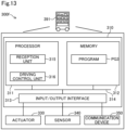
- Fig. 13 is an explanatory view showing a structure of a work equipment 300f in the sixth embodiment.
- the present embodiment differs from the first embodiment in that the work equipment 300f is equipment that transports vehicle parts to be attached to the vehicle 100.
- Other structures are the same as those in the first embodiment, unless otherwise specified.
- the work equipment 300f is structured as an unmanned transport vehicle that runs by remote control of the server device 200.
- the server device 200 is capable of causing the work equipment 300f to run, for example, by the same method as that for causing the vehicle 100 to run by remote control.
- the work equipment 300f is assigned to each vehicle 100, and runs by following the vehicle 100.
- the work equipment 300f transports parts to be attached to the vehicle 100 assigned.
- the work equipment 300f includes a cargo bed 391.
- the cargo bed 391 is loaded with parts to be attached to the vehicle 100.
- the acquisition unit 221 of the server device 200 acquires the individual information of the vehicle 100 to which the parts are to be attached.
- the acquisition unit 221 acquires the vehicle type of the vehicle 100 as the individual information of the vehicle 100.
- the generation unit 222 generates an equipment control signal for enabling the work equipment 300f to run by following the vehicle 100.
- the generation unit 222 acquires, for example, acceleration and steering angle of the vehicle 100 from the remote control unit 210, and generates an equipment control signal for causing the work equipment 300f to run at the same acceleration and steering angle as those of the vehicle 100.
- the transmission unit 223 transmits the equipment control signal generated by the generation unit 222 to the work equipment 300f.
- Fig. 14 is an explanatory view showing operation of the work equipment 300f in the present embodiment.
- Fig. 14 illustrates two vehicles 100A and 100B, and two units of work equipment 300fA and 300fB.
- the vehicle 100A is referred to as a first vehicle 100A
- the vehicle 100B is referred to as a second vehicle 100B.
- the work equipment 300fA is referred to as a first work equipment 300fA
- the work equipment 300fB is referred to as a second work equipment 300fB.
- the first work equipment 300fA runs by following the first vehicle 100A and the second work equipment 300fB runs by following the second vehicle 100B.
- the first vehicle 100A and the second vehicle 100B run in tandem, one behind the other.
- the first work equipment 300fA and the second work equipment 300fB run in tandem, one behind the other.
- a robot arm is provided on each running route for the vehicles 100A and 100B to attach the parts loaded on the work equipment 300fA and 300fB to the vehicles 100A and 100B.
- the parts loaded on the cargo bed 391 of the first work equipment 300fA are attached to the first vehicle 100A by the robot arm.
- the parts loaded on the cargo bed 391 of the second work equipment 300fB are attached to the second vehicle 100B by the robot arm.
- the server device 200 changes the order of alignment of the first work equipment 300fA and the second work equipment 300fB. In other words, if the first vehicle 100A is running ahead of the second vehicle 100B, the first work equipment 300fA will run ahead of the second work equipment 300fB, and if the second vehicle 100B is running ahead of the first vehicle 100A, the second work equipment 300fB will run ahead of the first work equipment 300fA.
- the order of alignment of the first work equipment 300fA and the second work equipment 300fB is changed according to the order of alignment of the first vehicle 100A and the second vehicle 100B. If the vehicle type of the first vehicle 100A is different from the vehicle type of the second vehicle 100B, the parts attached to these vehicles are also different. If the first work equipment 300fA is running ahead of the second work equipment 300fB even though the second vehicle 100B is running ahead of the first vehicle 100A, there is a possibility that the parts loaded on the first work equipment 300fA are attached to the second vehicle 100B by the robot arm.
- the server device 200 adjusts the second work equipment 300fB to run ahead of the first work equipment 300fA when the second vehicle 100B is running ahead of the first vehicle 100A. Therefore, it is possible to prevent attaching incorrect parts to the vehicle 100 by the robot arm.
- the server device 200 may control a robot arm 399, in addition to the vehicle 100 and the work equipment 300f. In case that the order of alignment of the vehicles 100 is changed and the position of the parts to be held by the robot arm 399 next is changed accordingly, the server device 200 may control the robot arm 399 so that the robot arm 399 properly holds the parts and attaches the parts to the vehicle 100.
- Fig. 15 is an explanatory view showing a structure of a vehicle 100 according to the seventh embodiment.
- the present embodiment differs from the first embodiment in that the vehicle 100 runs by autonomous control of the vehicle 100 instead of remote control by the server device 200.
- Other structures are the same as those in the first embodiment, unless otherwise specified.
- the vehicle 100 is structured to be capable of running by autonomous control.
- the vehicle 100 is capable of communication with the external sensor 250 via wireless communication using the communication device 130.
- a detection model DM and a reference route RR are stored in the memory 112 in advance.
- the running control unit 115 generates a running control signal by itself and causes the vehicle 100 to run by controlling the actuator group 120 using the generated running control signal.
- the server device 200 does not have the remote control unit 210.
- Fig. 16 is a flowchart showing procedures in the process of running control of the vehicle 100 in the present embodiment.
- the running control unit 115 acquires the vehicle position information using the detection results output from a camera, which is the external sensor 250.
- the running control unit 115 determines the target location to which the vehicle 100 should go next.
- the running control unit 115 generates a running control signal for causing the vehicle 100 to run toward the determined target location.
- the running control unit 115 controls the actuator group 120 using the generated running control signal, thereby causing the vehicle 100 to run according to the parameters indicated by the running control signal.
- the running control unit 115 repeats the acquisition of the vehicle position information, the determination of the target location, the generation of the running control signal, and the control of the actuator group 120, in a predetermined cycle.
- the vehicle 100 can be made run by autonomous control of the vehicle 100 without the remote control of the vehicle 100 by the server device 200.
- Each of the embodiments described above shows a case in which the acquisition units 221 and 251 acquire the individual information of the preceding vehicle and the individual information of the subsequent vehicle, and, when the content of the individual information of the preceding vehicle differs from the content of the individual information of the subsequent vehicle, the generation units 222 and 252 generate the first control signal, which is a control signal according to the individual information of the preceding vehicle, and the second control signal, which is a control signal according to the individual information of the subsequent vehicle, and, when the individual information of the preceding vehicle and the individual information of the subsequent vehicle have the same content, the generation units 222 and 252 generate the first control signal without generating the second control signal.
- the generation units 222 and 352 may also be structured to generate the first control signal and the second control signal even when the individual information of the preceding vehicle and the individual information of the subsequent vehicle have the same content.
- the transmission unit 223 transmits the first control signal and the second control signal to the work equipment 300-300f, and, when the individual information of the preceding vehicle and the individual information of the subsequent vehicle have the same content, the transmission unit 223 transmits the first control signal to the work equipment 300-300f without transmitting the second control signal to the work equipment 300-300f.
- the first control signal is transmitted to the work equipment 300-300f without transmitting the second control signal to the work equipment 300-300f, thereby eliminating unnecessary transmission of the same control signals.
- the transmission unit 223 may be structured to transmit the first control signal and the second control signal to the work equipment 300-300f even when the individual information of the preceding vehicle and the individual information of the subsequent vehicle have the same content.
- the driving control unit 316 of the work equipment 300-300f may be structured to drive the actuator 330 using the first control signal and then drive the actuator 330 using the second control signal when the content of the individual information of the preceding vehicle is different from the content of the individual information of the subsequent vehicle, and drive the actuator 330 using the first control signal without subsequently driving the actuator 330 using the second control signal when the individual information of the preceding vehicle and the individual information of the subsequent vehicle have the same content.
- the external sensor 250 is not limited to the camera but may be the distance measuring device, for example.
- the distance measuring device is a light detection and ranging (LiDAR) device, for example.
- detection result output from the external sensor 250 may be three-dimensional point cloud data representing the vehicle 100.
- the server 200 and the vehicle 100 may acquire the vehicle location information through template matching using the three-dimensional point cloud data as the detection result and reference point cloud data, for example.
- the server 200 performs the processing from acquisition of vehicle location information to generation of a running control signal.
- the vehicle 100 may perform at least part of the processing from acquisition of vehicle location information to generation of a running control signal.
- embodiments (1) to (3) described below are applicable, for example.
- the vehicle 100 may be equipped with an internal sensor, and detection result output from the internal sensor may be used in at least one of generation of a route and generation of a running control signal.
- the vehicle 100 may acquire detection result from the internal sensor, and in generating the route, may reflect the detection result from the internal sensor in the route.
- the vehicle 100 may acquire detection result from the internal sensor, and in generating the running control signal, may reflect the detection result from the internal sensor in the running control signal.
- the vehicle 100 acquires vehicle location information using detection result from the external sensor.
- the vehicle 100 may be equipped with an internal sensor, the vehicle 100 may acquire vehicle location information using detection result from the internal sensor, determine a target location to which the vehicle 100 is to move next, generate a route from a current location of the vehicle 100 indicated by the acquired vehicle location information to the target location, generate a running control signal for running along the generated route, and control the actuator group 120 of the vehicle 100 using the generated running control signal.
- the vehicle 100 is capable of running without using any detection result from an external sensor.
- the vehicle 100 may acquire target arrival time or traffic congestion information from outside the vehicle 100 and reflect the target arrival time or traffic congestion information in at least one of the route and the running control signal.
- the server 200 automatically generates a running control signal to be transmitted to the vehicle 100.
- the server 200 may generate a running control signal to be transmitted to the vehicle 100 in response to operation by an external operator existing outside the vehicle 100.
- the external operator may operate an operating device including a display on which a captured image output from the external sensor is displayed, steering, an accelerator pedal, and a brake pedal for operating the vehicle 100 remotely, and a communication device for making communication with the server 200 through wire communication or wireless communication, for example, and the server 200 may generate a running control signal responsive to the operation on the operating device.
- the vehicle 100 is simply required to have a configuration to become movable by unmanned driving.
- the vehicle 100 may embodied as a platform having the following configuration, for example.
- the vehicle 100 is simply required to include at least actuators and a controller. More specifically, in order to fulfill three functions including "run,” “turn,” and “stop” by unmanned driving, the actuators may include a driving device, a steering device and a braking device. The actuators are controlled by the controller that controls running of the vehicle 100. In order for the vehicle 100 to acquire information from outside for unmanned driving, the vehicle 100 is simply required to include the communication device further.
- the vehicle 100 to become movable by unmanned driving is not required to be equipped with at least some of interior components such as a driver's seat and a dashboard, is not required to be equipped with at least some of exterior components such as a bumper and a fender or is not required to be equipped with a bodyshell.
- a remaining component such as a bodyshell may be mounted on the vehicle 100 before the vehicle 100 is shipped from a factory, or a remaining component such as a bodyshell may be mounted on the vehicle 100 after the vehicle 100 is shipped from a factory while the remaining component such as a bodyshell is not mounted on the vehicle 100.
- Each of components may be mounted on the vehicle 100 from any direction such as from above, from below, from the front, from the back, from the right, or from the left. Alternatively, these components may be mounted from the same direction or from respective different directions.
- the location determination for the platform may be performed in the same way as for the vehicle 100 in the first embodiments.
- the vehicle 100 may be manufactured by combining a plurality of modules.
- the module means a unit composed of one or more components grouped according to a configuration or function of the vehicle 100.
- a platform of the vehicle 100 may be manufactured by combining a front module, a center module and a rear module.
- the front module constitutes a front part of the platform
- the center module constitutes a center part of the platform
- the rear module constitutes a rear part of the platform.
- the number of the modules constituting the platform is not limited to three but may be equal to or less than two, or equal to or greater than four.
- any parts of the vehicle 100 different from the platform may be modularized.
- modules may include an arbitrary exterior component such as a bumper or a grill, or an arbitrary interior component such as a seat or a console.
- vehicle 100 not also any types of moving object may be manufactured by combining a plurality of modules.
- a module may be manufactured by joining a plurality of components by welding or using a fixture, for example, or may be manufactured by forming at least part of the module integrally as a single component by casting.
- a process of forming at least part of a module as a single component is also called Giga-casting or Mega-casting.
- Giga-casting can form each part conventionally formed by joining multiple parts in a moving object as a single component.
- the front module, the center module, or the rear module described above may be manufactured using Giga-casting, for example.
- a configuration for realizing running of a vehicle by unmanned driving is also called a "Remote Control auto Driving system”.
- Conveying a vehicle using Remote Control Auto Driving system is also called “self-running conveyance”.
- Producing the vehicle using self-running conveyance is also called “self-running production”.
- self-running production for example, at least part of the conveyance of vehicles is realized by self-running conveyance in a factory where the vehicle is manufactured.
- the control and the method described in the present disclosure may be realized by a dedicated computer provided by configuring a processor and a memory programmed in such a manner as to implement one or a plurality of functions embodied by a computer program.
- the controller and the method described in the present disclosure may be realized by a dedicated computer provided by configuring a processor using one or more dedicated hardware logic circuits.
- the controller and the method described in the present disclosure may be realized by one or more dedicated computers configured using a combination of a processor and a memory programmed in such a manner as to implement one or a plurality of functions, and a processor configured using one or more hardware logic circuits.
- the computer program may be stored as an instruction to be executed by a computer into a computer-readable tangible non-transitory recording medium.
Landscapes
- Engineering & Computer Science (AREA)
- Physics & Mathematics (AREA)
- Automation & Control Theory (AREA)
- General Physics & Mathematics (AREA)
- Remote Sensing (AREA)
- Radar, Positioning & Navigation (AREA)
- Aviation & Aerospace Engineering (AREA)
- Power Engineering (AREA)
- Transportation (AREA)
- Mechanical Engineering (AREA)
- Control Of Position, Course, Altitude, Or Attitude Of Moving Bodies (AREA)
- Traffic Control Systems (AREA)
- Guiding Agricultural Machines (AREA)
Abstract
Description
- This application claims priority to
Japanese Patent Application No. 2023-199108, filed November 24, 2023 - The present disclosure relates to a control device and a control method.
- There are known technologies for causing vehicles to run by unmanned driving during vehicle production steps (for example,
Japanese Patent Application Publication (Translation of PCT Application) No. 2017-538619 - To date, sufficient consideration has not been given to how to control equipment provided in a work place in the case where moving objects, such as vehicles, are moved to the work place by unmanned driving instead of transporting them to the work place using a conveyor or the like.
- The present disclosure may be realized by the following aspects.
- (1) According to a first aspect of the present disclosure, a control device is provided. This control device comprises an acquisition unit configured to acquire an individual information regarding an attribute of a moving object that moves to a work place by unmanned driving; and a generation unit configured to generate a control signal according to the individual information, wherein the control signal is a signal for controlling a work equipment provided in the work place.
The control device according to this aspect is capable of appropriately controlling the work equipment according to the individual information of the moving object that moves to a work place. - (2) The control device according to the above aspect may further comprise a transmission unit configured to transmit the control signal to the work equipment.
The control device according to this aspect is capable of appropriately controlling the work equipment by remote control according to the individual information of the moving object that moves to a work place. - (3) In the control device according to the above aspect, the work equipment may comprise an actuator; a reception unit configured to receive the control signal transmitted from the transmission unit; and a driving control unit configured to drive the actuator using the control signal received by the reception unit.
The control device according to this aspect is capable of appropriately controlling the work equipment by remote control according to the individual information of the moving object that moves to a work place. - (4) The control device according to the above aspect may further comprise a driving control unit configured to drive an actuator of the work equipment using the control signal.
The control device according to this aspect is capable of appropriately controlling the work equipment according to the individual information of the moving object that moves to a work place. - (5) The control device according to the above aspect, the acquisition unit may acquire the individual information of a plurality of the moving objects, including a first moving object and a second moving object that moves to the work place after the first moving object, and the generation unit may generate a first control signal that is the control signal according to the individual information of the first moving object, and a second control signal that is the control signal according to the individual information of the second moving object, when the individual information of the first moving object has a content different from a content of the individual information of the second moving object, and the generation unit may generate only the first control signal without generating the second control signal when the content of the individual information of the first moving object is same as the content of the individual information of the second moving object.
The control device according to this aspect is capable of eliminating unnecessary generation of the same control signals. - (6) The control device according to the above aspect, the acquisition unit may acquire the individual information of a plurality of the moving objects, including a first moving object and a second moving object that moves to the work place after the first moving object, the generation unit may generate a first control signal that is the control signal according to the individual information of the first moving object, and a second control signal that is the control signal according to the individual information of the second moving object, and the transmission unit may transmit the first control signal and the second control signal to the work equipment when the individual information of the first moving object has a content different from a content of the individual information of the second moving object, and the transmission unit may transmit the first control signal to the work equipment without transmitting the second control signal to the work equipment when the content of the individual information of the first moving object is same as the content of the individual information of the second moving object.
The control device according to this aspect is capable of eliminating unnecessary transmission of the same control signals. - (7) The control device according to the above aspect, the acquisition unit may acquire the individual information of a plurality of the moving objects, including a first moving object and a second moving object that moves to the work place after the first moving object, the generation unit may generate a first control signal that is the control signal according to the individual information of the first moving object, and a second control signal that is the control signal according to the individual information of the second moving object, the transmission unit may transmit the first control signal and the second control signal to the work equipment, and the driving control unit may drive the actuator using the first control signal and subsequently drives the actuator using the second control signal when the individual information of the first moving object has a content different from a content of the individual information of the second moving object, and the driving control unit may drive the actuator using the first control signal without subsequently driving the actuator using the second control signal when the content of the individual information of the first moving object is same as the content of the individual information of the second moving object.
The control device according to this aspect is capable of eliminating unnecessary driving of the actuator and achieving energy savings. - (8) The control device according to the above aspect may further comprise a detection unit configured to detect a state of the work equipment; and an execution unit configured to execute at least one of a process of decelerating the moving object, a process of changing a movement route of the moving object, and a process of notifying occurrence of an abnormality, when the state of the work equipment does not change according to the control signal.
The control device according to this aspect is capable of appropriately addressing situations where the state of the work equipment does not change even though it is supposed to change. - (9) The control device according to the above aspect, the work equipment may be equipment having a pair of guide rails that adjust a traveling direction of the moving object, the individual information may include information regarding a width of the moving object, and the generation unit may generate the control signal for adjusting at least one of a gap and an angle between the pair of guide rails.
The control device according to this aspect is capable of adjusting the gap and the angle between the guide rails according to the width of the moving object. - (10) The control device according to the above aspect, the work equipment may be equipment that sprays a liquid onto the moving object, and the generation unit may generate the control signal for adjusting a spray starting position of the liquid with respect to the moving object.
The control device according to this aspect is capable of adjusting the spray starting position according to the individual information of the moving object. - (11) The control device according to the above aspect, the moving object may be a vehicle, the work equipment may be equipment that adjusts a wheel alignment of the moving object, and the generation unit may generate the control signal for adjusting a standby position of the work equipment.
The control device according to this aspect is capable of adjusting the standby position of the work equipment according to the individual information of the moving object. - (12) The control device according to the above aspect, the work equipment may be equipment that emits an electromagnetic wave onto the moving object, and the generation unit may generate the control signal for adjusting a wavelength of the electromagnetic wave.
The control device according to this aspect is capable of adjusting the wavelength of the electromagnetic wave emitted onto the moving object according to the individual information of the moving object. - (13) According to a second aspect of the present disclosure, a control method is provided. This control method comprises acquiring an individual information regarding an attribute of a moving object that moves to a work place by unmanned driving; generating a control signal according to the individual information, wherein the control signal is a signal for controlling a work equipment provided in the work place; and controlling the work equipment using the control signal.
- The control method according to this aspect is capable of appropriately controlling the work equipment according to the individual information of the moving object that moves to a work place.
- The present disclosure may also be implemented in various aspects other than control devices and control methods. For example, the present disclosure may also be realized in aspects as a system, a computer program, a storage medium storing a computer program, and the like.
-
-
Fig. 1 is an explanatory view showing a structure of a system of a first embodiment; -
Fig. 2 is an explanatory view showing a structure of a vehicle of the first embodiment; -
Fig. 3 is an explanatory view showing a structure of a server device of the first embodiment; -
Fig. 4 is an explanatory view showing a structure of work equipment of the first embodiment; -
Fig. 5 is an explanatory view showing a state in which a vehicle runs in a factory; -
Fig. 6 is a flowchart showing procedures in the process of running control of a vehicle in the first embodiment; -
Fig. 7 is a flowchart showing procedures in the process of operation control of work equipment in the first embodiment; -
Fig. 8 is an explanatory view showing operation of work equipment in the first embodiment; -
Fig. 9 is an explanatory view showing a structure of work equipment of a second embodiment; -
Fig. 10 is an explanatory view showing a structure of work equipment of a third embodiment; -
Fig. 11 is an explanatory view showing a structure of work equipment of a fourth embodiment; -
Fig. 12 is an explanatory view showing a structure of work equipment of a fifth embodiment; -
Fig. 13 is an explanatory view of a structure of work equipment of a sixth embodiment; -
Fig. 14 is an explanatory view showing operation of work equipment in the sixth embodiment; -
Fig. 15 is an explanatory view showing a structure of a vehicle of a seventh embodiment; and -
Fig. 16 is a flowchart showing procedures in the process of running control of a vehicle in the seventh embodiment. -
Fig. 1 is an explanatory view showing a structure of asystem 10 having aserver device 200, which is a control device in the first embodiment. Thesystem 10 is used in factories, for example, for producing moving objects that are movable by unmanned driving. In the present embodiment, thesystem 10 includes at least onevehicle 100 as a moving object, aserver device 200, at least oneexternal sensor 250,work equipment 300, astep management device 400, and anotification device 500. - In the present disclosure, the "moving object" means an object capable of moving, and is a vehicle or an electric vertical takeoff and landing aircraft (so-called flying-automobile), for example. The vehicle may be a vehicle to run with a wheel or may be a vehicle to run with a continuous track, and may be a passenger car, a track, a bus, a two-wheel vehicle, a four-wheel vehicle, or a construction vehicle, for example. The vehicle includes a battery electric vehicle (BEV), a gasoline automobile, a hybrid automobile, and a fuel cell automobile. When the moving object is other than a vehicle, the term "vehicle" or "car" in the present disclosure is replaceable with a "moving object" as appropriate, and the term "run" is replaceable with "move" as appropriate.
- The
vehicle 100 is configured to be capable of running by unmanned driving. The "unmanned driving" means driving independent of running operation by a passenger. The running operation means operation relating to at least one of "run," "turn," and "stop" of thevehicle 100. The unmanned driving is realized by automatic remote control or manual remote control using a device provided outside thevehicle 100 or by autonomous control by thevehicle 100. A passenger not involved in running operation may be on-board a vehicle running by the unmanned driving. The passenger not involved in running operation includes a person simply sitting in a seat of thevehicle 100 and a person doing work such as assembly, inspection, or operation of switches different from running operation while on-board thevehicle 100. Driving by running operation by a passenger may also be called "manned driving." - In the present specification, the "remote control" includes "complete remote control" by which all motions of the
vehicle 100 are completely determined from outside thevehicle 100, and "partial remote control" by which some of the motions of thevehicle 100 are determined from outside thevehicle 100. The "autonomous control" includes "complete autonomous control" by which thevehicle 100 controls a motion of thevehicle 100 autonomously without receiving any information from a device outside thevehicle 100, and "partial autonomous control" by which thevehicle 100 controls a motion of thevehicle 100 autonomously using information received from a device outside thevehicle 100. -
Fig. 2 is an explanatory view showing a structure of thevehicle 100 in the present embodiment. In the present embodiment, thevehicle 100 is structured to enable itself to run by remote control. Thevehicle 100 includes avehicle control device 110 for controlling various units of thevehicle 100, anactuator group 120 including at least one actuator driven under the control of thevehicle control device 110, and acommunication device 130 for communicating with theserver device 200 via wireless communication. Theactuator group 120 includes an actuator for a driving device for accelerating thevehicle 100, an actuator for a steering device for changing the traveling direction of thevehicle 100, and an actuator for a braking device for decelerating thevehicle 100. The driving device includes a battery, a driving motor driven by electric power of the battery, and wheels rotated by the driving motor. The actuator of the driving device includes a driving motor. - The
vehicle control device 110 is constituted of a computer with aprocessor 111, amemory 112, an input/output interface 113, and aninternal bus 114. Theprocessor 111, thememory 112, and the input/output interface 113 are connected via theinternal bus 114 to enable bidirectional communication. Theactuator group 120 and thecommunication device 130 are connected to the input/output interface 113. - The
processor 111 functions as a runningcontrol unit 115 by executing a computer program PG1 stored in advance in thememory 112. The runningcontrol unit 115 controls theactuator group 120. When thevehicle 100 has a passenger, the runningcontrol unit 115 causes thevehicle 100 to run by controlling theactuator group 120 in response to the operation by the passenger. The runningcontrol unit 115 is capable of enabling thevehicle 100 to run by controlling theactuator group 120 in response to a running control signal received from theserver device 200, regardless of whether or not thevehicle 100 has a passenger. The running control signal is a control signal for enabling thevehicle 100 to run. In the present embodiment, the running control signal includes the acceleration and the steering angle of thevehicle 100 as parameters. In alternative embodiments, the running control signal may include the speed of thevehicle 100 as a parameter instead of, or in addition to, the acceleration of thevehicle 100. -
Fig. 3 is an explanatory view showing a structure of theserver device 200 in the present embodiment. Theserver device 200 is constituted of a computer with aprocessor 201, amemory 202, an input/output interface 203, and aninternal bus 204. Theprocessor 201, thememory 202, and the input/output interface 203 are connected via theinternal bus 204 to enable bidirectional communication. The input/output interface 203 is connected to acommunication device 205 for enabling communication with thevehicle 100 and thework equipment 300 via wireless communication. In the present embodiment, thecommunication device 205 is capable of communication with thevehicle 100 and thework equipment 300 via wireless communication, and is also capable of communication with theexternal sensor 250, thestep management device 400, and thenotification device 500 via wired or wireless communication. - The
processor 201 functions as aremote control unit 210, anacquisition unit 221, ageneration unit 222, atransmission unit 223, adetection unit 224, and anexecution unit 225 by executing a computer program PG2 stored in advance in thememory 202. Theremote control unit 210 executes remote control of thevehicle 100. Specifically, theremote control unit 210 generates a running control signal using the detection results of theexternal sensor 250, and transmits the running control signal to thevehicle 100, thereby enabling thevehicle 100 to run by remote control. - The
acquisition unit 221 acquires individual information of avehicle 100, which moves to a work place WS by remote control. The work place WS is the place where works are performed on thevehicle 100. The works include, for example, assembling parts, inspections, adjustments, repairs, and the like. The individual information includes information regarding the attributes of thevehicle 100. The attributes of thevehicle 100 include, for example, vehicle type, model code, color, dimensions, and the like. In the present embodiment, the attribute of thevehicle 100 can be distinguished by the shape of thevehicle 100. Specifically, in the present embodiment, the attribute of thevehicle 100 is the vehicle type. The shape of thevehicle 100 differs depending on the vehicle type. Therefore, it is possible to distinguish the shape of thevehicle 100 based on the vehicle type. In addition to the vehicle type, the attribute of thevehicle 100 that can be distinguishable based on the shape of thevehicle 100 may be the model code or dimensions. The dimensions include, for example, the width of thevehicle 100, the height of thevehicle 100, and the length of thevehicle 100. The width, the height, and the length of thevehicle 100 may refer to the width, the height, and the length of theentire vehicle 100, or may refer to the width, the height, and the length from a predetermined position of thevehicle 100 to another predetermined position of thevehicle 100. For example, the width of thevehicle 100 may be a width from the left front wheel of thevehicle 100 to the right front wheel of thevehicle 100. The attribute of thevehicle 100 may be an attribute that can be distinguished based on the color of thevehicle 100. The attribute of thevehicle 100 that can be distinguishable based on the color of thevehicle 100 may be, for example, the body color, the color of the mirror, and the roof color. Thegeneration unit 222 generates equipment control signals according to the individual information of thevehicle 100 that moves to the work place WS. The equipment control signal is a control signal used to control work equipment. Thetransmission unit 223 transmits the equipment control signals to thework equipment 300. - The
detection unit 224 detects the state of thework equipment 300. Theexecution unit 225 executes at least one of a process of decelerating thevehicle 100, a process of changing the running route of thevehicle 100, and a process of notifying occurrence of an abnormality using thenotification device 500, when the state of thework equipment 300 does not change according to the equipment control signal. The deceleration of thevehicle 100 includes stopping thevehicle 100. In alternative embodiments, theserver device 200 may not include thedetection unit 224 and theexecution unit 225. - The
external sensor 250 shown inFig. 1 is a sensor located outside thevehicle 100. Theexternal sensor 250 is used to detect the position and the orientation of thevehicle 100. In the present embodiment, theexternal sensor 250 is a camera provided in a factory FC. Theexternal sensor 250 includes a communication device (not shown), and is capable of communication with theserver device 200 via wired or wireless communication. -
Fig. 4 is an explanatory view showing a structure of thework equipment 300 in the present embodiment. Thework equipment 300 is provided in the work place WS. In the present embodiment, thework equipment 300 is equipment that adjusts the traveling direction of thevehicle 100. Thework equipment 300 includes anequipment control device 310, a pair of left andright guide rails 320, anactuator 330 that drives theguide rails 320, asensor 340 for detecting the state of theguide rails 320, and acommunication device 350 for communicating with theserver device 200 via wireless communication. - The guide rails 320 are placed on the floor of the work place WS. The floor of the work place WS, where the
guide rails 320 are placed, is included in a track TR of thevehicle 100. When the wheels of thevehicle 100 are brought into contact with theguide rails 320, the traveling direction of thevehicle 100 is adjusted. The guide rails 320 is constituted of a pair of left guide rail and right guide rail. In the present embodiment, the left andright guide rails 320 each include afirst member 321 and asecond member 322. The end of thesecond member 322 is rotatably connected to the end of thefirst member 321. Thefirst members 321 on the left andright guide rails 320 are arranged in parallel to each other. Thesecond members 322 on the left andright guide rails 320 are arranged in such a way that the distance between them becomes narrower from the front side of the traveling direction of thevehicle 100 toward the back side of the traveling direction of thevehicle 100. Theactuator 330 adjusts a gap D between the left andright guide rails 320 and an angle θ between the left and right guide rails 320. The gap D of the guide rails 320 refers to the distance between the left and rightfirst members 321, and the angle θ of the guide rails refers to the angle between the left and rightsecond members 322. Thesensor 340 detects the gap D and the angle θ of theguide rails 320 as the state of the guide rails 320. Thesensor 340 may be implemented by, for example, an encoder. In the following description, the value detected by thesensor 340 is referred to as a sensor value. The sensor value is transmitted to theserver device 200. In alternative embodiments, theguide rails 320 may not be configured such that the angle θ of the guide rails 320 is changeable. - The
equipment control device 310 is constituted of a computer with aprocessor 311, amemory 312, an input/output interface 313, and aninternal bus 314. Theprocessor 311, thememory 312, and the input/output interface 313 are connected via theinternal bus 314 to enable bidirectional communication. Theactuator 330, thesensor 340, and thecommunication device 350 are connected to the input/output interface 313. - In the present embodiment, the
processor 311 functions as areception unit 315 and a drivingcontrol unit 316 by executing a computer program PG3 stored in advance in thememory 312. Thereception unit 315 receives the equipment control signals from theserver device 200. In the present embodiment, the equipment control signal includes the gap D of theguide rails 320 and the angle θ of theguide rails 320 as parameters. The drivingcontrol unit 316 adjusts the gap D of theguide rails 320 and the angle θ of theguide rails 320 by driving theactuator 330 using the equipment control signal. - As shown in
Fig. 1 , thestep management device 400 performs overall management of the production processes of thevehicle 100 in the factory FC. Thestep management device 400 is constituted of at least one computer. Thestep management device 400 has a database that stores various types of information of thevehicle 100. The various types of information stored in the database include the identification number, the vehicle type, the model code, the body color of thevehicle 100, the content of each production step, progress of the production step, and information regarding parts installed in thevehicle 100 in each production step. Thestep management device 400 includes a communication device (not shown), and is capable of communication with theserver device 200 and various kinds of equipment in the factory FC via wired or wireless communication. - The
notification device 500 is a device for notifying the administrator of thesystem 10 and workers in the factory of occurrence of abnormality in the factory. In the following description, the administrator of thesystem 10 and the workers in the factory are referred to as "administrator and the like". Thenotification device 500 is, for example, a warning buzzer provided in the factory or a warning lamp provided in the factory. Thenotification device 500 may be a tablet terminal carried by the administrator and the like. Thenotification device 500 includes a communication device (not shown), and is capable of communication with theserver device 200 via wired or wireless communication. -
Fig. 5 is an explanatory view showing a state in which thevehicle 100 runs by remote control in the factory FC. In the present embodiment, the factory FC has a first place PL1 and a second place PL2. The first place PL1 and the second place PL2 are connected by the track TR on which thevehicle 100 can run. In the factory FC, a plurality ofexternal sensors 250 are provided along the track TR. The first place PL1 is a place where the work for assembling thevehicles 100 is performed. Thevehicle 100 assembled at the first place PL1 is capable of running by remote control, in other words, thevehicle 100 is capable of performing the three functions: "running," "turning," and "stopping" by remote control. Thevehicle 100 moves from the first place PL1 to the second place PL2 by remote control. The second place PL2 is a place where the work for inspecting thevehicles 100 is performed. In the present embodiment, thework equipment 300 is provided at the second place PL2. Thevehicle 100 that has passed the inspection at the second place PL2 is then shipped from the factory FC. -
Fig. 6 is a flowchart illustrating a process procedure of running control of thevehicle 100 in the first embodiment. In the step S1, theremote control unit 210 acquires vehicle location information of thevehicle 100 using detection results output from theexternal sensor 250, which is a sensor located outside thevehicle 100. The vehicle location information is position information that serves as the basis for generating running control signals. In the present embodiment, the vehicle location information includes the position and orientation of thevehicle 100 in the reference coordinate system of the factory FC. In the present embodiment, the reference coordinate system of the factory FC is the global coordinate system GC, and any location in the factory FC is expressed with X, Y, and Z coordinates in the global coordinate system GC. In the present embodiment, theexternal sensor 250 is the camera, and theexternal sensor 250 outputs a captured image as a detection result. That is, in the step S1, theremote control unit 210 acquires the vehicle location information using captured images acquired from the camera, which is theexternal sensor 250. - More specifically, in step S1, the
remote control unit 210 for example, determines the outer shape of thevehicle 100 from the captured image, calculates the coordinates of a positioning point of thevehicle 100 in a coordinate system of the captured image, namely, in a local coordinate system, and converts the calculated coordinates to coordinates in the global coordinate system GC, thereby acquiring the location of thevehicle 100. The outer shape of thevehicle 100 in the captured image may be detected by inputting the captured image to a detection model DM using artificial intelligence, for example. The detection model DM is prepared in thesystem 10 or outside thesystem 10. The detection model DM is stored in advance in thememory 202 of theserver device 200, for example. An example of the detection model DM is a learned machine learning model that was learned so as to realize either semantic segmentation or instance segmentation. For example, a convolution neural network (CNN) learned through supervised learning using a learning dataset is applicable as this machine learning model. The learning dataset contains a plurality of training images including thevehicle 100, and a label showing whether each region in the training image is a region indicating thevehicle 100 or a region indicating a subject other than thevehicle 100, for example. In training the CNN, a parameter for the CNN is preferably updated through backpropagation in such a manner as to reduce error between output result obtained by the detection model DM and the label. Theremote control unit 210 can acquire the orientation of thevehicle 100 through estimation based on the direction of a motion vector of thevehicle 100 detected from change in location of a feature point of thevehicle 100 between frames of the captured images using optical flow process, for example. - In step S2, the
remote control unit 210 determines a target location to which thevehicle 100 is to move next. In the present embodiment, the target location is expressed by X, Y, and Z coordinates in the global coordinate system GC. Thememory 202 of theserver device 200 contains the reference route RR stored in advance as a route along which thevehicle 100 is to run. The route is expressed by a node indicating a departure place, a node indicating a way point, a node indicating a destination, and a link connecting nodes to each other. Theremote control unit 210 determines the target location to which thevehicle 100 is to move next using the vehicle location information and the reference route RR. Theremote control unit 210 determines the target location on the reference route RR ahead of a current location of thevehicle 100. - In step S3, the
remote control unit 210 generates a running control signal for causing thevehicle 100 to run toward the determined target location. In the present embodiment, the running control signal includes an acceleration and a steering angle of thevehicle 100 as parameters. Theremote control unit 210 calculates a running speed of thevehicle 100 from transition of the location of thevehicle 100 and makes comparison between the calculated running speed and a target speed of thevehicle 100 determined in advance. If the running speed is lower than the target speed, theremote control unit 210 generally determines an acceleration in such a manner as to accelerate thevehicle 100. If the running speed is higher than the target speed as, theremote control unit 210 generally determines an acceleration in such a manner as to decelerate thevehicle 100. If thevehicle 100 is on the reference route RR, theremote control unit 210 determines a steering angle and an acceleration in such a manner as to prevent thevehicle 100 from deviating from the reference route RR. If thevehicle 100 is not on the reference route RR, in other words, if thevehicle 100 deviates from the reference route RR, theremote control unit 210 determines a steering angle and an acceleration in such a manner as to return thevehicle 100 to the reference route RR. In other embodiments, the running control signal may include the speed of thevehicle 100 as a parameter instead of or in addition to the acceleration of thevehicle 100. - In step S4, the
remote control unit 210 transmits the generated running control signal to thevehicle 100. Theremote control unit 210 repeats the acquisition of vehicle location information, the determination of a target location, the generation of a running control signal, the transmission of the running control signal, and others in a predetermined cycle. - In step S5, the running
control unit 115 of thevehicle 100 receives the running control signal transmitted from theremote control unit 210. In step S6, the runningcontrol unit 115controls actuator group 120 using the received running control signal, thereby causing thevehicle 100 to run at the acceleration and the steering angle indicated by the running control signal. The runningcontrol unit 115 repeats the reception of a running control signal and the control overactuator group 120 in a predetermined cycle. -
Fig. 7 is a flowchart showing procedures in the process of operation control of thework equipment 300. While referring toFig. 7 , the following describes a control method of thework equipment 300. In thestep 110, theacquisition unit 221 acquires the individual information of thevehicle 100 that will move to the work place WS next. In the present embodiment, thevehicle 100 that will move to the work place WS next refers to thevehicle 100 that enters the guide rails 320. In the present embodiment, theacquisition unit 221 acquires the vehicle type of thevehicle 100 as the individual information. The vehicle type relates to the width of thevehicle 100, as the width W of thevehicle 100 varies depending on the vehicle type. Specifically, theacquisition unit 221 acquires captured images from theexternal sensor 250 that captures images of thevehicle 100 moving to the work place WS, and acquires the vehicle type of thevehicle 100 using the captured images. The vehicle type of thevehicle 100 included in the captured image can be acquired, for example, by inputting the captured image into a classification model CM that utilizes artificial intelligence. The classification model CM is prepared, for example, inside thesystem 10 or outside thesystem 10, and stored in advance in thememory 202 of theserver device 200. Examples of the classification model CM include a trained machine learning model that has been trained to identify the vehicle type of thevehicle 100 included in the captured image. For this machine learning model, for example, a CNN trained by supervised learning using a training data set may be used. The training data set includes, for example, a plurality of training images with thevehicle 100, and labels that indicate the vehicle type of thevehicle 100 included in the training images. In alternative embodiments, theacquisition unit 221 may acquire the vehicle type of thevehicle 100 that moves to the work place WS next from thestep management device 400. - In the
step 120, thegeneration unit 222 determines whether or not the vehicle type of thevehicle 100 that enters theguide rails 320 next is different from the vehicle type of thevehicle 100 that has entered theguide rails 320 earlier. Here, thevehicle 100 that has entered theguide rails 320 earlier refers to thevehicle 100 that has entered theguide rails 320 immediately before thevehicle 100 that will enter theguide rails 320 next. In the following description, thevehicle 100 that will enter theguide rails 320 next is referred to as a subsequent vehicle and thevehicle 100 that has entered theguide rails 320 earlier is referred to as a preceding vehicle. At the time point of the step S120, the preceding vehicle may not have exited from the guide rails 320. - If it is determined that the vehicle type is different between the preceding vehicle and the subsequent vehicle in the step S120, the
generation unit 222 generates an equipment control signal according to the vehicle type of the subsequent vehicle in the step S130. A database in which the vehicle type is associated with the gap D and the angle θ of the guide rails 320 is stored in advance in thememory 202 of theserver device 200. Thegeneration unit 222 generates, using the database, an equipment control signal that drives theactuator 330 to adjust the gap D and the angle θ of theguide rails 320 according to the vehicle type of the subsequent vehicle. In contrast, if it is determined that the preceding vehicle and the subsequent vehicle have the same vehicle type in the step S120, thegeneration unit 222 ends the process without generating the equipment control signal. - In the step S140, the
transmission unit 223 determines whether or not the preceding vehicle has exited from the guide rails 320. In the present embodiment, thetransmission unit 223 acquires vehicle position information of the preceding vehicle, for example, from theremote control unit 210, and determines whether or not the preceding vehicle has exited from theguide rails 320 using the vehicle position information. In alternative embodiments, thetransmission unit 223 may determine whether or not the preceding vehicle has exited from theguide rails 320 using information acquired from thestep management device 400. For example, thetransmission unit 223 can determine that the preceding vehicle has exited from theguide rails 320 when the work that is performed on the preceding vehicle after the preceding vehicle is exited from the guide rails 320 has started. - If it is not determined that the preceding vehicle has exited from the
guide rails 320 in the step S140, thetransmission unit 223 repeats the step S140 until it is determined that the preceding vehicle has exited from the guide rails 320. In contrast, if it is determined in the step S140 that the preceding vehicle has exited from theguide rails 320, thetransmission unit 223 transmits the equipment control signal to thework equipment 300 in the step S150. The drivingcontrol unit 316 of thework equipment 300 changes the gap D and the angle θ of theguide rails 320 by driving theactuator 330 using the received equipment control signal. The drivingcontrol unit 316 acquires the sensor value from thesensor 340 and transmits the sensor value to theserver device 200. - In the step S160, the
detection unit 224 starts counting time using the timer function, and, in the step S170, thedetection unit 224 determines whether or not the sensor value has been received from thework equipment 300. In the present embodiment, the sensor value includes the gap D of theguide rails 320 and the angle θ of the guide rails 320. If it is not determined that the sensor value has been received in the step S170, in the step S175, thedetection unit 224 determines whether or not a predetermined time has elapsed since the start of counting. The predetermined time mentioned above is set to be shorter than the time it takes for thevehicle 100 to enter theguide rails 320 from the start of counting. If it is not determined that the predetermined time has elapsed since the start of counting in the step S175, thedetection unit 224 returns the process to the step S170 and determines again whether or not the sensor value has been received. - If it is determined that the sensor value has been received in the step S170, in the step S180, the
detection unit 224 determines whether or not the sensor value is appropriate. If both the gap D and the angle θ of theguide rails 320 are within a predetermined range according to the vehicle type of the subsequent vehicle, thedetection unit 224 determines that the sensor value is appropriate. When at least one of the gap D and the angle θ of theguide rails 320 falls out of the above-mentioned predetermined range, thedetection unit 224 determines that the sensor value is inappropriate. If the sensor value is determined to be appropriate in the step S180, in the step S190, thedetection unit 224 resets the time counting by the timer function and ends the process. In alternative embodiments, the drivingcontrol unit 316 may transmit the determination result as to whether or not theactuator 330 has been driven in response to the equipment control signal to theserver device 200, instead of transmitting the sensor value to theserver device 200. In this case, thedetection unit 224 may confirm that theguide rails 320 have been operated based on the determination result. Further, thedetection unit 224 may confirm that theguide rails 320 have been operated in response to the equipment control signal using theexternal sensor 250, instead of confirming that theguide rails 320 have been operated based on the sensor value acquired from the drivingcontrol unit 316. - If it is determined that the predetermined time has elapsed since the start of counting in the step S175, and if it is determined that the sensor value is inappropriate in the step S180, in the step S185, the
execution unit 225 executes a process of instructing theremote control unit 210 to stop the subsequent vehicle, and a process of notifying the administrator and the like of the occurrence of an abnormality using thenotification device 500, and then ends this process. Upon receiving the instruction from theexecution unit 225, theremote control unit 210 generates a running control signal to stop the subsequent vehicle, and transmits the running control signal to the subsequent vehicle. Thenotification device 500 that has received the instruction from theexecution unit 225 executes the notification. In alternative embodiments, in the step S185, theexecution unit 225 may instruct theremote control unit 210 to decelerate the subsequent vehicle within a range that does not stop the subsequent vehicle, instead of instructing theremote control unit 210 to stop the subsequent vehicle. In the step S185, theexecution unit 225 may instruct theremote control unit 210 to make the subsequent vehicle run while avoiding theguide rails 320, instead of instructing theremote control unit 210 to stop or decelerate the subsequent vehicle. -
Fig. 8 is an explanatory view showing the operation of thework equipment 300.Fig. 8 illustrates a plurality of thevehicles vehicle 100A will be referred to as afirst vehicle 100A, and thevehicle 100B will be referred to as asecond vehicle 100B. The control signal corresponding to the vehicle type of thefirst vehicle 100A will be referred to as a first control signal, and the control signal corresponding to the vehicle type of thesecond vehicle 100B will be referred to as a second control signal. In cases of describing thefirst vehicle 100A and thesecond vehicle 100B without specifically distinguishing them from each other, they will simply be referred to as avehicle 100. In cases of describing the first control signal and the second control signal without specifically distinguishing them from each other, they will simply be referred to as a control signal. When thefirst vehicle 100A, which is the preceding vehicle, enters theguide rails 320, the first control signal is transmitted from theserver device 200 to thework equipment 300, and the gap D and the angle θ of theguide rails 320 are adjusted to the gap D1 and the angle θ1 corresponding to the vehicle type of thefirst vehicle 100A. InFig. 8 , the vehicle type of thefirst vehicle 100A is different from the vehicle type of thesecond vehicle 100B. The width W1 of thefirst vehicle 100A is different from the width W2 of thesecond vehicle 100B. Therefore, by transmitting the second control signal from theserver device 200 to thework equipment 300 during the time after thefirst vehicle 100A exits from theguide rails 320 until thesecond vehicle 100B enters theguide rails 320, the gap D and the angle θ of theguide rails 320 are adjusted to the gap D2 and the angle θ2 corresponding to the vehicle type of thesecond vehicle 100B. In contrast, when the vehicle type of thefirst vehicle 100A is the same as the vehicle type of thesecond vehicle 100B, in other words, when the width W1 of thefirst vehicle 100A is the same as the width W2 of thesecond vehicle 100B, the gap D2 and the angle θ2 of theguide rails 320 corresponding to the vehicle type of thesecond vehicle 100B are the same as the gap D1 and the angle θ1 of theguide rails 320 corresponding to the vehicle type of thefirst vehicle 100A. Therefore, it is not necessary to change the gap D and the angle θ of theguide rails 320 during the time after thefirst vehicle 100A exits from theguide rails 320 until thesecond vehicle 100B enters the guide rails 320. In the present embodiment, when thefirst vehicle 100A and thesecond vehicle 100B have the same vehicle type, the second control signal is not transmitted from theserver device 200 to thework equipment 300 during the time after thefirst vehicle 100A exits from theguide rails 320 until thesecond vehicle 100B enters the guide rails 320. Therefore, also when thesecond vehicle 100B enters theguide rails 320, the gap D and the angle θ of theguide rails 320 are kept at the gap D1 and the angle θ1 corresponding to the vehicle type of thefirst vehicle 100A. - According to the
server device 200 in the present embodiment described above, theserver device 200 generates an equipment control signal corresponding to the vehicle type of thevehicle 100 and transmits the equipment control signal to thework equipment 300. This allows thework equipment 300 to operate using the equipment control signal received from theserver device 200, thereby switching to an appropriate state according to the vehicle type of thevehicle 100. In the present embodiment, the gap D and the angle θ of theguide rails 320 are switched to appropriate gap and angle according to the vehicle type of thevehicle 100 that enters the guide rails 320. Therefore, it is possible to appropriately adjust the traveling direction of thevehicle 100. - Further, in the present embodiment, when the vehicle type of the
first vehicle 100A, which is the preceding vehicle, is different from the vehicle type of thesecond vehicle 100B, which is the subsequent vehicle, thegeneration unit 222 of theserver device 200 generates the first control signal, which is an equipment control signal corresponding to the vehicle type of thefirst vehicle 100A, and the second control signal, which is an equipment control signal corresponding to the vehicle type of thesecond vehicle 100B, and when thefirst vehicle 100A, which is the preceding vehicle, and thesecond vehicle 100B, which is the subsequent vehicle, have the same vehicle type, thegeneration unit 222 generates the first control signal without generating the second control signal. Therefore, it is possible to eliminate unnecessary generation of the same equipment control signals. - Further, in the present embodiment, the
server device 200 includes thetransmission unit 223 that transmits the equipment control signal, and thework equipment 300 includes thereception unit 315 that receives the equipment control signal, and the drivingcontrol unit 316 that drives theactuator 330 using the equipment control signal. This allows theserver device 200 to control thework equipment 300 by remote control. - Further, in the present embodiment, the
server device 200 further generates the running control signal for causing thevehicle 100 to run by unmanned driving, and transmits the running control signal to thevehicle 100. In this way, theserver device 200 enables thevehicle 100 to cooperate with thework equipment 300. - Further, in the present embodiment, the
detection unit 224 detects abnormalities in the gap D and the angle θ of theguide rails 320, and theexecution unit 225 instructs theremote control unit 210 not to allow thevehicle 100 to enter theguide rails 320 when an abnormality is detected by thedetection unit 224. In this way, it is possible to prevent defects in adjusting the traveling direction of thevehicle 100 by the guide rails 320. Further, when an abnormality is detected by thedetection unit 224, theexecution unit 225 notifies thenotification device 500 of the occurrence of the abnormality. This enables the administrator and the like to promptly recognize the occurrence of the abnormality. -
Fig. 9 is an explanatory view showing a structure of awork equipment 300b having anequipment control device 310, which is a control device in the second embodiment. The present embodiment differs from the first embodiment in that theserver device 200 does not generate the equipment control signal, instead, theequipment control device 310 generates the equipment control signal. Other structures are the same as those in the first embodiment, unless otherwise specified. - In the present embodiment, the
processor 311 of theequipment control device 310 functions as anacquisition unit 351, ageneration unit 352, a drivingcontrol unit 316, adetection unit 354, and anexecution unit 355 by executing a computer program PG3 stored in advance in thememory 312. The functions of theacquisition unit 351, thegeneration unit 352, the drivingcontrol unit 316, thedetection unit 354, and theexecution unit 355 are basically the same as those of theacquisition unit 221, thegeneration unit 222, the drivingcontrol unit 316, thedetection unit 224, and theexecution unit 225 in the first embodiment. In the present embodiment, theserver device 200 does not have theacquisition unit 221, thegeneration unit 222, thetransmission unit 223, thedetection unit 224, and theexecution unit 225 shown inFig. 3 . - The
acquisition unit 351 then acquires the individual information of thevehicle 100 that will move to the work place WS next. Theacquisition unit 351 acquires the vehicle type as the individual information. In the present embodiment, a classification model CM and a database in which the vehicle type is associated with the gap D and the angle θ of theguide rails 320 are stored in advance in thememory 312 of theequipment control device 310. Theacquisition unit 351 acquires the vehicle type of thevehicle 100 that will move to the work place WS next using the captured image acquired from theexternal sensor 250 and the classification model CM. Thegeneration unit 352 generates an equipment control signal corresponding to the vehicle type of thevehicle 100 that will move to the work place WS next using the acquired vehicle type and the database. The drivingcontrol unit 316 drives theactuator 330 using the equipment control signal generated by thegeneration unit 352. Thedetection unit 354 detects abnormalities in thework equipment 300b using thesensor 340. Theexecution unit 355 performs the process of instructing theserver device 200 to stop thevehicle 100 that will move to the work place WS next when an abnormality is detected in thework equipment 300b, as well as the process of notifying the administrator and the like of the occurrence of the abnormality using thenotification device 500. In alternative embodiments, theequipment control device 310 may not include thedetection unit 354 and theexecution unit 355. In addition, if an abnormality is detected in thework equipment 300b, theexecution unit 355 may directly instruct thevehicle 100 that will move to the work place WS next to stop, without intervention of theserver device 200. - According to the
equipment control device 310 in the present embodiment described above, it is possible to adjust the gap D and the angle θ of theguide rails 320 according to the vehicle type of thevehicle 100 that will enter theguide rails 320 next, without using remote control of theserver device 200. -
Fig. 10 is an explanatory view showing a structure of awork equipment 300c in the third embodiment. The present embodiment differs from the first embodiment in that thework equipment 300c is equipment that sprays a fluid onto thevehicle 100, and that thegeneration unit 222 of theserver device 200 generates an equipment control signal for adjusting the spray starting position of the fluid with respect to thevehicle 100. Other structures are the same as those in the first embodiment, unless otherwise specified. - In the present embodiment, the
work equipment 300c is equipment that sprays water. Thework equipment 300c is used for the work of inspecting water resistance of thevehicle 100. In the water resistance inspection, water is sprayed onto the predetermined range of thevehicle 100 to inspect whether or not the water enters the interior of thevehicle 100. Thework equipment 300c includes anarm unit 361 and anozzle unit 362. In the present embodiment, thearm unit 361 is structured as a vertical articulated robot arm. Thearm unit 361 is not limited to a vertical articulated robot arm, but may also be structured as, for example, a horizontal articulated robot arm, an orthogonal robot arm, or a parallel link robot arm. Thenozzle unit 362 is attached to the top end portion of thearm unit 361. Thenozzle unit 362 sprays water. Thearm unit 361 is driven by theactuator 330. By driving thearm unit 361, it is possible to change the position and orientation of thenozzle unit 362. In other words, by driving thearm unit 361, it is possible to change the position where water is sprayed onto thevehicle 100. - The
acquisition unit 221 of theserver device 200 acquires the individual information of thevehicle 100 onto which the water is to be sprayed. Theacquisition unit 221 acquires the vehicle type of thevehicle 100 as the individual information of thevehicle 100. Thegeneration unit 222 generates an equipment control signal that includes the water spray starting position as a parameter. The height of thevehicle 100 varies depending on the vehicle type. Thegeneration unit 222 generates the equipment control signal such that, for example, the higher the vehicle height of the vehicle type, the higher the water spray starting position. In the present embodiment, a database in which the vehicle type is associated with the spray starting position is stored in advance in thememory 202. Thegeneration unit 222 generates the equipment control signal using the vehicle type information acquired by theacquisition unit 221 and the database. Thetransmission unit 223 transmits the equipment control signal generated by thegeneration unit 222 to thework equipment 300c. In the present embodiment, thegeneration unit 222 does not generate the equipment control signal for subsequent vehicles when the preceding vehicle and the subsequent vehicle have the same vehicle type. In this case, thetransmission unit 223 transmits the equipment control signal generated for the preceding vehicle to thework equipment 300c before the subsequent vehicle enters the work place WS. Thework equipment 300c operates using the same equipment control signal both during the inspection for the preceding vehicle and the inspection for the subsequent vehicle. - According to the
server device 200 of the present embodiment described above, the water spray starting position can be adjusted according to the vehicle type of thevehicle 100 onto which the water is to be sprayed. In alternative embodiments, thework equipment 300c may be structured such that a fluid other than water is sprayed from thenozzle unit 362. For example, thework equipment 300c may be structured such that a fluid other than water or a gas such as hot air is sprayed from thenozzle unit 362. -
Fig. 11 is an explanatory view showing a structure of awork equipment 300d in the fourth embodiment. The present embodiment differs from the first embodiment in that thework equipment 300d is equipment that adjusts a wheel alignment of thevehicle 100, and that thegeneration unit 222 of theserver device 200 generates an equipment control signal for adjusting the standby position of thework equipment 300d. Other structures are the same as those in the first embodiment, unless otherwise specified. - The
work equipment 300d is provided under the floor of the work place WS, where the work of adjusting the wheel alignment of thevehicle 100 is performed. In the work of adjusting wheel alignment, the wheel alignment of thevehicle 100 is adjusted by adjusting the degree of tightening the wheel alignment adjustment screw provided on a lower part of thevehicle 100. Thework equipment 300d includes anarm unit 371 and ahand unit 372. In the present embodiment, thearm unit 371 is structured as a vertical articulated robot arm. Thearm unit 371 is not limited to a vertical articulated robot arm, but may also be structured as, for example, a horizontal articulated robot arm, an orthogonal robot arm, or a parallel link robot arm. Thehand unit 372 is attached to the top end portion of thearm unit 371. Thehand unit 372 is structured such that the degree of tightening the wheel alignment adjustment screw of thevehicle 100 is changeable. Thearm unit 371 is driven by theactuator 330. By driving thearm unit 371, it is possible to change the position and orientation of thehand unit 372. In other words, by driving thearm unit 371, it is possible to change the standby position of thehand unit 372. The standby position of thehand unit 372 may also be referred to as the standby position of thework equipment 300d. - The
acquisition unit 221 of theserver device 200 acquires the individual information of thevehicle 100 for which the wheel alignment is to be adjusted. Theacquisition unit 221 acquires the vehicle type information of thevehicle 100 as the individual information of thevehicle 100. Thegeneration unit 222 generates an equipment control signal that includes the coordinates of the standby position of thehand unit 372 as a parameter. In the present embodiment, a database in which the vehicle type is associated with the coordinates of the standby position is stored in advance in thememory 202. Thegeneration unit 222 generates the equipment control signal using the vehicle type information acquired by theacquisition unit 221 and the database. Thetransmission unit 223 transmits the equipment control signal generated by thegeneration unit 222 to thework equipment 300d. The position of the wheel alignment adjustment screw varies depending on the vehicle type. The standby position of thehand unit 372 is adjusted so that thehand unit 372 does not collide with thevehicle 100 when thevehicle 100 enters the work place WS. The standby position of thehand unit 372 is adjusted so that thehand unit 372 is located near the wheel alignment adjustment screw of thevehicle 100 when thevehicle 100 stops at the work place WS. In the present embodiment, thegeneration unit 222 does not generate the equipment control signal for subsequent vehicles when the preceding vehicle and the subsequent vehicle have the same vehicle type. In this case, thetransmission unit 223 transmits the equipment control signal generated for the preceding vehicle to thework equipment 300d before the subsequent vehicle enters the work place WS. Thework equipment 300d operates using the same equipment control signal both during the adjustment work for the preceding vehicle and the adjustment work for the subsequent vehicle. - According to the
server device 200 of the present embodiment described above, it is possible to adjust the standby position of thework equipment 300d according to the vehicle type of thevehicle 100 for which the wheel alignment is to be adjusted. -
Fig. 12 is an explanatory view showing a structure of awork equipment 300e in the fifth embodiment. The present embodiment differs from the first embodiment in that thework equipment 300e is equipment that emits an electromagnetic wave onto thevehicle 100, and that thegeneration unit 222 generates an equipment control signal for adjusting the wavelength of the electromagnetic wave. Other structures are the same as those in the first embodiment, unless otherwise specified. - In the present embodiment, the
work equipment 300e is equipment that emits visible light to thevehicle 100. Thework equipment 300e is used, for example, for an inspection for exterior appearance of thevehicle 100. Thework equipment 300e includes anarm unit 381 and a light 382. In the present embodiment, thearm unit 381 is structured as a vertical articulated robot arm. Thearm unit 371 is not limited to a vertical articulated robot arm, but may also be structured as, for example, a horizontal articulated robot arm, an orthogonal robot arm, or a parallel link robot arm. The light 382 is attached to the top end portion of thearm unit 381. The light 382 is structured to be capable of changing the wavelength of the light to be emitted, in other words, the color of the light to be emitted. Thearm unit 381 is driven by theactuator 330. By driving thearm unit 381, it is possible to change the position and orientation of the light 382. In other words, by driving thearm unit 381, it is possible to change the position and orientation of light emission with respect to thevehicle 100. - The
acquisition unit 221 of theserver device 200 acquires the individual information of thevehicle 100 to be inspected. Theacquisition unit 221 acquires the body color information of thevehicle 100 as the individual information of thevehicle 100. Thegeneration unit 222 generates an equipment control signal that includes the wavelength of the light emitted from the light 382 as a parameter. In the present embodiment, a database in which the body color is associated with the wavelength of light is stored in advance in thememory 202. Thegeneration unit 222 generates the equipment control signal using the body color information acquired by theacquisition unit 221 and the database. Thetransmission unit 223 transmits the equipment control signal generated by thegeneration unit 222 to thework equipment 300e. For example, when the body color of thevehicle 100 is black, the light is absorbed, making the appearance dark; therefore, the light emitted from the light 382 is adjusted at a high illuminance. When the body color of thevehicle 100 is white, paint unevenness or the like cannot be easily detected under emission of white light; therefore, the light 382 is adjusted to emit, for example, red light, instead of white light. Further, thework equipment 300e is not used for the inspection for exterior appearance of thevehicle 100, but, for example, for the inspection of leakage of liquid, such as a coolant. If the coolant contains a fluorescent paint, the light 382 is adjusted to emit light having a wavelength that causes the fluorescent paint to produce luminescence. In the present embodiment, when the body color of the preceding vehicle is the same as the body color of the subsequent vehicle, thegeneration unit 222 does not generate the equipment control signal for changing the wavelength of light emitted from the light 382 according to the body color of the subsequent vehicle. - According to the
server device 200 of the present embodiment described above, it is possible to adjust the form of lighting by thework equipment 300e according to the body color of thevehicle 100 to be inspected. In alternative embodiments, thework equipment 300e may be structured to emit ultraviolet light, infrared light, or the like, instead of visible light. -
Fig. 13 is an explanatory view showing a structure of awork equipment 300f in the sixth embodiment. The present embodiment differs from the first embodiment in that thework equipment 300f is equipment that transports vehicle parts to be attached to thevehicle 100. Other structures are the same as those in the first embodiment, unless otherwise specified. - In the present embodiment, the
work equipment 300f is structured as an unmanned transport vehicle that runs by remote control of theserver device 200. Theserver device 200 is capable of causing thework equipment 300f to run, for example, by the same method as that for causing thevehicle 100 to run by remote control. Thework equipment 300f is assigned to eachvehicle 100, and runs by following thevehicle 100. Thework equipment 300f transports parts to be attached to thevehicle 100 assigned. Thework equipment 300f includes acargo bed 391. Thecargo bed 391 is loaded with parts to be attached to thevehicle 100. Theacquisition unit 221 of theserver device 200 acquires the individual information of thevehicle 100 to which the parts are to be attached. Theacquisition unit 221 acquires the vehicle type of thevehicle 100 as the individual information of thevehicle 100. Thegeneration unit 222 generates an equipment control signal for enabling thework equipment 300f to run by following thevehicle 100. Thegeneration unit 222 acquires, for example, acceleration and steering angle of thevehicle 100 from theremote control unit 210, and generates an equipment control signal for causing thework equipment 300f to run at the same acceleration and steering angle as those of thevehicle 100. Thetransmission unit 223 transmits the equipment control signal generated by thegeneration unit 222 to thework equipment 300f. -
Fig. 14 is an explanatory view showing operation of thework equipment 300f in the present embodiment.Fig. 14 illustrates twovehicles vehicle 100A is referred to as afirst vehicle 100A, and thevehicle 100B is referred to as asecond vehicle 100B. The work equipment 300fA is referred to as a first work equipment 300fA, and the work equipment 300fB is referred to as a second work equipment 300fB. The first work equipment 300fA runs by following thefirst vehicle 100A and the second work equipment 300fB runs by following thesecond vehicle 100B. Thefirst vehicle 100A and thesecond vehicle 100B run in tandem, one behind the other. Therefore, the first work equipment 300fA and the second work equipment 300fB run in tandem, one behind the other. A robot arm is provided on each running route for thevehicles vehicles first vehicle 100A and the first work equipment 300fA arrive at the predetermined assembly position near the robot arm, the parts loaded on thecargo bed 391 of the first work equipment 300fA are attached to thefirst vehicle 100A by the robot arm. After that, when thesecond vehicle 100B and the second work equipment 300fB arrive at the above assembly position, the parts loaded on thecargo bed 391 of the second work equipment 300fB are attached to thesecond vehicle 100B by the robot arm. - If the order of alignment of the
first vehicle 100A and thesecond vehicle 100B is changed, theserver device 200 changes the order of alignment of the first work equipment 300fA and the second work equipment 300fB. In other words, if thefirst vehicle 100A is running ahead of thesecond vehicle 100B, the first work equipment 300fA will run ahead of the second work equipment 300fB, and if thesecond vehicle 100B is running ahead of thefirst vehicle 100A, the second work equipment 300fB will run ahead of the first work equipment 300fA. - According to the
server device 200 of the present embodiment described above, the order of alignment of the first work equipment 300fA and the second work equipment 300fB is changed according to the order of alignment of thefirst vehicle 100A and thesecond vehicle 100B. If the vehicle type of thefirst vehicle 100A is different from the vehicle type of thesecond vehicle 100B, the parts attached to these vehicles are also different. If the first work equipment 300fA is running ahead of the second work equipment 300fB even though thesecond vehicle 100B is running ahead of thefirst vehicle 100A, there is a possibility that the parts loaded on the first work equipment 300fA are attached to thesecond vehicle 100B by the robot arm. However, in the present embodiment, theserver device 200 adjusts the second work equipment 300fB to run ahead of the first work equipment 300fA when thesecond vehicle 100B is running ahead of thefirst vehicle 100A. Therefore, it is possible to prevent attaching incorrect parts to thevehicle 100 by the robot arm. In alternative embodiments, theserver device 200 may control arobot arm 399, in addition to thevehicle 100 and thework equipment 300f. In case that the order of alignment of thevehicles 100 is changed and the position of the parts to be held by therobot arm 399 next is changed accordingly, theserver device 200 may control therobot arm 399 so that therobot arm 399 properly holds the parts and attaches the parts to thevehicle 100. -
Fig. 15 is an explanatory view showing a structure of avehicle 100 according to the seventh embodiment. The present embodiment differs from the first embodiment in that thevehicle 100 runs by autonomous control of thevehicle 100 instead of remote control by theserver device 200. Other structures are the same as those in the first embodiment, unless otherwise specified. - In the present embodiment, the
vehicle 100 is structured to be capable of running by autonomous control. Thevehicle 100 is capable of communication with theexternal sensor 250 via wireless communication using thecommunication device 130. A detection model DM and a reference route RR are stored in thememory 112 in advance. The runningcontrol unit 115 generates a running control signal by itself and causes thevehicle 100 to run by controlling theactuator group 120 using the generated running control signal. In the present embodiment, theserver device 200 does not have theremote control unit 210. -
Fig. 16 is a flowchart showing procedures in the process of running control of thevehicle 100 in the present embodiment. In the step S11, the runningcontrol unit 115 acquires the vehicle position information using the detection results output from a camera, which is theexternal sensor 250. In the step S12, the runningcontrol unit 115 determines the target location to which thevehicle 100 should go next. In the step S13, the runningcontrol unit 115 generates a running control signal for causing thevehicle 100 to run toward the determined target location. In the step S14, the runningcontrol unit 115 controls theactuator group 120 using the generated running control signal, thereby causing thevehicle 100 to run according to the parameters indicated by the running control signal. The runningcontrol unit 115 repeats the acquisition of the vehicle position information, the determination of the target location, the generation of the running control signal, and the control of theactuator group 120, in a predetermined cycle. - According to the present embodiment described above, the
vehicle 100 can be made run by autonomous control of thevehicle 100 without the remote control of thevehicle 100 by theserver device 200. - (H1) Each of the embodiments described above shows a case in which the
acquisition units 221 and 251 acquire the individual information of the preceding vehicle and the individual information of the subsequent vehicle, and, when the content of the individual information of the preceding vehicle differs from the content of the individual information of the subsequent vehicle, thegeneration units 222 and 252 generate the first control signal, which is a control signal according to the individual information of the preceding vehicle, and the second control signal, which is a control signal according to the individual information of the subsequent vehicle, and, when the individual information of the preceding vehicle and the individual information of the subsequent vehicle have the same content, thegeneration units 222 and 252 generate the first control signal without generating the second control signal. Optionally, thegeneration units transmission unit 223 transmits the first control signal and the second control signal to the work equipment 300-300f, and, when the individual information of the preceding vehicle and the individual information of the subsequent vehicle have the same content, thetransmission unit 223 transmits the first control signal to the work equipment 300-300f without transmitting the second control signal to the work equipment 300-300f. For example, if it is not necessary to change the state of the work equipment 300-300f individually for the preceding vehicle and the subsequent vehicle, it is not necessary to transmit the second control signal to the work equipment 300-300f. When the individual information of the preceding vehicle and the individual information of the subsequent vehicle have the same content, the first control signal is transmitted to the work equipment 300-300f without transmitting the second control signal to the work equipment 300-300f, thereby eliminating unnecessary transmission of the same control signals. - The
transmission unit 223 may be structured to transmit the first control signal and the second control signal to the work equipment 300-300f even when the individual information of the preceding vehicle and the individual information of the subsequent vehicle have the same content. In this case, the drivingcontrol unit 316 of the work equipment 300-300f may be structured to drive theactuator 330 using the first control signal and then drive theactuator 330 using the second control signal when the content of the individual information of the preceding vehicle is different from the content of the individual information of the subsequent vehicle, and drive theactuator 330 using the first control signal without subsequently driving theactuator 330 using the second control signal when the individual information of the preceding vehicle and the individual information of the subsequent vehicle have the same content. For example, if it is not necessary to change the state of the work equipment 300-300f individually for the preceding vehicle and the subsequent vehicle, it is not necessary to drive theactuator 330 using the second control signal. When the individual information of the preceding vehicle and the individual information of the subsequent vehicle have the same content, by driving theactuator 330 using the first control signal without subsequently driving theactuator 330 using the second control signal, it is possible to eliminate unnecessary driving of theactuator 330, thereby achieving energy savings. - (H2) In each of the above-described embodiments, the
external sensor 250 is not limited to the camera but may be the distance measuring device, for example. The distance measuring device is a light detection and ranging (LiDAR) device, for example. In this case, detection result output from theexternal sensor 250 may be three-dimensional point cloud data representing thevehicle 100. Theserver 200 and thevehicle 100 may acquire the vehicle location information through template matching using the three-dimensional point cloud data as the detection result and reference point cloud data, for example. - (H3) In the above-described first embodiment to sixth embodiment, the
server 200 performs the processing from acquisition of vehicle location information to generation of a running control signal. By contrast, thevehicle 100 may perform at least part of the processing from acquisition of vehicle location information to generation of a running control signal. For example, embodiments (1) to (3) described below are applicable, for example. - (1) The
server 200 may acquire vehicle location information, determine a target location to which thevehicle 100 is to move next, and generate a route from a current location of thevehicle 100 indicated by the acquired vehicle location information to the target location. Theserver 200 may generate a route to the target location between the current location and a destination or generate a route to the destination. Theserver 200 may transmit the generated route to thevehicle 100. Thevehicle 100 may generate a running control signal in such a manner as to cause thevehicle 100 to run along the route received from theserver 200 and control theactuator group 120 using the generated running control signal. - (2) The
server 200 may acquire vehicle location information and transmit the acquired vehicle location information to thevehicle 100. Thevehicle 100 may determine a target location to which thevehicle 100 is to move next, generate a route from a current location of thevehicle 100 indicated by the received vehicle location information to the target location, generate a running control signal in such a manner as to cause thevehicle 100 to run along the generated route, and control theactuator group 120 using the generated running control signal. - (3) In the foregoing embodiments (1) and (2), an internal sensor may be mounted on the
vehicle 100, and detection result output from the internal sensor may be used in at least one of the generation of the route and the generation of the running control signal. The internal sensor is a sensor mounted on thevehicle 100. More specifically, the internal sensor might include a camera, LiDAR, a millimeter wave radar, an ultrasonic wave sensor, a GPS sensor, an acceleration sensor, and a gyroscopic sensor, for example. For example, in the foregoing embodiment (1), theserver 200 may acquire detection result from the internal sensor, and in generating the route, may reflect the detection result from the internal sensor in the route. In the foregoing embodiment (1), thevehicle 100 may acquire detection result from the internal sensor, and in generating the running control signal, may reflect the detection result from the internal sensor in the running control signal. In the foregoing embodiment (2), thevehicle 100 may acquire detection result from the internal sensor, and in generating the route, may reflect the detection result from the internal sensor in the route. In the foregoing embodiment (2), thevehicle 100 may acquire detection result from the internal sensor, and in generating the running control signal, may reflect the detection result from the internal sensor in the running control signal. - (H4) In the above-described seventh embodiment, the
vehicle 100 may be equipped with an internal sensor, and detection result output from the internal sensor may be used in at least one of generation of a route and generation of a running control signal. For example, thevehicle 100 may acquire detection result from the internal sensor, and in generating the route, may reflect the detection result from the internal sensor in the route. Thevehicle 100 may acquire detection result from the internal sensor, and in generating the running control signal, may reflect the detection result from the internal sensor in the running control signal. - (H5) In the above-described seventh embodiment, the
vehicle 100 acquires vehicle location information using detection result from the external sensor. By contrast, thevehicle 100 may be equipped with an internal sensor, thevehicle 100 may acquire vehicle location information using detection result from the internal sensor, determine a target location to which thevehicle 100 is to move next, generate a route from a current location of thevehicle 100 indicated by the acquired vehicle location information to the target location, generate a running control signal for running along the generated route, and control theactuator group 120 of thevehicle 100 using the generated running control signal. In this case, thevehicle 100 is capable of running without using any detection result from an external sensor. Thevehicle 100 may acquire target arrival time or traffic congestion information from outside thevehicle 100 and reflect the target arrival time or traffic congestion information in at least one of the route and the running control signal. - (H6) In the above-described first embodiment, the
server 200 automatically generates a running control signal to be transmitted to thevehicle 100. By contrast, theserver 200 may generate a running control signal to be transmitted to thevehicle 100 in response to operation by an external operator existing outside thevehicle 100. For example, the external operator may operate an operating device including a display on which a captured image output from the external sensor is displayed, steering, an accelerator pedal, and a brake pedal for operating thevehicle 100 remotely, and a communication device for making communication with theserver 200 through wire communication or wireless communication, for example, and theserver 200 may generate a running control signal responsive to the operation on the operating device. - (H7) In each of the above-described embodiments, the
vehicle 100 is simply required to have a configuration to become movable by unmanned driving. Thevehicle 100 may embodied as a platform having the following configuration, for example. Thevehicle 100 is simply required to include at least actuators and a controller. More specifically, in order to fulfill three functions including "run," "turn," and "stop" by unmanned driving, the actuators may include a driving device, a steering device and a braking device. The actuators are controlled by the controller that controls running of thevehicle 100. In order for thevehicle 100 to acquire information from outside for unmanned driving, thevehicle 100 is simply required to include the communication device further. Specifically, thevehicle 100 to become movable by unmanned driving is not required to be equipped with at least some of interior components such as a driver's seat and a dashboard, is not required to be equipped with at least some of exterior components such as a bumper and a fender or is not required to be equipped with a bodyshell. In such cases, a remaining component such as a bodyshell may be mounted on thevehicle 100 before thevehicle 100 is shipped from a factory, or a remaining component such as a bodyshell may be mounted on thevehicle 100 after thevehicle 100 is shipped from a factory while the remaining component such as a bodyshell is not mounted on thevehicle 100. Each of components may be mounted on thevehicle 100 from any direction such as from above, from below, from the front, from the back, from the right, or from the left. Alternatively, these components may be mounted from the same direction or from respective different directions. The location determination for the platform may be performed in the same way as for thevehicle 100 in the first embodiments. - (H8) The
vehicle 100 may be manufactured by combining a plurality of modules. The module means a unit composed of one or more components grouped according to a configuration or function of thevehicle 100. For example, a platform of thevehicle 100 may be manufactured by combining a front module, a center module and a rear module. The front module constitutes a front part of the platform, the center module constitutes a center part of the platform, and the rear module constitutes a rear part of the platform. The number of the modules constituting the platform is not limited to three but may be equal to or less than two, or equal to or greater than four. In addition to or instead of the platform, any parts of thevehicle 100 different from the platform may be modularized. Various modules may include an arbitrary exterior component such as a bumper or a grill, or an arbitrary interior component such as a seat or a console. Not only thevehicle 100 but also any types of moving object may be manufactured by combining a plurality of modules. Such a module may be manufactured by joining a plurality of components by welding or using a fixture, for example, or may be manufactured by forming at least part of the module integrally as a single component by casting. A process of forming at least part of a module as a single component is also called Giga-casting or Mega-casting. Giga-casting can form each part conventionally formed by joining multiple parts in a moving object as a single component. The front module, the center module, or the rear module described above may be manufactured using Giga-casting, for example. - (H9) A configuration for realizing running of a vehicle by unmanned driving is also called a "Remote Control auto Driving system". Conveying a vehicle using Remote Control Auto Driving system is also called "self-running conveyance". Producing the vehicle using self-running conveyance is also called "self-running production". In self-running production, for example, at least part of the conveyance of vehicles is realized by self-running conveyance in a factory where the vehicle is manufactured.
- (H10) The control and the method described in the present disclosure may be realized by a dedicated computer provided by configuring a processor and a memory programmed in such a manner as to implement one or a plurality of functions embodied by a computer program. Alternatively, the controller and the method described in the present disclosure may be realized by a dedicated computer provided by configuring a processor using one or more dedicated hardware logic circuits. Still alternatively, the controller and the method described in the present disclosure may be realized by one or more dedicated computers configured using a combination of a processor and a memory programmed in such a manner as to implement one or a plurality of functions, and a processor configured using one or more hardware logic circuits. The computer program may be stored as an instruction to be executed by a computer into a computer-readable tangible non-transitory recording medium.
- The disclosure is not limited to any of the embodiment and its modifications described above but may be implemented by a diversity of configurations without departing from the scope of the disclosure. For example, the technical features of any of the above embodiments and their modifications may be replaced or combined appropriately, in order to solve part or all of the problems described above or in order to achieve part or all of the advantageous effects described above. Any of the technical features may be omitted appropriately unless the technical feature is described as essential in the description hereof.
Claims (13)
- A control device (200; 310) comprising:an acquisition unit (221; 351) configured to acquire an individual information regarding an attribute of a moving object (100) that moves to a work place (WS) by unmanned driving; anda generation unit (222; 352) configured to generate a control signal according to the individual information, wherein the control signal is a signal for controlling a work equipment (300; 300b; 300c; 300d; 300e; 300f) provided in the work place.
- The control device (200) according to claim 1, further comprising
a transmission unit (223) configured to transmit the control signal to the work equipment (300; 300c; 300d; 300e; 300f). - The control device (200) according to claim 2, wherein
the work equipment (300; 300c; 300d; 300e; 300f) comprises:an actuator (330);a reception unit (315) configured to receive the control signal transmitted from the transmission unit; anda driving control unit (316) configured to drive the actuator using the control signal received by the reception unit. - The control device (310) according to claim 1, further comprising
a driving control unit (316) configured to drive an actuator (330) of the work equipment (300b) using the control signal. - The control device (200; 310) according to claim 1, whereinthe acquisition unit (221; 351) acquires the individual information of a plurality of the moving objects, including a first moving object (100A) and a second moving object (100B) that moves to the work place after the first moving object, andthe generation unit (222; 352)generates a first control signal that is the control signal according to the individual information of the first moving object, and a second control signal that is the control signal according to the individual information of the second moving object, when the individual information of the first moving object has a content different from a content of the individual information of the second moving object, andgenerates only the first control signal without generating the second control signal when the content of the individual information of the first moving object is same as the content of the individual information of the second moving object.
- The control device (200) according to claim 2, whereinthe acquisition unit (221) acquires the individual information of a plurality of the moving objects, including a first moving object (100A) and a second moving object (100B) that moves to the work place after the first moving object,the generation unit (222) generates a first control signal that is the control signal according to the individual information of the first moving object, and a second control signal that is the control signal according to the individual information of the second moving object, andthe transmission unit (223)transmits the first control signal and the second control signal to the work equipment (300; 300c; 300d; 300e; 300f) when the individual information of the first moving object has a content different from a content of the individual information of the second moving object, andtransmits the first control signal to the work equipment without transmitting the second control signal to the work equipment when the content of the individual information of the first moving object is same as the content of the individual information of the second moving object.
- The control device (200) according to claim 3, whereinthe acquisition unit (221) acquires the individual information of a plurality of the moving objects, including a first moving object (100A) and a second moving object (100B) that moves to the work place after the first moving object,the generation unit (222) generates a first control signal that is the control signal according to the individual information of the first moving object, and a second control signal that is the control signal according to the individual information of the second moving object,the transmission unit (223) transmits the first control signal and the second control signal to the work equipment (300; 300c; 300d; 300e; 300f), andthe driving control unit (316)drives the actuator using the first control signal and subsequently drives the actuator using the second control signal when the individual information of the first moving object has a content different from a content of the individual information of the second moving object, anddrives the actuator using the first control signal without subsequently driving the actuator using the second control signal when the content of the individual information of the first moving object is same as the content of the individual information of the second moving object.
- The control device (200; 310) according to claim 1, further comprising:a detection unit (224; 354) configured to detect a state of the work equipment; andan execution unit (225; 355) configured to execute at least one of a process of decelerating the moving object, a process of changing a movement route of the moving object, and a process of notifying occurrence of an abnormality, when the state of the work equipment does not change according to the control signal.
- The control device (200;310) according to claim 1, whereinthe work equipment (300;300b) is equipment having a pair of guide rails (320) that adjust a traveling direction of the moving object,the individual information includes information regarding a width of the moving object, andthe generation unit generates the control signal for adjusting at least one of a gap and an angle between the pair of guide rails.
- The control device (200; 310) according to claim 1, whereinthe work equipment (300c) is equipment that sprays a liquid onto the moving object, andthe generation unit generates the control signal for adjusting a spray starting position of the liquid with respect to the moving object.
- The control device (200; 310) according to claim 1, whereinthe moving object is a vehicle,the work equipment (300d) is equipment that adjusts a wheel alignment of the moving object, andthe generation unit generates the control signal for adjusting a standby position of the work equipment.
- The control device (200; 310) according to claim 1, whereinthe work equipment (300e) is equipment that emits an electromagnetic wave onto the moving object, andthe generation unit generates the control signal for adjusting a wavelength of the electromagnetic wave.
- A control method comprising:acquiring an individual information regarding an attribute of a moving object (100) that moves to a work place (WS) by unmanned driving;generating a control signal according to the individual information, wherein the control signal is a signal for controlling a work equipment (300; 300b; 300c; 300d; 300e; 300f) provided in the work place; andcontrolling the work equipment using the control signal.
Applications Claiming Priority (1)
| Application Number | Priority Date | Filing Date | Title |
|---|---|---|---|
| JP2023199108A JP7740317B2 (en) | 2023-11-24 | 2023-11-24 | Control device and control method |
Publications (2)
| Publication Number | Publication Date |
|---|---|
| EP4559762A2 true EP4559762A2 (en) | 2025-05-28 |
| EP4559762A3 EP4559762A3 (en) | 2025-08-06 |
Family
ID=93117472
Family Applications (1)
| Application Number | Title | Priority Date | Filing Date |
|---|---|---|---|
| EP24206164.6A Pending EP4559762A3 (en) | 2023-11-24 | 2024-10-11 | Control device and control method |
Country Status (4)
| Country | Link |
|---|---|
| US (1) | US20250170605A1 (en) |
| EP (1) | EP4559762A3 (en) |
| JP (1) | JP7740317B2 (en) |
| CN (1) | CN120044941A (en) |
Family Cites Families (9)
| Publication number | Priority date | Publication date | Assignee | Title |
|---|---|---|---|---|
| JP2666291B2 (en) * | 1987-08-27 | 1997-10-22 | 日産自動車株式会社 | Production equipment using automated guided vehicles |
| JPH0251710A (en) * | 1988-08-16 | 1990-02-21 | Nissan Motor Co Ltd | Information transmitting method for production line using unmanned carrier |
| JPH08174391A (en) * | 1994-12-27 | 1996-07-09 | Toyota Motor Corp | Production instruction device |
| DE102014224082A1 (en) * | 2014-11-26 | 2016-06-02 | Robert Bosch Gmbh | A method of operating a vehicle and operating a manufacturing system |
| JP7047749B2 (en) * | 2018-12-20 | 2022-04-05 | トヨタ自動車株式会社 | How to make a car |
| JP7456111B2 (en) * | 2019-10-09 | 2024-03-27 | 株式会社ジェイテクト | Production visualization system |
| US11377122B2 (en) * | 2019-12-23 | 2022-07-05 | Continental Autonomous Mobility US, LLC | System and method for autonomously guiding a vehicle into an oil change bay or a conveyor of an automated car wash |
| CN111830984B (en) * | 2020-07-23 | 2021-03-05 | 浙江驿公里智能科技有限公司 | Multi-machine cooperative car washing system and method based on unmanned car washing equipment |
| CN116552458B (en) * | 2023-07-12 | 2023-10-20 | 无锡亚州自动化有限公司 | Unmanned on duty formula automatic car washing device |
-
2023
- 2023-11-24 JP JP2023199108A patent/JP7740317B2/en active Active
-
2024
- 2024-10-09 US US18/910,551 patent/US20250170605A1/en active Pending
- 2024-10-11 EP EP24206164.6A patent/EP4559762A3/en active Pending
- 2024-11-12 CN CN202411611356.9A patent/CN120044941A/en active Pending
Also Published As
| Publication number | Publication date |
|---|---|
| JP7740317B2 (en) | 2025-09-17 |
| EP4559762A3 (en) | 2025-08-06 |
| JP2025085317A (en) | 2025-06-05 |
| US20250170605A1 (en) | 2025-05-29 |
| CN120044941A (en) | 2025-05-27 |
Similar Documents
| Publication | Publication Date | Title |
|---|---|---|
| US12365409B2 (en) | State switching device, moving object, and manufacturing method of moving object | |
| US20240402711A1 (en) | Moving object, remote control system, and remote control method | |
| US20240317340A1 (en) | Control system, server, and vehicle | |
| EP4559762A2 (en) | Control device and control method | |
| US20250269920A1 (en) | Apparatus, moving object, and method for producing moving object | |
| US20250355434A1 (en) | Control device and control method | |
| US20250291341A1 (en) | Server device and vehicle | |
| US20250256793A1 (en) | System, assembly device, and moving object | |
| US20250271855A1 (en) | Apparatus, moving object, and method of producing moving object | |
| US20240400091A1 (en) | Control device and control method | |
| US12619245B2 (en) | Unmanned driving system, control device, and unmanned driving method | |
| US12603003B2 (en) | Control device and unmanned driving method | |
| US20250271842A1 (en) | Apparatus | |
| US12578732B2 (en) | Control device, moving object, and control method | |
| US20240326940A1 (en) | Moving object, remote control deactivation system, and remote control deactivation method | |
| US20240329644A1 (en) | Unmanned driving system, control device, and unmanned driving method | |
| US20250085711A1 (en) | Transport method switching device, transport switching method, and moving object | |
| US20240327122A1 (en) | Unmanned driving system, control device, and unmanned driving method | |
| US20250208617A1 (en) | Identification system, identification method, and identification device | |
| EP4439516A1 (en) | Moving object, remote control deactivation system, and remote control deactivation method | |
| US20250086822A1 (en) | Vehicle detection apparatus, vehicle detection method, and vehicle | |
| US20250238034A1 (en) | Control device | |
| EP4607305A1 (en) | Vehicle manufacturing system, vehicle manufacturing method, and program | |
| US20250269919A1 (en) | Control device, system, mounting device, and moving object | |
| US20250083902A1 (en) | Transport method switching device, transport switching method, and moving object |
Legal Events
| Date | Code | Title | Description |
|---|---|---|---|
| PUAI | Public reference made under article 153(3) epc to a published international application that has entered the european phase |
Free format text: ORIGINAL CODE: 0009012 |
|
| STAA | Information on the status of an ep patent application or granted ep patent |
Free format text: STATUS: REQUEST FOR EXAMINATION WAS MADE |
|
| 17P | Request for examination filed |
Effective date: 20241024 |
|
| AK | Designated contracting states |
Kind code of ref document: A2 Designated state(s): AL AT BE BG CH CY CZ DE DK EE ES FI FR GB GR HR HU IE IS IT LI LT LU LV MC ME MK MT NL NO PL PT RO RS SE SI SK SM TR |
|
| PUAL | Search report despatched |
Free format text: ORIGINAL CODE: 0009013 |
|
| AK | Designated contracting states |
Kind code of ref document: A3 Designated state(s): AL AT BE BG CH CY CZ DE DK EE ES FI FR GB GR HR HU IE IS IT LI LT LU LV MC ME MK MT NL NO PL PT RO RS SE SI SK SM TR |
|
| RIC1 | Information provided on ipc code assigned before grant |
Ipc: B60S 3/00 20060101AFI20250702BHEP Ipc: G05D 1/225 20240101ALI20250702BHEP Ipc: G05D 1/249 20240101ALI20250702BHEP Ipc: B60L 15/40 20060101ALI20250702BHEP Ipc: B61L 23/04 20060101ALI20250702BHEP Ipc: G05D 105/45 20240101ALN20250702BHEP Ipc: G05D 107/70 20240101ALN20250702BHEP Ipc: G05D 109/10 20240101ALN20250702BHEP |