EP4559731A1 - Rear housing for charging seat and charging seat - Google Patents
Rear housing for charging seat and charging seat Download PDFInfo
- Publication number
- EP4559731A1 EP4559731A1 EP24214494.7A EP24214494A EP4559731A1 EP 4559731 A1 EP4559731 A1 EP 4559731A1 EP 24214494 A EP24214494 A EP 24214494A EP 4559731 A1 EP4559731 A1 EP 4559731A1
- Authority
- EP
- European Patent Office
- Prior art keywords
- charging
- charging seat
- cooling
- rear housing
- housing
- Prior art date
- Legal status (The legal status is an assumption and is not a legal conclusion. Google has not performed a legal analysis and makes no representation as to the accuracy of the status listed.)
- Pending
Links
Images



Classifications
-
- B—PERFORMING OPERATIONS; TRANSPORTING
- B60—VEHICLES IN GENERAL
- B60L—PROPULSION OF ELECTRICALLY-PROPELLED VEHICLES; SUPPLYING ELECTRIC POWER FOR AUXILIARY EQUIPMENT OF ELECTRICALLY-PROPELLED VEHICLES; ELECTRODYNAMIC BRAKE SYSTEMS FOR VEHICLES IN GENERAL; MAGNETIC SUSPENSION OR LEVITATION FOR VEHICLES; MONITORING OPERATING VARIABLES OF ELECTRICALLY-PROPELLED VEHICLES; ELECTRIC SAFETY DEVICES FOR ELECTRICALLY-PROPELLED VEHICLES
- B60L53/00—Methods of charging batteries, specially adapted for electric vehicles; Charging stations or on-board charging equipment therefor; Exchange of energy storage elements in electric vehicles
- B60L53/10—Methods of charging batteries, specially adapted for electric vehicles; Charging stations or on-board charging equipment therefor; Exchange of energy storage elements in electric vehicles characterised by the energy transfer between the charging station and the vehicle
- B60L53/14—Conductive energy transfer
- B60L53/18—Cables specially adapted for charging electric vehicles
-
- H—ELECTRICITY
- H01—ELECTRIC ELEMENTS
- H01R—ELECTRICALLY-CONDUCTIVE CONNECTIONS; STRUCTURAL ASSOCIATIONS OF A PLURALITY OF MUTUALLY-INSULATED ELECTRICAL CONNECTING ELEMENTS; COUPLING DEVICES; CURRENT COLLECTORS
- H01R13/00—Details of coupling devices of the kinds covered by groups H01R12/70 or H01R24/00 - H01R33/00
- H01R13/005—Electrical coupling combined with fluidic coupling
-
- B—PERFORMING OPERATIONS; TRANSPORTING
- B60—VEHICLES IN GENERAL
- B60L—PROPULSION OF ELECTRICALLY-PROPELLED VEHICLES; SUPPLYING ELECTRIC POWER FOR AUXILIARY EQUIPMENT OF ELECTRICALLY-PROPELLED VEHICLES; ELECTRODYNAMIC BRAKE SYSTEMS FOR VEHICLES IN GENERAL; MAGNETIC SUSPENSION OR LEVITATION FOR VEHICLES; MONITORING OPERATING VARIABLES OF ELECTRICALLY-PROPELLED VEHICLES; ELECTRIC SAFETY DEVICES FOR ELECTRICALLY-PROPELLED VEHICLES
- B60L53/00—Methods of charging batteries, specially adapted for electric vehicles; Charging stations or on-board charging equipment therefor; Exchange of energy storage elements in electric vehicles
- B60L53/10—Methods of charging batteries, specially adapted for electric vehicles; Charging stations or on-board charging equipment therefor; Exchange of energy storage elements in electric vehicles characterised by the energy transfer between the charging station and the vehicle
- B60L53/14—Conductive energy transfer
- B60L53/16—Connectors, e.g. plugs or sockets, specially adapted for charging electric vehicles
-
- B—PERFORMING OPERATIONS; TRANSPORTING
- B60—VEHICLES IN GENERAL
- B60L—PROPULSION OF ELECTRICALLY-PROPELLED VEHICLES; SUPPLYING ELECTRIC POWER FOR AUXILIARY EQUIPMENT OF ELECTRICALLY-PROPELLED VEHICLES; ELECTRODYNAMIC BRAKE SYSTEMS FOR VEHICLES IN GENERAL; MAGNETIC SUSPENSION OR LEVITATION FOR VEHICLES; MONITORING OPERATING VARIABLES OF ELECTRICALLY-PROPELLED VEHICLES; ELECTRIC SAFETY DEVICES FOR ELECTRICALLY-PROPELLED VEHICLES
- B60L53/00—Methods of charging batteries, specially adapted for electric vehicles; Charging stations or on-board charging equipment therefor; Exchange of energy storage elements in electric vehicles
- B60L53/30—Constructional details of charging stations
- B60L53/302—Cooling of charging equipment
-
- H—ELECTRICITY
- H01—ELECTRIC ELEMENTS
- H01R—ELECTRICALLY-CONDUCTIVE CONNECTIONS; STRUCTURAL ASSOCIATIONS OF A PLURALITY OF MUTUALLY-INSULATED ELECTRICAL CONNECTING ELEMENTS; COUPLING DEVICES; CURRENT COLLECTORS
- H01R13/00—Details of coupling devices of the kinds covered by groups H01R12/70 or H01R24/00 - H01R33/00
- H01R13/46—Bases; Cases
- H01R13/502—Bases; Cases composed of different pieces
- H01R13/506—Bases; Cases composed of different pieces assembled by snap action of the parts
-
- H—ELECTRICITY
- H01—ELECTRIC ELEMENTS
- H01R—ELECTRICALLY-CONDUCTIVE CONNECTIONS; STRUCTURAL ASSOCIATIONS OF A PLURALITY OF MUTUALLY-INSULATED ELECTRICAL CONNECTING ELEMENTS; COUPLING DEVICES; CURRENT COLLECTORS
- H01R13/00—Details of coupling devices of the kinds covered by groups H01R12/70 or H01R24/00 - H01R33/00
- H01R13/46—Bases; Cases
- H01R13/52—Dustproof, splashproof, drip-proof, waterproof, or flameproof cases
- H01R13/5202—Sealing means between parts of housing or between housing part and a wall, e.g. sealing rings
-
- H—ELECTRICITY
- H01—ELECTRIC ELEMENTS
- H01R—ELECTRICALLY-CONDUCTIVE CONNECTIONS; STRUCTURAL ASSOCIATIONS OF A PLURALITY OF MUTUALLY-INSULATED ELECTRICAL CONNECTING ELEMENTS; COUPLING DEVICES; CURRENT COLLECTORS
- H01R2201/00—Connectors or connections adapted for particular applications
- H01R2201/26—Connectors or connections adapted for particular applications for vehicles
Definitions
- the present invention relates to a rear housing for a charging seat and a charging seat comprising the rear housing.
- the charging seat usually includes a housing, a charging terminal set in the housing, and a charging cable electrically connected to the charging terminal.
- the charging current requirement is as high as 600A, and it may be further increased to 1000A in the future.
- this high current flows through the charging cable and charging terminal, it will cause a sharp rise in the temperature inside the housing and the temperature of the charging cable.
- the diameter of the charging cable is usually increased, but this will increase the volume and weight of the charging seat product, and lead to higher costs.
- the present invention has been made to overcome or alleviate at least one aspect of the above mentioned disadvantages.
- a rear housing for a charging seat there is provided a rear housing for a charging seat.
- a cooling chamber is formed in the rear housing of the charging seat, the cooling chamber has an inlet pipe joint for connecting with an inlet pipe and a cooling core pipe joint for connecting with a cooling core pipe of a charging cable, so that the cooling liquid can flow through the cooling chamber of the rear housing of the charging seat and the cooling core pipe of the charging cable to cool the interior of the charging seat and the charging cable.
- the cooling chamber has at least two cooling core pipe joints, which are used to connect with the cooling core pipes of at least two charging cables respectively, so that the cooling liquid can flow through the cooling core pipes of the at least two charging cables simultaneously to cool the at least two charging cables.
- the cooling chamber has two cooling core pipe joints, which are arranged on both sides of the inlet pipe joint and spaced apart from the inlet pipe joint by a predetermined distance.
- a charging seat comprising of: a front housing; the above rear housing assembled onto the rear end of the front housing; a charging terminal which is provided in the front housing of the charging seat and its rear end extends into the inner cavity of the rear housing of the charging seat; and a charging cable which is inserted into the inner cavity of the rear housing of the charging seat and electrically connected to the rear end of the charging terminal.
- the charging cable comprises a conductor and a cooling core pipe, the front end of the conductor is electrically connected to the rear end of the charging terminal, and the cooling core pipe is connected to the cooling core pipe joint of the cooling chamber of the rear housing, so that the cooling liquid can flow through the cooling chamber of the rear housing and the cooling core pipe of the charging cable.
- the conductor of the charging cable is tubular, and the cooling core pipe is provided in the conductor, the charging cable also includes an outer insulation layer wrapped around the outside of the conductor.
- the front end of the conductor of the charging cable and the rear end of the charging terminal are flat and welded together.
- the charging seat further comprises a thermal conductive component which is installed in the inner cavity of the rear housing of the charging seat and is in physical contact with both the rear end of the charging terminal and the outer wall surface of the cooling chamber to transfer heat from the rear end of the charging terminal to the cooling chamber.
- the front end of the conductor and the rear end of the charging terminal are wrapped in the thermal conductive component and in thermal contact with the inner surface of the thermal conductive component, and the outer surface of the thermal conductive component is in thermal contact with the outer wall surface of the cooling chamber.
- the thermal conductive component has a pair of flat inner surfaces and a pair of flat outer surfaces that are opposite in the thickness direction of the rear end of the charging terminal; the pair of flat inner surfaces of the thermal conductive component are in thermal contact with the front end of the conductor and the rear end of the charging terminal, respectively; one of the pair of flat outer surfaces of the thermal conductive component is in thermal contact with the outer wall surface of the cooling chamber.
- the charging seat comprises multiple charging terminals, multiple charging cables, and multiple thermal conductive components, the multiple charging terminals are electrically connected to the multiple charging cables, respectively, and are thermally connected to the outer wall surface of the cooling chamber through a corresponding thermal conductive component.
- multiple first snap slots are formed on the peripheral wall of the front end of the rear housing, and the multiple first snap slots are distributed at intervals in the circumferential direction of the rear housing; multiple first protrusions are formed on the rear end of the rear housing, and the multiple first protrusions are respectively engaged with the multiple first snap slots to fix the front end of the rear housing to the rear end of the front housing.
- the charging seat further comprises of: a signal terminal which is provided in the front housing of the charging seat and its rear end extends into the rear housing of the charging seat; and a signal cable, one end of which extends into the rear housing of the charging seat and is electrically connected to the rear end of the signal terminal.
- the charging seat further comprises a rear cover which is installed on the rear port of the rear housing to cover the rear port of the rear housing.
- a first through-hole allowing the charging cable to pass through, a second through-hole allowing the signal cable to pass through, and a third through-hole allowing the inlet pipe joint to pass through are formed in the rear cover.
- multiple second protrusions are formed on the rear end of the charging seat housing, and the multiple second protrusions are distributed at intervals in the circumferential direction of the charging seat housing; multiple second snap slots are formed on the rear cover, and the multiple second snap slots are respectively engaged with the multiple second protrusions to fix the rear cover to the rear end of the rear housing.
- the charging seat further comprises a sealing element which is installed in the rear port of the rear housing to seal the rear port of the rear housing.
- the charging cable, the signal cable, and the inlet pipe joint pass through the sealing element, and the rear cover is pressed against the sealing element to position the sealing element in the rear port of the rear housing.
- the charging seat further comprises an inlet pipe, one end of which is connected to the inlet pipe joint, is used to input the cooling liquid into the cooling chamber.
- the cooling chamber also has a discharge port.
- the charging seat further comprises of: a sealing plug which is inserted into the discharge port; and a sealing ring which is fitted onto the sealing plug. The sealing ring is compressed between the sealing plug and the inner wall of the discharge port to achieve sealing between the two.
- the cooling chamber in the rear housing of the charging seat connects the cooling core pipe of the charging cable to the cooling circuit, so that the cooling liquid can flow through the cooling chamber of the rear housing of the charging seat and the cooling core pipe of the charging cable, thereby enabling sufficient cooling of the interior of the charging seat and the charging cable.
- the thermal conductive component in the charging seat can quickly transfer the heat from the charging terminal to the cooling chamber, thereby improving the cooling effect of the charging seat.
- a rear housing for a charging seat A cooling chamber is formed in the rear housing of the charging seat, the cooling chamber has an inlet pipe joint for connecting with an inlet pipe and a cooling core pipe joint for connecting with a cooling core pipe of a charging cable, so that the cooling liquid can flow through the cooling chamber of the rear housing of the charging seat and the cooling core pipe of the charging cable to cool the interior of the charging seat and the charging cable.
- a charging seat comprising of: a front housing; the above rear housing assembled onto the rear end of the front housing; a charging terminal which is provided in the front housing of the charging seat and its rear end extends into the inner cavity of the rear housing of the charging seat; and a charging cable which is inserted into the inner cavity of the rear housing of the charging seat and electrically connected to the rear end of the charging terminal.
- the charging cable comprises a conductor and a cooling core pipe, the front end of the conductor is electrically connected to the rear end of the charging terminal, and the cooling core pipe is connected to the cooling core pipe joint of the cooling chamber of the rear housing, so that the cooling liquid can flow through the cooling chamber of the rear housing and the cooling core pipe of the charging cable.
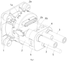
- Figure 1 shows an illustrative perspective view of a charging seat according to an exemplary embodiment of the present invention
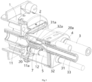
- Figure 2 shows a cross-sectional view of a charging seat according to an exemplary embodiment of the present invention, in which the thermal conductive component 7 is shown
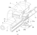
- Figure 3 shows a cross-sectional view of a charging seat according to an exemplary embodiment of the present invention, which illustrates the cooling core pipe 31 of the charging cable 3 and the cooling core pipe joint 20a of the cooling chamber 20
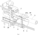
- Figure 4 shows a cross-sectional view of a charging seat according to an exemplary embodiment of the present invention, showing the inlet pipe joint 20b of the inlet pipe 4 and the cooling chamber 20
- Figure 5 shows a cross-sectional view of a charging seat according to an exemplary embodiment of the present invention, which illustrates the cooling core pipe 32 of the charging cable 3, the cooling core pipe joint 20a of the cooling chamber 20, the inlet tube 4, and the inlet tube joint 20b of the cooling chamber 20.
- a rear housing 2 for a charging seat is disclosed.
- a cooling chamber 20 is formed in the rear housing 2 of the charging seat, which has an inlet pipe joint 20b for connecting with the inlet pipe 4 and a cooling core pipe joint 20a for connecting with the cooling core pipe 32 of the charging cable 3, so that the cooling liquid can flow through the cooling chamber 20 of the rear housing 2 of the charging seat and the cooling core pipe 32 of the charging cable 3 to cool the interior of the charging seat and the charging cable 3.
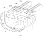
- Figure 6 shows a cross-sectional view of the rear housing 2 of a charging seat according to an exemplary embodiment of the present invention, which illustrates the cooling core pipe 32 of the charging cable 3, the cooling core pipe joint 20a of the cooling chamber 20, the inlet tube 4, and the inlet tube joint 20b of the cooling chamber 20;
- Figure 7 shows a cross-sectional view of the rear housing 2 of a charging seat according to an exemplary embodiment of the present invention, which illustrates the cooling core pipe 32 of the charging cable 3, the cooling core pipe joint 20a of the cooling chamber 20, and the thermal conductive component 7;
- Figure 8 shows a cross-sectional view of the rear housing 2 according to an exemplary embodiment of the present invention, wherein the inlet pipe 4 and the inlet pipe joint 20b of the cooling chamber 20 are shown;
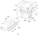
- Figure 9 shows an illustrative exploded view of the rear housing 2, charging cable 3, and inlet pipe 4 according to an exemplary embodiment of the present invention.
- the cooling chamber 20 has at least two cooling core pipe joints 20a, which are used to connect with the cooling core pipes 32 of at least two charging cables 3 respectively, so that the cooling liquid can flow through the cooling core pipes 32 of at least two charging cables 3 simultaneously to cool at least two charging cables 3 simultaneously.
- the cooling chamber 20 has two cooling core pipe joints 20a, which are arranged on both sides of the inlet pipe joint 20b and spaced apart from the inlet pipe joint 20b by a predetermined distance.
- a charging seat is also disclosed.
- the charging seat includes: a front housing 1, a rear housing 2, a charging terminal 11, and a charging cable 3.
- the rear housing 2 is assembled onto the rear end of the front housing 1.
- the charging terminal 11 is provided in the front housing 1 of the charging seat and its rear end 11a extends into the inner cavity of the rear housing 2 of the charging seat.
- the charging cable 3 extends into the inner cavity of the charging seat's rear housing 2 and is electrically connected to the rear end 11a of the charging terminal 11.
- the charging cable 3 includes a conductor 31 and a cooling core pipe 32.
- the front end 31a of the conductor 31 is electrically connected to the rear end 11a of the charging terminal 11.
- the cooling core pipe 32 is connected to the cooling core pipe joint 20a of the cooling chamber 20 of the rear housing 2, so that the cooling liquid can flow through the cooling chamber 20 of the rear housing 2 and the cooling core pipe 32 of the charging cable 3.
- the conductor 31 of the charging cable 3 is tubular, the cooling core pipe 32 is provided in the conductor 31, and the charging cable 3 also includes an outer insulation layer 33 wrapped around the outside of the conductor 31.
- the charging seat further comprises a thermal conductive component 7, which is arranged in the inner cavity of the rear housing 2 of the charging seat and is in physical contact with the rear end 11a of the charging terminal 11 and the outer wall surface of the cooling chamber 20, to transfer the heat of the rear end 11a of the charging terminal 11 to the cooling chamber 20.
- the front end 31a of the conductor 31 and the rear end 11a of the charging terminal 11 are wrapped in the thermal conductive component 7 and in thermal contact with the inner surface of the thermal conductive component 7, and the outer surface of the thermal conductive component 7 is in thermal contact with the outer wall surface of the cooling chamber 20.
- the thermal conductive component 7 has a pair of flat inner surfaces and a pair of flat outer surfaces that are opposite in the thickness direction of the rear end 11a of the charging terminal 11.
- the pair of flat inner surfaces of the thermal conductive component 7 are in thermal contact with the front end 31a of the conductor 31 and the rear end 11a of the charging terminal 11, respectively.
- One of the pair of flat outer surfaces of the thermal conductive component 7 is in thermal contact with the outer wall surface of the cooling chamber 20.
- the charging seat includes multiple charging terminals 11, multiple charging cables 3, and multiple thermal conductive components 7.
- the multiple charging terminals 11 are electrically connected to the multiple charging cables 3, respectively, and are thermally connected to the outer wall surface of the cooling chamber 20 through a corresponding thermal conductive component 7.
- multiple first snap slots 2a are formed on the peripheral wall of the front end of the rear housing 2, and the multiple first snap slots 2a are distributed at intervals in the circumferential direction of the rear housing 2.
- Multiple first protrusions 1a are formed on the rear end of the rear housing 2, which are respectively engaged with multiple first snap slots 2a to fix the front end of the rear housing 2 to the rear end of the front housing 1.
- the charging seat further comprises a signal terminal 12 and a signal cable 5.
- the signal terminal 12 is provided in the front housing 1 of the charging seat and its rear end extends into the rear housing 2 of the charging seat.
- One end of signal cable 5 extends into the charging seat's rear housing 2 and is electrically connected to the rear end of signal terminal 12.
- the charging seat further includes a rear cover 6, which is installed on the rear port of the rear housing 2 to cover the rear port of the rear housing 2.
- a first through-hole is formed in the rear cover 6 to allow the charging cable 3 to pass through
- a second through-hole is formed in the rear cover 6 to allow the signal cable 5 to pass through
- a third through-hole is formed in the rear cover 6 to allow the inlet pipe joint 20b to pass through.
- multiple second protrusions 2b are formed on the rear end of the rear housing 2, and the multiple second protrusions 2b are distributed at intervals in the circumferential direction of the rear housing 2.
- Multiple second snap slots 6b are formed on the rear cover 6, which are respectively engaged with multiple second protrusions 2b to fix the rear cover 6 to the rear end of the rear housing 2.
- the charging seat further comprises a sealing element 8, which is installed in the rear port of the rear housing 2 for sealing the rear port of the rear housing 2.
- the charging cable 3, signal cable 5, and inlet pipe joint 20b pass through the seal element 8, and the rear cover 6 is pressed against the seal element 8 to position seal element 8 in the rear port of rear housing 2.
- the charging seat further includes an inlet pipe 4, and one end 4b of the inlet pipe 4 is connected to the inlet pipe joint 20b for inputting the cooling liquid into the cooling chamber 20.
- the cooling chamber 20 also has a discharge port 201.
- the charging seat also includes a sealing plug 21 and a sealing ring 22.
- the sealing plug 21 is inserted into the discharge port 201.
- the seal ring 22 is fitted onto the seal plug 21.
- the sealing ring 22 is compressed between the sealing plug 21 and the inner wall of the discharge port 201 to achieve sealing between the two.
Landscapes
- Engineering & Computer Science (AREA)
- Power Engineering (AREA)
- Transportation (AREA)
- Mechanical Engineering (AREA)
- Electric Propulsion And Braking For Vehicles (AREA)
- Connector Housings Or Holding Contact Members (AREA)
Abstract
The present invention discloses a rear housing for a charging seat and a charging seat. A cooling chamber (20) is formed in the rear housing (2) of the charging seat, the cooling chamber (20) has an inlet pipe joint (20b) for connecting with an inlet pipe (4) and a cooling core pipe joint (20a) for connecting with a cooling core pipe (32) of a charging cable (3), so that the cooling liquid can flow through the cooling chamber (20) of the rear housing (2) of the charging seat and the cooling core pipe (32) of the charging cable (3) to cool the interior of the charging seat and the charging cable (3). In the present invention, the cooling chamber in the rear housing of the charging seat connects the cooling core pipe of the charging cable to the cooling circuit, allowing the cooling liquid to flow through the cooling chamber of the rear housing of the charging seat and the cooling core pipe of the charging cable, thereby enabling sufficient cooling of the interior of the charging seat and the charging cable. In addition, in some embodiments of the present invention, the thermal conductive component in the charging seat can quickly transfer the heat from the charging terminal to the cooling chamber, thereby improving the cooling effect of the charging seat.
Description
- This application claims the benefit of Chinese Patent Application No.
CN202323197523.3 filed on November 24, 2023 - The present invention relates to a rear housing for a charging seat and a charging seat comprising the rear housing.
- In the prior art, the charging seat usually includes a housing, a charging terminal set in the housing, and a charging cable electrically connected to the charging terminal. In order to improve the charging speed, it is necessary to increase the charging current. Currently, the charging current requirement is as high as 600A, and it may be further increased to 1000A in the future. When this high current flows through the charging cable and charging terminal, it will cause a sharp rise in the temperature inside the housing and the temperature of the charging cable. In order to prevent excessive temperature rise, in existing technology, the diameter of the charging cable is usually increased, but this will increase the volume and weight of the charging seat product, and lead to higher costs.
- The present invention has been made to overcome or alleviate at least one aspect of the above mentioned disadvantages.
- According to an aspect of the present invention, there is provided a rear housing for a charging seat. A cooling chamber is formed in the rear housing of the charging seat, the cooling chamber has an inlet pipe joint for connecting with an inlet pipe and a cooling core pipe joint for connecting with a cooling core pipe of a charging cable, so that the cooling liquid can flow through the cooling chamber of the rear housing of the charging seat and the cooling core pipe of the charging cable to cool the interior of the charging seat and the charging cable.
- According to an exemplary embodiment of the present invention, the cooling chamber has at least two cooling core pipe joints, which are used to connect with the cooling core pipes of at least two charging cables respectively, so that the cooling liquid can flow through the cooling core pipes of the at least two charging cables simultaneously to cool the at least two charging cables.
- According to another exemplary embodiment of the present invention, the cooling chamber has two cooling core pipe joints, which are arranged on both sides of the inlet pipe joint and spaced apart from the inlet pipe joint by a predetermined distance.
- According to another aspect of the present invention, there is provided a charging seat. The charging seat comprises of: a front housing; the above rear housing assembled onto the rear end of the front housing; a charging terminal which is provided in the front housing of the charging seat and its rear end extends into the inner cavity of the rear housing of the charging seat; and a charging cable which is inserted into the inner cavity of the rear housing of the charging seat and electrically connected to the rear end of the charging terminal. The charging cable comprises a conductor and a cooling core pipe, the front end of the conductor is electrically connected to the rear end of the charging terminal, and the cooling core pipe is connected to the cooling core pipe joint of the cooling chamber of the rear housing, so that the cooling liquid can flow through the cooling chamber of the rear housing and the cooling core pipe of the charging cable.
- According to an exemplary embodiment of the present invention, the conductor of the charging cable is tubular, and the cooling core pipe is provided in the conductor, the charging cable also includes an outer insulation layer wrapped around the outside of the conductor.
- According to another exemplary embodiment of the present invention, the front end of the conductor of the charging cable and the rear end of the charging terminal are flat and welded together.
- According to another exemplary embodiment of the present invention, the charging seat further comprises a thermal conductive component which is installed in the inner cavity of the rear housing of the charging seat and is in physical contact with both the rear end of the charging terminal and the outer wall surface of the cooling chamber to transfer heat from the rear end of the charging terminal to the cooling chamber.
- According to another exemplary embodiment of the present invention, the front end of the conductor and the rear end of the charging terminal are wrapped in the thermal conductive component and in thermal contact with the inner surface of the thermal conductive component, and the outer surface of the thermal conductive component is in thermal contact with the outer wall surface of the cooling chamber.
- According to another exemplary embodiment of the present invention, the thermal conductive component has a pair of flat inner surfaces and a pair of flat outer surfaces that are opposite in the thickness direction of the rear end of the charging terminal; the pair of flat inner surfaces of the thermal conductive component are in thermal contact with the front end of the conductor and the rear end of the charging terminal, respectively; one of the pair of flat outer surfaces of the thermal conductive component is in thermal contact with the outer wall surface of the cooling chamber.
- According to another exemplary embodiment of the present invention, the charging seat comprises multiple charging terminals, multiple charging cables, and multiple thermal conductive components, the multiple charging terminals are electrically connected to the multiple charging cables, respectively, and are thermally connected to the outer wall surface of the cooling chamber through a corresponding thermal conductive component.
- According to another exemplary embodiment of the present invention, multiple first snap slots are formed on the peripheral wall of the front end of the rear housing, and the multiple first snap slots are distributed at intervals in the circumferential direction of the rear housing; multiple first protrusions are formed on the rear end of the rear housing, and the multiple first protrusions are respectively engaged with the multiple first snap slots to fix the front end of the rear housing to the rear end of the front housing.
- According to another exemplary embodiment of the present invention, the charging seat further comprises of: a signal terminal which is provided in the front housing of the charging seat and its rear end extends into the rear housing of the charging seat; and a signal cable, one end of which extends into the rear housing of the charging seat and is electrically connected to the rear end of the signal terminal.
- According to another exemplary embodiment of the present invention, the charging seat further comprises a rear cover which is installed on the rear port of the rear housing to cover the rear port of the rear housing. A first through-hole allowing the charging cable to pass through, a second through-hole allowing the signal cable to pass through, and a third through-hole allowing the inlet pipe joint to pass through are formed in the rear cover.
- According to another exemplary embodiment of the present invention, multiple second protrusions are formed on the rear end of the charging seat housing, and the multiple second protrusions are distributed at intervals in the circumferential direction of the charging seat housing; multiple second snap slots are formed on the rear cover, and the multiple second snap slots are respectively engaged with the multiple second protrusions to fix the rear cover to the rear end of the rear housing.
- According to another exemplary embodiment of the present invention, the charging seat further comprises a sealing element which is installed in the rear port of the rear housing to seal the rear port of the rear housing. The charging cable, the signal cable, and the inlet pipe joint pass through the sealing element, and the rear cover is pressed against the sealing element to position the sealing element in the rear port of the rear housing.
- According to another exemplary embodiment of the present invention, the charging seat further comprises an inlet pipe, one end of which is connected to the inlet pipe joint, is used to input the cooling liquid into the cooling chamber.
- According to another exemplary embodiment of the present invention, the cooling chamber also has a discharge port. The charging seat further comprises of: a sealing plug which is inserted into the discharge port; and a sealing ring which is fitted onto the sealing plug. The sealing ring is compressed between the sealing plug and the inner wall of the discharge port to achieve sealing between the two.
- In the aforementioned exemplary embodiments according to the present invention, the cooling chamber in the rear housing of the charging seat connects the cooling core pipe of the charging cable to the cooling circuit, so that the cooling liquid can flow through the cooling chamber of the rear housing of the charging seat and the cooling core pipe of the charging cable, thereby enabling sufficient cooling of the interior of the charging seat and the charging cable.
- In addition, in the aforementioned exemplary embodiments according to the present invention, the thermal conductive component in the charging seat can quickly transfer the heat from the charging terminal to the cooling chamber, thereby improving the cooling effect of the charging seat.
- The above and other features of the present invention will become more apparent by describing in detail exemplary embodiments thereof with reference to the accompanying drawings, in which:
-
Figure 1 shows an illustrative perspective view of a charging seat according to an exemplary embodiment of the present invention; -
Figure 2 shows a cross-sectional view of a charging seat according to an exemplary embodiment of the present invention, in which a thermal conductive component is shown; -
Figure 3 shows a cross-sectional view of a charging seat according to an exemplary embodiment of the present invention, wherein the cooling core pipe of the charging cable and the cooling core pipe joint of the cooling chamber are shown; -
Figure 4 shows a cross-sectional view of a charging seat according to an exemplary embodiment of the present invention, showing the inlet pipe joint of the inlet pipe and the cooling chamber; -
Figure 5 shows a cross-sectional view of a charging seat according to an exemplary embodiment of the present invention, which illustrates the cooling core pipe of the charging cable, the cooling core pipe joint of the cooling chamber, the inlet pipe, and the inlet pipe joint of the cooling chamber; -
Figure 6 shows a cross-sectional view of the rear housing of a charging seat according to an exemplary embodiment of the present invention, which illustrates the cooling core pipe of the charging cable, the cooling core pipe joint of the cooling chamber, the inlet pipe, and the inlet pipe joint of the cooling chamber; -
Figure 7 shows a cross-sectional view of the rear housing of a charging seat according to an exemplary embodiment of the present invention, which illustrates the cooling core pipe of the charging cable, the cooling core pipe joint of the cooling chamber, and the thermal conductive component; -
Figure 8 shows a cross-sectional view of the rear housing of the charging seat according to an exemplary embodiment of the present invention, wherein the inlet pipe joint of the inlet pipe and the cooling chamber is shown; and -
Figure 9 shows an illustrative exploded view of the rear housing, charging cable, and inlet pipe according to an exemplary embodiment of the present invention. - Exemplary embodiments of the present disclosure will be described hereinafter in detail with reference to the attached drawings, wherein the like reference numerals refer to the like elements. The present disclosure may, however, be embodied in many different forms and should not be construed as being limited to the embodiment set forth herein; rather, these embodiments are provided so that the present disclosure will be thorough and complete, and will fully convey the concept of the disclosure to those skilled in the art.
- In the following detailed description, for purposes of explanation, numerous specific details are set forth in order to provide a thorough understanding of the disclosed embodiments. It will be apparent, however, that one or more embodiments may be practiced without these specific details. In other instances, well-known structures and devices are schematically shown in order to simplify the drawing.
- According to a general concept of the present invention, there is provided a rear housing for a charging seat. A cooling chamber is formed in the rear housing of the charging seat, the cooling chamber has an inlet pipe joint for connecting with an inlet pipe and a cooling core pipe joint for connecting with a cooling core pipe of a charging cable, so that the cooling liquid can flow through the cooling chamber of the rear housing of the charging seat and the cooling core pipe of the charging cable to cool the interior of the charging seat and the charging cable.
- According to another general concept of the present invention, there is provided a charging seat. The charging seat comprises of: a front housing; the above rear housing assembled onto the rear end of the front housing; a charging terminal which is provided in the front housing of the charging seat and its rear end extends into the inner cavity of the rear housing of the charging seat; and a charging cable which is inserted into the inner cavity of the rear housing of the charging seat and electrically connected to the rear end of the charging terminal. The charging cable comprises a conductor and a cooling core pipe, the front end of the conductor is electrically connected to the rear end of the charging terminal, and the cooling core pipe is connected to the cooling core pipe joint of the cooling chamber of the rear housing, so that the cooling liquid can flow through the cooling chamber of the rear housing and the cooling core pipe of the charging cable.
-
Figure 1 shows an illustrative perspective view of a charging seat according to an exemplary embodiment of the present invention;Figure 2 shows a cross-sectional view of a charging seat according to an exemplary embodiment of the present invention, in which the thermalconductive component 7 is shown;Figure 3 shows a cross-sectional view of a charging seat according to an exemplary embodiment of the present invention, which illustrates thecooling core pipe 31 of thecharging cable 3 and the coolingcore pipe joint 20a of thecooling chamber 20;Figure 4 shows a cross-sectional view of a charging seat according to an exemplary embodiment of the present invention, showing theinlet pipe joint 20b of theinlet pipe 4 and thecooling chamber 20;Figure 5 shows a cross-sectional view of a charging seat according to an exemplary embodiment of the present invention, which illustrates thecooling core pipe 32 of thecharging cable 3, the coolingcore pipe joint 20a of thecooling chamber 20, theinlet tube 4, and theinlet tube joint 20b of thecooling chamber 20. - As shown in
Figures 1 to 5 , in an exemplary embodiment of the present invention, arear housing 2 for a charging seat is disclosed. Acooling chamber 20 is formed in therear housing 2 of the charging seat, which has aninlet pipe joint 20b for connecting with theinlet pipe 4 and a coolingcore pipe joint 20a for connecting with thecooling core pipe 32 of thecharging cable 3, so that the cooling liquid can flow through thecooling chamber 20 of therear housing 2 of the charging seat and the coolingcore pipe 32 of thecharging cable 3 to cool the interior of the charging seat and thecharging cable 3. -
Figure 6 shows a cross-sectional view of therear housing 2 of a charging seat according to an exemplary embodiment of the present invention, which illustrates thecooling core pipe 32 of thecharging cable 3, the coolingcore pipe joint 20a of thecooling chamber 20, theinlet tube 4, and theinlet tube joint 20b of thecooling chamber 20;Figure 7 shows a cross-sectional view of therear housing 2 of a charging seat according to an exemplary embodiment of the present invention, which illustrates thecooling core pipe 32 of thecharging cable 3, the coolingcore pipe joint 20a of thecooling chamber 20, and the thermalconductive component 7;Figure 8 shows a cross-sectional view of therear housing 2 according to an exemplary embodiment of the present invention, wherein theinlet pipe 4 and theinlet pipe joint 20b of thecooling chamber 20 are shown;Figure 9 shows an illustrative exploded view of therear housing 2,charging cable 3, andinlet pipe 4 according to an exemplary embodiment of the present invention. - As shown in
Figure 1 to Figure 9 , in the illustrated embodiment, the coolingchamber 20 has at least two coolingcore pipe joints 20a, which are used to connect with thecooling core pipes 32 of at least two chargingcables 3 respectively, so that the cooling liquid can flow through thecooling core pipes 32 of at least two chargingcables 3 simultaneously to cool at least two chargingcables 3 simultaneously. - As shown in
Figure 1 to Figure 9 , in the illustrated embodiment, the coolingchamber 20 has two coolingcore pipe joints 20a, which are arranged on both sides of the inlet pipe joint 20b and spaced apart from the inlet pipe joint 20b by a predetermined distance. - As shown in
Figures 1 to 9 , in another exemplary embodiment of the present invention, a charging seat is also disclosed. The charging seat includes: afront housing 1, arear housing 2, a chargingterminal 11, and a chargingcable 3. Therear housing 2 is assembled onto the rear end of thefront housing 1. The chargingterminal 11 is provided in thefront housing 1 of the charging seat and itsrear end 11a extends into the inner cavity of therear housing 2 of the charging seat. The chargingcable 3 extends into the inner cavity of the charging seat'srear housing 2 and is electrically connected to therear end 11a of the chargingterminal 11. The chargingcable 3 includes aconductor 31 and acooling core pipe 32. Thefront end 31a of theconductor 31 is electrically connected to therear end 11a of the chargingterminal 11. The coolingcore pipe 32 is connected to the cooling core pipe joint 20a of the coolingchamber 20 of therear housing 2, so that the cooling liquid can flow through the coolingchamber 20 of therear housing 2 and thecooling core pipe 32 of the chargingcable 3. - As shown in
Figures 1 to 9 , in the illustrated embodiment, theconductor 31 of the chargingcable 3 is tubular, the coolingcore pipe 32 is provided in theconductor 31, and the chargingcable 3 also includes anouter insulation layer 33 wrapped around the outside of theconductor 31. - As shown in
Figures 1 to 9 , in the illustrated embodiment, thefront end 31a of theconductor 31 of the chargingcable 3 and therear end 11a of the chargingterminal 11 are flat and welded together;
As shown inFigures 1 to 9 , in the illustrated embodiment, the charging seat further comprises a thermalconductive component 7, which is arranged in the inner cavity of therear housing 2 of the charging seat and is in physical contact with therear end 11a of the chargingterminal 11 and the outer wall surface of the coolingchamber 20, to transfer the heat of therear end 11a of the chargingterminal 11 to the coolingchamber 20. - As shown in
Figure 1 to Figure 9 , in the illustrated embodiment, thefront end 31a of theconductor 31 and therear end 11a of the chargingterminal 11 are wrapped in the thermalconductive component 7 and in thermal contact with the inner surface of the thermalconductive component 7, and the outer surface of the thermalconductive component 7 is in thermal contact with the outer wall surface of the coolingchamber 20. - As shown in
Figures 1 to 9 , in the illustrated embodiment, the thermalconductive component 7 has a pair of flat inner surfaces and a pair of flat outer surfaces that are opposite in the thickness direction of therear end 11a of the chargingterminal 11. The pair of flat inner surfaces of the thermalconductive component 7 are in thermal contact with thefront end 31a of theconductor 31 and therear end 11a of the chargingterminal 11, respectively. One of the pair of flat outer surfaces of the thermalconductive component 7 is in thermal contact with the outer wall surface of the coolingchamber 20. - As shown in
Figures 1 to 9 , in the illustrated embodiment, the charging seat includesmultiple charging terminals 11,multiple charging cables 3, and multiple thermalconductive components 7. Themultiple charging terminals 11 are electrically connected to themultiple charging cables 3, respectively, and are thermally connected to the outer wall surface of the coolingchamber 20 through a corresponding thermalconductive component 7. - As shown in
Figures 1 to 9 , in the illustrated embodiment, multiplefirst snap slots 2a are formed on the peripheral wall of the front end of therear housing 2, and the multiplefirst snap slots 2a are distributed at intervals in the circumferential direction of therear housing 2. Multiplefirst protrusions 1a are formed on the rear end of therear housing 2, which are respectively engaged with multiplefirst snap slots 2a to fix the front end of therear housing 2 to the rear end of thefront housing 1. - As shown in
Figures 1 to 9 , in the illustrated embodiment, the charging seat further comprises asignal terminal 12 and asignal cable 5. Thesignal terminal 12 is provided in thefront housing 1 of the charging seat and its rear end extends into therear housing 2 of the charging seat. One end ofsignal cable 5 extends into the charging seat'srear housing 2 and is electrically connected to the rear end ofsignal terminal 12. - As shown in
Figures 1 to 9 , in the illustrated embodiment, the charging seat further includes arear cover 6, which is installed on the rear port of therear housing 2 to cover the rear port of therear housing 2. A first through-hole is formed in therear cover 6 to allow the chargingcable 3 to pass through, a second through-hole is formed in therear cover 6 to allow thesignal cable 5 to pass through, and a third through-hole is formed in therear cover 6 to allow the inlet pipe joint 20b to pass through. - As shown in
Figures 1 to 9 , in the illustrated embodiment, multiplesecond protrusions 2b are formed on the rear end of therear housing 2, and the multiplesecond protrusions 2b are distributed at intervals in the circumferential direction of therear housing 2. Multiple second snap slots 6b are formed on therear cover 6, which are respectively engaged with multiplesecond protrusions 2b to fix therear cover 6 to the rear end of therear housing 2. - As shown in
Figures 1 to 9 , in the illustrated embodiment, the charging seat further comprises a sealing element 8, which is installed in the rear port of therear housing 2 for sealing the rear port of therear housing 2. The chargingcable 3,signal cable 5, and inlet pipe joint 20b pass through the seal element 8, and therear cover 6 is pressed against the seal element 8 to position seal element 8 in the rear port ofrear housing 2. - As shown in
Figures 1 to 9 , in the illustrated embodiment, the charging seat further includes aninlet pipe 4, and oneend 4b of theinlet pipe 4 is connected to the inlet pipe joint 20b for inputting the cooling liquid into the coolingchamber 20. - As shown in
Figures 1 to 9 , in the illustrated embodiment, the coolingchamber 20 also has adischarge port 201. The charging seat also includes a sealingplug 21 and a sealingring 22. The sealingplug 21 is inserted into thedischarge port 201. Theseal ring 22 is fitted onto theseal plug 21. The sealingring 22 is compressed between the sealingplug 21 and the inner wall of thedischarge port 201 to achieve sealing between the two. - It should be appreciated for those skilled in this art that the above embodiments are intended to be illustrated, and not restrictive. For example, many modifications may be made to the above embodiments by those skilled in this art, and various features described in different embodiments may be freely combined with each other without conflicting in configuration or principle.
- Although several exemplary embodiments have been shown and described, it would be appreciated by those skilled in the art that various changes or modifications may be made in these embodiments without departing from the principles and spirit of the disclosure, the scope of which is defined in the claims and their equivalents.
- As used herein, an element recited in the singular and proceeded with the word "a" or "an" should be understood as not excluding plural of said elements or steps, unless such exclusion is explicitly stated. Furthermore, references to "one embodiment" of the present invention are not intended to be interpreted as excluding the existence of additional embodiments that also incorporate the recited features. Moreover, unless explicitly stated to the contrary, embodiments "comprising" or "having" an element or a plurality of elements having a particular property may include additional such elements not having that property.
Claims (17)
- A rear housing for a charging seat,
wherein a cooling chamber (20) is formed in the rear housing (2) of the charging seat, the cooling chamber (20) has an inlet pipe joint (20b) for connecting with an inlet pipe (4) and a cooling core pipe joint (20a) for connecting with a cooling core pipe (32) of a charging cable (3), so that the cooling liquid can flow through the cooling chamber (20) of the rear housing (2) of the charging seat and the cooling core pipe (32) of the charging cable (3) to cool the interior of the charging seat and the charging cable (3). - The rear housing according to claim 1,
wherein the cooling chamber (20) has at least two cooling core pipe joints (20a), which are used to connect with the cooling core pipes (32) of at least two charging cables (3) respectively, so that the cooling liquid can flow through the cooling core pipes (32) of the at least two charging cables (3) simultaneously to cool the at least two charging cables (3). - The rear housing according to claim 1,
wherein the cooling chamber (20) has two cooling core pipe joints (20a), which are arranged on both sides of the inlet pipe joint (20b) and spaced apart from the inlet pipe joint (20b) by a predetermined distance. - A charging seat, comprising:a front housing (1);the rear housing (2) according to any one of claims 1-3, assembled onto the rear end of the front housing (1);a charging terminal (11) which is provided in the front housing (1) of the charging seat and its rear end (1 1a) extends into the inner cavity of the rear housing (2) of the charging seat; anda charging cable (3) which is inserted into the inner cavity of the rear housing (2) of the charging seat and electrically connected to the rear end (11a) of the charging terminal (11),wherein the charging cable (3) comprises a conductor (31) and a cooling core pipe (32), the front end (31a) of the conductor (31) is electrically connected to the rear end (11a) of the charging terminal (11), and the cooling core pipe (32) is connected to the cooling core pipe joint (20a) of the cooling chamber (20) of the rear housing (2), so that the cooling liquid can flow through the cooling chamber (20) of the rear housing (2) and the cooling core pipe (32) of the charging cable (3).
- The charging seat according to claim 4,
wherein the conductor (31) of the charging cable (3) is tubular, and the cooling core pipe (32) is provided in the conductor (31), the charging cable (3) also includes an outer insulation layer (33) wrapped around the outside of the conductor (31). - The charging seat according to claim 4,
wherein the front end (31a) of the conductor (31) of the charging cable (3) and the rear end (11a) of the charging terminal (11) are flat and welded together. - The charging seat according to claim 4, further comprising:
a thermal conductive component (7) which is installed in the inner cavity of the rear housing (2) of the charging seat and is in physical contact with both the rear end (11a) of the charging terminal (11) and the outer wall surface of the cooling chamber (20) to transfer heat from the rear end (11a) of the charging terminal (11) to the cooling chamber (20). - The charging seat according to claim 7,
wherein the front end (31a) of the conductor (31) and the rear end (11a) of the charging terminal (11) are wrapped in the thermal conductive component (7) and in thermal contact with the inner surface of the thermal conductive component (7), and the outer surface of the thermal conductive component (7) is in thermal contact with the outer wall surface of the cooling chamber (20). - The charging seat according to claim 8,wherein the thermal conductive component (7) has a pair of flat inner surfaces and a pair of flat outer surfaces that are opposite in the thickness direction of the rear end (11a) of the charging terminal (11);wherein the pair of flat inner surfaces of the thermal conductive component (7) are in thermal contact with the front end (31a) of the conductor (31) and the rear end (11a) of the charging terminal (11), respectively; one of the pair of flat outer surfaces of the thermal conductive component (7) is in thermal contact with the outer wall surface of the cooling chamber (20).
- The charging seat according to claim 7,wherein the charging seat comprises multiple charging terminals (11), multiple charging cables (3), and multiple thermal conductive components (7),wherein the multiple charging terminals (11) are electrically connected to the multiple charging cables (3), respectively, and are thermally connected to the outer wall surface of the cooling chamber (20) through a corresponding thermal conductive component (7).
- The charging seat according to claim 4,wherein multiple first snap slots (2a) are formed on the peripheral wall of the front end of the rear housing (2), and the multiple first snap slots (2a) are distributed at intervals in the circumferential direction of the rear housing (2);wherein multiple first protrusions (1a) are formed on the rear end of the rear housing (2), and the multiple first protrusions (1a) are respectively engaged with the multiple first snap slots (2a) to fix the front end of the rear housing (2) to the rear end of the front housing (1).
- The charging seat according to claim 4, further comprising:a signal terminal (12) which is provided in the front housing (1) of the charging seat and its rear end extends into the rear housing (2) of the charging seat; anda signal cable (5), one end of which extends into the rear housing (2) of the charging seat and is electrically connected to the rear end of the signal terminal (12).
- The charging seat according to claim 12, further comprising:a rear cover (6) which is installed on the rear port of the rear housing (2) to cover the rear port of the rear housing (2),wherein a first through-hole allowing the charging cable (3) to pass through, a second through-hole allowing the signal cable (5) to pass through, and a third through-hole allowing the inlet pipe joint (20b) to pass through are formed in the rear cover (6).
- The charging seat according to claim 13,wherein multiple second protrusions (2b) are formed on the rear end of the charging seat housing (2), and the multiple second protrusions (2b) are distributed at intervals in the circumferential direction of the charging seat housing (2);wherein multiple second snap slots (6b) are formed on the rear cover (6), and the multiple second snap slots (6b) are respectively engaged with the multiple second protrusions (2b) to fix the rear cover (6) to the rear end of the rear housing (2).
- The charging seat according to claim 13, further comprising:a sealing element (8) which is installed in the rear port of the rear housing (2) to seal the rear port of the rear housing (2),wherein the charging cable (3), the signal cable (5), and the inlet pipe joint (20b) pass through the sealing element (8), and the rear cover (6) is pressed against the sealing element (8) to position the sealing element (8) in the rear port of the rear housing (2).
- The charging seat according to claim 4, further comprising:
an inlet pipe (4), one end of which is connected to the inlet pipe joint (20b), is used to input the cooling liquid into the cooling chamber (20). - The charging seat according to any one of claims 4-16,wherein the cooling chamber (20) also has a discharge port (201),wherein the charging seat further comprises:a sealing plug (21) which is inserted into the discharge port (201); anda sealing ring (22) which is fitted onto the sealing plug (21),wherein the sealing ring (22) is compressed between the sealing plug (21) and the inner wall of the discharge port (201) to achieve sealing between the two.
Applications Claiming Priority (1)
| Application Number | Priority Date | Filing Date | Title |
|---|---|---|---|
| CN202323197523.3U CN221510097U (en) | 2023-11-24 | 2023-11-24 | Charging seat rear shell and charging seat |
Publications (1)
| Publication Number | Publication Date |
|---|---|
| EP4559731A1 true EP4559731A1 (en) | 2025-05-28 |
Family
ID=92122822
Family Applications (1)
| Application Number | Title | Priority Date | Filing Date |
|---|---|---|---|
| EP24214494.7A Pending EP4559731A1 (en) | 2023-11-24 | 2024-11-21 | Rear housing for charging seat and charging seat |
Country Status (4)
| Country | Link |
|---|---|
| EP (1) | EP4559731A1 (en) |
| JP (1) | JP2025085621A (en) |
| KR (1) | KR20250078341A (en) |
| CN (1) | CN221510097U (en) |
Citations (3)
| Publication number | Priority date | Publication date | Assignee | Title |
|---|---|---|---|---|
| DE102020132724A1 (en) * | 2020-12-09 | 2022-06-09 | Phoenix Contact E-Mobility Gmbh | Cooling module for a connector part and connector part |
| EP4068527A2 (en) * | 2019-11-27 | 2022-10-05 | LS EV Korea Ltd. | Electric vehicle charging connector and electric vehicle charging assembly comprising same |
| CN116061724A (en) * | 2023-01-06 | 2023-05-05 | 长春捷翼汽车科技股份有限公司 | Liquid cooling high-voltage connector |
-
2023
- 2023-11-24 CN CN202323197523.3U patent/CN221510097U/en active Active
-
2024
- 2024-11-20 JP JP2024202027A patent/JP2025085621A/en active Pending
- 2024-11-21 KR KR1020240167022A patent/KR20250078341A/en active Pending
- 2024-11-21 EP EP24214494.7A patent/EP4559731A1/en active Pending
Patent Citations (3)
| Publication number | Priority date | Publication date | Assignee | Title |
|---|---|---|---|---|
| EP4068527A2 (en) * | 2019-11-27 | 2022-10-05 | LS EV Korea Ltd. | Electric vehicle charging connector and electric vehicle charging assembly comprising same |
| DE102020132724A1 (en) * | 2020-12-09 | 2022-06-09 | Phoenix Contact E-Mobility Gmbh | Cooling module for a connector part and connector part |
| CN116061724A (en) * | 2023-01-06 | 2023-05-05 | 长春捷翼汽车科技股份有限公司 | Liquid cooling high-voltage connector |
Also Published As
| Publication number | Publication date |
|---|---|
| KR20250078341A (en) | 2025-06-02 |
| JP2025085621A (en) | 2025-06-05 |
| CN221510097U (en) | 2024-08-09 |
Similar Documents
| Publication | Publication Date | Title |
|---|---|---|
| US7964826B2 (en) | Modular heater systems | |
| US11852271B2 (en) | Modular heater systems | |
| CN110696651B (en) | A charging terminal liquid cooling structure | |
| CN220020708U (en) | Charging stand | |
| US12470009B2 (en) | Contact element for an EV connector with capillary fluid cooling | |
| KR20240161606A (en) | Electric connection member and electrical connection assembly | |
| KR20250078341A (en) | Rear housing for charging seat and charging seat | |
| EP4582301A1 (en) | Cooling device, cooling system and charging device | |
| EP4578718A1 (en) | Cooling device, cooling system and charging device | |
| EP4459800A1 (en) | Electric connection member and electric connection assembly | |
| KR20240173615A (en) | Charging seat | |
| CN219760011U (en) | Electrical connector and electrical connection assembly | |
| CN221575931U (en) | Cooling devices, cooling systems and charging devices | |
| EP4578714A1 (en) | Cooling module, electrical connection module and charging device | |
| CN219717298U (en) | Electrical connector and electrical connection assembly | |
| CN219554121U (en) | Electrical connection components and charging stand components | |
| CN224204524U (en) | Connector, electrical device and vehicle | |
| CN115051194B (en) | Connectors and electronic devices | |
| EP4574543A1 (en) | Charging terminal cooling box and charging seat | |
| EP4578713A1 (en) | Charging terminal fixing component, top cover assembly, charging terminal cooling box and charging seat | |
| US20260056080A1 (en) | Charging Dock | |
| CN223744016U (en) | An electrical connector and a connection device | |
| KR20250105223A (en) | Cooling module, electrical connection module and charging device | |
| CN110199147A (en) | Connecting body, fittings, hydraulic system and related installation method for fluid passage between two hydraulic circuits | |
| CN204558830U (en) | Antenna connector for easy assembly |
Legal Events
| Date | Code | Title | Description |
|---|---|---|---|
| PUAI | Public reference made under article 153(3) epc to a published international application that has entered the european phase |
Free format text: ORIGINAL CODE: 0009012 |
|
| STAA | Information on the status of an ep patent application or granted ep patent |
Free format text: STATUS: THE APPLICATION HAS BEEN PUBLISHED |
|
| AK | Designated contracting states |
Kind code of ref document: A1 Designated state(s): AL AT BE BG CH CY CZ DE DK EE ES FI FR GB GR HR HU IE IS IT LI LT LU LV MC ME MK MT NL NO PL PT RO RS SE SI SK SM TR |
|
| STAA | Information on the status of an ep patent application or granted ep patent |
Free format text: STATUS: REQUEST FOR EXAMINATION WAS MADE |
|
| 17P | Request for examination filed |
Effective date: 20251124 |