EP4559634A1 - Robot - Google Patents
Robot Download PDFInfo
- Publication number
- EP4559634A1 EP4559634A1 EP24210351.3A EP24210351A EP4559634A1 EP 4559634 A1 EP4559634 A1 EP 4559634A1 EP 24210351 A EP24210351 A EP 24210351A EP 4559634 A1 EP4559634 A1 EP 4559634A1
- Authority
- EP
- European Patent Office
- Prior art keywords
- link
- rotation axis
- sub
- actuator
- opening
- Prior art date
- Legal status (The legal status is an assumption and is not a legal conclusion. Google has not performed a legal analysis and makes no representation as to the accuracy of the status listed.)
- Granted
Links
Images





Classifications
-
- B—PERFORMING OPERATIONS; TRANSPORTING
- B25—HAND TOOLS; PORTABLE POWER-DRIVEN TOOLS; MANIPULATORS
- B25J—MANIPULATORS; CHAMBERS PROVIDED WITH MANIPULATION DEVICES
- B25J9/00—Program-controlled manipulators
- B25J9/0009—Constructional details, e.g. manipulator supports, bases
-
- B—PERFORMING OPERATIONS; TRANSPORTING
- B25—HAND TOOLS; PORTABLE POWER-DRIVEN TOOLS; MANIPULATORS
- B25J—MANIPULATORS; CHAMBERS PROVIDED WITH MANIPULATION DEVICES
- B25J18/00—Arms
- B25J18/02—Arms extensible
- B25J18/04—Arms extensible rotatable
-
- B—PERFORMING OPERATIONS; TRANSPORTING
- B25—HAND TOOLS; PORTABLE POWER-DRIVEN TOOLS; MANIPULATORS
- B25J—MANIPULATORS; CHAMBERS PROVIDED WITH MANIPULATION DEVICES
- B25J9/00—Program-controlled manipulators
- B25J9/10—Program-controlled manipulators characterised by positioning means for manipulator elements
-
- B—PERFORMING OPERATIONS; TRANSPORTING
- B25—HAND TOOLS; PORTABLE POWER-DRIVEN TOOLS; MANIPULATORS
- B25J—MANIPULATORS; CHAMBERS PROVIDED WITH MANIPULATION DEVICES
- B25J18/00—Arms
-
- B—PERFORMING OPERATIONS; TRANSPORTING
- B25—HAND TOOLS; PORTABLE POWER-DRIVEN TOOLS; MANIPULATORS
- B25J—MANIPULATORS; CHAMBERS PROVIDED WITH MANIPULATION DEVICES
- B25J19/00—Accessories fitted to manipulators, e.g. for monitoring, for viewing; Safety devices combined with or specially adapted for use in connection with manipulators
- B25J19/0025—Means for supplying energy to the end effector
- B25J19/0029—Means for supplying energy to the end effector arranged within the different robot elements
-
- B—PERFORMING OPERATIONS; TRANSPORTING
- B25—HAND TOOLS; PORTABLE POWER-DRIVEN TOOLS; MANIPULATORS
- B25J—MANIPULATORS; CHAMBERS PROVIDED WITH MANIPULATION DEVICES
- B25J19/00—Accessories fitted to manipulators, e.g. for monitoring, for viewing; Safety devices combined with or specially adapted for use in connection with manipulators
- B25J19/0075—Means for protecting the manipulator from its environment or vice versa
-
- B—PERFORMING OPERATIONS; TRANSPORTING
- B25—HAND TOOLS; PORTABLE POWER-DRIVEN TOOLS; MANIPULATORS
- B25J—MANIPULATORS; CHAMBERS PROVIDED WITH MANIPULATION DEVICES
- B25J9/00—Program-controlled manipulators
- B25J9/02—Program-controlled manipulators characterised by movement of the arms, e.g. cartesian coordinate type
- B25J9/04—Program-controlled manipulators characterised by movement of the arms, e.g. cartesian coordinate type by rotating at least one arm, excluding the head movement itself, e.g. cylindrical coordinate type or polar coordinate type
- B25J9/046—Revolute coordinate type
- B25J9/047—Revolute coordinate type the pivoting axis of the first arm being offset to the vertical axis
-
- B—PERFORMING OPERATIONS; TRANSPORTING
- B25—HAND TOOLS; PORTABLE POWER-DRIVEN TOOLS; MANIPULATORS
- B25J—MANIPULATORS; CHAMBERS PROVIDED WITH MANIPULATION DEVICES
- B25J9/00—Program-controlled manipulators
- B25J9/10—Program-controlled manipulators characterised by positioning means for manipulator elements
- B25J9/106—Program-controlled manipulators characterised by positioning means for manipulator elements with articulated links
-
- B—PERFORMING OPERATIONS; TRANSPORTING
- B25—HAND TOOLS; PORTABLE POWER-DRIVEN TOOLS; MANIPULATORS
- B25J—MANIPULATORS; CHAMBERS PROVIDED WITH MANIPULATION DEVICES
- B25J9/00—Program-controlled manipulators
- B25J9/10—Program-controlled manipulators characterised by positioning means for manipulator elements
- B25J9/108—Bearings specially adapted therefor
-
- B—PERFORMING OPERATIONS; TRANSPORTING
- B25—HAND TOOLS; PORTABLE POWER-DRIVEN TOOLS; MANIPULATORS
- B25J—MANIPULATORS; CHAMBERS PROVIDED WITH MANIPULATION DEVICES
- B25J9/00—Program-controlled manipulators
- B25J9/10—Program-controlled manipulators characterised by positioning means for manipulator elements
- B25J9/12—Program-controlled manipulators characterised by positioning means for manipulator elements electric
- B25J9/126—Rotary actuators
Definitions
- the present disclosure relates to a robot.
- Japanese Unexamined Patent Publication No. 2012-161868 discloses a robot including a base, a first structure, a second structure, and a third structure.
- the first structure is coupled to the base to be rotatable around a first axis.
- the second structure is coupled to the first structure to be rotatable around a second axis orthogonal to the first axis.
- the third structure is coupled to the second structure to be rotatable around a third axis parallel to the second axis.
- the second structure includes a main structural portion, an auxiliary structural portion, and a coupling portion that couples the main structural portion to the auxiliary structural portion.
- Each of the first structure and the third structure is sandwiched between the main structural portion and the auxiliary structural portion.
- the present disclosure provides a robot effective in reducing unevenness in an appearance and improving positioning accuracy.
- a robot includes a first link, a second link aligned with the first link along a rotation axis and extending away from the rotation axis, and an actuator accommodated in the first link to rotate the second link around the rotation axis with respect to the first link.
- the second link includes a first sub-link and a second sub-link that sandwich the actuator along the rotation axis, the first sub-link is attached to the actuator, and the second sub-link is attached to the first sub-link in a state where the second sub-link is not constrained from the first link in a direction crossing the rotation axis.
- the robot effective in reducing the unevenness in the appearance and improving the positioning accuracy is provided.
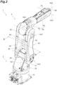
- FIGS. 1 and 2 illustrate a robot according to an embodiment.
- a robot 1 illustrated in FIG. 1 is a vertical articulated robot.
- the robot 1 automatically performs various works on a work object.
- the robot 1 is, for example, an industrial robot, and in one example, automatically executes various conveyance, machining, assembly, or the like on components or assemblies in production lines of products.
- the application of the robot 1 is not limited to industrial use.
- an outline of a structure of the robot 1 will be first described, and then details of some members included in the robot 1 will be described.
- the robot 1 includes a base portion 2 and an articulated arm 4.
- the base portion 2 is a portion that supports the articulated arm 4.
- the articulated arm 4 is attached to the base portion 2 in a state of being rotatable and includes serial link structures.
- the base portion 2 includes a base link 10 and a turning link 20.
- the base link 10 is also referred to as a base, and is fixed to an installation surface.
- the installation surface may be one surface forming a work area where a work by the robot 1 is performed.
- the installation surface is, for example, a bottom surface of the work area.
- the base link 10 may be fixed to a horizontal installation surface.
- the base link 10 may be fixed to an installation surface on a moving body such as an automatic guided vehicle (AGV).
- AGV automatic guided vehicle
- the turning link 20 is connected to the base link 10 to rotate (turn) around a rotation axis Ax1 (turning axis).
- the turning link 20 is attached to the base link 10 to be positioned above the base link 10, for example.
- the rotation axis Ax1 may be set to pass through the base link 10 and the turning link 20.
- the turning link 20 may be provided on the base link 10 to rotate around the vertical rotation axis Ax1.
- “upper” and “lower” are used to indicate an arrangement relationship when the structure of the robot 1 is described.
- “Upper” and “lower” mean “upper” and “lower” in a state where the rotation axis Ax1 is positioned vertically and the turning link 20 is positioned on the base link 10, but the base portion 2 may not necessarily be arranged in this manner.
- the base portion 2 may be arranged, for example, such that the turning link 20 is positioned below the base link 10 or such that the turning link 20 is positioned on a side of the base link 10.
- the base link 10 may be fixed to a wall surface of the work area or may be fixed to a ceiling surface of the work area.
- the articulated arm 4 includes, for example, an arm link 30, an arm link 60, an arm link 70, and a tool attachment portion 80.
- Each of the arm link 30, the arm link 60, and the arm link 70 is also simply referred to as an arm.
- the arm link 30 is connected to the turning link 20 to rotate around a rotation axis Ax2.
- the rotation axis Ax2 crosses, for example, the rotation axis Ax1. In the present disclosure, "crossing” also includes a skew relationship like a so-called grade separation.
- the arm link 30 may extend away from the rotation axis Ax2.
- the arm link 30 (second link) may be aligned with the turning link 20 (first link) along the rotation axis Ax2.
- the rotation axis Ax2 may be orthogonal to the rotation axis Ax1.
- the rotation axis Ax2 may be set to pass through a proximal end portion of the arm link 30 and the turning link 20.
- the arm link 60 is connected to the arm link 30 to rotate around a rotation axis Ax3 (second rotation axis) parallel to the rotation axis Ax2.
- the arm link 60 is connected to, for example, a distal end portion (end portion) of the arm link 30.
- the arm link 60 may extend away from the rotation axis Ax3.
- the arm link 60 (third link) may be aligned with the arm link 30 along the rotation axis Ax3.
- the rotation axis Ax3 may be set to pass through the distal end portion of the arm link 30 and a proximal end portion of the arm link 60.
- the arm link 60 includes an arm base portion 62 and a turning arm 64.
- the arm base portion 62 (third link) is a link connected to the distal end portion of the arm link 30 so as to rotate around the rotation axis Ax3.
- the arm base portion 62 may extend away from the rotation axis Ax3.
- the arm base portion 62 may be aligned with the arm link 30 along the rotation axis Ax3.
- the turning arm 64 (fourth link) is a link connected to the arm base portion 62 to rotate around a rotation axis Ax4 crossing the rotation axis Ax3.
- the turning arm 64 may extend from the arm base portion 62 along a direction in which the arm base portion 62 extends.
- the rotation axis Ax4 may be orthogonal to the rotation axis Ax3.
- the rotation axis Ax4 may be set to pass through the arm base portion 62 and the turning arm 64.
- the arm link 70 is connected to the arm link 60 to rotate around a rotation axis Ax5 crossing the rotation axis Ax4.
- the arm link 70 is attached to, for example, a distal end portion of the turning arm 64 of the arm link 60.
- the rotation axis Ax5 may be orthogonal to the rotation axis Ax4.
- the rotation axis Ax5 may be set to pass through the distal end portion of the turning arm 64 and the arm link 70.
- the tool attachment portion 80 is connected to the arm link 70 to rotate around a rotation axis Ax6 crossing the rotation axis Ax5.
- the rotation axis Ax6 may be orthogonal to the rotation axis Ax5.
- the rotation axis Ax6 may be set to pass through the arm link 70 and the tool attachment portion 80.
- a working tool is attached to the tool attachment portion 80.
- An example of the working tool is a suction nozzle configured to suck a workpiece, a hand configured to grip a workpiece, a welding torch, a screw tightening tool, or a polishing tool.
- the robot 1 includes an actuator 110, an actuator 120, an actuator 130, an actuator 140, an actuator 150, and an actuator 160.
- each actuator is schematically illustrated by a broken line in a simplified manner, and a diagram of each actuator is omitted in FIG. 2 .
- Each actuator may include a motor and a speed reducer.
- the actuator 110 rotates the turning link 20 around the rotation axis Ax1 with respect to the base link 10.
- the actuator 120 rotates the arm link 30 around the rotation axis Ax2 with respect to the turning link 20.
- the actuator 130 (second actuator) rotates the arm base portion 62 of the arm link 60 around the rotation axis Ax3 with respect to the arm link 30.
- the actuator 140 rotates the turning arm 64 of the arm link 60 around the rotation axis Ax4 with respect to the arm base portion 62.
- the actuator 150 rotates the arm link 70 around the rotation axis Ax5 with respect to the turning arm 64 of the arm link 60.
- the actuator 160 rotates the tool attachment portion 80 around the rotation axis Ax6 with respect to the arm link 70.
- the arm link 30 may include two sub-links. As illustrated in FIG. 1 or 2 , the arm link 30 may include a drive link 40 (link) and an auxiliary link 50 as two sub-links.
- the drive link 40 (first sub-link) and the auxiliary link 50 (second sub-link) may sandwich the actuator 120 along the rotation axis Ax2.
- the drive link 40, the actuator 120, and the auxiliary link 50 may be arranged in this order.
- the drive link 40 and the auxiliary link 50 may sandwich the actuator 130 along the rotation axis Ax3.
- the drive link 40, the actuator 130, and the auxiliary link 50 may be arranged in this order.
- the auxiliary link 50 may be made of a material (second material) having rigidity and specific gravity smaller than a material (first material) forming the drive link 40.
- the rigidity of the material forming the auxiliary link 50 may be smaller than the rigidity of the material forming the drive link 40, and the specific gravity of the material forming the auxiliary link 50 may be smaller than the specific gravity of the material forming the drive link 40.
- the material forming the drive link 40 is a material containing iron
- the material forming the auxiliary link 50 is a material containing aluminum.
- a thermal expansion coefficient linear expansion coefficient
- the drive link 40 is a link driven by the actuator 120. For example, a driving force by the actuator 120 is directly transmitted to the drive link 40.
- the drive link 40 may be connected to the turning link 20.
- the actuator 120 rotates the drive link 40 around the rotation axis Ax2 with respect to the turning link 20.
- FIG. 3 illustrates a section taken along line III-III drawn in FIG. 2 .
- the actuator 120 is connected to any portion of the drive link 40.
- the drive link 40 (second link) may be aligned with the turning link 20 (first link) along the rotation axis Ax2.
- the drive link 40 may extend away from the rotation axis Ax2.
- the actuator 120 may be accommodated in the turning link 20.
- the turning link 20 may include an internal space S2 and an opening 24 (see also FIG. 8 ).
- the internal space S2 is a space for accommodating the actuator 120. At least a part of the actuator 120 may be accommodated in the internal space S2.
- the turning link 20 includes a housing 21.
- the housing 21 is constituted by a wall forming the internal space S2.
- the opening 24 is an opening formed in the housing 21.
- the motor included in the actuator 120 is indicated by "122"
- the speed reducer included in the actuator 120 is indicated by "124".
- the motor 122 includes a motor body 122a and an output shaft 122b.
- the motor 122 rotates the drive link 40 around the rotation axis Ax2 with respect to the turning link 20.
- the motor 122 may be accommodated in the internal space S2 in the turning link 20.
- the motor 122 may be arranged such that the motor body 122a is accommodated in the internal space S2 in the turning link 20.
- the motor 122 may be installed such that the output shaft 122b is horizontal.
- the output shaft 122b of the motor 122 is connected to the speed reducer 124.
- an output shaft of the speed reducer 124 of the actuator 120 is connected to the drive link 40.
- the actuator 130 for driving the arm base portion 62 of the arm link 60 rotates the arm base portion 62 around the rotation axis Ax3 with respect to the drive link 40 of the arm link 30.
- the actuator 130 is connected to any portion of the drive link 40.
- a driving force by the actuator 130 is applied to the drive link 40, and thus, the arm base portion 62 rotates with respect to the drive link 40.
- the arm base portion 62 (second link) of the arm link 60 may be connected to an end portion of the drive link 40.
- the arm base portion 62 (second link) of the arm link 60 may be aligned with the drive link 40.
- the actuator 130 may be accommodated in the arm base portion 62 of the arm link 60.
- the arm base portion 62 of the arm link 60 may include an internal space S6 and an opening 66 (see also FIG. 10 ).
- the internal space S6 is a space for accommodating the actuator 130. At least a part of the actuator 130 may be accommodated in the internal space S6.
- the arm base portion 62 of the arm link 60 has a housing 65.
- the housing 65 is constituted by a wall forming the internal space S6.
- the opening 66 is an opening formed in the housing 65.
- the motor included in the actuator 130 is indicated by "132"
- the speed reducer included in the actuator 130 is indicated by "134”.
- the motor 132 includes a motor body 132a and an output shaft 132b.
- the motor 132 (second motor) rotates the arm base portion 62 around the rotation axis Ax3 with respect to the drive link 40.
- the motor 132 may be accommodated in the arm base portion 62.
- the motor 132 may be arranged such that the motor body 132a is accommodated in the internal space S6 in the arm base portion 62.
- the motor 132 may be installed such that the output shaft 132b is horizontal.
- the output shaft 132b of the motor 132 is connected to the speed reducer 134.
- an output shaft of the speed reducer 134 of the actuator 130 is connected to the drive link 40.
- FIG. 4 illustrates a perspective view of the drive link 40
- FIG. 5 illustrates a side view of the drive link 40 as viewed from a direction along the rotation axis Ax2.
- FIG. 6 is a schematic view in a case where a side surface of the drive link 40 is viewed from a direction orthogonal to a plane including the rotation axis Ax2 and the rotation axis Ax3.
- the drive link 40 is formed to extend over both the rotation axis Ax2 and the rotation axis Ax3.
- a direction in which the entire drive link 40 extends may be along a line segment connecting the rotation axis Ax2 and the rotation axis Ax3 at a shortest distance.
- the drive link 40 may be attached to the actuator 120.
- the drive link 40 may be attached to the actuator 130.
- the drive link 40 includes, for example, a connecting section 42, a connecting section 46, a link base section 44, and a reinforcing section 48. In a case where the drive link 40 is observed from the rotation axis Ax2 toward the rotation axis Ax3, the connecting section 42, the link base section 44, and the connecting section 46 are aligned in this order.
- the connecting section 42 is a portion connected to the actuator 120.
- the output shaft of the speed reducer 124 of the actuator 120 is connected to the connecting section 42.
- the connecting section 42 may include a connecting base section 42a and a surrounding wall 42b. A space for accommodating at least a part of the actuator 120 (for example, the speed reducer 124 of the actuator 120) is formed by the connecting base section 42a and the surrounding wall 42b.
- the connecting base section 42a is a portion connected to the actuator 120.
- the output shaft of the speed reducer 124 of the actuator 120 is connected to the connecting base section 42a.
- the connecting base section 42a may be formed to spread along a plane crossing the rotation axis Ax2.
- a thickness of the connecting base section 42a may not be constant, and at least a part of each of a pair of main surfaces of the connecting base section 42a may not be a plane.
- a shape of the connecting base section 42a may be circular as viewed from the rotation axis Ax2.
- the surrounding wall 42b is a portion protruding from the connecting base section 42a to surround at least a part of the actuator 120.
- the surrounding wall 42b is formed in an annular shape to surround at least a part of the speed reducer 124, for example.
- the surrounding wall 42b protrudes in a predetermined direction from an outer edge portion (outer edge and a portion in the vicinity thereof) of the connecting base section 42a.
- the surrounding wall 42b protrudes, for example, in an axial direction in which the rotation axis Ax2 extends.
- the connecting section 46 (second connecting section) is a portion connected to the actuator 130 (second actuator).
- the output shaft of the speed reducer 134 of the actuator 130 is connected to the connecting section 46.
- the connecting section 46 may include a connecting base section 46a (second connecting base section) and a surrounding wall 46b (second surrounding wall). A space for accommodating at least a part of the actuator 130 (for example, the speed reducer 134 of the actuator 130) is formed by the connecting base section 46a and the surrounding wall 46b.
- the connecting base section 46a is a portion connected to the actuator 130.
- the output shaft of the speed reducer 134 of the actuator 130 is connected to the connecting base section 46a.
- the connecting base section 46a may be formed to spread along the plane crossing the rotation axis Ax2.
- a thickness of at least a part of the connecting base section 46a may not be constant, and at least a part of each of a pair of main surfaces of the connecting base section 46a may not be a plane.
- a shape of the connecting base section 46a may be circular as viewed from the rotation axis Ax3.
- the surrounding wall 46b is a portion protruding from the connecting base section 46a to surround at least a part of the actuator 130.
- the surrounding wall 46b is formed in an annular shape to surround at least a part of the speed reducer 134, for example.
- the surrounding wall 46b protrudes in a predetermined direction from an outer edge portion (outer edge and a portion in the vicinity thereof) of the connecting base section 46a.
- the surrounding wall 46b protrudes, for example, in an axial direction in which the rotation axis Ax3 extends.
- the link base section 44 is a portion extending from the connecting section 42 while crossing the rotation axis Ax2.
- the link base section 44 is connected to the connecting section 46 and also crosses the rotation axis Ax3.
- the link base section 44 may be formed to spread along the plane crossing the rotation axis Ax2.
- a thickness of at least a part of the link base section 44 may not be constant, and at least a part of each of a pair of main surfaces of the link base section 44 may not be a plane.
- the link base section 44 is formed to extend along a virtual line segment connecting the rotation axis Ax2 and the rotation axis Ax3.
- the connecting base section 42a of the connecting section 42 is continued to the link base section 44, and the connecting base section 46a of the connecting section 46 is continued to the link base section 44.
- the connecting section 42 (the connecting base section 42a and the surrounding wall 42b), the link base section 44, and the connecting section 46 (the connecting base section 46a and the surrounding wall 46b) may be integrally formed.
- a direction orthogonal to a virtual straight line passing through the rotation axis Ax2 and the rotation axis Ax3 is defined as a "width direction" in the drive link 40.
- the link base section 44 is formed such that a size in the width direction decreases at a central portion between the rotation axis Ax2 and the rotation axis Ax3.
- the size of the link base section 44 in the width direction increases as it approaches the connecting section 42, starting from the central portion between the rotation axis Ax2 and the rotation axis Ax3.
- the size of the link base section 44 in the width direction increases as it approaches the connecting section 46, starting from the central portion between the rotation axis Ax2 and the rotation axis Ax3.
- the reinforcing section 48 is formed to increase rigidity while reducing a weight of the drive link 40.
- the reinforcing section 48 may be formed to protrude from the link base section 44 between the connecting section 42 and an end portion (an end portion close to the rotation axis Ax3) of the link base section 44.
- the reinforcing section 48 is formed integrally with the link base section 44 to protrude from the link base section 44 between the connecting section 42 and the connecting section 46.
- the reinforcing section 48 may protrude in the same direction as the surrounding wall 42b and the surrounding wall 46b, and may be connected to the surrounding wall 42b and the surrounding wall 46b.
- the reinforcing section 48 includes a protruding section 48a.
- the protruding section 48a is a portion protruding from the link base section 44 at a position away from each of the connecting section 42 and the end portion of the link base section 44 (the end portion close to the rotation axis Ax3).
- the protruding section 48a may be formed in an annular shape around an axis Ax0 crossing the link base section 44.
- the axis Ax0 is a virtual axis that crosses a direction in which the link base section 44 extends and passes through the link base section 44. As viewed from the direction parallel to the rotation axis Ax2 and the rotation axis Ax3, the protruding section 48a surrounds the axis Ax0.
- the axis Ax0 may pass through a center of gravity of a region defined by an opening edge at an inner edge of the annular protruding section 48a.
- a length of a line segment connecting the rotation axis Ax2 and the axis Ax0 at a shortest distance may be about 0.8 to 1.2 times a length of a line segment connecting the rotation axis Ax3 and the axis Ax0 at a shortest distance.
- At least a part of the protruding section 48a may be formed such that the size in the width direction decreases as it extends away from the link base section 44. Instead of or in addition to the width direction, at least a part of the protruding section 48a may be formed such that the size in the direction in which the link base section 44 extends decreases as a distance from the link base section 44 increases. As viewed from the direction parallel to the rotation axis Ax2 and the rotation axis Ax3, an end surface of the protruding section 48a in the direction parallel to the rotation axis Ax2 and the rotation axis Ax3 (an end surface along the direction crossing the axis Ax0) may be positioned inside an outer edge of the link base section 44.
- a maximum width of the end surface of the protruding section 48a is smaller than a minimum width of the link base section 44.
- a protruding height of the protruding section 48a from the link base section 44 may be higher than a protruding height of the surrounding wall 42b from the connecting base section 42a, or may be higher than the protruding height of the surrounding wall 46b from the connecting base section 46a.
- the reinforcing section 48 may include one or more ribs 48b.
- the rib 48b may be formed to protrude from the link base section 44, and may be connected to at least the protruding section 48a. As illustrated in FIG. 4 and the like, the rib 48b may be formed to connect the protruding section 48a and the connecting section 42. One end of the rib 48b may be connected to the protruding section 48a, and the other end of the rib 48b may be connected to the connecting section 42. Unlike the example illustrated in FIG. 4 and the like, the rib 48b may be connected to the protruding section 48a without being connected to the connecting section 42.
- the protruding section 48a and the rib 48b protrude in the same direction as the surrounding wall 42b of the connecting section 42, and the rib 48b (the other end of the rib 48b) is connected to the surrounding wall 42b.
- a protruding height of the rib 48b with respect to the link base section 44 may be increased as a distance from the protruding section 48a decreases.
- the protruding height of the rib 48b with respect to the link base section 44 may increase as a distance from the protruding section 48a decreases.
- the reinforcing section 48 may include one or more ribs 48c (second ribs).
- the rib 48c may be formed to protrude from the link base section 44, and may be connected to at least the protruding section 48a. As illustrated in FIG. 4 and the like, the rib 48c may be formed to connect the protruding section 48a and the connecting section 46. One end of the rib 48c may be connected to the protruding section 48a, and the other end of the rib 48b may be connected to the connecting section 46. Unlike the example illustrated in FIG. 4 and the like, the rib 48c may be connected to the protruding section 48a without being connected to the connecting section 46.
- the protruding section 48a and the rib 48c protrude in the same direction as the surrounding wall 46b of the connecting section 46, and the rib 48c (the other end of the rib 48b) is connected to the surrounding wall 46b.
- a protruding height of the rib 48c with respect to the link base section 44 may be increased as a distance from the protruding section 48a decreases.
- the protruding height of the rib 48c with respect to the link base section 44 may increase as a distance from the protruding section 48a decreases.
- the reinforcing section 48 may include one of one or more ribs 48b and one or more ribs 48c, or may include both of one or more ribs 48b and one or more ribs 48c.
- the reinforcing section 48 may include the protruding section 48a without having both of one or more ribs 48b and one or more ribs 48c.
- a case where both one or more ribs 48b and one or more ribs 48c are provided will be exemplified.
- a protruding height of the end surface of the protruding section 48a which faces away the link base section 44 may be substantially constant.
- a protruding height of a certain point of the reinforcing section 48 is defined by a shortest distance between that point and a reference position set in the link base section 44, along a line passing through that point and extending in the axial direction of the rotation axis Ax2.
- the protruding section 48a may be a solid rib (protrusion) instead of the rib (protrusion) formed in the annular shape.
- the section may be annular, or may be a solid (state where an inside of an object is clogged).
- the reinforcing section 48 includes a plurality of ribs 48b as one or more ribs 48b, and includes a plurality of ribs 48c as one or more ribs 48c.
- Each of the plurality of ribs 48b is a rib (protrusion) that connects the protruding section 48a and the surrounding wall 42b of the connecting section 42.
- Each of the plurality of ribs 48b extends from one of the protruding section 48a and the surrounding wall 42b toward the other. In a case where attention is paid to each rib 48b included in the plurality of ribs 48b, one end of the rib 48b is connected to the protruding section 48a, and the other end of the rib 48b is connected to the surrounding wall 42b.
- An interval between the plurality of ribs 48b may increase as the distance from the protruding section 48a increases.
- the interval between the plurality of ribs 48b is defined by a shortest distance between one rib 48b and another rib 48b in the width direction.
- an interval between at least one any selected pair of ribs 48b may increase as the distance from the protruding section 48a increases.
- the interval between the pair of ribs 48b may increase as the distance from the protruding section 48a increases.
- the protruding height of the rib 48b may decrease as the distance from the protruding section 48a increases.
- the protruding height of the rib 48b may increase as the distance from the protruding section 48a decreases.
- the protruding height of the rib 48b may decrease as the distance from the protruding section 48a increases.
- Each of the plurality of ribs 48c (the plurality of second ribs) is a rib (protrusion) that connects the protruding section 48a and the surrounding wall 46b of the connecting section 46.
- Each of the plurality of ribs 48c extends from one of the protruding section 48a and the surrounding wall 46b toward the other. In a case where attention is paid to each rib 48c included in the plurality of ribs 48c, one end of the rib 48c is connected to the protruding section 48a, and the other end of the rib 48c is connected to the surrounding wall 46b.
- the interval between the plurality of ribs 48c may increase as the distance from the protruding section 48a increases.
- An interval between the plurality of ribs 48c is defined by a shortest distance between one rib 48c and another rib 48c in the width direction.
- an interval between at least one any selected pair of ribs 48c may increase as the distance from the protruding section 48a increases.
- the interval between the pair of ribs 48c may increase as the distance from the protruding section 48a increases.
- the protruding height of the rib 48c may decrease as the distance from the protruding section 48a increases. In other words, for at least a part of the plurality of ribs 48c, the protruding height of the rib 48c may increase as the distance from the protruding section 48a decreases. For all of the plurality of ribs 48c, the protruding height of the rib 48c may decrease as the distance from the protruding section 48a increases.
- the auxiliary link 50 is a link that rotates as the drive link 40 is driven.
- the auxiliary link 50 may extend over between the rotation axis Ax2 and the rotation axis Ax3, and may rotate around the rotation axis Ax2 together with the drive link 40.
- the actuator 120 that rotates the arm link 30 may not be connected to the auxiliary link 50, and the driving force by the actuator 120 may not be directly transmitted.
- the actuator 130 that rotates the arm link 60 may not be connected to the auxiliary link 50.
- the auxiliary link 50 may be formed to extend along a line segment connecting the rotation axis Ax2 and the rotation axis Ax3 at a shortest distance.
- Each of the actuator 120 and the actuator 130 is positioned between the drive link 40 and the auxiliary link 50.
- the actuator 120 may be arranged between the connecting section 42 of the drive link 40 and a proximal end portion (an end portion through which the rotation axis Ax2 passes) of the auxiliary link 50.
- the actuator 130 may be arranged between the connecting section 46 of the drive link 40 and a distal end portion (an end portion through which the rotation axis Ax3 passes) of the auxiliary link 50.
- the robot 1 may include a cable harness 90.
- the cable harness 90 is connected to at least the actuator 120, for example.
- the cable harness 90 may be connected to at least the actuator 130 via the internal space S2 of the turning link 20.
- the cable harness 90 may include two or more cables.
- the cable harness 90 may be connected to at least the actuator 120 and the actuator 130. In the cable harness 90, the cable connected to the actuator 120 may be different from the cable connected to the actuator 130.
- the cable harness 90 may be physically and electrically connected to each of the actuator 120 and the actuator 130.
- the cable harness 90 may include at least one of a cable that supplies power to the actuator 120, a cable that supplies power to the actuator 130, a cable that transmits a signal to or/and from the actuator 120, and a cable that transmits a signal to or/and from the actuator 130.
- the cable harness 90 may be connected to at least the motor 132 via an inside (internal space S2) of the turning link 20.
- the cable harness 90 may be connected to at least the motor 122 and the motor 132.
- the auxiliary link 50 may include a wiring space S5 for guiding the cable harness 90.
- the wiring space S5 may be a space for guiding the cable harness 90 from the internal space S2 to the actuator 130.
- the cable harness 90 may be accommodated in the wiring space S5 formed by the auxiliary link 50.
- the auxiliary link 50 may accommodate the cable harness 90 such that the cable harness 90 is not exposed to an outside.
- the opening 24 of the turning link 20 described above may be an opening that allows the internal space S2 of the turning link 20 to communicate with an outside of the internal space S2.
- the opening 24 may allow the internal space S2 of the turning link 20 to communicate with the wiring space S5.
- the cable harness 90 may be wired through the opening 24 and the wiring space S5.
- the opening 66 (second opening) of the arm link 60 described above may be an opening that allows the internal space S6 (second internal space) of the arm link 60 to communicate with an outside of the internal space S6.
- the opening 66 may allow the internal space S6 of the arm link 60 to communicate with the wiring space S5.
- the cable harness 90 may be wired from the internal space S2 to the internal space S6 via the opening 24, the wiring space S5, and the opening 66.
- the wiring space S5 may be a space for guiding the cable harness 90 from the inside of the turning link 20 (internal space S2) to the inside of the arm base portion 62 (internal space S6).
- the auxiliary link 50 may be attached to the reinforcing section 48 of the drive link 40.
- the auxiliary link 50 is fixed to the end surface of the protruding section 48a of the reinforcing section 48 facing the auxiliary link 50 by a fixing member.
- An internal space S4 which is a space inside the protruding section 48a formed in an annular shape, and the wiring space S5 in the auxiliary link 50 may communicate with each other at a connecting portion between the auxiliary link 50 and the reinforcing section 48.
- the auxiliary link 50 may include a link body 52 (sub-link body) and a protruding section 58 (sub-protruding section) (see also FIG. 2 ).
- the link body 52 is a body portion of the auxiliary link 50, and is a portion extending over between the rotation axis Ax2 and the rotation axis Ax3.
- the protruding section 58 is a portion protruding from the link body 52 toward the reinforcing section 48, and may be formed in an annular shape.
- the protruding section 58 may be attached to the reinforcing section 48 of the drive link 40.
- the protruding section 58 may include an end surface facing the drive link 40, and the protruding section 58 and the reinforcing section 48 may be fixed to each other in a state where the end surface of the protruding section 58 comes into contact with a corresponding end surface of the protruding section 48a of the reinforcing section 48.
- the auxiliary link 50 may be attached to the drive link 40 in a state of not being constrained from the turning link 20 in a direction crossing the rotation axis Ax2.
- the auxiliary link 50 may be fixed to the drive link 40 in a state where relative movement with respect to the turning link 20 is possible in the direction crossing the rotation axis Ax2.
- the robot 1 may include a bearing that holds the auxiliary link 50 to rotate around the rotation axis Ax2.
- the auxiliary link 50 may be attached to the drive link 40 in a state of not being constrained from the turning link 20 in the direction crossing the rotation axis Ax2 and not being constrained from the arm base portion 62 (arm link 60) in a direction crossing the rotation axis Ax3.
- the auxiliary link 50 may be fixed to the drive link 40 in a state where the relative movement with respect to the turning link 20 is possible in the direction crossing the rotation axis Ax2 and relative movement with respect to the arm base portion 62 (arm link 60) is possible in the direction crossing the rotation axis Ax3.
- the robot 1 may include a bearing that holds the auxiliary link 50 to rotate around the rotation axis Ax3.
- FIG. 7 is an enlarged view of portions indicated by "A" and "B” in FIG. 3 , and FIG. 7 schematically illustrates a seal installed between the links.
- the robot 1 may include a seal 170.
- the seal 170 is a member (sealing member) interposed between the auxiliary link 50 and the turning link 20 around the opening 24.
- the seal 170 may be configured to seal between the auxiliary link 50 and the turning link 20 (to close a gap between the auxiliary link 50 and the turning link 20).
- the seal 170 is interposed at a connecting portion between the auxiliary link 50 and the turning link 20, and thus, it is possible to prevent a liquid such as water from entering the internal space S2 of the turning link 20 from the outside and a liquid such as water from entering the wiring space S5 via the connecting portion.
- the seal 170 may be configured to be interposed between the auxiliary link 50 and the turning link 20 (to seal between the auxiliary link 50 and the turning link 20) while allowing the relative displacement between the auxiliary link 50 and the turning link 20 in the direction crossing the rotation axis Ax2.
- the seal 170 includes, for example, a first member 172 and a second member 174.
- Each of the first member 172 and the second member 174 is formed in an annular shape around the rotation axis Ax2.
- the first member 172 and the second member 174 are arranged to face each other in the axial direction of the rotation axis Ax2.
- the first member 172 is connected to an inner wall surface forming the opening 24 in the turning link 20.
- the second member 174 is connected to a portion of the proximal end portion of the auxiliary link 50, which is attached to the turning link 20.
- the first member 172 and the second member 174 come into contact with each other while allowing relative displacement therebetween.
- the first member 172 includes a sealing surface 172a.
- the sealing surface 172a is a surface along a plane crossing the rotation axis Ax2.
- the sealing surface 172a may be along a plane orthogonal to the rotation axis Ax2.
- the sealing surface 172a is formed in an annular shape around the rotation axis Ax2.
- the second member 174 includes a sealing element 174a.
- the sealing element 174a is an element (portion) that is displaced along the sealing surface 172a in accordance with the relative displacement between the auxiliary link 50 and the turning link 20 while being in close contact with the sealing surface 172a of the first member 172.
- the seal 170 is formed such that a state where the sealing element 174a comes into contact with the sealing surface 172a is maintained even though the relative displacement between the auxiliary link 50 and the turning link 20 occurs.
- the sealing element 174a is formed in an annular shape around the rotation axis Ax2.
- the sealing element 174a may be formed to spread from a body portion of the second member 174 in a radial direction of a circle with the rotation axis Ax2 as a center in a state of being inclined with respect to the rotation axis Ax2.
- the seal 170 including the sealing surface 172a and the sealing element 174a may be formed in any manner.
- the first member 172 including the sealing surface 172a may be provided on the auxiliary link 50, and the second member 174 including the sealing element 174a may be provided on the turning link 20.
- the robot 1 may include a seal 180 (second seal).
- the seal 180 is a member (sealing member) interposed between the auxiliary link 50 and the arm base portion 62 of the arm link 60 around the opening 66.
- the seal 180 may be formed to seal between the auxiliary link 50 and the arm base portion 62 (to close a gap between the auxiliary link 50 and the arm base portion 62).
- the seal 180 is interposed at a connecting portion between the auxiliary link 50 and the arm base portion 62 of the arm link 60, and thus, it is possible to prevent a liquid such as water from entering the internal space S6 of the arm link 60 from the outside and a liquid such as water from entering the wiring space S5 via the connecting portion.
- the seal 180 may be formed to be interposed between the auxiliary link 50 and the arm base portion 62 (to seal between the auxiliary link 50 and the arm base portion 62) while allowing relative displacement between the auxiliary link 50 and the arm base portion 62 in the direction crossing the rotation axis Ax3.
- the seal 180 includes, for example, a first member 182 and a second member 184.
- the first member 182 and the second member 184 are arranged to face each other in the axial direction of the rotation axis Ax3.
- the first member 182 is connected to an inner wall surface forming the opening 66 in the arm base portion 62.
- the second member 184 is connected to a portion of the distal end portion of the auxiliary link 50, which is attached to the arm base portion 62.
- the first member 182 and the second member 184 comes into contact with each other while allowing relative displacement therebetween.
- the first member 182 includes a sealing surface 182a.
- the sealing surface 182a is a surface along a plane crossing the rotation axis Ax3.
- the sealing surface 182a may be along a plane orthogonal to the rotation axis Ax3.
- the sealing surface 182a is formed in an annular shape around the rotation axis Ax3.
- the second member 174 includes a sealing element 184a.
- the sealing element 184a is an element (portion) that is displaced along the sealing surface 182a in accordance with the relative displacement between the auxiliary link 50 and the arm link 60 while being in close contact with the sealing surface 182a of the first member 182.
- the seal 180 is formed such that a state where the sealing element 184a comes into contact with the sealing surface 182a is maintained even though the relative displacement between the auxiliary link 50 and the arm link 60 occurs.
- the sealing element 184a is formed in an annular shape around the rotation axis Ax3.
- the sealing element 184a may be formed to spread from a body portion of the second member 184 in a radial direction of a circle with the rotation axis Ax3 as a center in a state of being inclined with respect to the rotation axis Ax3.
- the seal 180 including the sealing surface 182a and the sealing element 184a may be formed in any manner.
- the first member 182 including the sealing surface 182a may be provided on the auxiliary link 50, and the second member 184 including the sealing element 184a may be provided on the arm base portion 62.
- the deformation of the drive link 40 and the deformation of the auxiliary link 50 due to thermal expansion or the like may be different depending on the difference between the thermal expansion coefficients of the materials.
- the seal 170 and the seal 180 do not constrain the movement of the auxiliary link 50 in the direction crossing the rotation axis, it is possible to allow a positional deviation (for example, a deviation of the rotation axis) due to the difference in the deformation between the links.
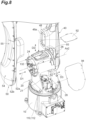
- FIG. 8 illustrates the robot 1 in a state where some members are moved such that the inside of the turning link 20 can be seen.
- FIG. 9 is a sectional view illustrating the inside of the turning link 20.
- FIG. 10 illustrates the robot 1 in a state where some members are moved such that the inside of the arm base portion 62 of the arm link 60 can be seen.
- the opening 24 is provided in the turning link 20.
- the opening 24 (access opening) may be an opening that allows the motor 122 of the actuator 120 to be taken in and out of the turning link 20 from a direction D1 (first direction) along the rotation axis Ax2.
- the opening 24 may have a size that allows the motor 122 to be taken in and out.
- the housing 21 forming the internal space S2 of the turning link 20 may include a pair of side walls crossing the rotation axis Ax2 and a peripheral wall connecting parts of outer edges of the pair of side walls around the rotation axis Ax2.
- the opening 24 may be provided in the side wall of the pair of side walls, which is closer to the auxiliary link 50.
- the motor 122 may be taken in and out of the internal space S2 of the turning link 20 from the direction D 1.
- the direction D1 is, for example, a direction in which the turning link 20 and the drive link 40 are aligned on the rotation axis Ax2.
- the direction D1 may be orthogonal to a plane including the opening 24 (a plane including an opening edge forming the opening 24).
- the motor 122 may be inserted into the internal space S2 or may be taken out from the internal space S2 in a state where the output shaft 122b is horizontal and is along the direction D1.
- the motor 122 is taken in and out by, for example, a worker.
- the robot 1 may include an access cover 54.
- the access cover 54 is a cover that covers the opening 24 provided in the turning link 20.
- the access cover 54 may be configured to be attached to the turning link 20 to cover the motor 122 from the direction D1, and be detached from the turning link 20 such that the motor 122 can be taken in and out of the turning link 20 from the direction D1.
- the access cover 54 may be a part of the auxiliary link 50.
- the proximal end portion of the auxiliary link 50 may function as the access cover 54.
- an opening 26 may be provided in the turning link 20 (housing 21).
- the opening 26 may be provided in the peripheral wall of the housing 21.
- the opening 26 (check opening) is an opening that allows the actuator 120 to be visually recognized from a direction D2 (second direction) crossing the rotation axis Ax2.
- the opening 26 allows the worker to visually recognize the motor 122 when the motor 122 is taken in and out.
- the worker may be able to visually recognize the motor 122 via the opening 26 from the direction D2.
- the direction D2 is a direction crossing a plane including the opening 26 (a plane including an opening edge forming the opening 26).
- the opening 26 is formed to be positioned above the motor 122 attached in the internal space S2. At least a part of the component in the direction D2 may be a component directed vertically downward.
- the opening 26 may have a size that prevents the motor 122 from being taken in and out via the opening.
- the robot 1 may include a check cover 92.
- the check cover 92 is a cover that covers the opening 26 provided in the turning link 20.
- the check cover 92 may be configured to be attached to the turning link 20 to cover the motor 122 from the direction D2, and to be detached from the turning link 20 to allow the motor 122 to be visually recognized from the direction D2.
- the check cover 92 may be attached to the turning link 20 to cover the motor 122 from above.
- the robot 1 may include a check seal 93 (first check seal).
- the check seal 93 is a sealing member interposed between the check cover 92 and the turning link 20.
- the check seal 93 may be configured to seal between the check cover 92 and the turning link 20.
- the check seal 93 is provided, for example, along the opening edge forming the opening 26.
- an opening 28 may be formed in the housing 21.
- the opening 28 (sub-access opening) may be provided in the peripheral wall of the housing 21.
- the opening 28 is an opening that enables access to the motor 122 from a direction D3 (third direction) crossing both the direction D1 and the direction D2. Being able to access the motor 122 means that the worker himself/herself can touch the motor 122 or a tool operated by the worker can touch the motor 122.
- the direction D3 is a direction crossing a plane including the opening 28 (a plane including an opening edge forming the opening 28).
- the actuator 110 may be accommodated in the internal space S2 in the housing 21.
- the motor included in the actuator 110 is referred to as "motor 112”
- the speed reducer included in the actuator 110 is referred to as "speed reducer 114".
- the motor 112 (base motor) is accommodated in the turning link 20 and rotates the turning link 20 around the rotation axis Ax1 (base axis).
- the opening 28 may have a size that allows the motor 112 to be taken in and out of the turning link 20. For example, the worker can insert the motor 112 into the internal space S2 in the turning link 20 and can take out the motor 112 from the internal space S2 via the opening 28.
- the robot 1 may include a sub-access cover 94.
- the sub-access cover 94 is a cover that covers the opening 28 provided in the turning link 20.
- the sub-access cover 94 may be configured to be attached to the turning link 20 to cover the motor 122 from the direction D3, and be detached from the turning link 20 to allow access to the motor 122 from the direction D3.
- the worker attaches the motor 122 for example, the worker detaches the sub-access cover 94, puts his or her hand into the internal space S2 via the opening 28, and performs an attachment work of the motor 122 such that the output shaft 122b of the motor 122 is connected to the speed reducer 124 while supporting the motor 122 from below.
- a lower end of the motor 122 may be positioned above an upper end of the motor 112.
- An upper edge of the opening 28 may be positioned above the upper end of the motor 112, and a lower edge of the opening 28 may be positioned below an upper end of the motor 122.
- the upper edge of the opening 28 may be positioned above the lower end of the motor 122.
- a positional relationship among the motor 112, the motor 122, and the opening 28 means a relationship in a state where the motor 112 and the motor 122 are attached.
- a position of the upper edge of the opening 28 in the axial direction of the rotation axis Ax1 is indicated by "H2”
- a position of the lower edge of the opening 28 in the axial direction of the rotation axis Ax1 is indicated by "H1”.
- the opening 66 may be provided in the arm base portion 62.
- the opening 66 (second access opening) may be an opening that allows the motor 132 of the actuator 130 to be taken in and out of the arm base portion 62 from a direction D11 (third direction) along the rotation axis Ax3.
- the opening 66 may have a size that allows the motor 132 to be taken in and out.
- the housing 65 in the arm base portion 62 may include at least a pair of side walls crossing the rotation axis Ax3.
- the opening 66 may be provided on the side wall of the pair of side walls of the housing 65, which is closer to the auxiliary link 50.
- the motor 132 may be taken in and out of the internal space S6 of the arm base portion 62 from the direction D 11.
- the direction D 11 is, for example, a direction in which the arm base portion 62 and the drive link 40 are aligned on the rotation axis Ax3.
- the direction D 11 may be orthogonal to a plane including the opening 66 (a plane including an opening edge forming the opening 66).
- the motor 132 may be inserted into the internal space S6 or may be taken out from the internal space S6 in a state where the output shaft 132b is horizontal and along the direction D11.
- the motor 132 is taken in and out by, for example, a worker.
- the robot 1 may include an access cover 56 (second access cover).
- the access cover 56 is a cover that covers the opening 66.
- the access cover 56 may be configured to be attached to the arm base portion 62 to cover the motor 132 from the direction D11, and be detached from the arm base portion 62 to allow the motor 132 to be taken in and out from the arm base portion 62 from the direction D11.
- the access cover 56 may be a part of the auxiliary link 50.
- the distal end portion of the auxiliary link 50 may function as the access cover 56.
- the robot 1 includes a connection member 55 constituting the auxiliary link 50 (sub-link).
- the connection member 55 is a portion that couples the access cover 54 and the access cover 56 of the auxiliary link 50 and extends from the access cover 54 to the access cover 56.
- the connection member 55 is formed to extend along a line segment connecting the rotation axis Ax2 and the rotation axis Ax3 at the shortest distance, one end of the connection member 55 is connected to the access cover 54, and the other end of the connection member 55 is connected to the access cover 56.
- the connection member 55 is attached to the drive link 40.
- the auxiliary link 50 may include the link body 52 and the protruding section 58.
- the link body 52 may be formed by the access cover 54, the access cover 56, and a part of connection member 55, and the protruding section 58 may be formed by another part of the connection member 55.
- the connection member 55 may be attached to the drive link 40 by fixing the protruding section 58 of the connection member 55 to the reinforcing section 48 (protruding section 48a) of the drive link 40 as described above.
- the access cover 54 may be formed by a portion of the link body 52 covering the motor 122 and a portion connected to the seal 170.
- the seal 170 (first access seal) described above may be interposed between the turning link 20 and the access cover 54 while allowing the rotation of the auxiliary link 50 relative to the turning link 20.
- the access cover 56 may be formed by a portion of the link body 52 covering the motor 132 and a portion connected to the seal 180.
- the above-described seal 180 (second access seal) may be interposed between the arm base portion 62 and the access cover 56 while allowing the rotation of the auxiliary link 50 with respect to the arm base portion 62.
- the worker When the worker attaches the motor, for example, after the worker detaches the access cover 56, the worker inserts the motor 132 into the internal space S6 such that the output shaft 132b is connected to the speed reducer 134 accommodated in the connecting section 46 of the drive link 40.
- an opening 67 may be provided in the arm base portion 62 (housing 65).
- the opening 67 (second check opening) allows the motor 132 to be visually recognized from a direction D4 (fourth direction) crossing the rotation axis Ax3.
- the opening 67 allows the worker to visually recognize the motor 132 when the motor 132 is taken in and out.
- the worker may be able to visually recognize the motor 132 via the opening 67 from the direction D4.
- the direction D4 is a direction crossing a plane including the opening 67 (a plane including an opening edge forming the opening 67).
- the robot 1 may include a check cover 96 (second check cover).
- the check cover 96 is a cover that covers the opening 67 provided in the arm base portion 62.
- the check cover 96 may be configured to be attached to the arm base portion 62 to cover the motor 132 from the direction D4, and be detached from the arm base portion 62 to make the motor 132 visible from the direction D4.
- the worker attaches the motor 132, for example, the worker detaches the check cover 96, and performs a work while visually recognizing a state such as the inclination of the output shaft 132b from the opening 67.
- the robot 1 may include a check seal 97 (second check seal).
- the check seal 97 is a sealing member interposed between the check cover 96 and the arm base portion 62.
- the check seal 97 may be configured to seal between the check cover 96 and the arm base portion 62.
- the check seal 97 is provided, for example, along an opening edge forming the opening 67.
- the actuator 140 includes a motor 142 (third motor).
- the motor 142 rotates the turning arm 64 around a rotation axis Ax4 (third rotation axis) with respect to the arm base portion 62, the rotation axis Ax4 is along the direction in which the arm base portion 62 extends.
- the motor 142 may be accommodated in the arm base portion 62.
- the motor 142 may be installed such that an output shaft is horizontal.
- the motor 142 may be taken in and out of the internal space S6 of the arm base portion 62 from the direction D4(for example, a direction along the rotation axis Ax4).
- the motor 142 may be inserted into the internal space S6 or may be taken out from the internal space S6 in a state where the output shaft is horizontal and is along the rotation axis Ax4.
- the motor 142 is taken in and out by, for example, a worker.
- the opening 67 may have a size that allows the motor 142 to be taken in and out of the arm base portion 62. The worker can visually recognize the motor 132 and the motor 142 may be taken in and out of the arm base portion 62 via the opening 67.
- an opening 68 may be provided in the arm base portion 62 (housing 65).
- the opening 68 (third check opening) allows the motor 142 to be visually recognized from a direction D5 crossing the rotation axis Ax4.
- the opening 68 allows the worker to visually recognize the motor 142 when the motor 142 is taken in and out.
- the worker may be able to visually recognize the motor 142 via the opening 68 from the direction D5.
- the direction D5 is a direction crossing a plane including the opening 68 (a plane including an opening edge forming the opening 68).
- the robot 1 may include a check cover 98 (third check cover).
- the check cover 98 is a cover that covers the opening 68 provided in the arm base portion 62.
- the check cover 98 may be configured to be attached to the arm base portion 62 to cover the motor 142 from the direction D5, and be detached from the arm base portion 62 to allow the motor 142 to be visually recognized from the direction D5.
- the worker attaches the motor 142, for example, the worker detaches the check cover 98, and performs a work while visually recognizing a state such as the inclination of the motor 142 from the opening 68.
- the entire auxiliary link 50 is detached from the other member and the motor 122 and the motor 132 are taken in and out has been described.
- the motor 122 and the motor 132 may be taken in and out by detaching a cover portion included in the auxiliary link 50 from the other portion of the auxiliary link 50.
- the link body 52 of the auxiliary link 50 may include a body portion 52a and a cover portion 52b (see also FIGS. 7 and 8 ).
- the cover portion 52b may be attached to the body portion 52a via a fixing member 52c.
- a part of the seal 170 and a part of the seal 180 described above may be provided in the body portion 52a.
- a worker may perform an attachment work via a fixing member between the protruding section 58 of the auxiliary link 50 and the reinforcing section 48 of the drive link 40.
- a worker may perform a work of wiring the cable harness 90.
- the motor 122 By detaching the cover portion 52b from the body portion 52a in a state of being fixed to the drive link 40, the motor 122 can be taken in and out via the opened wiring space S5 and opening 24, and the motor 132 can be taken in and out via the opened wiring space S5 and opening 66.
- a portion that covers the opening 24 from the direction D1 along the rotation axis Ax2 may function as the access cover 54 described above.
- a portion covering the opening 66 from the direction D11 along the rotation axis Ax3 may function as the access cover 56 described above.
- the drive link 40 and the auxiliary link 50 may be made of the same material.
- the drive link 40 may be made of a material including aluminum
- the auxiliary link 50 may be made of a material including aluminum. Since the actuator 120 and the actuator 130 are connected to the drive link 40, the influence of heat received from the actuator is different between the drive link 40 and the auxiliary link 50. As a result, even in a case where the drive link 40 and the auxiliary link 50 are made of the same material, the deformation of the drive link 40 and the deformation of the auxiliary link 50 due to the thermal expansion or the like may be different.
- the seal 170 and the seal 180 that do not constrain the movement of the auxiliary link 50 in the direction crossing the rotation axis may be provided in order to allow the positional deviation (for example, the deviation of the rotation axis) due to the difference in the deformation between the links.
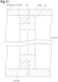
- the robot 1 may include a bearing 178 and a bearing 188 instead of the seal 170 and the seal 180.
- the bearing 178 is a bearing member that holds the auxiliary link 50 to rotate around the rotation axis Ax2.
- the bearing 178 is provided, and thus, the relative movement of the auxiliary link 50 with respect to the turning link 20 may be constrained in the direction crossing the rotation axis Ax2.
- the bearing 188 (second bearing) is a bearing member that holds the auxiliary link 50 to rotate around the rotation axis Ax3 with respect to the arm base portion 62.
- the bearing 188 is provided, and thus, the relative movement of the auxiliary link 50 with respect to the arm base portion 62 may be constrained in the direction crossing the rotation axis Ax3.
- Each of the bearing 178 and the bearing 188 may be any type of bearing member, and is, for example, a ball bearing or a roller bearing.
- the robot 1 may include the bearing 178 in addition to the seal 170.
- the robot 1 may include the bearing 188 in addition to the seal 180.
- the material forming the drive link 40 and the material forming the auxiliary link 50 are different from each other, and the bearing 178 and the bearing 188 are not provided.
- the bearing 178 and the bearing 188 may be provided.
- the bearing 178 and the bearing 188 may not be provided, and the bearing 178 and the bearing 188 may be provided.
- the present disclosure includes the following configurations [1] to [13].
- first sub-link (40) and the second sub-link (50) are made of materials different from each other, deformation of the first sub-link (40) and deformation of the second sub-link (50) due to thermal expansion or the like may be different.
- the positioning accuracy of the distal end of the second link (30) is further improved by suppressing the influence of the second sub-link (50).
Landscapes
- Engineering & Computer Science (AREA)
- Robotics (AREA)
- Mechanical Engineering (AREA)
- Manipulator (AREA)
Abstract
Description
- The present disclosure relates to a robot.
-
Japanese Unexamined Patent Publication No. 2012-161868 - The present disclosure provides a robot effective in reducing unevenness in an appearance and improving positioning accuracy.
- A robot according to an aspect of the present disclosure includes a first link, a second link aligned with the first link along a rotation axis and extending away from the rotation axis, and an actuator accommodated in the first link to rotate the second link around the rotation axis with respect to the first link. The second link includes a first sub-link and a second sub-link that sandwich the actuator along the rotation axis, the first sub-link is attached to the actuator, and the second sub-link is attached to the first sub-link in a state where the second sub-link is not constrained from the first link in a direction crossing the rotation axis.
- According to the present disclosure, the robot effective in reducing the unevenness in the appearance and improving the positioning accuracy is provided.
-
-
FIG. 1 is a perspective view illustrating an example of a robot; -
FIG. 2 is a perspective view illustrating an example of a robot; -
FIG. 3 is a sectional view illustrating an example of an inside of a robot; -
FIG. 4 is a perspective view illustrating an example of a drive link; -
FIG. 5 is a side view illustrating an example of a drive link; -
FIG. 6 is a side view schematically illustrating an example of a drive link; -
FIG. 7 is a sectional view schematically illustrating an example of a seal provided between links; -
FIG. 8 is a perspective view illustrating a part of a robot in a state where a cover is detached; -
FIG. 9 is a sectional view illustrating an example of an inside of a turning link; -
FIG. 10 is a perspective view illustrating a part of a robot in a state where a cover is detached; and -
FIG. 11 is a sectional view schematically illustrating an example of a bearing provided between links. - Hereinafter, embodiments will be described with reference to the drawings. In the description, identical elements or elements having identical functions are denoted by identical reference signs, and redundant description will be omitted.
-
FIGS. 1 and2 illustrate a robot according to an embodiment. Arobot 1 illustrated inFIG. 1 is a vertical articulated robot. Therobot 1 automatically performs various works on a work object. Therobot 1 is, for example, an industrial robot, and in one example, automatically executes various conveyance, machining, assembly, or the like on components or assemblies in production lines of products. The application of therobot 1 is not limited to industrial use. Hereinafter, an outline of a structure of therobot 1 will be first described, and then details of some members included in therobot 1 will be described. - The
robot 1 includes abase portion 2 and an articulatedarm 4. Thebase portion 2 is a portion that supports the articulatedarm 4. The articulatedarm 4 is attached to thebase portion 2 in a state of being rotatable and includes serial link structures. - The
base portion 2 includes abase link 10 and aturning link 20. Thebase link 10 is also referred to as a base, and is fixed to an installation surface. The installation surface may be one surface forming a work area where a work by therobot 1 is performed. The installation surface is, for example, a bottom surface of the work area. Thebase link 10 may be fixed to a horizontal installation surface. Thebase link 10 may be fixed to an installation surface on a moving body such as an automatic guided vehicle (AGV). - The
turning link 20 is connected to thebase link 10 to rotate (turn) around a rotation axis Ax1 (turning axis). Theturning link 20 is attached to thebase link 10 to be positioned above thebase link 10, for example. The rotation axis Ax1 may be set to pass through thebase link 10 and theturning link 20. Theturning link 20 may be provided on thebase link 10 to rotate around the vertical rotation axis Ax1. - In the present disclosure, "upper" and "lower" are used to indicate an arrangement relationship when the structure of the
robot 1 is described. "Upper" and "lower" mean "upper" and "lower" in a state where the rotation axis Ax1 is positioned vertically and theturning link 20 is positioned on thebase link 10, but thebase portion 2 may not necessarily be arranged in this manner. Thebase portion 2 may be arranged, for example, such that theturning link 20 is positioned below thebase link 10 or such that theturning link 20 is positioned on a side of thebase link 10. Thebase link 10 may be fixed to a wall surface of the work area or may be fixed to a ceiling surface of the work area. - The articulated
arm 4 includes, for example, anarm link 30, anarm link 60, anarm link 70, and atool attachment portion 80. Each of thearm link 30, thearm link 60, and thearm link 70 is also simply referred to as an arm. - The
arm link 30 is connected to theturning link 20 to rotate around a rotation axis Ax2. The rotation axis Ax2 crosses, for example, the rotation axis Ax1. In the present disclosure, "crossing" also includes a skew relationship like a so-called grade separation. Thearm link 30 may extend away from the rotation axis Ax2. The arm link 30 (second link) may be aligned with the turning link 20 (first link) along the rotation axis Ax2. The rotation axis Ax2 may be orthogonal to the rotation axis Ax1. The rotation axis Ax2 may be set to pass through a proximal end portion of thearm link 30 and theturning link 20. - The
arm link 60 is connected to thearm link 30 to rotate around a rotation axis Ax3 (second rotation axis) parallel to the rotation axis Ax2. Thearm link 60 is connected to, for example, a distal end portion (end portion) of thearm link 30. Thearm link 60 may extend away from the rotation axis Ax3. The arm link 60 (third link) may be aligned with thearm link 30 along the rotation axis Ax3. The rotation axis Ax3 may be set to pass through the distal end portion of thearm link 30 and a proximal end portion of thearm link 60. - The
arm link 60 includes anarm base portion 62 and a turningarm 64. The arm base portion 62 (third link) is a link connected to the distal end portion of thearm link 30 so as to rotate around the rotation axis Ax3. Thearm base portion 62 may extend away from the rotation axis Ax3. Thearm base portion 62 may be aligned with thearm link 30 along the rotation axis Ax3. The turning arm 64 (fourth link) is a link connected to thearm base portion 62 to rotate around a rotation axis Ax4 crossing the rotation axis Ax3. The turningarm 64 may extend from thearm base portion 62 along a direction in which thearm base portion 62 extends. The rotation axis Ax4 may be orthogonal to the rotation axis Ax3. The rotation axis Ax4 may be set to pass through thearm base portion 62 and the turningarm 64. - The
arm link 70 is connected to thearm link 60 to rotate around a rotation axis Ax5 crossing the rotation axis Ax4. Thearm link 70 is attached to, for example, a distal end portion of the turningarm 64 of thearm link 60. The rotation axis Ax5 may be orthogonal to the rotation axis Ax4. The rotation axis Ax5 may be set to pass through the distal end portion of the turningarm 64 and thearm link 70. - The
tool attachment portion 80 is connected to thearm link 70 to rotate around a rotation axis Ax6 crossing the rotation axis Ax5. The rotation axis Ax6 may be orthogonal to the rotation axis Ax5. The rotation axis Ax6 may be set to pass through thearm link 70 and thetool attachment portion 80. A working tool is attached to thetool attachment portion 80. An example of the working tool is a suction nozzle configured to suck a workpiece, a hand configured to grip a workpiece, a welding torch, a screw tightening tool, or a polishing tool. - The
robot 1 includes anactuator 110, anactuator 120, anactuator 130, anactuator 140, anactuator 150, and anactuator 160. InFIG. 1 , each actuator is schematically illustrated by a broken line in a simplified manner, and a diagram of each actuator is omitted inFIG. 2 . Each actuator may include a motor and a speed reducer. - The
actuator 110 rotates the turninglink 20 around the rotation axis Ax1 with respect to thebase link 10. Theactuator 120 rotates thearm link 30 around the rotation axis Ax2 with respect to the turninglink 20. The actuator 130 (second actuator) rotates thearm base portion 62 of thearm link 60 around the rotation axis Ax3 with respect to thearm link 30. - The
actuator 140 rotates the turningarm 64 of thearm link 60 around the rotation axis Ax4 with respect to thearm base portion 62. Theactuator 150 rotates thearm link 70 around the rotation axis Ax5 with respect to the turningarm 64 of thearm link 60. Theactuator 160 rotates thetool attachment portion 80 around the rotation axis Ax6 with respect to thearm link 70. - Next, a structure of the
arm link 30 and some members positioned inside or around thearm link 30 will be described in detail. Thearm link 30 may include two sub-links. As illustrated inFIG. 1 or2 , thearm link 30 may include a drive link 40 (link) and anauxiliary link 50 as two sub-links. - The drive link 40 (first sub-link) and the auxiliary link 50 (second sub-link) may sandwich the
actuator 120 along the rotation axis Ax2. In a case where the members are observed on the rotation axis Ax2, thedrive link 40, theactuator 120, and theauxiliary link 50 may be arranged in this order. Thedrive link 40 and theauxiliary link 50 may sandwich theactuator 130 along the rotation axis Ax3. When the members are observed on the rotation axis Ax3, thedrive link 40, theactuator 130, and theauxiliary link 50 may be arranged in this order. - The
auxiliary link 50 may be made of a material (second material) having rigidity and specific gravity smaller than a material (first material) forming thedrive link 40. The rigidity of the material forming theauxiliary link 50 may be smaller than the rigidity of the material forming thedrive link 40, and the specific gravity of the material forming theauxiliary link 50 may be smaller than the specific gravity of the material forming thedrive link 40. For example, in a case where the material forming thedrive link 40 is a material containing iron, the material forming theauxiliary link 50 is a material containing aluminum. A thermal expansion coefficient (linear expansion coefficient) may be different between the material forming thedrive link 40 and the material forming theauxiliary link 50. - The
drive link 40 is a link driven by theactuator 120. For example, a driving force by theactuator 120 is directly transmitted to thedrive link 40. Thedrive link 40 may be connected to the turninglink 20. Theactuator 120 rotates thedrive link 40 around the rotation axis Ax2 with respect to the turninglink 20.FIG. 3 illustrates a section taken along line III-III drawn inFIG. 2 . Theactuator 120 is connected to any portion of thedrive link 40. The drive link 40 (second link) may be aligned with the turning link 20 (first link) along the rotation axis Ax2. Thedrive link 40 may extend away from the rotation axis Ax2. - The
actuator 120 may be accommodated in the turninglink 20. The turninglink 20 may include an internal space S2 and an opening 24 (see alsoFIG. 8 ). The internal space S2 is a space for accommodating theactuator 120. At least a part of theactuator 120 may be accommodated in the internal space S2. The turninglink 20 includes ahousing 21. Thehousing 21 is constituted by a wall forming the internal space S2. Theopening 24 is an opening formed in thehousing 21. - In
FIG. 3 , the motor included in theactuator 120 is indicated by "122", and the speed reducer included in theactuator 120 is indicated by "124". Themotor 122 includes amotor body 122a and anoutput shaft 122b. Themotor 122 rotates thedrive link 40 around the rotation axis Ax2 with respect to the turninglink 20. Themotor 122 may be accommodated in the internal space S2 in the turninglink 20. Themotor 122 may be arranged such that themotor body 122a is accommodated in the internal space S2 in the turninglink 20. Themotor 122 may be installed such that theoutput shaft 122b is horizontal. Theoutput shaft 122b of themotor 122 is connected to thespeed reducer 124. In one example, an output shaft of thespeed reducer 124 of theactuator 120 is connected to thedrive link 40. - The
actuator 130 for driving thearm base portion 62 of thearm link 60 rotates thearm base portion 62 around the rotation axis Ax3 with respect to thedrive link 40 of thearm link 30. Theactuator 130 is connected to any portion of thedrive link 40. For example, a driving force by theactuator 130 is applied to thedrive link 40, and thus, thearm base portion 62 rotates with respect to thedrive link 40. The arm base portion 62 (second link) of thearm link 60 may be connected to an end portion of thedrive link 40. The arm base portion 62 (second link) of thearm link 60 may be aligned with thedrive link 40. - The
actuator 130 may be accommodated in thearm base portion 62 of thearm link 60. Thearm base portion 62 of thearm link 60 may include an internal space S6 and an opening 66 (see alsoFIG. 10 ). The internal space S6 is a space for accommodating theactuator 130. At least a part of theactuator 130 may be accommodated in the internal space S6. Thearm base portion 62 of thearm link 60 has ahousing 65. Thehousing 65 is constituted by a wall forming the internal space S6. Theopening 66 is an opening formed in thehousing 65. - In
FIG. 3 , the motor included in theactuator 130 is indicated by "132", and the speed reducer included in theactuator 130 is indicated by "134". Themotor 132 includes amotor body 132a and anoutput shaft 132b. The motor 132 (second motor) rotates thearm base portion 62 around the rotation axis Ax3 with respect to thedrive link 40. Themotor 132 may be accommodated in thearm base portion 62. Themotor 132 may be arranged such that themotor body 132a is accommodated in the internal space S6 in thearm base portion 62. Themotor 132 may be installed such that theoutput shaft 132b is horizontal. Theoutput shaft 132b of themotor 132 is connected to thespeed reducer 134. In one example, an output shaft of thespeed reducer 134 of theactuator 130 is connected to thedrive link 40. -
FIG. 4 illustrates a perspective view of thedrive link 40, andFIG. 5 illustrates a side view of thedrive link 40 as viewed from a direction along the rotation axis Ax2.FIG. 6 is a schematic view in a case where a side surface of thedrive link 40 is viewed from a direction orthogonal to a plane including the rotation axis Ax2 and the rotation axis Ax3. As illustrated inFIG. 4 and the like, thedrive link 40 is formed to extend over both the rotation axis Ax2 and the rotation axis Ax3. A direction in which theentire drive link 40 extends may be along a line segment connecting the rotation axis Ax2 and the rotation axis Ax3 at a shortest distance. - The
drive link 40 may be attached to theactuator 120. Thedrive link 40 may be attached to theactuator 130. Thedrive link 40 includes, for example, a connectingsection 42, a connectingsection 46, alink base section 44, and a reinforcingsection 48. In a case where thedrive link 40 is observed from the rotation axis Ax2 toward the rotation axis Ax3, the connectingsection 42, thelink base section 44, and the connectingsection 46 are aligned in this order. - The connecting
section 42 is a portion connected to theactuator 120. For example, the output shaft of thespeed reducer 124 of theactuator 120 is connected to the connectingsection 42. The connectingsection 42 may include a connectingbase section 42a and asurrounding wall 42b. A space for accommodating at least a part of the actuator 120 (for example, thespeed reducer 124 of the actuator 120) is formed by the connectingbase section 42a and the surroundingwall 42b. - The connecting
base section 42a is a portion connected to theactuator 120. For example, the output shaft of thespeed reducer 124 of theactuator 120 is connected to the connectingbase section 42a. The connectingbase section 42a may be formed to spread along a plane crossing the rotation axis Ax2. A thickness of the connectingbase section 42a may not be constant, and at least a part of each of a pair of main surfaces of the connectingbase section 42a may not be a plane. A shape of the connectingbase section 42a may be circular as viewed from the rotation axis Ax2. - The surrounding
wall 42b is a portion protruding from the connectingbase section 42a to surround at least a part of theactuator 120. The surroundingwall 42b is formed in an annular shape to surround at least a part of thespeed reducer 124, for example. The surroundingwall 42b protrudes in a predetermined direction from an outer edge portion (outer edge and a portion in the vicinity thereof) of the connectingbase section 42a. The surroundingwall 42b protrudes, for example, in an axial direction in which the rotation axis Ax2 extends. - The connecting section 46 (second connecting section) is a portion connected to the actuator 130 (second actuator). For example, the output shaft of the
speed reducer 134 of theactuator 130 is connected to the connectingsection 46. The connectingsection 46 may include a connectingbase section 46a (second connecting base section) and asurrounding wall 46b (second surrounding wall). A space for accommodating at least a part of the actuator 130 (for example, thespeed reducer 134 of the actuator 130) is formed by the connectingbase section 46a and the surroundingwall 46b. - The connecting
base section 46a is a portion connected to theactuator 130. For example, the output shaft of thespeed reducer 134 of theactuator 130 is connected to the connectingbase section 46a. The connectingbase section 46a may be formed to spread along the plane crossing the rotation axis Ax2. A thickness of at least a part of the connectingbase section 46a may not be constant, and at least a part of each of a pair of main surfaces of the connectingbase section 46a may not be a plane. A shape of the connectingbase section 46a may be circular as viewed from the rotation axis Ax3. - The surrounding
wall 46b is a portion protruding from the connectingbase section 46a to surround at least a part of theactuator 130. The surroundingwall 46b is formed in an annular shape to surround at least a part of thespeed reducer 134, for example. The surroundingwall 46b protrudes in a predetermined direction from an outer edge portion (outer edge and a portion in the vicinity thereof) of the connectingbase section 46a. The surroundingwall 46b protrudes, for example, in an axial direction in which the rotation axis Ax3 extends. - The
link base section 44 is a portion extending from the connectingsection 42 while crossing the rotation axis Ax2. Thelink base section 44 is connected to the connectingsection 46 and also crosses the rotation axis Ax3. Thelink base section 44 may be formed to spread along the plane crossing the rotation axis Ax2. A thickness of at least a part of thelink base section 44 may not be constant, and at least a part of each of a pair of main surfaces of thelink base section 44 may not be a plane. - As viewed from the axial directions of the rotation axis Ax2 and the rotation axis Ax3, the
link base section 44 is formed to extend along a virtual line segment connecting the rotation axis Ax2 and the rotation axis Ax3. The connectingbase section 42a of the connectingsection 42 is continued to thelink base section 44, and the connectingbase section 46a of the connectingsection 46 is continued to thelink base section 44. The connecting section 42 (the connectingbase section 42a and the surroundingwall 42b), thelink base section 44, and the connecting section 46 (the connectingbase section 46a and the surroundingwall 46b) may be integrally formed. - Here, as viewed from a direction parallel to the rotation axis Ax2 and the rotation axis Ax3, a direction orthogonal to a virtual straight line passing through the rotation axis Ax2 and the rotation axis Ax3 is defined as a "width direction" in the
drive link 40. Thelink base section 44 is formed such that a size in the width direction decreases at a central portion between the rotation axis Ax2 and the rotation axis Ax3. The size of thelink base section 44 in the width direction increases as it approaches the connectingsection 42, starting from the central portion between the rotation axis Ax2 and the rotation axis Ax3. The size of thelink base section 44 in the width direction increases as it approaches the connectingsection 46, starting from the central portion between the rotation axis Ax2 and the rotation axis Ax3. - The reinforcing
section 48 is formed to increase rigidity while reducing a weight of thedrive link 40. The reinforcingsection 48 may be formed to protrude from thelink base section 44 between the connectingsection 42 and an end portion (an end portion close to the rotation axis Ax3) of thelink base section 44. For example, the reinforcingsection 48 is formed integrally with thelink base section 44 to protrude from thelink base section 44 between the connectingsection 42 and the connectingsection 46. The reinforcingsection 48 may protrude in the same direction as the surroundingwall 42b and the surroundingwall 46b, and may be connected to the surroundingwall 42b and the surroundingwall 46b. - The reinforcing
section 48 includes a protrudingsection 48a. The protrudingsection 48a is a portion protruding from thelink base section 44 at a position away from each of the connectingsection 42 and the end portion of the link base section 44 (the end portion close to the rotation axis Ax3). The protrudingsection 48a may be formed in an annular shape around an axis Ax0 crossing thelink base section 44. The axis Ax0 is a virtual axis that crosses a direction in which thelink base section 44 extends and passes through thelink base section 44. As viewed from the direction parallel to the rotation axis Ax2 and the rotation axis Ax3, the protrudingsection 48a surrounds the axis Ax0. The axis Ax0 may pass through a center of gravity of a region defined by an opening edge at an inner edge of the annular protrudingsection 48a. A length of a line segment connecting the rotation axis Ax2 and the axis Ax0 at a shortest distance may be about 0.8 to 1.2 times a length of a line segment connecting the rotation axis Ax3 and the axis Ax0 at a shortest distance. - At least a part of the protruding
section 48a may be formed such that the size in the width direction decreases as it extends away from thelink base section 44. Instead of or in addition to the width direction, at least a part of the protrudingsection 48a may be formed such that the size in the direction in which thelink base section 44 extends decreases as a distance from thelink base section 44 increases. As viewed from the direction parallel to the rotation axis Ax2 and the rotation axis Ax3, an end surface of the protrudingsection 48a in the direction parallel to the rotation axis Ax2 and the rotation axis Ax3 (an end surface along the direction crossing the axis Ax0) may be positioned inside an outer edge of thelink base section 44. In the width direction, a maximum width of the end surface of the protrudingsection 48a is smaller than a minimum width of thelink base section 44. A protruding height of the protrudingsection 48a from thelink base section 44 may be higher than a protruding height of the surroundingwall 42b from the connectingbase section 42a, or may be higher than the protruding height of the surroundingwall 46b from the connectingbase section 46a. - The reinforcing
section 48 may include one ormore ribs 48b. Therib 48b may be formed to protrude from thelink base section 44, and may be connected to at least the protrudingsection 48a. As illustrated inFIG. 4 and the like, therib 48b may be formed to connect the protrudingsection 48a and the connectingsection 42. One end of therib 48b may be connected to the protrudingsection 48a, and the other end of therib 48b may be connected to the connectingsection 42. Unlike the example illustrated inFIG. 4 and the like, therib 48b may be connected to the protrudingsection 48a without being connected to the connectingsection 42. In one example, the protrudingsection 48a and therib 48b protrude in the same direction as the surroundingwall 42b of the connectingsection 42, and therib 48b (the other end of therib 48b) is connected to the surroundingwall 42b. At least in the direction in which thelink base section 44 extends, a protruding height of therib 48b with respect to thelink base section 44 may be increased as a distance from the protrudingsection 48a decreases. Even in a direction crossing the direction in which thelink base section 44 extends, the protruding height of therib 48b with respect to thelink base section 44 may increase as a distance from the protrudingsection 48a decreases. - The reinforcing
section 48 may include one ormore ribs 48c (second ribs). Therib 48c may be formed to protrude from thelink base section 44, and may be connected to at least the protrudingsection 48a. As illustrated inFIG. 4 and the like, therib 48c may be formed to connect the protrudingsection 48a and the connectingsection 46. One end of therib 48c may be connected to the protrudingsection 48a, and the other end of therib 48b may be connected to the connectingsection 46. Unlike the example illustrated inFIG. 4 and the like, therib 48c may be connected to the protrudingsection 48a without being connected to the connectingsection 46. In one example, the protrudingsection 48a and therib 48c protrude in the same direction as the surroundingwall 46b of the connectingsection 46, and therib 48c (the other end of therib 48b) is connected to the surroundingwall 46b. At least in the direction in which thelink base section 44 extends, a protruding height of therib 48c with respect to thelink base section 44 may be increased as a distance from the protrudingsection 48a decreases. Even in the direction crossing the direction in which thelink base section 44 extends, the protruding height of therib 48c with respect to thelink base section 44 may increase as a distance from the protrudingsection 48a decreases. - The reinforcing
section 48 may include one of one ormore ribs 48b and one ormore ribs 48c, or may include both of one ormore ribs 48b and one ormore ribs 48c. The reinforcingsection 48 may include the protrudingsection 48a without having both of one ormore ribs 48b and one ormore ribs 48c. Hereinafter, a case where both one ormore ribs 48b and one ormore ribs 48c are provided will be exemplified. - A protruding height of the end surface of the protruding
section 48a which faces away thelink base section 44 may be substantially constant. A protruding height of a certain point of the reinforcingsection 48 is defined by a shortest distance between that point and a reference position set in thelink base section 44, along a line passing through that point and extending in the axial direction of the rotation axis Ax2. - The protruding
section 48a may be a solid rib (protrusion) instead of the rib (protrusion) formed in the annular shape. When a section of the protrudingsection 48a orthogonal to the rotation axis Ax2 is observed, the section may be annular, or may be a solid (state where an inside of an object is clogged). In one example, the reinforcingsection 48 includes a plurality ofribs 48b as one ormore ribs 48b, and includes a plurality ofribs 48c as one ormore ribs 48c. - Each of the plurality of
ribs 48b is a rib (protrusion) that connects the protrudingsection 48a and the surroundingwall 42b of the connectingsection 42. Each of the plurality ofribs 48b extends from one of the protrudingsection 48a and the surroundingwall 42b toward the other. In a case where attention is paid to eachrib 48b included in the plurality ofribs 48b, one end of therib 48b is connected to the protrudingsection 48a, and the other end of therib 48b is connected to the surroundingwall 42b. - An interval between the plurality of
ribs 48b may increase as the distance from the protrudingsection 48a increases. The interval between the plurality ofribs 48b is defined by a shortest distance between onerib 48b and anotherrib 48b in the width direction. In a case where three ormore ribs 48b are provided, an interval between at least one any selected pair ofribs 48b may increase as the distance from the protrudingsection 48a increases. In three ormore ribs 48b, for all combinations of the pair ofribs 48b, the interval between the pair ofribs 48b may increase as the distance from the protrudingsection 48a increases. - For at least a part of the plurality of
ribs 48b, the protruding height of therib 48b may decrease as the distance from the protrudingsection 48a increases. In other words, for at least a part of the plurality ofribs 48b, the protruding height of therib 48b may increase as the distance from the protrudingsection 48a decreases. For all of the plurality ofribs 48b, the protruding height of therib 48b may decrease as the distance from the protrudingsection 48a increases. - Each of the plurality of
ribs 48c (the plurality of second ribs) is a rib (protrusion) that connects the protrudingsection 48a and the surroundingwall 46b of the connectingsection 46. Each of the plurality ofribs 48c extends from one of the protrudingsection 48a and the surroundingwall 46b toward the other. In a case where attention is paid to eachrib 48c included in the plurality ofribs 48c, one end of therib 48c is connected to the protrudingsection 48a, and the other end of therib 48c is connected to the surroundingwall 46b. - The interval between the plurality of
ribs 48c may increase as the distance from the protrudingsection 48a increases. An interval between the plurality ofribs 48c is defined by a shortest distance between onerib 48c and anotherrib 48c in the width direction. In a case where three ormore ribs 48c are provided, an interval between at least one any selected pair ofribs 48c may increase as the distance from the protrudingsection 48a increases. In three ormore ribs 48c, for all combinations of the pair ofribs 48c, the interval between the pair ofribs 48c may increase as the distance from the protrudingsection 48a increases. - For at least a part of the plurality of
ribs 48c, the protruding height of therib 48c may decrease as the distance from the protrudingsection 48a increases. In other words, for at least a part of the plurality ofribs 48c, the protruding height of therib 48c may increase as the distance from the protrudingsection 48a decreases. For all of the plurality ofribs 48c, the protruding height of therib 48c may decrease as the distance from the protrudingsection 48a increases. - Referring back to
FIG. 3 , theauxiliary link 50 is a link that rotates as thedrive link 40 is driven. Theauxiliary link 50 may extend over between the rotation axis Ax2 and the rotation axis Ax3, and may rotate around the rotation axis Ax2 together with thedrive link 40. Theactuator 120 that rotates thearm link 30 may not be connected to theauxiliary link 50, and the driving force by theactuator 120 may not be directly transmitted. Theactuator 130 that rotates thearm link 60 may not be connected to theauxiliary link 50. - Similarly to the
drive link 40, theauxiliary link 50 may be formed to extend along a line segment connecting the rotation axis Ax2 and the rotation axis Ax3 at a shortest distance. Each of theactuator 120 and theactuator 130 is positioned between thedrive link 40 and theauxiliary link 50. Theactuator 120 may be arranged between the connectingsection 42 of thedrive link 40 and a proximal end portion (an end portion through which the rotation axis Ax2 passes) of theauxiliary link 50. Theactuator 130 may be arranged between the connectingsection 46 of thedrive link 40 and a distal end portion (an end portion through which the rotation axis Ax3 passes) of theauxiliary link 50. - The
robot 1 may include acable harness 90. Thecable harness 90 is connected to at least theactuator 120, for example. Thecable harness 90 may be connected to at least theactuator 130 via the internal space S2 of the turninglink 20. Thecable harness 90 may include two or more cables. Thecable harness 90 may be connected to at least theactuator 120 and theactuator 130. In thecable harness 90, the cable connected to theactuator 120 may be different from the cable connected to theactuator 130. Thecable harness 90 may be physically and electrically connected to each of theactuator 120 and theactuator 130. Thecable harness 90 may include at least one of a cable that supplies power to theactuator 120, a cable that supplies power to theactuator 130, a cable that transmits a signal to or/and from theactuator 120, and a cable that transmits a signal to or/and from theactuator 130. Thecable harness 90 may be connected to at least themotor 132 via an inside (internal space S2) of the turninglink 20. Thecable harness 90 may be connected to at least themotor 122 and themotor 132. - The
auxiliary link 50 may include a wiring space S5 for guiding thecable harness 90. The wiring space S5 may be a space for guiding thecable harness 90 from the internal space S2 to theactuator 130. Thecable harness 90 may be accommodated in the wiring space S5 formed by theauxiliary link 50. Theauxiliary link 50 may accommodate thecable harness 90 such that thecable harness 90 is not exposed to an outside. - The
opening 24 of the turninglink 20 described above may be an opening that allows the internal space S2 of the turninglink 20 to communicate with an outside of the internal space S2. Theopening 24 may allow the internal space S2 of the turninglink 20 to communicate with the wiring space S5. Thecable harness 90 may be wired through theopening 24 and the wiring space S5. The opening 66 (second opening) of thearm link 60 described above may be an opening that allows the internal space S6 (second internal space) of thearm link 60 to communicate with an outside of the internal space S6. Theopening 66 may allow the internal space S6 of thearm link 60 to communicate with the wiring space S5. Thecable harness 90 may be wired from the internal space S2 to the internal space S6 via theopening 24, the wiring space S5, and theopening 66. The wiring space S5 may be a space for guiding thecable harness 90 from the inside of the turning link 20 (internal space S2) to the inside of the arm base portion 62 (internal space S6). - The
auxiliary link 50 may be attached to the reinforcingsection 48 of thedrive link 40. For example, theauxiliary link 50 is fixed to the end surface of the protrudingsection 48a of the reinforcingsection 48 facing theauxiliary link 50 by a fixing member. An internal space S4, which is a space inside the protrudingsection 48a formed in an annular shape, and the wiring space S5 in theauxiliary link 50 may communicate with each other at a connecting portion between theauxiliary link 50 and the reinforcingsection 48. - The
auxiliary link 50 may include a link body 52 (sub-link body) and a protruding section 58 (sub-protruding section) (see alsoFIG. 2 ). Thelink body 52 is a body portion of theauxiliary link 50, and is a portion extending over between the rotation axis Ax2 and the rotation axis Ax3. The protrudingsection 58 is a portion protruding from thelink body 52 toward the reinforcingsection 48, and may be formed in an annular shape. The protrudingsection 58 may be attached to the reinforcingsection 48 of thedrive link 40. The protrudingsection 58 may include an end surface facing thedrive link 40, and the protrudingsection 58 and the reinforcingsection 48 may be fixed to each other in a state where the end surface of the protrudingsection 58 comes into contact with a corresponding end surface of the protrudingsection 48a of the reinforcingsection 48. - The
auxiliary link 50 may be attached to thedrive link 40 in a state of not being constrained from the turninglink 20 in a direction crossing the rotation axis Ax2. Theauxiliary link 50 may be fixed to thedrive link 40 in a state where relative movement with respect to the turninglink 20 is possible in the direction crossing the rotation axis Ax2. Therobot 1 may include a bearing that holds theauxiliary link 50 to rotate around the rotation axis Ax2. - The
auxiliary link 50 may be attached to thedrive link 40 in a state of not being constrained from the turninglink 20 in the direction crossing the rotation axis Ax2 and not being constrained from the arm base portion 62 (arm link 60) in a direction crossing the rotation axis Ax3. Theauxiliary link 50 may be fixed to thedrive link 40 in a state where the relative movement with respect to the turninglink 20 is possible in the direction crossing the rotation axis Ax2 and relative movement with respect to the arm base portion 62 (arm link 60) is possible in the direction crossing the rotation axis Ax3. Therobot 1 may include a bearing that holds theauxiliary link 50 to rotate around the rotation axis Ax3. -
FIG. 7 is an enlarged view of portions indicated by "A" and "B" inFIG. 3 , andFIG. 7 schematically illustrates a seal installed between the links. Therobot 1 may include a seal 170. The seal 170 is a member (sealing member) interposed between theauxiliary link 50 and the turninglink 20 around theopening 24. The seal 170 may be configured to seal between theauxiliary link 50 and the turning link 20 (to close a gap between theauxiliary link 50 and the turning link 20). For example, the seal 170 is interposed at a connecting portion between theauxiliary link 50 and the turninglink 20, and thus, it is possible to prevent a liquid such as water from entering the internal space S2 of the turninglink 20 from the outside and a liquid such as water from entering the wiring space S5 via the connecting portion. - The seal 170 may be configured to be interposed between the
auxiliary link 50 and the turning link 20 (to seal between theauxiliary link 50 and the turning link 20) while allowing the relative displacement between theauxiliary link 50 and the turninglink 20 in the direction crossing the rotation axis Ax2. The seal 170 includes, for example, a first member 172 and a second member 174. Each of the first member 172 and the second member 174 is formed in an annular shape around the rotation axis Ax2. The first member 172 and the second member 174 are arranged to face each other in the axial direction of the rotation axis Ax2. The first member 172 is connected to an inner wall surface forming theopening 24 in the turninglink 20. The second member 174 is connected to a portion of the proximal end portion of theauxiliary link 50, which is attached to the turninglink 20. - The first member 172 and the second member 174 come into contact with each other while allowing relative displacement therebetween. The first member 172 includes a sealing surface 172a. The sealing surface 172a is a surface along a plane crossing the rotation axis Ax2. The sealing surface 172a may be along a plane orthogonal to the rotation axis Ax2. The sealing surface 172a is formed in an annular shape around the rotation axis Ax2.
- The second member 174 includes a sealing element 174a. The sealing element 174a is an element (portion) that is displaced along the sealing surface 172a in accordance with the relative displacement between the
auxiliary link 50 and the turninglink 20 while being in close contact with the sealing surface 172a of the first member 172. The seal 170 is formed such that a state where the sealing element 174a comes into contact with the sealing surface 172a is maintained even though the relative displacement between theauxiliary link 50 and the turninglink 20 occurs. The sealing element 174a is formed in an annular shape around the rotation axis Ax2. The sealing element 174a may be formed to spread from a body portion of the second member 174 in a radial direction of a circle with the rotation axis Ax2 as a center in a state of being inclined with respect to the rotation axis Ax2. - The seal 170 including the sealing surface 172a and the sealing element 174a may be formed in any manner. The first member 172 including the sealing surface 172a may be provided on the
auxiliary link 50, and the second member 174 including the sealing element 174a may be provided on the turninglink 20. - In addition to the seal 170, the
robot 1 may include a seal 180 (second seal). The seal 180 is a member (sealing member) interposed between theauxiliary link 50 and thearm base portion 62 of thearm link 60 around theopening 66. The seal 180 may be formed to seal between theauxiliary link 50 and the arm base portion 62 (to close a gap between theauxiliary link 50 and the arm base portion 62). For example, the seal 180 is interposed at a connecting portion between theauxiliary link 50 and thearm base portion 62 of thearm link 60, and thus, it is possible to prevent a liquid such as water from entering the internal space S6 of thearm link 60 from the outside and a liquid such as water from entering the wiring space S5 via the connecting portion. - The seal 180 may be formed to be interposed between the
auxiliary link 50 and the arm base portion 62 (to seal between theauxiliary link 50 and the arm base portion 62) while allowing relative displacement between theauxiliary link 50 and thearm base portion 62 in the direction crossing the rotation axis Ax3. The seal 180 includes, for example, a first member 182 and a second member 184. The first member 182 and the second member 184 are arranged to face each other in the axial direction of the rotation axis Ax3. The first member 182 is connected to an inner wall surface forming theopening 66 in thearm base portion 62. The second member 184 is connected to a portion of the distal end portion of theauxiliary link 50, which is attached to thearm base portion 62. - The first member 182 and the second member 184 comes into contact with each other while allowing relative displacement therebetween. The first member 182 includes a sealing surface 182a. The sealing surface 182a is a surface along a plane crossing the rotation axis Ax3. The sealing surface 182a may be along a plane orthogonal to the rotation axis Ax3. The sealing surface 182a is formed in an annular shape around the rotation axis Ax3.
- The second member 174 includes a sealing element 184a. The sealing element 184a is an element (portion) that is displaced along the sealing surface 182a in accordance with the relative displacement between the
auxiliary link 50 and thearm link 60 while being in close contact with the sealing surface 182a of the first member 182. The seal 180 is formed such that a state where the sealing element 184a comes into contact with the sealing surface 182a is maintained even though the relative displacement between theauxiliary link 50 and thearm link 60 occurs. The sealing element 184a is formed in an annular shape around the rotation axis Ax3. The sealing element 184a may be formed to spread from a body portion of the second member 184 in a radial direction of a circle with the rotation axis Ax3 as a center in a state of being inclined with respect to the rotation axis Ax3. - The seal 180 including the sealing surface 182a and the sealing element 184a may be formed in any manner. The first member 182 including the sealing surface 182a may be provided on the
auxiliary link 50, and the second member 184 including the sealing element 184a may be provided on thearm base portion 62. - In a case where the materials forming the
drive link 40 and theauxiliary link 50 are different from each other, the deformation of thedrive link 40 and the deformation of theauxiliary link 50 due to thermal expansion or the like may be different depending on the difference between the thermal expansion coefficients of the materials. By contrast, since the seal 170 and the seal 180 do not constrain the movement of theauxiliary link 50 in the direction crossing the rotation axis, it is possible to allow a positional deviation (for example, a deviation of the rotation axis) due to the difference in the deformation between the links. - Next, a structure for performing maintenance of a motor of an actuator included in the
robot 1 will be described. The maintenance of the motor may include replacement of the motor.FIG. 8 illustrates therobot 1 in a state where some members are moved such that the inside of the turninglink 20 can be seen.FIG. 9 is a sectional view illustrating the inside of the turninglink 20.FIG. 10 illustrates therobot 1 in a state where some members are moved such that the inside of thearm base portion 62 of thearm link 60 can be seen. - As illustrated in
FIG. 8 , theopening 24 is provided in the turninglink 20. The opening 24 (access opening) may be an opening that allows themotor 122 of theactuator 120 to be taken in and out of the turninglink 20 from a direction D1 (first direction) along the rotation axis Ax2. Theopening 24 may have a size that allows themotor 122 to be taken in and out. Thehousing 21 forming the internal space S2 of the turninglink 20 may include a pair of side walls crossing the rotation axis Ax2 and a peripheral wall connecting parts of outer edges of the pair of side walls around the rotation axis Ax2. Theopening 24 may be provided in the side wall of the pair of side walls, which is closer to theauxiliary link 50. - The
motor 122 may be taken in and out of the internal space S2 of the turninglink 20 from thedirection D 1. The direction D1 is, for example, a direction in which theturning link 20 and thedrive link 40 are aligned on the rotation axis Ax2. The direction D1 may be orthogonal to a plane including the opening 24 (a plane including an opening edge forming the opening 24). Themotor 122 may be inserted into the internal space S2 or may be taken out from the internal space S2 in a state where theoutput shaft 122b is horizontal and is along the direction D1. Themotor 122 is taken in and out by, for example, a worker. - The
robot 1 may include anaccess cover 54. The access cover 54 is a cover that covers theopening 24 provided in the turninglink 20. The access cover 54 may be configured to be attached to the turninglink 20 to cover themotor 122 from the direction D1, and be detached from the turninglink 20 such that themotor 122 can be taken in and out of the turninglink 20 from the direction D1. The access cover 54 may be a part of theauxiliary link 50. The proximal end portion of theauxiliary link 50 may function as theaccess cover 54. When the worker attaches themotor 122, for example, the worker detaches theaccess cover 54, then the worker inserts themotor 122 into the internal space S2 such that theoutput shaft 122b is connected to thespeed reducer 124 accommodated in the connectingportion 42 of thedrive link 40. - In addition to the
opening 24, anopening 26 may be provided in the turning link 20 (housing 21). Theopening 26 may be provided in the peripheral wall of thehousing 21. The opening 26 (check opening) is an opening that allows theactuator 120 to be visually recognized from a direction D2 (second direction) crossing the rotation axis Ax2. Theopening 26 allows the worker to visually recognize themotor 122 when themotor 122 is taken in and out. The worker may be able to visually recognize themotor 122 via theopening 26 from the direction D2. The direction D2 is a direction crossing a plane including the opening 26 (a plane including an opening edge forming the opening 26). Theopening 26 is formed to be positioned above themotor 122 attached in the internal space S2. At least a part of the component in the direction D2 may be a component directed vertically downward. Theopening 26 may have a size that prevents themotor 122 from being taken in and out via the opening. - The
robot 1 may include acheck cover 92. Thecheck cover 92 is a cover that covers theopening 26 provided in the turninglink 20. Thecheck cover 92 may be configured to be attached to the turninglink 20 to cover themotor 122 from the direction D2, and to be detached from the turninglink 20 to allow themotor 122 to be visually recognized from the direction D2. Thecheck cover 92 may be attached to the turninglink 20 to cover themotor 122 from above. When the worker attaches themotor 122, for example, the worker detaches thecheck cover 92, and performs a work while visually recognizing a state such as the inclination of theoutput shaft 122b from theopening 26. - The
robot 1 may include a check seal 93 (first check seal). Thecheck seal 93 is a sealing member interposed between thecheck cover 92 and the turninglink 20. Thecheck seal 93 may be configured to seal between thecheck cover 92 and the turninglink 20. Thecheck seal 93 is provided, for example, along the opening edge forming theopening 26. By providing thecheck seal 93, a substance such as a liquid is prevented from entering the internal space S2 from the outside via the connecting portion between thecheck cover 92 and the turninglink 20, and a substance such as a liquid is prevented from leaking from the internal space S2 to the outside. - In addition to the
opening 24 and theopening 26, anopening 28 may be formed in thehousing 21. The opening 28 (sub-access opening) may be provided in the peripheral wall of thehousing 21. Theopening 28 is an opening that enables access to themotor 122 from a direction D3 (third direction) crossing both the direction D1 and the direction D2. Being able to access themotor 122 means that the worker himself/herself can touch themotor 122 or a tool operated by the worker can touch themotor 122. The direction D3 is a direction crossing a plane including the opening 28 (a plane including an opening edge forming the opening 28). - The
actuator 110 may be accommodated in the internal space S2 in thehousing 21. The motor included in theactuator 110 is referred to as "motor 112", and the speed reducer included in theactuator 110 is referred to as "speed reducer 114". The motor 112 (base motor) is accommodated in the turninglink 20 and rotates the turninglink 20 around the rotation axis Ax1 (base axis). Theopening 28 may have a size that allows themotor 112 to be taken in and out of the turninglink 20. For example, the worker can insert themotor 112 into the internal space S2 in the turninglink 20 and can take out themotor 112 from the internal space S2 via theopening 28. - The
robot 1 may include asub-access cover 94. Thesub-access cover 94 is a cover that covers theopening 28 provided in the turninglink 20. Thesub-access cover 94 may be configured to be attached to the turninglink 20 to cover themotor 122 from the direction D3, and be detached from the turninglink 20 to allow access to themotor 122 from the direction D3. When the worker attaches themotor 122, for example, the worker detaches thesub-access cover 94, puts his or her hand into the internal space S2 via theopening 28, and performs an attachment work of themotor 122 such that theoutput shaft 122b of themotor 122 is connected to thespeed reducer 124 while supporting themotor 122 from below. - As illustrated in
FIG. 9 , a lower end of themotor 122 may be positioned above an upper end of themotor 112. An upper edge of theopening 28 may be positioned above the upper end of themotor 112, and a lower edge of theopening 28 may be positioned below an upper end of themotor 122. The upper edge of theopening 28 may be positioned above the lower end of themotor 122. A positional relationship among themotor 112, themotor 122, and theopening 28 means a relationship in a state where themotor 112 and themotor 122 are attached. InFIG. 9 , a position of the upper edge of theopening 28 in the axial direction of the rotation axis Ax1 is indicated by "H2", and a position of the lower edge of theopening 28 in the axial direction of the rotation axis Ax1 is indicated by "H1". - As illustrated in
FIG. 10 , theopening 66 may be provided in thearm base portion 62. The opening 66 (second access opening) may be an opening that allows themotor 132 of theactuator 130 to be taken in and out of thearm base portion 62 from a direction D11 (third direction) along the rotation axis Ax3. Theopening 66 may have a size that allows themotor 132 to be taken in and out. Thehousing 65 in thearm base portion 62 may include at least a pair of side walls crossing the rotation axis Ax3. Theopening 66 may be provided on the side wall of the pair of side walls of thehousing 65, which is closer to theauxiliary link 50. - The
motor 132 may be taken in and out of the internal space S6 of thearm base portion 62 from the direction D 11. The direction D 11 is, for example, a direction in which thearm base portion 62 and thedrive link 40 are aligned on the rotation axis Ax3. The direction D 11 may be orthogonal to a plane including the opening 66 (a plane including an opening edge forming the opening 66). Themotor 132 may be inserted into the internal space S6 or may be taken out from the internal space S6 in a state where theoutput shaft 132b is horizontal and along the direction D11. Themotor 132 is taken in and out by, for example, a worker. - The
robot 1 may include an access cover 56 (second access cover). The access cover 56 is a cover that covers theopening 66. The access cover 56 may be configured to be attached to thearm base portion 62 to cover themotor 132 from the direction D11, and be detached from thearm base portion 62 to allow themotor 132 to be taken in and out from thearm base portion 62 from the direction D11. The access cover 56 may be a part of theauxiliary link 50. The distal end portion of theauxiliary link 50 may function as theaccess cover 56. - In a case where a part of the
auxiliary link 50 functions as theaccess cover 54 covering themotor 122 and the other part of theauxiliary link 50 functions as theaccess cover 56 covering themotor 132, therobot 1 includes aconnection member 55 constituting the auxiliary link 50 (sub-link). Theconnection member 55 is a portion that couples theaccess cover 54 and theaccess cover 56 of theauxiliary link 50 and extends from theaccess cover 54 to theaccess cover 56. For example, theconnection member 55 is formed to extend along a line segment connecting the rotation axis Ax2 and the rotation axis Ax3 at the shortest distance, one end of theconnection member 55 is connected to theaccess cover 54, and the other end of theconnection member 55 is connected to theaccess cover 56. Theconnection member 55 is attached to thedrive link 40. - As described above, the
auxiliary link 50 may include thelink body 52 and the protrudingsection 58. Thelink body 52 may be formed by theaccess cover 54, theaccess cover 56, and a part ofconnection member 55, and the protrudingsection 58 may be formed by another part of theconnection member 55. Theconnection member 55 may be attached to thedrive link 40 by fixing the protrudingsection 58 of theconnection member 55 to the reinforcing section 48 (protrudingsection 48a) of thedrive link 40 as described above. - The access cover 54 may be formed by a portion of the
link body 52 covering themotor 122 and a portion connected to the seal 170. The seal 170 (first access seal) described above may be interposed between the turninglink 20 and theaccess cover 54 while allowing the rotation of theauxiliary link 50 relative to the turninglink 20. The access cover 56 may be formed by a portion of thelink body 52 covering themotor 132 and a portion connected to the seal 180. The above-described seal 180 (second access seal) may be interposed between thearm base portion 62 and theaccess cover 56 while allowing the rotation of theauxiliary link 50 with respect to thearm base portion 62. - When the worker attaches the motor, for example, after the worker detaches the
access cover 56, the worker inserts themotor 132 into the internal space S6 such that theoutput shaft 132b is connected to thespeed reducer 134 accommodated in the connectingsection 46 of thedrive link 40. - In addition to the
opening 66, anopening 67 may be provided in the arm base portion 62 (housing 65). The opening 67 (second check opening) allows themotor 132 to be visually recognized from a direction D4 (fourth direction) crossing the rotation axis Ax3. Theopening 67 allows the worker to visually recognize themotor 132 when themotor 132 is taken in and out. The worker may be able to visually recognize themotor 132 via theopening 67 from the direction D4. The direction D4 is a direction crossing a plane including the opening 67 (a plane including an opening edge forming the opening 67). - The
robot 1 may include a check cover 96 (second check cover). Thecheck cover 96 is a cover that covers theopening 67 provided in thearm base portion 62. Thecheck cover 96 may be configured to be attached to thearm base portion 62 to cover themotor 132 from the direction D4, and be detached from thearm base portion 62 to make themotor 132 visible from the direction D4. When the worker attaches themotor 132, for example, the worker detaches thecheck cover 96, and performs a work while visually recognizing a state such as the inclination of theoutput shaft 132b from theopening 67. - The
robot 1 may include a check seal 97 (second check seal). Thecheck seal 97 is a sealing member interposed between thecheck cover 96 and thearm base portion 62. Thecheck seal 97 may be configured to seal between thecheck cover 96 and thearm base portion 62. Thecheck seal 97 is provided, for example, along an opening edge forming theopening 67. By providing thecheck seal 97, a substance such as a liquid is prevented from entering the internal space S6 and a substance such as a liquid is prevented from leaking from the internal space S6 to the outside via the connecting portion between thecheck cover 96 and thearm base portion 62. - The
actuator 140 includes a motor 142 (third motor). For example, the motor 142 rotates the turningarm 64 around a rotation axis Ax4 (third rotation axis) with respect to thearm base portion 62, the rotation axis Ax4 is along the direction in which thearm base portion 62 extends. The motor 142 may be accommodated in thearm base portion 62. The motor 142 may be installed such that an output shaft is horizontal. - The motor 142 may be taken in and out of the internal space S6 of the
arm base portion 62 from the direction D4(for example, a direction along the rotation axis Ax4). The motor 142 may be inserted into the internal space S6 or may be taken out from the internal space S6 in a state where the output shaft is horizontal and is along the rotation axis Ax4. The motor 142 is taken in and out by, for example, a worker. Theopening 67 may have a size that allows the motor 142 to be taken in and out of thearm base portion 62. The worker can visually recognize themotor 132 and the motor 142 may be taken in and out of thearm base portion 62 via theopening 67. - In addition to the
opening 66 and theopening 67, anopening 68 may be provided in the arm base portion 62 (housing 65). The opening 68 (third check opening) allows the motor 142 to be visually recognized from a direction D5 crossing the rotation axis Ax4. Theopening 68 allows the worker to visually recognize the motor 142 when the motor 142 is taken in and out. The worker may be able to visually recognize the motor 142 via theopening 68 from the direction D5. The direction D5 is a direction crossing a plane including the opening 68 (a plane including an opening edge forming the opening 68). - The
robot 1 may include a check cover 98 (third check cover). Thecheck cover 98 is a cover that covers theopening 68 provided in thearm base portion 62. Thecheck cover 98 may be configured to be attached to thearm base portion 62 to cover the motor 142 from the direction D5, and be detached from thearm base portion 62 to allow the motor 142 to be visually recognized from the direction D5. When the worker attaches the motor 142, for example, the worker detaches thecheck cover 98, and performs a work while visually recognizing a state such as the inclination of the motor 142 from theopening 68. - In the above example, a case where the entire
auxiliary link 50 is detached from the other member and themotor 122 and themotor 132 are taken in and out has been described. Instead of the entireauxiliary link 50, themotor 122 and themotor 132 may be taken in and out by detaching a cover portion included in theauxiliary link 50 from the other portion of theauxiliary link 50. As illustrated inFIG. 3 , thelink body 52 of theauxiliary link 50 may include abody portion 52a and acover portion 52b (see alsoFIGS. 7 and8 ). - The
cover portion 52b may be attached to thebody portion 52a via a fixingmember 52c. A part of the seal 170 and a part of the seal 180 described above may be provided in thebody portion 52a. In a state where thecover portion 52b is detached from thebody portion 52a (a state before being attached to thebody portion 52a), a worker may perform an attachment work via a fixing member between the protrudingsection 58 of theauxiliary link 50 and the reinforcingsection 48 of thedrive link 40. In a state where thecover portion 52b is detached from thebody portion 52a in a state of being fixed to the drive link 40 (a state before being attached to thebody portion 52a), a worker may perform a work of wiring thecable harness 90. - By detaching the
cover portion 52b from thebody portion 52a in a state of being fixed to thedrive link 40, themotor 122 can be taken in and out via the opened wiring space S5 andopening 24, and themotor 132 can be taken in and out via the opened wiring space S5 andopening 66. Of thecover portion 52b which is a part of thedrive link 40, a portion that covers the opening 24 from the direction D1 along the rotation axis Ax2 may function as theaccess cover 54 described above. Of thecover portion 52b which is a part of thedrive link 40, a portion covering theopening 66 from the direction D11 along the rotation axis Ax3 may function as theaccess cover 56 described above. - In the
arm link 30, thedrive link 40 and theauxiliary link 50 may be made of the same material. For example, thedrive link 40 may be made of a material including aluminum, and theauxiliary link 50 may be made of a material including aluminum. Since theactuator 120 and theactuator 130 are connected to thedrive link 40, the influence of heat received from the actuator is different between thedrive link 40 and theauxiliary link 50. As a result, even in a case where thedrive link 40 and theauxiliary link 50 are made of the same material, the deformation of thedrive link 40 and the deformation of theauxiliary link 50 due to the thermal expansion or the like may be different. Thus, even in a case where thedrive link 40 and theauxiliary link 50 are made of the same material, the seal 170 and the seal 180 that do not constrain the movement of theauxiliary link 50 in the direction crossing the rotation axis may be provided in order to allow the positional deviation (for example, the deviation of the rotation axis) due to the difference in the deformation between the links. - As illustrated in
FIG. 11 , therobot 1 may include a bearing 178 and a bearing 188 instead of the seal 170 and the seal 180. The bearing 178 is a bearing member that holds theauxiliary link 50 to rotate around the rotation axis Ax2. The bearing 178 is provided, and thus, the relative movement of theauxiliary link 50 with respect to the turninglink 20 may be constrained in the direction crossing the rotation axis Ax2. - The bearing 188 (second bearing) is a bearing member that holds the
auxiliary link 50 to rotate around the rotation axis Ax3 with respect to thearm base portion 62. The bearing 188 is provided, and thus, the relative movement of theauxiliary link 50 with respect to thearm base portion 62 may be constrained in the direction crossing the rotation axis Ax3. Each of the bearing 178 and the bearing 188 may be any type of bearing member, and is, for example, a ball bearing or a roller bearing. Therobot 1 may include the bearing 178 in addition to the seal 170. Therobot 1 may include the bearing 188 in addition to the seal 180. - In the example described with reference to
FIGS. 1 to 10 , the material forming thedrive link 40 and the material forming theauxiliary link 50 are different from each other, and the bearing 178 and the bearing 188 are not provided. In a case where the material forming thedrive link 40 and the material forming theauxiliary link 50 are different from each other, the bearing 178 and the bearing 188 may be provided. In a case where the material forming thedrive link 40 and the material forming theauxiliary link 50 are the same, the bearing 178 and the bearing 188 may not be provided, and the bearing 178 and the bearing 188 may be provided. - In one example of the various examples described above, at least a part of the matters described in another example may be combined.
- The present disclosure includes the following configurations [1] to [13].
- [1] A robot (1) including: a first link (20); a second link (30) aligned with the first link (20) along a rotation axis (Ax2) and extending away from the rotation axis (Ax2); and an actuator (120) accommodated in the first link (20) to rotate the second link (30) around the rotation axis (Ax2) with respect to the first link (20), in which the second link (30) includes a first sub-link (40) and a second sub-link (50) that sandwich the actuator (120) along the rotation axis (Ax2), the first sub-link (40) is attached to the actuator (120), and the second sub-link (50) is attached to the first sub-link (40) in a state where the second sub-link (50) is not constrained from the first link (20) in a direction crossing the rotation axis (Ax2).
In the robot (1), the actuator (120) is accommodated between the first sub-link (40) and the second sub-link (50), and thus, unevenness in an appearance can be reduced. In addition, since the second sub-link (50) is not constrained from the first link (20) in the direction crossing the rotation axis (Ax2), the influence of the second sub-link (50) on the positioning accuracy of a distal end of the second link (30) can be suppressed. Therefore, the robot (1) is effective in both reducing the unevenness in the appearance and improving the positioning accuracy. - [2] The robot (1) according to the above [1], in which the first link (20) includes an internal space (S2) configured to accommodate the actuator (120), and an opening (24) configured to allow the internal space (S2) and an outside of the internal space (S2) to communicate with each other, and the robot (1) further includes a seal (170) interposed between the second sub-link (50) and the first link (20) around the opening (24).
In this case, it is possible to suppress leakage of a substance from an inside of the robot (1) to an outside through between the second sub-link (50) and the first link (20), and to suppress intrusion of the substance from the outside of the robot (1) to the inside through between the second sub-link (50) and the first link (20). - [3] The robot (1) according to the above [2], further including: a cable harness (90) connected to at least the actuator (120), in which the second sub-link (50) includes a wiring space (S5) for guiding the cable harness (90).
In this case, an inside of the second sub-link (50) can be effectively used for wiring of the cable harness (90). - [4] The robot (1) according to the above [3], in which the opening (24) allows the internal space (S2) to communicate with the wiring space (S5), and the cable harness (90) is wired through the opening (24) and the wiring space (S5).
In this case, the inside of the second sub-link (50) and an inside of the first link (20) can be effectively used for the wiring of the cable harness (90). - [5] The robot (1) according to any one of the above [2] to [4], in which the seal (170) is configured to be interposed between the second sub-link (50) and the first link (20) while allowing relative displacement between the second sub-link (50) and the first link (20) in the direction crossing the rotation axis (Ax2).
In this case, a gap between the second sub-link (50) and the first link (20) can be closed without increasing the influence of the second sub-link (50) on the positioning accuracy of the distal end of the second link (30). - [6] The robot (1) according to the above [5], in which the seal (170) includes a sealing surface (172a) along a plane crossing the rotation axis (Ax2), and a sealing element (174a) configured to be displaced along the sealing surface (172a) in accordance with relative displacement between the second sub-link (50) and the first link (20) while being in close contact with the sealing surface (172a).
In this case, the relative displacement between the second sub-link (50) and the first link (20) can be allowed by the displacement of the sealing element (174a) along the sealing surface (172a) while the gap between the second sub-link (50) and the first link (20) is closed by the close contact between the sealing surface (172a) and the sealing element (174a). - [7] The robot (1) according to the above [1], further including: a third link (60 or 62) aligned with the second link (30) along a second rotation axis (Ax3) parallel to the rotation axis (Ax2) and extending away from the second rotation axis (Ax3); and a second actuator (130) accommodated in the third link (60 or 62) to rotate the third link (60 or 62) with respect to the second link (30), in which the first sub-link (40) and the second sub-link (50) sandwich the second actuator (130) along the second rotation axis (Ax3), the first sub-link (40) is attached to the second actuator (130), and the second sub-link (50) is attached to the first sub-link (40) in a state of not being constrained from the first link (20) in the direction crossing the rotation axis (Ax2) and not being constrained from the third link (60 or 62) in a direction crossing the second rotation axis (Ax3).
In this case, the actuator (120) and the second actuator (130) are accommodated between the first sub-link (40) and the second sub-link (50), and the unevenness in the appearance in the robot (1) can be further reduced. In addition, since the second sub-link (50) is not constrained from the third link (60 or 62) in the direction crossing the second rotation axis (Ax3), the influence of the second sub-link (50) on the positioning accuracy of the distal end of the third link (60 or 62) can be further suppressed. - [8] The robot (1) according to the above [9], in which the first link (20) includes an internal space (S2) configured to accommodate the actuator (120) and an opening (24) configured to allow the internal space (S2) and an outside of the internal space (S2) to communicate with each other, the third link (60 or 62) includes a second internal space (S6) configured to accommodate the second actuator (130) and a second opening (66) configured to allow the second internal space (S6) and an outside of the second internal space (S6) to communicate with each other, and the robot (1) further includes a seal (170) interposed between the second sub-link (50) and the first link (20) around the opening (24), and a second seal (180) interposed between the second sub-link (50) and the third link (60 or 62) around the second opening (66).
In this case, it is possible to suppress the leakage of the substance from the inside of the robot (1) to the outside through between the second sub-link (50) and each of the first link (20) and the third link (60 or 62), or to suppress the intrusion of the substance from the outside of the robot (1) to the inside through between the second sub-link (50) and each of the first link (20) and the third link (60 or 62). - [9] The robot (1) according to the above [8], further including: a cable harness (90) connected to at least the second actuator (130) via the internal space (S2), in which the second sub-link (50) includes a wiring space (S5) for guiding the cable harness (90) from the internal space (S2) to the second actuator (130).
In this case, the inside of the second sub-link (50) can be effectively used for wiring of the cable harness (90) from the actuator (120) to the second actuator (130). - [10] The robot (1) according to the above [8], in which the opening (24) allows the internal space (S2) to communicate with the wiring space (S5), the second opening (66) allows the second internal space (S6) to communicate with the wiring space (S5), and the cable harness (90) is wired from the internal space (S2) to the second internal space (S6) through the opening (24), the wiring space (S5), and the second opening (66).
In this case, the inside of the second sub-link (50), the inside of the first link (20), and the inside of the third link (60 or 62) can be effectively used for the wiring of the cable harness (90). - [11] The robot (1) according to any one of the above [8] to [10], in which the seal (170) is configured to be interposed between the second sub-link (50) and the first link (20) while allowing relative displacement between the second sub-link (50) and the first link (20) in the direction crossing the rotation axis (Ax2), and the second seal (180) is configured to be interposed between the second sub-link (50) and the third link (60 or 62) while allowing relative displacement between the second sub-link (50) and the third link (60 or 62) in a direction crossing the second rotation axis (Ax3).
In this case, it is possible to close the gap between the second sub-link (50) and each of the first link (20) and the third link (60 or 62) without increasing the influence of the second sub-link (50) on the positioning accuracy of the distal end of the second link (30) and the positioning accuracy of the distal end of the third link (60 or 62). - [12] The robot (1) according to any one of the above [1] to [11], further including: a base link (10) fixed to an installation surface, in which the first link (20) is connected to the base link (10) to rotate around a turning axis (Ax1) crossing the rotation axis (Ax2).
In this case, in the second link (30) of the robot (1) close to the installation surface, the influence of the second sub-link (50) on the positioning accuracy of the distal end of the second link (30) is suppressed, and thus, the positioning accuracy of the distal end of the robot (1) can be further improved. - [13] The robot (1) according to any one of the above [1] to [12], in which the first sub-link (40) is made of a first material, and the second sub-link (50) is made of a second material having rigidity and specific gravity smaller than the first material.
- In a case where the first sub-link (40) and the second sub-link (50) are made of materials different from each other, deformation of the first sub-link (40) and deformation of the second sub-link (50) due to thermal expansion or the like may be different. Thus, in the robot (1), the positioning accuracy of the distal end of the second link (30) is further improved by suppressing the influence of the second sub-link (50).
-
- 1 robot
- 10 base link
- 20 turning link
- S2 internal space
- 24, 28 opening
- 30 arm link
- 40 drive link
- 42, 46 connecting section
- 42a, 46a connecting base section
- 42b, 46b surrounding wall
- 44 link base section
- 48 reinforcing section
- 48a protruding section
- S4 internal space
- Ax0 axis
- 48b, 48c rib
- 50 auxiliary link
- S5 wiring space
- 52 link body
- 58 protruding section
- 54 access cover
- 55 connection member
- 56 access cover
- 60 arm link
- 62 arm base portion
- S6 internal space
- 66, 67 opening
- 64 turning arm
- 90 cable harness
- 92, 96, 98 check cover
- 93, 97 check seal
- 94 sub-access cover
- Ax1, Ax2, Ax3, Ax4 rotation axis
- 110, 120, 130, 140 actuator
- 112, 122, 132, 142 motor
- 170,180 seal
- 172a, 182a sealing surface
- 174a, 184a sealing element
- 178, 188 bearing.
Claims (13)
- A robot comprising:a first link;a second link aligned with the first link along a rotation axis and extending away from the rotation axis; andan actuator accommodated in the first link to rotate the second link around the rotation axis with respect to the first link, whereinthe second link includes a first sub-link and a second sub-link that sandwich the actuator along the rotation axis,the first sub-link is attached to the actuator, andthe second sub-link is attached to the first sub-link in a state where the second sub-link is not constrained from the first link in a direction crossing the rotation axis.
- The robot according to claim 1, whereinthe first link includesan internal space configured to accommodate the actuator, andan opening configured to allow the internal space and an outside of the internal space to communicate with each other, andthe robot further comprises a seal interposed between the second sub-link and the first link around the opening.
- The robot according to claim 2, further comprising:a cable harness connected to at least the actuator, whereinthe second sub-link includes a wiring space for guiding the cable harness.
- The robot according to claim 3, whereinthe opening allows the internal space to communicate with the wiring space, andthe cable harness is wired through the opening and the wiring space.
- The robot according to any one of claims 2 to 4, wherein
the seal is configured to be interposed between the second sub-link and the first link while allowing relative displacement between the second sub-link and the first link in the direction crossing the rotation axis. - The robot according to claim 5, wherein
the seal includesa sealing surface along a plane crossing the rotation axis, anda sealing element configured to be displaced along the sealing surface in accordance with the relative displacement between the second sub-link and the first link while being in close contact with the sealing surface. - The robot according to claim 1, further comprising:a third link aligned with the second link along a second rotation axis parallel to the rotation axis and extending away from the second rotation axis; anda second actuator accommodated in the third link to rotate the third link with respect to the second link, whereinthe first sub-link and the second sub-link sandwich the second actuator along the second rotation axis,the first sub-link is attached to the second actuator, andthe second sub-link is attached to the first sub-link in a state of not being constrained from the first link in the direction crossing the rotation axis and not being constrained from the third link in a direction crossing the second rotation axis.
- The robot according to claim 7, whereinthe first link includesan internal space configured to accommodate the actuator, andan opening configured to allow the internal space and an outside of the internal space to communicate with each other,the third link includesa second internal space configured to accommodate the second actuator, anda second opening configured to allow the second internal space and an outside of the second internal space to communicate with each other, andthe robot further comprisesa seal interposed between the second sub-link and the first link around the opening, anda second seal interposed between the second sub-link and the third link around the second opening.
- The robot according to claim 8, further comprising:a cable harness connected to at least the second actuator via the internal space, whereinthe second sub-link includes a wiring space for guiding the cable harness from the internal space to the second actuator.
- The robot according to claim 9, whereinthe opening allows the internal space to communicate with the wiring space,the second opening allows the second internal space to communicate with the wiring space, andthe cable harness is wired from the internal space to the second internal space through the opening, the wiring space, and the second opening.
- The robot according to any one of claims 8 to 10, whereinthe seal is configured to be interposed between the second sub-link and the first link while allowing relative displacement between the second sub-link and the first link in the direction crossing the rotation axis, andthe second seal is configured to be interposed between the second sub-link and the third link while allowing relative displacement between the second sub-link and the third link in a direction crossing the second rotation axis.
- The robot according to any one of claims 1 to 11, further comprising:a base link fixed to an installation surface, whereinthe first link is connected to the base link to rotate around a turning axis crossing the rotation axis.
- The robot according to any one of claims 1 to 12, whereinthe first sub-link is made of a first material, andthe second sub-link is made of a second material having rigidity and specific gravity smaller than the first material.
Applications Claiming Priority (1)
| Application Number | Priority Date | Filing Date | Title |
|---|---|---|---|
| JP2023199193A JP2025085365A (en) | 2023-11-24 | 2023-11-24 | robot |
Publications (2)
| Publication Number | Publication Date |
|---|---|
| EP4559634A1 true EP4559634A1 (en) | 2025-05-28 |
| EP4559634B1 EP4559634B1 (en) | 2026-05-20 |
Family
ID=93377824
Family Applications (1)
| Application Number | Title | Priority Date | Filing Date |
|---|---|---|---|
| EP24210351.3A Active EP4559634B1 (en) | 2023-11-24 | 2024-11-01 | Robot |
Country Status (4)
| Country | Link |
|---|---|
| US (1) | US20250170728A1 (en) |
| EP (1) | EP4559634B1 (en) |
| JP (1) | JP2025085365A (en) |
| CN (1) | CN120038734A (en) |
Families Citing this family (4)
| Publication number | Priority date | Publication date | Assignee | Title |
|---|---|---|---|---|
| JP1781217S (en) * | 2023-11-08 | 2024-10-02 | Industrial Robots | |
| JP1766093S (en) * | 2023-11-22 | 2024-03-19 | industrial robot | |
| JP1766092S (en) * | 2023-11-22 | 2024-03-19 | industrial robot | |
| JP1766091S (en) * | 2023-11-22 | 2024-03-19 | industrial robot |
Citations (2)
| Publication number | Priority date | Publication date | Assignee | Title |
|---|---|---|---|---|
| JP2012161868A (en) | 2011-02-04 | 2012-08-30 | Yaskawa Electric Corp | Robot |
| US20160221184A1 (en) * | 2015-01-29 | 2016-08-04 | Kabushiki Kaisha Yaskawa Denki | Robot |
Family Cites Families (3)
| Publication number | Priority date | Publication date | Assignee | Title |
|---|---|---|---|---|
| JP2919172B2 (en) * | 1992-04-28 | 1999-07-12 | ファナック株式会社 | Industrial robot cable processing equipment |
| JP5225658B2 (en) * | 2007-11-09 | 2013-07-03 | 東芝機械株式会社 | Robot for work |
| WO2022226979A1 (en) * | 2021-04-30 | 2022-11-03 | Abb Schweiz Ag | Sealing assembly and robot |
-
2023
- 2023-11-24 JP JP2023199193A patent/JP2025085365A/en active Pending
-
2024
- 2024-11-01 EP EP24210351.3A patent/EP4559634B1/en active Active
- 2024-11-04 CN CN202411559282.9A patent/CN120038734A/en active Pending
- 2024-11-18 US US18/951,529 patent/US20250170728A1/en active Pending
Patent Citations (2)
| Publication number | Priority date | Publication date | Assignee | Title |
|---|---|---|---|---|
| JP2012161868A (en) | 2011-02-04 | 2012-08-30 | Yaskawa Electric Corp | Robot |
| US20160221184A1 (en) * | 2015-01-29 | 2016-08-04 | Kabushiki Kaisha Yaskawa Denki | Robot |
Also Published As
| Publication number | Publication date |
|---|---|
| US20250170728A1 (en) | 2025-05-29 |
| CN120038734A (en) | 2025-05-27 |
| EP4559634B1 (en) | 2026-05-20 |
| JP2025085365A (en) | 2025-06-05 |
Similar Documents
| Publication | Publication Date | Title |
|---|---|---|
| US20250170728A1 (en) | Robot | |
| JP5792988B2 (en) | SCARA robot | |
| US20180333844A1 (en) | Industrial robot | |
| US9278455B2 (en) | Robot joint structure | |
| EP2756930B1 (en) | Robot | |
| EP2484496B1 (en) | Robot | |
| JP2564388B2 (en) | Offset arm structure of vertical articulated arm type industrial robot | |
| RU2723690C1 (en) | Device for guiding hose for crane tool | |
| EP2105265A1 (en) | Industrial robot | |
| SE508817C2 (en) | Device at a robotic arm | |
| JP2004299002A (en) | Wiring or piping processing device | |
| EP4559636A1 (en) | Robot | |
| EP4559635A1 (en) | Robot | |
| US12097613B2 (en) | Robot | |
| EP4559638B1 (en) | Robot and method for manufacturing robot | |
| US20240383128A1 (en) | Industrial robot with cable wiring structure | |
| KR102252775B1 (en) | Painting Robot | |
| US5549018A (en) | Small-locus machining apparatus | |
| JP7069757B2 (en) | Horizontal articulated robot | |
| CN218593018U (en) | Robot joint and robot | |
| US20240058945A1 (en) | Scara robot | |
| US12509140B2 (en) | Electric power steering device | |
| JP7481592B1 (en) | robot | |
| EP4432498A2 (en) | Cable lead-in member, electric device control system, and liquid application system | |
| JP2023079110A (en) | ROBOT, ROBOT ASSEMBLY METHOD, AND ROBOT SYSTEM |
Legal Events
| Date | Code | Title | Description |
|---|---|---|---|
| PUAI | Public reference made under article 153(3) epc to a published international application that has entered the european phase |
Free format text: ORIGINAL CODE: 0009012 |
|
| STAA | Information on the status of an ep patent application or granted ep patent |
Free format text: STATUS: THE APPLICATION HAS BEEN PUBLISHED |
|
| AK | Designated contracting states |
Kind code of ref document: A1 Designated state(s): AL AT BE BG CH CY CZ DE DK EE ES FI FR GB GR HR HU IE IS IT LI LT LU LV MC ME MK MT NL NO PL PT RO RS SE SI SK SM TR |
|
| STAA | Information on the status of an ep patent application or granted ep patent |
Free format text: STATUS: REQUEST FOR EXAMINATION WAS MADE |
|
| 17P | Request for examination filed |
Effective date: 20251001 |
|
| GRAP | Despatch of communication of intention to grant a patent |
Free format text: ORIGINAL CODE: EPIDOSNIGR1 |
|
| STAA | Information on the status of an ep patent application or granted ep patent |
Free format text: STATUS: GRANT OF PATENT IS INTENDED |
|
| INTG | Intention to grant announced |
Effective date: 20251208 |
|
| RIC1 | Information provided on ipc code assigned before grant |
Ipc: B25J 9/00 20060101AFI20251128BHEP Ipc: B25J 9/04 20060101ALI20251128BHEP Ipc: B25J 18/00 20060101ALI20251128BHEP Ipc: B25J 19/00 20060101ALI20251128BHEP |
|
| GRAS | Grant fee paid |
Free format text: ORIGINAL CODE: EPIDOSNIGR3 |
|
| GRAA | (expected) grant |
Free format text: ORIGINAL CODE: 0009210 |
|
| STAA | Information on the status of an ep patent application or granted ep patent |
Free format text: STATUS: THE PATENT HAS BEEN GRANTED |