EP4559630A1 - Support table suitable for storage box - Google Patents
Support table suitable for storage box Download PDFInfo
- Publication number
- EP4559630A1 EP4559630A1 EP23876555.6A EP23876555A EP4559630A1 EP 4559630 A1 EP4559630 A1 EP 4559630A1 EP 23876555 A EP23876555 A EP 23876555A EP 4559630 A1 EP4559630 A1 EP 4559630A1
- Authority
- EP
- European Patent Office
- Prior art keywords
- storage box
- connector
- support member
- assembly
- type storage
- Prior art date
- Legal status (The legal status is an assumption and is not a legal conclusion. Google has not performed a legal analysis and makes no representation as to the accuracy of the status listed.)
- Pending
Links
Images












Classifications
-
- B—PERFORMING OPERATIONS; TRANSPORTING
- B25—HAND TOOLS; PORTABLE POWER-DRIVEN TOOLS; MANIPULATORS
- B25H—WORKSHOP EQUIPMENT, e.g. FOR MARKING-OUT WORK; STORAGE MEANS FOR WORKSHOPS
- B25H3/00—Storage means or arrangements for workshops facilitating access to, or handling of, work tools or instruments
- B25H3/02—Boxes
- B25H3/021—Boxes comprising a number of connected storage elements
- B25H3/023—Boxes comprising a number of connected storage elements movable relative to one another for access to their interiors
- B25H3/027—Boxes comprising a number of connected storage elements movable relative to one another for access to their interiors by sliding along one another
-
- B—PERFORMING OPERATIONS; TRANSPORTING
- B25—HAND TOOLS; PORTABLE POWER-DRIVEN TOOLS; MANIPULATORS
- B25H—WORKSHOP EQUIPMENT, e.g. FOR MARKING-OUT WORK; STORAGE MEANS FOR WORKSHOPS
- B25H1/00—Work benches; Portable stands or supports for positioning portable tools or work to be operated on thereby
- B25H1/02—Work benches; Portable stands or supports for positioning portable tools or work to be operated on thereby of table type
- B25H1/04—Work benches; Portable stands or supports for positioning portable tools or work to be operated on thereby of table type portable
-
- B—PERFORMING OPERATIONS; TRANSPORTING
- B25—HAND TOOLS; PORTABLE POWER-DRIVEN TOOLS; MANIPULATORS
- B25H—WORKSHOP EQUIPMENT, e.g. FOR MARKING-OUT WORK; STORAGE MEANS FOR WORKSHOPS
- B25H3/00—Storage means or arrangements for workshops facilitating access to, or handling of, work tools or instruments
- B25H3/02—Boxes
-
- B—PERFORMING OPERATIONS; TRANSPORTING
- B25—HAND TOOLS; PORTABLE POWER-DRIVEN TOOLS; MANIPULATORS
- B25H—WORKSHOP EQUIPMENT, e.g. FOR MARKING-OUT WORK; STORAGE MEANS FOR WORKSHOPS
- B25H3/00—Storage means or arrangements for workshops facilitating access to, or handling of, work tools or instruments
- B25H3/04—Racks
-
- B—PERFORMING OPERATIONS; TRANSPORTING
- B65—CONVEYING; PACKING; STORING; HANDLING THIN OR FILAMENTARY MATERIAL
- B65D—CONTAINERS FOR STORAGE OR TRANSPORT OF ARTICLES OR MATERIALS, e.g. BAGS, BARRELS, BOTTLES, BOXES, CANS, CARTONS, CRATES, DRUMS, JARS, TANKS, HOPPERS, FORWARDING CONTAINERS; ACCESSORIES, CLOSURES, OR FITTINGS THEREFOR; PACKAGING ELEMENTS; PACKAGES
- B65D21/00—Nestable, stackable or joinable containers; Containers of variable capacity
- B65D21/02—Containers specially shaped, or provided with fittings or attachments, to facilitate nesting, stacking, or joining together
- B65D21/0201—Containers specially shaped, or provided with fittings or attachments, to facilitate nesting, stacking, or joining together stackable or joined together side-by-side
-
- B—PERFORMING OPERATIONS; TRANSPORTING
- B65—CONVEYING; PACKING; STORING; HANDLING THIN OR FILAMENTARY MATERIAL
- B65D—CONTAINERS FOR STORAGE OR TRANSPORT OF ARTICLES OR MATERIALS, e.g. BAGS, BARRELS, BOTTLES, BOXES, CANS, CARTONS, CRATES, DRUMS, JARS, TANKS, HOPPERS, FORWARDING CONTAINERS; ACCESSORIES, CLOSURES, OR FITTINGS THEREFOR; PACKAGING ELEMENTS; PACKAGES
- B65D21/00—Nestable, stackable or joinable containers; Containers of variable capacity
- B65D21/02—Containers specially shaped, or provided with fittings or attachments, to facilitate nesting, stacking, or joining together
- B65D21/0201—Containers specially shaped, or provided with fittings or attachments, to facilitate nesting, stacking, or joining together stackable or joined together side-by-side
- B65D21/0204—Containers specially shaped, or provided with fittings or attachments, to facilitate nesting, stacking, or joining together stackable or joined together side-by-side and joined together by interconnecting formations forming part of the container, e.g. dove-tail, snap connections, hook elements
-
- B—PERFORMING OPERATIONS; TRANSPORTING
- B65—CONVEYING; PACKING; STORING; HANDLING THIN OR FILAMENTARY MATERIAL
- B65D—CONTAINERS FOR STORAGE OR TRANSPORT OF ARTICLES OR MATERIALS, e.g. BAGS, BARRELS, BOTTLES, BOXES, CANS, CARTONS, CRATES, DRUMS, JARS, TANKS, HOPPERS, FORWARDING CONTAINERS; ACCESSORIES, CLOSURES, OR FITTINGS THEREFOR; PACKAGING ELEMENTS; PACKAGES
- B65D21/00—Nestable, stackable or joinable containers; Containers of variable capacity
- B65D21/02—Containers specially shaped, or provided with fittings or attachments, to facilitate nesting, stacking, or joining together
- B65D21/0209—Containers specially shaped, or provided with fittings or attachments, to facilitate nesting, stacking, or joining together stackable or joined together one-upon-the-other in the upright or upside-down position
-
- B—PERFORMING OPERATIONS; TRANSPORTING
- B65—CONVEYING; PACKING; STORING; HANDLING THIN OR FILAMENTARY MATERIAL
- B65D—CONTAINERS FOR STORAGE OR TRANSPORT OF ARTICLES OR MATERIALS, e.g. BAGS, BARRELS, BOTTLES, BOXES, CANS, CARTONS, CRATES, DRUMS, JARS, TANKS, HOPPERS, FORWARDING CONTAINERS; ACCESSORIES, CLOSURES, OR FITTINGS THEREFOR; PACKAGING ELEMENTS; PACKAGES
- B65D25/00—Details of other kinds or types of rigid or semi-rigid containers
- B65D25/20—External fittings
- B65D25/24—External fittings for spacing bases of containers from supporting surfaces, e.g. legs
-
- B—PERFORMING OPERATIONS; TRANSPORTING
- B65—CONVEYING; PACKING; STORING; HANDLING THIN OR FILAMENTARY MATERIAL
- B65D—CONTAINERS FOR STORAGE OR TRANSPORT OF ARTICLES OR MATERIALS, e.g. BAGS, BARRELS, BOTTLES, BOXES, CANS, CARTONS, CRATES, DRUMS, JARS, TANKS, HOPPERS, FORWARDING CONTAINERS; ACCESSORIES, CLOSURES, OR FITTINGS THEREFOR; PACKAGING ELEMENTS; PACKAGES
- B65D7/00—Containers having bodies formed by interconnecting or uniting two or more rigid, or substantially rigid, components made wholly or mainly of metal
Definitions
- the present application relates to a bracket table applicable to a storage box.
- a storage box Since a storage box has an accommodation space, tools are usually placed in the storage box, for example, a battery pack, a horizontal scale, a cable, chemicals such as lubricating oil, and a tool worn at any time.
- the storage box When a user does not use the tools, the storage box is usually placed in a warehouse. However, if storage boxes are all stacked together, the user usually needs to remove toolboxes stacked on the lowermost storage box when the user needs to search for tools placed in the lowermost storage box. Thus, the lowermost storage box can be opened. It is very inconvenient for the user to fetch the tools.
- the present application provides a bracket table that can be interlocked with a storage box.
- the present application provides a bracket table applicable to a storage box.
- the bracket table applicable to the storage box includes: at least one support member configured to be interlocked with the storage box; and a mounting assembly connected to the support member.
- the mounting assembly includes a first connector connected to the support member, where the support member has at least a first state and a second state relative to the first connector, where in the case where the support member is in the first state, the support member is at a first position, and in the case where the support member is in the second state, the support member is at a second position.
- the first connector is mounted to at least one of a wall, the ground, a goods shelf, and a wood board.
- the bracket table further includes an interlocking assembly, where in the case where the support member is in the first state, the interlocking assembly is configured to mount at least one of a tool, an accessory, a fan unit, a charging device, a power supply device, an illumination device, a storage box, and a workbench to the support member.
- the first connector is connected to the support member through at least one of a threaded connection, a mortise and tenon connection, a screw connection, a pin connection, and a snap connection so that the support member is kept at the first position.
- the included angle between the support member at the first position and the support member at the second position is greater than or equal to 30 degrees.
- the mounting assembly further includes a second connector rotatably connected to the first connector and a third connector connected to the second connector, where the third connector is rotatably connected to the second connector, and the support member is mounted on the third connector.
- the second connector is mounted to at least one of a wall, the ground, a goods shelf, and a wood board.
- the included angle between the support member and the second connector is less than 80 degrees.
- the bracket table further includes an adjustment guide rail detachably connected to the mounting assembly, where the second connector is mounted to the adjustment guide rail.
- multiple snaps are disposed on the adjustment guide rail, and multiple engagement slots are disposed on the second connector, where an engagement slot is engaged with a respective snap, and the number of the multiple snaps on the adjustment guide rail is greater than the number of the multiple engagement slots on the second connector so that the engagement slot on the second connector is engaged with different snaps.
- the mounting assembly further includes positioning pins, a resilient member, a driving member, and fasteners, where the fasteners pass through through holes of the second connector and through holes of the adjustment guide rail to fixedly connect the second connector to the adjustment guide rail, the first connector connects the second connector to the third connector, two ends of the first connector are each connected to the positioning pins, the third connector is formed with a slideway that is hollow, a positioning pin is configured to move on the slideway, the third connector is fixedly connected to the support member, the resilient member and the driving member are each connected to the third connector, the resilient member has a resilient arm, and the resilient arm is configured to always apply a thrust to the driving member so that an end of the driving member is always in contact with the third connector.
- the bracket table further includes an interlocking assembly, where in the case where the support member is at the first position, the interlocking assembly is configured to mount at least one of a tool, an accessory, a fan unit, a charging device, a power supply device, an illumination device, a storage box, and a workbench to the support member.
- the interlocking assembly includes a snap assembly including a snap member capable of springing back and a positioning member, where the snap member is connected to the support member, and the positioning member is configured to be disposed on any one of the tool, the accessory, the fan unit, the charging device, the power supply device, the illumination device, the storage box, and the workbench.
- the number of mounting assemblies is two, and the number of adjustment guide rails is two.
- a bracket table applicable to a storage box includes: at least one support member configured to be interlocked with the storage box; and a mounting assembly connected to the support member.
- the mounting assembly includes a first connector connected to the support member, where the support member has a first position and a second position, where the included angle between the support member at the first position and the support member at the second position is greater than or equal to 30 degrees.
- a toolbox system includes: a first-type storage box having an accommodation cavity, where the accommodation cavity is configured to store an item; a second-type storage box configured to store an item; and a first mounting assembly connected to the first-type storage box.
- the first mounting assembly is connected to a first storage box and a second storage box and configured to attach the second-type storage box to a sidewall of the first-type storage box.
- the toolbox system further includes a second mounting assembly, where the second mounting assembly is configured to connect the second-type storage box to the top cover of the first-type storage box or the bottom wall of the first-type storage box.
- the first mounting assembly includes a first fitting portion and a second fitting portion, where in the case where the first fitting portion mates with the second fitting portion, the first-type storage box and the second-type storage box keep basically fixed relative to each other, and in the case where the first fitting portion is separated from the second fitting portion, the first-type storage box and the second-type storage box are freely moved relative to each other.
- the toolbox system further includes an externally connected assembly detachably connected to the first-type storage box, where the first fitting portion and the externally connected assembly are connected to each other or integrally formed, and the second fitting portion and the second-type storage box are connected to each other or integrally formed.
- the toolbox system further includes an extension member detachably connected to the externally connected assembly, where the extension member includes a mounting portion, a connecting portion, and an extension portion.
- the mounting portion is connected to the externally connected assembly, the connection portion is connected to the first-type storage box, and the extension portion is configured to mount an external hanger.
- the extension portion, the connecting portion, and the mounting portion are sequentially connected to each other, and none of the extension portion, the connecting portion, and the mounting portion are in the same plane.
- the externally connected assembly is connected to an interlocking assembly, where the interlocking assembly is configured to lock one of a tool, an accessory, a fan unit, a charging device, a power supply device, an illumination device, and a workbench to a panel of the externally connected assembly.
- the interlocking assembly includes a snap assembly including a snap member capable of springing back and a positioning member, where the snap member is connected to the panel, and the positioning member is configured to be disposed on any one of the tool, the accessory, the fan unit, the charging device, the power supply device, the illumination device, and the workbench.
- the second mounting assembly includes an interlocking assembly including a snap member capable of springing back and a positioning member, where the snap member is connected to the top cover of the first-type storage box, and the positioning member is connected to the bottom wall of the second-type storage box, or the snap member is connected to the top cover of the second-type storage box, and the positioning member is connected to the bottom wall of the first-type storage box.
- the toolbox system further includes a support member, where the support member is detachably connected to the externally connected assembly and includes a first connecting end, a second connecting end, and a main support portion connecting the first connecting end to the second connecting end, and the externally connected assembly includes at least one panel, where the first connecting end and the second connecting end are connected to the panel, the main support portion and the panel are spaced, and a hanging slot is formed between the main support portion and the panel.
- the externally connected assembly is further connected to a hook portion, where the hook portion is configured to move relative to the panel and has at least an unfolded state and a folded state during the movement.
- the panel of the externally connected assembly is provided with at least one positioning hole configured to fixedly connect the externally connected assembly to a to-be-mounted portion.
- the to-be-mounted portion is at least one of a wall, the ground, a goods shelf, and a wood board.
- the toolbox system further includes a workbench, where the workbench has a first connection state and a second connection state.
- the workbench In the case where the workbench is in the first connection state, the workbench is attached to the top cover of the first-type storage box, and in the case where the workbench is in the second connection state, the workbench is attached to the sidewall of the first-type storage box.
- a toolbox system includes: a first-type storage box having an accommodation cavity, where the accommodation cavity is configured to store an item; a workbench configured to be used for the placement of an item; and a first mounting assembly connected to the first-type storage box.
- the first mounting assembly is connected to a first storage box and the workbench and configured to attach the workbench to a sidewall of the first-type storage box.
- the term "and/or” is a kind of association relationship describing the relationship between associated objects, which means that there can be three kinds of relationships.
- a and/or B can indicate that A exists alone, A and B exist simultaneously, and B exists alone.
- the character "/" in this application generally indicates that the contextual associated objects belong to an "and/or” relationship.
- connection may be direct connection, combination, coupling or installation, and may also be indirect connection, combination, coupling or installation.
- direct connection means that two members or assemblies are connected together without intermediaries
- indirect connection means that two members or assemblies are respectively connected with at least one intermediate members and the two members or assemblies are connected by the at least one intermediate members.
- connection and “coupling” are not limited to physical or mechanical connections or couplings, and may include electrical connections or couplings.
- a relative term (such as “about”, “approximately”, and “substantially) used in conjunction with quantity or condition includes a stated value and has a meaning dictated by the context.
- the relative term includes at least a degree of error associated with the measurement of a particular value, a tolerance caused by manufacturing, assembly, and use associated with the particular value, and the like.
- Such relative term should also be considered as disclosing the range defined by the absolute values of the two endpoints.
- the relative term may refer to plus or minus of a certain percentage (such as 1%, 5%, 10%, or more) of an indicated value. A value that did not use the relative term should also be disclosed as a particular value with a tolerance.
- “substantially” when expressing a relative angular position relationship may refer to adding or subtracting a certain degree (such as 1 degree, 5 degrees, 10 degrees or more) to the indicated angle.
- a function performed by an assembly may be performed by one assembly, multiple assemblies, one member, or multiple members.
- a function performed by a member may be performed by one member, an assembly, or a combination of members.
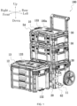
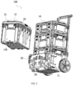
- FIG. 1 shows a toolbox system 100, which may be configured to store an item, such as an accessory, a tool, a charging device, a power supply device, an illumination device, an accessory case/bag, a tool case, and a workbench 50.
- the storage of the item described in the present application is not limited to only the storage of the item in a storage box 10 and also includes fixing the item on an outer side of the storage box 10. Alternatively, hanging, absorbing, and placing the item on the outer side of the storage box 10 are also referred to as the storage of the item in the storage box 10.
- FIG. 1 In the present application, up, down, front, rear, left, and right are defined in FIG. 1 . Unless otherwise specified, up and down, front and rear, and left and right are described below with respect to a state where the toolbox system 100 stands still as shown in FIG. 1 .
- a storage device 100a is a main part forming the toolbox system 100, where the storage device 100a includes at least one storage box 10, and the storage box 10 is formed with an accommodation cavity configured to store the item.
- the toolbox system 100 may include several storage boxes 10, and the storage boxes 10 may be connected to each other. Multiple types of storage boxes 10 are included in the toolbox system 100.
- a container box is included.
- the container box has a box body 132 forming an accommodation cavity, and a top cover 133 basically closing the box body 132.
- a lock switch is disposed between the box body 132 and the top cover 133 so that the box body 132 and the top cover 133 keep fixed relative to each other.
- the box body 132 generally includes a front sidewall, a rear sidewall, a left sidewall, a right sidewall, and a bottom sidewall connected to the preceding four sidewalls.
- Interlocking assemblies 30 are disposed on the top cover 133 of the storage box 10 and can lock storage boxes 10 to each other in an up and down direction.
- a container basket is included.
- the container basket has a box body 132 forming an accommodation cavity.
- the box body 132 is semi-open, that is, no top cover 133 closes the box body 132 and a user can directly fetch the item from the container basket or store the item in the container basket.
- a drawer box 13 is included.
- the drawer box 13 is formed with a box body 132 having an opening on a side and one or more drawers. The user may place the item in the drawer and push the drawer into the box body 132. When the user needs to fetch the item to use it, the user may pull out the drawer and fetch the item to use it.
- the drawer box 13 also includes a structure with a side flap.
- a movable container box is included.
- the movable container box differs from the preceding container box in that the movable container box has a movement assembly, that is, wheels rotatable relative to the ground are connected to a box body 132 and can drive the container box to move.
- the movable container box may also be connected to a handle assembly.
- the handle assembly may be disposed on a side of the movable container box.
- the user may hold the handle assembly to move the movable container box according to an actual situation.
- the storage box 10 in the present application refers to one or a combination of several of the container box, the container basket, the drawer box 13, and the movable container box described above.
- the toolbox system 100 includes at least a first-type storage box 11, a second-type storage box 12, and a first mounting assembly 25.
- Each of the first-type storage box 11 and the second-type storage box 12 has an accommodation cavity where the item can be placed.
- the first mounting assembly 25 can attach the second-type storage box 12 to an outer side of the first-type storage box 11.
- the second-type storage box 12 can move along with the first-type storage box 11.
- the ratio of the volume of the second-type storage box 12 to the volume of the first-type storage box 11 is higher than or equal to 0.3 and lower than or equal to 3.
- the first-type storage box 11 is enabled to be connected to more items.
- the first mounting assembly 25 may be directly formed on the first-type storage box 11 or/and the second-type storage box 12, or the first mounting assembly 25 may be a component independent of the first-type storage box 11 or the second-type storage box 12.
- the attachment includes a direct connection and an indirect connection, and the direct connection includes a point connection, a surface connection, a line connection, and the like.
- the first mounting assembly 25 is directly formed on the first-type storage box 11 or/and the second-type storage box 12 and includes first fitting portions and second fitting portions.
- the first fitting portions are directly formed by the first-type storage box 11, and the second fitting portions are directly formed by the second-type storage box 12.
- the first-type storage box 11 and the second-type storage box 12 keep basically fixed relative to each other.
- the first-type storage box 11 and the second-type storage box 12 can be freely moved relative to each other.
- the first fitting portion may be disposed on a sidewall of the first-type storage box 11, and the second fitting portion may also be disposed on a sidewall of the second-type storage box 12. It is to be noted that it is not defined here which sidewall is specifically provided with the first fitting portion or the second fitting portion.
- the first fitting portion or the second fitting portion may be disposed on any sidewall as long as the connection between the first-type storage box 11 and the second-type storage box 12 can be implemented.
- the first mounting assembly 25 is the component independent of the first-type storage box 11 and the second-type storage box 12.
- the first mounting assembly 25 includes the first fitting portion and the second fitting portion, where the first fitting portion is detachably connected to the sidewall of the first-type storage box 11, and the second fitting portion is detachably connected to the sidewall of the second-type storage box 12.
- the first fitting portion is detachably connected to the sidewall of the first-type storage box 11, and the second fitting portion is directly formed by the second-type storage box 12.
- the first fitting portion is directly formed by the first-type storage box 11, and the second fitting portion is detachably connected to the sidewall of the second-type storage box 12.
- an intermediate member is detachably connected to the first-type storage box 11
- the first mounting assembly 25 is connected to the intermediate member
- the first mounting assembly 25 includes the first fitting portion and the second fitting portion, where the first fitting portion is connected to the intermediate member, and the second fitting portion is connected to the second-type storage box 12.
- a specific structure of the first fitting portion and a specific structure of the second fitting portion are not specifically limited in the present application.
- the following description of the structure of the first fitting portion and the structure of the second fitting portion is one of specific structure manners in which the attachment between the first-type storage box 11 and the second-type storage box 12 can be implemented.
- the toolbox system 100 further includes a second mounting assembly.
- the second mounting assembly can connect the second-type storage box 12 to the top cover of the first-type storage box 11 or the bottom wall of the first-type storage box 11 optionally, which may be understood as follows: the second mounting assembly may mount the second-type storage box 12 to the top cover of the first-type storage box 11, or the second mounting assembly may mount the second-type storage box 12 to the bottom wall of the first-type storage box 11, that is, the second mounting assembly may mount a first storage box 11 to the top cover of the second-type storage box 12.
- the second mounting assembly includes an interlocking assembly including a snap member capable of springing back and a positioning member, where the snap member is connected to the top cover of the first-type storage box 11, and the positioning member is connected to the bottom wall of the second-type storage box 12, or the snap member is connected to the top cover of the second-type storage box 12, and the positioning member is connected to the bottom wall of the first-type storage box 11.
- a third-type storage box may be connected to the top cover of the first-type storage box 11 by the second mounting assembly
- a fourth-type storage box may also be connected to the top cover of the third-type storage box by the second mounting assembly, and the user may connect more storage boxes to the fourth-type storage box.
- the second-type storage box 12 may be connected to the first-type storage box 11, the third-type storage box, or the fourth-type storage box by the first mounting assembly 25, and the first-type storage box 11 may be connected to wheels. In this way, the user may move the first-type storage box 11 so that the second-type storage box 12, the third-type storage box, and the fourth-type storage box can be moved along with the first-type storage box 11.
- the first-type storage box 11, the second-type storage box 12, the third-type storage box, and the fourth-type storage box here are only used for describing the connection manners of the first-type storage box 11, the second-type storage box 12, the third-type storage box, and the fourth-type storage box.
- first-type storage box 11, the second-type storage box 12, the third-type storage box, and the fourth-type storage box may be the same type of storage boxes or may be different types of storage boxes, or part of the storage boxes may be the same type of storage boxes.
- the structure of the first mounting assembly 25 may be consistent with or may be partially consistent with the structure of the second mounting assembly.
- the first mounting assembly 25 may attach the second-type storage box 12 to the sidewall of the first-type storage box 11. That is, when a second storage box 12 is attached to the first-type storage box 11, the second storage box 12 can move along with the first-type storage box 11, and when the second-type storage box 12 is separated from the first-type storage box 11, the first-type storage box 11 and the second-type storage box 12 can be freely moved relative to each other.
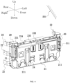
- the toolbox system 100 includes an externally connected assembly 20 disposed outside the accommodation cavity.
- the externally connected assembly 20 may be understood as the intermediate member described above.
- the externally connected assembly 20 is configured such that a tool, an accessory, a charging device, a power supply device, an illumination device, the storage box 10, and the like are externally hung on the externally connected assembly 20.
- the externally connected assembly 20 may be fixedly connected to the first-type storage box 11 in a removable manner.
- the externally connected assembly 20 is provided with one or several positioning holes 211.
- the positioning hole 211 is configured to fixedly connect the externally connected assembly 20 to a to-be-mounted portion 221.
- the to-be-mounted portion 221 may be a wall, the ground, a goods shelf, a wood board, or the like.
- the externally connected assembly 20 is provided with four positioning holes 211.
- a panel 21 of the externally connected assembly 20 is provided with the four positioning holes 211.
- the positioning holes 211 are located at four corners of the panel 21 separately, and the user may cause screws to pass through the preceding positioning holes 211 to fix the externally connected assembly 20 to the to-be-mounted portion 221. If the user needs to remove the externally connected assembly 20 or change the position where the externally connected assembly 20 is mounted, the user only needs to remove the screws from the positioning holes 211 and then needs to remove the externally connected assembly 20 from the to-be-mounted portion 221. If the mounting position needs to be changed, the user only needs to cause the screws to pass through the preceding positioning holes 211 again to fix the externally connected assembly 20 to a new to-be-mounted portion 221.
- the externally connected assembly 20 includes the panel 21, and the panel 21 is disposed on the front side of the externally connected assembly 20.
- Extension members 22 are detachably connected to the externally connected assembly 20 and basically disposed on the rear side of the externally connected assembly 20 to be opposite to the panel 21.
- An extension member 22 is configured to connect the externally connected assembly 20 to the first-type storage box 11.
- the extension member 22 may be connected to the box body 132 of the first-type storage box 11, that is, the extension member 22 is detachably connected to the sidewall of the first-type storage box 11.
- the extension member 22 includes at least one mounting portion 221 and a connecting portion 222, where the mounting portion 221 is configured to be fixedly connected to the externally connected assembly 20, and the connecting portion 222 is configured to be fixedly connected to the first-type storage box 11.
- the mounting portion 221 and the connecting portion 222 are fixedly connected to each other or integrally formed.
- the mounting portion 221 and the connecting portion 222 are integrally formed.
- a connecting segment 57 is disposed at a corner of the first-type storage box 11, and the connecting portion 222 may be connected to the connecting segment 57 of the first-type storage box 11 through one or a combination of several of a screw, a pin, a rivet, and a movable snap 422.
- the connecting segment 57 is formed with a mounting surface
- the connecting portion 222 is formed with through holes
- the user may cause screws to pass through the through holes so that the extension member 22 is fastened on the mounting surface by the connecting portion 222.
- the mounting portion 221 may be connected to the connecting segment 57 of the first-type storage box 11 through one or a combination of several of a screw, a pin, a rivet, and a movable snap 422.
- the mounting portion 221 is U-shaped, that is, the mounting portion 221 has a first mounting plate 2211, a second mounting plate 2212, and a third mounting plate 2213.
- the first mounting plate 2211 and the second mounting plate 2212 are spaced.
- the third mounting plate 2213 connects the first mounting plate 2211 to the second mounting plate 2212.
- the second mounting plate 2212 is connected to the connecting portion 222.
- Each of the first mounting plate 2211 and the second mounting plate 2212 is provided with through holes, and the user may cause bolts 2214 to pass through connecting holes of the mounting portion 221, the through holes of the first mounting plate 2211, and the through holes of the second mounting plate 2212 and then may screw up the bolts 2214 with nuts 2215.
- several extension members 22 may be used for connecting the externally connected assembly 20 to the first-type storage box 11. Unless otherwise indicated, the connecting segment 57 of the storage box 11 also belongs to the sidewall of the storage box 11.
- the extension member 22 further includes an extension portion 223.
- the connecting portion 222 is disposed between the extension portion 223 and the mounting portion 221, and the connecting portion 222, the extension portion 223, and the mounting portion 221 are fixedly connected to each other or integrally formed, for example, the connecting portion 222, the extension portion 223, and the mounting portion 221 are integrally formed.
- the extension portion 223 is configured to mount an external hanger 62.
- the external hanger 62 is configured to connect the tool, the accessory, a fan unit, the charging device, the power supply device, the illumination device, and the like.
- the extension portion 223, the connecting portion 222, and the mounting portion 221 are not in the same plane, are sequentially connected to each other, and are configured to be inclined relative to each other.
- the extension member 22 may be made of a metal material.
- Interlocking assemblies 30 are further included on the externally connected assembly 20 and basically disposed on the front side of the externally connected assembly 20.
- An interlocking assembly 30 is configured to lock the tool, the accessory, the fan unit, the charging device, the power supply device, the illumination device, the workbench 50, and the like.
- An interlocking assembly 30 refers to a removable connection manner between the externally connected assembly 20 and the tool, the accessory, the fan unit, the charging device, the power supply device, the illumination device, the workbench 50, or the like.
- the two may be connected through a snap connection, a threaded connection, a screw connection, adsorption, or the like.
- the two may be connected through a combination of multiple connection manners.
- the snap 422 connection is used. That is, the interlocking assemblies 30 are snap 422 assemblies 31 disposed on two sides of the externally connected assembly 20.
- the snap 422 assemblies 31 on the two sides have structures basically consistent with each other.
- a snap 422 assembly 31 includes a snap 422 member 311 capable of springing back and a positioning member 312.
- the snap 422 member 311 capable of springing back is mounted on the externally connected assembly 20, and the positioning member 312 is disposed on any one of the preceding structures.
- no external force is applied to the snap 422 member 311, and the positioning member 312 and the snap 422 member 311 always keep in close contact with each other. If the user needs to unlock the structure from the externally connected assembly 20, the user only needs to turn the snap 422 member 311 outwards to separate the snap 422 member 311 from the positioning member 312 so that the structure can be unlocked from the externally connected assembly 20.
- the externally connected assembly 20 may be externally connected to support members 23.
- a support member 23 is configured to connect another external hanger 62, a power tool, a power tool accessory, a battery pack, the fan unit, the accessory case/bag, a charger, or the like.
- the support member 23 may be fixedly connected to the panel 21 of the externally connected member 20 in a detachable manner.
- the support member 23 includes a first connecting end 231, a second connecting end 232, and a main support portion 233 connecting the first connecting end 231 to the second connecting end 232.
- the first connecting end 231 and the second connecting end 232 are fixedly connected to the externally connected assembly 20.
- the main support portion 233 and the panel 21 of the externally connected assembly 20 are spaced.
- a hanging slot 234 is formed between the support member 23 and the externally connected assembly 20.
- Another external hanger 62, the power tool, the power tool accessory, the battery pack, the fan unit, the accessory case/bag, the charger, or the like may be hung in the hanging slot 234.
- One or more support members 23 may be disposed on the externally connected assembly 20, and the support members 23 may be disposed side by side. Along a left and right direction, the interlocking assemblies 30 are disposed on two sides of the support members 23.
- the user needs to detach the support members 23 from the externally connected member 20 when the user needs to use the interlocking assemblies 30 to lock the item so that interference to the interlocking assemblies 30 is avoided and the effect on the stability of the connections of the interlocking assemblies 30 is avoided.
- the user may mount the support member 23 to the externally connected assembly 20.
- the externally connected assembly 20 is further connected to hook portions 24.
- a hook portion 24 is connected to the panel 21 of the externally connected assembly 20, and the hook portion 24 is movable relative to the externally connected assembly 20, that is, the hook portion 24 has at least two states during the movement, an unfolded state and a contained state.
- the hook portion 24 is in the unfolded state, the hook portion 24 is in the state of being unfolded, and when the hook portion 24 is in the contained state, the hook portion 24 is in the state of being contained.
- the user may turn the hook portion 24 so that the hook portion 24 is rotatable relative to the panel 21 of the externally connected assembly 20.
- the hook portion 24 includes a body 241 and a rotary portion 242 that are fixedly connected to each other or integrally formed.
- the body 241 may be formed with a bracket 243, and the user may place the item or the like on the body 241.
- the rotary portion 242 is connected to the externally connected assembly 20 and drives the body 241 to rotate relative to the externally connected assembly 20.
- the joint between the rotary portion 242 and the externally connected assembly 20 is basically disposed at the lower end of the externally connected assembly 20, where the body 241 is hollow.
- Recessed accommodation slots 244 are disposed on the panel 21 of the externally connected assembly 20. In this way, when the hook portion 24 is in the contained state, the body 241 can be basically accommodated in an accommodation cavity 244 so that the hook portion 24 does not affect the use of a function of another component on another externally connected assembly 20.
- the hook portion 24 When the user turns the hook portion 24 to the unfolded state, the hook portion 24 is unfolded.
- the body 241 and the panel 21 of the externally connected assembly 20 are approximately at a right angle. That is, the bracket 243 is formed between the body 241 and the externally connected assembly 20, and the user may place the item or the like on the body 241.
- the hook portion 24 may be turned to the contained state. In this case, the hook portion 24 is contained in the accommodation slot 244 of the panel 21.
- two hook portions 24 are disposed on the externally connected assemblies 20.
- the externally connected assembly 20 is connected to the first mounting assembly 25.
- the first mounting assembly 25 is connected to the second-type storage box 12 so that the externally connected assembly 20 and the second-type storage box 12 keep fixed relative to each other.
- the first mounting assembly 25 includes first fitting portions 251 and second fitting portions 252. When a first fitting portion 251 mates with a second fitting portion 252, the externally connected assembly 20 and the second-type storage box 12 keep fixed relative to each other. That is, the first fitting portion 251 may be separated from the second fitting portion 252. When the first fitting portion 251 is separated from the second fitting portion 252, the first-type storage box 11 and the second-type storage box 12 can be freely moved relative to each other.
- the first fitting portion 251 and the externally connected assembly 20 are fixedly connected to each other or integrally formed, and the second fitting portion 252 and the second-type storage box 12 are fixedly connected to each other or integrally formed.
- the first fitting portion 251 and the externally connected assembly 20 are integrally formed
- the second fitting portion 252 and the second-type storage box 12 are integrally formed
- the first fitting portion 251 guides the second fitting portion 252 to slide along a preset direction to a corresponding position and be engaged at the corresponding position so that the externally connected assembly 20 and the second-type storage box 12 keep fixed relative to each other.
- the body of the first fitting portion 251 is approximately T-shaped.
- the first fitting portion 251 has a first stopper portion 2511 and a second stopper portion 2512, where the first stopper portion 2511 and the second stopper portion 2512 mate with the second fitting portion 252 to restrain the second-type storage box 12 from moving along the left and right direction.
- the first fitting portion 251 has a first guide portion 2513 and a third stopper portion 2514, where the first guide portion 2513 is configured to guide the second fitting portion 252 to slide along the preset direction 101, and the third stopper portion 2514 mates with the second fitting portion 252 to restrain the second-type storage box 12 from moving downwards.
- the second fitting portion 252 is an engagement slot that is approximately U-shaped.
- the second fitting portion 252 includes a first stopper slot 2521 and a second stopper slot 2522.
- first stopper portion 2511 and the second stopper portion 2512 are engaged with the first stopper slot 2521 and the second stopper slot 2522 so that the second-type storage box 12 is restrained from moving in the left and right direction.
- each of the first stopper slot 2521 and the second stopper slot 2522 is approximately U-shaped, that is, the first stopper portion 2511 and the second stopper portion 2512 are engaged with the first stopper slot 2521 and the second stopper slot 2522, and the first stopper slot 2521 and the second stopper slot 2522 can simultaneously restrain the second-type storage box 12 from moving in a front and rear direction.
- the second fitting portion 252 further includes a third stopper slot 2523 disposed between the first stopper slot 2521 and the second stopper slot 2522. When the second fitting portion 252 is engaged with the first fitting portion 251, the third stopper slot 2523 mates with the third stopper portion 2514 to restrain the second-type storage box 12 from moving downwards.
- the user When the user needs to mount the second-type storage box 12 to the externally connected assembly 20, the user only needs to slide the second fitting portion 252 on the second-type storage box 12 downwards to engage the second fitting portion 252 with the first fitting portion 251 of a mounting plate so that the connection between the second-type storage box 12 and the externally connected assembly 20 can be implemented.
- the user When the user needs to detach the second-type storage box 12 from the externally connected assembly 20, the user only needs to lift the second-type storage box 12 upwards relative to the externally connected assembly 20 so that the second-type storage box 12 can be separated from the externally connected assembly 20.
- the stability of the connection between the externally connected assembly 20 and the second-type storage box 12 can be effectively ensured, and in another aspect, it is convenient for the user to mount or detach the storage boxes 10.
- the first-type storage box 11 and the second-type storage box 12 do not refer to particular storage boxes 10 but are only intended to indicate that the externally connected assembly 20 can implement the function of simultaneously fixing two storage boxes 10 side by side.
- the first-type storage box 11 and the second-type storage box 12 may be the same type of storage boxes 10 or different types of storage boxes 10.
- first fitting portions 251 are disposed on the externally connected assembly 20 and multiple second fitting portions 252 mating with the first fitting portions 251 are also disposed on the storage box 10 so that the stability of the connection between the externally connected assembly 20 and the storage box 10 is ensured.
- at least two rows of first fitting portions 251 are disposed on the externally connected assembly 20, and two rows of first fitting portions 251 are disposed on the upper side and lower side of the externally connected assembly 20 separately.
- the storage box 10 may be optionally connected to the first fitting portions 251 on the upper side or may be connected to the first fitting portions 251 on the lower side. The user may select a mounting position according to the actual situation.
- the preceding structure is not limited to the storage box 10 and may be another item. That is, the second fitting portion 252 is connected to the item so that the item can be connected to the externally connected assembly 20.
- the externally connected assembly 20 may be fixedly connected to the movable container box by the extension members 22.
- the user can cause, in one aspect, the externally connected assembly 20 to move along with the movable container box.
- the user when the user connects the storage box 10 to the externally connected assembly 20, the user can push/pull the movable container box to enable the storage box 10 to move along with the movable container box or can connect tools, accessories, and the like to the support members 23.
- the user may turn the hook portions 24 to cause them to be in the unfolded state.
- the combination of the externally connected assembly 20 with the movable container box can approximately form a "forklift truck", and the user may place the item on the "forklift truck".
- a rope may be used to pass through the body 241 of each of the hook portions 24 and tie the item simultaneously.
- the rope is fixed on the handle assembly, or of course, the rope may be fixed at another position as long as it is ensured that the item is fixed on the "forklift truck”.
- the user may detach the extension members 22 from the externally connected assembly 20, fix the externally connected assembly 20 on the wall by using screws, and connect corresponding items to the externally connected assembly 20 according to needs.
- the panel 21 of the externally connected assembly 20 is constituted by multiple small panels.
- Each small panel is fixedly connected to or integrally formed with one or several first fitting portions 251, where one or more small panels may be provided.
- the number of small panels constituting the panel 21 is not limited as long as the connection to the preceding structure can be implemented.
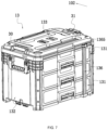
- the drawer box 13 includes a layered box 131 and the box body 132.
- the drawer box 13 may be provided with one or more layered boxes 131 according to different needs.
- the layered box 131 is disposed in the box body 132 and may reciprocate along rails disposed in the box body 132.
- Interlocking assemblies 30 are disposed on the upper side of the drawer box 13, that is, the drawer box 13 may be stacked on the storage box 10.
- the drawer box 13 may be interlocked with the movable container box.
- the drawer box 13 can be driven to move along with the movable container box.
- another item or the storage box 10 may be stacked on the drawer box 13.
- the three-layer drawer box 13 shown in FIG. 1 is used as an example, and the three-layer drawer box 13 may be understood as a drawer box 13 with three layered boxes 131.
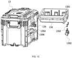
- the drawer box 13 includes rail assemblies 134.
- a rail assembly 134 is disposed on two sides of each layered box 131 and configured to guide each layered box 131 to reciprocate along a first direction 102.
- Each layered box 131 can independently slide relative to the box body 132.
- the drawer box 13 further includes connecting assemblies 135.
- a connecting assembly 135 is configured to cause the layered box 131 and the box body 132 to keep fixed to each other so that the layered box 131 is prevented from sliding out of the box body 132 without being driven by an external force.
- the layered box 131 slides out of the box body 132, resulting in that the item placed in the box body 132 falls.
- the layered box 131 has a locked state and an unlocked state relative to the box body 132.
- the layered box 131 and the box body 132 keep fixed relative to each other without being driven by the external force.
- the layered box 131 is in the unlocked state, the layered box 131 can slide backwards and forwards along the first direction 102 without being separated from the box body 132.
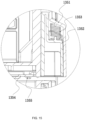
- the connecting assembly 135 includes a first stopper member 1351, a second stopper member 1352, biasing members 1353, and a locking member 1354.
- the locking member 1354 and the box body 132 are fixedly connected to each other or integrally formed.
- the locking member 1354 and the second stopper member 1352 can mate with each other so that the layered box 131 and the box body 132 keep fixed relative to each other.
- the biasing members 1353 are disposed between the second stopper member 1352 and the first stopper member 1351 and always apply downward biasing forces to the second stopper member 1352.
- the first stopper member 1351 and the layered box 131 are fixedly connected to each other or integrally formed.
- a locking portion 1356 is formed on the locking member 1354, and an engagement portion 1355 is disposed on the second stopper member 1352.
- the locking portion 1356 mates with the engagement portion 1355, the layered box 131 is in the locked state, and when the locking portion 1356 is separated from the engagement portion 1355, the layered box 131 is in the unlocked state.
- the first stopper member 1351 and the layered box 131 are integrally formed.
- the layered box 131 is formed with an accommodation cavity
- the biasing members 1353 are disposed in the accommodation cavity
- the second stopper member 1352 is at least partially disposed in the accommodation cavity and can synchronously move along with the first stopper member 1351, and one end of a biasing member 1353 abuts against the layered box 131 and the other end of the biasing member 1353 abuts against the second stopper member 1352.
- the biasing members 1353 are provided with preload so that the biasing members 1353 always apply the downward biasing forces to the second stopper member 1352.
- the biasing forces cause the locking portion 1356 and the engagement portion 1355 to always keep mating with each other when the layered box 131 is in the locked state.
- the locking portion 1356 is disposed on the movement path of the engagement portion 1355, the locking portion 1356 may be a hole, the engagement portion 1355 is a downward protrusion on the second stopper member 1352, and the biasing forces applied to the second stopper member 1352 by the biasing members 1353 cause the protrusion to always keep engaged in the hole without being affected by an external force.
- the protrusion is engaged in the hole.
- the user only needs to apply an upward force to the second stopper member 1352 to overcome the biasing forces so that the protrusion is separated from the hole, and the layered box 131 can slide out of the box body 132.
- the drawer box 13 has the three layered boxes 131, and each of the three layered boxes 131 may be locked to the box body 132 in the preceding manner. The details are not repeated here.
- two biasing members 1353 may be provided.
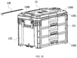
- the drawer box 13 further includes a locking plate 136 that can prevent the layered boxes 131 from sliding out of the box body 132
- the locking plate 136 is disposed on the front side of the drawer box 13 and passes all the layered boxes 131 of the drawer box 13.
- Two hollow protrusions are formed on the front box body 132 of the drawer box 13, which are a first protrusion portion 1361 and a second protrusion portion 1362 separately.
- the first protrusion portion 1361 and the second protrusion portion 1362 are spaced from each other.
- the locking plate 136 can be inserted into the first protrusion portion 1361 and the second protrusion portion 1362.
- the first protrusion portion 1361 and the second protrusion portion 1362 are disposed on two sides of all the layered boxes 131 of the drawer box 13.
- the locking plate 136 is elongated. With this configuration, after the locking plate 136 is inserted into the first protrusion portion 1361 and the second protrusion portion 1362, the locking plate 136 can better prevent the layered boxes 131 from sliding out of the box body 132, ensuring the stability of the connection between the layered boxes 131 and the box body 132.
- the locking plate 136 includes an elongated portion 1363 and a bent portion 1364.
- the elongated portion 1363 and the bent portion 1364 are fixedly connected to each other or integrally formed.
- the elongated portion 1363 and the bent portion 1364 are configured to be inclined.
- the elongated portion 1363 and the bent portion 1364 are configured to be at a right angle.
- the locking plate 136 is inserted downwards into the first protrusion portion 1361 and the second protrusion portion 1362 until the locking plate 136 stops moving downwards after the bent portion 1364 is in contact with the first protrusion portion 1361.
- the first protrusion portion 1361 and the bent portion 1364 are further formed with corresponding locking holes 1365.
- the user may lock the locking plate 136 and the box body 132 with a padlock so that the stability of the connection between the layered boxes 131 and the box body 132 is further ensured and thefts can be prevented.
- the box body 132 is formed with a container slot 1366.
- the container slot 1366 is configured to be used for the placement of the locking plate 136. That is, when the user does not need the locking plate 136, the locking plate 136 may be placed in the container slot 1366 so that it is convenient for the user to use the locking plate 136 next time.
- the box body 132 is provided with the container slot 1366, and the locking plate 136 may be inserted into the container slot 1366 along a direction.
- the container slot 1366 may be disposed on the upper side or upper side of the layered boxes 131. Thus, the locking plate 136 does not interfere with the layered boxes 131 when the user inserts the locking plate 136 into the container slot 1366.
- the container box 1366 may be formed on a side surface of the box body 132.
- the user may directly insert the locking plate 136 into the container slot 1366 on the side surface.
- the container slot 1366 may be disposed on any side surface of the box body 132 except the side surface on which the layered boxes 131 are drawn out.
- FIGS. 16 to 19 show a foldable bracket table 40, where the bracket table 40 includes at least one support member 41 that may be configured to be used for the placement of the items, the storage boxes 10, and the like.
- the bracket table 40 may be fixed to a wall, the ground, a goods shelf, a wood board, or adjustment guide rails 42.
- the bracket table 40 further includes mounting assemblies 43 connected to the support member 41.
- a mounting assembly 43 includes a first connector 435 connected to the support member 41.
- the support member 41 has a first state and a second state relative to the first connector 435. When the support member 41 is in the first state, the support member 41 is at a first position, and in this case, the user may place the items, the storage boxes 10, and the like on the support member 41. When the support member 41 is in the second state, the support member 41 is at a second position, and in this case, the support member 41 and the adjustment guide rails 42 occupy a relatively small space. If the user does not use the support member 41 for placing the items, the storage boxes 10, and the like, the support member 41 may be in the second state, thereby reasonably using a space.
- the support member 41 has at least two positions relative to the first connector 435. That is, the included angle ⁇ between the support member 41 at the first position and the support member 41 at the second position is greater than or equal to 30 degrees (as shown in FIG. 23 ).
- a first connector 435a is rotatably connected to a to-be-connected portion 47, and a support member 41a is rotatably connected to the to-be-connected portion 47.
- the first connector 435a abuts against the support member 41a, and the first connector 435a and the support member 41a keep fixed relative to each other.
- the support member 41a is in the second state, the first connector 435a is separated from the support member 41a. In this case, the support member 41a loses support. Affected by gravity, the other end of the support member 41a connected to the to-be-connected portion 47 falls down.
- the first connector 435a may be connected to the support member 41a through one or a combination of several of a threaded connection, a mortise and tenon connection, a screw connection, a pin connection, and a snap connection.
- the connection manner between the first connector 435a and the support member 41a is not limited here as long as a detachable connection between the first connector 435a and the support member 41a can be implemented.
- the to-be-connected portion 47 may be one of the wall, the ground, the goods shelf, and the wood board. That is to say, the first connector 435a and the support member 41a can be directly mounted to one or a combination of several of the wall, the ground, the goods shelf, and the wood board.
- the to-be-connected portion 47 is detachably connected to the wall, the ground, the goods shelf, and the wood board.
- the bracket table 40 is mounted to the adjustment guide rails 42.
- the mounting assemblies 43 are connected to the adjustment guide rails 42.
- the number of the adjustment guide rails 42 is two.
- the number of the mounting assemblies 43 fixedly connected to the adjustment guide rails 42 is also two.
- the two mounting assemblies 43 are connected to the support member 41.
- the adjustment guide rails 42 and the mounting assemblies 43 are basically disposed symmetrically. That is to say, the structures of the adjustment guide rails 42 and the mounting assemblies 43 are basically consistent with each other. To avoid the repetition of the details, only one group of structures is used as an example for description here.
- the mounting assembly 43 includes a third connector 431, positioning pins 432, a resilient member 433, a driving member 434, first connectors 435, a second connector 436, and fasteners 437.
- the user may engage the engagement slots 421 on the second connector 436 with the snaps 422 and then may use the fasteners 437 to pass through the through holes of the second connector 436 and the through holes of the adjustment guide rail 42 to fix the second connector 436 and the adjustment guide rail 42.
- the second connector 436 prevented from moving freely, but also the stability of the connection between the second connector 436 and the adjustment guide rail 42 is ensured.
- the bracket table 40 is mounted on the adjustment guide rails 42, the second connector 436 is mounted on the adjustment guide rail 42, and the bracket table 40 can be folded relative to the adjustment guide rail 42, which may be understood as follows: the support member 41 can be unfolded or folded relative to the second connector 436. That is, the support member 41 also has a first state and a second state relative to the second connector 436. When the support member 41 is in the first state, an angle ⁇ at which the support member 41 intersects with the second connector 436 is greater than or equal to 80 degrees and less than or equal to 100 degrees. In this case, the user can place the items, the storage boxes 10, and the like on the support member 41.
- the first connector 435 connects the second connector 436 to the third connector 431 and is rotatable relative to the second connector 436.
- Two first connectors 435 may be provided, and two ends of each of the two first connectors 435 are each connected to the positioning pins 432. That is, the two first connectors 435 are connected to the second connector 436 and the third connector 431 by the positioning pins 432.
- the first connectors 435 are disposed on two sides of the second connector 436, and the positioning pins 432 pass through the first connectors 435. With this configuration, the first connectors 435 are caused to be rotatable relative to the second connector 436.
- the third connector 431 is fixedly connected to the support member 41.
- the third connector 431 is rotatably connected to the second connector 436, that is, the third connector 431 is rotatable about a first rotation axis 103.
- the third connector 431 is formed with a hollow slideway 439.
- the other ends of the first connectors 435 are disposed on two sides of the slideway 439. That is, a positioning pin 432 passes through the first connectors 435 and the slideway 439 to connect the first connectors 435 to the third connector 431.
- the slideway 439 has a front edge 45 and a rear edge 46 that are disposed on two sides of the slideway 439. Since the slideway 439 has a certain length, the positioning pin 432 is slidable in the slideway 439 without being driven by an external force, which may be understood as follows: the positioning pin 432 is slidable between the front edge 45 and the rear edge 46. The front edge 45 is farther from the first rotation axis 103 than the rear edge 46.
- the resilient arm 44 Since the resilient arm 44 always applies the thrust to the driving member 434, the preceding thrust causes one end of the driving member 434 to be always in contact with the third connector 431 in the case where the driving member 434 is not driven by an external force.
- the positioning pin 432 connected to the first connector 435 is slidable in the slideway 439. In the process where the positioning pin 432 slides, the rear end of the driving member 434 abuts against the positioning pin 432 and restrains the movement of the positioning pin 432. Without being driven by an external force, the driving member 434 always abuts against the third connector 431. That is to say, the rear end of the driving member 434 always abuts against the positioning pin 432 so that the positioning member 41 is in the first state.
- the user needs to cause the support member 41 to be in the second state, the user only needs to press the driving member 434 to overcome the thrust applied to the driving member 434 by the resilient arm 44 so that the rear end of the driving member 434 is separated from the positioning pin 432.
- the positioning pin 432 can continue sliding in an opposite direction in the slideway 439.
- the first connector 435 does not abut against the third connector 431, and affected by gravity, the front end of the third connector 431 approaches the second connector 436, that is, the support member 41 is folded downwards to be in the second state. If the user needs to cause the support member 41 to be in the first state, the user only needs to apply a force to lift one end of the support member 41 upwards.
- the third connector 431 fixedly connected to the support member 41 is lifted upwards about the first rotation axis 103.
- the positioning pin 432 slides rearwards in the slideway 439 to be in contact with the driving member 434 for the first time.
- the user continues applying the force to the support member 41, the force is transferred to the positioning pin 432 so that the positioning pin 432 overcomes the thrust applied to the driving member 434 by the resilient arm 44 and continues moving rearwards to the rear edge 46 of the slideway 439.
- the thrust applied to the driving member 434 by the resilient arm 44 causes the rear end of the driving member 434 to be restored to the state of abutting against the third connector 431.
- the user removes the force applied to the support member 41, the third connector 431, the first connector 435, the positioning pin 432, and the like are affected by gravity to move downwards. That is, the positioning pin 432 moves forwards in the slideway 439 until the positioning pin 432 abuts against the rear end of the driving member 434, thereby causing the positioning pin 432, the third connector 431, the first connectors 435, and the support member 41 to be kept at current positions. In this case, the user completes switching the states, and the support member 41 is in the first state.
- the adjustment guide rail 42 is longer than the second connector 436. That is to say, multiple mounting assemblies 43 may be mounted on the adjustment guide rail 42. That is, multiple bracket tables 40 may be connected to the adjustment guide rail 42, and items, storage boxes 10, and the like may be placed on support members 41. With this configuration, the space in a length direction can be reasonably used so that the items, the storage boxes 10, and the like are prevented from being placed on the ground randomly to cause unreasonable use of the space.
- the bracket table 40 may be directly connected to the wall. That is to say, the second connector 436 may be directly mounted to the wall. In this way, the user can hang the items, the storage boxes 10, and the like on the wall.
- the present application provides the bracket table 40 having two states. When the bracket table 40 is in an unfolded state, the bracket table 40 can be interlocked with the storage box 10. When the user does not need the bracket table 40, the bracket table 40 may be caused to be in the folded state.
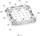
- FIG. 3 , FIG. 5 , FIG. 11 , FIG. 12 , and FIG. 17 show a workbench 50.
- the workbench 50 may be configured to be used for the placement of tools such as a table saw.
- the workbench 50 may be used as a panel 21 by the user, and the user can do work on the workbench 50.
- the workbench 50 is approximately quadrilateral.
- the workbench 50 may be connected to the bracket table 40.
- Snap 422 members 311 capable of springing back are disposed on the support member 41.
- Positioning members 312 mating with the snap 422 members 311 are connected to the workbench 50.
- the snap 422 members 311 and the positioning members 312 in this example may refer to the preceding interlocking assemblies 30.
- snap 422 members 311 are also disposed on the externally connected assembly 20, and the user may engage the positioning members 312 with the snap 422 members 311 so that the externally connected member 20 and the workbench 50 keep fixed relative to each other.
- the toolbox system 100 further includes the first mounting assembly 25 connected to the first-type storage box 11.
- the first mounting assembly 25 can connect the first storage box 11 to the workbench 50 and attach the workbench 50 to the sidewall of the first-type storage box 11.
- the first mounting assembly 25 refers to a removable connection manner between the workbench 50 and the first-type storage box 11.
- the workbench 50 and the first-type storage box 11 may be connected to each other through a snap connection, a threaded connection, a screw connection, adsorption, a hook connection, an interference connection, or a combination of multiple connection manners of course.
- the workbench 50 has a first connection state and a second connection state. When the workbench 50 is in the first connection state, the workbench 50 is attached to the top cover of the storage box 10. When the workbench 50 is in the second connection state, the workbench 50 is attached to a sidewall of the storage box 10. That is, the workbench 50 may be connected to the outer side of the storage box 10.
- the workbench 50 may be connected to the storage box 10. That is, contact surfaces 531 are connected to the workbench 50, connecting surfaces 541 at least in partial contact with the contact surfaces 531 are connected to the storage box 10, and the workbench 50 is movable along with the storage box 10 when the contact surfaces 531 are in contact with the connecting surfaces 541.
- the workbench 50 may be connected to the top cover 133 of the storage box 10. Inserting portions 53 are connected to the workbench 50, and inserted portions 54 are connected to the top cover 133 of the storage box 10. The inserted portions 54 form the connecting surfaces 541, and the inserting portions 53 form the contact surfaces 531. The inserting portions 53 may be directly inserted into the inserted portions 54, thereby keeping the workbench 50 and the storage box 10 fixed relative to each other.
- the workbench 50 includes a front end surface 51 and a rear end surface 52 that are disposed opposite to each other. The front end surface 51 may be used by the user to work, place a table saw, or the like. At least one raised inserting portion 53 is formed on the rear end surface 52.
- the four inserting portions 53 are formed on the rear end surface 52 and disposed at the four corners of the rear end surface 52 separately.
- the top cover 133 of the storage box 10 is formed with the recessed inserted portions 54 corresponding to the inserting portions 53.
- the inserted portions 54 are disposed at the four corners of the top cover 133 separately.
- the snap 422 members 311 capable of springing back are disposed on the top cover 133 of the storage box 10.
- the positioning members 312 may also be disposed on the storage box 10. For example, the positioning members 312 are disposed at the lower end of the storage box 10. In this way, the user may interlock multiple storage boxes 10 together and insert the workbench 50 into the top cover 133 of the uppermost storage box 10.
- the user may use the multiple storage boxes 10 and the workbench 50 as a table. For example, in some construction sites, the multiple storage boxes 10 and the workbench 50 may be used as the table.
- the workbench 50 may be connected to the movable container box.
- the user stacks the storage box 10 on the movable container box to adjust the height.
- the storage box 10 and the movable container box can form a movable stable, and the user can do the work on the workbench 50.
- the user may place the table saw on the workbench 50 and use a rope to tie the table saw to prevent the table saw from falling. In this way, the space in the storage box 10 can be saved so that more items are placed in the storage box 10.
- Hanging portions 55 may also be connected to the workbench 50.
- the hanging portions 55 and the workbench 50 are fixedly connected to each other or integrally formed.
- the hanging portions 55 are disposed on the rear end surface 52 of the workbench 50.
- At least one hanging portion 55 may be disposed on the workbench 50.
- the two hanging portions 55 are disposed on the workbench 50. The user can hang, through the hanging portions 55, the workbench 50 to any position to which the workbench 50 can be hung.
- the workbench 50 further includes storage slots 56 disposed on the front end surface 51.
- the storage slots 56 are disposed around the front end surface 51.
- the toolbox system 100 further includes an externally hanging assembly 60 including an intermediate member 61 and the external hanger 62.
- the external hanger 62 can be detachably connected to the item.
- the external hanger 62 includes a battery pack hanger, a cable hanger, a scale hanger, a power tool hanger, an accessory hanger, and the support member 23, which may configured to be used for separately hanging the battery pack, a cable, s scale, the power tool, the accessory, and the like.
- Multiple external hangers 62 may be disposed on the storage box 10.
- the external hanger 62 may be one of or a combination of the battery pack hanger, the cable hanger, the scale hanger, the support member 23, and the power tool hanger.
- the intermediate member 61 is fixedly connected to the workbench 50 in a detachable manner. That is, the intermediate member 61 may be connected to the workbench 50 through one or a combination of several of a screw, a pin, a rivet, and a movable snap 422.
- the intermediate member 61 is connected to a connecting segment 57 of the workbench 50. That is, the intermediate member 61 may be mounted on each of the four connecting segments 57 of the workbench 50.
- the support member 23 may be mounted between two intermediate members 61, and the user can hang the tool and the like on the support member 23.
- the user may detach the externally hanging assembly 60 connected to the outer edge of the workbench 50 and connect the externally hanging assembly 60 to the connecting segments 57 of the storage box 10 according to the needs.
- the user connects the externally hanging assembly 60 to the connecting segment 57 of the storage box 10.
- the workbench 50 may be hung, through the hanging portion 55, on a slot formed by the externally hanging assembly 60. In this way, the workbench 50 may be attached to the sidewall of the storage box 10.
Landscapes
- Engineering & Computer Science (AREA)
- Mechanical Engineering (AREA)
- Workshop Equipment, Work Benches, Supports, Or Storage Means (AREA)
- Packaging Frangible Articles (AREA)
Abstract
Description
- This application claims priority to
Chinese Patent Application No. 202211251819.6 Chinese Patent Application No. 202222702569.5 filed with the China National Intellectual Property Administration (CNIPA) on Oct. 13, 2022 - The present application relates to a bracket table applicable to a storage box.
- Since a storage box has an accommodation space, tools are usually placed in the storage box, for example, a battery pack, a horizontal scale, a cable, chemicals such as lubricating oil, and a tool worn at any time. When a user does not use the tools, the storage box is usually placed in a warehouse. However, if storage boxes are all stacked together, the user usually needs to remove toolboxes stacked on the lowermost storage box when the user needs to search for tools placed in the lowermost storage box. Thus, the lowermost storage box can be opened. It is very inconvenient for the user to fetch the tools.
- The present application provides a bracket table that can be interlocked with a storage box.
- The present application provides a bracket table applicable to a storage box. The bracket table applicable to the storage box includes: at least one support member configured to be interlocked with the storage box; and a mounting assembly connected to the support member. The mounting assembly includes a first connector connected to the support member, where the support member has at least a first state and a second state relative to the first connector, where in the case where the support member is in the first state, the support member is at a first position, and in the case where the support member is in the second state, the support member is at a second position.
- As an optional example, the first connector is mounted to at least one of a wall, the ground, a goods shelf, and a wood board.
- As an optional example, the bracket table further includes an interlocking assembly, where in the case where the support member is in the first state, the interlocking assembly is configured to mount at least one of a tool, an accessory, a fan unit, a charging device, a power supply device, an illumination device, a storage box, and a workbench to the support member.
- As an optional example, the first connector is connected to the support member through at least one of a threaded connection, a mortise and tenon connection, a screw connection, a pin connection, and a snap connection so that the support member is kept at the first position.
- As an optional example, the included angle between the support member at the first position and the support member at the second position is greater than or equal to 30 degrees.
- As an optional example, the mounting assembly further includes a second connector rotatably connected to the first connector and a third connector connected to the second connector, where the third connector is rotatably connected to the second connector, and the support member is mounted on the third connector.
- As an optional example, the second connector is mounted to at least one of a wall, the ground, a goods shelf, and a wood board.
- As an optional example, in the case where the support member is at the second position, the included angle between the support member and the second connector is less than 80 degrees.
- As an optional example, the bracket table further includes an adjustment guide rail detachably connected to the mounting assembly, where the second connector is mounted to the adjustment guide rail.
- As an optional example, multiple snaps are disposed on the adjustment guide rail, and multiple engagement slots are disposed on the second connector, where an engagement slot is engaged with a respective snap, and the number of the multiple snaps on the adjustment guide rail is greater than the number of the multiple engagement slots on the second connector so that the engagement slot on the second connector is engaged with different snaps.
- As an optional example, the mounting assembly further includes positioning pins, a resilient member, a driving member, and fasteners, where the fasteners pass through through holes of the second connector and through holes of the adjustment guide rail to fixedly connect the second connector to the adjustment guide rail, the first connector connects the second connector to the third connector, two ends of the first connector are each connected to the positioning pins, the third connector is formed with a slideway that is hollow, a positioning pin is configured to move on the slideway, the third connector is fixedly connected to the support member, the resilient member and the driving member are each connected to the third connector, the resilient member has a resilient arm, and the resilient arm is configured to always apply a thrust to the driving member so that an end of the driving member is always in contact with the third connector.
- As an optional example, the bracket table further includes an interlocking assembly, where in the case where the support member is at the first position, the interlocking assembly is configured to mount at least one of a tool, an accessory, a fan unit, a charging device, a power supply device, an illumination device, a storage box, and a workbench to the support member.
- As an optional example, the interlocking assembly includes a snap assembly including a snap member capable of springing back and a positioning member, where the snap member is connected to the support member, and the positioning member is configured to be disposed on any one of the tool, the accessory, the fan unit, the charging device, the power supply device, the illumination device, the storage box, and the workbench.
- As an optional example, the number of mounting assemblies is two, and the number of adjustment guide rails is two.
- A bracket table applicable to a storage box includes: at least one support member configured to be interlocked with the storage box; and a mounting assembly connected to the support member. The mounting assembly includes a first connector connected to the support member, where the support member has a first position and a second position, where the included angle between the support member at the first position and the support member at the second position is greater than or equal to 30 degrees.
- A toolbox system includes: a first-type storage box having an accommodation cavity, where the accommodation cavity is configured to store an item; a second-type storage box configured to store an item; and a first mounting assembly connected to the first-type storage box. The first mounting assembly is connected to a first storage box and a second storage box and configured to attach the second-type storage box to a sidewall of the first-type storage box.
- As an optional example, the toolbox system further includes a second mounting assembly, where the second mounting assembly is configured to connect the second-type storage box to the top cover of the first-type storage box or the bottom wall of the first-type storage box.
- As an optional example, the first mounting assembly includes a first fitting portion and a second fitting portion, where in the case where the first fitting portion mates with the second fitting portion, the first-type storage box and the second-type storage box keep basically fixed relative to each other, and in the case where the first fitting portion is separated from the second fitting portion, the first-type storage box and the second-type storage box are freely moved relative to each other.
- As an optional example, the toolbox system further includes an externally connected assembly detachably connected to the first-type storage box, where the first fitting portion and the externally connected assembly are connected to each other or integrally formed, and the second fitting portion and the second-type storage box are connected to each other or integrally formed.
- As an optional example, the toolbox system further includes an extension member detachably connected to the externally connected assembly, where the extension member includes a mounting portion, a connecting portion, and an extension portion.
- The mounting portion is connected to the externally connected assembly, the connection portion is connected to the first-type storage box, and the extension portion is configured to mount an external hanger. The extension portion, the connecting portion, and the mounting portion are sequentially connected to each other, and none of the extension portion, the connecting portion, and the mounting portion are in the same plane.
- As an optional example, the externally connected assembly is connected to an interlocking assembly, where the interlocking assembly is configured to lock one of a tool, an accessory, a fan unit, a charging device, a power supply device, an illumination device, and a workbench to a panel of the externally connected assembly. The interlocking assembly includes a snap assembly including a snap member capable of springing back and a positioning member, where the snap member is connected to the panel, and the positioning member is configured to be disposed on any one of the tool, the accessory, the fan unit, the charging device, the power supply device, the illumination device, and the workbench.
- As an optional example, the second mounting assembly includes an interlocking assembly including a snap member capable of springing back and a positioning member, where the snap member is connected to the top cover of the first-type storage box, and the positioning member is connected to the bottom wall of the second-type storage box, or the snap member is connected to the top cover of the second-type storage box, and the positioning member is connected to the bottom wall of the first-type storage box.
- As an optional example, the toolbox system further includes a support member, where the support member is detachably connected to the externally connected assembly and includes a first connecting end, a second connecting end, and a main support portion connecting the first connecting end to the second connecting end, and the externally connected assembly includes at least one panel, where the first connecting end and the second connecting end are connected to the panel, the main support portion and the panel are spaced, and a hanging slot is formed between the main support portion and the panel.
- As an optional example, the externally connected assembly is further connected to a hook portion, where the hook portion is configured to move relative to the panel and has at least an unfolded state and a folded state during the movement.
- As an optional example, the panel of the externally connected assembly is provided with at least one positioning hole configured to fixedly connect the externally connected assembly to a to-be-mounted portion.
- As an optional example, the to-be-mounted portion is at least one of a wall, the ground, a goods shelf, and a wood board.
- As an optional example, the toolbox system further includes a workbench, where the workbench has a first connection state and a second connection state. In the case where the workbench is in the first connection state, the workbench is attached to the top cover of the first-type storage box, and in the case where the workbench is in the second connection state, the workbench is attached to the sidewall of the first-type storage box.
- A toolbox system includes: a first-type storage box having an accommodation cavity, where the accommodation cavity is configured to store an item; a workbench configured to be used for the placement of an item; and a first mounting assembly connected to the first-type storage box. The first mounting assembly is connected to a first storage box and the workbench and configured to attach the workbench to a sidewall of the first-type storage box.
-
-
FIG. 1 is a schematic view of a toolbox system; -
FIG. 2 is a schematic view showing that a storage box and an externally connected assembly inFIG. 1 are separated from each other; -
FIG. 3 is a schematic view showing that a workbench and a storage box in a toolbox system are separated from each other; -
FIG. 4 is a perspective view of an externally connected assembly inFIG. 1 in a folded state; -
FIG. 5 is a perspective view of an externally connected assembly inFIG. 1 in an unfolded state; -
FIG. 6 is an exploded view of a partial structure of an externally connected assembly inFIG. 1 ; -
FIG. 7 is a perspective view of a drawer box in a toolbox system; -
FIG. 8 is a sectional view of the drawer box inFIG. 7 taken along an A-A direction; -
FIG. 9 is a schematic view showing that a locking plate and the drawer box inFIG. 7 are separated from each other; -
FIG. 10 is an exploded view of a connecting assembly of the drawer box inFIG. 7 ; -
FIG. 11 is a perspective view of the workbench inFIG. 3 ; -
FIG. 12 is a schematic view of the workbench inFIG. 11 from another perspective; -
FIG. 13 is a partial enlarged view ofFIG. 2 ; -
FIG. 14 is a partial enlarged view ofFIG. 5 ; -
FIG. 15 is a partial enlarged view ofFIG. 8 ; -
FIG. 16 is a perspective view of a bracket table in a toolbox system, where a support member is in a first state; -
FIG. 17 is a perspective view of a bracket table in a toolbox system, where a support member is in a second state; -
FIG. 18 is a view showing that partial structures of the bracket table inFIG. 16 are separated from each other; -
FIG. 19 is an exploded view of partial structures of the bracket table inFIG. 16 ; -
FIG. 20 is an exploded view of a connecting assembly of the drawer box inFIG. 7 ; -
FIG. 21 is a schematic view of a bracket table; -
FIG. 22 is a schematic view showing that a workbench is attached to a sidewall of a storage box; and -
FIG. 23 is a simplified diagram of a bracket table in a first state and a second state. - Before any examples of this application are explained in detail, it is to be understood that this application is not limited to its application to the structural details and the arrangement of components set forth in the following description or illustrated in the above drawings.
- In this application, the terms "comprising", "including", "having" or any other variation thereof are intended to cover an inclusive inclusion such that a process, method, article or device comprising a series of elements includes not only those series of elements, but also other elements not expressly listed, or elements inherent in the process, method, article, or device. Without further limitations, an element defined by the phrase "comprising a ..." does not preclude the presence of additional identical elements in the process, method, article, or device comprising that element.
- In this application, the term "and/or" is a kind of association relationship describing the relationship between associated objects, which means that there can be three kinds of relationships. For example, A and/or B can indicate that A exists alone, A and B exist simultaneously, and B exists alone. In addition, the character "/" in this application generally indicates that the contextual associated objects belong to an "and/or" relationship.
- In this application, the terms "connection", "combination", "coupling" and "installation" may be direct connection, combination, coupling or installation, and may also be indirect connection, combination, coupling or installation. Among them, for example, direct connection means that two members or assemblies are connected together without intermediaries, and indirect connection means that two members or assemblies are respectively connected with at least one intermediate members and the two members or assemblies are connected by the at least one intermediate members. In addition, "connection" and "coupling" are not limited to physical or mechanical connections or couplings, and may include electrical connections or couplings.
- In this application, it is to be understood by those skilled in the art that a relative term (such as "about", "approximately", and "substantially") used in conjunction with quantity or condition includes a stated value and has a meaning dictated by the context. For example, the relative term includes at least a degree of error associated with the measurement of a particular value, a tolerance caused by manufacturing, assembly, and use associated with the particular value, and the like. Such relative term should also be considered as disclosing the range defined by the absolute values of the two endpoints. The relative term may refer to plus or minus of a certain percentage (such as 1%, 5%, 10%, or more) of an indicated value. A value that did not use the relative term should also be disclosed as a particular value with a tolerance. In addition, "substantially" when expressing a relative angular position relationship (for example, substantially parallel, substantially perpendicular), may refer to adding or subtracting a certain degree (such as 1 degree, 5 degrees, 10 degrees or more) to the indicated angle.
- In this application, those skilled in the art will understand that a function performed by an assembly may be performed by one assembly, multiple assemblies, one member, or multiple members. Likewise, a function performed by a member may be performed by one member, an assembly, or a combination of members.
- In this application, the terms "up", "down", "left", "right", "front", and "rear" " and other directional words are described based on the orientation or positional relationship shown in the drawings, and should not be understood as limitations to the examples of this application. In addition, in this context, it also needs to be understood that when it is mentioned that an element is connected "above" or "under" another element, it can not only be directly connected "above" or "under" the other element, but can also be indirectly connected "above" or "under" the other element through an intermediate element. It should also be understood that orientation words such as upper side, lower side, left side, right side, front side, and rear side do not only represent perfect orientations, but can also be understood as lateral orientations. For example, lower side may include directly below, bottom left, bottom right, front bottom, and rear bottom.
-
FIG. 1 shows atoolbox system 100, which may be configured to store an item, such as an accessory, a tool, a charging device, a power supply device, an illumination device, an accessory case/bag, a tool case, and aworkbench 50. The storage of the item described in the present application is not limited to only the storage of the item in astorage box 10 and also includes fixing the item on an outer side of thestorage box 10. Alternatively, hanging, absorbing, and placing the item on the outer side of thestorage box 10 are also referred to as the storage of the item in thestorage box 10. - In the present application, up, down, front, rear, left, and right are defined in
FIG. 1 . Unless otherwise specified, up and down, front and rear, and left and right are described below with respect to a state where thetoolbox system 100 stands still as shown inFIG. 1 . - As shown in
FIGS. 1 to 3 , astorage device 100a is a main part forming thetoolbox system 100, where thestorage device 100a includes at least onestorage box 10, and thestorage box 10 is formed with an accommodation cavity configured to store the item. Thetoolbox system 100 may includeseveral storage boxes 10, and thestorage boxes 10 may be connected to each other. Multiple types ofstorage boxes 10 are included in thetoolbox system 100. For example, a container box is included. The container box has abox body 132 forming an accommodation cavity, and atop cover 133 basically closing thebox body 132. A lock switch is disposed between thebox body 132 and thetop cover 133 so that thebox body 132 and thetop cover 133 keep fixed relative to each other. Thebox body 132 generally includes a front sidewall, a rear sidewall, a left sidewall, a right sidewall, and a bottom sidewall connected to the preceding four sidewalls.Interlocking assemblies 30 are disposed on thetop cover 133 of thestorage box 10 and can lockstorage boxes 10 to each other in an up and down direction. For example, a container basket is included. The container basket has abox body 132 forming an accommodation cavity. Thebox body 132 is semi-open, that is, notop cover 133 closes thebox body 132 and a user can directly fetch the item from the container basket or store the item in the container basket. For example, adrawer box 13 is included. Thedrawer box 13 is formed with abox body 132 having an opening on a side and one or more drawers. The user may place the item in the drawer and push the drawer into thebox body 132. When the user needs to fetch the item to use it, the user may pull out the drawer and fetch the item to use it. Thedrawer box 13 also includes a structure with a side flap. For example, a movable container box is included. The movable container box differs from the preceding container box in that the movable container box has a movement assembly, that is, wheels rotatable relative to the ground are connected to abox body 132 and can drive the container box to move. The movable container box may also be connected to a handle assembly. The handle assembly may be disposed on a side of the movable container box. The user may hold the handle assembly to move the movable container box according to an actual situation. Unless otherwise indicated, thestorage box 10 in the present application refers to one or a combination of several of the container box, the container basket, thedrawer box 13, and the movable container box described above. - As shown in
FIGS. 1 and2 , thetoolbox system 100 includes at least a first-type storage box 11, a second-type storage box 12, and a first mountingassembly 25. Each of the first-type storage box 11 and the second-type storage box 12 has an accommodation cavity where the item can be placed. The first mountingassembly 25 can attach the second-type storage box 12 to an outer side of the first-type storage box 11. When the second-type storage box 12 is attached to the outer side of the first-type storage box 11, the second-type storage box 12 can move along with the first-type storage box 11. The ratio of the volume of the second-type storage box 12 to the volume of the first-type storage box 11 is higher than or equal to 0.3 and lower than or equal to 3. With this configuration, the first-type storage box 11 is enabled to be connected to more items. The first mountingassembly 25 may be directly formed on the first-type storage box 11 or/and the second-type storage box 12, or the first mountingassembly 25 may be a component independent of the first-type storage box 11 or the second-type storage box 12. The attachment includes a direct connection and an indirect connection, and the direct connection includes a point connection, a surface connection, a line connection, and the like. - As an example, the first mounting
assembly 25 is directly formed on the first-type storage box 11 or/and the second-type storage box 12 and includes first fitting portions and second fitting portions. The first fitting portions are directly formed by the first-type storage box 11, and the second fitting portions are directly formed by the second-type storage box 12. In this way, when a first fitting portion mates with a second fitting portion, the first-type storage box 11 and the second-type storage box 12 keep basically fixed relative to each other. When the first fitting portion is separated from the second fitting portion, the first-type storage box 11 and the second-type storage box 12 can be freely moved relative to each other. The first fitting portion may be disposed on a sidewall of the first-type storage box 11, and the second fitting portion may also be disposed on a sidewall of the second-type storage box 12. It is to be noted that it is not defined here which sidewall is specifically provided with the first fitting portion or the second fitting portion. The first fitting portion or the second fitting portion may be disposed on any sidewall as long as the connection between the first-type storage box 11 and the second-type storage box 12 can be implemented. - As another example, the first mounting
assembly 25 is the component independent of the first-type storage box 11 and the second-type storage box 12. The first mountingassembly 25 includes the first fitting portion and the second fitting portion, where the first fitting portion is detachably connected to the sidewall of the first-type storage box 11, and the second fitting portion is detachably connected to the sidewall of the second-type storage box 12. Alternatively, the first fitting portion is detachably connected to the sidewall of the first-type storage box 11, and the second fitting portion is directly formed by the second-type storage box 12. Alternatively, the first fitting portion is directly formed by the first-type storage box 11, and the second fitting portion is detachably connected to the sidewall of the second-type storage box 12. - As another example, an intermediate member is detachably connected to the first-
type storage box 11, the first mountingassembly 25 is connected to the intermediate member, and the first mountingassembly 25 includes the first fitting portion and the second fitting portion, where the first fitting portion is connected to the intermediate member, and the second fitting portion is connected to the second-type storage box 12. - A specific structure of the first fitting portion and a specific structure of the second fitting portion are not specifically limited in the present application. The following description of the structure of the first fitting portion and the structure of the second fitting portion is one of specific structure manners in which the attachment between the first-
type storage box 11 and the second-type storage box 12 can be implemented. - The
toolbox system 100 further includes a second mounting assembly. The second mounting assembly can connect the second-type storage box 12 to the top cover of the first-type storage box 11 or the bottom wall of the first-type storage box 11 optionally, which may be understood as follows: the second mounting assembly may mount the second-type storage box 12 to the top cover of the first-type storage box 11, or the second mounting assembly may mount the second-type storage box 12 to the bottom wall of the first-type storage box 11, that is, the second mounting assembly may mount afirst storage box 11 to the top cover of the second-type storage box 12. The second mounting assembly includes an interlocking assembly including a snap member capable of springing back and a positioning member, where the snap member is connected to the top cover of the first-type storage box 11, and the positioning member is connected to the bottom wall of the second-type storage box 12, or the snap member is connected to the top cover of the second-type storage box 12, and the positioning member is connected to the bottom wall of the first-type storage box 11. With this configuration, a third-type storage box may be connected to the top cover of the first-type storage box 11 by the second mounting assembly, a fourth-type storage box may also be connected to the top cover of the third-type storage box by the second mounting assembly, and the user may connect more storage boxes to the fourth-type storage box. The second-type storage box 12 may be connected to the first-type storage box 11, the third-type storage box, or the fourth-type storage box by the first mountingassembly 25, and the first-type storage box 11 may be connected to wheels. In this way, the user may move the first-type storage box 11 so that the second-type storage box 12, the third-type storage box, and the fourth-type storage box can be moved along with the first-type storage box 11. The first-type storage box 11, the second-type storage box 12, the third-type storage box, and the fourth-type storage box here are only used for describing the connection manners of the first-type storage box 11, the second-type storage box 12, the third-type storage box, and the fourth-type storage box. That is, the first-type storage box 11, the second-type storage box 12, the third-type storage box, and the fourth-type storage box may be the same type of storage boxes or may be different types of storage boxes, or part of the storage boxes may be the same type of storage boxes. In the present application, the structure of the first mountingassembly 25 may be consistent with or may be partially consistent with the structure of the second mounting assembly. - As shown in
FIG. 1 ,FIG. 2 ,FIGS. 4 to 6 ,FIG. 13 , andFIG. 14 , the first mountingassembly 25 may attach the second-type storage box 12 to the sidewall of the first-type storage box 11. That is, when asecond storage box 12 is attached to the first-type storage box 11, thesecond storage box 12 can move along with the first-type storage box 11, and when the second-type storage box 12 is separated from the first-type storage box 11, the first-type storage box 11 and the second-type storage box 12 can be freely moved relative to each other. Thetoolbox system 100 includes an externally connectedassembly 20 disposed outside the accommodation cavity. The externally connectedassembly 20 may be understood as the intermediate member described above. The externally connectedassembly 20 is configured such that a tool, an accessory, a charging device, a power supply device, an illumination device, thestorage box 10, and the like are externally hung on the externally connectedassembly 20. The externally connectedassembly 20 may be fixedly connected to the first-type storage box 11 in a removable manner. In addition, the externally connectedassembly 20 is provided with one or several positioning holes 211. Thepositioning hole 211 is configured to fixedly connect the externally connectedassembly 20 to a to-be-mounted portion 221. The to-be-mounted portion 221 may be a wall, the ground, a goods shelf, a wood board, or the like. Specifically, the externally connectedassembly 20 is provided with four positioning holes 211. Apanel 21 of the externally connectedassembly 20 is provided with the four positioning holes 211. The positioning holes 211 are located at four corners of thepanel 21 separately, and the user may cause screws to pass through the preceding positioning holes 211 to fix the externally connectedassembly 20 to the to-be-mounted portion 221. If the user needs to remove the externally connectedassembly 20 or change the position where the externally connectedassembly 20 is mounted, the user only needs to remove the screws from the positioning holes 211 and then needs to remove the externally connectedassembly 20 from the to-be-mounted portion 221. If the mounting position needs to be changed, the user only needs to cause the screws to pass through the preceding positioning holes 211 again to fix the externally connectedassembly 20 to a new to-be-mounted portion 221. The externally connectedassembly 20 includes thepanel 21, and thepanel 21 is disposed on the front side of the externally connectedassembly 20. -
Extension members 22 are detachably connected to the externally connectedassembly 20 and basically disposed on the rear side of the externally connectedassembly 20 to be opposite to thepanel 21. Anextension member 22 is configured to connect the externally connectedassembly 20 to the first-type storage box 11. Theextension member 22 may be connected to thebox body 132 of the first-type storage box 11, that is, theextension member 22 is detachably connected to the sidewall of the first-type storage box 11. When the user needs to mount the externally connectedassembly 20 to the first-type storage box 11, theextension members 22 need to be mounted, and when the user needs to mount the externally connectedassembly 20 to the wall, theextension members 22 need to be removed. - The
extension member 22 includes at least one mountingportion 221 and a connectingportion 222, where the mountingportion 221 is configured to be fixedly connected to the externally connectedassembly 20, and the connectingportion 222 is configured to be fixedly connected to the first-type storage box 11. The mountingportion 221 and the connectingportion 222 are fixedly connected to each other or integrally formed. For example, the mountingportion 221 and the connectingportion 222 are integrally formed. A connectingsegment 57 is disposed at a corner of the first-type storage box 11, and the connectingportion 222 may be connected to the connectingsegment 57 of the first-type storage box 11 through one or a combination of several of a screw, a pin, a rivet, and amovable snap 422. The connectingsegment 57 is formed with a mounting surface, the connectingportion 222 is formed with through holes, and the user may cause screws to pass through the through holes so that theextension member 22 is fastened on the mounting surface by the connectingportion 222. The mountingportion 221 may be connected to the connectingsegment 57 of the first-type storage box 11 through one or a combination of several of a screw, a pin, a rivet, and amovable snap 422. The mountingportion 221 is U-shaped, that is, the mountingportion 221 has afirst mounting plate 2211, asecond mounting plate 2212, and athird mounting plate 2213. Thefirst mounting plate 2211 and thesecond mounting plate 2212 are spaced. Thethird mounting plate 2213 connects thefirst mounting plate 2211 to thesecond mounting plate 2212. Thesecond mounting plate 2212 is connected to the connectingportion 222. Each of thefirst mounting plate 2211 and thesecond mounting plate 2212 is provided with through holes, and the user may causebolts 2214 to pass through connecting holes of the mountingportion 221, the through holes of thefirst mounting plate 2211, and the through holes of thesecond mounting plate 2212 and then may screw up thebolts 2214 with nuts 2215. To ensure the stability of the connection,several extension members 22 may be used for connecting the externally connectedassembly 20 to the first-type storage box 11. Unless otherwise indicated, the connectingsegment 57 of thestorage box 11 also belongs to the sidewall of thestorage box 11. - As an example, the
extension member 22 further includes anextension portion 223. For theextension portion 223, the mountingportion 221, and the connectingportion 222, the connectingportion 222 is disposed between theextension portion 223 and the mountingportion 221, and the connectingportion 222, theextension portion 223, and the mountingportion 221 are fixedly connected to each other or integrally formed, for example, the connectingportion 222, theextension portion 223, and the mountingportion 221 are integrally formed. Theextension portion 223 is configured to mount anexternal hanger 62. Theexternal hanger 62 is configured to connect the tool, the accessory, a fan unit, the charging device, the power supply device, the illumination device, and the like. Theextension portion 223, the connectingportion 222, and the mountingportion 221 are not in the same plane, are sequentially connected to each other, and are configured to be inclined relative to each other. In this example, theextension member 22 may be made of a metal material. -
Interlocking assemblies 30 are further included on the externally connectedassembly 20 and basically disposed on the front side of the externally connectedassembly 20. An interlockingassembly 30 is configured to lock the tool, the accessory, the fan unit, the charging device, the power supply device, the illumination device, theworkbench 50, and the like. An interlockingassembly 30 refers to a removable connection manner between the externally connectedassembly 20 and the tool, the accessory, the fan unit, the charging device, the power supply device, the illumination device, theworkbench 50, or the like. For example, the two may be connected through a snap connection, a threaded connection, a screw connection, adsorption, or the like. Of course, the two may be connected through a combination of multiple connection manners. In the present application, thesnap 422 connection is used. That is, the interlockingassemblies 30 aresnap 422assemblies 31 disposed on two sides of the externally connectedassembly 20. Thesnap 422assemblies 31 on the two sides have structures basically consistent with each other. Asnap 422assembly 31 includes asnap 422member 311 capable of springing back and apositioning member 312. Thesnap 422member 311 capable of springing back is mounted on the externally connectedassembly 20, and thepositioning member 312 is disposed on any one of the preceding structures. When thepositioning member 312 and thesnap 422member 311 are interlocked with each other, no external force is applied to thesnap 422member 311, and thepositioning member 312 and thesnap 422member 311 always keep in close contact with each other. If the user needs to unlock the structure from the externally connectedassembly 20, the user only needs to turn thesnap 422member 311 outwards to separate thesnap 422member 311 from the positioningmember 312 so that the structure can be unlocked from the externally connectedassembly 20. - The externally connected
assembly 20 may be externally connected to supportmembers 23. Asupport member 23 is configured to connect anotherexternal hanger 62, a power tool, a power tool accessory, a battery pack, the fan unit, the accessory case/bag, a charger, or the like. Thesupport member 23 may be fixedly connected to thepanel 21 of the externally connectedmember 20 in a detachable manner. Thesupport member 23 includes a first connectingend 231, a secondconnecting end 232, and amain support portion 233 connecting the first connectingend 231 to the second connectingend 232. The first connectingend 231 and the second connectingend 232 are fixedly connected to the externally connectedassembly 20. Themain support portion 233 and thepanel 21 of the externally connectedassembly 20 are spaced. A hangingslot 234 is formed between thesupport member 23 and the externally connectedassembly 20. Anotherexternal hanger 62, the power tool, the power tool accessory, the battery pack, the fan unit, the accessory case/bag, the charger, or the like may be hung in the hangingslot 234. One ormore support members 23 may be disposed on the externally connectedassembly 20, and thesupport members 23 may be disposed side by side. Along a left and right direction, the interlockingassemblies 30 are disposed on two sides of thesupport members 23. Since the interlockingassemblies 30 are connected to the externally connectedassembly 20, the user needs to detach thesupport members 23 from the externally connectedmember 20 when the user needs to use the interlockingassemblies 30 to lock the item so that interference to the interlockingassemblies 30 is avoided and the effect on the stability of the connections of the interlockingassemblies 30 is avoided. When the user needs to use the function of thesupport member 23, the user may mount thesupport member 23 to the externally connectedassembly 20. - The externally connected
assembly 20 is further connected to hookportions 24. Ahook portion 24 is connected to thepanel 21 of the externally connectedassembly 20, and thehook portion 24 is movable relative to the externally connectedassembly 20, that is, thehook portion 24 has at least two states during the movement, an unfolded state and a contained state. When thehook portion 24 is in the unfolded state, thehook portion 24 is in the state of being unfolded, and when thehook portion 24 is in the contained state, thehook portion 24 is in the state of being contained. The user may turn thehook portion 24 so that thehook portion 24 is rotatable relative to thepanel 21 of the externally connectedassembly 20. Thehook portion 24 includes abody 241 and arotary portion 242 that are fixedly connected to each other or integrally formed. Thebody 241 may be formed with abracket 243, and the user may place the item or the like on thebody 241. Therotary portion 242 is connected to the externally connectedassembly 20 and drives thebody 241 to rotate relative to the externally connectedassembly 20. The joint between therotary portion 242 and the externally connectedassembly 20 is basically disposed at the lower end of the externally connectedassembly 20, where thebody 241 is hollow. Recessedaccommodation slots 244 are disposed on thepanel 21 of the externally connectedassembly 20. In this way, when thehook portion 24 is in the contained state, thebody 241 can be basically accommodated in anaccommodation cavity 244 so that thehook portion 24 does not affect the use of a function of another component on another externally connectedassembly 20. When the user turns thehook portion 24 to the unfolded state, thehook portion 24 is unfolded. In this case, thebody 241 and thepanel 21 of the externally connectedassembly 20 are approximately at a right angle. That is, thebracket 243 is formed between thebody 241 and the externally connectedassembly 20, and the user may place the item or the like on thebody 241. When the user does not need thehook portion 24, thehook portion 24 may be turned to the contained state. In this case, thehook portion 24 is contained in theaccommodation slot 244 of thepanel 21. In this example, twohook portions 24 are disposed on the externally connectedassemblies 20. The externally connectedassembly 20 is connected to the first mountingassembly 25. The first mountingassembly 25 is connected to the second-type storage box 12 so that the externally connectedassembly 20 and the second-type storage box 12 keep fixed relative to each other. The first mountingassembly 25 includes firstfitting portions 251 and secondfitting portions 252. When a firstfitting portion 251 mates with a secondfitting portion 252, the externally connectedassembly 20 and the second-type storage box 12 keep fixed relative to each other. That is, the firstfitting portion 251 may be separated from the secondfitting portion 252. When the firstfitting portion 251 is separated from the secondfitting portion 252, the first-type storage box 11 and the second-type storage box 12 can be freely moved relative to each other. The firstfitting portion 251 and the externally connectedassembly 20 are fixedly connected to each other or integrally formed, and the secondfitting portion 252 and the second-type storage box 12 are fixedly connected to each other or integrally formed. As an example, the firstfitting portion 251 and the externally connectedassembly 20 are integrally formed, the secondfitting portion 252 and the second-type storage box 12 are integrally formed, and the firstfitting portion 251 guides the secondfitting portion 252 to slide along a preset direction to a corresponding position and be engaged at the corresponding position so that the externally connectedassembly 20 and the second-type storage box 12 keep fixed relative to each other. The body of the firstfitting portion 251 is approximately T-shaped. Along the left and right direction, the firstfitting portion 251 has afirst stopper portion 2511 and asecond stopper portion 2512, where thefirst stopper portion 2511 and thesecond stopper portion 2512 mate with the secondfitting portion 252 to restrain the second-type storage box 12 from moving along the left and right direction. Along the up and down direction, the firstfitting portion 251 has afirst guide portion 2513 and athird stopper portion 2514, where thefirst guide portion 2513 is configured to guide the secondfitting portion 252 to slide along thepreset direction 101, and thethird stopper portion 2514 mates with the secondfitting portion 252 to restrain the second-type storage box 12 from moving downwards. The secondfitting portion 252 is an engagement slot that is approximately U-shaped. Along the left and right direction, the secondfitting portion 252 includes afirst stopper slot 2521 and asecond stopper slot 2522. When the secondfitting portion 252 is engaged with the firstfitting portion 251, thefirst stopper portion 2511 and thesecond stopper portion 2512 are engaged with thefirst stopper slot 2521 and thesecond stopper slot 2522 so that the second-type storage box 12 is restrained from moving in the left and right direction. In addition, each of thefirst stopper slot 2521 and thesecond stopper slot 2522 is approximately U-shaped, that is, thefirst stopper portion 2511 and thesecond stopper portion 2512 are engaged with thefirst stopper slot 2521 and thesecond stopper slot 2522, and thefirst stopper slot 2521 and thesecond stopper slot 2522 can simultaneously restrain the second-type storage box 12 from moving in a front and rear direction. The secondfitting portion 252 further includes athird stopper slot 2523 disposed between thefirst stopper slot 2521 and thesecond stopper slot 2522. When the secondfitting portion 252 is engaged with the firstfitting portion 251, thethird stopper slot 2523 mates with thethird stopper portion 2514 to restrain the second-type storage box 12 from moving downwards. When the user needs to mount the second-type storage box 12 to the externally connectedassembly 20, the user only needs to slide the secondfitting portion 252 on the second-type storage box 12 downwards to engage the secondfitting portion 252 with the firstfitting portion 251 of a mounting plate so that the connection between the second-type storage box 12 and the externally connectedassembly 20 can be implemented. When the user needs to detach the second-type storage box 12 from the externally connectedassembly 20, the user only needs to lift the second-type storage box 12 upwards relative to the externally connectedassembly 20 so that the second-type storage box 12 can be separated from the externally connectedassembly 20. With the preceding structural configurations, in one aspect, the stability of the connection between the externally connectedassembly 20 and the second-type storage box 12 can be effectively ensured, and in another aspect, it is convenient for the user to mount or detach thestorage boxes 10. In the present application, the first-type storage box 11 and the second-type storage box 12 do not refer toparticular storage boxes 10 but are only intended to indicate that the externally connectedassembly 20 can implement the function of simultaneously fixing twostorage boxes 10 side by side. The first-type storage box 11 and the second-type storage box 12 may be the same type ofstorage boxes 10 or different types ofstorage boxes 10. - Along the left and right direction, multiple first
fitting portions 251 are disposed on the externally connectedassembly 20 and multiple secondfitting portions 252 mating with the firstfitting portions 251 are also disposed on thestorage box 10 so that the stability of the connection between the externally connectedassembly 20 and thestorage box 10 is ensured. Along the up and down direction, at least two rows of firstfitting portions 251 are disposed on the externally connectedassembly 20, and two rows of firstfitting portions 251 are disposed on the upper side and lower side of the externally connectedassembly 20 separately. With this configuration, thestorage box 10 may be optionally connected to the firstfitting portions 251 on the upper side or may be connected to the firstfitting portions 251 on the lower side. The user may select a mounting position according to the actual situation. The preceding structure is not limited to thestorage box 10 and may be another item. That is, the secondfitting portion 252 is connected to the item so that the item can be connected to the externally connectedassembly 20. - The externally connected
assembly 20 may be fixedly connected to the movable container box by theextension members 22. Thus, when using the movable container box, the user can cause, in one aspect, the externally connectedassembly 20 to move along with the movable container box. Thus, when the user connects thestorage box 10 to the externally connectedassembly 20, the user can push/pull the movable container box to enable thestorage box 10 to move along with the movable container box or can connect tools, accessories, and the like to thesupport members 23. In another aspect, after connecting the externally connectedassembly 20 to the movable container box, the user may turn thehook portions 24 to cause them to be in the unfolded state. Thus, the combination of the externally connectedassembly 20 with the movable container box can approximately form a "forklift truck", and the user may place the item on the "forklift truck". To ensure the stability of the connection, a rope may be used to pass through thebody 241 of each of thehook portions 24 and tie the item simultaneously. Finally, the rope is fixed on the handle assembly, or of course, the rope may be fixed at another position as long as it is ensured that the item is fixed on the "forklift truck". The user may detach theextension members 22 from the externally connectedassembly 20, fix the externally connectedassembly 20 on the wall by using screws, and connect corresponding items to the externally connectedassembly 20 according to needs. - As an example, the
panel 21 of the externally connectedassembly 20 is constituted by multiple small panels. Each small panel is fixedly connected to or integrally formed with one or several firstfitting portions 251, where one or more small panels may be provided. In the present application, the number of small panels constituting thepanel 21 is not limited as long as the connection to the preceding structure can be implemented. - As shown in
FIG. 1 ,FIG. 2 ,FIGS. 7 to 10 , andFIG. 20 , thedrawer box 13 includes alayered box 131 and thebox body 132. Thedrawer box 13 may be provided with one or morelayered boxes 131 according to different needs. Thelayered box 131 is disposed in thebox body 132 and may reciprocate along rails disposed in thebox body 132.Interlocking assemblies 30 are disposed on the upper side of thedrawer box 13, that is, thedrawer box 13 may be stacked on thestorage box 10. For example, thedrawer box 13 may be interlocked with the movable container box. Thus, when the user pushes/pulls the movable container box, thedrawer box 13 can be driven to move along with the movable container box. Of course, another item or thestorage box 10 may be stacked on thedrawer box 13. - The three-
layer drawer box 13 shown inFIG. 1 is used as an example, and the three-layer drawer box 13 may be understood as adrawer box 13 with threelayered boxes 131. Thedrawer box 13 includesrail assemblies 134. Arail assembly 134 is disposed on two sides of eachlayered box 131 and configured to guide eachlayered box 131 to reciprocate along afirst direction 102. Eachlayered box 131 can independently slide relative to thebox body 132. Thedrawer box 13 further includes connectingassemblies 135. A connectingassembly 135 is configured to cause thelayered box 131 and thebox body 132 to keep fixed to each other so that thelayered box 131 is prevented from sliding out of thebox body 132 without being driven by an external force. For example, during some movements, thelayered box 131 slides out of thebox body 132, resulting in that the item placed in thebox body 132 falls. Thelayered box 131 has a locked state and an unlocked state relative to thebox body 132. When thelayered box 131 is in the locked state, thelayered box 131 and thebox body 132 keep fixed relative to each other without being driven by the external force. When thelayered box 131 is in the unlocked state, thelayered box 131 can slide backwards and forwards along thefirst direction 102 without being separated from thebox body 132. - The connecting
assembly 135 includes afirst stopper member 1351, asecond stopper member 1352, biasingmembers 1353, and a lockingmember 1354. The lockingmember 1354 and thebox body 132 are fixedly connected to each other or integrally formed. The lockingmember 1354 and thesecond stopper member 1352 can mate with each other so that thelayered box 131 and thebox body 132 keep fixed relative to each other. The biasingmembers 1353 are disposed between thesecond stopper member 1352 and thefirst stopper member 1351 and always apply downward biasing forces to thesecond stopper member 1352. Thefirst stopper member 1351 and thelayered box 131 are fixedly connected to each other or integrally formed. A lockingportion 1356 is formed on the lockingmember 1354, and anengagement portion 1355 is disposed on thesecond stopper member 1352. When the lockingportion 1356 mates with theengagement portion 1355, thelayered box 131 is in the locked state, and when the lockingportion 1356 is separated from theengagement portion 1355, thelayered box 131 is in the unlocked state. In this example, thefirst stopper member 1351 and thelayered box 131 are integrally formed. That is, thelayered box 131 is formed with an accommodation cavity, the biasingmembers 1353 are disposed in the accommodation cavity, thesecond stopper member 1352 is at least partially disposed in the accommodation cavity and can synchronously move along with thefirst stopper member 1351, and one end of a biasingmember 1353 abuts against thelayered box 131 and the other end of the biasingmember 1353 abuts against thesecond stopper member 1352. When being mounted, the biasingmembers 1353 are provided with preload so that the biasingmembers 1353 always apply the downward biasing forces to thesecond stopper member 1352. The biasing forces cause thelocking portion 1356 and theengagement portion 1355 to always keep mating with each other when thelayered box 131 is in the locked state. - The locking
portion 1356 is disposed on the movement path of theengagement portion 1355, the lockingportion 1356 may be a hole, theengagement portion 1355 is a downward protrusion on thesecond stopper member 1352, and the biasing forces applied to thesecond stopper member 1352 by the biasingmembers 1353 cause the protrusion to always keep engaged in the hole without being affected by an external force. When thelayered box 131 is in the locked state, the protrusion is engaged in the hole. When thelayered box 131 needs to be unlocked, the user only needs to apply an upward force to thesecond stopper member 1352 to overcome the biasing forces so that the protrusion is separated from the hole, and thelayered box 131 can slide out of thebox body 132. When the user needs to lock thelayered box 131, the user only needs to push thelayered box 131 into thebox body 132, and the biasingmembers 1353 apply the biasing forces to thesecond stopper member 1352 until the protrusion is engaged in the hole so that thelayered box 131 and thebox body 132 keep fixed relative to each other. In this example, thedrawer box 13 has the threelayered boxes 131, and each of the threelayered boxes 131 may be locked to thebox body 132 in the preceding manner. The details are not repeated here. In this example, two biasingmembers 1353 may be provided. - The
drawer box 13 further includes alocking plate 136 that can prevent thelayered boxes 131 from sliding out of thebox body 132 The lockingplate 136 is disposed on the front side of thedrawer box 13 and passes all thelayered boxes 131 of thedrawer box 13. Two hollow protrusions are formed on thefront box body 132 of thedrawer box 13, which are afirst protrusion portion 1361 and asecond protrusion portion 1362 separately. Thefirst protrusion portion 1361 and thesecond protrusion portion 1362 are spaced from each other. The lockingplate 136 can be inserted into thefirst protrusion portion 1361 and thesecond protrusion portion 1362. Along the up and down direction, thefirst protrusion portion 1361 and thesecond protrusion portion 1362 are disposed on two sides of all thelayered boxes 131 of thedrawer box 13. The lockingplate 136 is elongated. With this configuration, after thelocking plate 136 is inserted into thefirst protrusion portion 1361 and thesecond protrusion portion 1362, the lockingplate 136 can better prevent thelayered boxes 131 from sliding out of thebox body 132, ensuring the stability of the connection between thelayered boxes 131 and thebox body 132. - The locking
plate 136 includes anelongated portion 1363 and abent portion 1364. Theelongated portion 1363 and thebent portion 1364 are fixedly connected to each other or integrally formed. Theelongated portion 1363 and thebent portion 1364 are configured to be inclined. For example, theelongated portion 1363 and thebent portion 1364 are configured to be at a right angle. The lockingplate 136 is inserted downwards into thefirst protrusion portion 1361 and thesecond protrusion portion 1362 until thelocking plate 136 stops moving downwards after thebent portion 1364 is in contact with thefirst protrusion portion 1361. Thefirst protrusion portion 1361 and thebent portion 1364 are further formed with corresponding locking holes 1365. The user may lock thelocking plate 136 and thebox body 132 with a padlock so that the stability of the connection between thelayered boxes 131 and thebox body 132 is further ensured and thefts can be prevented. - The
box body 132 is formed with acontainer slot 1366. Thecontainer slot 1366 is configured to be used for the placement of thelocking plate 136. That is, when the user does not need thelocking plate 136, the lockingplate 136 may be placed in thecontainer slot 1366 so that it is convenient for the user to use thelocking plate 136 next time. Thebox body 132 is provided with thecontainer slot 1366, and thelocking plate 136 may be inserted into thecontainer slot 1366 along a direction. Thecontainer slot 1366 may be disposed on the upper side or upper side of thelayered boxes 131. Thus, the lockingplate 136 does not interfere with thelayered boxes 131 when the user inserts the lockingplate 136 into thecontainer slot 1366. In another configuration manner, thecontainer box 1366 may be formed on a side surface of thebox body 132. Thus, when the user does not use thelocking plate 136, the user may directly insert the lockingplate 136 into thecontainer slot 1366 on the side surface. Thecontainer slot 1366 may be disposed on any side surface of thebox body 132 except the side surface on which thelayered boxes 131 are drawn out. -
FIGS. 16 to 19 show a foldable bracket table 40, where the bracket table 40 includes at least onesupport member 41 that may be configured to be used for the placement of the items, thestorage boxes 10, and the like. The bracket table 40 may be fixed to a wall, the ground, a goods shelf, a wood board, or adjustment guide rails 42. - The bracket table 40 further includes mounting
assemblies 43 connected to thesupport member 41. A mountingassembly 43 includes afirst connector 435 connected to thesupport member 41. Thesupport member 41 has a first state and a second state relative to thefirst connector 435. When thesupport member 41 is in the first state, thesupport member 41 is at a first position, and in this case, the user may place the items, thestorage boxes 10, and the like on thesupport member 41. When thesupport member 41 is in the second state, thesupport member 41 is at a second position, and in this case, thesupport member 41 and theadjustment guide rails 42 occupy a relatively small space. If the user does not use thesupport member 41 for placing the items, thestorage boxes 10, and the like, thesupport member 41 may be in the second state, thereby reasonably using a space. That is to say, thesupport member 41 has at least two positions relative to thefirst connector 435. That is, the included angle α between thesupport member 41 at the first position and thesupport member 41 at the second position is greater than or equal to 30 degrees (as shown inFIG. 23 ). - As an example, as shown in
FIG. 21 , afirst connector 435a is rotatably connected to a to-be-connected portion 47, and a support member 41a is rotatably connected to the to-be-connected portion 47. When the support member 41a is in the first state, thefirst connector 435a abuts against the support member 41a, and thefirst connector 435a and the support member 41a keep fixed relative to each other. When the support member 41a is in the second state, thefirst connector 435a is separated from the support member 41a. In this case, the support member 41a loses support. Affected by gravity, the other end of the support member 41a connected to the to-be-connected portion 47 falls down. Thefirst connector 435a may be connected to the support member 41a through one or a combination of several of a threaded connection, a mortise and tenon connection, a screw connection, a pin connection, and a snap connection. The connection manner between thefirst connector 435a and the support member 41a is not limited here as long as a detachable connection between thefirst connector 435a and the support member 41a can be implemented. The to-be-connected portion 47 may be one of the wall, the ground, the goods shelf, and the wood board. That is to say, thefirst connector 435a and the support member 41a can be directly mounted to one or a combination of several of the wall, the ground, the goods shelf, and the wood board. The to-be-connected portion 47 is detachably connected to the wall, the ground, the goods shelf, and the wood board. - As shown in
FIGS. 16 to 19 , twoadjustment guide rails 42 are provided, a certain space exists between theadjustment guide rails 42, and theadjustment guide rails 42 may be mounted to the wall or the wood board to keep relatively fixed. The bracket table 40 is mounted to the adjustment guide rails 42. The mountingassemblies 43 are connected to the adjustment guide rails 42. The number of theadjustment guide rails 42 is two. Similarly, the number of the mountingassemblies 43 fixedly connected to theadjustment guide rails 42 is also two. The two mountingassemblies 43 are connected to thesupport member 41. In this example, theadjustment guide rails 42 and the mountingassemblies 43 are basically disposed symmetrically. That is to say, the structures of theadjustment guide rails 42 and the mountingassemblies 43 are basically consistent with each other. To avoid the repetition of the details, only one group of structures is used as an example for description here. - The mounting
assembly 43 includes athird connector 431, positioning pins 432, aresilient member 433, a drivingmember 434,first connectors 435, asecond connector 436, andfasteners 437. - Each of the
second connector 436 and anadjustment guide rail 42 is formed with several through holes. Thefasteners 437 may pass through the through holes of thesecond connector 436 and the through holes of theadjustment guide rail 42 to fixedly connect thesecond connector 436 to theadjustment guide rail 42.Several engagement slots 421 spaced according to the same proportion are further formed on thesecond connector 436. Similarly,multiple snaps 422 are also disposed on theadjustment guide rail 42 according to the same proportion. That is, anengagement slot 421 may be engaged with arespective snap 422 to restrain thesecond connector 436 from moving downwards. The user may engage theengagement slots 421 on thesecond connector 436 with thesnaps 422 and then may use thefasteners 437 to pass through the through holes of thesecond connector 436 and the through holes of theadjustment guide rail 42 to fix thesecond connector 436 and theadjustment guide rail 42. Thus, not only is thesecond connector 436 prevented from moving freely, but also the stability of the connection between thesecond connector 436 and theadjustment guide rail 42 is ensured. - The bracket table 40 is mounted on the
adjustment guide rails 42, thesecond connector 436 is mounted on theadjustment guide rail 42, and the bracket table 40 can be folded relative to theadjustment guide rail 42, which may be understood as follows: thesupport member 41 can be unfolded or folded relative to thesecond connector 436. That is, thesupport member 41 also has a first state and a second state relative to thesecond connector 436. When thesupport member 41 is in the first state, an angle ð at which thesupport member 41 intersects with thesecond connector 436 is greater than or equal to 80 degrees and less than or equal to 100 degrees. In this case, the user can place the items, thestorage boxes 10, and the like on thesupport member 41. When thesupport member 41 is in the second state, an angle β at which thesupport member 41 intersects with thesecond connector 436 is less than 80 degrees. In this case, thesupport member 41 and thesecond connector 436 occupy a relatively small space. If the user does not use thesupport member 41 for the placement of the items, thestorage boxes 10, and the like, thesupport member 41 may be allowed to be in the second state, thereby reasonably using a space. - The
first connector 435 connects thesecond connector 436 to thethird connector 431 and is rotatable relative to thesecond connector 436. Twofirst connectors 435 may be provided, and two ends of each of the twofirst connectors 435 are each connected to the positioning pins 432. That is, the twofirst connectors 435 are connected to thesecond connector 436 and thethird connector 431 by the positioning pins 432. Thefirst connectors 435 are disposed on two sides of thesecond connector 436, and the positioning pins 432 pass through thefirst connectors 435. With this configuration, thefirst connectors 435 are caused to be rotatable relative to thesecond connector 436. In addition, without an external force, the other ends of thefirst connectors 435 that are not connected to thesecond connector 436 move downwards under the action of gravity. Thethird connector 431 is fixedly connected to thesupport member 41. Thethird connector 431 is rotatably connected to thesecond connector 436, that is, thethird connector 431 is rotatable about afirst rotation axis 103. Thethird connector 431 is formed with ahollow slideway 439. The other ends of thefirst connectors 435 are disposed on two sides of theslideway 439. That is, apositioning pin 432 passes through thefirst connectors 435 and theslideway 439 to connect thefirst connectors 435 to thethird connector 431. Along an extension direction of thethird connector 431, theslideway 439 has afront edge 45 and arear edge 46 that are disposed on two sides of theslideway 439. Since theslideway 439 has a certain length, thepositioning pin 432 is slidable in theslideway 439 without being driven by an external force, which may be understood as follows: thepositioning pin 432 is slidable between thefront edge 45 and therear edge 46. Thefront edge 45 is farther from thefirst rotation axis 103 than therear edge 46. - The
resilient member 433 is basically fixed on thethird connector 431. Theresilient member 433 has aresilient arm 44, and theresilient arm 44 abuts against the drivingmember 434 and always applies a thrust to the drivingmember 434. The drivingmember 434 is connected to thethird connector 431 and is rotatable relative to thethird connector 431. The drivingmember 434 includes a front end and a rear end that are disposed on two sides of the drivingmember 434. Along an extension direction of the drivingmember 434, the rear end is closer to thesecond connector 436 than the front end. Since theresilient arm 44 always applies the thrust to the drivingmember 434, the preceding thrust causes one end of the drivingmember 434 to be always in contact with thethird connector 431 in the case where the drivingmember 434 is not driven by an external force. In this example, thepositioning pin 432 connected to thefirst connector 435 is slidable in theslideway 439. In the process where thepositioning pin 432 slides, the rear end of the drivingmember 434 abuts against thepositioning pin 432 and restrains the movement of thepositioning pin 432. Without being driven by an external force, the drivingmember 434 always abuts against thethird connector 431. That is to say, the rear end of the drivingmember 434 always abuts against thepositioning pin 432 so that the positioningmember 41 is in the first state. - If the user needs to cause the
support member 41 to be in the second state, the user only needs to press the drivingmember 434 to overcome the thrust applied to the drivingmember 434 by theresilient arm 44 so that the rear end of the drivingmember 434 is separated from thepositioning pin 432. Thus, thepositioning pin 432 can continue sliding in an opposite direction in theslideway 439. In addition, in this case, thefirst connector 435 does not abut against thethird connector 431, and affected by gravity, the front end of thethird connector 431 approaches thesecond connector 436, that is, thesupport member 41 is folded downwards to be in the second state. If the user needs to cause thesupport member 41 to be in the first state, the user only needs to apply a force to lift one end of thesupport member 41 upwards. In this case, thethird connector 431 fixedly connected to thesupport member 41 is lifted upwards about thefirst rotation axis 103. In the process where thethird connector 431 is lifted upwards, thepositioning pin 432 slides rearwards in theslideway 439 to be in contact with the drivingmember 434 for the first time. In this case, the user continues applying the force to thesupport member 41, the force is transferred to thepositioning pin 432 so that thepositioning pin 432 overcomes the thrust applied to the drivingmember 434 by theresilient arm 44 and continues moving rearwards to therear edge 46 of theslideway 439. After the drivingmember 434 loses the external force, the thrust applied to the drivingmember 434 by theresilient arm 44 causes the rear end of the drivingmember 434 to be restored to the state of abutting against thethird connector 431. After the user removes the force applied to thesupport member 41, thethird connector 431, thefirst connector 435, thepositioning pin 432, and the like are affected by gravity to move downwards. That is, thepositioning pin 432 moves forwards in theslideway 439 until thepositioning pin 432 abuts against the rear end of the drivingmember 434, thereby causing thepositioning pin 432, thethird connector 431, thefirst connectors 435, and thesupport member 41 to be kept at current positions. In this case, the user completes switching the states, and thesupport member 41 is in the first state. Theadjustment guide rail 42 is longer than thesecond connector 436. That is to say, multiple mountingassemblies 43 may be mounted on theadjustment guide rail 42. That is, multiple bracket tables 40 may be connected to theadjustment guide rail 42, and items,storage boxes 10, and the like may be placed onsupport members 41. With this configuration, the space in a length direction can be reasonably used so that the items, thestorage boxes 10, and the like are prevented from being placed on the ground randomly to cause unreasonable use of the space. - The bracket table 40 may be directly connected to the wall. That is to say, the
second connector 436 may be directly mounted to the wall. In this way, the user can hang the items, thestorage boxes 10, and the like on the wall. - The present application provides the bracket table 40 having two states. When the bracket table 40 is in an unfolded state, the bracket table 40 can be interlocked with the
storage box 10. When the user does not need the bracket table 40, the bracket table 40 may be caused to be in the folded state. -
FIG. 3 ,FIG. 5 ,FIG. 11 ,FIG. 12 , andFIG. 17 show aworkbench 50. Theworkbench 50 may be configured to be used for the placement of tools such as a table saw. Alternatively, theworkbench 50 may be used as apanel 21 by the user, and the user can do work on theworkbench 50. Theworkbench 50 is approximately quadrilateral. - As an example, the
workbench 50 may be connected to the bracket table 40.Snap 422members 311 capable of springing back are disposed on thesupport member 41. Positioningmembers 312 mating with thesnap 422members 311 are connected to theworkbench 50. When thesnap 422members 311 mate with thepositioning members 312, theworkbench 50 and thesupport member 41 can keep fixed relative to each other. In this way, theworkbench 50 may be hung to a wall or another position. Thesnap 422members 311 and thepositioning members 312 in this example may refer to the preceding interlockingassemblies 30. Similarly, snap 422members 311 are also disposed on the externally connectedassembly 20, and the user may engage thepositioning members 312 with thesnap 422members 311 so that the externally connectedmember 20 and theworkbench 50 keep fixed relative to each other. - The
toolbox system 100 further includes the first mountingassembly 25 connected to the first-type storage box 11. The first mountingassembly 25 can connect thefirst storage box 11 to theworkbench 50 and attach theworkbench 50 to the sidewall of the first-type storage box 11. The first mountingassembly 25 refers to a removable connection manner between theworkbench 50 and the first-type storage box 11. For example, theworkbench 50 and the first-type storage box 11 may be connected to each other through a snap connection, a threaded connection, a screw connection, adsorption, a hook connection, an interference connection, or a combination of multiple connection manners of course. - The
workbench 50 has a first connection state and a second connection state. When theworkbench 50 is in the first connection state, theworkbench 50 is attached to the top cover of thestorage box 10. When theworkbench 50 is in the second connection state, theworkbench 50 is attached to a sidewall of thestorage box 10. That is, theworkbench 50 may be connected to the outer side of thestorage box 10. - The
workbench 50 may be connected to thestorage box 10. That is, contact surfaces 531 are connected to theworkbench 50, connectingsurfaces 541 at least in partial contact with the contact surfaces 531 are connected to thestorage box 10, and theworkbench 50 is movable along with thestorage box 10 when the contact surfaces 531 are in contact with the connecting surfaces 541. - As another example, the
workbench 50 may be connected to thetop cover 133 of thestorage box 10. Insertingportions 53 are connected to theworkbench 50, and insertedportions 54 are connected to thetop cover 133 of thestorage box 10. The insertedportions 54 form the connectingsurfaces 541, and the insertingportions 53 form the contact surfaces 531. The insertingportions 53 may be directly inserted into the insertedportions 54, thereby keeping theworkbench 50 and thestorage box 10 fixed relative to each other. Theworkbench 50 includes afront end surface 51 and arear end surface 52 that are disposed opposite to each other. Thefront end surface 51 may be used by the user to work, place a table saw, or the like. At least one raised insertingportion 53 is formed on therear end surface 52. The four insertingportions 53 are formed on therear end surface 52 and disposed at the four corners of therear end surface 52 separately. Thetop cover 133 of thestorage box 10 is formed with the recessed insertedportions 54 corresponding to the insertingportions 53. The insertedportions 54 are disposed at the four corners of thetop cover 133 separately. Thesnap 422members 311 capable of springing back are disposed on thetop cover 133 of thestorage box 10. Thepositioning members 312 may also be disposed on thestorage box 10. For example, thepositioning members 312 are disposed at the lower end of thestorage box 10. In this way, the user may interlockmultiple storage boxes 10 together and insert theworkbench 50 into thetop cover 133 of theuppermost storage box 10. The user may use themultiple storage boxes 10 and theworkbench 50 as a table. For example, in some construction sites, themultiple storage boxes 10 and theworkbench 50 may be used as the table. - The
workbench 50 may be connected to the movable container box. The user stacks thestorage box 10 on the movable container box to adjust the height. With this configuration, thestorage box 10 and the movable container box can form a movable stable, and the user can do the work on theworkbench 50. When the user needs to move thestorage box 10 to carry the items, the user may place the table saw on theworkbench 50 and use a rope to tie the table saw to prevent the table saw from falling. In this way, the space in thestorage box 10 can be saved so that more items are placed in thestorage box 10. - Hanging
portions 55 may also be connected to theworkbench 50. The hangingportions 55 and theworkbench 50 are fixedly connected to each other or integrally formed. The hangingportions 55 are disposed on therear end surface 52 of theworkbench 50. At least one hangingportion 55 may be disposed on theworkbench 50. In this example, the two hangingportions 55 are disposed on theworkbench 50. The user can hang, through the hangingportions 55, theworkbench 50 to any position to which theworkbench 50 can be hung. - The
workbench 50 further includesstorage slots 56 disposed on thefront end surface 51. Thestorage slots 56 are disposed around thefront end surface 51. -
Connecting segments 57 are formed at the corners of the outer edge of theworkbench 50. Thetoolbox system 100 further includes an externally hangingassembly 60 including anintermediate member 61 and theexternal hanger 62. Theexternal hanger 62 can be detachably connected to the item. Theexternal hanger 62 includes a battery pack hanger, a cable hanger, a scale hanger, a power tool hanger, an accessory hanger, and thesupport member 23, which may configured to be used for separately hanging the battery pack, a cable, s scale, the power tool, the accessory, and the like. Multipleexternal hangers 62 may be disposed on thestorage box 10. Theexternal hanger 62 may be one of or a combination of the battery pack hanger, the cable hanger, the scale hanger, thesupport member 23, and the power tool hanger. Theintermediate member 61 is fixedly connected to theworkbench 50 in a detachable manner. That is, theintermediate member 61 may be connected to theworkbench 50 through one or a combination of several of a screw, a pin, a rivet, and amovable snap 422. Theintermediate member 61 is connected to a connectingsegment 57 of theworkbench 50. That is, theintermediate member 61 may be mounted on each of the four connectingsegments 57 of theworkbench 50. Thesupport member 23 may be mounted between twointermediate members 61, and the user can hang the tool and the like on thesupport member 23. - As shown in
FIG. 22 , the user may detach the externally hangingassembly 60 connected to the outer edge of theworkbench 50 and connect the externally hangingassembly 60 to the connectingsegments 57 of thestorage box 10 according to the needs. The user connects the externally hangingassembly 60 to the connectingsegment 57 of thestorage box 10. Theworkbench 50 may be hung, through the hangingportion 55, on a slot formed by the externally hangingassembly 60. In this way, theworkbench 50 may be attached to the sidewall of thestorage box 10.
Claims (28)
- A bracket table applicable to a storage box, comprising:at least one support member configured to be interlocked with the storage box; anda mounting assembly connected to the support member;wherein the mounting assembly comprises:a first connector connected to the support member;wherein the support member has at least a first state and a second state relative to the first connector, wherein in a case where the support member is in the first state, the support member is at a first position, and in a case where the support member is in the second state, the support member is at a second position.
- The bracket table according to claim 1, wherein the first connector is mounted to at least one of a wall, ground, a goods shelf, and a wood board.
- The bracket table according to claim 2, further comprising an interlocking assembly, wherein in a case where the support member is in the first state, the interlocking assembly is configured to mount at least one of a tool, an accessory, a fan unit, a charging device, a power supply device, an illumination device, a storage box, and a workbench to the support member.
- The bracket table according to claim 3, wherein the first connector is connected to the support member through at least one of a threaded connection, a mortise and tenon connection, a screw connection, a pin connection, and a snap connection so that the support member is kept at the first position.
- The bracket table according to claim 4, wherein an included angle between the support member at the first position and the support member at the second position is greater than or equal to 30 degrees.
- The bracket table according to claim 1, wherein the mounting assembly further comprises:a second connector rotatably connected to the first connector; anda third connector connected to the second connector;wherein the third connector is rotatably connected to the second connector, and the support member is mounted on the third connector.
- The bracket table according to claim 6, wherein the second connector is mounted to at least one of a wall, ground, a goods shelf, and a wood board.
- The bracket table according to claim 7, wherein in a case where the support member is at the second position, an included angle between the support member and the second connector is less than 80 degrees.
- The bracket table according to claim 6, further comprising an adjustment guide rail detachably connected to the mounting assembly, wherein the second connector is mounted to the adjustment guide rail.
- The bracket table according to claim 9, wherein a plurality of snaps are disposed on the adjustment guide rail, and a plurality of engagement slots are disposed on the second connector, wherein an engagement slot among the plurality of engagement slots is engaged with a respective snap among the plurality of snaps, and a number of the plurality of snaps on the adjustment guide rail is greater than a number of the plurality of engagement slots on the second connector so that the engagement slot on the second connector is engaged with different snaps.
- The bracket table according to claim 9, wherein the mounting assembly further comprises positioning pins, a resilient member, a driving member, and fasteners, wherein the fasteners pass through through holes of the second connector and through holes of the adjustment guide rail to fixedly connect the second connector to the adjustment guide rail, the first connector connects the second connector to the third connector, two ends of the first connector are each connected to the positioning pins, the third connector is formed with a slideway that is hollow, a positioning pin is configured to move on the slideway, the third connector is fixedly connected to the support member, the resilient member and the driving member are each connected to the third connector, the resilient member has a resilient arm, and the resilient arm is configured to always apply a thrust to the driving member so that an end of the driving member is always in contact with the third connector.
- The bracket table according to claim 6, further comprising an interlocking assembly, wherein in a case where the support member is at the first position, the interlocking assembly is configured to mount at least one of a tool, an accessory, a fan unit, a charging device, a power supply device, an illumination device, a storage box, and a workbench to the support member.
- The bracket table according to claim 12, wherein the interlocking assembly comprises a snap assembly comprising a snap member capable of springing back and a positioning member, wherein the snap member is connected to the support member, and the positioning member is configured to be disposed on any one of the tool, the accessory, the fan unit, the charging device, the power supply device, the illumination device, the storage box, and the workbench.
- The bracket table according to claim 11, wherein a number of mounting assemblies is two, and a number of adjustment guide rails is two.
- A bracket table applicable to a storage box, comprising:at least one support member configured to be interlocked with the storage box; anda mounting assembly connected to the support member;wherein the mounting assembly comprises:a first connector connected to the support member;wherein the support member has a first position and a second position, wherein an included angle between the support member at the first position and the support member at the second position is greater than or equal to 30 degrees.
- A toolbox system, comprising:a first-type storage box having an accommodation cavity, wherein the accommodation cavity is configured to store an item;a second-type storage box configured to store an item; anda first mounting assembly connected to the first-type storage box;wherein the first mounting assembly is connected to a first storage box and a second storage box and configured to attach the second-type storage box to a sidewall of the first-type storage box.
- The toolbox system according to claim 16, further comprising a second mounting assembly, wherein the second mounting assembly is configured to connect the second-type storage box to a top cover of the first-type storage box or a bottom wall of the first-type storage box.
- The toolbox system according to claim 17, wherein the first mounting assembly comprises a first fitting portion and a second fitting portion, wherein in a case where the first fitting portion mates with the second fitting portion, the first-type storage box and the second-type storage box keep basically fixed relative to each other, and in a case where the first fitting portion is separated from the second fitting portion, the first-type storage box and the second-type storage box are freely moved relative to each other.
- The toolbox system according to claim 18, further comprising:an externally connected assembly detachably connected to the first-type storage box;wherein the first fitting portion and the externally connected assembly are connected to each other or integrally formed, and the second fitting portion and the second-type storage box are connected to each other or integrally formed.
- The toolbox system according to claim 19, further comprising an extension member detachably connected to the externally connected assembly;wherein the extension member comprises a mounting portion, a connecting portion, and an extension portion, wherein the mounting portion is connected to the externally connected assembly, the connection portion is connected to the first-type storage box, and the extension portion is configured to mount an external hanger;wherein the extension portion, the connecting portion, and the mounting portion are sequentially connected to each other, and none of the extension portion, the connecting portion, and the mounting portion are in a same plane.
- The toolbox system according to claim 20, wherein the externally connected assembly is connected to an interlocking assembly, wherein the interlocking assembly is configured to lock one of a tool, an accessory, a fan unit, a charging device, a power supply device, an illumination device, and a workbench to a panel of the externally connected assembly;
wherein the interlocking assembly comprises a snap assembly comprising a snap member capable of springing back and a positioning member, wherein the snap member is connected to the panel, and the positioning member is configured to be disposed on any one of the tool, the accessory, the fan unit, the charging device, the power supply device, the illumination device, and the workbench. - The toolbox system according to claim 17, wherein the second mounting assembly comprises an interlocking assembly comprising a snap member capable of springing back and a positioning member, wherein the snap member is connected to the top cover of the first-type storage box, and the positioning member is connected to a bottom wall of the second-type storage box;
or
the snap member is connected to a top cover of the second-type storage box, and the positioning member is connected to the bottom wall of the first-type storage box. - The toolbox system according to claim 20, further comprising a support member, wherein the support member is detachably connected to the externally connected assembly and comprises a first connecting end, a second connecting end, and a main support portion connecting the first connecting end to the second connecting end; and the externally connected assembly comprises at least one panel, wherein the first connecting end and the second connecting end are connected to the panel, the main support portion and the panel are spaced, and a hanging slot is formed between the main support portion and the panel.
- The toolbox system according to claim 23, wherein the externally connected assembly is further connected to a hook portion, wherein the hook portion is configured to move relative to the panel and has at least an unfolded state and a folded state during the movement.
- The toolbox system according to claim 23, wherein the panel of the externally connected assembly is provided with at least one positioning hole configured to fixedly connect the externally connected assembly to a to-be-mounted portion.
- The toolbox system according to claim 25, wherein the to-be-mounted portion is at least one of a wall, ground, a goods shelf, and a wood board.
- The toolbox system according to claim 16, further comprising:a workbench;wherein the workbench has a first connection state and a second connection state;wherein in a case where the workbench is in the first connection state, the workbench is attached to a top cover of the first-type storage box, and in a case where the workbench is in the second connection state, the workbench is attached to the sidewall of the first-type storage box.
- A toolbox system, comprising:a first-type storage box having an accommodation cavity, wherein the accommodation cavity is configured to store an item;a workbench configured to be used for placement of an item; anda first mounting assembly connected to the first-type storage box;wherein the first mounting assembly is connected to a first storage box and the workbench and configured to attach the workbench to a sidewall of the first-type storage box.
Applications Claiming Priority (3)
| Application Number | Priority Date | Filing Date | Title |
|---|---|---|---|
| CN202222702569.5U CN218641454U (en) | 2022-10-13 | 2022-10-13 | Support table suitable for storage box |
| CN202211251819.6A CN117921613A (en) | 2022-10-13 | 2022-10-13 | Tool box system |
| PCT/CN2023/122404 WO2024078352A1 (en) | 2022-10-13 | 2023-09-28 | Support table suitable for storage box |
Publications (2)
| Publication Number | Publication Date |
|---|---|
| EP4559630A1 true EP4559630A1 (en) | 2025-05-28 |
| EP4559630A4 EP4559630A4 (en) | 2025-08-06 |
Family
ID=90668760
Family Applications (1)
| Application Number | Title | Priority Date | Filing Date |
|---|---|---|---|
| EP23876555.6A Pending EP4559630A4 (en) | 2022-10-13 | 2023-09-28 | Support table for storage box |
Country Status (4)
| Country | Link |
|---|---|
| US (1) | US12605820B2 (en) |
| EP (1) | EP4559630A4 (en) |
| AU (1) | AU2023359017B9 (en) |
| WO (1) | WO2024078352A1 (en) |
Families Citing this family (10)
| Publication number | Priority date | Publication date | Assignee | Title |
|---|---|---|---|---|
| CA2987892C (en) * | 2016-05-02 | 2021-04-20 | Keter Plastic Ltd. | Utility assembly and coupling mechanism |
| USD896517S1 (en) | 2017-08-09 | 2020-09-22 | Keter Plastic Ltd. | Tool box |
| IL269564B2 (en) | 2019-09-23 | 2023-11-01 | Keter Home & Garden Products Ltd | Work donkey |
| WO2023273787A1 (en) * | 2021-06-29 | 2023-01-05 | 南京泉峰科技有限公司 | Toolbox system |
| CA3220384A1 (en) * | 2021-07-08 | 2023-01-12 | Yaron Brunner | Container mounting and locomoting system |
| JP1714770S (en) * | 2021-09-14 | 2022-05-13 | carry case | |
| USD1078271S1 (en) * | 2022-07-18 | 2025-06-10 | The Stanley Works Israel Ltd. | Chest |
| US20240235600A9 (en) * | 2022-10-19 | 2024-07-11 | Juggernaut Defense, Llc | Systems and methods for a protective cover for a mobile device |
| US12528178B1 (en) * | 2024-07-18 | 2026-01-20 | Chang-yu Tsai | Tool box assembly |
| CN118683876B (en) * | 2024-08-22 | 2024-11-05 | 四川职业技术学院 | Electronic device storage equipment for production workshop |
Family Cites Families (21)
| Publication number | Priority date | Publication date | Assignee | Title |
|---|---|---|---|---|
| US749670A (en) * | 1904-01-12 | James gardner | ||
| US2284003A (en) * | 1941-01-21 | 1942-05-26 | Valentine C Luppert | Table leaf support operating means |
| CH649805A5 (en) * | 1980-12-03 | 1985-06-14 | Rudolf Huber Krattiger | FOLDING CONSOLE. |
| DE69300594T2 (en) * | 1992-01-31 | 1996-05-23 | Facom | Storage device with suitcase and storage. |
| US5381738A (en) * | 1993-07-19 | 1995-01-17 | Meyer; Klaus | Adjustable work table assembly |
| US5913380A (en) * | 1995-03-30 | 1999-06-22 | C-6 Corporation | Ladder accessory |
| US5775655A (en) * | 1996-09-23 | 1998-07-07 | Schmeets; Harold H. | Colllapsible and adjustable support means for attachment to a building structure |
| JP3506877B2 (en) * | 1997-04-08 | 2004-03-15 | 昭和飛行機工業株式会社 | Table for storage box |
| US6026932A (en) * | 1997-11-13 | 2000-02-22 | Comp; Bradley L. | Flush mounting scaffolding brace |
| KR100556244B1 (en) * | 2003-09-18 | 2006-03-03 | 삼성전자주식회사 | Wall Mounts for Display Devices |
| US7905502B2 (en) * | 2008-06-12 | 2011-03-15 | Oliver Edward J | Equipment carrier |
| US8132819B2 (en) * | 2009-05-15 | 2012-03-13 | The Stanley Works Israel Ltd. | Rolling container assembly with mount structure |
| US20130015183A1 (en) * | 2011-07-14 | 2013-01-17 | David Fredette | Container system with interlock and collapsible capabilities |
| US9050992B2 (en) * | 2011-11-14 | 2015-06-09 | Michael Smith | Portable work station |
| TWI643543B (en) * | 2014-10-15 | 2018-12-01 | 鴻海精密工業股份有限公司 | Fixing device for expansion card |
| US10477960B1 (en) * | 2017-06-26 | 2019-11-19 | Reeve Johnson | Retractable desk and shelf with magnetic wall attachment |
| EP3593955A1 (en) * | 2018-07-09 | 2020-01-15 | Hilti Aktiengesellschaft | Wall mounting |
| CN110355732B (en) * | 2019-08-15 | 2024-08-06 | 永康市天工工具有限公司 | Working table |
| US11470961B2 (en) * | 2020-09-29 | 2022-10-18 | Adrian Steel Company | Vehicle shelf system and method of use |
| CN120942712A (en) * | 2022-05-27 | 2025-11-14 | 上海美瑞实业有限公司 | External components and storage boxes |
| CN218641454U (en) * | 2022-10-13 | 2023-03-17 | 南京泉峰科技有限公司 | Support table suitable for storage box |
-
2023
- 2023-09-28 WO PCT/CN2023/122404 patent/WO2024078352A1/en not_active Ceased
- 2023-09-28 EP EP23876555.6A patent/EP4559630A4/en active Pending
- 2023-09-28 AU AU2023359017A patent/AU2023359017B9/en active Active
-
2024
- 2024-07-10 US US18/768,314 patent/US12605820B2/en active Active
Also Published As
| Publication number | Publication date |
|---|---|
| EP4559630A4 (en) | 2025-08-06 |
| AU2023359017B2 (en) | 2026-07-16 |
| AU2023359017B9 (en) | 2026-07-30 |
| US20240359311A1 (en) | 2024-10-31 |
| AU2023359017A9 (en) | 2026-07-30 |
| US12605820B2 (en) | 2026-04-21 |
| AU2023359017A1 (en) | 2025-04-17 |
| WO2024078352A1 (en) | 2024-04-18 |
Similar Documents
| Publication | Publication Date | Title |
|---|---|---|
| US12605820B2 (en) | Bracket table applicable to a storage box | |
| US9914209B2 (en) | Tool box storage assembly | |
| CA2817049C (en) | A tool box storage assembly | |
| EP3947176B1 (en) | Module articulation system | |
| US12459105B2 (en) | Toolbox system | |
| CN218641454U (en) | Support table suitable for storage box | |
| US8191910B2 (en) | Containers and container system | |
| US20090145790A1 (en) | Modular storage system | |
| US20260102901A1 (en) | Hanging Support Structures and Coupling Components | |
| US20250367815A1 (en) | Stackable storage containers with stacking self-lock | |
| EP4706892A1 (en) | Trolley, tool box, tool, and connecting device capable of mounting to tool or tool box | |
| CN223340662U (en) | Carts for storage boxes | |
| EP4667166A1 (en) | Toolbox system | |
| CN117921613A (en) | Tool box system | |
| US20260138783A1 (en) | Transportable container system |
Legal Events
| Date | Code | Title | Description |
|---|---|---|---|
| STAA | Information on the status of an ep patent application or granted ep patent |
Free format text: STATUS: THE INTERNATIONAL PUBLICATION HAS BEEN MADE |
|
| PUAI | Public reference made under article 153(3) epc to a published international application that has entered the european phase |
Free format text: ORIGINAL CODE: 0009012 |
|
| STAA | Information on the status of an ep patent application or granted ep patent |
Free format text: STATUS: REQUEST FOR EXAMINATION WAS MADE |
|
| 17P | Request for examination filed |
Effective date: 20250219 |
|
| AK | Designated contracting states |
Kind code of ref document: A1 Designated state(s): AL AT BE BG CH CY CZ DE DK EE ES FI FR GB GR HR HU IE IS IT LI LT LU LV MC ME MK MT NL NO PL PT RO RS SE SI SK SM TR |
|
| A4 | Supplementary search report drawn up and despatched |
Effective date: 20250704 |
|
| RIC1 | Information provided on ipc code assigned before grant |
Ipc: B25H 3/02 20060101AFI20250630BHEP Ipc: B65D 25/24 20060101ALI20250630BHEP Ipc: B65D 6/08 20060101ALI20250630BHEP Ipc: B65D 21/028 20060101ALI20250630BHEP Ipc: B65D 21/024 20060101ALI20250630BHEP Ipc: B65D 21/032 20060101ALI20250630BHEP Ipc: B65D 6/00 20060101ALI20250630BHEP Ipc: B65D 21/02 20060101ALI20250630BHEP |
|
| DAV | Request for validation of the european patent (deleted) | ||
| DAX | Request for extension of the european patent (deleted) | ||
| STAA | Information on the status of an ep patent application or granted ep patent |
Free format text: STATUS: EXAMINATION IS IN PROGRESS |