EP4559551A1 - Cylindrical insert for the rotor for rotating packed bed apparatus - Google Patents
Cylindrical insert for the rotor for rotating packed bed apparatus Download PDFInfo
- Publication number
- EP4559551A1 EP4559551A1 EP24460034.2A EP24460034A EP4559551A1 EP 4559551 A1 EP4559551 A1 EP 4559551A1 EP 24460034 A EP24460034 A EP 24460034A EP 4559551 A1 EP4559551 A1 EP 4559551A1
- Authority
- EP
- European Patent Office
- Prior art keywords
- rotor
- cylindrical insert
- cylindrical
- plate
- insert
- Prior art date
- Legal status (The legal status is an assumption and is not a legal conclusion. Google has not performed a legal analysis and makes no representation as to the accuracy of the status listed.)
- Pending
Links
Images


Classifications
-
- B—PERFORMING OPERATIONS; TRANSPORTING
- B01—PHYSICAL OR CHEMICAL PROCESSES OR APPARATUS IN GENERAL
- B01D—SEPARATION
- B01D3/00—Distillation or related exchange processes in which liquids are contacted with gaseous media, e.g. stripping
- B01D3/08—Distillation or related exchange processes in which liquids are contacted with gaseous media, e.g. stripping in rotating vessels; Atomisation on rotating discs
-
- B—PERFORMING OPERATIONS; TRANSPORTING
- B01—PHYSICAL OR CHEMICAL PROCESSES OR APPARATUS IN GENERAL
- B01D—SEPARATION
- B01D53/00—Separation of gases or vapours; Recovering vapours of volatile solvents from gases; Chemical or biological purification of waste gases, e.g. engine exhaust gases, smoke, fumes, flue gases, aerosols
- B01D53/14—Separation of gases or vapours; Recovering vapours of volatile solvents from gases; Chemical or biological purification of waste gases, e.g. engine exhaust gases, smoke, fumes, flue gases, aerosols by absorption
- B01D53/18—Absorbing units; Liquid distributors therefor
-
- B—PERFORMING OPERATIONS; TRANSPORTING
- B01—PHYSICAL OR CHEMICAL PROCESSES OR APPARATUS IN GENERAL
- B01D—SEPARATION
- B01D3/00—Distillation or related exchange processes in which liquids are contacted with gaseous media, e.g. stripping
- B01D3/14—Fractional distillation or use of a fractionation or rectification column
- B01D3/30—Fractionating columns with movable parts or in which centrifugal movement is caused
-
- B—PERFORMING OPERATIONS; TRANSPORTING
- B01—PHYSICAL OR CHEMICAL PROCESSES OR APPARATUS IN GENERAL
- B01D—SEPARATION
- B01D53/00—Separation of gases or vapours; Recovering vapours of volatile solvents from gases; Chemical or biological purification of waste gases, e.g. engine exhaust gases, smoke, fumes, flue gases, aerosols
- B01D53/34—Chemical or biological purification of waste gases
- B01D53/46—Removing components of defined structure
- B01D53/62—Carbon oxides
-
- B—PERFORMING OPERATIONS; TRANSPORTING
- B01—PHYSICAL OR CHEMICAL PROCESSES OR APPARATUS IN GENERAL
- B01J—CHEMICAL OR PHYSICAL PROCESSES, e.g. CATALYSIS OR COLLOID CHEMISTRY; THEIR RELEVANT APPARATUS
- B01J19/00—Chemical, physical or physico-chemical processes in general; Their relevant apparatus
- B01J19/28—Moving reactors, e.g. rotary drums
-
- F—MECHANICAL ENGINEERING; LIGHTING; HEATING; WEAPONS; BLASTING
- F16—ENGINEERING ELEMENTS AND UNITS; GENERAL MEASURES FOR PRODUCING AND MAINTAINING EFFECTIVE FUNCTIONING OF MACHINES OR INSTALLATIONS; THERMAL INSULATION IN GENERAL
- F16B—DEVICES FOR FASTENING OR SECURING CONSTRUCTIONAL ELEMENTS OR MACHINE PARTS TOGETHER, e.g. NAILS, BOLTS, CIRCLIPS, CLAMPS, CLIPS OR WEDGES; JOINTS OR JOINTING
- F16B9/00—Connections of rods or tubular parts to flat surfaces at an angle
- F16B9/02—Detachable connections
Definitions
- the object of the invention is a cylindrical insert for the rotor for rotating packed bed apparatus used for process intensification in gas-liquid and vapour-liquid systems.
- Various types of rotating packed bed apparatus are known.
- a rotating packed bed apparatus which has a rotor, two plates and multiple annular permeable packing elements positioned between the first and second plate. One end of each of the multiple annular permeable elements is attached to the first plate and the other end of each of the multiple annular permeable sealing elements is attached to the second plate.
- Publication registration no.: 2020/39/I/ST8/01381 shows a diagram of a typical rotating packed bed apparatus, which consists of two plates with packing placed between them and a shaft in the vertical axis.
- the shaft is located inside the housing.
- Such a unit has a gas and liquid phase inlet and outlet, as well as a liquid phase distributor.
- the cylindrical insert for the rotor for rotating packed bed apparatus designed according to the invention overcomes the disadvantages of the state of the art.
- the solution designed according to the invention makes it possible to achieve a better seal between the rotor and the housing than known from the state of the art, thus reducing side flux emissions, extending the service life of the seals used by reducing the radial run-out of the element cooperating with the seal against the shaft.
- the cylindrical insert can be used in rotors with any, i.e. vertical, horizontal or diagonal axis of rotation, whereby the lower plate of the rotor can be at the bottom, or the entire rotor can be rotated 180°, where the upper plate will become the lower and the lower will become the upper.
- the rotor's diagonal plate rotation axis is located at an angle to the direction of the gravitational force; this angle is due to the angular orientation of the rotor or the angular deviation of the rotor caused by external forces.
- the essence of the invention is that the cylindrical insert is concentrically positioned in a homolographic through-hole located in the upper rotor plate and in a homolographic socket in the lower rotor plate; whereby the cylindrical insert passes through the homolographic hole in the upper rotor plate and positions the upper rotor plate relative to the lower rotor plate; whereby the cylindrical insert is attached to the lower and upper rotor plates by way of temporary fastening known from the state of the art; whereby the cylindrical insert is positioned in the upper rotor plate at sealing height extending above the upper rotor plate; and whereby the lower part of the cylindrical insert has holes in the cylindrical part located between the rotor plates through which fluid and gas flow in the manner known from the state of the art; wherein the connection between the lower rotor plate and the cylindrical insert has a play of not more than 0.5% of the nominal dimension of the fit or an interference fit of not more than 0.5%; wherein the connection between the upper rotor plate and the cylindrical insert is sealed with a synthetic sealing material; and the connection
- the cylindrical insert may consist of a single element or of several elements fitted together.
- the apparatus consists of a stationary housing and a rotating rotor.
- the rotating packed rotor consists of two rotor plates (2) and (5) and a cylindrical insert (3).
- This rotor has a shaft pivot socket (1) in its axis, on which the lower plate (2) of the rotor is placed.
- the lower plate (2) of the rotor has a homolographic socket (9) in which the cylindrical insert (3) is placed.
- the cylindrical insert (3) fits onto the inner diameter of the homolographic socket (9).
- the cylindrical insert (3) is pressed down by the top plate (5) of the rotor, which prevents it from sliding out of the cylindrical slot.
- gas and liquid flow, in the manner known from the state of the art, through the lower part of the cylindrical insert (3), which has holes (8).
- the upper part of the cylindrical insert (3) is placed in the seal (6), which prevents the gas from flowing past the packing (4).
- the liquid as in a typical rotating packed bed (RPB) apparatus, is introduced internally, through additional liquid distributors; and the gas flow can be either co-current (gas entering the eye of the rotor) or counter-current (gas entering the outer housing) in relation to the liquid.
- RPB rotating packed bed
- the packing (4) is wrapped or applied.
- the packing (4) and cylindrical insert (3) are covered from above by the top plate (5) of the rotor.
- the upper part of the cylindrical insert (3) is placed in the seal (6) located between the rotor and the device housing.
- the cylindrical insert (3) concentrically positions the packing (4) relative to the plates (2) and (5) the rotor and prevents gas from flowing past the packing (4).
- the cylindrical insert (3) provides vertical spacing between the lower plate (2) of the rotor and the upper plate (5) of the rotor. Concentric positioning is achieved by inserting the cylindrical insert (3) into a homolographic socket (9), preferably cylindrical or conical, located in the lower plate (2) of the rotor.
- the prevention of gas flow past the packing (4) is achieved by static placement between the surfaces of the cylindrical insert (3) cooperating with the upper plate of the rotor (5), and by placing the upper part of the cylindrical insert (3) in a dynamic seal (6), mounted to the housing of the device, ensuring a tight seal between the insert and the external housing of the device.
- the play between the gap of the cylindrical part of the socket (9) of the lower rotor plate (2) and the cylindrical insert (3) is less than 0.1% of the nominal fit dimension; whereby a seal (7) preferably of the O-ring type is placed between the upper plate (5) of the rotor and the cylindrical insert (3), and the upper part of the cylindrical insert (3) is placed in the seal (6).
- the gap between the lower plate (2) of the rotor and the cylindrical insert (3) is preferably smooth or profiled, whereby the shape of the wall with the gap between the lower plate of the rotor and the cylindrical insert is preferably cylindrical or conical.
- the apparatus consists of a stationary housing and a rotating rotor with a diagonal axis of rotation.
- the rotating packed rotor consists of two rotor plates (2) and (5) and a cylindrical insert (3).
- the lower rotor plate (2) is positioned at a 30° angle to the direction of the force of gravity.
- This rotor has a shaft pivot socket (1) in its axis, on which the lower plate (2) of the rotor is placed.
- the lower plate (2) of the rotor has a homolographic socket (9) in which the cylindrical insert (3) is placed.
- the cylindrical insert (3) fits onto the outer diameter of the homolographic socket (9).
- the cylindrical insert (3) is bolted to the rotor plates (2) and (5).
- gas and liquid flow, in the manner known from the state of the art, through the lower part of the cylindrical insert (3), which has holes (8).
- the upper part of the cylindrical insert (3) is placed in the seal (6), which prevents the gas from flowing past the packing (4).
- the liquid as in a typical rotating packed bed (RPB) apparatus, is introduced internally, through additional liquid distributors; and the gas flow can be either co-current (gas entering the eye of the rotor) or counter-current (gas entering the outer housing) in relation to the liquid.
- RPB rotating packed bed
- the packing (4) is wrapped or applied.
- the packing (4) and cylindrical insert (3) are covered from above by the top plate (5) of the rotor.
- the upper part of the cylindrical insert (3) is placed in the seal (6) located between the rotor and the device housing.
- the cylindrical insert (3) concentrically positions the packing (4) relative to the plates (2) and (5) the rotor and prevents gas from flowing past the packing (4).
- the cylindrical insert (3) provides vertical spacing between the lower plate (2) of the rotor and the upper plate (5) of the rotor. Concentric positioning is achieved by inserting the cylindrical insert (3) into a homolographic socket (9), preferably cylindrical or conical, located in the lower plate (2) of the rotor.
- the prevention of gas flow past the packing (4) is achieved with a static seal between the surfaces of the cylindrical insert (3) cooperating with the upper plate of the rotor (5), and by placing the upper part of the cylindrical insert (3) in a dynamic seal (6), mounted to the housing of the device, ensuring a tight seal between the insert and the external housing of the device.
- the play between the gap of the cylindrical part of the socket (9) of the lower rotor plate (2) and the cylindrical insert (3) is less than 0.1% of the nominal fit dimension.
- a seal (7) preferably of the O-ring type is placed between the top plate (5) of the rotor and the cylindrical insert (3), and the upper part of the cylindrical insert (3) is placed in the seal (6).
- the gap between the lower plate (2) of the rotor and the cylindrical insert (3) is preferably smooth or profiled, whereby the shape of the wall with the gap between the lower plate of the rotor and the cylindrical insert is preferably cylindrical or conical.
- the apparatus consists of a stationary housing and a rotating rotor with a diagonal vertical axis of rotation.
- the rotating packed rotor consists of two rotor plates (2) and (5) and a cylindrical insert (3).
- This rotor has a shaft pivot socket (1) in its axis, on which the lower plate (2) of the rotor is placed.
- the lower plate (2) of the rotor has a homolographic socket (9) in which the cylindrical insert (3) is placed.
- the cylindrical insert (3) fits onto the inner diameter of the homolographic socket (9) with a play of 0.05 mm.
- the cylindrical insert (3) is pressed by the top plate (5) of the rotor, which prevents it from sliding out of the homolographic socket (9), preferably cylindrical.
- the packing (4) is wrapped or applied.
- the packing (4) and cylindrical insert (3) are covered from above by the top plate (5) of the rotor.
- the narrower upper part of the cylindrical insert (3) is placed in the seal (6) located between the rotor and the device housing.
- the cylindrical insert (3) concentrically positions the packing (4) relative to the plates (2) and (5) the rotor and prevents gas from flowing past the packing (4).
- the cylindrical insert (3) provides vertical spacing between the lower plate (2) of the rotor and the upper plate (5) of the rotor and, working in conjunction with the seals, prevents gas flow past the packing.
- the play between the lower rotor plate (2) and the cylindrical insert (3) is preferably within 0.05 - 0.1mm.
- the cylindrical insert (3) is stabilised by friction and pressure from above by the upper rotor plate (5). Concentric positioning involves placing the cylindrical insert (3) in a homolographic socket (9), preferably cylindrical, located in the lower plate (2) of the rotor.
- the lower part of the cylindrical insert (3) has quadrangular-shaped holes (8) and the upper part of the cylindrical insert (3) is placed in the seal (6).
- a seal (7) is inserted, preferably of the O-ring type, while the upper part of the cylindrical insert (3) is placed in the seal (6).
- the apparatus consists of a stationary housing and a rotating rotor with a vertical axis of rotation.
- the rotating packed rotor consists of two rotor plates (2) and (5) and a cylindrical insert (3).
- This rotor has a shaft pivot socket (1) in its axis, on which the lower plate (2) of the rotor is placed.
- the lower plate (2) of the rotor has a homolographic socket (9) in which the cylindrical insert (3) is placed.
- the cylindrical insert (3) fits onto the inner diameter of the homolographic socket (9) with a play of 0.05 mm.
- the cylindrical insert (3) is pressed by the top plate (5) of the rotor, which prevents it from sliding out of the homolographic socket (9), preferably cylindrical.
- the homolographic socket (9) has the shape of a regular polygon in cross-section.
- the packing (4) is wrapped or applied.
- the packing (4) and cylindrical insert (3) are covered from above by the top plate (5) of the rotor.
- the narrower upper part of the cylindrical insert (3) is placed in the seal (6) located between the rotor and the device housing.
- the cylindrical insert (3) concentrically positions the packing (4) relative to the plates (2) and (5) the rotor and prevents gas from flowing past the packing (4).
- the cylindrical insert (3) provides vertical spacing between the lower plate (2) of the rotor and the upper plate (5) of the rotor and, working in conjunction with the seals, prevents gas flow past the packing.
- the play between the lower rotor plate (2) and the cylindrical insert (3) is preferably within 0.05 - 0.2mm.
- the cylindrical insert (3) is stabilised by friction and pressure from the upper rotor plate (5) and a detachable screw connection, known from the state of the art. Concentric positioning is achieved by inserting the cylindrical insert (3) into a homolographic socket (9) located in the lower plate (2) of the rotor.
- the lower part of the cylindrical insert (3) has quadrangular-shaped holes (8) and the upper part of the cylindrical insert (3) is placed in the seal (6).
- a seal (7) preferably of the O-ring type is placed between the top plate (5) of the rotor and the cylindrical insert (3), and the upper part of the cylindrical insert (3) is placed in the seal (6).
- the apparatus consists of a stationary housing and a rotating rotor with a diagonal axis of rotation.
- the lower rotor plate (2) is positioned at a 70° angle to the direction of the force of gravity.
- the rotor consists of two rotor plates (2) and (5) and a cylindrical insert (3).
- This rotor has a shaft pivot socket (1) in its axis, on which the lower plate (2) of the rotor is placed.
- the lower plate (2) of the rotor has a homolographic socket (9) in which the cylindrical insert (3) is placed.
- the cylindrical insert (3) fits onto the inner diameter of the homolographic socket (9) with a play of 0.05 mm.
- the cylindrical insert (3) is pressed down by the top plate (5) of the rotor, which prevents it from sliding out of the cylindrical socket (9).
- the homolographic socket (9) has the shape of a irregular polygon in cross-section.
- the packing (4) is wrapped or applied.
- the packing (4) and cylindrical insert (3) are covered from above by the top plate (5) of the rotor.
- the narrower upper part of the cylindrical insert (3) is placed in the seal (6) located between the rotor and the device housing.
- the cylindrical insert (3) concentrically positions the packing (4) relative to the plates (2) and (5) the rotor and prevents gas from flowing past the packing (4).
- the cylindrical insert (3) provides vertical spacing between the lower plate (2) of the rotor and the upper plate (5) of the rotor and, working in conjunction with the seals, prevents gas flow past the packing.
- the play between the lower rotor plate (2) and the cylindrical insert (3) is preferably within 0.05 - 0.1mm.
- the cylindrical insert (3) is stabilised by friction and pressure from the upper rotor plate (5). Concentric positioning is achieved by inserting the cylindrical insert (3) into a homolographic socket (9) located in the lower plate (2) of the rotor.
- the lower part of the cylindrical insert (3) has quadrangular-shaped holes (8) and the upper part of the cylindrical insert (3) is placed in the seal (6).
- a seal (7) preferably of the O-ring type is placed between the top plate (5) of the rotor and the cylindrical insert (3), and the upper part of the cylindrical insert (3) is placed in the seal (6).
Landscapes
- Chemical & Material Sciences (AREA)
- Chemical Kinetics & Catalysis (AREA)
- Engineering & Computer Science (AREA)
- Oil, Petroleum & Natural Gas (AREA)
- Analytical Chemistry (AREA)
- General Chemical & Material Sciences (AREA)
- General Engineering & Computer Science (AREA)
- Biomedical Technology (AREA)
- Environmental & Geological Engineering (AREA)
- Health & Medical Sciences (AREA)
- Mechanical Engineering (AREA)
- Organic Chemistry (AREA)
- Feeding, Discharge, Calcimining, Fusing, And Gas-Generation Devices (AREA)
- Basic Packing Technique (AREA)
Abstract
Description
- The object of the invention is a cylindrical insert for the rotor for rotating packed bed apparatus used for process intensification in gas-liquid and vapour-liquid systems. Various types of rotating packed bed apparatus are known.
- From International Invention No.
WO2015101826 , a rotating packed bed apparatus is known which has a rotor, two plates and multiple annular permeable packing elements positioned between the first and second plate. One end of each of the multiple annular permeable elements is attached to the first plate and the other end of each of the multiple annular permeable sealing elements is attached to the second plate. - American solution no.
US20130319235 presents rotating packed bed apparatus which contains two plates placed on a rotating shaft. - Publication registration no.: 2020/39/I/ST8/01381 shows a diagram of a typical rotating packed bed apparatus, which consists of two plates with packing placed between them and a shaft in the vertical axis. The shaft is located inside the housing. Such a unit has a gas and liquid phase inlet and outlet, as well as a liquid phase distributor.
- The cylindrical insert for the rotor for rotating packed bed apparatus designed according to the invention overcomes the disadvantages of the state of the art. The solution designed according to the invention makes it possible to achieve a better seal between the rotor and the housing than known from the state of the art, thus reducing side flux emissions, extending the service life of the seals used by reducing the radial run-out of the element cooperating with the seal against the shaft.
- The cylindrical insert can be used in rotors with any, i.e. vertical, horizontal or diagonal axis of rotation, whereby the lower plate of the rotor can be at the bottom, or the entire rotor can be rotated 180°, where the upper plate will become the lower and the lower will become the upper.
- The rotor's diagonal plate rotation axis is located at an angle to the direction of the gravitational force; this angle is due to the angular orientation of the rotor or the angular deviation of the rotor caused by external forces.
- The essence of the invention is that the cylindrical insert is concentrically positioned in a homolographic through-hole located in the upper rotor plate and in a homolographic socket in the lower rotor plate; whereby the cylindrical insert passes through the homolographic hole in the upper rotor plate and positions the upper rotor plate relative to the lower rotor plate; whereby the cylindrical insert is attached to the lower and upper rotor plates by way of temporary fastening known from the state of the art; whereby the cylindrical insert is positioned in the upper rotor plate at sealing height extending above the upper rotor plate; and whereby the lower part of the cylindrical insert has holes in the cylindrical part located between the rotor plates through which fluid and gas flow in the manner known from the state of the art; wherein the connection between the lower rotor plate and the cylindrical insert has a play of not more than 0.5% of the nominal dimension of the fit or an interference fit of not more than 0.5%; wherein the connection between the upper rotor plate and the cylindrical insert is sealed with a synthetic sealing material; and the connection between the lower rotor plate and the cylindrical insert is preferably smooth with the shape of the wall with the gap between the lower rotor plate and the cylindrical insert preferably being cylindrical or conical; and the gap between the upper rotor plate and the cylindrical insert preferably being smooth with the shape of the wall with the gap between the upper rotor plate and the cylindrical insert preferably being cylindrical or conical; whereby the connection between the upper rotor plate and the cylindrical insert is a connection sealed with synthetic material; whereby the gap between the lower rotor plate and the cylindrical insert being preferably profiled, the shape of the wall with the gap between the lower rotor plate and the cylindrical insert being preferably cylindrical or conical; and the lower part of the cylindrical insert, which is connected to the homolographic socket, has a cross-sectional shape preferably being circular, a regular polygon or an irregular polygon.
- Preferably, the cylindrical insert may consist of a single element or of several elements fitted together.
- The solution designed according to the invention is shown in the accompanying drawings,
Fig. 1 - 6 , in which: -
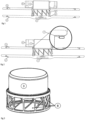
fig. 1 shows a cross-section through the rotor of a rotating packed bed apparatus containing the insert designed according to the invention, -
fig. 2 shows a cross-section through the rotor of a rotating packed bed apparatus containing the insert designed according to the invention and the seal,fig. 3 shows the cylindrical insert, -
fig. 3a shows the cylindrical insert with the lower part connected to the homolographic socket in the shape of a regular polygon in cross-section, -
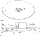
fig. 4 shows the cylindrical insert seated on the lower rotor plate, -
fig. 4a shows the cylindrical insert seated on the lower rotor plate with the lower part connected to the homolographic socket in the shape of a regular polygon in cross-section, -
fig. 5 shows the lower rotor plate, -
fig. 5a shows the lower rotor plate with the homolographic socket in the shape of a regular polygon in cross-section, -
fig. 6 shows a simplified diagram of the rotor of a rotating packed bed apparatus. - The solution designed according to the invention is illustrated in an implementation example not limiting the invention.
- The apparatus consists of a stationary housing and a rotating rotor. The rotating packed rotor consists of two rotor plates (2) and (5) and a cylindrical insert (3). This rotor has a shaft pivot socket (1) in its axis, on which the lower plate (2) of the rotor is placed. The lower plate (2) of the rotor has a homolographic socket (9) in which the cylindrical insert (3) is placed. The cylindrical insert (3) fits onto the inner diameter of the homolographic socket (9). The cylindrical insert (3) is pressed down by the top plate (5) of the rotor, which prevents it from sliding out of the cylindrical slot.
- In the solution designed according to the invention, gas and liquid flow, in the manner known from the state of the art, through the lower part of the cylindrical insert (3), which has holes (8). The upper part of the cylindrical insert (3) is placed in the seal (6), which prevents the gas from flowing past the packing (4).
- The liquid, as in a typical rotating packed bed (RPB) apparatus, is introduced internally, through additional liquid distributors; and the gas flow can be either co-current (gas entering the eye of the rotor) or counter-current (gas entering the outer housing) in relation to the liquid.
- On the wider outer part of the cylindrical insert (3), the packing (4) is wrapped or applied. The packing (4) and cylindrical insert (3) are covered from above by the top plate (5) of the rotor. The upper part of the cylindrical insert (3) is placed in the seal (6) located between the rotor and the device housing.
- The cylindrical insert (3) concentrically positions the packing (4) relative to the plates (2) and (5) the rotor and prevents gas from flowing past the packing (4). The cylindrical insert (3) provides vertical spacing between the lower plate (2) of the rotor and the upper plate (5) of the rotor. Concentric positioning is achieved by inserting the cylindrical insert (3) into a homolographic socket (9), preferably cylindrical or conical, located in the lower plate (2) of the rotor. The prevention of gas flow past the packing (4) is achieved by static placement between the surfaces of the cylindrical insert (3) cooperating with the upper plate of the rotor (5), and by placing the upper part of the cylindrical insert (3) in a dynamic seal (6), mounted to the housing of the device, ensuring a tight seal between the insert and the external housing of the device. The play between the gap of the cylindrical part of the socket (9) of the lower rotor plate (2) and the cylindrical insert (3) is less than 0.1% of the nominal fit dimension; whereby a seal (7) preferably of the O-ring type is placed between the upper plate (5) of the rotor and the cylindrical insert (3), and the upper part of the cylindrical insert (3) is placed in the seal (6). The gap between the lower plate (2) of the rotor and the cylindrical insert (3) is preferably smooth or profiled, whereby the shape of the wall with the gap between the lower plate of the rotor and the cylindrical insert is preferably cylindrical or conical.
- The apparatus consists of a stationary housing and a rotating rotor with a diagonal axis of rotation. The rotating packed rotor consists of two rotor plates (2) and (5) and a cylindrical insert (3). The lower rotor plate (2) is positioned at a 30° angle to the direction of the force of gravity. This rotor has a shaft pivot socket (1) in its axis, on which the lower plate (2) of the rotor is placed. The lower plate (2) of the rotor has a homolographic socket (9) in which the cylindrical insert (3) is placed. The cylindrical insert (3) fits onto the outer diameter of the homolographic socket (9). The cylindrical insert (3) is bolted to the rotor plates (2) and (5). In the solution designed according to the invention, gas and liquid flow, in the manner known from the state of the art, through the lower part of the cylindrical insert (3), which has holes (8). The upper part of the cylindrical insert (3) is placed in the seal (6), which prevents the gas from flowing past the packing (4).
- The liquid, as in a typical rotating packed bed (RPB) apparatus, is introduced internally, through additional liquid distributors; and the gas flow can be either co-current (gas entering the eye of the rotor) or counter-current (gas entering the outer housing) in relation to the liquid.
- On the wider outer part of the cylindrical insert (3), the packing (4) is wrapped or applied. The packing (4) and cylindrical insert (3) are covered from above by the top plate (5) of the rotor. The upper part of the cylindrical insert (3) is placed in the seal (6) located between the rotor and the device housing.
- The cylindrical insert (3) concentrically positions the packing (4) relative to the plates (2) and (5) the rotor and prevents gas from flowing past the packing (4). The cylindrical insert (3) provides vertical spacing between the lower plate (2) of the rotor and the upper plate (5) of the rotor. Concentric positioning is achieved by inserting the cylindrical insert (3) into a homolographic socket (9), preferably cylindrical or conical, located in the lower plate (2) of the rotor. The prevention of gas flow past the packing (4) is achieved with a static seal between the surfaces of the cylindrical insert (3) cooperating with the upper plate of the rotor (5), and by placing the upper part of the cylindrical insert (3) in a dynamic seal (6), mounted to the housing of the device, ensuring a tight seal between the insert and the external housing of the device. The play between the gap of the cylindrical part of the socket (9) of the lower rotor plate (2) and the cylindrical insert (3) is less than 0.1% of the nominal fit dimension. A seal (7) preferably of the O-ring type is placed between the top plate (5) of the rotor and the cylindrical insert (3), and the upper part of the cylindrical insert (3) is placed in the seal (6). The gap between the lower plate (2) of the rotor and the cylindrical insert (3) is preferably smooth or profiled, whereby the shape of the wall with the gap between the lower plate of the rotor and the cylindrical insert is preferably cylindrical or conical.
- The apparatus consists of a stationary housing and a rotating rotor with a diagonal vertical axis of rotation. The rotating packed rotor consists of two rotor plates (2) and (5) and a cylindrical insert (3). This rotor has a shaft pivot socket (1) in its axis, on which the lower plate (2) of the rotor is placed. The lower plate (2) of the rotor has a homolographic socket (9) in which the cylindrical insert (3) is placed. The cylindrical insert (3) fits onto the inner diameter of the homolographic socket (9) with a play of 0.05 mm. The cylindrical insert (3) is pressed by the top plate (5) of the rotor, which prevents it from sliding out of the homolographic socket (9), preferably cylindrical.
- On the wider, lower, outer part of the cylindrical insert (3), the packing (4) is wrapped or applied. The packing (4) and cylindrical insert (3) are covered from above by the top plate (5) of the rotor. The narrower upper part of the cylindrical insert (3) is placed in the seal (6) located between the rotor and the device housing.
- The cylindrical insert (3) concentrically positions the packing (4) relative to the plates (2) and (5) the rotor and prevents gas from flowing past the packing (4). The cylindrical insert (3) provides vertical spacing between the lower plate (2) of the rotor and the upper plate (5) of the rotor and, working in conjunction with the seals, prevents gas flow past the packing. The play between the lower rotor plate (2) and the cylindrical insert (3) is preferably within 0.05 - 0.1mm. The cylindrical insert (3) is stabilised by friction and pressure from above by the upper rotor plate (5). Concentric positioning involves placing the cylindrical insert (3) in a homolographic socket (9), preferably cylindrical, located in the lower plate (2) of the rotor.
- The lower part of the cylindrical insert (3) has quadrangular-shaped holes (8) and the upper part of the cylindrical insert (3) is placed in the seal (6). Between the top plate (5) of the rotor and the cylindrical insert (3) a seal (7) is inserted, preferably of the O-ring type, while the upper part of the cylindrical insert (3) is placed in the seal (6).
- The apparatus consists of a stationary housing and a rotating rotor with a vertical axis of rotation. The rotating packed rotor consists of two rotor plates (2) and (5) and a cylindrical insert (3). This rotor has a shaft pivot socket (1) in its axis, on which the lower plate (2) of the rotor is placed. The lower plate (2) of the rotor has a homolographic socket (9) in which the cylindrical insert (3) is placed. The cylindrical insert (3) fits onto the inner diameter of the homolographic socket (9) with a play of 0.05 mm. The cylindrical insert (3) is pressed by the top plate (5) of the rotor, which prevents it from sliding out of the homolographic socket (9), preferably cylindrical. The homolographic socket (9) has the shape of a regular polygon in cross-section.
- On the wider, lower, outer part of the cylindrical insert (3), the packing (4) is wrapped or applied. The packing (4) and cylindrical insert (3) are covered from above by the top plate (5) of the rotor. The narrower upper part of the cylindrical insert (3) is placed in the seal (6) located between the rotor and the device housing.
- The cylindrical insert (3) concentrically positions the packing (4) relative to the plates (2) and (5) the rotor and prevents gas from flowing past the packing (4). The cylindrical insert (3) provides vertical spacing between the lower plate (2) of the rotor and the upper plate (5) of the rotor and, working in conjunction with the seals, prevents gas flow past the packing. The play between the lower rotor plate (2) and the cylindrical insert (3) is preferably within 0.05 - 0.2mm. The cylindrical insert (3) is stabilised by friction and pressure from the upper rotor plate (5) and a detachable screw connection, known from the state of the art. Concentric positioning is achieved by inserting the cylindrical insert (3) into a homolographic socket (9) located in the lower plate (2) of the rotor. The lower part of the cylindrical insert (3) has quadrangular-shaped holes (8) and the upper part of the cylindrical insert (3) is placed in the seal (6). A seal (7) preferably of the O-ring type is placed between the top plate (5) of the rotor and the cylindrical insert (3), and the upper part of the cylindrical insert (3) is placed in the seal (6).
- The apparatus consists of a stationary housing and a rotating rotor with a diagonal axis of rotation. The lower rotor plate (2) is positioned at a 70° angle to the direction of the force of gravity. The rotor consists of two rotor plates (2) and (5) and a cylindrical insert (3). This rotor has a shaft pivot socket (1) in its axis, on which the lower plate (2) of the rotor is placed. The lower plate (2) of the rotor has a homolographic socket (9) in which the cylindrical insert (3) is placed. The cylindrical insert (3) fits onto the inner diameter of the homolographic socket (9) with a play of 0.05 mm. The cylindrical insert (3) is pressed down by the top plate (5) of the rotor, which prevents it from sliding out of the cylindrical socket (9). The homolographic socket (9) has the shape of a irregular polygon in cross-section.
- On the wider, lower, outer part of the cylindrical insert (3), the packing (4) is wrapped or applied. The packing (4) and cylindrical insert (3) are covered from above by the top plate (5) of the rotor. The narrower upper part of the cylindrical insert (3) is placed in the seal (6) located between the rotor and the device housing.
- The cylindrical insert (3) concentrically positions the packing (4) relative to the plates (2) and (5) the rotor and prevents gas from flowing past the packing (4). The cylindrical insert (3) provides vertical spacing between the lower plate (2) of the rotor and the upper plate (5) of the rotor and, working in conjunction with the seals, prevents gas flow past the packing. The play between the lower rotor plate (2) and the cylindrical insert (3) is preferably within 0.05 - 0.1mm. The cylindrical insert (3) is stabilised by friction and pressure from the upper rotor plate (5). Concentric positioning is achieved by inserting the cylindrical insert (3) into a homolographic socket (9) located in the lower plate (2) of the rotor. The lower part of the cylindrical insert (3) has quadrangular-shaped holes (8) and the upper part of the cylindrical insert (3) is placed in the seal (6). A seal (7) preferably of the O-ring type is placed between the top plate (5) of the rotor and the cylindrical insert (3), and the upper part of the cylindrical insert (3) is placed in the seal (6).
Claims (8)
- A cylindrical insert for the rotor for rotating packed bed apparatus in a cylindrical shape, characterised in that it is placed concentrically in a homolographic through-hole located in the upper plate (5) of the rotor and in a homolographic socket (9) in the lower plate (2) of the rotor; whereby the cylindrical insert (3) passes through the homolographic hole in the upper plate (5) of the rotor and positions the upper plate of the rotor (5) relative to the lower plate (2) of the rotor.
- The cylindrical insert for the rotor for rotating packed bed apparatus according to claim 1, characterised in that it is attached to the lower (2) and upper (5) rotor plates by way of temporary fastening known from the state of the art.
- The cylindrical insert for the rotor for rotating packed bed apparatus according to claim 1, characterised in that the cylindrical part of the insert (3) located in the upper (5) plate of the rotor, at the height of the seal (6) projects above the upper plate (5) of the rotor; while the lower part of the cylindrical insert (3) has holes (8) in the cylindrical part located between the rotor plates, through which liquid and gas flow in the manner known from the state of the art.
- The cylindrical insert for the rotor for rotating packed bed apparatus according to claim 1 and 3, characterised in that the connection between the lower plate (2) of the rotor and the cylindrical insert (3) has a play of not more than 0.5% of the nominal dimension of the fit, or a interference fit of not more than 0.5%; whereby the connection between the upper plate (5) of the rotor and the cylindrical insert (3) is sealed with a synthetic sealing material
- The cylindrical insert for the rotor for rotating packed bed apparatus according to claim 1 or 3 or 4, characterised in that the gap between the lower plate (2) of the rotor and the cylindrical insert (3) is preferably smooth, with the shape of the wall with the gap between the lower plate of the rotor (2) and the cylindrical insert (3) being preferably cylindrical or conical.
- The cylindrical insert for the rotor for rotating packed bed apparatus according to claim 1 or 3 or 4, characterised in that the gap between the upper plate (5) of the rotor and the cylindrical insert (3) is preferably smooth and the shape of the wall with the gap between the upper plate (5) of the rotor and the cylindrical insert (3) is preferably cylindrical or conical; whereby the connection between the upper plate (5) of the rotor and the cylindrical insert (3) is a connection sealed with synthetic material.
- The cylindrical insert for the rotor for rotating packed bed apparatus according to claim 1 or 3 or 4 or 5 or 6, characterised in that the gap between the lower plate (2) of the rotor and the cylindrical insert (3) is profiled, with the shape of the wall with the gap between the lower plate of the rotor (2) and the cylindrical insert (3) being preferably cylindrical or conical.
- The cylindrical insert for the rotor for rotating packed bed apparatus according to claim 1 or 3 or 4 or 5 or 6 or 7, characterised in that the lower part of the cylindrical insert (3) connected to the homolographic socket (9) has a cross-sectional shape being preferably circular, a regular polygon or irregular polygon.
Applications Claiming Priority (1)
| Application Number | Priority Date | Filing Date | Title |
|---|---|---|---|
| PL446855A PL446855A1 (en) | 2023-11-27 | 2023-11-27 | Cylindrical insert for rotor of rotating filling devices |
Publications (1)
| Publication Number | Publication Date |
|---|---|
| EP4559551A1 true EP4559551A1 (en) | 2025-05-28 |
Family
ID=93656169
Family Applications (1)
| Application Number | Title | Priority Date | Filing Date |
|---|---|---|---|
| EP24460034.2A Pending EP4559551A1 (en) | 2023-11-27 | 2024-11-07 | Cylindrical insert for the rotor for rotating packed bed apparatus |
Country Status (2)
| Country | Link |
|---|---|
| EP (1) | EP4559551A1 (en) |
| PL (1) | PL446855A1 (en) |
Citations (5)
| Publication number | Priority date | Publication date | Assignee | Title |
|---|---|---|---|---|
| CN101229503B (en) * | 2007-10-23 | 2010-08-25 | 浙江工业大学 | Baffled gas-liquid cross-flow type supergravity field rotating bed device |
| CN102247706B (en) * | 2011-05-19 | 2013-10-16 | 北京化工大学 | Rotating packed bed device with function of regulating and controlling axial liquid distribution |
| US20130319235A1 (en) | 2011-02-09 | 2013-12-05 | Alstom Technology Ltd | Rotating packed bed |
| CN103239885B (en) * | 2013-04-27 | 2015-04-22 | 浙江工业大学 | Supergravity rotating packed bed device with middle feeding function and built-in liquid collection redistributor |
| WO2015101826A1 (en) | 2013-12-31 | 2015-07-09 | Hindustan Petroleum Corporation Ltd. | Rotating packed bed unit |
Family Cites Families (1)
| Publication number | Priority date | Publication date | Assignee | Title |
|---|---|---|---|---|
| CN102580462B (en) * | 2011-01-12 | 2014-11-05 | 北京化工大学 | Novel method for capturing and separating carbon dioxide |
-
2023
- 2023-11-27 PL PL446855A patent/PL446855A1/en unknown
-
2024
- 2024-11-07 EP EP24460034.2A patent/EP4559551A1/en active Pending
Patent Citations (5)
| Publication number | Priority date | Publication date | Assignee | Title |
|---|---|---|---|---|
| CN101229503B (en) * | 2007-10-23 | 2010-08-25 | 浙江工业大学 | Baffled gas-liquid cross-flow type supergravity field rotating bed device |
| US20130319235A1 (en) | 2011-02-09 | 2013-12-05 | Alstom Technology Ltd | Rotating packed bed |
| CN102247706B (en) * | 2011-05-19 | 2013-10-16 | 北京化工大学 | Rotating packed bed device with function of regulating and controlling axial liquid distribution |
| CN103239885B (en) * | 2013-04-27 | 2015-04-22 | 浙江工业大学 | Supergravity rotating packed bed device with middle feeding function and built-in liquid collection redistributor |
| WO2015101826A1 (en) | 2013-12-31 | 2015-07-09 | Hindustan Petroleum Corporation Ltd. | Rotating packed bed unit |
Also Published As
| Publication number | Publication date |
|---|---|
| PL446855A1 (en) | 2025-06-02 |
Similar Documents
| Publication | Publication Date | Title |
|---|---|---|
| US8523187B2 (en) | Axial face seal assembly, mounting method and mounting fixture | |
| US7029584B2 (en) | Rotating filter | |
| US8834101B2 (en) | Mechanical seal for large pumps | |
| US4270760A (en) | Sealing assembly | |
| EP3023160B1 (en) | A centrifugal separator | |
| US10563541B2 (en) | Securing device, steam turbine, and rotary machine manufacturing method and assembly method | |
| US7213660B2 (en) | Washpipe seal | |
| EP4559551A1 (en) | Cylindrical insert for the rotor for rotating packed bed apparatus | |
| RU2645896C9 (en) | Safety head | |
| US7806411B2 (en) | Radial seal assembly | |
| US6602412B2 (en) | Single cartridge filter housing | |
| US4575100A (en) | Seal assembly which is hydraulically actuated | |
| US11260327B2 (en) | Filter element having intermittent coupling with housing cover | |
| CN106823699A (en) | Dehydrating cartridge is fixed on the device at the casing section of compressed air preparation instrument | |
| GB2506148A (en) | Flange assembly | |
| JP5154996B2 (en) | Scraper equipment | |
| KR850001113A (en) | High pressure feeder | |
| JP2024512699A (en) | Filter systems, filter mounting mechanisms, and filter elements used in and with filter systems and filter mounting mechanisms. | |
| US20170002955A1 (en) | Rotary Valve Seal Pressure and Indicator System | |
| US6336746B1 (en) | Structure for supporting rotary shaft | |
| CN219307992U (en) | Automatic main shaft deviation rectifying device of centrifugal extractor | |
| RU2270325C1 (en) | Well head sealing device | |
| JP2021060038A (en) | Pitot tube stabilizing arrangements | |
| GB2576609A (en) | Filter device and method for mounting such a filter device | |
| EP0222933A1 (en) | Mixing apparatus having a mixing screw and a conical mixing vessel |
Legal Events
| Date | Code | Title | Description |
|---|---|---|---|
| PUAI | Public reference made under article 153(3) epc to a published international application that has entered the european phase |
Free format text: ORIGINAL CODE: 0009012 |
|
| STAA | Information on the status of an ep patent application or granted ep patent |
Free format text: STATUS: THE APPLICATION HAS BEEN PUBLISHED |
|
| AK | Designated contracting states |
Kind code of ref document: A1 Designated state(s): AL AT BE BG CH CY CZ DE DK EE ES FI FR GB GR HR HU IE IS IT LI LT LU LV MC ME MK MT NL NO PL PT RO RS SE SI SK SM TR |
|
| STAA | Information on the status of an ep patent application or granted ep patent |
Free format text: STATUS: REQUEST FOR EXAMINATION WAS MADE |
|
| 17P | Request for examination filed |
Effective date: 20250908 |
|
| STAA | Information on the status of an ep patent application or granted ep patent |
Free format text: STATUS: EXAMINATION IS IN PROGRESS |
|
| 17Q | First examination report despatched |
Effective date: 20251024 |
|
| GRAP | Despatch of communication of intention to grant a patent |
Free format text: ORIGINAL CODE: EPIDOSNIGR1 |
|
| STAA | Information on the status of an ep patent application or granted ep patent |
Free format text: STATUS: GRANT OF PATENT IS INTENDED |