EP4559404A2 - Acoustic matching member and method for capturing medical image - Google Patents
Acoustic matching member and method for capturing medical image Download PDFInfo
- Publication number
- EP4559404A2 EP4559404A2 EP24211269.6A EP24211269A EP4559404A2 EP 4559404 A2 EP4559404 A2 EP 4559404A2 EP 24211269 A EP24211269 A EP 24211269A EP 4559404 A2 EP4559404 A2 EP 4559404A2
- Authority
- EP
- European Patent Office
- Prior art keywords
- acoustic matching
- compression
- capturing
- matching member
- hydrophilic
- Prior art date
- Legal status (The legal status is an assumption and is not a legal conclusion. Google has not performed a legal analysis and makes no representation as to the accuracy of the status listed.)
- Pending
Links
Images


Classifications
-
- A—HUMAN NECESSITIES
- A61—MEDICAL OR VETERINARY SCIENCE; HYGIENE
- A61B—DIAGNOSIS; SURGERY; IDENTIFICATION
- A61B6/00—Apparatus or devices for radiation diagnosis; Apparatus or devices for radiation diagnosis combined with radiation therapy equipment
- A61B6/50—Apparatus or devices for radiation diagnosis; Apparatus or devices for radiation diagnosis combined with radiation therapy equipment specially adapted for specific body parts; specially adapted for specific clinical applications
- A61B6/502—Apparatus or devices for radiation diagnosis; Apparatus or devices for radiation diagnosis combined with radiation therapy equipment specially adapted for specific body parts; specially adapted for specific clinical applications for diagnosis of breast, i.e. mammography
-
- A—HUMAN NECESSITIES
- A61—MEDICAL OR VETERINARY SCIENCE; HYGIENE
- A61B—DIAGNOSIS; SURGERY; IDENTIFICATION
- A61B6/00—Apparatus or devices for radiation diagnosis; Apparatus or devices for radiation diagnosis combined with radiation therapy equipment
- A61B6/04—Positioning of patients; Tiltable beds or the like
- A61B6/0407—Supports, e.g. tables or beds, for the body or parts of the body
- A61B6/0414—Supports, e.g. tables or beds, for the body or parts of the body with compression means
-
- A—HUMAN NECESSITIES
- A61—MEDICAL OR VETERINARY SCIENCE; HYGIENE
- A61B—DIAGNOSIS; SURGERY; IDENTIFICATION
- A61B6/00—Apparatus or devices for radiation diagnosis; Apparatus or devices for radiation diagnosis combined with radiation therapy equipment
- A61B6/44—Constructional features of apparatus for radiation diagnosis
- A61B6/4417—Constructional features of apparatus for radiation diagnosis related to combined acquisition of different diagnostic modalities
-
- A—HUMAN NECESSITIES
- A61—MEDICAL OR VETERINARY SCIENCE; HYGIENE
- A61B—DIAGNOSIS; SURGERY; IDENTIFICATION
- A61B8/00—Diagnosis using ultrasonic, sonic or infrasonic waves
- A61B8/40—Positioning of patients, e.g. means for holding or immobilising parts of the patient's body
- A61B8/403—Positioning of patients, e.g. means for holding or immobilising parts of the patient's body using compression means
-
- A—HUMAN NECESSITIES
- A61—MEDICAL OR VETERINARY SCIENCE; HYGIENE
- A61B—DIAGNOSIS; SURGERY; IDENTIFICATION
- A61B8/00—Diagnosis using ultrasonic, sonic or infrasonic waves
- A61B8/42—Details of probe positioning or probe attachment to the patient
- A61B8/4272—Details of probe positioning or probe attachment to the patient involving the acoustic interface between the transducer and the tissue
-
- A—HUMAN NECESSITIES
- A61—MEDICAL OR VETERINARY SCIENCE; HYGIENE
- A61B—DIAGNOSIS; SURGERY; IDENTIFICATION
- A61B8/00—Diagnosis using ultrasonic, sonic or infrasonic waves
- A61B8/44—Constructional features of the ultrasonic, sonic or infrasonic diagnostic device
- A61B8/4416—Constructional features of the ultrasonic, sonic or infrasonic diagnostic device related to combined acquisition of different diagnostic modalities, e.g. combination of ultrasound and X-ray acquisitions
-
- A—HUMAN NECESSITIES
- A61—MEDICAL OR VETERINARY SCIENCE; HYGIENE
- A61K—PREPARATIONS FOR MEDICAL, DENTAL OR TOILETRY PURPOSES
- A61K49/00—Preparations for testing in vivo
- A61K49/22—Echographic preparations; Ultrasonic imaging preparations
- A61K49/222—Echographic preparations; Ultrasonic imaging preparations characterised by a special physical form, e.g. emulsions, liposomes
- A61K49/226—Solutes, emulsions, suspensions, dispersions, semi-solid forms, e.g. hydrogels
-
- A—HUMAN NECESSITIES
- A61—MEDICAL OR VETERINARY SCIENCE; HYGIENE
- A61B—DIAGNOSIS; SURGERY; IDENTIFICATION
- A61B6/00—Apparatus or devices for radiation diagnosis; Apparatus or devices for radiation diagnosis combined with radiation therapy equipment
- A61B6/44—Constructional features of apparatus for radiation diagnosis
- A61B6/4405—Constructional features of apparatus for radiation diagnosis the apparatus being movable or portable, e.g. handheld or mounted on a trolley
-
- A—HUMAN NECESSITIES
- A61—MEDICAL OR VETERINARY SCIENCE; HYGIENE
- A61B—DIAGNOSIS; SURGERY; IDENTIFICATION
- A61B8/00—Diagnosis using ultrasonic, sonic or infrasonic waves
- A61B8/08—Clinical applications
- A61B8/0825—Clinical applications for diagnosis of the breast, e.g. mammography
-
- A—HUMAN NECESSITIES
- A61—MEDICAL OR VETERINARY SCIENCE; HYGIENE
- A61B—DIAGNOSIS; SURGERY; IDENTIFICATION
- A61B8/00—Diagnosis using ultrasonic, sonic or infrasonic waves
- A61B8/42—Details of probe positioning or probe attachment to the patient
- A61B8/4272—Details of probe positioning or probe attachment to the patient involving the acoustic interface between the transducer and the tissue
- A61B8/4281—Details of probe positioning or probe attachment to the patient involving the acoustic interface between the transducer and the tissue characterised by sound-transmitting media or devices for coupling the transducer to the tissue
Definitions
- the present disclosure relates to an acoustic matching member and a method for capturing a medical image.
- An ultrasound image capturing apparatus that captures an ultrasound image of a subject is known.
- a method of capturing an ultrasound image using an ultrasound image capturing apparatus for example, there is known an image capturing method of capturing an ultrasound image in a state where a subject is compressed by a compression member.
- JP2009-82399A discloses an image capturing method of capturing an ultrasound image of a breast in a compressed state using a mammography apparatus that captures a radiographic image with the breast in a compressed state by a compression member as a subject.
- the body surface in a state where the acoustic matching member is applied is scanned with an ultrasound probe. It is desirable that the acoustic matching member spreads on the body surface and remains on the body surface.
- a gel-like acoustic matching member such as echo jelly used in the related art may be difficult to wipe off.
- the present disclosure has been made in consideration of the above circumstances, and an object of the present disclosure is to provide an acoustic matching member that spreads and remains on a body surface and is easily wiped off, and a method for capturing a medical image.
- an acoustic matching member is an acoustic matching member that is applied to a body surface in a case where an ultrasound image is captured, in which the acoustic matching member is a mixed solution containing water and a hydrophilic polymer having a hydrophilic functional group and having 8 or more carbon atoms and a viscosity of the acoustic matching member is 5 mPa ⁇ s or more and 20000 mPa ⁇ s or less.
- the hydrophilic polymer is a monovalent alcohol and an aliphatic alcohol.
- the hydrophilic polymer is at least one of sethanol, stearyl alcohol, behenyl alcohol, or lauryl alcohol.
- the mixed solution is cosmetic water.
- the ultrasound image is captured by performing scanning on a compression member that puts a subject in a compressed state with a probe.
- a method for capturing a medical image comprises, in a state where a subject is in a state of being compressed by a compression member having a compression surface of which a region in contact with a body surface of the subject is subjected to hydrophilic processing, the subject being in a state where the body surface is coated with an acoustic matching member that is a mixed solution containing water and a hydrophilic polymer having a hydrophilic functional group and having 8 or more carbon atoms, and that has a viscosity of 5 mPa ⁇ s or more and 20000 mPa ⁇ s or less, performing ultrasound image capturing of acquiring an ultrasound image obtained by scanning a surface of the compression member opposite to the compression surface with a probe.
- the subject in the state of being compressed by the compression member is irradiated with a radiation, and a radiographic image capturing is performed to acquire a radiographic image obtained by a radiation detector detecting the radiation transmitted through the subject.
- the hydrophilic processing is processing of performing hydrophilic coating on the region.
- the hydrophilic processing is processing of providing unevenness in the region.
- the processing of providing the unevenness is processing of providing a plurality of grooves having a depth of 30 ⁇ m or more and a groove width of 20 ⁇ m or more and 30 ⁇ m or less, with a surface width of 10 ⁇ m or more and 30 ⁇ m or less.
- the acoustic matching member can spread and remain on a body surface, and can be easily wiped off.
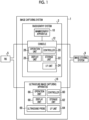
- FIG. 1 is a configuration diagram showing an example of the overall configuration of an image capturing system 1 according to the present embodiment.
- an image capturing system 1 comprises a radiography system 2 and an ultrasound image capturing apparatus 16.
- the ultrasound image capturing apparatus 16 is an apparatus that captures an ultrasound image with a breast of an examinee as a subject by a user, and is a so-called cart-type ultrasound image capturing apparatus.
- the ultrasound image capturing apparatus 16 may be an ultrasound image capturing apparatus of a so-called compact type or a handheld type other than the cart type.
- the ultrasound image capturing apparatus 16 comprises a controller 60, a storage unit 62, an interface (I/F) unit 64, an ultrasound probe 69, an operation unit 66, and a display unit 68.
- the controller 60 comprises a central processing unit (CPU), a read only memory (ROM), a random access memory (RAM), and the like (none of which are shown), and controls the operation of the entire ultrasound image capturing apparatus 16.
- the ROM stores, in advance, various programs, including a program for performing control related to ultrasound image capturing, which is executed by the CPU.
- the RAM transitorily stores various types of data.
- captured ultrasound images and various other types of information are stored in the storage unit 62.
- a hard disk drive (HDD), a solid state drive (SSD), or the like is exemplified.
- the operation unit 66 is used by the user to input, for example, commands or various kinds of information related to the capture of an ultrasound image.
- the operation unit 66 is not particularly limited. Examples of the operation unit 66 include various switches, a touch panel, a touch pen, and a mouse.
- the display unit 68 displays, for example, various types of information or an ultrasound image corresponding to the reception signal received from the ultrasound probe 69. Note that, the operation unit 66 and the display unit 68 may be integrated into a touch panel display.
- the I/F unit 64 communicates various types of information with the RIS 5 and the image storage system 9 through wireless communication or wired communication.
- the ultrasound image captured by the ultrasound image capturing apparatus 16 is transmitted to the image storage system 9 through the I/F unit 64 through wireless communication or wired communication.
- the ultrasound probe 69 is moved along an upper surface 70A (see Fig. 2 , a surface opposite to the surface that comes into contact with the breast of the examinee) of the compression member 70 by the user and scans the breast with ultrasound to acquire an ultrasound image of the breast.
- the ultrasound probe 69 comprises a plurality of ultrasound transducers (not shown) that are one-dimensionally or two-dimensionally arranged. Each of the ultrasound transducers transmits the ultrasound based on the applied drive signal, receives ultrasound echoes, and outputs a reception signal.
- each of the plurality of ultrasound transducers is a transducer configured by forming electrodes at both ends of a piezoelectric material (piezoelectric body), such as a piezoelectric ceramic typified by lead (Pb) zirconate titanate (PZT) or a polymeric piezoelectric element typified by polyvinylidene difluoride (PVDF).
- piezoelectric body such as a piezoelectric ceramic typified by lead (Pb) zirconate titanate (PZT) or a polymeric piezoelectric element typified by polyvinylidene difluoride (PVDF).
- Pb lead
- PVDF polyvinylidene difluoride
- Pulsed or continuous wave ultrasound is generated from each transducer by the expansion and contraction and the ultrasound is synthesized to form an ultrasound beam.
- each transducer receives the propagated ultrasound and is then expanded and contracted to generate an electric signal.
- the electric signal is output as an ultrasound reception signal and is input
- the radiography system 2 includes a mammography apparatus 10 and a console 12.
- the console 12 has a function of controlling the mammography apparatus 10 using, for example, an imaging order and various kinds of information acquired from a radiology information system (RIS) 5 through a wireless communication local area network (LAN) and commands input by the user through an operation unit 66 (see Fig. 2 ) of the mammography apparatus 10.
- RIS radiology information system
- LAN wireless communication local area network
- Examples of the console 12 include a server computer.
- the console 12 comprises a controller 20, a storage unit 22, an I/F unit 24, an operation unit 26, and a display unit 28.
- the controller 20 comprises a CPU, a ROM, a RAM, and the like (not shown), and controls the operation of the mammography apparatus 10.
- the ROM stores, in advance, various programs including a program for controlling the mammography apparatus 10 executed by the CPU.
- the RAM transitorily stores various types of data.
- the storage unit 22 stores the captured radiographic image, various other information, and the like. Specific examples of the storage unit 22 include an HDD, an SSD, and the like.
- the operation unit 26 is used for a user to input commands or various kinds of information related to the capturing of the radiographic image.
- the operation unit 26 is not particularly limited, and examples of the operation unit 26 include various switches, a touch panel, a touch pen, a mouse, and the like.
- the display unit 28 displays various kinds of information, a radiographic image captured by the mammography apparatus 10, and the like.
- the operation unit 26 and the display unit 28 may be integrated into a touch panel display.
- the I/F unit 24 performs communication of various kinds of information to and from the image storage system 9, such as the RIS 5 and a picture archiving and communication systems (PACS), by wireless communication or wired communication.
- the radiographic image captured by the mammography apparatus 10 is transmitted to the image storage system 9 by wireless communication or wired communication through the I/F unit 24.
- the mammography apparatus 10 irradiates the breast of an examinee as a subject with radiation R (for example, X-rays) to capture a radiographic image of the breast.
- R for example, X-rays
- the mammography apparatus 10 may be an apparatus that images the breast of the examinee in a state where the examinee is sitting on a chair (including a wheelchair) or the like (sitting state) in addition to a state where the examinee is standing (standing state).
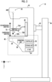
- Fig. 2 is a side view showing an example of the appearance of the mammography apparatus 10 of the present embodiment.
- Fig. 2 is a side view showing the mammography apparatus 10 as viewed from the right side of an examinee.
- the mammography apparatus 10 comprises a radiation source 36R, a radiation detector 30, an imaging table 40 disposed between the radiation source 36R and the radiation detector 30, and a compression member 70 that compresses the breast between the compression member 70 and the imaging table 40.
- the imaging table 40 comprises a controller 50, a storage unit 52, an I/F unit 54, an operation unit 56, and the radiation detector 30.
- the controller 50 controls an overall operation of the mammography apparatus 10 in accordance with the control of the console 12.
- the controller 50 comprises a CPU, a ROM, a RAM, and the like (not shown).
- the ROM stores, in advance, various programs, including a program for performing control related to radiographic image capturing, which is executed by the CPU.
- the RAM transitorily stores various types of data.
- Image data of a radiographic image and various other types of information are stored in the storage unit 52.
- the storage unit 52 is realized by, for example, a storage medium such as an HDD, an SSD, and a flash memory.
- image data of a radiographic image is simply referred to as a "radiographic image”.
- image data of an ultrasound image is simply referred to as an “ultrasound image”.
- the I/F unit 54 communicates various types of information with the console 12 by wired communication or wireless communication. Specifically, the I/F unit 54 receives information regarding the control of the mammography apparatus 10 from the console 12. In addition, the I/F unit 54 transmits a radiographic image to the console 12.
- the operation unit 56 is a part provided on the imaging table 40 or the like and operable by a user with a hand, a foot, or the like, and is, for example, a switch, a button, a touch panel, or the like.
- the operation unit 56 may receive a voice input from the user.
- the radiation detector 30 is disposed inside the imaging table 40 and detects the radiation R transmitted through the breast which is the subject.
- the breast of the examinee in a case where imaging is performed, the breast of the examinee is positioned on an imaging surface 40A of the imaging table 40 by a user such as a doctor or a radiology technician.
- the imaging surface 40A and the like with which the breast of the examinee comes into contact are made of carbon or the like in terms of the transmittance and intensity of the radiation R.
- the radiation detector 30 detects the radiation R transmitted through the breast of the examinee and the imaging table 40, generates a radiographic image based on the detected radiation R, and outputs the generated radiographic image.
- the type of the radiation detector 30 of the present embodiment is not particularly limited.
- the radiation detector 30 may be an indirect conversion type radiation detector that converts the radiation R into light and converts the converted light into electric charges, or may be a direct conversion type radiation detector that directly converts the radiation R into electric charges.
- the radiation source 36R is provided in a radiation emitting unit 36.
- the radiation emitting unit 36 is provided on the arm portion 42 together with the imaging table 40 and a compression unit 46.
- the mammography apparatus 10 of the present embodiment comprises the arm portion 42, a base 44, and a shaft portion 45.
- the arm portion 42 is held by the base 44 so as to be movable in an up-down direction (Z-axis direction).
- the shaft portion 45 connects the arm portion 42 to the base 44. Further, the arm portion 42 can be relatively rotated with respect to the base 44, using the shaft portion 45 as a rotation axis.
- the compression member 70 is attached to the compression unit 46.
- the compression unit 46 and the arm portion 42 can be relatively rotated with respect to the base 44 separately, using the shaft portion 45 as a rotation axis.
- gears (not shown) are provided in each of the shaft portion 45, the arm portion 42, and the compression unit 46. Each gear is switched between an engaged state and a disengaged state to connect each of the arm portion 42 and the compression unit 46 to the shaft portion 45.
- One or both of the arm portion 42 and the compression unit 46 connected to the shaft portion 45 are rotated integrally with the shaft portion 45.
- the compression member 70 of the present embodiment is moved in the up-down direction (Z-axis direction) by a compression plate driving unit (not shown) provided in the compression unit 46, and compresses the breast of the examinee between the imaging table 40.
- a compression plate driving unit not shown
- the direction in which the breast is compressed in other words, the direction in which the compression member 70 approaches the imaging surface 40Ais referred to as a "compression direction”
- the direction in which the compression of the breast is released in other words, the direction in which the compression member 70 approaches the radiation emitting unit 36 is referred to as a "decompression direction”.
- the compression member 70 is not limited to a member that compresses the entire breast, but may be a member that compresses a part of the breast. In other words, the compression member 70 may be smaller than the breast.
- a compression member 70 for example, a compression member 70 used for so-called spot imaging, in which a radiographic image is captured of only a region where a lesion is present, is known.
- the compression member 70 is optically transparent in order to check positioning or a compressed state in the compression of the breast.
- the compression member 70 is made of a material having high transmittance for the radiation R.
- the compression member 70 is made of a material that facilitates the propagation of ultrasonic waves transmitted from the ultrasound probe 69 of the ultrasound image capturing apparatus 16. Examples of the material forming the compression member 70 include resins such as polymethylpentene, polycarbonate, acrylic, or polyethylene terephthalate.
- polymethylpentene is suitable as the material forming the compression member 70 since it has low rigidity, high elasticity, and high flexibility and has suitable values for acoustic impedance that affects the reflectivity of ultrasound waves and an attenuation coefficient that affects the attenuation of ultrasound waves.
- the member constituting the compression member 70 is not limited to the present embodiment.
- a hydrophilic region 70h which is subjected to hydrophilic processing on a region in contact with the breast W, is provided in a compression surface 70B of the compression member 70, which is a surface that comes into contact with the breast W of the examinee.
- the hydrophilic region 70h on the compression surface 70B may include at least a region in contact with the breast W, or may be the entire compression surface 70B.
- the breast W placed on the imaging surface 40A of the imaging table 40 is compressed by the compression member 70 in a state where the acoustic matching member 80 is applied to the body surface that comes into contact with the compression member 70.
- the acoustic matching member 80 is used to suppress a difference in acoustic impedance at a boundary surface between the breast W and the compression member 70.
- the acoustic matching member 80 needs to spread and remain on the body surface of the breast and the compression surface 70B.
- the viscosity of the acoustic matching member 80 is low, the contact angle with the body surface is large, and the acoustic matching member 80 does not spread over the entire body surface and remains as a plurality of water droplets.
- the viscosity of pure water is about 1 mPa ⁇ s, which is measured under the measurement conditions of a measurement temperature of 20°C and a rotation speed of 1300 rotations/minute (rpm)
- the acoustic matching member do not spread over the entire surface of the body and remain as a plurality of water droplets.
- the viscosity is low, the liquid is likely to flow, and thus the acoustic matching member is unlikely to remain on the surface of the body.
- the acoustic matching member such as echo jelly that is generally used in capturing of an ultrasound image
- the viscosity is 25000 mPa ⁇ s to 45000 mPa ⁇ s
- the acoustic matching member can sufficiently spread and remain on the entire body surface.
- the viscosity is high in this way, the acoustic matching member is difficult to flow, and thus it is difficult to wipe off the acoustic matching member, and the acoustic matching member is difficult to be cleaned.
- the viscosity measured under the measurement conditions of a measurement temperature of 20°C and a rotation speed of 1300 rotations/minute (rpm) by a rotational viscometer such as a B-type viscometer is 5 mPa s or more and 20000 mPa s or less.
- the acoustic matching member 80 of the present embodiment that can suppress a difference in acoustic impedance at a boundary surface between the breast W and the compression member 70 and that has the above-described viscosity is a mixed solution containing water and a hydrophilic polymer having a hydrophilic functional group and having 8 or more carbon atoms.
- a hydrophilic polymer a monovalent alcohol and an aliphatic alcohol are preferable.
- hydrophilic polymer at least one of sethanol (CH 3 (CH 2 ) 15 OH), stearyl alcohol (CH 3 (CH 2 ) 17 OH), behenyl alcohol (CH 3 (CH 2 ) 21 OH), or lauryl alcohol (CH 3 (CH 2 ) 11 OH) is preferable.
- cosmetic water can be used as the mixed solution used as the acoustic matching member 80. It is preferable that the cosmetic water does not contain anhydrous ethanol referred to as “alcohol-free” or “non-alcohol”.
- the acoustic matching member 80 is sufficiently spread on the compression surface 70B of the compression member 70 and air bubbles or the like are not mixed. Therefore, in the compression surface 70B of the compression member 70, it is preferable that at least a region in contact with the breast W is hydrophilic. In other words, it is preferable that the contact angle of the acoustic matching member 80 with respect to at least the region in contact with the breast W of the compression surface 70B is small.
- the above-described resins and the like that can be used as a material for the compression member 70 are often hydrophobic. Therefore, as shown in Fig. 3 , the compression surface 70B of the compression member 70 according to the present embodiment has a hydrophilic region 70h that is subjected to hydrophilic processing in a region in contact with the breast W.
- the hydrophilic region 70h of the compression surface 70B of the compression member 70 according to the present embodiment is coated with a hydrophilic coating.
- the type of the hydrophilic coating and the method of performing the hydrophilic coating are not limited.
- Examples of the method of performing the hydrophilic coating include a method of performing a plasma treatment of forming a functional group (OH group) having a high hydrophilicity on a surface of the hydrophilic region 70h using plasma and activating and planarizing the surface to chemically improve the hydrophilicity.
- a plasma treatment of forming a functional group (OH group) having a high hydrophilicity on a surface of the hydrophilic region 70h using plasma and activating and planarizing the surface to chemically improve the hydrophilicity.
- examples of the method of performing the hydrophilic coating include a method of improving the hydrophilicity by coating a surfactant on the hydrophilic region 70h to reduce the interfacial tension at the interface between the acoustic matching member 80 and the compression surface 70B.
- examples of the method of performing the hydrophilic coating include a method of improving the hydrophilicity by coating a hydrophilic binder on the hydrophilic region 70h to improve the adhesiveness between the acoustic matching member 80 and the compression surface 70B.
- the capturing of the radiographic image and the capturing of the ultrasound image are continuously performed in a state where the breast W is put in a compressed state by the compression member 70.
- the capturing of the radiographic image and the capturing of the ultrasound image are continuously performed without completely releasing the compression by the compression member 70, the capturing of the radiographic image is performed in a state where the acoustic matching member 80 is provided. Therefore, the above described the hydrophilic processing performed on the hydrophilic region 70h of the compression surface 70B of the compression member 70, and the material of the acoustic matching member 80 are specifically selected in consideration of the influence on the radiographic image.
- the hydrophilic polymer is composed of atoms having an atomic number of 11 or less as the acoustic matching member 80.
- FIG. 4 is a flowchart showing an example of a flow of capturing the radiographic image and the ultrasound image using the image capturing system 1 according to the present embodiment.
- Step S10 of Fig. 9 the user positions the breast W of the examinee, which is the subject, on the imaging surface 40A of the imaging table 40.
- Step S12 as shown in Fig. 3 , the user applies the acoustic matching member 80 to the body surface of the breast W.
- the user gives a command to compress the breast W by the operation unit 66.
- Step S14 the controller 60 of the mammography apparatus 10 starts compressing the breast W by the compression member 70. Specifically, in a case where a command to compress the breast W is received, the controller 60 moves the compression member 70 in the compression direction, and puts the breast W into a compressed state between the compression member 70 and the imaging surface 40A of the imaging table 40. Accordingly, the breast W is in contact with the hydrophilic region 70h of the compression surface 70B of the compression member 70 via the acoustic matching member 80.
- the mammography apparatus 10 captures the radiographic image of the breast W. Specifically, the user operates an irradiation switch included in the operation unit 66 to irradiate the breast W with the radiation R emitted from the radiation source 36R and to capture the radiographic image with the radiation detector 30.
- the radiographic image captured by the mammography apparatus 10 is output to the console 12, is output from the console 12 to the image storage system 9 at a predetermined timing, and is stored in the image storage system 9.
- Step S 18 the user disposes the acoustic matching member 82 on the upper surface 70A of the compression member 70.
- the acoustic matching member 82 is used to suppress a difference in acoustic impedance at a boundary surface between the compression member 70 and the ultrasound probe 69.
- a general-purpose echo jelly, a gel pad, or the like is used. It should be noted that, unlike the aspect shown in Fig. 3 , in a case where the acoustic matching member 82 is provided on the surface of the ultrasound probe 69 that comes into contact with the compression member 70, this step is omitted.
- Step S20 the technician scans the breast W compressed by the compression member 70 with the ultrasound probe 69 of the ultrasound image capturing apparatus 16 along the upper surface 70A of the compression member 70 on which the acoustic matching member 82 is provided to capture a plurality of ultrasound images.
- the ultrasound image captured by the ultrasound image capturing apparatus 16 is temporarily stored in the storage unit 62, is then output from the ultrasound image capturing apparatus 16 to the image storage system 9 at a predetermined timing, and is stored in the image storage system 9.
- Step S22 the processing of Step S22 is completed, the capturing of the radiographic image and the ultrasound image is completed.
- the acoustic matching member 80 applied to the body surface of the breast W is wiped off by the examinee.
- the acoustic matching member 80 adhering to the compression surface 70B of the compression member 70 and the acoustic matching member 82 adhering to the upper surface 70A are cleaned.
- Fig. 5 shows a part of the compression member 70.
- the wettability that is, the hydrophilicity is determined based on the surface area of the interface between the solid and the liquid, and the hydrophilicity may be increased by forming an uneven structure on the hydrophilic interface to increase the surface area.
- a plurality of grooves are provided as the hydrophilic processing to provide unevenness in the hydrophilic region 70h.
- the contact angle decreases.
- the groove width H1 and the surface width H2 increase, the surface approaches flatness. Therefore, in consideration of the affinity with the acoustic matching member 80, in a case where the grooves are provided as the uneven structure as in the present modification example, it is preferable that the plurality of grooves in which the groove depth D is 30 ⁇ m or more and the groove width H1 is 20 ⁇ m or more and 30 ⁇ m or less are provided at the surface width H2 of 10 ⁇ m or more and 30 ⁇ m or less.
- processing of providing such an uneven structure examples include so-called emboss processing.
- a specific processing method is not limited. For example, a method of directly forming the hydrophilic region 70h of the compression surface 70B of the compression member 70 in an uneven shape may be used. In addition, for example, a method of applying a hydrophilic coating agent or the like to the hydrophilic region 70h to impart an uneven shape to the surface may be used.
- the transparency of the compression member 70 may be reduced by performing the unevenness processing on the hydrophilic region 70h of the compression surface 70B of the compression member 70.
- the acoustic matching member 80 is in a state of being filled in the groove portion having the uneven structure, and the transparency can be improved.
- the transparency can be improved, and thus the user can sufficiently visually recognize the state of the breast W through the compression member 70.
- the acoustic matching member 80 of the above-described embodiment is an acoustic matching member that is applied to a body surface in a case where an ultrasound image is captured, and is a mixed solution containing water and a hydrophilic polymer having a hydrophilic functional group and having 8 or more carbon atoms, and that has the viscosity 5 mPa ⁇ s or more and 20000 mPa ⁇ s or less.
- the viscosity can be set to an appropriate viscosity, and thus, the acoustic matching member 80 can spread and remain on the body surface, and can be easily wiped off.
- the cosmetic water is used as the acoustic matching member, it is possible to protect the body surface, for example, to give moisture to the breast which is the subject.
- continuously capturing the radiographic image and the ultrasound image while the breast W is in a compressed state by the compression member 70 may be referred to as "continuous imaging".
- the order of capturing the radiographic image (Step S16 in Fig. 4 ) and capturing the ultrasound image (Step S20 in Fig. 4 ) is not limited. However, from the viewpoint of reducing the compression time of the breast W, it is preferable to perform the capturing of the radiographic image first as in the present embodiment.
- the compression force with which the breast W is compressed by the compression member 70 may be weakened as long as it can be considered that there is no change in the compressed states of the breast W between the capturing of the radiographic image and the capturing of the ultrasound image U.
- the compression force by the compression member 70 may be weakened as long as it can be considered that no change has occurred in the degree of expansion of the mammary glands of the breast W.
- An acoustic matching member that is applied to a body surface in a case where an ultrasound image is captured
- the acoustic matching member according to any one of Supplementary Notes 1 to 3, wherein the mixed solution is cosmetic water.
- the acoustic matching member according to any one of Supplementary Notes 1 to 4, wherein the ultrasound image is captured by performing scanning on a compression member that puts a subject in a compressed state with a probe.
- the acoustic matching member according to any one of Supplementary Notes 1 to 5, wherein the hydrophilic polymer is composed of atoms having an atomic number of 11 or less.
- a compression member that compresses a subject in a case where an ultrasound image is captured, the compression member comprising: a compression surface of which a region in contact with the subject is subjected to hydrophilic processing.
- the compression member according to Supplementary Note 9, wherein the processing of providing the unevenness is processing of providing a plurality of grooves having a depth of 30 ⁇ m or more and a groove width of 20 ⁇ m or more and 30 ⁇ m or less, with a surface width of 10 ⁇ m or more and 30 ⁇ m or less.
- a method for capturing a medical image comprising:
- the method for capturing a medical image according to any one of Supplementary Note 14, wherein the processing of providing the unevenness is processing of providing a plurality of grooves having a depth of 30 ⁇ m or more and a groove width of 20 ⁇ m or more and 30 ⁇ m or less, with a surface width of 10 ⁇ m or more and 30 ⁇ m or less.
Landscapes
- Health & Medical Sciences (AREA)
- Life Sciences & Earth Sciences (AREA)
- Physics & Mathematics (AREA)
- Medical Informatics (AREA)
- Engineering & Computer Science (AREA)
- Radiology & Medical Imaging (AREA)
- Public Health (AREA)
- Veterinary Medicine (AREA)
- Nuclear Medicine, Radiotherapy & Molecular Imaging (AREA)
- Animal Behavior & Ethology (AREA)
- General Health & Medical Sciences (AREA)
- Biomedical Technology (AREA)
- Molecular Biology (AREA)
- Biophysics (AREA)
- Pathology (AREA)
- Surgery (AREA)
- Heart & Thoracic Surgery (AREA)
- Acoustics & Sound (AREA)
- High Energy & Nuclear Physics (AREA)
- Optics & Photonics (AREA)
- Dispersion Chemistry (AREA)
- Chemical & Material Sciences (AREA)
- Epidemiology (AREA)
- Dentistry (AREA)
- Oral & Maxillofacial Surgery (AREA)
- Ultra Sonic Daignosis Equipment (AREA)
- Apparatus For Radiation Diagnosis (AREA)
Abstract
Description
- The present disclosure relates to an acoustic matching member and a method for capturing a medical image.
- An ultrasound image capturing apparatus that captures an ultrasound image of a subject is known. As a method of capturing an ultrasound image using an ultrasound image capturing apparatus, for example, there is known an image capturing method of capturing an ultrasound image in a state where a subject is compressed by a compression member. As such an imaging method,
JP2009-82399A - In a case where the ultrasound image is captured, the body surface in a state where the acoustic matching member is applied is scanned with an ultrasound probe. It is desirable that the acoustic matching member spreads on the body surface and remains on the body surface. In addition, a gel-like acoustic matching member such as echo jelly used in the related art may be difficult to wipe off.
- The present disclosure has been made in consideration of the above circumstances, and an object of the present disclosure is to provide an acoustic matching member that spreads and remains on a body surface and is easily wiped off, and a method for capturing a medical image.
- In order to achieve the above object, an acoustic matching member according to a first aspect of the present disclosure is an acoustic matching member that is applied to a body surface in a case where an ultrasound image is captured, in which the acoustic matching member is a mixed solution containing water and a hydrophilic polymer having a hydrophilic functional group and having 8 or more carbon atoms and a viscosity of the acoustic matching member is 5 mPa·s or more and 20000 mPa·s or less.
- In an embodiment, the hydrophilic polymer is a monovalent alcohol and an aliphatic alcohol.
- In an embodiment, the hydrophilic polymer is at least one of sethanol, stearyl alcohol, behenyl alcohol, or lauryl alcohol.
- In an embodiment, the mixed solution is cosmetic water.
- In an embodiment, the ultrasound image is captured by performing scanning on a compression member that puts a subject in a compressed state with a probe.
- In addition, in order to achieve the above object, according to a second aspect of the present disclosure, a method for capturing a medical image comprises, in a state where a subject is in a state of being compressed by a compression member having a compression surface of which a region in contact with a body surface of the subject is subjected to hydrophilic processing, the subject being in a state where the body surface is coated with an acoustic matching member that is a mixed solution containing water and a hydrophilic polymer having a hydrophilic functional group and having 8 or more carbon atoms, and that has a viscosity of 5 mPa·s or more and 20000 mPa·s or less, performing ultrasound image capturing of acquiring an ultrasound image obtained by scanning a surface of the compression member opposite to the compression surface with a probe.
- In an embodiment, continuously with the ultrasound image capturing, the subject in the state of being compressed by the compression member is irradiated with a radiation, and a radiographic image capturing is performed to acquire a radiographic image obtained by a radiation detector detecting the radiation transmitted through the subject.
- In an embodiment, the hydrophilic processing is processing of performing hydrophilic coating on the region.
- In an embodiment, the hydrophilic processing is processing of providing unevenness in the region.
- In an embodiment, the processing of providing the unevenness is processing of providing a plurality of grooves having a depth of 30 µm or more and a groove width of 20 µm or more and 30 µm or less, with a surface width of 10 µm or more and 30 µm or less.
- According to the present disclosure, the acoustic matching member can spread and remain on a body surface, and can be easily wiped off.
-
-
Fig. 1 is a configuration diagram schematically showing an example of an overall configuration of an image capturing system according to an embodiment. -
Fig. 2 is a side view showing an example of an appearance of a mammography apparatus according to the embodiment. -
Fig. 3 is a diagram showing an imaging state of an ultrasound image. -
Fig. 4 is a flowchart showing an example of a flow of capturing a radiographic image and an ultrasound image using the image capturing system according to the embodiment. -
Fig. 5 is a view showing a part of a compression member of a modification example. - Hereinafter, an embodiment of the present invention will be described in detail with reference to the drawings. The present embodiment does not limit the present invention.
- First, an example of the overall configuration of an image capturing system according to the present embodiment will be described.
Fig. 1 is a configuration diagram showing an example of the overall configuration of an image capturing system 1 according to the present embodiment. - As shown in
Fig. 1 , an image capturing system 1 according to the present embodiment comprises a radiography system 2 and an ultrasoundimage capturing apparatus 16. - First, a configuration of the ultrasound
image capturing apparatus 16 will be described. The ultrasoundimage capturing apparatus 16 is an apparatus that captures an ultrasound image with a breast of an examinee as a subject by a user, and is a so-called cart-type ultrasound image capturing apparatus. The ultrasoundimage capturing apparatus 16 may be an ultrasound image capturing apparatus of a so-called compact type or a handheld type other than the cart type. - The ultrasound
image capturing apparatus 16 according to the present embodiment comprises acontroller 60, astorage unit 62, an interface (I/F)unit 64, anultrasound probe 69, anoperation unit 66, and adisplay unit 68. Thecontroller 60 comprises a central processing unit (CPU), a read only memory (ROM), a random access memory (RAM), and the like (none of which are shown), and controls the operation of the entire ultrasoundimage capturing apparatus 16. The ROM stores, in advance, various programs, including a program for performing control related to ultrasound image capturing, which is executed by the CPU. The RAM transitorily stores various types of data. - For example, captured ultrasound images and various other types of information are stored in the
storage unit 62. As a specific example of thestorage unit 62, a hard disk drive (HDD), a solid state drive (SSD), or the like is exemplified. - The
operation unit 66 is used by the user to input, for example, commands or various kinds of information related to the capture of an ultrasound image. Theoperation unit 66 is not particularly limited. Examples of theoperation unit 66 include various switches, a touch panel, a touch pen, and a mouse. Thedisplay unit 68 displays, for example, various types of information or an ultrasound image corresponding to the reception signal received from theultrasound probe 69. Note that, theoperation unit 66 and thedisplay unit 68 may be integrated into a touch panel display. - The I/
F unit 64 communicates various types of information with the RIS 5 and the image storage system 9 through wireless communication or wired communication. The ultrasound image captured by the ultrasoundimage capturing apparatus 16 is transmitted to the image storage system 9 through the I/F unit 64 through wireless communication or wired communication. - The
ultrasound probe 69 is moved along anupper surface 70A (seeFig. 2 , a surface opposite to the surface that comes into contact with the breast of the examinee) of thecompression member 70 by the user and scans the breast with ultrasound to acquire an ultrasound image of the breast. - The
ultrasound probe 69 comprises a plurality of ultrasound transducers (not shown) that are one-dimensionally or two-dimensionally arranged. Each of the ultrasound transducers transmits the ultrasound based on the applied drive signal, receives ultrasound echoes, and outputs a reception signal. - For example, each of the plurality of ultrasound transducers is a transducer configured by forming electrodes at both ends of a piezoelectric material (piezoelectric body), such as a piezoelectric ceramic typified by lead (Pb) zirconate titanate (PZT) or a polymeric piezoelectric element typified by polyvinylidene difluoride (PVDF). In a case where a pulsed or continuous wave drive signal is transmitted to apply a voltage to the electrodes of the transducer, the piezoelectric body is expanded and contracted. Pulsed or continuous wave ultrasound is generated from each transducer by the expansion and contraction and the ultrasound is synthesized to form an ultrasound beam. Further, each transducer receives the propagated ultrasound and is then expanded and contracted to generate an electric signal. The electric signal is output as an ultrasound reception signal and is input to the main body (not shown) of the ultrasound
image capturing apparatus 16 through a cable (not shown). - Next, a configuration of the radiography system 2 will be described. The radiography system 2 includes a
mammography apparatus 10 and aconsole 12. - The
console 12 according to the present embodiment has a function of controlling themammography apparatus 10 using, for example, an imaging order and various kinds of information acquired from a radiology information system (RIS) 5 through a wireless communication local area network (LAN) and commands input by the user through an operation unit 66 (seeFig. 2 ) of themammography apparatus 10. Examples of theconsole 12 include a server computer. - The
console 12 according to the present embodiment comprises acontroller 20, astorage unit 22, an I/F unit 24, anoperation unit 26, and adisplay unit 28. Thecontroller 20 comprises a CPU, a ROM, a RAM, and the like (not shown), and controls the operation of themammography apparatus 10. The ROM stores, in advance, various programs including a program for controlling themammography apparatus 10 executed by the CPU. The RAM transitorily stores various types of data. - The
storage unit 22 stores the captured radiographic image, various other information, and the like. Specific examples of thestorage unit 22 include an HDD, an SSD, and the like. - The
operation unit 26 is used for a user to input commands or various kinds of information related to the capturing of the radiographic image. Theoperation unit 26 is not particularly limited, and examples of theoperation unit 26 include various switches, a touch panel, a touch pen, a mouse, and the like. Thedisplay unit 28 displays various kinds of information, a radiographic image captured by themammography apparatus 10, and the like. Theoperation unit 26 and thedisplay unit 28 may be integrated into a touch panel display. - The I/
F unit 24 performs communication of various kinds of information to and from the image storage system 9, such as the RIS 5 and a picture archiving and communication systems (PACS), by wireless communication or wired communication. The radiographic image captured by themammography apparatus 10 is transmitted to the image storage system 9 by wireless communication or wired communication through the I/F unit 24. - The
mammography apparatus 10 according to the present embodiment irradiates the breast of an examinee as a subject with radiation R (for example, X-rays) to capture a radiographic image of the breast. Note that themammography apparatus 10 may be an apparatus that images the breast of the examinee in a state where the examinee is sitting on a chair (including a wheelchair) or the like (sitting state) in addition to a state where the examinee is standing (standing state). -
Fig. 2 is a side view showing an example of the appearance of themammography apparatus 10 of the present embodiment. In addition,Fig. 2 is a side view showing themammography apparatus 10 as viewed from the right side of an examinee. As shown inFig. 2 , themammography apparatus 10 comprises aradiation source 36R, aradiation detector 30, an imaging table 40 disposed between theradiation source 36R and theradiation detector 30, and acompression member 70 that compresses the breast between thecompression member 70 and the imaging table 40. - The imaging table 40 comprises a
controller 50, astorage unit 52, an I/F unit 54, anoperation unit 56, and theradiation detector 30. Thecontroller 50 controls an overall operation of themammography apparatus 10 in accordance with the control of theconsole 12. Thecontroller 50 comprises a CPU, a ROM, a RAM, and the like (not shown). The ROM stores, in advance, various programs, including a program for performing control related to radiographic image capturing, which is executed by the CPU. The RAM transitorily stores various types of data. - Image data of a radiographic image and various other types of information are stored in the
storage unit 52. Thestorage unit 52 is realized by, for example, a storage medium such as an HDD, an SSD, and a flash memory. Note that, hereinafter, "image data of a radiographic image" is simply referred to as a "radiographic image". Similarly, "image data of an ultrasound image" is simply referred to as an "ultrasound image". - The I/
F unit 54 communicates various types of information with theconsole 12 by wired communication or wireless communication. Specifically, the I/F unit 54 receives information regarding the control of themammography apparatus 10 from theconsole 12. In addition, the I/F unit 54 transmits a radiographic image to theconsole 12. - The
operation unit 56 is a part provided on the imaging table 40 or the like and operable by a user with a hand, a foot, or the like, and is, for example, a switch, a button, a touch panel, or the like. For example, theoperation unit 56 may receive a voice input from the user. - The
radiation detector 30 is disposed inside the imaging table 40 and detects the radiation R transmitted through the breast which is the subject. In themammography apparatus 10 of the present embodiment, in a case where imaging is performed, the breast of the examinee is positioned on animaging surface 40A of the imaging table 40 by a user such as a doctor or a radiology technician. For example, theimaging surface 40A and the like with which the breast of the examinee comes into contact are made of carbon or the like in terms of the transmittance and intensity of the radiation R. - The
radiation detector 30 detects the radiation R transmitted through the breast of the examinee and the imaging table 40, generates a radiographic image based on the detected radiation R, and outputs the generated radiographic image. The type of theradiation detector 30 of the present embodiment is not particularly limited. For example, theradiation detector 30 may be an indirect conversion type radiation detector that converts the radiation R into light and converts the converted light into electric charges, or may be a direct conversion type radiation detector that directly converts the radiation R into electric charges. - The
radiation source 36R is provided in aradiation emitting unit 36. As shown inFig. 2 , theradiation emitting unit 36 is provided on thearm portion 42 together with the imaging table 40 and acompression unit 46. In addition, as shown inFig. 2 , themammography apparatus 10 of the present embodiment comprises thearm portion 42, abase 44, and ashaft portion 45. Thearm portion 42 is held by the base 44 so as to be movable in an up-down direction (Z-axis direction). Theshaft portion 45 connects thearm portion 42 to thebase 44. Further, thearm portion 42 can be relatively rotated with respect to thebase 44, using theshaft portion 45 as a rotation axis. - Further, as shown in
Fig. 2 , thecompression member 70 is attached to thecompression unit 46. Thecompression unit 46 and thearm portion 42 can be relatively rotated with respect to thebase 44 separately, using theshaft portion 45 as a rotation axis. In the present embodiment, gears (not shown) are provided in each of theshaft portion 45, thearm portion 42, and thecompression unit 46. Each gear is switched between an engaged state and a disengaged state to connect each of thearm portion 42 and thecompression unit 46 to theshaft portion 45. One or both of thearm portion 42 and thecompression unit 46 connected to theshaft portion 45 are rotated integrally with theshaft portion 45. - The
compression member 70 of the present embodiment is moved in the up-down direction (Z-axis direction) by a compression plate driving unit (not shown) provided in thecompression unit 46, and compresses the breast of the examinee between the imaging table 40. As shown inFig. 2 , regarding the movement direction of thecompression member 70, the direction in which the breast is compressed, in other words, the direction in which thecompression member 70 approaches the imaging surface 40Ais referred to as a "compression direction" and the direction in which the compression of the breast is released, in other words, the direction in which thecompression member 70 approaches theradiation emitting unit 36 is referred to as a "decompression direction". - Note that the
compression member 70 is not limited to a member that compresses the entire breast, but may be a member that compresses a part of the breast. In other words, thecompression member 70 may be smaller than the breast. As such acompression member 70, for example, acompression member 70 used for so-called spot imaging, in which a radiographic image is captured of only a region where a lesion is present, is known. - It is preferable that the
compression member 70 is optically transparent in order to check positioning or a compressed state in the compression of the breast. In addition, thecompression member 70 is made of a material having high transmittance for the radiation R. Further, it is desirable that thecompression member 70 is made of a material that facilitates the propagation of ultrasonic waves transmitted from theultrasound probe 69 of the ultrasoundimage capturing apparatus 16. Examples of the material forming thecompression member 70 include resins such as polymethylpentene, polycarbonate, acrylic, or polyethylene terephthalate. In particular, polymethylpentene is suitable as the material forming thecompression member 70 since it has low rigidity, high elasticity, and high flexibility and has suitable values for acoustic impedance that affects the reflectivity of ultrasound waves and an attenuation coefficient that affects the attenuation of ultrasound waves. The member constituting thecompression member 70 is not limited to the present embodiment. - In addition, as shown in
Fig. 3 , ahydrophilic region 70h, which is subjected to hydrophilic processing on a region in contact with the breast W, is provided in acompression surface 70B of thecompression member 70, which is a surface that comes into contact with the breast W of the examinee. Thehydrophilic region 70h on thecompression surface 70B may include at least a region in contact with the breast W, or may be theentire compression surface 70B. - As shown in
Fig. 3 , in a case where the ultrasound image is captured, the breast W placed on theimaging surface 40A of the imaging table 40 is compressed by thecompression member 70 in a state where theacoustic matching member 80 is applied to the body surface that comes into contact with thecompression member 70. Theacoustic matching member 80 is used to suppress a difference in acoustic impedance at a boundary surface between the breast W and thecompression member 70. - The
acoustic matching member 80 needs to spread and remain on the body surface of the breast and thecompression surface 70B. In a case where the viscosity of theacoustic matching member 80 is low, the contact angle with the body surface is large, and theacoustic matching member 80 does not spread over the entire body surface and remains as a plurality of water droplets. For example, in a case where the viscosity of pure water is about 1 mPa·s, which is measured under the measurement conditions of a measurement temperature of 20°C and a rotation speed of 1300 rotations/minute (rpm), the acoustic matching member do not spread over the entire surface of the body and remain as a plurality of water droplets. In addition, in a case where the viscosity is low, the liquid is likely to flow, and thus the acoustic matching member is unlikely to remain on the surface of the body. - On the other hand, in a case of an acoustic matching member such as echo jelly that is generally used in capturing of an ultrasound image, since the viscosity is 25000 mPa·s to 45000 mPa·s, the acoustic matching member can sufficiently spread and remain on the entire body surface. However, in a case where the viscosity is high in this way, the acoustic matching member is difficult to flow, and thus it is difficult to wipe off the acoustic matching member, and the acoustic matching member is difficult to be cleaned.
- Therefore, in the
acoustic matching member 80 of the present embodiment, the viscosity measured under the measurement conditions of a measurement temperature of 20°C and a rotation speed of 1300 rotations/minute (rpm) by a rotational viscometer such as a B-type viscometer is 5 mPa s or more and 20000 mPa s or less. By setting the viscosity to be in the above-described range, theacoustic matching member 80 can spread and remain on the entire body surface of the breast W in the compressed state by thecompression member 70 and can be easily wiped off. - The
acoustic matching member 80 of the present embodiment that can suppress a difference in acoustic impedance at a boundary surface between the breast W and thecompression member 70 and that has the above-described viscosity is a mixed solution containing water and a hydrophilic polymer having a hydrophilic functional group and having 8 or more carbon atoms. Specifically, as the hydrophilic polymer, a monovalent alcohol and an aliphatic alcohol are preferable. In particular, as the hydrophilic polymer, at least one of sethanol (CH3(CH2)15OH), stearyl alcohol (CH3(CH2)17OH), behenyl alcohol (CH3(CH2)21OH), or lauryl alcohol (CH3(CH2)11OH) is preferable. - As the mixed solution used as the
acoustic matching member 80, "cosmetic water" can be used. It is preferable that the cosmetic water does not contain anhydrous ethanol referred to as "alcohol-free" or "non-alcohol". - It is necessary that the
acoustic matching member 80 is sufficiently spread on thecompression surface 70B of thecompression member 70 and air bubbles or the like are not mixed. Therefore, in thecompression surface 70B of thecompression member 70, it is preferable that at least a region in contact with the breast W is hydrophilic. In other words, it is preferable that the contact angle of theacoustic matching member 80 with respect to at least the region in contact with the breast W of thecompression surface 70B is small. However, the above-described resins and the like that can be used as a material for thecompression member 70 are often hydrophobic. Therefore, as shown inFig. 3 , thecompression surface 70B of thecompression member 70 according to the present embodiment has ahydrophilic region 70h that is subjected to hydrophilic processing in a region in contact with the breast W. - Specifically, the
hydrophilic region 70h of thecompression surface 70B of thecompression member 70 according to the present embodiment is coated with a hydrophilic coating. The type of the hydrophilic coating and the method of performing the hydrophilic coating are not limited. - Examples of the method of performing the hydrophilic coating include a method of performing a plasma treatment of forming a functional group (OH group) having a high hydrophilicity on a surface of the
hydrophilic region 70h using plasma and activating and planarizing the surface to chemically improve the hydrophilicity. - In addition, examples of the method of performing the hydrophilic coating include a method of improving the hydrophilicity by coating a surfactant on the
hydrophilic region 70h to reduce the interfacial tension at the interface between theacoustic matching member 80 and thecompression surface 70B. - Further, examples of the method of performing the hydrophilic coating include a method of improving the hydrophilicity by coating a hydrophilic binder on the
hydrophilic region 70h to improve the adhesiveness between theacoustic matching member 80 and thecompression surface 70B. - In the image capturing system 1 of the present embodiment, the capturing of the radiographic image and the capturing of the ultrasound image are continuously performed in a state where the breast W is put in a compressed state by the
compression member 70. In the present embodiment, since the capturing of the radiographic image and the capturing of the ultrasound image are continuously performed without completely releasing the compression by thecompression member 70, the capturing of the radiographic image is performed in a state where theacoustic matching member 80 is provided. Therefore, the above described the hydrophilic processing performed on thehydrophilic region 70h of thecompression surface 70B of thecompression member 70, and the material of theacoustic matching member 80 are specifically selected in consideration of the influence on the radiographic image. For example, it is preferable that the hydrophilic polymer is composed of atoms having an atomic number of 11 or less as theacoustic matching member 80. - Next, a flow of capturing a radiographic image and an ultrasound image using the image capturing system 1 will be described.
Fig. 4 is a flowchart showing an example of a flow of capturing the radiographic image and the ultrasound image using the image capturing system 1 according to the present embodiment. - First, in Step S10 of Fig. 9, the user positions the breast W of the examinee, which is the subject, on the
imaging surface 40A of the imaging table 40. - In the next Step S12, as shown in
Fig. 3 , the user applies theacoustic matching member 80 to the body surface of the breast W. In a case where the application of theacoustic matching member 80 is completed, the user gives a command to compress the breast W by theoperation unit 66. - In the next Step S14, the
controller 60 of themammography apparatus 10 starts compressing the breast W by thecompression member 70. Specifically, in a case where a command to compress the breast W is received, thecontroller 60 moves thecompression member 70 in the compression direction, and puts the breast W into a compressed state between thecompression member 70 and theimaging surface 40A of the imaging table 40. Accordingly, the breast W is in contact with thehydrophilic region 70h of thecompression surface 70B of thecompression member 70 via theacoustic matching member 80. - In the next Step S16, the
mammography apparatus 10 captures the radiographic image of the breast W. Specifically, the user operates an irradiation switch included in theoperation unit 66 to irradiate the breast W with the radiation R emitted from theradiation source 36R and to capture the radiographic image with theradiation detector 30. The radiographic image captured by themammography apparatus 10 is output to theconsole 12, is output from theconsole 12 to the image storage system 9 at a predetermined timing, and is stored in the image storage system 9. - In a case where the capturing of the radiographic image ends, in next Step S 18, as shown in
Fig. 3 , the user disposes theacoustic matching member 82 on theupper surface 70A of thecompression member 70. Theacoustic matching member 82 is used to suppress a difference in acoustic impedance at a boundary surface between thecompression member 70 and theultrasound probe 69. For example, in the present embodiment, a general-purpose echo jelly, a gel pad, or the like is used. It should be noted that, unlike the aspect shown inFig. 3 , in a case where theacoustic matching member 82 is provided on the surface of theultrasound probe 69 that comes into contact with thecompression member 70, this step is omitted. - In next Step S20, the technician scans the breast W compressed by the
compression member 70 with theultrasound probe 69 of the ultrasoundimage capturing apparatus 16 along theupper surface 70A of thecompression member 70 on which theacoustic matching member 82 is provided to capture a plurality of ultrasound images. The ultrasound image captured by the ultrasoundimage capturing apparatus 16 is temporarily stored in thestorage unit 62, is then output from the ultrasoundimage capturing apparatus 16 to the image storage system 9 at a predetermined timing, and is stored in the image storage system 9. - In a case where the capturing of the ultrasound image ends, in the next Step S22, the compression of the breast W using the
compression member 70 is released. Specifically, the user gives a command to release compression using theoperation unit 66. In a case where the command to release the compression of the breast W is received, thecontroller 50 moves thecompression member 70 in the decompression direction, moves thecompression member 70 in a direction away from theimaging surface 40A of the imaging table 40, and releases the compression of the breast W by thecompression member 70. - In this way, in a case where the processing of Step S22 is completed, the capturing of the radiographic image and the ultrasound image is completed.
- In a case where the compression of the breast W is released, the
acoustic matching member 80 applied to the body surface of the breast W is wiped off by the examinee. In addition, theacoustic matching member 80 adhering to thecompression surface 70B of thecompression member 70 and theacoustic matching member 82 adhering to theupper surface 70A are cleaned. - A modification example of the hydrophilic processing performed on the
hydrophilic region 70h of thecompression surface 70B of thecompression member 70 will be described with reference toFig. 5. Fig. 5 shows a part of thecompression member 70. - It is known by, for example, the Wenzel model that the wettability, that is, the hydrophilicity is determined based on the surface area of the interface between the solid and the liquid, and the hydrophilicity may be increased by forming an uneven structure on the hydrophilic interface to increase the surface area.
- Therefore, as shown in
Fig. 5 , in thehydrophilic region 70h of thecompression surface 70B of thecompression member 70 according to the present modification example, a plurality of grooves are provided as the hydrophilic processing to provide unevenness in thehydrophilic region 70h. - As described above, the smaller the contact angle between the
acoustic matching member 80 and thehydrophilic region 70h of thecompression surface 70B, the higher the hydrophilicity. In the uneven structure, as the groove depth D increases, the contact angle decreases. In addition, as the groove width H1 and the surface width H2 increase, the surface approaches flatness. Therefore, in consideration of the affinity with theacoustic matching member 80, in a case where the grooves are provided as the uneven structure as in the present modification example, it is preferable that the plurality of grooves in which the groove depth D is 30 µm or more and the groove width H1 is 20 µm or more and 30 µm or less are provided at the surface width H2 of 10 µm or more and 30 µm or less. - Examples of processing of providing such an uneven structure include so-called emboss processing. In addition, a specific processing method is not limited. For example, a method of directly forming the
hydrophilic region 70h of thecompression surface 70B of thecompression member 70 in an uneven shape may be used. In addition, for example, a method of applying a hydrophilic coating agent or the like to thehydrophilic region 70h to impart an uneven shape to the surface may be used. - As in the present modification example, the transparency of the
compression member 70 may be reduced by performing the unevenness processing on thehydrophilic region 70h of thecompression surface 70B of thecompression member 70. However, in a case of compressing the breast W, since the breast W is compressed in a state where theacoustic matching member 80 is applied to the body surface, theacoustic matching member 80 is in a state of being filled in the groove portion having the uneven structure, and the transparency can be improved. As described above, in a case where the breast W is compressed, the transparency can be improved, and thus the user can sufficiently visually recognize the state of the breast W through thecompression member 70. - As described above, the
acoustic matching member 80 of the above-described embodiment is an acoustic matching member that is applied to a body surface in a case where an ultrasound image is captured, and is a mixed solution containing water and a hydrophilic polymer having a hydrophilic functional group and having 8 or more carbon atoms, and that has the viscosity 5 mPa·s or more and 20000 mPa·s or less. - With such a configuration, the viscosity can be set to an appropriate viscosity, and thus, the
acoustic matching member 80 can spread and remain on the body surface, and can be easily wiped off. - In addition, in the above-described embodiment, since the cosmetic water is used as the acoustic matching member, it is possible to protect the body surface, for example, to give moisture to the breast which is the subject.
- In the present embodiment, as in the flow shown in
Fig. 4 , continuously capturing the radiographic image and the ultrasound image while the breast W is in a compressed state by thecompression member 70 may be referred to as "continuous imaging". The order of capturing the radiographic image (Step S16 inFig. 4 ) and capturing the ultrasound image (Step S20 inFig. 4 ) is not limited. However, from the viewpoint of reducing the compression time of the breast W, it is preferable to perform the capturing of the radiographic image first as in the present embodiment. In addition, the compression force with which the breast W is compressed by thecompression member 70 may be weakened as long as it can be considered that there is no change in the compressed states of the breast W between the capturing of the radiographic image and the capturing of the ultrasound image U. For example, the compression force by thecompression member 70 may be weakened as long as it can be considered that no change has occurred in the degree of expansion of the mammary glands of the breast W. - In addition, the configurations and operations of the image capturing system 1, the radiography system 2, the
mammography apparatus 10, theconsole 12, the ultrasoundimage capturing apparatus 16, and the like described in each of the above-described embodiments are merely examples and it goes without saying that they can be changed according to the situation without departing from the gist of the present invention. In addition, it is needless to say that the embodiment and the modification example may be appropriately combined. - Regarding the above embodiments, the following Supplementary Notes are further disclosed.
- An acoustic matching member that is applied to a body surface in a case where an ultrasound image is captured,
- wherein the acoustic matching member is a mixed solution containing:
- water; and
- a hydrophilic polymer having a hydrophilic functional group and having 8 or more carbon atoms, and
- a viscosity of the acoustic matching member is 5 mPa·s or more and 20000 mPa·s or less.
- The acoustic matching member according to Supplementary Note 1,
wherein the hydrophilic polymer is a monovalent alcohol and an aliphatic alcohol. - The acoustic matching member according to Supplementary Note 1 or 2,
wherein the hydrophilic polymer is at least one of sethanol, stearyl alcohol, behenyl alcohol, or lauryl alcohol. - The acoustic matching member according to any one of Supplementary Notes 1 to 3,
wherein the mixed solution is cosmetic water. - The acoustic matching member according to any one of Supplementary Notes 1 to 4,
wherein the ultrasound image is captured by performing scanning on a compression member that puts a subject in a compressed state with a probe. - The acoustic matching member according to any one of Supplementary Notes 1 to 5,
wherein the hydrophilic polymer is composed of atoms having an atomic number of 11 or less. - A compression member that compresses a subject in a case where an ultrasound image is captured, the compression member comprising:
a compression surface of which a region in contact with the subject is subjected to hydrophilic processing. - The compression member according to Supplementary Note 7,
wherein the hydrophilic processing is processing of performing hydrophilic coating on the region. - The compression member according to Supplementary Note 7 or 8,
wherein the hydrophilic processing is processing of providing unevenness in the region. - The compression member according to Supplementary Note 9,
wherein the processing of providing the unevenness is processing of providing a plurality of grooves having a depth of 30 µm or more and a groove width of 20 µm or more and 30 µm or less, with a surface width of 10 µm or more and 30 µm or less. - A method for capturing a medical image, comprising:
- in a state where a subject is in a state of being compressed by a compression member having a compression surface of which a region in contact with a body surface of the subject is subjected to hydrophilic processing, the subject being in a state where the body surface is coated with an acoustic matching member that is a mixed solution containing water and a hydrophilic polymer having a hydrophilic functional group and having 8 or more carbon atoms, and that has a viscosity of 5 mPa·s or more and 20000 mPa·s or less,
- performing ultrasound image capturing of acquiring an ultrasound image obtained by scanning a surface of the compression member opposite to the compression surface with a probe.
- The method for capturing a medical image according to Supplementary Note 11,
- wherein, continuously with the ultrasound image capturing,
- the subject in the state of being compressed by the compression member is irradiated with a radiation, and
- a radiographic image capturing is performed to acquire a radiographic image obtained by a radiation detector detecting the radiation transmitted through the subject.
- The method for capturing a medical image according to
Supplementary Note 11 or 12,
wherein the hydrophilic processing is processing of performing hydrophilic coating on the region. - The method for capturing a medical image according to any one of Supplementary Notes 11 to 13,
wherein the hydrophilic processing is processing of providing unevenness in the region. - The method for capturing a medical image according to any one of Supplementary Note 14,
wherein the processing of providing the unevenness is processing of providing a plurality of grooves having a depth of 30 µm or more and a groove width of 20 µm or more and 30 µm or less, with a surface width of 10 µm or more and 30 µm or less. -
- 1: image capturing system
- 2: radiography system
- 5: RIS
- 9: image storage system
- 10: mammography apparatus
- 12: console
- 16: ultrasound image capturing apparatus
- 20, 50, 60: controller
- 22, 52, 62: storage unit
- 24, 54, 64: I/F unit
- 26, 56, 66: operation unit
- 28, 68: display unit
- 30: radiation detector, 30A: detection surface
- 36: radiation emitting unit, 36R: radiation source
- 40: imaging table, 40A: imaging surface
- 42: arm portion
- 44: base
- 45: shaft portion
- 46: compression unit
- 69: ultrasound probe
- 70: compression plate, 70A: upper surface, 70B: compression surface, 70h: hydrophilic region
- 80, 82: acoustic matching member
- D: groove depth
- H1: groove width, H2: surface width
- R: radiation
- W: breast
Claims (10)
- An acoustic matching member (80, 82) that is applied to a body surface in a case where an ultrasound image is captured,wherein the acoustic matching member (80,82) is a mixed solution containing:water; anda hydrophilic polymer having a hydrophilic functional group and having 8 or more carbon atoms, andwherein a viscosity of the acoustic matching member (80, 82) is 5 mPa s or more and 20000 mPa·s or less.
- The acoustic matching member (80, 82) according to claim 1, wherein the hydrophilic polymer is a monovalent alcohol and an aliphatic alcohol.
- The acoustic matching member (80, 82) according to claim 2, wherein the hydrophilic polymer is at least one of sethanol, stearyl alcohol, behenyl alcohol, or lauryl alcohol.
- The acoustic matching member (80, 82) according to claim 1, wherein the mixed solution is cosmetic water.
- The acoustic matching member (80, 82) according to claim 1, wherein the ultrasound image is captured by performing scanning on a compression member (70) that puts a subject in a compressed state with a probe (69).
- A method for capturing a medical image, comprising:in a state where a subject is in a state of being compressed by a compression member (70) having a compression surface (70B) of which a region in contact with a body surface of the subject is subjected to hydrophilic processing, the subject being in a state where the body surface is coated with an acoustic matching member (80, 82) that is a mixed solution containing water and a hydrophilic polymer having a hydrophilic functional group and having 8 or more carbon atoms, and that has a viscosity of 5 mPa·s or more and 20000 mPa·s or less,performing ultrasound image capturing of acquiring an ultrasound image obtained by scanning a surface (70A) of the compression member (70) opposite to the compression surface (70B) with a probe (69).
- The method for capturing a medical image according to claim 6, wherein continuously with the ultrasound image capturing,the subject in the state of being compressed by the compression member (70) is irradiated with radiation, andradiographic image capturing is performed to acquire a radiographic image obtained by a radiation detector (30) detecting the radiation transmitted through the subject.
- The method for capturing a medical image according to claim 6, wherein the hydrophilic processing is processing of performing hydrophilic coating on the region.
- The method for capturing a medical image according to claim 6, wherein the hydrophilic processing is processing of providing unevenness in the region.
- The method for capturing a medical image according to claim 9, wherein the processing of providing the unevenness is processing of providing a plurality of grooves having a depth of 30 µm or more and a groove width of 20 µm or more and 30 µm or less, with a surface width of 10 µm or more and 30 µm or less.
Priority Applications (1)
| Application Number | Priority Date | Filing Date | Title |
|---|---|---|---|
| EP25214725.1A EP4667018A3 (en) | 2023-11-21 | 2024-11-06 | Acoustic matching member and method for capturing medical image |
Applications Claiming Priority (1)
| Application Number | Priority Date | Filing Date | Title |
|---|---|---|---|
| JP2023197654A JP2025083952A (en) | 2023-11-21 | 2023-11-21 | Acoustic matching member and medical image capturing method |
Related Child Applications (1)
| Application Number | Title | Priority Date | Filing Date |
|---|---|---|---|
| EP25214725.1A Division EP4667018A3 (en) | 2023-11-21 | 2024-11-06 | Acoustic matching member and method for capturing medical image |
Publications (2)
| Publication Number | Publication Date |
|---|---|
| EP4559404A2 true EP4559404A2 (en) | 2025-05-28 |
| EP4559404A3 EP4559404A3 (en) | 2025-07-30 |
Family
ID=93432409
Family Applications (2)
| Application Number | Title | Priority Date | Filing Date |
|---|---|---|---|
| EP24211269.6A Pending EP4559404A3 (en) | 2023-11-21 | 2024-11-06 | Acoustic matching member and method for capturing medical image |
| EP25214725.1A Pending EP4667018A3 (en) | 2023-11-21 | 2024-11-06 | Acoustic matching member and method for capturing medical image |
Family Applications After (1)
| Application Number | Title | Priority Date | Filing Date |
|---|---|---|---|
| EP25214725.1A Pending EP4667018A3 (en) | 2023-11-21 | 2024-11-06 | Acoustic matching member and method for capturing medical image |
Country Status (3)
| Country | Link |
|---|---|
| US (1) | US20250160789A1 (en) |
| EP (2) | EP4559404A3 (en) |
| JP (1) | JP2025083952A (en) |
Citations (3)
| Publication number | Priority date | Publication date | Assignee | Title |
|---|---|---|---|---|
| US4002221A (en) * | 1972-09-19 | 1977-01-11 | Gilbert Buchalter | Method of transmitting ultrasonic impulses to surface using transducer coupling agent |
| US20070087060A1 (en) * | 2003-05-21 | 2007-04-19 | Dietrich Rene H | Ultrasound coupling medium for use in medical diagnostics |
| JP2009082399A (en) | 2007-09-28 | 2009-04-23 | Fujifilm Corp | Medical imaging apparatus and medical imaging method |
Family Cites Families (8)
| Publication number | Priority date | Publication date | Assignee | Title |
|---|---|---|---|---|
| ATE191136T1 (en) * | 1993-10-29 | 2000-04-15 | United States Surgical Corp | DEVICE FOR COMBINED ULTRASONIC IMAGING AND X-RAY IMAGING |
| WO2004030523A2 (en) * | 2002-10-01 | 2004-04-15 | U-Systems, Inc. | Apparatus and method for full-field breast ultrasound scanning |
| US10507008B2 (en) * | 2015-01-08 | 2019-12-17 | Casey K. Scully | Ultrasound probe couplers and related methods |
| US10980510B2 (en) * | 2015-01-08 | 2021-04-20 | Casey K. Scully | Ultrasound probe couplers and related methods |
| WO2017087606A1 (en) * | 2015-11-20 | 2017-05-26 | Access Business Group International Llc | Gel composition for ultrasound procedure and related methods |
| JP7288830B2 (en) * | 2019-09-30 | 2023-06-08 | 富士フイルム株式会社 | Hydrogel for ultrasonic probe, ultrasonic probe with hydrogel, and ultrasonic diagnostic equipment |
| KR20220096510A (en) * | 2020-12-31 | 2022-07-07 | 광주보건대학산학협력단 | Ultrasonic gel pads |
| CN118946314A (en) * | 2022-03-29 | 2024-11-12 | 富士胶片株式会社 | Compression component, image acquisition device and image acquisition method |
-
2023
- 2023-11-21 JP JP2023197654A patent/JP2025083952A/en active Pending
-
2024
- 2024-11-06 EP EP24211269.6A patent/EP4559404A3/en active Pending
- 2024-11-06 EP EP25214725.1A patent/EP4667018A3/en active Pending
- 2024-11-15 US US18/949,957 patent/US20250160789A1/en active Pending
Patent Citations (3)
| Publication number | Priority date | Publication date | Assignee | Title |
|---|---|---|---|---|
| US4002221A (en) * | 1972-09-19 | 1977-01-11 | Gilbert Buchalter | Method of transmitting ultrasonic impulses to surface using transducer coupling agent |
| US20070087060A1 (en) * | 2003-05-21 | 2007-04-19 | Dietrich Rene H | Ultrasound coupling medium for use in medical diagnostics |
| JP2009082399A (en) | 2007-09-28 | 2009-04-23 | Fujifilm Corp | Medical imaging apparatus and medical imaging method |
Non-Patent Citations (2)
| Title |
|---|
| ANONYMOUS: "Carbomer", 26 April 2020 (2020-04-26), XP093357938, Retrieved from the Internet <URL:https://www.bocsci.com/blog/carbomer/> [retrieved on 20260126] * |
| KIM JONG-YUN ET AL: "Rheological properties and microstructures of Carbopol gel network system", COLLOID & POLYMER SCIENCE, 1 February 2003 (2003-02-01), DE, pages 614 - 623, XP093357959, ISSN: 0303-402X, Retrieved from the Internet <URL:https://link.springer.com/article/10.1007/s00396-002-0808-7/fulltext.html> [retrieved on 20260126], DOI: 10.1007/s00396-002-0808-7 * |
Also Published As
| Publication number | Publication date |
|---|---|
| EP4667018A2 (en) | 2025-12-24 |
| EP4667018A3 (en) | 2026-03-11 |
| US20250160789A1 (en) | 2025-05-22 |
| EP4559404A3 (en) | 2025-07-30 |
| JP2025083952A (en) | 2025-06-02 |
Similar Documents
| Publication | Publication Date | Title |
|---|---|---|
| US11317882B2 (en) | Radiography system, medical imaging system, control method, and control program | |
| JP5210080B2 (en) | Medical imaging device | |
| JP6594245B2 (en) | Hardness deriving device, medical imaging system, hardness deriving method, and hardness deriving program | |
| US7756246B2 (en) | Medical imaging apparatus | |
| US11911209B2 (en) | Imaging member, control device, medical imaging system, imaging method, control method, and control program | |
| EP2103257A1 (en) | Medical imaging apparatus | |
| JP5015688B2 (en) | Medical imaging system | |
| US11744537B2 (en) | Radiography system, medical imaging system, control method, and control program | |
| JP2009082399A (en) | Medical imaging apparatus and medical imaging method | |
| US11857375B2 (en) | Medical imaging system | |
| JP6742458B2 (en) | Hardness deriving device, medical imaging system, hardness deriving method, and hardness deriving program | |
| EP4559404A2 (en) | Acoustic matching member and method for capturing medical image | |
| EP3628227A1 (en) | Information processing apparatus, program for operating information processing apparatus, method for operating information processing apparatus, and mammography apparatus | |
| EP3701871B1 (en) | Control device, radiography system, medical imaging system, control method, and control program | |
| US11744546B2 (en) | Control device, medical imaging system, control method, and control program | |
| EP4623832A1 (en) | Medical image acquisition guidance device, medical image acquisition guidance system, and program | |
| US11751836B2 (en) | Control device, radiography system, medical imaging system, control method, and control program | |
| US20240298991A1 (en) | Image processing apparatus, image capturing system, image processing method, and image processing program | |
| JP2008264254A (en) | Medical image diagnostic apparatus and ultrasonic imaging support apparatus | |
| US12533114B2 (en) | Image processing apparatus, image capturing system, image processing method, and image processing program | |
| US20250143666A1 (en) | Medical imaging apparatus, medical imaging method, medical imaging program, and medical imaging system | |
| WO2025070787A1 (en) | Image processing device, medical image imaging system, image processing method, and image processing program | |
| WO2025070788A1 (en) | Image processing device, medical image capturing system, image processing method, and image processing program |
Legal Events
| Date | Code | Title | Description |
|---|---|---|---|
| PUAI | Public reference made under article 153(3) epc to a published international application that has entered the european phase |
Free format text: ORIGINAL CODE: 0009012 |
|
| STAA | Information on the status of an ep patent application or granted ep patent |
Free format text: STATUS: THE APPLICATION HAS BEEN PUBLISHED |
|
| AK | Designated contracting states |
Kind code of ref document: A2 Designated state(s): AL AT BE BG CH CY CZ DE DK EE ES FI FR GB GR HR HU IE IS IT LI LT LU LV MC ME MK MT NL NO PL PT RO RS SE SI SK SM TR |
|
| PUAL | Search report despatched |
Free format text: ORIGINAL CODE: 0009013 |
|
| AK | Designated contracting states |
Kind code of ref document: A3 Designated state(s): AL AT BE BG CH CY CZ DE DK EE ES FI FR GB GR HR HU IE IS IT LI LT LU LV MC ME MK MT NL NO PL PT RO RS SE SI SK SM TR |
|
| RIC1 | Information provided on ipc code assigned before grant |
Ipc: A61B 6/04 20060101AFI20250626BHEP Ipc: A61B 6/00 20240101ALI20250626BHEP Ipc: A61B 6/50 20240101ALI20250626BHEP Ipc: A61B 8/08 20060101ALI20250626BHEP Ipc: A61B 8/00 20060101ALI20250626BHEP Ipc: A61K 49/22 20060101ALI20250626BHEP |
|
| STAA | Information on the status of an ep patent application or granted ep patent |
Free format text: STATUS: REQUEST FOR EXAMINATION WAS MADE |
|
| RAP3 | Party data changed (applicant data changed or rights of an application transferred) |
Owner name: FUJIFILM CORPORATION |
|
| 17P | Request for examination filed |
Effective date: 20251118 |
|
| STAA | Information on the status of an ep patent application or granted ep patent |
Free format text: STATUS: EXAMINATION IS IN PROGRESS |
|
| 17Q | First examination report despatched |
Effective date: 20260202 |