EP4559338A1 - Aerosol generation system and control method - Google Patents
Aerosol generation system and control method Download PDFInfo
- Publication number
- EP4559338A1 EP4559338A1 EP22953095.1A EP22953095A EP4559338A1 EP 4559338 A1 EP4559338 A1 EP 4559338A1 EP 22953095 A EP22953095 A EP 22953095A EP 4559338 A1 EP4559338 A1 EP 4559338A1
- Authority
- EP
- European Patent Office
- Prior art keywords
- generation system
- aerosol generation
- inhaler device
- user action
- information
- Prior art date
- Legal status (The legal status is an assumption and is not a legal conclusion. Google has not performed a legal analysis and makes no representation as to the accuracy of the status listed.)
- Pending
Links
Images


Classifications
-
- A—HUMAN NECESSITIES
- A24—TOBACCO; CIGARS; CIGARETTES; SIMULATED SMOKING DEVICES; SMOKERS' REQUISITES
- A24F—SMOKERS' REQUISITES; MATCH BOXES; SIMULATED SMOKING DEVICES
- A24F40/00—Electrically operated smoking devices; Component parts thereof; Manufacture thereof; Maintenance or testing thereof; Charging means specially adapted therefor
- A24F40/65—Devices with integrated communication means, e.g. wireless communication means
-
- A—HUMAN NECESSITIES
- A24—TOBACCO; CIGARS; CIGARETTES; SIMULATED SMOKING DEVICES; SMOKERS' REQUISITES
- A24F—SMOKERS' REQUISITES; MATCH BOXES; SIMULATED SMOKING DEVICES
- A24F40/00—Electrically operated smoking devices; Component parts thereof; Manufacture thereof; Maintenance or testing thereof; Charging means specially adapted therefor
- A24F40/40—Constructional details, e.g. connection of cartridges and battery parts
-
- A—HUMAN NECESSITIES
- A24—TOBACCO; CIGARS; CIGARETTES; SIMULATED SMOKING DEVICES; SMOKERS' REQUISITES
- A24F—SMOKERS' REQUISITES; MATCH BOXES; SIMULATED SMOKING DEVICES
- A24F40/00—Electrically operated smoking devices; Component parts thereof; Manufacture thereof; Maintenance or testing thereof; Charging means specially adapted therefor
- A24F40/50—Control or monitoring
-
- A—HUMAN NECESSITIES
- A24—TOBACCO; CIGARS; CIGARETTES; SIMULATED SMOKING DEVICES; SMOKERS' REQUISITES
- A24F—SMOKERS' REQUISITES; MATCH BOXES; SIMULATED SMOKING DEVICES
- A24F40/00—Electrically operated smoking devices; Component parts thereof; Manufacture thereof; Maintenance or testing thereof; Charging means specially adapted therefor
- A24F40/50—Control or monitoring
- A24F40/51—Arrangement of sensors
-
- A—HUMAN NECESSITIES
- A24—TOBACCO; CIGARS; CIGARETTES; SIMULATED SMOKING DEVICES; SMOKERS' REQUISITES
- A24F—SMOKERS' REQUISITES; MATCH BOXES; SIMULATED SMOKING DEVICES
- A24F40/00—Electrically operated smoking devices; Component parts thereof; Manufacture thereof; Maintenance or testing thereof; Charging means specially adapted therefor
- A24F40/50—Control or monitoring
- A24F40/53—Monitoring, e.g. fault detection
-
- H—ELECTRICITY
- H04—ELECTRIC COMMUNICATION TECHNIQUE
- H04W—WIRELESS COMMUNICATION NETWORKS
- H04W4/00—Services specially adapted for wireless communication networks; Facilities therefor
- H04W4/80—Services using short range communication, e.g. near-field communication [NFC], radio-frequency identification [RFID] or low energy communication
-
- A—HUMAN NECESSITIES
- A24—TOBACCO; CIGARS; CIGARETTES; SIMULATED SMOKING DEVICES; SMOKERS' REQUISITES
- A24F—SMOKERS' REQUISITES; MATCH BOXES; SIMULATED SMOKING DEVICES
- A24F40/00—Electrically operated smoking devices; Component parts thereof; Manufacture thereof; Maintenance or testing thereof; Charging means specially adapted therefor
- A24F40/40—Constructional details, e.g. connection of cartridges and battery parts
- A24F40/42—Cartridges or containers for inhalable precursors
-
- A—HUMAN NECESSITIES
- A24—TOBACCO; CIGARS; CIGARETTES; SIMULATED SMOKING DEVICES; SMOKERS' REQUISITES
- A24F—SMOKERS' REQUISITES; MATCH BOXES; SIMULATED SMOKING DEVICES
- A24F40/00—Electrically operated smoking devices; Component parts thereof; Manufacture thereof; Maintenance or testing thereof; Charging means specially adapted therefor
- A24F40/60—Devices with integrated user interfaces
Definitions
- the present disclosure relates to an aerosol generation system and a control method.
- an inhaler device uses a substrate that includes an aerosol source for generating an aerosol and a flavor source for imparting a flavor component to the generated aerosol, thus producing an aerosol with an added flavor component.
- the user can taste the smoke taste by inhaling the aerosol generated by the inhaler device with the added flavor component.
- the action of the user inhaling the aerosol is hereinafter referred to as a puff or a puff action.
- Patent Literature 1 discloses technology for detachably attaching an accessory having a communication function to an inhaler device.
- Patent Literature 1 JP 2021-121191 A
- Patent Literature 1 the technology disclosed in Patent Literature 1 above is still relatively new, and there remains room for improvement from various perspectives.
- the present disclosure has been made in view of the above problem, and it is an object of the present disclosure to provide a mechanism capable of improving usability regarding communication.
- an aerosol generation system including: a generator that generates an aerosol using a substrate containing an aerosol source; a communicator that transmits and receives information wirelessly; a sensor that detects a user action applied to the aerosol generation system; and a controller that controls a connection procedure with another aerosol generation system by the communicator based on a predetermined user action detected by the sensor.
- the aerosol generation system may include a container that has an opening through which the substrate can be inserted and accommodates the substrate inserted through the opening, and a lid that opens and closes the opening, and the predetermined user action may include an action to open or close the lid.
- the controller may, triggered by detection of the predetermined user action, control the communicator to initiate the connection procedure with the another aerosol generation system as a connection counterpart, and the connection procedure may include executing while alternately switching between transmitting an advertisement and waiting to receive an advertisement.
- the controller may select whether to set the another aerosol generation system as a connection counterpart based on information indicating a timing at which the predetermined user action was detected in the aerosol generation system and information indicating a timing at which the predetermined user action was detected in the another aerosol generation system.
- the controller may select whether to transmit or receive information to be copied based on information indicating a timing at which the predetermined user action was detected in the aerosol generation system and information indicating a timing at which the predetermined user action was detected in the another aerosol generation system.
- the controller may select whether the aerosol generation system operates as a controlling entity or as a controlled entity that operates under control of the controlling entity, based on information indicating a timing at which the predetermined user action was detected in the aerosol generation system and information indicating a timing at which the predetermined user action was detected in the another aerosol generation system.
- the communicator may, in the connection procedure, transmit information indicating a timing at which the predetermined user action was detected in the aerosol generation system or receive information indicating a timing at which the predetermined user action was detected in the another aerosol generation system.
- the communicator may, in a connection established through the connection procedure, transmit information indicating a timing at which the predetermined user action was detected in the aerosol generation system or receive information indicating a timing at which the predetermined user action was detected in the another aerosol generation system.
- the controller may select, based on identification information of the aerosol generation system and identification information of the another aerosol generation system, whether the aerosol generation system operates as a controlling entity or as a controlled entity that operates under control of the controlling entity.
- the communicator may transmit the identification information of the aerosol generation system or receive the identification information of the another aerosol generation system in the connection procedure.
- the controller may, triggered by detection of a first user action in the aerosol generation system and detection of a second user action corresponding to the first user action in the another aerosol generation system, control the communicator to transmit or receive information to be copied.
- the communicator may transmit information indicating the first user action detected in the aerosol generation system or receive information indicating the second user action detected in the another aerosol generation system.
- the aerosol generation system may further include a notifier that provides information, and the controller may control the notifier to provide information indicating a start of transmission or reception of the information to be copied or completion of transmission or reception of the information to be copied.
- the controller may control the notifier to provide different information between a case of transmitting the information to be copied and a case of receiving the information to be copied.
- the information to be copied may include at least one of first control information defining an operation of the generator or second control information defining an operation of the notifier.
- the controller may, upon receiving the information to be copied, set a maximum number of times that the information to be copied can be used.
- the controller may select a connection counterpart exclusively from the another aerosol generation system in response to detection of a third user action.
- the aerosol generation system may include a first device including the generator and a second device capable of connecting to the first device, and the predetermined user action may include an action to disconnect the first device and the second device or connect the first device and the second device.
- the aerosol generation system may further include a button, and the predetermined user action may include an action to press the button.
- a control method executed by a computer that controls an aerosol generation system the aerosol generation system including a generator that generates an aerosol using a substrate containing an aerosol source, a communicator that transmits and receives information wirelessly, and a sensor that detects a user action applied to the aerosol generation system
- the control method including: controlling a connection procedure with another aerosol generation system by the communicator based on a predetermined user action detected by the sensor.
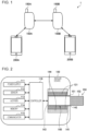
- Fig. 1 is a diagram illustrating a configuration example of a system 1 according to an embodiment of the present disclosure. As illustrated in Fig. 1 , the system 1 includes inhaler devices 100 (100A and 100B) and terminal devices 200 (200A and 200B).
- inhaler devices 100 100A and 100B
- terminal devices 200 200A and 200B
- Each inhaler device 100 is a device that generates a substance that is inhaled by a user.
- the substance generated by the inhaler device 100 will be described as being an aerosol.
- the inhaler device 100 is an example of an aerosol generation device that generates an aerosol.
- the substance generated by the inhaler device 100 may be a gas.
- the inhaler device 100 can accommodate a stick substrate 150.
- the inhaler device 100 uses the accommodated stick substrate 150 to generate an aerosol.
- the stick substrate 150 is an example of a substrate that contributes to the generation of an aerosol.
- the stick substrate 150 contains an aerosol source.
- the inhaler device 100 generates an aerosol by heating the accommodated stick substrate 150.
- Each terminal device 200 is a device used by the user of a corresponding one of the inhaler devices 100.
- the terminal device 200 is associated with the inhaler device 100.
- the inhaler device 100 and the terminal device 200 may have been paired in advance for wireless communication, or the fact that the user of the inhaler device 100 and the user of the terminal device 200 are identical may be registered in advance with a server that manages information on the inhaler device 100 and the terminal device 200.
- the terminal device 200 communicates with the inhaler device 100 associated with the terminal device 200 to configure operation settings of the inhaler device 100.
- the terminal device 200 may be any device, such as a smartphone, a tablet terminal, a wearable device, or a personal computer (PC). Alternatively, the terminal device 200 may be a charger that charges the inhaler device 100.
- the system 1 includes the inhaler devices 100 and the terminal devices 200 used by users.
- a user using the inhaler device 100A and the terminal device 200A is also referred to as user A.
- a user using the inhaler device 100B and the terminal device 200B is also referred to as user B.
- elements with substantially the same functional configuration may be distinguished by assigning the same reference numeral followed by different alphabet letters.
- multiple elements having substantially the same functional configuration are distinguished as needed, such as the inhaler device 100A and the inhaler device 100B.
- only the same reference numeral is assigned.
- the inhaler device 100A and the inhaler device 100B they are simply referred to as the inhaler devices 100.
- Fig. 2 is a schematic diagram schematically illustrating a configuration example of an inhaler device.
- the inhaler device 100 according to the present configuration example includes a power supply 111, a sensor 112, a notifier 113, a memory 114, a communicator 115, a controller 116, a heater 121, a container 140, and a heat insulator 144.
- the power supply 111 stores electric power.
- the power supply 111 supplies electric power to the structural elements of the inhaler device 100 under the control of the controller 116.
- the power supply 111 may be a rechargeable battery such as a lithium ion secondary battery.
- the sensor 112 acquires various items of information regarding the inhaler device 100.
- the sensor 112 detects a user action applied to the inhaler device 100.
- the sensor 112 may be a pressure sensor such as a condenser microphone, a flow sensor, or a temperature sensor, and acquire a value generated in accordance with the user's inhalation.
- the sensor 112 may be an input device that receives information input by the user, such as a button or a switch.
- the sensor 112 may have an inertial sensor, such as a gyroscope sensor or an acceleration sensor, and acquire a value associated with a change in the position or orientation of the inhaler device 100.
- the sensor 112 may detect an action such as a change in the position of a lid 14, which will be described later.
- the notifier 113 provides information to the user.
- the notifier 113 may be a light-emitting device that emits light, a display device that displays an image, a sound output device that outputs sound, or a vibration device that vibrates.
- the memory 114 stores various items of information for operation of the inhaler device 100.
- the memory 114 may be a non-volatile storage medium such as flash memory.
- the communicator 115 is a communication interface capable of communication in conformity with any wired or wireless communication standard.
- a communication standard may be, for example, Wi-Fi (registered trademark), Bluetooth (registered trademark), Bluetooth Low Energy (BLE) (registered trademark), near-field communication (NFC), or a standard using a low-power wide-area (LPWA).
- the controller 116 functions as an arithmetic processing unit and a control circuit, and controls the overall operations of the inhaler device 100 in accordance with various programs.
- the controller 116 is implemented by an electronic circuit such as a central processing unit (CPU) or a microprocessor, for example.
- the container 140 has an internal space 141, and holds the stick substrate 150 in a manner partially accommodated in the internal space 141.
- the container 140 has an opening 142 that allows the internal space 141 to communicate with outside.
- the container 140 accommodates the stick substrate 150 that is inserted into the internal space 141 through the opening 142.
- the container 140 is a tubular body having the opening 142 and a bottom 143 on its ends, and defines the pillar-shaped internal space 141.
- the container 140 connects with an airflow path that supplies air to the internal space 141.
- a side surface of the inhaler device 100 has an air inlet hole that is an inlet of air into the airflow path.
- the bottom 143 has an air outlet hole that is an outlet of the air from the airflow path to the internal space 141.
- the stick substrate 150 includes a substrate 151 and an inhalation port 152.
- the substrate 151 includes an aerosol source.
- the aerosol source includes a flavor component that is either derived from tobacco or not derived from tobacco.
- the aerosol source may include a medicine.
- the aerosol source may be a liquid including the flavor component that is either derived from tobacco or not derived from tobacco, such as polyhydric alcohol or water. Examples of the polyhydric alcohol include glycerine and propylene glycol.
- the aerosol source may be a solid including the flavor component that is either derived from tobacco or not derived from tobacco.
- the stick substrate 150 held by the container 140 includes the substrate 151 at least partially accommodated in the internal space 141 and the inhalation port 152 at least partially protruding from the opening 142.
- the inhalation port 152 protruding from the opening 142 in his/her mouth, air flows into the internal space 141 through the airflow path (not illustrated), and the air and an aerosol generated from the substrate 151 reach inside the mouth of the user.
- the heater 121 heats the aerosol source to atomize the aerosol source and generate the aerosol.
- the heater 121 has a film-like shape and surrounds the outer circumference of the container 140. Subsequently, heat produced from the heater 121 heats the substrate 151 of the stick substrate 150 from the outer circumference, generating the aerosol.
- the heater 121 produces heat when receiving electric power from the power supply 111.
- the electric power may be supplied in response to the sensor 112 detecting a start of the user's inhalation and/or an input of predetermined information. Subsequently, the supply of the electric power may be stopped in response to the sensor 112 detecting an end of the user's inhalation and/or an input of predetermined information.
- the heat insulator 144 prevents heat from transferring from the heater 121 to the other structural elements.
- the heat insulator 144 may be a vacuum heat insulator or an aerogel heat insulator.
- the configuration example of the inhaler device 100 has been described above.
- the inhaler device 100 is not limited to the above configuration, and may be configured in various ways as exemplified below.
- the heater 121 may have a blade-like shape, and may be disposed so that the heater 121 protrudes from the bottom 143 of the container 140 toward the internal space 141. In this case, the heater 121 having the blade-like shape is inserted into the substrate 151 of the stick substrate 150 and heats the substrate 151 of the stick substrate 150 from its inside. In another example, the heater 121 may be disposed so that the heater 121 covers the bottom 143 of the container 140. In still another example, the heater 121 may be implemented as a combination of two or more selected from a first heater that covers the outer circumference of the container 140, a second heater having the blade-like shape, and a third heater that covers the bottom 143 of the container 140.
- the container 140 may include an opening/closing mechanism that at least partially opens and closes an outer shell defining the internal space 141.
- the opening/closing mechanism include a hinge.
- the container 140 may accommodate the stick substrate 150 while sandwiching the stick substrate 150 inserted into the internal space 141 by opening and closing the outer shell.
- the heater 121 may be at the sandwiching position of the container 140 and may produce heat while pressing the stick substrate 150.
- means for atomizing the aerosol source is not limited to heating by the heater 121.
- the means for atomizing the aerosol source may be induction heating.
- the inhaler device 100 includes at least an electromagnetic induction source such as a coil that generates a magnetic field instead of the heater 121.
- the inhaler device 100 may be provided with a susceptor that produces heat by the induction heating, or the stick substrate 150 may include the susceptor.
- the heater 121 is an example of a generator that generates an aerosol using the stick substrate 150 accommodated in the container 140.
- Other examples of the generator include the above-mentioned electromagnetic induction source and/or susceptor.
- the inhaler device 100 cooperates with the stick substrate 150 to generate an aerosol to be inhaled by the user. Therefore, the combination of the inhaler device 100 and the stick substrate 150 may be conceived as an aerosol generation system.
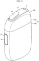
- Fig. 3 is an overall perspective view of the inhaler device 100 according to the present embodiment.
- Fig. 4 is an overall perspective view of the inhaler device 100 according to the present embodiment with the stick substrate 150 accommodated.
- the inhaler device 100 has a top housing 11A, a bottom housing 11B, a cover 12, a switch 13, the lid 14, a vent 15, and a cap 16.
- the top housing 11A and the bottom housing 11B are connected to each other to constitute an outer housing 11, which is the outermost of the inhaler device 100.
- the outer housing 11 is sized to fit into a user's hand. When using the inhaler device 100, the user can hold the inhaler device 100 in the user's hand and inhale the flavor.
- the top housing 11A has an opening which is not illustrated, and the cover 12 is coupled to the top housing 11A to close the opening.
- the cover 12 has the opening 142 through which the stick substrate 150 can be inserted.
- the lid 14 is configured to open and close the opening 142 of the cover 12.
- the lid 14 is attached to the cover 12 and is configured to be movable along the surface of the cover 12 between a first position for closing the opening 142 and a second position for opening the opening 142. This enables the lid 14 to allow or restrict access of the stick substrate 150 to the interior of the inhaler device 100 (the internal space 141 illustrated in Fig. 1 ).
- Opening the opening 142 using the lid 14 is hereinafter also referred to as opening the lid 14.
- closing the opening 142 using the lid 14 is also referred to as closing the lid 14.
- the switch 13 is used to switch on and off the actuation of the inhaler device 100.
- the user can operate the switch 13 with the stick substrate 150 inserted into the internal space 141 through the opening 142, thereby supplying electric power to the heater 121 from the power supply 111 and heating the stick substrate 150 without burning it.
- a flavored aerosol is generated from the aerosol source contained in the stick substrate 150.
- the user can inhale the flavored aerosol by inhaling the portion of the stick substrate 150 that protrudes from the inhaler device 100 (the portion illustrated in Fig. 4 , that is, the inhalation port 152).
- the vent 15 is a vent for introducing air into the internal space 141.
- the air drawn into the interior of the inhaler device 100 from the vent 15 is introduced into the internal space 141, for example, from the bottom 143 of the container 140.
- the cap 16 is configured to be detachable from the bottom housing 11B. With the cap 16 attached to the bottom housing 11B, the vent 15 is formed between the bottom housing 11B and the cap 16.
- the cap 16 may have, for example, a through hole or cutout that is not illustrated.
- the inhaler device 100 transmits and receives information wirelessly.
- the inhaler device 100 performs wireless communication in conformity with BLE.
- BLE will be described in detail.
- connection procedure between devices is specified as a protocol.
- a standardized method of using the protocol is defined as a profile.
- profiles There are two types of profiles: those standardized for each characteristic of the device, and those that are independent of the device's characteristics. The latter profiles are also referred to as generic profiles. Each generic profile operates as a lower layer beneath the profile for each characteristic of the device.
- GAP Generic Access Profile
- GAP is a generic profile that specifies procedures for enabling communication between devices.
- central and peripheral there are two types of roles for devices: central and peripheral.
- a central device is responsible for controlling communication.
- a peripheral device connects to and communicates with a central device based on the control by the central device.
- a peripheral device first broadcasts an advertising packet (hereinafter also referred to simply as advertisement).
- the peripheral device then waits to receive a connection request from a central device after transmitting the advertisement. Until the peripheral device receives a connection request, the peripheral device repeatedly transmits the advertisement and waits to receive a connection request.
- the advertisement is a signal that informs the destination of the advertisement about the existence of the transmission source of the advertisement.
- the advertisement may include various types of information, such as information about the peripheral device, information specifying the presence or absence of scanning, and information specifying the connection counterpart.
- the central device discovers the peripheral device by receiving the advertisement.
- the central device determines whether to allow a connection with the peripheral device based on the received advertisement.
- the central device may transmit a scan request, requesting the transmission of further additional information to determine whether to allow the connection.
- the peripheral device Upon receiving the scan request, the peripheral device transmits the requested additional information.
- the central device transmits a connection request to the peripheral device that the central device has permitted to connect, thereby establishing the connection.
- the method of waiting to receive an advertisement and receiving an advertisement from the surroundings is also referred to as passive scanning.
- the method of waiting to receive and receiving an advertisement from the surroundings and then requesting further additional information to be transmitted from the transmission source of the advertisement is also referred to as active scanning.
- GATT Generic Attribute Profile
- GATT is a generic profile that defines data transmission and reception, and the data structure.
- client and server there are two types of roles for devices: client and server.
- a client transmits a request to a server and receives a response from the server.
- a server receives a request from a client and sends a response. Either the server or the client may notify the other of information.
- a peripheral device acts as a server and a central device as a client, but the reverse is also possible.
- SM is a protocol for establishing security.
- GAP there are two types of roles for devices: initiator and responder.
- An initiator corresponds to a central device in GAP.
- a responder corresponds to a peripheral device in GAP.
- Pairing is a procedure for generating and exchanging a temporary encryption key. Pairing is performed within a connection established according to the procedures defined in GAP.
- bonding is defined. Bonding is a procedure performed after pairing to generate and exchange a permanent encryption key. The permanent encryption key is stored in each device. For subsequent connections, there is no need to perform bonding again, as the communication takes place using the stored permanent encryption key.
- Encryption re-establishment is the procedure for re-establishing a secure connection using the permanent encryption key stored through bonding.
- pairing refers to pairing with bonding and is a concept that encompasses both the pairing and bonding procedures described above.
- a connection refers to a secure connection using a permanent encryption key generated, exchanged, and stored through bonding.
- Fig. 5 is a diagram for describing the overview of the system 1 according to the present embodiment.
- the inhaler device 100A and the inhaler device 100B triggered by the opening by user A and user B of a lid 14A of the inhaler device 100A and a lid 14B of the inhaler device 100B almost at the same time, execute a connection procedure to establish a wireless connection.
- almost at the same time refers to the time difference being less than a predetermined threshold.
- the predetermined threshold may be approximately a few seconds; that is, almost at the same time is a concept that permits a time difference of approximately a few seconds.
- the inhaler device 100A and the inhaler device 100B transmit and receive information to be copied.
- the inhaler device 100A transmits information to be copied to the inhaler device 100B.
- the inhaler device 100B operates based on the information to be copied received from the inhaler device 100A, such as heating the stick substrate 150 based on the information to be copied.
- An example of the information to be copied is control information that defines the operation of the inhaler device 100. In that case, the inhaler device 100B can copy (that is, reproduce) the operation of the inhaler device 100A.
- the inhaler device 100 detects a predetermined user action applied to the inhaler device 100.
- the inhaler device 100 controls communication with another device based on the detected predetermined user action.
- the predetermined user action may be an action to open or close the lid 14. That is, the inhaler device 100 may control the connection procedure with another inhaler device 100 based on the action to open or close the lid 14.
- the inhaler device 100 then controls the transmission and reception of information to and from the other inhaler device 100 based on a change in the position or orientation of the inhaler device 100.
- the connection and transmission and reception of information between the inhaler device 100A and the inhaler device 100B can be executed with a simple action, without involving the terminal device 200A or the terminal device 200B.
- the predetermined user action is the action to open the lid 14.
- the inhaler device 100 may, triggered by the detection of the predetermined user action, that is, the opening of the lid 14, initiate a connection procedure with another inhaler device 100 as a connection counterpart.
- the connection procedure includes executing while alternately switching between transmitting an advertisement and waiting to receive an advertisement. That is, the inhaler device 100 operates by switching between functioning as a central device and as a peripheral device. This allows the inhaler device 100A and the inhaler device 100B to discover each other's presence and transmit and receive information about each other before establishing a connection. Note that waiting to receive an advertisement may be passive scanning or active scanning.
- the connection procedure includes a series of procedures for establishing a connection, including transmission of a connection request, pairing, bonding, etc. According to such a configuration, the user can initiate a connection procedure for the inhaler device 100 and another inhaler device 100 by simply opening the lid 14.
- the inhaler device 100 selects a connection counterpart.
- a connection counterpart is a device with which a connection is established for communication.
- selecting a connection counterpart may refer to selecting a connection counterpart based on information acquired before establishing a connection. That is, the inhaler device 100 may select a connection counterpart based on information acquired through passive scanning or active scanning.
- selecting a connection counterpart may refer to repeatedly establishing a connection on a trial basis and then, based on the information acquired from the established connection, either continuing or disconnecting the connection until a connection counterpart with which the connection will be continued is reached.
- the inhaler device 100 may select a connection counterpart based on the reception strength of the advertisement.
- An example of the reception strength is Received Signal Strength Indicator (RSSI).
- RSSI Received Signal Strength Indicator
- the inhaler device 100 may select the transmission source of the advertisement whose reception strength exceeds a predetermined threshold as a connection counterpart. However, if there are multiple transmission sources of advertisements whose reception strength exceeds the predetermined threshold, the inhaler device 100 may select a connection counterpart in descending order of the reception strength of the advertisements and attempt to establish a connection.
- the inhaler device 100A may select whether to set the inhaler device 100B as a connection counterpart based on information indicating the timing at which the predetermined user action was detected on the inhaler device 100A and information indicating the timing at which the predetermined user action was detected on the inhaler device 100B. That is, the inhaler device 100A may select whether to set the inhaler device 100B as a connection counterpart based on information indicating the timing at which the lid 14A of the inhaler device 100A opened and information indicating the timing at which the lid 14B of the inhaler device 100B opened.
- An example of information indicating the timing at which the lid 14 of the inhaler device 100 opened is the time at which the lid 14 of the inhaler device 100 opened, or the elapsed time since the opening of the lid 14 of the inhaler device 100.
- the inhaler device 100A may select the inhaler device 100B as a connection counterpart in the case where the time difference between the timing at which the lid 14A of the inhaler device 100A opened and the timing at which the lid 14B of the inhaler device 100B opened is less than a predetermined threshold.
- the inhaler device 100A may exclude the inhaler device 100B from being a connection counterpart in the case where the time difference between the timing at which the lid 14A of the inhaler device 100A opened and the timing at which the lid 14B of the inhaler device 100B opened is greater than or equal to the predetermined threshold. According to such a configuration, the inhaler device 100A and the inhaler device 100B can be connected exclusively when user A and user B open the lid 14A and the lid 14B almost at the same time with the intent to transmit and receive information to be copied.
- the inhaler device 100A may, in a connection procedure, transmit information indicating the timing at which the predetermined user action was detected on the inhaler device 100A, or receive information indicating the timing at which the predetermined user action was detected on the inhaler device 100B. That is, the inhaler device 100A may, in a connection procedure, transmit information indicating the timing at which the lid 14A of the inhaler device 100A opened, or receive information indicating the timing at which the lid 14B of the inhaler device 100B opened. In an example, the inhaler device 100A and the inhaler device 100B may, in passive scanning or active scanning, transmit and receive information indicating the timing at which the lid 14A opened and information indicating the timing at which the lid 14B opened. According to such a configuration, the inhaler device 100A and the inhaler device 100B can respectively check whether the other device is a suitable connection counterpart before establishing a connection.
- the inhaler device 100A may transmit information indicating the timing at which the predetermined user action was detected on the inhaler device 100A, or receive information indicating the timing at which the predetermined user action was detected on the inhaler device 100B. That is, in a connection established through a connection procedure, the inhaler device 100A may transmit information indicating the timing at which the lid 14A of the inhaler device 100A opened, or receive information indicating the timing at which the lid 14B of the inhaler device 100B opened.
- the inhaler device 100A and the inhaler device 100B may, after establishing a connection on a trial basis, transmit and receive information indicating the timing at which the lid 14A opened and information indicating the timing at which the lid 14B opened. According to such a configuration, the inhaler device 100A and the inhaler device 100B can respectively check whether the other device is a suitable connection counterpart after establishing a connection on a trial basis.
- the inhaler device 100 selects whether the inhaler device 100 operates as a controlling entity or as a controlled entity that operates based on the control by the controlling entity. That is, the inhaler device 100 selects its role as either a central or peripheral device. More specifically, the inhaler device 100 selects, in a connection procedure, whether to transmit a connection request as a central device or to wait to receive a connection request as a peripheral device.
- selecting the role may refer to selecting the role based on information acquired before establishing a connection. That is, the inhaler device 100 may select its role based on information acquired through passive scanning or active scanning.
- selecting the role may refer to, after selecting the role and establishing a connection on a trial basis, continuing or changing the role selected on a trial basis based on information acquired through the established connection.
- changing the role selected on a trial basis refers to disconnecting the connection and re-establishing a connection with the changed role.
- the inhaler device 100A may select whether to operate as a central device or to operate as a peripheral device based on information indicating the timing at which the predetermined user action was detected on the inhaler device 100A and information indicating the timing at which the predetermined user action was detected on the inhaler device 100B. That is, the inhaler device 100A may select whether to operate as a central device or to operate as a peripheral device based on information indicating the timing at which the lid 14A of the inhaler device 100A opened and information indicating the timing at which the lid 14B of the inhaler device 100B opened.
- the inhaler device 100A may select to operate as a central device in the case where the timing at which the lid 14A opened is earlier than the timing at which the lid 14B opened, and select to operate as a peripheral device otherwise.
- user A and user B can select the inhaler device 100 operating as a central or peripheral device by intentionally shifting the timings of the lid 14A and the lid 14B being opened. Therefore, for example, it facilitates the selection of the inhaler device 100A or 100B with a higher battery level or greater processing capability to function as the central device.
- the inhaler device 100A may select whether to operate as a central device or to operate as a peripheral device based on the identification information of the inhaler device 100A and the identification information of the inhaler device 100B.
- An example of the identification information is a serial number uniquely assigned to each inhaler device 100.
- the serial number may include information indicating the manufacturing period, such as an increasing number for newly manufactured inhaler devices 100. Additionally, the serial number may include information indicating the functionality of the inhaler device 100, such as including an alphabet letter according to the functionality of the inhaler device 100.
- the inhaler device 100A may be determined to operate as a central device in the case where its manufacturing period is older than the inhaler device 100B, and may be selected to operate as a peripheral device otherwise.
- the inhaler device 100A may be selected to operate as a central device in the case where the inhaler device 100A has better communication functionality than the inhaler device 100B, and to operate as a peripheral device otherwise. According to such a configuration, whether to operate as a central or peripheral device can be easily selected.
- the inhaler device 100A may transmit the identification information of the inhaler device 100A or receive the identification information of the inhaler device 100B.
- the inhaler device 100A and the inhaler device 100B may transmit and receive their serial numbers through passive scanning or active scanning. According to such a configuration, whether to operate as a central or peripheral device can be easily selected before establishing a connection.
- the inhaler device 100A may transmit the identification information of the inhaler device 100A or receive the identification information of the inhaler device 100B in a connection established through a connection procedure.
- the inhaler device 100A may, triggered by the detection of a first user action on the inhaler device 100A and the detection of a second user action corresponding to the first user action on the inhaler device 100B, transmit or receive information to be copied.
- the first user action and the second user action may be the same user action or different user actions.
- An example of the first user action or the second user action includes an action to change the position or orientation of the inhaler device 100, such as shaking the inhaler device 100 vertically or horizontally.
- user A and user B can execute the transmission and reception of information to be copied by respectively performing the corresponding user actions.
- the information to be copied can be transmitted and received exclusively when there is an explicit expression of intent to transmit and receive the information to be copied. Therefore, even if user A and user B happen to open the lids 14 almost at the same time, it is possible to prevent the information to be copied from being transmitted and received.
- the inhaler device 100A transmits information indicating the first user action detected on the inhaler device 100A or receives information indicating the second user action detected on the inhaler device 100B.
- An example of the information indicating the first user action includes information indicating time-series changes in acceleration and angular velocity of the inhaler device 100. The same applies to the information indicating the second user action.
- the inhaler device 100A determines whether the first user action and the second user action have been detected, and the inhaler device 100A can trigger the transmission and reception of the information to be copied.
- the inhaler device 100B determines whether the first user action and the second user action have been detected, and the inhaler device 100B can trigger the transmission and reception of the information to be copied.
- the inhaler device 100A may transmit the information indicating the first user action when operating as a peripheral device, and receive the information indicating the second user action when operating as a central device. That is, the central device determines whether the first user action and the second user action have been detected based on information received from the peripheral device, and the central device can trigger the transmission and reception of the information to be copied.
- the inhaler device 100A may select whether to transmit or receive the information to be copied based on information indicating the timing at which the predetermined user action was detected on the inhaler device 100A and information indicating the timing at which the predetermined user action was detected on the inhaler device 100B. That is, the inhaler device 100A may select whether to transmit or receive the information to be copied based on information indicating the timing at which the lid 14A of the inhaler device 100A opened and information indicating the timing at which the lid 14B of the inhaler device 100B opened. In an example, the inhaler device 100A may transmit the information to be copied in the case where the timing at which the lid 14A opened is earlier than the timing at which the lid 14B opened, and receive the information to be copied otherwise. According to such a configuration, user A and user B can select the direction in which the information to be copied is transmitted by intentionally shifting the timings of the lid 14A and the lid 14B being opened.
- the inhaler device 100A may select whether to transmit or receive the information to be copied when operating as a central device. In the meantime, the inhaler device 100A, when operating as a peripheral device, may transmit or receive the information to be copied based on the result of selecting a central device.
- the information to be copied may include at least one of first control information defining the operation of the heater 121 or second control information defining the operation of the notifier 113.
- the first control information may be a heating profile.
- a heating profile is control information for controlling the temperature at which the aerosol source is heated.
- a heating profile may be information defining a time series transition of the temperature of the heater 121.
- the inhaler device 100 causes the temperature of the heater 121 to transition as defined in the heating profile.
- the temperature at which the aerosol source is heated directly affects the flavor the user tastes. In this regard, making the heating profiles easily copyable between users allows the users to casually enjoy other users' favorite flavors.
- the second control information may be a notification setting.
- a notification setting is a combination of a condition and information to be provided when the condition is met.
- a notification setting directly affects the user experience of the inhaler device 100. In this regard, making the notification settings easily copyable between users allows the users to casually enjoy other users' favorite user experiences.
- the inhaler device 100 may, upon receiving the information to be copied, set the maximum number of times that the information to be copied can be used. That is, the inhaler device 100 may limit the number of operations based on the received control information. An example of the maximum number of times is once. For example, upon receiving heating profile A from the inhaler device 100A, the inhaler device 100B backs up heating profile B that was used up to that point and then executes heating based on heating profile A. Then, when the number of heating operations based on heating profile A reaches the maximum number of times, the inhaler device 100B deletes heating profile A and will execute heating based on heating profile B the next time.
- user B may operate the terminal device 200B to install heating profile A on the inhaler device 100B or to revoke the maximum number of times. According to such a configuration, the state before transmitting and receiving the information to be copied can be easily restored. Therefore, it is possible to reduce the psychological load of exchanging heating profiles or notification settings between users, allowing the users to casually enjoy new experiences.
- the inhaler device 100 may cancel the communication if a predetermined condition is met. Canceling the communication includes interrupting the connection procedure, disconnecting the already established connection, interrupting the transmission and reception of the information to be copied, and the like. More simply, canceling the communication may include turning off the communication function of the communicator 115.
- An example of the predetermined condition is heating the stick substrate 150. That is, the inhaler device 100 may cancel the communication when it is about to start heating the stick substrate 150 or is currently heating the stick substrate 150. According to such a configuration, it is possible to prevent an erroneous connection with another inhaler device 100 and the transmission and reception of the information to be copied, which is triggered by the user opening the lid 14 in order to insert and heat the stick substrate 150.
- Another example of the predetermined condition is detecting a cancel operation.
- An example of the cancel operation is the action to close the lid 14.
- the inhaler device 100 may restart the connection procedure when the lid 14 is opened the next time. According to such a configuration, in the case where the connection counterpart or the direction in which the information to be copied is transmitted differs from the user's intent, it is possible to restart the connection procedure.
- the inhaler device 100 provides various types of information to the user.
- the inhaler device 100 may cause the light-emitting device to emit light in a light-emitting pattern according to the provided information, and cause the vibration device to vibrate in a vibration pattern according to the provided information.
- the inhaler device 100 may provide information through the terminal device 200.
- the inhaler device 100 may provide information indicating a start of transmission or reception of the information to be copied or completion of transmission or reception of the information to be copied.
- the inhaler device 100A may provide information indicating the start of a connection procedure and the establishment of a connection. According to such a configuration, the user can easily grasp the communication status of the inhaler device 100.
- the inhaler device 100 may provide different information between the case of transmitting the information to be copied and the case of receiving the information to be copied.
- the inhaler device 100 causes the light-emitting device to emit light in different light-emitting patterns and/or causes the vibration device to vibrate in different vibration patterns between the case of transmitting the information to be copied and the case of receiving the information to be copied. According to such a configuration, the user can easily grasp the direction in which the information to be copied is transmitted.
- Fig. 6 is a sequence diagram illustrating an example of the flow of a process executed in the system 1 according to the present embodiment. In this sequence, the inhaler device 100A and the inhaler device 100B are involved.
- the inhaler device 100A detects an action on the lid 14A (step S102A).
- the inhaler device 100B detects an action on the lid 14B (step S102B).
- the inhaler device 100A triggered by the opening of the lid 14A, starts transmitting and waiting to receive an advertisement (step S104A).
- the inhaler device 100B triggered by the opening of the lid 14B, starts transmitting and waiting to receive an advertisement (step S104B).
- Each of the inhaler device 100A and the inhaler device 100B transmits an advertisement including its own serial number. Additionally, each of the inhaler device 100A and the inhaler device 100B measures RSSI of the received advertisement.
- the inhaler device 100A selects a connection counterpart (step S106A). For example, the inhaler device 100A selects the inhaler device 100B, which is the transmission source of the advertisement whose RSSI exceeds the predetermined threshold and is the highest, as a connection counterpart. Similarly, the inhaler device 100B selects a connection counterpart (step S106B). For example, the inhaler device 100B selects the inhaler device 100A, which is the transmission source of the advertisement whose RSSI exceeds the predetermined threshold and is the highest, as a connection counterpart.
- the inhaler device 100A and the inhaler device 100B select whether to operate as a central or peripheral device (steps S108A and S108B). For example, each of the inhaler device 100A and the inhaler device 100B selects to operate as a central device in the case where its own serial number is older than the serial number included in the received advertisement, and selects to operate as a peripheral device otherwise.
- Each of the inhaler device 100A and the inhaler device 100B then establishes a connection (step S110). For example, one of the inhaler device 100A and the inhaler device 100B that operates as a central device transmits a connection request, and the other operating as a peripheral device receives the connection request. Thereafter, the inhaler device 100A and the inhaler device 100B execute a series of procedures including pairing and bonding. Note that, if the connection is not established, such as in the case of a pairing failure, the process returns to steps S106A and S106B.
- the inhaler device 100A is the central device and the inhaler device 100B is the peripheral device is described. Operation by the peripheral device may be executed based on a request from the central device. However, the description of a request from the central device will be omitted below.
- the inhaler device 100B which is the peripheral device, transmits information indicating the timing at which the lid 14B opened to the inhaler device 100A, which is the central device (step S112).
- the inhaler device 100B may transmit, as information indicating the timing at which the lid 14B opened, either the time at which the lid 14B opened or the elapsed time from when the lid 14B opened until a connection is established (for instance, until pairing is completed).
- the inhaler device 100A determines whether the time difference between the timing at which the lid 14A was opened and the timing at which the lid 14B was opened is less than a predetermined threshold (step S114). In the case where it is determined that the time difference is less than the predetermined threshold, the process proceeds to the next. In contrast, in the case where it is determined that the time difference is greater than or equal to the predetermined threshold, the process returns to steps S106A and S106B.
- the predetermined threshold is five seconds, and the time difference is determined to be less than the predetermined threshold.
- the inhaler device 100A selects the direction in which the information to be copied is transmitted (step S116).
- the inhaler device 100A determines that the information to be copied is to be transmitted from the inhaler device 100A to the inhaler device 100B in the case where the timing at which the lid 14A opened is earlier than the timing at which the lid 14B opened.
- the inhaler device 100A determines that the information to be copied is to be transmitted from the inhaler device 100B to the inhaler device 100A in the case where the timing at which the lid 14A opened is later than the timing at which the lid 14B opened.
- the information to be copied is determined to be transmitted from the inhaler device 100A to the inhaler device 100B.
- the inhaler device 100A which is the transmission source of the information to be copied, notifies that it is ready to transmit (step S118A).
- the inhaler device 100B which is the destination of the information to be copied, notifies that it is ready to receive (step S118B). It is desirable that the notifications of transmission readiness and reception readiness differ, such as having different light-emitting patterns or vibration patterns.
- Each of the inhaler device 100A and the inhaler device 100B then detects a user action (steps S120A and S120B). For example, each of the inhaler device 100A and the inhaler device 100B detects time-series changes in acceleration and angular velocity. Note that, in the case where a cancel operation is detected on either the inhaler device 100A or the inhaler device 100B, the communication is canceled. In that case, the process returns to step S102A and S102B.
- the inhaler device 100B which is the peripheral device, transmits information indicating the detected user action to the inhaler device 100A (step S122).
- the inhaler device 100B transmits information indicating the detected time-series changes in acceleration and angular velocity.
- the inhaler device 100A which is the central device, then determines the consistency of the user actions (step S124). Determining the consistency of the user actions refers to determining whether the second user action corresponding to the first user action detected on the inhaler device 100A has been detected on the terminal device 200B.
- the inhaler device 100A determines the consistency of the user actions based on the time-series changes in acceleration and angular velocity detected in the inhaler device 100A as well as time-series changes in acceleration and angular velocity detected in the inhaler device 100B. In the case where the user actions are determined to be consistent (that is, in the case where it is determined that the second user action corresponding to the first user action has been detected), the process proceeds to the next. In contrast, in the case where the user actions are determined to be inconsistent, the process returns to steps S118A and S118B.
- the inhaler device 100A which is the transmission source of the information to be copied, transmits the information to be copied to the inhaler device 100B (step S126).
- the inhaler device 100A transmits the heating profile that the inhaler device 100A is using to the inhaler device 100B.
- the inhaler device 100A which is the transmission source of the information to be copied, then notifies that it has completed the transmission (step S128A).
- the inhaler device 100B which is the destination of the information to be copied, notifies that it has completed the reception (step S128B). It is desirable that the notifications of transmission completion and reception completion differ, such as having different light-emitting patterns or vibration patterns.
- the inhaler device 100A which is the central device, is the transmission source of the information to be copied; however, the present disclosure is not limited to such examples.
- the inhaler device 100B which is the peripheral device, may be the transmission source of the information to be copied.
- the inhaler devices 100 may notifier their users of the error and prompt the users to change the location or reopen the lids 14. Similarly, when the process returns to steps S118A and 118B, the inhaler devices 100 may notifier their users of the error and prompt the users to redo the first user action and the second user action.
- This specific example is an example of the case in which the inhaler device 100A and the inhaler device 100B are located at a close distance, and the lid 14A and the lid 14B are opened almost at the same time.
- Each of the inhaler devices 100A to 100D's advertisement reception strength is indicated in Table 1 below.
- the numerals in the table represent the RSSI in units of [dBm].
- the inhaler device 100A selects the inhaler device 100B, which is the transmission source of the advertisement whose RSSI exceeds the predetermined threshold, as a connection counterpart.
- the inhaler device 100B selects the inhaler device 100A, which is the transmission source of the advertisement whose RSSI exceeds the predetermined threshold, as a connection counterpart.
- the inhaler device 100A and the inhaler device 100B based on their serial numbers, determine that the inhaler device 100A is a central device and the inhaler device 100B is a peripheral device. Then, the inhaler device 100A transmits a connection request and establishes a connection with the inhaler device 100B.
- the inhaler device 100A receives information indicating the timing at which the lid 14B of the inhaler device 100B was opened, and, based on the time difference between the timings at which the lid 14A and the lid 14B were opened, confirms that the inhaler device 100B is a suitable connection counterpart.
- This specific example is an example in which the inhaler device 100A, inhaler device 100B, and inhaler device 100D are located at close distances. Note that, in this specific example, it is assumed that, although the lid 14A and the lid 14B were opened almost at the same time, a lid 14D of the inhaler device 100D was opened at a timing that greatly differs from the lid 14A and the lid 14B.
- Each of the inhaler devices 100A to 100D's advertisement reception strength is indicated in Table 2 below. The numerals in the table represent the RSSI in units of [dBm].
- the inhaler device 100A selects the inhaler device 100D, which is the transmission source of the advertisement whose RSSI exceeds the predetermined threshold and is the highest, as a connection counterpart.
- the inhaler device 100B selects the inhaler device 100A, which is the transmission source of the advertisement whose RSSI exceeds the predetermined threshold and is the highest, as a connection counterpart.
- the inhaler device 100D selects the inhaler device 100A, which is the transmission source of the advertisement whose RSSI exceeds the predetermined threshold and is the highest, as a connection counterpart.
- the inhaler device 100A and the inhaler device 100D first try to establish a connection. That is, the inhaler device 100A and the inhaler device 100D, based on their serial numbers, determine that the inhaler device 100A is a central device and the inhaler device 100D is a peripheral device. Then, the inhaler device 100A transmits a connection request and establishes a connection with the inhaler device 100D. Thereafter, the inhaler device 100A receives information indicating the timing at which the lid 14D of the inhaler device 100D was opened, and, based on the time difference between the timings at which the lid 14A and the lid 14D were opened, confirms that the inhaler device 100D is an unsuitable connection counterpart. Thus, the inhaler device 100A disconnects from the inhaler device 100D.
- the inhaler device 100A selects the inhaler device 100B, which is the transmission source of the advertisement whose RSSI exceeds the predetermined threshold and is the second highest, as a connection counterpart. Then, the inhaler device 100A tries to establish a connection with the inhaler device 100B.
- the subsequent process is as described above in the first specific example.
- This specific example is an example in the same environment as the second specific example, but the advertisement reception strengths are different from the second specific example.
- Each of the inhaler devices 100A to 100D's advertisement reception strength is indicated in Table 3 below.
- the numerals in the table represent the RSSI in units of [dBm].
- the inhaler device 100A selects the inhaler device 100D, which is the transmission source of the advertisement whose RSSI exceeds the predetermined threshold and is the highest, as a connection counterpart.
- the inhaler device 100B selects the inhaler device 100D, which is the transmission source of the advertisement whose RSSI exceeds the predetermined threshold and is the highest, as a connection counterpart.
- the inhaler device 100D selects the inhaler device 100A, which is the transmission source of the advertisement whose RSSI exceeds the predetermined threshold and is the highest, as a connection counterpart.
- the inhaler device 100A and the inhaler device 100D first try to establish a connection.
- the inhaler device 100A and the inhaler device 100D determine that the inhaler device 100A is a central device and the inhaler device 100D is a peripheral device. Then, the inhaler device 100A transmits a connection request and establishes a connection with the inhaler device 100D. Thereafter, the inhaler device 100A receives information indicating the timing at which the lid 14D of the inhaler device 100D was opened, and, based on the time difference between the timings at which the lid 14A and the lid 14D were opened, confirms that the inhaler device 100D is an unsuitable connection counterpart. Thus, the inhaler device 100A disconnects from the inhaler device 100D.
- the inhaler device 100D selects the inhaler device 100B, which is the transmission source of the advertisement whose RSSI exceeds the predetermined threshold and is the second highest, as a connection counterpart. Then, the inhaler device 100D tries to establish a connection with the inhaler device 100B. The attempt to connect the inhaler device 100B and the inhaler device 100D ends in failure, following a similar flow to the attempt to connect the inhaler device 100A and the inhaler device 100D.
- the inhaler device 100A and the inhaler device 100B have excluded the inhaler device 100D from being a connection counterpart.
- the inhaler device 100A selects the inhaler device 100B, which is the transmission source of the advertisement whose RSSI exceeds the predetermined threshold and is the second highest, as a connection counterpart.
- the inhaler device 100B selects the inhaler device 100A, which is the transmission source of the advertisement whose RSSI exceeds the predetermined threshold and is the second highest, as a connection counterpart.
- the inhaler device 100A and the inhaler device 100B try to establish a connection.
- the subsequent process is as described above in the first specific example.
- the inhaler device 100 may, triggered by the opening of the lid 14, initiate a connection procedure not only with another inhaler device 100 but also with the terminal device 200. Therefore, it is desirable to have the capability to control which connection counterpart to prioritize when the lid 14 opens, whether it be another inhaler device 100 or the terminal device 200.
- the inhaler device 100 selects a connection counterpart exclusively from another inhaler device 100 when operating in a first operating mode (corresponding to a predetermined operating mode). That is, the inhaler device 100, when operating in the first operating mode, excludes the terminal device 200 from being a connection counterpart.
- the inhaler device 100 may, when operating in a second operating mode, select a connection counterpart exclusively from the terminal device 200. That is, the inhaler device 100 may, when operating in the second operating mode, exclude another inhaler device 100 from being a connection counterpart.
- the inhaler device 100 can, based on a serial number included in an advertisement, determine whether the transmission source of the advertisement is another inhaler device 100 or the terminal device 200, and determine whether it is a suitable connection counterpart. According to such a configuration, the inhaler device 100 can select a suitable connection counterpart.
- the inhaler device 100 may operate in the first operating mode in response to detection of a third user action. That is, the inhaler device 100 may select a connection counterpart exclusively from another inhaler device 100 in response to detection of the third user action. In contrast, the inhaler device 100 may operate in the second operating mode when no third user action is detected. That is, the inhaler device 100 may select a connection counterpart exclusively from the terminal device 200 when no third user action is detected.
- the inhaler device 100 may detect the third user action within a predetermined time after the opening of the lid 14.
- An example of the third user action is the action to change the position or orientation of the inhaler device 100, such as shaking the inhaler device 100 vertically or horizontally. According to such a configuration, the user can easily select which connection counterpart to set, either another inhaler device 100 or the terminal device 200, depending on whether or not the user performs the third user action.
- the inhaler device 100 may provide information indicating the operating mode. According to such a configuration, the user can easily grasp the operating mode of the inhaler device 100.
- detection of the first user action and the second user action may be omitted. That is, after the connection between the inhaler device 100A and the inhaler device 100B has been established, information to be copied may be transmitted and received even if the first user action and the second user action are not performed.
- An explicit expression of intent to transmit and receive information to be copied, which can be conveyed through the first user action and the second user action, is substitutable by the third user action. According to such a configuration, the user's operation load can be reduced.
- Fig. 7 is a sequence diagram illustrating an example of the flow of a process executed in the system 1 according to the present modification. In this sequence, the inhaler device 100A and the inhaler device 100B are involved.
- steps S202A and S202B to steps S204A and S204B is the same as the process according to steps S102A and S102B to steps S104A and S104B described above with reference to Fig. 6 .
- the inhaler device 100A and the inhaler device 100B detect the third user action (steps S206A and S206B). For example, the inhaler device 100A detects the action to shake the inhaler device 100A vertically or horizontally three times as the third user action. The inhaler device 100B also detects the action to shake the inhaler device 100B vertically or horizontally three times as the third user action.
- the inhaler device 100A and the inhaler device 100B then select the first operating mode (steps S208A and S208B).
- the inhaler device 100A and the inhaler device 100B provide information indicating that they are to operate in the first operating mode (steps S210A and S210B).
- the inhaler device 100A selects a connection counterpart (step S212A). For example, the inhaler device 100A selects the inhaler device 100B, which is the transmission source of the advertisement whose RSSI exceeds the predetermined threshold and is the highest, and which includes a serial number as the inhaler device 100 as a connection counterpart. Similarly, the inhaler device 100B selects a connection counterpart (step S212B). For example, the inhaler device 100B selects the inhaler device 100A, which is the transmission source of the advertisement whose RSSI exceeds the predetermined threshold and is the highest, and which includes a serial number as the inhaler device 100 as a connection counterpart.
- steps S214A and S214B to steps S224A and S224B is the same as the process according to steps S108A and S108B to steps S118A and S118B described above with reference to Fig. 6 .
- the inhaler device 100A and the inhaler device 100B may provide a grace period of about ten seconds for accepting a cancel operation in steps S224A and S224B. In this grace period, if a cancel operation is detected in either the inhaler device 100A or the inhaler device 100B, the communication is canceled. In that case, the process returns to steps S202A and S202B.
- steps S226 to S228A and S228B is the same as the process according to steps S126 to S128A and S128B described above with reference to Fig. 6 .
- Fig. 8 is a diagram for describing the overview of an aerosol generation system 2 according to a second modification.
- the aerosol generation system 2 according to the present modification includes the inhaler device 100 (an example of a first device) and a charger 300 (an example of a second device).
- the internal configuration of the inhaler device 100 is the same as the configuration described above with reference to Fig. 2 .
- the charger 300 is a device configured to charge the inhaler device 100.
- the charger 300 is connectable to the inhaler device 100. When the inhaler device 100 is connected, the charger 300 charges the inhaler device 100.
- the charger 300 stops charging the inhaler device 100.
- the charger 300 has a power supply that stores electric power, a charging terminal that can be connected to the inhaler device 100, and a controller that executes power supply from the power supply to the inhaler device 100 when the inhaler device 100 is connected to the charging terminal.
- the charger 300 may be configured to be capable of accommodating the inhaler device 100 while being connected to the inhaler device 100.
- the charger 300 may have a communicator that transmits and receives information wirelessly.
- the charger 300 may be wirelessly connected to another aerosol generation system 2 (that is, another inhaler device 100 or another charger 300).
- the controller 116 of the inhaler device 100 may control a connection procedure with another aerosol generation system 2 by the communicator of the charger 300.
- the controller of the charger 300 may control a connection procedure with another aerosol generation system 2 by the communicator of the charger 300.
- the inhaler device 100 may be wirelessly connected to another aerosol generation system 2 (that is, another inhaler device 100 or another charger 300).
- the controller 116 of the inhaler device 100 may control a connection procedure with another aerosol generation system 2 by the communicator 115 of the inhaler device 100.
- the controller of the charger 300 may control a connection procedure with another aerosol generation system 2 by the communicator 115 of the inhaler device 100.
- the inhaler device 100 controls a connection procedure with another inhaler device 100 based on a detected predetermined user action.
- the predetermined user action is the action to open or close the lid 14; however, the present disclosure is not limited to such examples.
- the predetermined action may be the action to press a button provided on the inhaler device 100.
- a button provided on the inhaler device 100.
- An example of the button is the switch 13 illustrated in Figs. 3 and 4 . It is acceptable for the button to be provided on the charger 300.
- the predetermined action may be the action to disconnect the inhaler device 100 and the charger 300, or the action to connect the inhaler device 100 and the charger 300.
- the predetermined action may be the action to start charging the inhaler device 100, or the action to stop charging the inhaler device 100.
- the predetermined user action may include one or more of the actions exemplified above. That is, the inhaler device 100 may control a connection procedure with another inhaler device 100 based on the detection of the action to open the lid 14, the action to close the lid 14, the action to press the switch 13, the action to disconnect the inhaler device 100 and the charger 300, or the action to connect the inhaler device 100 and the charger 300.
- the above embodiment describes an example in which the inhaler device 100 performs communication in conformity with BLE; however, the present disclosure is not limited to such examples.
- the inhaler device 100 may perform communication in conformity with any wireless communication standard, such as Wi-Fi.
- the above embodiment describes an example in which the inhaler device 100 heats the stick substrate 150 to generate an aerosol; however, the present disclosure is not limited to such examples.
- the inhaler device 100 may be configured as a so-called liquid atomization type aerosol generator that generates an aerosol by heating and atomizing an aerosol source as a liquid.
- the technology of the present disclosure is also applicable to a liquid atomization type aerosol generator.
- each of the devices described herein may be implemented as a single device, or some or all of them may be implemented as separate devices.
- the inhaler device 100 as an aerosol generation system may be implemented as multiple devices.
- part of the functions of the communicator 115 and the controller 116 of the inhaler device 100 described above with reference to Fig. 2 may be provided in a device other than the inhaler device 100. More specifically, the function of performing communication in conformity with BLE and the function of controlling communication in conformity with BLE may be provided in a charger that charges the inhaler device 100.
- each of the devices described herein may be implemented using software, hardware, and a combination of software and hardware.
- Programs constituting the software are pre-stored, for example, on a recording medium (specifically, a computer-readable non-transitory storage medium) provided inside or outside each device.
- a recording medium specifically, a computer-readable non-transitory storage medium
- Each program is then loaded into a RAM upon execution by, for example, a computer controlling each device described herein, and executed by a processing circuit, such as a CPU.
- the recording medium includes, for example, a magnetic disk, an optical disk, a magneto-optical disk, a flash memory, and the like.
- the computer programs mentioned above may also be delivered, for example, over a network, without the use of a recording medium.
- the computer mentioned above may be an application-specific integrated circuit such as an ASIC, a general-purpose processor that executes functions by loading software programs, a computer on a server used for cloud computing, or the like. Also, a series of processes performed by each device described herein may be distributed among and processed by multiple computers.
Landscapes
- Engineering & Computer Science (AREA)
- Computer Networks & Wireless Communication (AREA)
- Signal Processing (AREA)
- Mobile Radio Communication Systems (AREA)
- Selective Calling Equipment (AREA)
- Information Transfer Between Computers (AREA)
Abstract
Description
- The present disclosure relates to an aerosol generation system and a control method.
- Inhaler devices, such as electronic cigarettes and nebulizers, which generate substances for users to inhale, are widespread. For example, an inhaler device uses a substrate that includes an aerosol source for generating an aerosol and a flavor source for imparting a flavor component to the generated aerosol, thus producing an aerosol with an added flavor component. The user can taste the smoke taste by inhaling the aerosol generated by the inhaler device with the added flavor component. The action of the user inhaling the aerosol is hereinafter referred to as a puff or a puff action.
- In recent years, it has been considered to equip inhaler devices with a communication function. For example,
Patent Literature 1 below discloses technology for detachably attaching an accessory having a communication function to an inhaler device. - Patent Literature 1:
JP 2021-121191 A - However, the technology disclosed in
Patent Literature 1 above is still relatively new, and there remains room for improvement from various perspectives. - Accordingly, the present disclosure has been made in view of the above problem, and it is an object of the present disclosure to provide a mechanism capable of improving usability regarding communication.
- In order to solve the above problem, according to one aspect of the present invention, there is provided an aerosol generation system including: a generator that generates an aerosol using a substrate containing an aerosol source; a communicator that transmits and receives information wirelessly; a sensor that detects a user action applied to the aerosol generation system; and a controller that controls a connection procedure with another aerosol generation system by the communicator based on a predetermined user action detected by the sensor.
- The aerosol generation system may include a container that has an opening through which the substrate can be inserted and accommodates the substrate inserted through the opening, and a lid that opens and closes the opening, and the predetermined user action may include an action to open or close the lid.
- The controller may, triggered by detection of the predetermined user action, control the communicator to initiate the connection procedure with the another aerosol generation system as a connection counterpart, and the connection procedure may include executing while alternately switching between transmitting an advertisement and waiting to receive an advertisement.
- The controller may select whether to set the another aerosol generation system as a connection counterpart based on information indicating a timing at which the predetermined user action was detected in the aerosol generation system and information indicating a timing at which the predetermined user action was detected in the another aerosol generation system.
- The controller may select whether to transmit or receive information to be copied based on information indicating a timing at which the predetermined user action was detected in the aerosol generation system and information indicating a timing at which the predetermined user action was detected in the another aerosol generation system.
- The controller may select whether the aerosol generation system operates as a controlling entity or as a controlled entity that operates under control of the controlling entity, based on information indicating a timing at which the predetermined user action was detected in the aerosol generation system and information indicating a timing at which the predetermined user action was detected in the another aerosol generation system.
- The communicator may, in the connection procedure, transmit information indicating a timing at which the predetermined user action was detected in the aerosol generation system or receive information indicating a timing at which the predetermined user action was detected in the another aerosol generation system.
- The communicator may, in a connection established through the connection procedure, transmit information indicating a timing at which the predetermined user action was detected in the aerosol generation system or receive information indicating a timing at which the predetermined user action was detected in the another aerosol generation system.
- The controller may select, based on identification information of the aerosol generation system and identification information of the another aerosol generation system, whether the aerosol generation system operates as a controlling entity or as a controlled entity that operates under control of the controlling entity.
- The communicator may transmit the identification information of the aerosol generation system or receive the identification information of the another aerosol generation system in the connection procedure.
- The controller may, triggered by detection of a first user action in the aerosol generation system and detection of a second user action corresponding to the first user action in the another aerosol generation system, control the communicator to transmit or receive information to be copied.
- The communicator may transmit information indicating the first user action detected in the aerosol generation system or receive information indicating the second user action detected in the another aerosol generation system.
- The aerosol generation system may further include a notifier that provides information, and the controller may control the notifier to provide information indicating a start of transmission or reception of the information to be copied or completion of transmission or reception of the information to be copied.
- The controller may control the notifier to provide different information between a case of transmitting the information to be copied and a case of receiving the information to be copied.
- The information to be copied may include at least one of first control information defining an operation of the generator or second control information defining an operation of the notifier.
- The controller may, upon receiving the information to be copied, set a maximum number of times that the information to be copied can be used.
- The controller may select a connection counterpart exclusively from the another aerosol generation system in response to detection of a third user action.
- The aerosol generation system may include a first device including the generator and a second device capable of connecting to the first device, and the predetermined user action may include an action to disconnect the first device and the second device or connect the first device and the second device.
- The aerosol generation system may further include a button, and the predetermined user action may include an action to press the button.
- Additionally, in order to solve the above problem, according to another aspect of the present invention, there is provided a control method executed by a computer that controls an aerosol generation system, the aerosol generation system including a generator that generates an aerosol using a substrate containing an aerosol source, a communicator that transmits and receives information wirelessly, and a sensor that detects a user action applied to the aerosol generation system, the control method including: controlling a connection procedure with another aerosol generation system by the communicator based on a predetermined user action detected by the sensor.
- As described above, according to the present disclosure, a mechanism capable of improving usability regarding communication is provided.
-
- [
Fig. 1] Fig. 1 is a diagram illustrating a configuration example of a system according to an embodiment of the present disclosure. - [
Fig. 2] Fig. 2 is a schematic diagram schematically illustrating a configuration example of an inhaler device. - [
Fig. 3] Fig. 3 is an overall perspective view of the inhaler device according to the present embodiment. - [
Fig. 4] Fig. 4 is an overall perspective view of the inhaler device according to the present embodiment with a stick substrate held. - [
Fig. 5] Fig. 5 is a diagram for describing the overview of the system according to the present embodiment. - [
Fig. 6] Fig. 6 is a sequence diagram illustrating an example of the flow of a process executed in the system according to the present embodiment. - [
Fig. 7] Fig. 7 is a sequence diagram illustrating an example of the flow of a process executed in the system according to a first modification. - [
Fig. 8] Fig. 8 is a diagram for describing the overview of an aerosol generation system according to a second modification. - A preferred embodiment of the present disclosure will be described in detail below with reference to the accompanying drawings. Note that, in the present specification and drawings, structural elements having substantially the same functional configuration are denoted by the same reference numeral and overlapping descriptions are omitted.
-
Fig. 1 is a diagram illustrating a configuration example of asystem 1 according to an embodiment of the present disclosure. As illustrated inFig. 1 , thesystem 1 includes inhaler devices 100 (100A and 100B) and terminal devices 200 (200A and 200B). - Each
inhaler device 100 is a device that generates a substance that is inhaled by a user. Hereinafter, the substance generated by theinhaler device 100 will be described as being an aerosol. Theinhaler device 100 is an example of an aerosol generation device that generates an aerosol. Alternatively, the substance generated by theinhaler device 100 may be a gas. Theinhaler device 100 can accommodate astick substrate 150. Theinhaler device 100 uses the accommodatedstick substrate 150 to generate an aerosol. Thestick substrate 150 is an example of a substrate that contributes to the generation of an aerosol. Thestick substrate 150 contains an aerosol source. Theinhaler device 100 generates an aerosol by heating the accommodatedstick substrate 150. - Each terminal device 200 is a device used by the user of a corresponding one of the
inhaler devices 100. The terminal device 200 is associated with theinhaler device 100. Theinhaler device 100 and the terminal device 200 may have been paired in advance for wireless communication, or the fact that the user of theinhaler device 100 and the user of the terminal device 200 are identical may be registered in advance with a server that manages information on theinhaler device 100 and the terminal device 200. The terminal device 200 communicates with theinhaler device 100 associated with the terminal device 200 to configure operation settings of theinhaler device 100. The terminal device 200 may be any device, such as a smartphone, a tablet terminal, a wearable device, or a personal computer (PC). Alternatively, the terminal device 200 may be a charger that charges theinhaler device 100. - The
system 1 includes theinhaler devices 100 and the terminal devices 200 used by users. In an example, a user using theinhaler device 100A and theterminal device 200A is also referred to as user A. Additionally, a user using theinhaler device 100B and theterminal device 200B is also referred to as user B. - Note that, in the present specification and the drawings, elements with substantially the same functional configuration may be distinguished by assigning the same reference numeral followed by different alphabet letters. For example, multiple elements having substantially the same functional configuration are distinguished as needed, such as the
inhaler device 100A and theinhaler device 100B. However, if it is not necessary to particularly distinguish each of multiple elements having substantially the same functional configuration, only the same reference numeral is assigned. For example, if it is not necessary to particularly distinguish between theinhaler device 100A and theinhaler device 100B, they are simply referred to as theinhaler devices 100. -
Fig. 2 is a schematic diagram schematically illustrating a configuration example of an inhaler device. As illustrated inFig. 2 , theinhaler device 100 according to the present configuration example includes apower supply 111, asensor 112, anotifier 113, amemory 114, acommunicator 115, acontroller 116, aheater 121, acontainer 140, and aheat insulator 144. - The
power supply 111 stores electric power. Thepower supply 111 supplies electric power to the structural elements of theinhaler device 100 under the control of thecontroller 116. Thepower supply 111 may be a rechargeable battery such as a lithium ion secondary battery. - The
sensor 112 acquires various items of information regarding theinhaler device 100. In particular, thesensor 112 detects a user action applied to theinhaler device 100. In an example, thesensor 112 may be a pressure sensor such as a condenser microphone, a flow sensor, or a temperature sensor, and acquire a value generated in accordance with the user's inhalation. In another example, thesensor 112 may be an input device that receives information input by the user, such as a button or a switch. In another example, thesensor 112 may have an inertial sensor, such as a gyroscope sensor or an acceleration sensor, and acquire a value associated with a change in the position or orientation of theinhaler device 100. In another example, thesensor 112 may detect an action such as a change in the position of alid 14, which will be described later. - The
notifier 113 provides information to the user. Thenotifier 113 may be a light-emitting device that emits light, a display device that displays an image, a sound output device that outputs sound, or a vibration device that vibrates. - The
memory 114 stores various items of information for operation of theinhaler device 100. Thememory 114 may be a non-volatile storage medium such as flash memory. - The
communicator 115 is a communication interface capable of communication in conformity with any wired or wireless communication standard. Such a communication standard may be, for example, Wi-Fi (registered trademark), Bluetooth (registered trademark), Bluetooth Low Energy (BLE) (registered trademark), near-field communication (NFC), or a standard using a low-power wide-area (LPWA). - The
controller 116 functions as an arithmetic processing unit and a control circuit, and controls the overall operations of theinhaler device 100 in accordance with various programs. Thecontroller 116 is implemented by an electronic circuit such as a central processing unit (CPU) or a microprocessor, for example. - The
container 140 has aninternal space 141, and holds thestick substrate 150 in a manner partially accommodated in theinternal space 141. Thecontainer 140 has anopening 142 that allows theinternal space 141 to communicate with outside. Thecontainer 140 accommodates thestick substrate 150 that is inserted into theinternal space 141 through theopening 142. For example, thecontainer 140 is a tubular body having theopening 142 and a bottom 143 on its ends, and defines the pillar-shapedinternal space 141. Thecontainer 140 connects with an airflow path that supplies air to theinternal space 141. For example, a side surface of theinhaler device 100 has an air inlet hole that is an inlet of air into the airflow path. For example, the bottom 143 has an air outlet hole that is an outlet of the air from the airflow path to theinternal space 141. - The
stick substrate 150 includes asubstrate 151 and aninhalation port 152. Thesubstrate 151 includes an aerosol source. The aerosol source includes a flavor component that is either derived from tobacco or not derived from tobacco. For theinhaler device 100 that is a medical inhaler such as a nebulizer, the aerosol source may include a medicine. For example, the aerosol source may be a liquid including the flavor component that is either derived from tobacco or not derived from tobacco, such as polyhydric alcohol or water. Examples of the polyhydric alcohol include glycerine and propylene glycol. Alternatively, the aerosol source may be a solid including the flavor component that is either derived from tobacco or not derived from tobacco. Thestick substrate 150 held by thecontainer 140 includes thesubstrate 151 at least partially accommodated in theinternal space 141 and theinhalation port 152 at least partially protruding from theopening 142. When the user inhales with theinhalation port 152 protruding from theopening 142 in his/her mouth, air flows into theinternal space 141 through the airflow path (not illustrated), and the air and an aerosol generated from thesubstrate 151 reach inside the mouth of the user. - The
heater 121 heats the aerosol source to atomize the aerosol source and generate the aerosol. In the example illustrated inFig. 2 , theheater 121 has a film-like shape and surrounds the outer circumference of thecontainer 140. Subsequently, heat produced from theheater 121 heats thesubstrate 151 of thestick substrate 150 from the outer circumference, generating the aerosol. Theheater 121 produces heat when receiving electric power from thepower supply 111. In an example, the electric power may be supplied in response to thesensor 112 detecting a start of the user's inhalation and/or an input of predetermined information. Subsequently, the supply of the electric power may be stopped in response to thesensor 112 detecting an end of the user's inhalation and/or an input of predetermined information. - The
heat insulator 144 prevents heat from transferring from theheater 121 to the other structural elements. For example, theheat insulator 144 may be a vacuum heat insulator or an aerogel heat insulator. - The configuration example of the
inhaler device 100 has been described above. Theinhaler device 100 is not limited to the above configuration, and may be configured in various ways as exemplified below. - In an example, the
heater 121 may have a blade-like shape, and may be disposed so that theheater 121 protrudes from thebottom 143 of thecontainer 140 toward theinternal space 141. In this case, theheater 121 having the blade-like shape is inserted into thesubstrate 151 of thestick substrate 150 and heats thesubstrate 151 of thestick substrate 150 from its inside. In another example, theheater 121 may be disposed so that theheater 121 covers thebottom 143 of thecontainer 140. In still another example, theheater 121 may be implemented as a combination of two or more selected from a first heater that covers the outer circumference of thecontainer 140, a second heater having the blade-like shape, and a third heater that covers thebottom 143 of thecontainer 140. - In another example, the
container 140 may include an opening/closing mechanism that at least partially opens and closes an outer shell defining theinternal space 141. Examples of the opening/closing mechanism include a hinge. In addition, thecontainer 140 may accommodate thestick substrate 150 while sandwiching thestick substrate 150 inserted into theinternal space 141 by opening and closing the outer shell. In this case, theheater 121 may be at the sandwiching position of thecontainer 140 and may produce heat while pressing thestick substrate 150. - In addition, means for atomizing the aerosol source is not limited to heating by the
heater 121. For example, the means for atomizing the aerosol source may be induction heating. In this case, theinhaler device 100 includes at least an electromagnetic induction source such as a coil that generates a magnetic field instead of theheater 121. Theinhaler device 100 may be provided with a susceptor that produces heat by the induction heating, or thestick substrate 150 may include the susceptor. - Note that the
heater 121 is an example of a generator that generates an aerosol using thestick substrate 150 accommodated in thecontainer 140. Other examples of the generator include the above-mentioned electromagnetic induction source and/or susceptor. - The
inhaler device 100 cooperates with thestick substrate 150 to generate an aerosol to be inhaled by the user. Therefore, the combination of theinhaler device 100 and thestick substrate 150 may be conceived as an aerosol generation system. -
Fig. 3 is an overall perspective view of theinhaler device 100 according to the present embodiment.Fig. 4 is an overall perspective view of theinhaler device 100 according to the present embodiment with thestick substrate 150 accommodated. - As illustrated in
Figs. 3 and4 , theinhaler device 100 has atop housing 11A, abottom housing 11B, acover 12, aswitch 13, thelid 14, avent 15, and acap 16. Thetop housing 11A and thebottom housing 11B are connected to each other to constitute anouter housing 11, which is the outermost of theinhaler device 100. Theouter housing 11 is sized to fit into a user's hand. When using theinhaler device 100, the user can hold theinhaler device 100 in the user's hand and inhale the flavor. - The
top housing 11A has an opening which is not illustrated, and thecover 12 is coupled to thetop housing 11A to close the opening. As illustrated inFig. 4 , thecover 12 has theopening 142 through which thestick substrate 150 can be inserted. Thelid 14 is configured to open and close theopening 142 of thecover 12. Specifically, thelid 14 is attached to thecover 12 and is configured to be movable along the surface of thecover 12 between a first position for closing theopening 142 and a second position for opening theopening 142. This enables thelid 14 to allow or restrict access of thestick substrate 150 to the interior of the inhaler device 100 (theinternal space 141 illustrated inFig. 1 ). Opening theopening 142 using thelid 14 is hereinafter also referred to as opening thelid 14. Additionally, closing theopening 142 using thelid 14 is also referred to as closing thelid 14. - The
switch 13 is used to switch on and off the actuation of theinhaler device 100. For example, as illustrated inFig. 4 , the user can operate theswitch 13 with thestick substrate 150 inserted into theinternal space 141 through theopening 142, thereby supplying electric power to theheater 121 from thepower supply 111 and heating thestick substrate 150 without burning it. Once thestick substrate 150 is heated, a flavored aerosol is generated from the aerosol source contained in thestick substrate 150. The user can inhale the flavored aerosol by inhaling the portion of thestick substrate 150 that protrudes from the inhaler device 100 (the portion illustrated inFig. 4 , that is, the inhalation port 152). - The
vent 15 is a vent for introducing air into theinternal space 141. The air drawn into the interior of theinhaler device 100 from thevent 15 is introduced into theinternal space 141, for example, from thebottom 143 of thecontainer 140. Thecap 16 is configured to be detachable from thebottom housing 11B. With thecap 16 attached to thebottom housing 11B, thevent 15 is formed between thebottom housing 11B and thecap 16. Thecap 16 may have, for example, a through hole or cutout that is not illustrated. - The
inhaler device 100 transmits and receives information wirelessly. In particular, theinhaler device 100 performs wireless communication in conformity with BLE. Hereinafter, BLE will be described in detail. - In BLE, the connection procedure between devices is specified as a protocol. A standardized method of using the protocol is defined as a profile. There are two types of profiles: those standardized for each characteristic of the device, and those that are independent of the device's characteristics. The latter profiles are also referred to as generic profiles. Each generic profile operates as a lower layer beneath the profile for each characteristic of the device. Hereinafter, an example of the profiles and protocols defined in BLE will be described.
- GAP is a generic profile that specifies procedures for enabling communication between devices. In GAP, there are two types of roles for devices: central and peripheral. A central device is responsible for controlling communication. A peripheral device connects to and communicates with a central device based on the control by the central device.
- A peripheral device first broadcasts an advertising packet (hereinafter also referred to simply as advertisement). The peripheral device then waits to receive a connection request from a central device after transmitting the advertisement. Until the peripheral device receives a connection request, the peripheral device repeatedly transmits the advertisement and waits to receive a connection request. The advertisement is a signal that informs the destination of the advertisement about the existence of the transmission source of the advertisement. The advertisement may include various types of information, such as information about the peripheral device, information specifying the presence or absence of scanning, and information specifying the connection counterpart.
- The central device discovers the peripheral device by receiving the advertisement. The central device determines whether to allow a connection with the peripheral device based on the received advertisement. The central device may transmit a scan request, requesting the transmission of further additional information to determine whether to allow the connection. Upon receiving the scan request, the peripheral device transmits the requested additional information. The central device transmits a connection request to the peripheral device that the central device has permitted to connect, thereby establishing the connection. Note that the method of waiting to receive an advertisement and receiving an advertisement from the surroundings is also referred to as passive scanning. In contrast, the method of waiting to receive and receiving an advertisement from the surroundings and then requesting further additional information to be transmitted from the transmission source of the advertisement is also referred to as active scanning.
- GATT is a generic profile that defines data transmission and reception, and the data structure. In GATT, there are two types of roles for devices: client and server. A client transmits a request to a server and receives a response from the server. A server receives a request from a client and sends a response. Either the server or the client may notify the other of information. Typically, a peripheral device acts as a server and a central device as a client, but the reverse is also possible.
- SM is a protocol for establishing security. In GAP, there are two types of roles for devices: initiator and responder. An initiator corresponds to a central device in GAP. A responder corresponds to a peripheral device in GAP.
- In SM, pairing is defined. Pairing is a procedure for generating and exchanging a temporary encryption key. Pairing is performed within a connection established according to the procedures defined in GAP.
- In SM, bonding is defined. Bonding is a procedure performed after pairing to generate and exchange a permanent encryption key. The permanent encryption key is stored in each device. For subsequent connections, there is no need to perform bonding again, as the communication takes place using the stored permanent encryption key.
- In SM, encryption re-establishment is defined. Encryption re-establishment is the procedure for re-establishing a secure connection using the permanent encryption key stored through bonding.
- Typically, pairing with bonding is executed. In contrast, non-bondable pairing is also executable. Unless specifically stated otherwise herein, pairing refers to pairing with bonding and is a concept that encompasses both the pairing and bonding procedures described above. Additionally, unless specifically stated otherwise herein, a connection refers to a secure connection using a permanent encryption key generated, exchanged, and stored through bonding.
-
Fig. 5 is a diagram for describing the overview of thesystem 1 according to the present embodiment. As illustrated in the upper section ofFig. 5 , theinhaler device 100A and theinhaler device 100B, triggered by the opening by user A and user B of alid 14A of theinhaler device 100A and alid 14B of theinhaler device 100B almost at the same time, execute a connection procedure to establish a wireless connection. Here, almost at the same time refers to the time difference being less than a predetermined threshold. The predetermined threshold may be approximately a few seconds; that is, almost at the same time is a concept that permits a time difference of approximately a few seconds. - Then, as illustrated in the middle section of
Fig. 5 , when theinhaler device 100A and theinhaler device 100B are each vertically shaken, theinhaler device 100A and theinhaler device 100B transmit and receive information to be copied. In the example illustrated inFig. 5 , theinhaler device 100A transmits information to be copied to theinhaler device 100B. - Thereafter, as illustrated in the lower section of
Fig. 5 , theinhaler device 100B operates based on the information to be copied received from theinhaler device 100A, such as heating thestick substrate 150 based on the information to be copied. An example of the information to be copied is control information that defines the operation of theinhaler device 100. In that case, theinhaler device 100B can copy (that is, reproduce) the operation of theinhaler device 100A. - As described above, the
inhaler device 100 detects a predetermined user action applied to theinhaler device 100. Theinhaler device 100 then controls communication with another device based on the detected predetermined user action. The predetermined user action may be an action to open or close thelid 14. That is, theinhaler device 100 may control the connection procedure with anotherinhaler device 100 based on the action to open or close thelid 14. Theinhaler device 100 then controls the transmission and reception of information to and from theother inhaler device 100 based on a change in the position or orientation of theinhaler device 100. According to such a configuration, the connection and transmission and reception of information between theinhaler device 100A and theinhaler device 100B can be executed with a simple action, without involving theterminal device 200A or theterminal device 200B. Thus, it is possible to greatly enhance usability in use cases where, for example, user A wants to reproduce a favorite operation on theinhaler device 100B. Hereinafter, it is assumed that the predetermined user action is the action to open thelid 14. - The
inhaler device 100 may, triggered by the detection of the predetermined user action, that is, the opening of thelid 14, initiate a connection procedure with anotherinhaler device 100 as a connection counterpart. The connection procedure includes executing while alternately switching between transmitting an advertisement and waiting to receive an advertisement. That is, theinhaler device 100 operates by switching between functioning as a central device and as a peripheral device. This allows theinhaler device 100A and theinhaler device 100B to discover each other's presence and transmit and receive information about each other before establishing a connection. Note that waiting to receive an advertisement may be passive scanning or active scanning. Additionally, the connection procedure includes a series of procedures for establishing a connection, including transmission of a connection request, pairing, bonding, etc. According to such a configuration, the user can initiate a connection procedure for theinhaler device 100 and anotherinhaler device 100 by simply opening thelid 14. - The
inhaler device 100 selects a connection counterpart. A connection counterpart is a device with which a connection is established for communication. Here, selecting a connection counterpart may refer to selecting a connection counterpart based on information acquired before establishing a connection. That is, theinhaler device 100 may select a connection counterpart based on information acquired through passive scanning or active scanning. Alternatively, selecting a connection counterpart may refer to repeatedly establishing a connection on a trial basis and then, based on the information acquired from the established connection, either continuing or disconnecting the connection until a connection counterpart with which the connection will be continued is reached. - The
inhaler device 100 may select a connection counterpart based on the reception strength of the advertisement. An example of the reception strength is Received Signal Strength Indicator (RSSI). In an example, theinhaler device 100 may select the transmission source of the advertisement whose reception strength exceeds a predetermined threshold as a connection counterpart. However, if there are multiple transmission sources of advertisements whose reception strength exceeds the predetermined threshold, theinhaler device 100 may select a connection counterpart in descending order of the reception strength of the advertisements and attempt to establish a connection. - The
inhaler device 100A may select whether to set theinhaler device 100B as a connection counterpart based on information indicating the timing at which the predetermined user action was detected on theinhaler device 100A and information indicating the timing at which the predetermined user action was detected on theinhaler device 100B. That is, theinhaler device 100A may select whether to set theinhaler device 100B as a connection counterpart based on information indicating the timing at which thelid 14A of theinhaler device 100A opened and information indicating the timing at which thelid 14B of theinhaler device 100B opened. An example of information indicating the timing at which thelid 14 of theinhaler device 100 opened is the time at which thelid 14 of theinhaler device 100 opened, or the elapsed time since the opening of thelid 14 of theinhaler device 100. For example, theinhaler device 100A may select theinhaler device 100B as a connection counterpart in the case where the time difference between the timing at which thelid 14A of theinhaler device 100A opened and the timing at which thelid 14B of theinhaler device 100B opened is less than a predetermined threshold. In the meantime, theinhaler device 100A may exclude theinhaler device 100B from being a connection counterpart in the case where the time difference between the timing at which thelid 14A of theinhaler device 100A opened and the timing at which thelid 14B of theinhaler device 100B opened is greater than or equal to the predetermined threshold. According to such a configuration, theinhaler device 100A and theinhaler device 100B can be connected exclusively when user A and user B open thelid 14A and thelid 14B almost at the same time with the intent to transmit and receive information to be copied. - The
inhaler device 100A may, in a connection procedure, transmit information indicating the timing at which the predetermined user action was detected on theinhaler device 100A, or receive information indicating the timing at which the predetermined user action was detected on theinhaler device 100B. That is, theinhaler device 100A may, in a connection procedure, transmit information indicating the timing at which thelid 14A of theinhaler device 100A opened, or receive information indicating the timing at which thelid 14B of theinhaler device 100B opened. In an example, theinhaler device 100A and theinhaler device 100B may, in passive scanning or active scanning, transmit and receive information indicating the timing at which thelid 14A opened and information indicating the timing at which thelid 14B opened. According to such a configuration, theinhaler device 100A and theinhaler device 100B can respectively check whether the other device is a suitable connection counterpart before establishing a connection. - In a connection established through a connection procedure, the
inhaler device 100A may transmit information indicating the timing at which the predetermined user action was detected on theinhaler device 100A, or receive information indicating the timing at which the predetermined user action was detected on theinhaler device 100B. That is, in a connection established through a connection procedure, theinhaler device 100A may transmit information indicating the timing at which thelid 14A of theinhaler device 100A opened, or receive information indicating the timing at which thelid 14B of theinhaler device 100B opened. In an example, theinhaler device 100A and theinhaler device 100B may, after establishing a connection on a trial basis, transmit and receive information indicating the timing at which thelid 14A opened and information indicating the timing at which thelid 14B opened. According to such a configuration, theinhaler device 100A and theinhaler device 100B can respectively check whether the other device is a suitable connection counterpart after establishing a connection on a trial basis. - The
inhaler device 100 selects whether theinhaler device 100 operates as a controlling entity or as a controlled entity that operates based on the control by the controlling entity. That is, theinhaler device 100 selects its role as either a central or peripheral device. More specifically, theinhaler device 100 selects, in a connection procedure, whether to transmit a connection request as a central device or to wait to receive a connection request as a peripheral device. Here, selecting the role may refer to selecting the role based on information acquired before establishing a connection. That is, theinhaler device 100 may select its role based on information acquired through passive scanning or active scanning. Alternatively, selecting the role may refer to, after selecting the role and establishing a connection on a trial basis, continuing or changing the role selected on a trial basis based on information acquired through the established connection. Note that changing the role selected on a trial basis refers to disconnecting the connection and re-establishing a connection with the changed role. - The
inhaler device 100A may select whether to operate as a central device or to operate as a peripheral device based on information indicating the timing at which the predetermined user action was detected on theinhaler device 100A and information indicating the timing at which the predetermined user action was detected on theinhaler device 100B. That is, theinhaler device 100A may select whether to operate as a central device or to operate as a peripheral device based on information indicating the timing at which thelid 14A of theinhaler device 100A opened and information indicating the timing at which thelid 14B of theinhaler device 100B opened. In an example, theinhaler device 100A may select to operate as a central device in the case where the timing at which thelid 14A opened is earlier than the timing at which thelid 14B opened, and select to operate as a peripheral device otherwise. According to such a configuration, user A and user B can select theinhaler device 100 operating as a central or peripheral device by intentionally shifting the timings of thelid 14A and thelid 14B being opened. Therefore, for example, it facilitates the selection of theinhaler device - The
inhaler device 100A may select whether to operate as a central device or to operate as a peripheral device based on the identification information of theinhaler device 100A and the identification information of theinhaler device 100B. An example of the identification information is a serial number uniquely assigned to eachinhaler device 100. The serial number may include information indicating the manufacturing period, such as an increasing number for newly manufacturedinhaler devices 100. Additionally, the serial number may include information indicating the functionality of theinhaler device 100, such as including an alphabet letter according to the functionality of theinhaler device 100. In an example, theinhaler device 100A may be determined to operate as a central device in the case where its manufacturing period is older than theinhaler device 100B, and may be selected to operate as a peripheral device otherwise. Hereinafter, the fact that the manufacturing period is older or newer is also referred to as the serial number being older or newer. In another example, theinhaler device 100A may be selected to operate as a central device in the case where theinhaler device 100A has better communication functionality than theinhaler device 100B, and to operate as a peripheral device otherwise. According to such a configuration, whether to operate as a central or peripheral device can be easily selected. - In a connection procedure, the
inhaler device 100A may transmit the identification information of theinhaler device 100A or receive the identification information of theinhaler device 100B. In an example, theinhaler device 100A and theinhaler device 100B may transmit and receive their serial numbers through passive scanning or active scanning. According to such a configuration, whether to operate as a central or peripheral device can be easily selected before establishing a connection. Needless to say, theinhaler device 100A may transmit the identification information of theinhaler device 100A or receive the identification information of theinhaler device 100B in a connection established through a connection procedure. - The
inhaler device 100A may, triggered by the detection of a first user action on theinhaler device 100A and the detection of a second user action corresponding to the first user action on theinhaler device 100B, transmit or receive information to be copied. The first user action and the second user action may be the same user action or different user actions. An example of the first user action or the second user action includes an action to change the position or orientation of theinhaler device 100, such as shaking theinhaler device 100 vertically or horizontally. According to such a configuration, user A and user B can execute the transmission and reception of information to be copied by respectively performing the corresponding user actions. In other words, the information to be copied can be transmitted and received exclusively when there is an explicit expression of intent to transmit and receive the information to be copied. Therefore, even if user A and user B happen to open thelids 14 almost at the same time, it is possible to prevent the information to be copied from being transmitted and received. - The
inhaler device 100A transmits information indicating the first user action detected on theinhaler device 100A or receives information indicating the second user action detected on theinhaler device 100B. An example of the information indicating the first user action includes information indicating time-series changes in acceleration and angular velocity of theinhaler device 100. The same applies to the information indicating the second user action. Upon receiving the information indicating the second user action from theinhaler device 100B, theinhaler device 100A determines whether the first user action and the second user action have been detected, and theinhaler device 100A can trigger the transmission and reception of the information to be copied. Similarly, upon receiving the information indicating the first user action from theinhaler device 100A, theinhaler device 100B determines whether the first user action and the second user action have been detected, and theinhaler device 100B can trigger the transmission and reception of the information to be copied. - Note that the
inhaler device 100A may transmit the information indicating the first user action when operating as a peripheral device, and receive the information indicating the second user action when operating as a central device. That is, the central device determines whether the first user action and the second user action have been detected based on information received from the peripheral device, and the central device can trigger the transmission and reception of the information to be copied. - The
inhaler device 100A may select whether to transmit or receive the information to be copied based on information indicating the timing at which the predetermined user action was detected on theinhaler device 100A and information indicating the timing at which the predetermined user action was detected on theinhaler device 100B. That is, theinhaler device 100A may select whether to transmit or receive the information to be copied based on information indicating the timing at which thelid 14A of theinhaler device 100A opened and information indicating the timing at which thelid 14B of theinhaler device 100B opened. In an example, theinhaler device 100A may transmit the information to be copied in the case where the timing at which thelid 14A opened is earlier than the timing at which thelid 14B opened, and receive the information to be copied otherwise. According to such a configuration, user A and user B can select the direction in which the information to be copied is transmitted by intentionally shifting the timings of thelid 14A and thelid 14B being opened. - Note that the
inhaler device 100A may select whether to transmit or receive the information to be copied when operating as a central device. In the meantime, theinhaler device 100A, when operating as a peripheral device, may transmit or receive the information to be copied based on the result of selecting a central device. - The information to be copied may include at least one of first control information defining the operation of the
heater 121 or second control information defining the operation of thenotifier 113. The first control information may be a heating profile. A heating profile is control information for controlling the temperature at which the aerosol source is heated. For example, a heating profile may be information defining a time series transition of the temperature of theheater 121. In that case, theinhaler device 100 causes the temperature of theheater 121 to transition as defined in the heating profile. The temperature at which the aerosol source is heated directly affects the flavor the user tastes. In this regard, making the heating profiles easily copyable between users allows the users to casually enjoy other users' favorite flavors. Additionally, the second control information may be a notification setting. A notification setting is a combination of a condition and information to be provided when the condition is met. A notification setting directly affects the user experience of theinhaler device 100. In this regard, making the notification settings easily copyable between users allows the users to casually enjoy other users' favorite user experiences. - The
inhaler device 100 may, upon receiving the information to be copied, set the maximum number of times that the information to be copied can be used. That is, theinhaler device 100 may limit the number of operations based on the received control information. An example of the maximum number of times is once. For example, upon receiving heating profile A from theinhaler device 100A, theinhaler device 100B backs up heating profile B that was used up to that point and then executes heating based on heating profile A. Then, when the number of heating operations based on heating profile A reaches the maximum number of times, theinhaler device 100B deletes heating profile A and will execute heating based on heating profile B the next time. However, if user B likes heating profile A, user B may operate theterminal device 200B to install heating profile A on theinhaler device 100B or to revoke the maximum number of times. According to such a configuration, the state before transmitting and receiving the information to be copied can be easily restored. Therefore, it is possible to reduce the psychological load of exchanging heating profiles or notification settings between users, allowing the users to casually enjoy new experiences. - The
inhaler device 100 may cancel the communication if a predetermined condition is met. Canceling the communication includes interrupting the connection procedure, disconnecting the already established connection, interrupting the transmission and reception of the information to be copied, and the like. More simply, canceling the communication may include turning off the communication function of thecommunicator 115. - An example of the predetermined condition is heating the
stick substrate 150. That is, theinhaler device 100 may cancel the communication when it is about to start heating thestick substrate 150 or is currently heating thestick substrate 150. According to such a configuration, it is possible to prevent an erroneous connection with anotherinhaler device 100 and the transmission and reception of the information to be copied, which is triggered by the user opening thelid 14 in order to insert and heat thestick substrate 150. - Another example of the predetermined condition is detecting a cancel operation. An example of the cancel operation is the action to close the
lid 14. Theinhaler device 100 may restart the connection procedure when thelid 14 is opened the next time. According to such a configuration, in the case where the connection counterpart or the direction in which the information to be copied is transmitted differs from the user's intent, it is possible to restart the connection procedure. - The
inhaler device 100 provides various types of information to the user. For example, theinhaler device 100 may cause the light-emitting device to emit light in a light-emitting pattern according to the provided information, and cause the vibration device to vibrate in a vibration pattern according to the provided information. Alternatively, theinhaler device 100 may provide information through the terminal device 200. - In an example, the
inhaler device 100 may provide information indicating a start of transmission or reception of the information to be copied or completion of transmission or reception of the information to be copied. Alternatively, theinhaler device 100A may provide information indicating the start of a connection procedure and the establishment of a connection. According to such a configuration, the user can easily grasp the communication status of theinhaler device 100. - In particular, the
inhaler device 100 may provide different information between the case of transmitting the information to be copied and the case of receiving the information to be copied. For example, theinhaler device 100 causes the light-emitting device to emit light in different light-emitting patterns and/or causes the vibration device to vibrate in different vibration patterns between the case of transmitting the information to be copied and the case of receiving the information to be copied. According to such a configuration, the user can easily grasp the direction in which the information to be copied is transmitted. -
Fig. 6 is a sequence diagram illustrating an example of the flow of a process executed in thesystem 1 according to the present embodiment. In this sequence, theinhaler device 100A and theinhaler device 100B are involved. - As illustrated in
Fig. 6 , first, theinhaler device 100A detects an action on thelid 14A (step S102A). Similarly, theinhaler device 100B detects an action on thelid 14B (step S102B). Here, it is assumed that thelid 14A and thelid 14B have been opened with a difference of about one second. - Next, the
inhaler device 100A, triggered by the opening of thelid 14A, starts transmitting and waiting to receive an advertisement (step S104A). Similarly, theinhaler device 100B, triggered by the opening of thelid 14B, starts transmitting and waiting to receive an advertisement (step S104B). Each of theinhaler device 100A and theinhaler device 100B transmits an advertisement including its own serial number. Additionally, each of theinhaler device 100A and theinhaler device 100B measures RSSI of the received advertisement. - The
inhaler device 100A then selects a connection counterpart (step S106A). For example, theinhaler device 100A selects theinhaler device 100B, which is the transmission source of the advertisement whose RSSI exceeds the predetermined threshold and is the highest, as a connection counterpart. Similarly, theinhaler device 100B selects a connection counterpart (step S106B). For example, theinhaler device 100B selects theinhaler device 100A, which is the transmission source of the advertisement whose RSSI exceeds the predetermined threshold and is the highest, as a connection counterpart. - Next, the
inhaler device 100A and theinhaler device 100B select whether to operate as a central or peripheral device (steps S108A and S108B). For example, each of theinhaler device 100A and theinhaler device 100B selects to operate as a central device in the case where its own serial number is older than the serial number included in the received advertisement, and selects to operate as a peripheral device otherwise. - Each of the
inhaler device 100A and theinhaler device 100B then establishes a connection (step S110). For example, one of theinhaler device 100A and theinhaler device 100B that operates as a central device transmits a connection request, and the other operating as a peripheral device receives the connection request. Thereafter, theinhaler device 100A and theinhaler device 100B execute a series of procedures including pairing and bonding. Note that, if the connection is not established, such as in the case of a pairing failure, the process returns to steps S106A and S106B. - Note that, in this sequence, an example in which the
inhaler device 100A is the central device and theinhaler device 100B is the peripheral device is described. Operation by the peripheral device may be executed based on a request from the central device. However, the description of a request from the central device will be omitted below. - Next, the
inhaler device 100B, which is the peripheral device, transmits information indicating the timing at which thelid 14B opened to theinhaler device 100A, which is the central device (step S112). In an example, theinhaler device 100B may transmit, as information indicating the timing at which thelid 14B opened, either the time at which thelid 14B opened or the elapsed time from when thelid 14B opened until a connection is established (for instance, until pairing is completed). - Next, the
inhaler device 100A, which is the central device, determines whether the time difference between the timing at which thelid 14A was opened and the timing at which thelid 14B was opened is less than a predetermined threshold (step S114). In the case where it is determined that the time difference is less than the predetermined threshold, the process proceeds to the next. In contrast, in the case where it is determined that the time difference is greater than or equal to the predetermined threshold, the process returns to steps S106A and S106B. Here, it is assumed that the predetermined threshold is five seconds, and the time difference is determined to be less than the predetermined threshold. - The
inhaler device 100A then selects the direction in which the information to be copied is transmitted (step S116). In an example, theinhaler device 100A determines that the information to be copied is to be transmitted from theinhaler device 100A to theinhaler device 100B in the case where the timing at which thelid 14A opened is earlier than the timing at which thelid 14B opened. In another example, theinhaler device 100A determines that the information to be copied is to be transmitted from theinhaler device 100B to theinhaler device 100A in the case where the timing at which thelid 14A opened is later than the timing at which thelid 14B opened. Here, it is assumed that the information to be copied is determined to be transmitted from theinhaler device 100A to theinhaler device 100B. - Next, the
inhaler device 100A, which is the transmission source of the information to be copied, notifies that it is ready to transmit (step S118A). In the meantime, theinhaler device 100B, which is the destination of the information to be copied, notifies that it is ready to receive (step S118B). It is desirable that the notifications of transmission readiness and reception readiness differ, such as having different light-emitting patterns or vibration patterns. - Each of the
inhaler device 100A and theinhaler device 100B then detects a user action (steps S120A and S120B). For example, each of theinhaler device 100A and theinhaler device 100B detects time-series changes in acceleration and angular velocity. Note that, in the case where a cancel operation is detected on either theinhaler device 100A or theinhaler device 100B, the communication is canceled. In that case, the process returns to step S102A and S102B. - Next, the
inhaler device 100B, which is the peripheral device, transmits information indicating the detected user action to theinhaler device 100A (step S122). In an example, theinhaler device 100B transmits information indicating the detected time-series changes in acceleration and angular velocity. - The
inhaler device 100A, which is the central device, then determines the consistency of the user actions (step S124). Determining the consistency of the user actions refers to determining whether the second user action corresponding to the first user action detected on theinhaler device 100A has been detected on theterminal device 200B. Theinhaler device 100A determines the consistency of the user actions based on the time-series changes in acceleration and angular velocity detected in theinhaler device 100A as well as time-series changes in acceleration and angular velocity detected in theinhaler device 100B. In the case where the user actions are determined to be consistent (that is, in the case where it is determined that the second user action corresponding to the first user action has been detected), the process proceeds to the next. In contrast, in the case where the user actions are determined to be inconsistent, the process returns to steps S118A and S118B. - Next, the
inhaler device 100A, which is the transmission source of the information to be copied, transmits the information to be copied to theinhaler device 100B (step S126). For example, theinhaler device 100A transmits the heating profile that theinhaler device 100A is using to theinhaler device 100B. - The
inhaler device 100A, which is the transmission source of the information to be copied, then notifies that it has completed the transmission (step S128A). In contrast, theinhaler device 100B, which is the destination of the information to be copied, notifies that it has completed the reception (step S128B). It is desirable that the notifications of transmission completion and reception completion differ, such as having different light-emitting patterns or vibration patterns. - An example of the flow of the process in the
system 1 has been described above. Note that the above describes an example in which theinhaler device 100A, which is the central device, is the transmission source of the information to be copied; however, the present disclosure is not limited to such examples. Theinhaler device 100B, which is the peripheral device, may be the transmission source of the information to be copied. - Additionally, when the process returns to steps S106A and S106B, the
inhaler devices 100 may notifier their users of the error and prompt the users to change the location or reopen thelids 14. Similarly, when the process returns to steps S118A and 118B, theinhaler devices 100 may notifier their users of the error and prompt the users to redo the first user action and the second user action. - Hereinafter, an example will be described in an environment where four
inhaler devices inhaler device 100 and theinhaler device 100B select each other as its connection counterpart. Note that, when the serial numbers are arranged in order from the oldest to the newest, they are assumed to be theinhaler device 100A,inhaler device 100B, inhaler device 100C, and inhaler device 100D. - This specific example is an example of the case in which the
inhaler device 100A and theinhaler device 100B are located at a close distance, and thelid 14A and thelid 14B are opened almost at the same time. Each of theinhaler devices 100A to 100D's advertisement reception strength is indicated in Table 1 below. The numerals in the table represent the RSSI in units of [dBm]. -

- According to Table 1 above, the
inhaler device 100A selects theinhaler device 100B, which is the transmission source of the advertisement whose RSSI exceeds the predetermined threshold, as a connection counterpart. In the meantime, theinhaler device 100B selects theinhaler device 100A, which is the transmission source of the advertisement whose RSSI exceeds the predetermined threshold, as a connection counterpart. Theinhaler device 100A and theinhaler device 100B, based on their serial numbers, determine that theinhaler device 100A is a central device and theinhaler device 100B is a peripheral device. Then, theinhaler device 100A transmits a connection request and establishes a connection with theinhaler device 100B. Thereafter, theinhaler device 100A receives information indicating the timing at which thelid 14B of theinhaler device 100B was opened, and, based on the time difference between the timings at which thelid 14A and thelid 14B were opened, confirms that theinhaler device 100B is a suitable connection counterpart. - This specific example is an example in which the
inhaler device 100A,inhaler device 100B, and inhaler device 100D are located at close distances. Note that, in this specific example, it is assumed that, although thelid 14A and thelid 14B were opened almost at the same time, a lid 14D of the inhaler device 100D was opened at a timing that greatly differs from thelid 14A and thelid 14B. Each of theinhaler devices 100A to 100D's advertisement reception strength is indicated in Table 2 below. The numerals in the table represent the RSSI in units of [dBm]. -


- According to Table 1 above, the
inhaler device 100A selects the inhaler device 100D, which is the transmission source of the advertisement whose RSSI exceeds the predetermined threshold and is the highest, as a connection counterpart. Theinhaler device 100B selects theinhaler device 100A, which is the transmission source of the advertisement whose RSSI exceeds the predetermined threshold and is the highest, as a connection counterpart. The inhaler device 100D selects theinhaler device 100A, which is the transmission source of the advertisement whose RSSI exceeds the predetermined threshold and is the highest, as a connection counterpart. - Therefore, the
inhaler device 100A and the inhaler device 100D first try to establish a connection. That is, theinhaler device 100A and the inhaler device 100D, based on their serial numbers, determine that theinhaler device 100A is a central device and the inhaler device 100D is a peripheral device. Then, theinhaler device 100A transmits a connection request and establishes a connection with the inhaler device 100D. Thereafter, theinhaler device 100A receives information indicating the timing at which the lid 14D of the inhaler device 100D was opened, and, based on the time difference between the timings at which thelid 14A and the lid 14D were opened, confirms that the inhaler device 100D is an unsuitable connection counterpart. Thus, theinhaler device 100A disconnects from the inhaler device 100D. - Thereafter, the
inhaler device 100A selects theinhaler device 100B, which is the transmission source of the advertisement whose RSSI exceeds the predetermined threshold and is the second highest, as a connection counterpart. Then, theinhaler device 100A tries to establish a connection with theinhaler device 100B. The subsequent process is as described above in the first specific example. - This specific example is an example in the same environment as the second specific example, but the advertisement reception strengths are different from the second specific example. Each of the
inhaler devices 100A to 100D's advertisement reception strength is indicated in Table 3 below. The numerals in the table represent the RSSI in units of [dBm]. -

- According to Table 1 above, the
inhaler device 100A selects the inhaler device 100D, which is the transmission source of the advertisement whose RSSI exceeds the predetermined threshold and is the highest, as a connection counterpart. Theinhaler device 100B selects the inhaler device 100D, which is the transmission source of the advertisement whose RSSI exceeds the predetermined threshold and is the highest, as a connection counterpart. The inhaler device 100D selects theinhaler device 100A, which is the transmission source of the advertisement whose RSSI exceeds the predetermined threshold and is the highest, as a connection counterpart. - Therefore, the
inhaler device 100A and the inhaler device 100D first try to establish a connection. Theinhaler device 100A and the inhaler device 100D, based on their serial numbers, determine that theinhaler device 100A is a central device and the inhaler device 100D is a peripheral device. Then, theinhaler device 100A transmits a connection request and establishes a connection with the inhaler device 100D. Thereafter, theinhaler device 100A receives information indicating the timing at which the lid 14D of the inhaler device 100D was opened, and, based on the time difference between the timings at which thelid 14A and the lid 14D were opened, confirms that the inhaler device 100D is an unsuitable connection counterpart. Thus, theinhaler device 100A disconnects from the inhaler device 100D. - Thereafter, the inhaler device 100D selects the
inhaler device 100B, which is the transmission source of the advertisement whose RSSI exceeds the predetermined threshold and is the second highest, as a connection counterpart. Then, the inhaler device 100D tries to establish a connection with theinhaler device 100B. The attempt to connect theinhaler device 100B and the inhaler device 100D ends in failure, following a similar flow to the attempt to connect theinhaler device 100A and the inhaler device 100D. - According to the process described above, the
inhaler device 100A and theinhaler device 100B have excluded the inhaler device 100D from being a connection counterpart. Theinhaler device 100A selects theinhaler device 100B, which is the transmission source of the advertisement whose RSSI exceeds the predetermined threshold and is the second highest, as a connection counterpart. Similarly, theinhaler device 100B selects theinhaler device 100A, which is the transmission source of the advertisement whose RSSI exceeds the predetermined threshold and is the second highest, as a connection counterpart. Thereafter, theinhaler device 100A and theinhaler device 100B try to establish a connection. The subsequent process is as described above in the first specific example. - While the preferred embodiment of the present disclosure has been described in detail above with reference to the accompanying drawings, the present disclosure is not limited to such examples. It is obvious that those with ordinary skill in the art to which the present disclosure pertains may conceive various modifications or variations within the scope of the technical concepts described in the claims, and these are understood to naturally fall within the technical scope of the present disclosure.
- The
inhaler device 100 may, triggered by the opening of thelid 14, initiate a connection procedure not only with anotherinhaler device 100 but also with the terminal device 200. Therefore, it is desirable to have the capability to control which connection counterpart to prioritize when thelid 14 opens, whether it be anotherinhaler device 100 or the terminal device 200. - Accordingly, the
inhaler device 100 selects a connection counterpart exclusively from anotherinhaler device 100 when operating in a first operating mode (corresponding to a predetermined operating mode). That is, theinhaler device 100, when operating in the first operating mode, excludes the terminal device 200 from being a connection counterpart. In contrast, theinhaler device 100 may, when operating in a second operating mode, select a connection counterpart exclusively from the terminal device 200. That is, theinhaler device 100 may, when operating in the second operating mode, exclude anotherinhaler device 100 from being a connection counterpart. Note that theinhaler device 100 can, based on a serial number included in an advertisement, determine whether the transmission source of the advertisement is anotherinhaler device 100 or the terminal device 200, and determine whether it is a suitable connection counterpart. According to such a configuration, theinhaler device 100 can select a suitable connection counterpart. - The
inhaler device 100 may operate in the first operating mode in response to detection of a third user action. That is, theinhaler device 100 may select a connection counterpart exclusively from anotherinhaler device 100 in response to detection of the third user action. In contrast, theinhaler device 100 may operate in the second operating mode when no third user action is detected. That is, theinhaler device 100 may select a connection counterpart exclusively from the terminal device 200 when no third user action is detected. Theinhaler device 100 may detect the third user action within a predetermined time after the opening of thelid 14. An example of the third user action is the action to change the position or orientation of theinhaler device 100, such as shaking theinhaler device 100 vertically or horizontally. According to such a configuration, the user can easily select which connection counterpart to set, either anotherinhaler device 100 or the terminal device 200, depending on whether or not the user performs the third user action. - The
inhaler device 100 may provide information indicating the operating mode. According to such a configuration, the user can easily grasp the operating mode of theinhaler device 100. - Note that, when operating in the first operating mode, detection of the first user action and the second user action may be omitted. That is, after the connection between the
inhaler device 100A and theinhaler device 100B has been established, information to be copied may be transmitted and received even if the first user action and the second user action are not performed. An explicit expression of intent to transmit and receive information to be copied, which can be conveyed through the first user action and the second user action, is substitutable by the third user action. According to such a configuration, the user's operation load can be reduced. - Hereinafter, the flow of a process according to the present modification will be described with reference to
Fig. 7. Fig. 7 is a sequence diagram illustrating an example of the flow of a process executed in thesystem 1 according to the present modification. In this sequence, theinhaler device 100A and theinhaler device 100B are involved. - The process according to steps S202A and S202B to steps S204A and S204B is the same as the process according to steps S102A and S102B to steps S104A and S104B described above with reference to
Fig. 6 . - Next, the
inhaler device 100A and theinhaler device 100B detect the third user action (steps S206A and S206B). For example, theinhaler device 100A detects the action to shake theinhaler device 100A vertically or horizontally three times as the third user action. Theinhaler device 100B also detects the action to shake theinhaler device 100B vertically or horizontally three times as the third user action. - The
inhaler device 100A and theinhaler device 100B then select the first operating mode (steps S208A and S208B). - Next, the
inhaler device 100A and theinhaler device 100B provide information indicating that they are to operate in the first operating mode (steps S210A and S210B). - The
inhaler device 100A then selects a connection counterpart (step S212A). For example, theinhaler device 100A selects theinhaler device 100B, which is the transmission source of the advertisement whose RSSI exceeds the predetermined threshold and is the highest, and which includes a serial number as theinhaler device 100 as a connection counterpart. Similarly, theinhaler device 100B selects a connection counterpart (step S212B). For example, theinhaler device 100B selects theinhaler device 100A, which is the transmission source of the advertisement whose RSSI exceeds the predetermined threshold and is the highest, and which includes a serial number as theinhaler device 100 as a connection counterpart. - The process according to steps S214A and S214B to steps S224A and S224B is the same as the process according to steps S108A and S108B to steps S118A and S118B described above with reference to
Fig. 6 . Note that theinhaler device 100A and theinhaler device 100B may provide a grace period of about ten seconds for accepting a cancel operation in steps S224A and S224B. In this grace period, if a cancel operation is detected in either theinhaler device 100A or theinhaler device 100B, the communication is canceled. In that case, the process returns to steps S202A and S202B. - The process according to steps S226 to S228A and S228B is the same as the process according to steps S126 to S128A and S128B described above with reference to
Fig. 6 . -
Fig. 8 is a diagram for describing the overview of anaerosol generation system 2 according to a second modification. As illustrated inFig. 8 , theaerosol generation system 2 according to the present modification includes the inhaler device 100 (an example of a first device) and a charger 300 (an example of a second device). The internal configuration of theinhaler device 100 is the same as the configuration described above with reference toFig. 2 . Unlike the appearance configuration example illustrated inFigs. 3 and4 , it is not necessary for theinhaler device 100 to have thelid 14. Thecharger 300 is a device configured to charge theinhaler device 100. Thecharger 300 is connectable to theinhaler device 100. When theinhaler device 100 is connected, thecharger 300 charges theinhaler device 100. When the connection to theinhaler device 100 is disconnected, thecharger 300 stops charging theinhaler device 100. For example, thecharger 300 has a power supply that stores electric power, a charging terminal that can be connected to theinhaler device 100, and a controller that executes power supply from the power supply to theinhaler device 100 when theinhaler device 100 is connected to the charging terminal. Thecharger 300 may be configured to be capable of accommodating theinhaler device 100 while being connected to theinhaler device 100. - The
charger 300 may have a communicator that transmits and receives information wirelessly. Thecharger 300 may be wirelessly connected to another aerosol generation system 2 (that is, anotherinhaler device 100 or another charger 300). In that case, thecontroller 116 of theinhaler device 100 may control a connection procedure with anotheraerosol generation system 2 by the communicator of thecharger 300. Alternatively, the controller of thecharger 300 may control a connection procedure with anotheraerosol generation system 2 by the communicator of thecharger 300. - Additionally, the
inhaler device 100 may be wirelessly connected to another aerosol generation system 2 (that is, anotherinhaler device 100 or another charger 300). As described in the above embodiment, thecontroller 116 of theinhaler device 100 may control a connection procedure with anotheraerosol generation system 2 by thecommunicator 115 of theinhaler device 100. Alternatively, the controller of thecharger 300 may control a connection procedure with anotheraerosol generation system 2 by thecommunicator 115 of theinhaler device 100. - As described in the above embodiment, the
inhaler device 100 controls a connection procedure with anotherinhaler device 100 based on a detected predetermined user action. The above embodiment describes an example in which the predetermined user action is the action to open or close thelid 14; however, the present disclosure is not limited to such examples. - In an example, the predetermined action may be the action to press a button provided on the
inhaler device 100. An example of the button is theswitch 13 illustrated inFigs. 3 and4 . It is acceptable for the button to be provided on thecharger 300. - In another example, the predetermined action may be the action to disconnect the
inhaler device 100 and thecharger 300, or the action to connect theinhaler device 100 and thecharger 300. In other words, the predetermined action may be the action to start charging theinhaler device 100, or the action to stop charging theinhaler device 100. - The predetermined user action may include one or more of the actions exemplified above. That is, the
inhaler device 100 may control a connection procedure with anotherinhaler device 100 based on the detection of the action to open thelid 14, the action to close thelid 14, the action to press theswitch 13, the action to disconnect theinhaler device 100 and thecharger 300, or the action to connect theinhaler device 100 and thecharger 300. - The above embodiment describes an example in which the
inhaler device 100 performs communication in conformity with BLE; however, the present disclosure is not limited to such examples. Theinhaler device 100 may perform communication in conformity with any wireless communication standard, such as Wi-Fi. - The above embodiment describes an example in which the
inhaler device 100 heats thestick substrate 150 to generate an aerosol; however, the present disclosure is not limited to such examples. Theinhaler device 100 may be configured as a so-called liquid atomization type aerosol generator that generates an aerosol by heating and atomizing an aerosol source as a liquid. The technology of the present disclosure is also applicable to a liquid atomization type aerosol generator. - Each of the devices described herein may be implemented as a single device, or some or all of them may be implemented as separate devices. For example, the
inhaler device 100 as an aerosol generation system may be implemented as multiple devices. For example, part of the functions of thecommunicator 115 and thecontroller 116 of theinhaler device 100 described above with reference toFig. 2 may be provided in a device other than theinhaler device 100. More specifically, the function of performing communication in conformity with BLE and the function of controlling communication in conformity with BLE may be provided in a charger that charges theinhaler device 100. - Note that a series of processes performed by each of the devices described herein may be implemented using software, hardware, and a combination of software and hardware. Programs constituting the software are pre-stored, for example, on a recording medium (specifically, a computer-readable non-transitory storage medium) provided inside or outside each device. Each program is then loaded into a RAM upon execution by, for example, a computer controlling each device described herein, and executed by a processing circuit, such as a CPU. The recording medium includes, for example, a magnetic disk, an optical disk, a magneto-optical disk, a flash memory, and the like. Additionally, the computer programs mentioned above may also be delivered, for example, over a network, without the use of a recording medium. Moreover, the computer mentioned above may be an application-specific integrated circuit such as an ASIC, a general-purpose processor that executes functions by loading software programs, a computer on a server used for cloud computing, or the like. Also, a series of processes performed by each device described herein may be distributed among and processed by multiple computers.
- Furthermore, the processes described using flowcharts and sequence diagrams herein may not necessarily be executed in the order illustrated. Some processing steps may be executed in parallel. Moreover, additional processing steps may also be employed, and some of the processing steps may be omitted.
- Note that the following configurations also fall within the technical scope of the present disclosure.
- (1) An aerosol generation system including:
- a generator that generates an aerosol using a substrate containing an aerosol source;
- a communicator that transmits and receives information wirelessly;
- a sensor that detects a user action applied to the aerosol generation system; and
- a controller that controls a connection procedure with another aerosol generation system by the communicator based on a predetermined user action detected by the sensor.
- (2) The aerosol generation system according to (1) described above, including:
- a container that has an opening through which the substrate can be inserted, and accommodates the substrate inserted through the opening; and
- a lid that opens and closes the opening,
- wherein the predetermined user action includes an action to open or close the lid.
- (3) The aerosol generation system according to (1) or (2) described above, wherein:
- the controller, triggered by detection of the predetermined user action, controls the communicator to initiate the connection procedure with the another aerosol generation system as a connection counterpart, and
- the connection procedure includes executing while alternately switching between transmitting an advertisement and waiting to receive an advertisement.
- (4) The aerosol generation system according to any one of (1) to (3) described above, wherein:
the controller selects whether to set the another aerosol generation system as a connection counterpart based on information indicating timing at which the predetermined user action was detected in the aerosol generation system and information indicating timing at which the predetermined user action was detected in the another aerosol generation system. - (5) The aerosol generation system according to any one of (1) to (4) described above, wherein:
the controller selects whether to transmit or receive information to be copied based on information indicating timing at which the predetermined user action was detected in the aerosol generation system and information indicating timing at which the predetermined user action was detected in the another aerosol generation system. - (6) The aerosol generation system according to (1) to 5 described above, wherein:
the controller selects whether the aerosol generation system operates as a controlling entity or as a controlled entity that operates under control of the controlling entity, based on information indicating timing at which the predetermined user action was detected in the aerosol generation system and information indicating timing at which the predetermined user action was detected in the another aerosol generation system. - (7) The aerosol generation system according to any one of (1) to (6) described above, wherein:
the communicator, in the connection procedure, transmits information indicating timing at which a predetermined user action was detected in the aerosol generation system or receive information indicating timing at which the predetermined user action was detected in the another aerosol generation system. - (8) The aerosol generation system according to any one of (1) to (6) described above, wherein:
the communicator, in a connection established through the connection procedure, transmits information indicating timing at which the predetermined user action was detected in the aerosol generation system or receive information indicating timing at which the predetermined user action was detected in the another aerosol generation system. - (9) The aerosol generation system according to any one of (1) to (8) described above, wherein:
the controller selects whether the aerosol generation system operates as a controlling entity or as a controlled entity that operates under control of the controlling entity, based on identification information of the aerosol generation system and identification information of the another aerosol generation system. - (10) The aerosol generation system according to (9) described above, wherein:
the communicator transmits the identification information of the aerosol generation system or receive the identification information of the another aerosol generation system in the connection procedure. - (11) The aerosol generation system according to any one of (1) to (10) described above, wherein:
the controller, triggered by detection of a first user action in the aerosol generation system and detection of a second user action corresponding to the first user action in the another aerosol generation system, control the communicator to transmit or receive information to be copied. - (12) The aerosol generation system according to (11) described above, wherein:
the communicator transmits information indicating the first user action detected in the aerosol generation system or receive information indicating the second user action detected in the another aerosol generation system. - (13) The aerosol generation system according to (11) or (12) described above, further including:
- a notifier that provides information,
- wherein the controller controls the notifier to provide information indicating a start of transmission or reception of the information to be copied or completion of transmission or reception of the information to be copied.
- (14) The aerosol generation system according to (13) described above, wherein:
the controller controls the notifier to provide different information between a case of transmitting the information to be copied and a case of receiving the information to be copied. - (15) The aerosol generation system according to (13) or (14) described above, wherein:
the information to be copied includes at least one of first control information defining an operation of the generator or second control information defining an operation of the notifier. - (16) The aerosol generation system according to any one of (11) to (15) described above, wherein:
the controller, upon receiving the information to be copied, sets a maximum number of times that the information to be copied can be used. - (17) The aerosol generation system according to any one of (1) to (16) described above, wherein:
the controller selects a connection counterpart exclusively from the another aerosol generation system in response to detection of a third user action. - (18) The aerosol generation system according to any one of (1) to (17) described above, including:
- a first device including the generator; and
- a second device capable of connecting to the first device,
- wherein the predetermined user action includes an action to disconnect the first device and the second device or connect the first device and the second device.
- (19) The aerosol generation system according to any one of (1) to (18) described above, further including:
- a button,
- wherein the predetermined user action includes an action to press the button.
- (20) A control method executed by a computer that controls an aerosol generation system,
- the aerosol generation system including
- a generator that generates an aerosol using a substrate containing an aerosol source,
- a communicator that transmits and receives information wirelessly; and
- a sensor that detects a user action applied to the aerosol generation system,
- the control method comprising:
controlling a connection procedure with another aerosol generation system by the communicator based on a predetermined user action detected by the sensor.
-
- 1
- system
- 100
- inhaler device
- 111
- power supply
- 112
- sensor
- 113
- notifier
- 114
- memory
- 115
- communicator
- 116
- controller
- 121
- heater
- 140
- container
- 141
- internal space
- 142
- opening
- 143
- bottom
- 144
- heat insulator
- 150
- stick substrate
- 151
- substrate
- 152
- inhalation port
- 11
- outer housing
- 12
- cover
- 13
- switch
- 14
- lid
- 15
- vent
- 16
- cap
- 200
- terminal device
- 210
- input unit
- 220
- output unit
- 230
- detector
- 240
- communicator
- 250
- memory
- 260
- controller
- 300
- charger
Claims (20)
- An aerosol generation system comprising:a generator that generates an aerosol using a substrate containing an aerosol source;a communicator that transmits and receives information wirelessly;a sensor that detects a user action applied to the aerosol generation system; anda controller that controls a connection procedure with another aerosol generation system by the communicator based on a predetermined user action detected by the sensor.
- The aerosol generation system according to claim 1, comprising:a container that has an opening through which the substrate can be inserted, and accommodates the substrate inserted through the opening; anda lid that opens and closes the opening,wherein the predetermined user action includes an action to open or close the lid.
- The aerosol generation system according to claim 1 or 2, wherein:the controller, triggered by detection of the predetermined user action, controls the communicator to initiate the connection procedure with the another aerosol generation system as a connection counterpart; andthe connection procedure includes executing while alternately switching between transmitting an advertisement and waiting to receive an advertisement.
- The aerosol generation system according to any one of claims 1 to 3, wherein:
the controller selects whether to set the another aerosol generation system as a connection counterpart based on information indicating a timing at which the predetermined user action was detected in the aerosol generation system and information indicating a timing at which the predetermined user action was detected in the another aerosol generation system. - The aerosol generation system according to any one of claims 1 to 4, wherein:
the controller selects whether to transmit or receive information to be copied based on information indicating a timing at which the predetermined user action was detected in the aerosol generation system and information indicating a timing at which the predetermined user action was detected in the another aerosol generation system. - The aerosol generation system according to claims 1 to 5, wherein:
the controller selects whether the aerosol generation system operates as a controlling entity or as a controlled entity that operates under control of the controlling entity, based on information indicating a timing at which the predetermined user action was detected in the aerosol generation system and information indicating a timing at which the predetermined user action was detected in the another aerosol generation system. - The aerosol generation system according to any one of claims 1 to 6, wherein:
the communicator, in the connection procedure, transmits information indicating a timing at which a predetermined user action was detected in the aerosol generation system or receive information indicating a timing at which the predetermined user action was detected in the another aerosol generation system. - The aerosol generation system according to any one of claims 1 to 6, wherein:
the communicator, in a connection established through the connection procedure, transmits information indicating a timing at which the predetermined user action was detected in the aerosol generation system or receive information indicating a timing at which the predetermined user action was detected in the another aerosol generation system. - The aerosol generation system according to any one of claims 1 to 8, wherein:
the controller selects whether the aerosol generation system operates as a controlling entity or as a controlled entity that operates under control of the controlling entity, based on identification information of the aerosol generation system and identification information of the another aerosol generation system. - The aerosol generation system according to claim 9, wherein:
the communicator transmits the identification information of the aerosol generation system or receive the identification information of the another aerosol generation system in the connection procedure. - The aerosol generation system according to any one of claims 1 to 10, wherein:
the controller, triggered by detection of a first user action in the aerosol generation system and detection of a second user action corresponding to the first user action in the another aerosol generation system, control the communicator to transmit or receive information to be copied. - The aerosol generation system according to claim 11, wherein:
the communicator transmits information indicating the first user action detected in the aerosol generation system or receive information indicating the second user action detected in the another aerosol generation system. - The aerosol generation system according to claim 11 or 12, further comprising:a notifier that provides information,wherein the controller controls the notifier to provide information indicating a start of transmission or reception of the information to be copied or completion of transmission or reception of the information to be copied.
- The aerosol generation system according to claim 13, wherein:
the controller controls the notifier to provide different information between a case of transmitting the information to be copied and a case of receiving the information to be copied. - The aerosol generation system according to claim 13 or 14, wherein:
the information to be copied includes at least one of first control information defining an operation of the generator or second control information defining an operation of the notifier. - The aerosol generation system according to any one of claims 11 to 15, wherein:
the controller, upon receiving the information to be copied, sets a maximum number of times that the information to be copied can be used. - The aerosol generation system according to any one of claims 1 to 16, wherein:
the controller selects a connection counterpart exclusively from the another aerosol generation system in response to detection of a third user action. - The aerosol generation system according to any one of claims 1 to 17, comprising:a first device including the generator; anda second device capable of connecting to the first device,wherein the predetermined user action includes an action to disconnect the first device and the second device or connect the first device and the second device.
- The aerosol generation system according to any one of claims 1 to 18, further comprising:a button,wherein the predetermined user action includes an action to press the button.
- A control method executed by a computer that controls an aerosol generation system,the aerosol generation system includinga generator that generates an aerosol using a substrate containing an aerosol source,a communicator that transmits and receives information wirelessly, anda sensor that detects a user action applied to the aerosol generation system,the control method comprising:
controlling a connection procedure with another aerosol generation system by the communicator based on a predetermined user action detected by the sensor.
Applications Claiming Priority (1)
| Application Number | Priority Date | Filing Date | Title |
|---|---|---|---|
| PCT/JP2022/029038 WO2024024002A1 (en) | 2022-07-28 | 2022-07-28 | Aerosol generation system and control method |
Publications (2)
| Publication Number | Publication Date |
|---|---|
| EP4559338A1 true EP4559338A1 (en) | 2025-05-28 |
| EP4559338A4 EP4559338A4 (en) | 2026-05-20 |
Family
ID=89705698
Family Applications (1)
| Application Number | Title | Priority Date | Filing Date |
|---|---|---|---|
| EP22953095.1A Pending EP4559338A4 (en) | 2022-07-28 | 2022-07-28 | AEROSOL GENERATION SYSTEM AND CONTROL METHOD |
Country Status (6)
| Country | Link |
|---|---|
| US (1) | US20250160438A1 (en) |
| EP (1) | EP4559338A4 (en) |
| JP (1) | JP7780653B2 (en) |
| KR (1) | KR20250046286A (en) |
| CN (1) | CN119604204A (en) |
| WO (1) | WO2024024002A1 (en) |
Family Cites Families (14)
| Publication number | Priority date | Publication date | Assignee | Title |
|---|---|---|---|---|
| JP2003244012A (en) * | 2002-02-21 | 2003-08-29 | Tdk Corp | Wireless communication device |
| JP2003318917A (en) * | 2002-04-26 | 2003-11-07 | Sony Corp | Wireless communication system, wireless communication terminal, and method of participating in wireless communication system |
| JP2008282164A (en) * | 2007-05-09 | 2008-11-20 | Hitachi Ltd | File access control method, file access control system, and distribution file generation program |
| WO2014034267A1 (en) | 2012-08-27 | 2014-03-06 | 日本電気株式会社 | Data sharing system, terminal device, data sharing method, and program therefor |
| WO2015149339A1 (en) * | 2014-04-03 | 2015-10-08 | 吉瑞高新科技股份有限公司 | Information interaction method and system applying to electronic cigarettes |
| JP5914709B2 (en) * | 2015-01-16 | 2016-05-11 | キヤノン株式会社 | COMMUNICATION DEVICE, COMMUNICATION DEVICE CONTROL METHOD, PROGRAM |
| RU2698025C2 (en) | 2015-04-02 | 2019-08-21 | Филип Моррис Продактс С.А. | Kit comprising module and aerosol-forming electrical control system |
| US20160338407A1 (en) * | 2015-05-18 | 2016-11-24 | Andrew Kerdemelidis | Programmable vaporizer device and method |
| GB201517092D0 (en) * | 2015-09-28 | 2015-11-11 | Nicoventures Holdings Ltd | Feature synchronisation system and method for electronic vapour provision systems |
| GB201517094D0 (en) | 2015-09-28 | 2015-11-11 | Nicoventures Holdings Ltd | Feature synchronisation system and method for electronic vapour provision systems |
| GB201722241D0 (en) * | 2017-12-29 | 2018-02-14 | British American Tobacco Investments Ltd | Data capture across devices |
| CN115606211A (en) * | 2020-05-15 | 2023-01-13 | 日本烟草国际股份有限公司(Ch) | Aerosol generating device with wireless communication interface |
| WO2021229041A1 (en) | 2020-05-15 | 2021-11-18 | Jt International Sa | Aerosol generation device, aerosol generation system, control method |
| EP4215071A4 (en) * | 2020-12-17 | 2024-07-24 | Japan Tobacco Inc. | Suction device and program |
-
2022
- 2022-07-28 KR KR1020257006452A patent/KR20250046286A/en active Pending
- 2022-07-28 WO PCT/JP2022/029038 patent/WO2024024002A1/en not_active Ceased
- 2022-07-28 JP JP2024536660A patent/JP7780653B2/en active Active
- 2022-07-28 EP EP22953095.1A patent/EP4559338A4/en active Pending
- 2022-07-28 CN CN202280098619.3A patent/CN119604204A/en active Pending
-
2025
- 2025-01-22 US US19/033,746 patent/US20250160438A1/en active Pending
Also Published As
| Publication number | Publication date |
|---|---|
| EP4559338A4 (en) | 2026-05-20 |
| JP7780653B2 (en) | 2025-12-04 |
| KR20250046286A (en) | 2025-04-02 |
| JPWO2024024002A1 (en) | 2024-02-01 |
| CN119604204A (en) | 2025-03-11 |
| WO2024024002A1 (en) | 2024-02-01 |
| US20250160438A1 (en) | 2025-05-22 |
Similar Documents
| Publication | Publication Date | Title |
|---|---|---|
| US10820358B2 (en) | Bluetooth low energy connection management | |
| TW202222182A (en) | Inhaling device and program | |
| EP4014766A1 (en) | Control device, control method, and program | |
| TW202223822A (en) | Inhaling device and program | |
| EP4215071A1 (en) | Suction device and program | |
| EP4260734A1 (en) | Inhalation device, control method, and program | |
| WO2022023215A1 (en) | Method of operating an aerosol-generating device | |
| EP4212043A1 (en) | Inhalation device, terminal device, and program | |
| US20250160438A1 (en) | Aerosol generation system and control method | |
| US20230084848A1 (en) | Inhalation device, terminal device, and non-transitory computer readable medium | |
| EP4265288A1 (en) | Inhalation device, control method, and program | |
| US20240081428A1 (en) | Information processing method, information processing terminal, and information processing system | |
| TWI830878B (en) | Battery unit, mist generating device, information processing method and wireless communication control program | |
| EP3939447A1 (en) | Battery unit, aerosol generation device, information processing method, and program | |
| US20230096488A1 (en) | Terminal device, inhalation device, and non-transitory computer readable medium | |
| EP4635348A1 (en) | Control method for inhalation device, power source unit for inhalation device, and program for inhalation device | |
| EP4635349A1 (en) | Inhalation device control method, inhalation device power supply unit, and program for inhalation device | |
| EP4212046A1 (en) | Inhalation device, terminal device, and program | |
| TWI788632B (en) | Battery unit, aerosol generation apparatus, information processing method, and information processing program | |
| JP7663608B2 (en) | Terminal device, suction device, and program | |
| EP4635347A1 (en) | Inhalation device configured to execute heating operation by using heating profile, method executed by said inhalation device, and program for said inhalation device | |
| WO2024057373A1 (en) | Supplemental member that can be attached to and detached from aerosol generation device | |
| KR20250060916A (en) | Absence of cover and program | |
| WO2024084611A1 (en) | Cover member |
Legal Events
| Date | Code | Title | Description |
|---|---|---|---|
| STAA | Information on the status of an ep patent application or granted ep patent |
Free format text: STATUS: THE INTERNATIONAL PUBLICATION HAS BEEN MADE |
|
| PUAI | Public reference made under article 153(3) epc to a published international application that has entered the european phase |
Free format text: ORIGINAL CODE: 0009012 |
|
| STAA | Information on the status of an ep patent application or granted ep patent |
Free format text: STATUS: REQUEST FOR EXAMINATION WAS MADE |
|
| 17P | Request for examination filed |
Effective date: 20250224 |
|
| AK | Designated contracting states |
Kind code of ref document: A1 Designated state(s): AL AT BE BG CH CY CZ DE DK EE ES FI FR GB GR HR HU IE IS IT LI LT LU LV MC MK MT NL NO PL PT RO RS SE SI SK SM TR |
|
| DAV | Request for validation of the european patent (deleted) | ||
| DAX | Request for extension of the european patent (deleted) | ||
| A4 | Supplementary search report drawn up and despatched |
Effective date: 20260416 |
|
| RIC1 | Information provided on ipc code assigned before grant |
Ipc: A24F 40/65 20200101AFI20260410BHEP Ipc: H04W 4/80 20180101ALI20260410BHEP Ipc: A24F 40/53 20200101ALI20260410BHEP Ipc: A24F 40/60 20200101ALI20260410BHEP |