EP4559299A1 - Implement control for agricultural vehicles - Google Patents
Implement control for agricultural vehicles Download PDFInfo
- Publication number
- EP4559299A1 EP4559299A1 EP24215897.0A EP24215897A EP4559299A1 EP 4559299 A1 EP4559299 A1 EP 4559299A1 EP 24215897 A EP24215897 A EP 24215897A EP 4559299 A1 EP4559299 A1 EP 4559299A1
- Authority
- EP
- European Patent Office
- Prior art keywords
- crop row
- implement
- volumes
- point cloud
- controlling
- Prior art date
- Legal status (The legal status is an assumption and is not a legal conclusion. Google has not performed a legal analysis and makes no representation as to the accuracy of the status listed.)
- Pending
Links
Images


Classifications
-
- A—HUMAN NECESSITIES
- A01—AGRICULTURE; FORESTRY; ANIMAL HUSBANDRY; HUNTING; TRAPPING; FISHING
- A01M—CATCHING, TRAPPING OR SCARING OF ANIMALS; APPARATUS FOR THE DESTRUCTION OF NOXIOUS ANIMALS OR NOXIOUS PLANTS
- A01M7/00—Special adaptations or arrangements of liquid-spraying apparatus for purposes covered by this subclass
- A01M7/0089—Regulating or controlling systems
-
- A—HUMAN NECESSITIES
- A01—AGRICULTURE; FORESTRY; ANIMAL HUSBANDRY; HUNTING; TRAPPING; FISHING
- A01B—SOIL WORKING IN AGRICULTURE OR FORESTRY; PARTS, DETAILS, OR ACCESSORIES OF AGRICULTURAL MACHINES OR IMPLEMENTS, IN GENERAL
- A01B69/00—Steering of agricultural machines or implements; Guiding agricultural machines or implements on a desired track
- A01B69/007—Steering or guiding of agricultural vehicles, e.g. steering of the tractor to keep the plough in the furrow
- A01B69/008—Steering or guiding of agricultural vehicles, e.g. steering of the tractor to keep the plough in the furrow automatic
-
- A—HUMAN NECESSITIES
- A01—AGRICULTURE; FORESTRY; ANIMAL HUSBANDRY; HUNTING; TRAPPING; FISHING
- A01B—SOIL WORKING IN AGRICULTURE OR FORESTRY; PARTS, DETAILS, OR ACCESSORIES OF AGRICULTURAL MACHINES OR IMPLEMENTS, IN GENERAL
- A01B69/00—Steering of agricultural machines or implements; Guiding agricultural machines or implements on a desired track
- A01B69/001—Steering by means of optical assistance, e.g. television cameras
-
- A—HUMAN NECESSITIES
- A01—AGRICULTURE; FORESTRY; ANIMAL HUSBANDRY; HUNTING; TRAPPING; FISHING
- A01B—SOIL WORKING IN AGRICULTURE OR FORESTRY; PARTS, DETAILS, OR ACCESSORIES OF AGRICULTURAL MACHINES OR IMPLEMENTS, IN GENERAL
- A01B79/00—Methods for working soil
- A01B79/005—Precision agriculture
-
- B—PERFORMING OPERATIONS; TRANSPORTING
- B05—SPRAYING OR ATOMISING IN GENERAL; APPLYING FLUENT MATERIALS TO SURFACES, IN GENERAL
- B05B—SPRAYING APPARATUS; ATOMISING APPARATUS; NOZZLES
- B05B12/00—Arrangements for controlling delivery; Arrangements for controlling the spray area
- B05B12/08—Arrangements for controlling delivery; Arrangements for controlling the spray area responsive to condition of liquid or other fluent material to be discharged, of ambient medium or of target ; responsive to condition of spray devices or of supply means, e.g. pipes, pumps or their drive means
- B05B12/12—Arrangements for controlling delivery; Arrangements for controlling the spray area responsive to condition of liquid or other fluent material to be discharged, of ambient medium or of target ; responsive to condition of spray devices or of supply means, e.g. pipes, pumps or their drive means responsive to conditions of ambient medium or target, e.g. humidity, temperature position or movement of the target relative to the spray apparatus
- B05B12/122—Arrangements for controlling delivery; Arrangements for controlling the spray area responsive to condition of liquid or other fluent material to be discharged, of ambient medium or of target ; responsive to condition of spray devices or of supply means, e.g. pipes, pumps or their drive means responsive to conditions of ambient medium or target, e.g. humidity, temperature position or movement of the target relative to the spray apparatus responsive to presence or shape of target
-
- B—PERFORMING OPERATIONS; TRANSPORTING
- B05—SPRAYING OR ATOMISING IN GENERAL; APPLYING FLUENT MATERIALS TO SURFACES, IN GENERAL
- B05B—SPRAYING APPARATUS; ATOMISING APPARATUS; NOZZLES
- B05B12/00—Arrangements for controlling delivery; Arrangements for controlling the spray area
- B05B12/08—Arrangements for controlling delivery; Arrangements for controlling the spray area responsive to condition of liquid or other fluent material to be discharged, of ambient medium or of target ; responsive to condition of spray devices or of supply means, e.g. pipes, pumps or their drive means
- B05B12/12—Arrangements for controlling delivery; Arrangements for controlling the spray area responsive to condition of liquid or other fluent material to be discharged, of ambient medium or of target ; responsive to condition of spray devices or of supply means, e.g. pipes, pumps or their drive means responsive to conditions of ambient medium or target, e.g. humidity, temperature position or movement of the target relative to the spray apparatus
- B05B12/124—Arrangements for controlling delivery; Arrangements for controlling the spray area responsive to condition of liquid or other fluent material to be discharged, of ambient medium or of target ; responsive to condition of spray devices or of supply means, e.g. pipes, pumps or their drive means responsive to conditions of ambient medium or target, e.g. humidity, temperature position or movement of the target relative to the spray apparatus responsive to distance between spray apparatus and target
-
- G—PHYSICS
- G01—MEASURING; TESTING
- G01S—RADIO DIRECTION-FINDING; RADIO NAVIGATION; DETERMINING DISTANCE OR VELOCITY BY USE OF RADIO WAVES; LOCATING OR PRESENCE-DETECTING BY USE OF THE REFLECTION OR RERADIATION OF RADIO WAVES; ANALOGOUS ARRANGEMENTS USING OTHER WAVES
- G01S19/00—Satellite radio beacon positioning systems; Determining position, velocity or attitude using signals transmitted by such systems
- G01S19/38—Determining a navigation solution using signals transmitted by a satellite radio beacon positioning system
- G01S19/39—Determining a navigation solution using signals transmitted by a satellite radio beacon positioning system the satellite radio beacon positioning system transmitting time-stamped messages, e.g. GPS [Global Positioning System], GLONASS [Global Orbiting Navigation Satellite System] or GALILEO
- G01S19/42—Determining position
- G01S19/48—Determining position by combining or switching between position solutions derived from the satellite radio beacon positioning system and position solutions derived from a further system
-
- G—PHYSICS
- G05—CONTROLLING; REGULATING
- G05D—SYSTEMS FOR CONTROLLING OR REGULATING NON-ELECTRIC VARIABLES
- G05D1/00—Control of position, course, altitude or attitude of land, water, air or space vehicles, e.g. using automatic pilots
- G05D1/60—Intended control result
- G05D1/656—Interaction with payloads or external entities
- G05D1/672—Positioning of towed, pushed or suspended implements, e.g. ploughs
-
- G—PHYSICS
- G05—CONTROLLING; REGULATING
- G05D—SYSTEMS FOR CONTROLLING OR REGULATING NON-ELECTRIC VARIABLES
- G05D2107/00—Specific environments of the controlled vehicles
- G05D2107/20—Land use
- G05D2107/21—Farming, e.g. fields, pastures or barns
-
- G—PHYSICS
- G05—CONTROLLING; REGULATING
- G05D—SYSTEMS FOR CONTROLLING OR REGULATING NON-ELECTRIC VARIABLES
- G05D2111/00—Details of signals used for control of position, course, altitude or attitude of land, water, air or space vehicles
- G05D2111/10—Optical signals
- G05D2111/17—Coherent light, e.g. laser signals
Definitions
- the present invention relates to a method of controlling an implement of an agricultural vehicle driving over a path along a crop row.
- the present invention further relates to a system configured to carry out such a control method, and an agricultural vehicle comprising such a system.
- driver assistance systems In recent years, big improvements in the accuracy of driver assistance systems have made it easier for operators of drive through the fields and make efficient use of the implements they may be pulling or pushing through these field. Partly or fully autonomous driving systems allow the driver to pay more attention to the operation of the implement.
- visual camera systems are installed and image recognition algorithms are used for selective spraying of crops.
- neural networks and AI processing of images may be used to classify, locate, and bound objects of interest.
- Other systems may use LIDAR for detecting the presence and location of trees and plants. This information may be combined with GPS information to selectively spray regions that need spraying.
- a method of controlling an implement of an agricultural vehicle driving over a path along a crop row comprises a step of using a point cloud sensor to scan a portion of the crop row and to generate a point cloud.
- a plurality of crop row volumes is defined.
- the crop row volumes are arranged along the scanned portion of the crop row.
- a vertical point density distribution is determined by calculating which points of the point cloud fall within said crop row volume.
- the implement is then controlled based on the vertical point density distribution of each of the crop row volumes.
- the LIDAR-based system may supplement a GPS-based implement control system for enhanced accuracy.
- the GPS-based system may, for example, make use of detailed georeferenced field maps that may have been provided by satellite imaging systems, drone observations, or previous passes of agricultural vehicles through the field.
- the LIDAR-based system is provided as a backup system for when the GPS-based implement control system fails, for example because of unreliable GPS signals.
- each of the crop row volumes comprises two or more crop row sub-volumes, each crop row sub-volume of the crop row volume being arranged at a different height above ground, and wherein the vertical point density distribution of the crop row volume is determined by calculating which points of the point cloud fall within each one of the crop row sub-volumes.
- the smaller the sub-volumes the more precise the vertical point density distribution may be, and the more efficient the implement operation can be made.
- the method of controlling an implement may further comprise determining a point cloud envelope of the point cloud and controlling the implement based on the point cloud envelope.
- the point cloud envelope may be calculated using edge detection algorithms to determine the boundaries of the point clouds generated by the point cloud sensor. Alternatively, the point cloud envelope is determined based on the vertical point density distribution of each of the crop row volumes.
- the scanned portion of the crop row is at least partly located ahead of the implement during the scanning of said portion.
- the scanned portion of the crop row may be located ahead of the agricultural vehicle while the implement is located behind the agricultural vehicle.
- preferred embodiments of the method according to the invention further comprise a step of determining a travel speed of the agricultural vehicle and the controlling of the implement is further based on the travel speed of the agricultural vehicle.
- the vehicle's travel speed which can be done without the use of GPS, the implement's exact position relative to the observed point cloud can be determined and the timing of the use of the implement can be optimised. Travel speeds of the agricultural vehicle may, for example, be measured using odometry in the form of rotary encoders, accelerometers or camera image based motion analysis.
- the plurality of crop row volumes may comprise a closer row of crop volumes, arranged along the scanned portion of the crop row at a first distance to the path, and a further row of crop volumes, arranged along the scanned portion of the crop row at a second distance to the path, the second distance being larger than the first distance.
- a method according to the invention further includes a step of, based on the vertical point density distribution of the crop row volumes, detecting an end of the crop row, and a step of initiating a headland turn sequence comprising controlling the implement to prepare for an upcoming headland turn.
- the point cloud sensor can be used, not just for improved implement control, but also for end of row detection.
- This method for end of row detection brings the advantage that it remains available in the absence of an accurate GPS signal.
- the control system may look for crop row volumes with no or very few points of the generated point cloud at either side of the agricultural vehicle.
- the implement of the agricultural vehicle is a sprayer with a plurality of spraying nozzles
- controlling the implement comprises selectively opening and closing a subset of the plurality of spraying nozzles.
- the method according to the invention may further comprise the use of the point cloud sensor to scan a portion of a second crop row along another side of the path.
- a plurality of second crop row volumes is defined, the second crop row volumes also being arranged along the scanned portion of the second crop row.
- a vertical point density distribution is determined by calculating which points of the point cloud fall within said crop row volume and the implement is controlled based on the vertical point density distribution of each of the second crop row volumes.
- point could data from both sides of the path may be combined to determine when the agricultural vehicle and the implement reach the end of a crop row.
- a non-transitory, computer-readable storage medium storing instructions thereon that when executed by one or more processors cause the one or more processors to execute a method as described above.
- a system for controlling an implement of an agricultural vehicle driving over a path along a crop row.
- the system comprises a point cloud sensor configured to scan a portion of the crop row and to generate a point cloud.
- the point cloud sensor may, for example, be a LIDAR sensor, a stereo-camera, or a radar (e.g. Imaging or 4D radar).
- a controller of the system is operatively coupled to the point cloud sensor to receive the generated point cloud therefrom. The controller is configured to use the system to perform a method as described above.
- the system further comprises a speed sensor for determining a travel speed of the agricultural vehicle.
- the speed sensor is operatively coupled to the controller, which is further configured to generate the control commands based on the vertical point density distribution of each of the crop row volumes and the travel speed of the agricultural vehicle. As described above, this allows the system to operate with the desired accuracy, even in situations where no reliable GPS information may be available.
- an agricultural vehicle configured to carry and control an implement, and it comprises a control system as described above.
- Figure 1 shows an agricultural vehicle in the form of a tractor 10 that may make use of the current invention.
- a point cloud sensor 20 is installed on the hood of the tractor 10 to scan a portion of the crop 500 the tractor 10 drives by during use.
- the point cloud sensor 20 may, for example, be a LIDAR sensor, a digital camera, a stereo camera, etc.
- the point cloud sensor 20 is configured to generate a point cloud.
- Point clouds comprise a plurality of points with a defined position in space and thereby represent the 3D shape of an object or part of an object.
- the point cloud data is generally obtained by determining a distance and direction between the point cloud sensor 20 and a plurality of points on the surface of the object.
- the point cloud sensor 20 in this example is installed at the hood of the tractor 10 and has a field of view that is positioned in front of the tractor 10 in the direction of travel.
- the point cloud sensor 20 of Figure 1 may be supplemented with, or replaced by, other point cloud sensors 20 looking more to the side and/or rear of the tractor 10.
- Other suitable locations for installing the point cloud sensor 20 may, for example, include positions on or at the roof of the driver cabin or at the mount of the side mirrors.
- a rotatable or otherwise movable point cloud sensor 20 may be used to obtain a full 360° view of the direct environment of the tractor 10.
- the tractor 10 comprises a towbar, for example in the form of a three-point hitch 40, for towing an implement 50 (see Figure 2 ).
- the implement 50 may be powered by the tractor engine via a PTO. In other embodiments, an implement may be carried at the tractor's front hitch 45.
- the point cloud sensor 20 is coupled to a controller 30 of the tractor 10 via a wired or wireless connection to receive the obtained point cloud data therefrom.
- the controller 30 configured to be coupled to the implement 50, for example via a wired connection through the hitch 40, 45, or via a wireless connection.
- the controller 30 uses the received point cloud data to efficiently control the implement 50.
- FIG 2 schematically shows the tractor 10 of Figure 1 , towing an implement 50 and driving over a path P between a left crop row LR and a right crop row RR.
- the path P may be chosen and followed by a driver steering the tractor 10 or an autonomous driving system may control the tractor 10 to follow this path P.
- the driver may steer the tractor 10 while being guided and/or assisted by a driver assistance system.
- the autonomous driving system or driver assistance system may, for example, use a GPS sensor to monitor the position of the tractor and adapt its course accordingly.
- the point cloud data may be used to for determining a distance between the tractor and the two crop rows LR, RR, while controlling the tractor 10 to keep both crop rows LR, RR at substantially the same distance.
- the point cloud sensor 20 is used to scan a portion of one or both crop rows LR, RR and to generate a point cloud representing the outer surface of the vegetation 500 in the respective crop row LR, RR.
- the rows will contain some crop along substantially the full length of the crop row LR, RR, or gaps in between separate plants, trees, or bushes may contain no vegetation at all.
- the generated point cloud data is received by the controller 30.
- the controller defines a plurality of crop row volumes 91-98 that are arranged along the scanned portion of the crop row LR, RR. For each of the crop row volumes 91-98, a vertical point density distribution is determined by calculating which points of the generated point cloud fall within said crop row volume.
- the implement 50 is then controlled based on the vertical point density distribution of each of the crop row volumes 91-98.
- each point in the generated point cloud may comprise a height parameter, indicating a vertical height of the point above a reference level (e.g. the ground level, or a height of the point cloud sensor 20).
- a vertical point distribution can be computed using well-known mathematical algorithms.
- each of the crop row volumes 91-98 comprises two or more crop row sub-volumes. Each crop row sub-volume of the crop row volume 91-98 is arranged at a different height above ground.
- the vertical point density distribution of the crop row volume 91-98 is then determined by calculating which points of the point cloud fall within each one of the crop row sub-volumes. The smaller the sub-volumes, the more precise the vertical point density distribution will be, and the more efficient the implement operation can be made.
- the controller 30 may further be used for determining a point cloud envelope of the point cloud and for controlling the implement 50 based on the point cloud envelope.
- a point cloud envelope may be calculated using edge detection algorithms to determine the boundaries of the point clouds generated by the point cloud sensor 20.
- the point cloud envelope is determined based on the vertical point density distribution of each of the crop row volumes 91-98.
- the scanned portion of the crop row LR, RR is at least partly located ahead of the implement 55 during the scanning of said portion.
- the scanned portion of the crop row LR, MR is located ahead of the tractor 10 while the implement 50 is located behind the tractor 50. Consequently, the implement control should normally not directly follow the point cloud data gathering.
- GPS sensors and algorithms based on GPS data are used to accurately control the timing of the use of the implement 50.
- GPS signals may be weak and GPS-based positioning systems may not have the desired accuracy.
- the controller 30 is further configured to determine a travel speed of the tractor 10 and the implement control is further based on the thus determined travel speed.
- the implement's exact position relative to the observed point cloud can be determined and the timing of the use of the implement 50 can be optimised.
- Travel speeds of the tractor 10, and the distance travelled since scanning a particular portion of the crop row LR, RR may be measured using GPS. It may, however, be preferred to determine the travel speed in such a way that it remains accurate when no reliable GPS signal is available.
- odometry in the form of rotary encoders, accelerometers or camera image based motion analysis may be used for accurate GPS-independent travel speed measurement.
- the odometry system may supplement the GPS-based system for increased accuracy.
- the odometry system is only activated when it is detected that the GPS signal is not sufficiently reliable.
- the plurality of crop row volumes 91-98 may comprise a closer row of crop volumes 91a-98a, arranged along the scanned portion of the crop row LR, RR at a first distance to the path P, and a further row of crop volumes 91b-98b, arranged along the scanned portion of the crop row LR, RR at a second distance to the path P.
- the second distance is larger than the first distance.
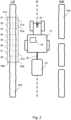
- FIG 3 schematically shows a collection of crop row volumes 91, 92, 93 as defined in accordance with an embodiment of the invention.
- the crop row volumes 91, 92, 93 cover respective portions of the left crop row LR shown in Figure 2 .
- Each crop row volume comprises a closer row of crop volumes 91a, 92a, 93a that is positioned closer to the path P than a further row of crop volumes 91b, 92b, 93b.
- Each closer and further crop row volume 91a, 92a, 93a, 91b, 92b, 93b is divided into four crop row sub-volumes I, II, III, IV.
- Each crop row sub-volume I, II, III, IV is arranged at a different height above ground.
- the vertical point density distribution of the crop row volumes 91a-93b is determined by calculating which points of the point cloud fall within each one of the crop row sub-volumes I, II, III, IV.
- the calculated vertical point density distribution of the crop row volumes 91-98 may be used by the controller 30 to detect an end of the crop row LR, RR.
- the end of a crop row may, for example, be detected when the average or maximum point density of a crop row volume 91-98 remains below a minimum threshold for a set amount of adjacent crop row volumes 91-98.
- crop rows LR, RR at both sides of the tractor are monitored and a row end is only detected when no crop 500 is found at either side of the tractor 10.
- the controller 30 may initiate a headland turn sequence that comprises controlling the implement 50 to prepare for the upcoming turn of the tractor 10 at the headland.
- the point cloud sensor 20 can be used, not just for improved implement control, but also for end of row detection. This method for end of row detection brings the advantage that it remains available in the absence of an accurate GPS signal.
- the implement 50 of the tractor 10 is a sprayer with a plurality of spraying nozzles.
- the controller 30 may be configured to control the sprayer by selectively opening and closing a subset of the plurality of spraying nozzles.
- a selectively controllable sprayer it is possible to only spray the parts of crops 500 that need to be sprayed and not waste any spraying liquid that just evaporates in the air or falls to the ground. It may further be possible to selectively spray specific amounts of spraying liquid in dependence of the local point density at the respective height, such that more spraying liquid is applied to the most dense parts of the crop.
- the implement 50 may, for example, be a duster with multiple nozzles that can be controlled individually.
- the calculated vertical point density distribution may be used to selectively control a trimmer or defoliator to operate on specific parts of trees, plants, or bushes.
Landscapes
- Engineering & Computer Science (AREA)
- Life Sciences & Earth Sciences (AREA)
- Radar, Positioning & Navigation (AREA)
- Remote Sensing (AREA)
- Environmental Sciences (AREA)
- Mechanical Engineering (AREA)
- Soil Sciences (AREA)
- Physics & Mathematics (AREA)
- General Physics & Mathematics (AREA)
- Computer Networks & Wireless Communication (AREA)
- Aviation & Aerospace Engineering (AREA)
- Automation & Control Theory (AREA)
- Insects & Arthropods (AREA)
- Pest Control & Pesticides (AREA)
- Wood Science & Technology (AREA)
- Zoology (AREA)
- Guiding Agricultural Machines (AREA)
- Control Of Position, Course, Altitude, Or Attitude Of Moving Bodies (AREA)
Abstract
Description
- The present invention relates to a method of controlling an implement of an agricultural vehicle driving over a path along a crop row. The present invention further relates to a system configured to carry out such a control method, and an agricultural vehicle comprising such a system.
- In recent years, big improvements in the accuracy of driver assistance systems have made it easier for operators of drive through the fields and make efficient use of the implements they may be pulling or pushing through these field. Partly or fully autonomous driving systems allow the driver to pay more attention to the operation of the implement. In some agricultural vehicles, visual camera systems are installed and image recognition algorithms are used for selective spraying of crops. In some newer systems, neural networks and AI processing of images may be used to classify, locate, and bound objects of interest. Other systems may use LIDAR for detecting the presence and location of trees and plants. This information may be combined with GPS information to selectively spray regions that need spraying.
- It is an aim of the present invention to further improve on the systems already disclosed in the prior art.
- According to an aspect of the invention there is provided a method of controlling an implement of an agricultural vehicle driving over a path along a crop row. The method comprises a step of using a point cloud sensor to scan a portion of the crop row and to generate a point cloud. A plurality of crop row volumes is defined. The crop row volumes are arranged along the scanned portion of the crop row. For each of the crop row volumes, a vertical point density distribution is determined by calculating which points of the point cloud fall within said crop row volume. The implement is then controlled based on the vertical point density distribution of each of the crop row volumes.
- While LIDAR may have been used before to detect the presence or absence of plants and trees, the current invention takes the use of point cloud data for implement control to another level. By determining the vertical point density in each crop row volume it is made possible to control the implement in a way that optimises the efficient use of, for example, vehicle power and spraying liquid. Instead of a one-size-fits-all approach, the now proposed control method allows for adapting the implement use to the local crop growth. For example, more spraying liquid may be used where the vegetation is more dense and more spraying liquid may be needed. In orchards, tree tops may be treated according to the local density of their foliage, without wasting energy or spraying liquid on less dense parts of the vegetation. When tilling cover crops, energy may be saved by tilling less aggressively where the crop is lower and less dense.
- In some embodiments, the LIDAR-based system may supplement a GPS-based implement control system for enhanced accuracy. The GPS-based system may, for example, make use of detailed georeferenced field maps that may have been provided by satellite imaging systems, drone observations, or previous passes of agricultural vehicles through the field. Alternatively, the LIDAR-based system is provided as a backup system for when the GPS-based implement control system fails, for example because of unreliable GPS signals.
- In a particular implementation, each of the crop row volumes comprises two or more crop row sub-volumes, each crop row sub-volume of the crop row volume being arranged at a different height above ground, and wherein the vertical point density distribution of the crop row volume is determined by calculating which points of the point cloud fall within each one of the crop row sub-volumes. The smaller the sub-volumes, the more precise the vertical point density distribution may be, and the more efficient the implement operation can be made.
- The method of controlling an implement may further comprise determining a point cloud envelope of the point cloud and controlling the implement based on the point cloud envelope. The point cloud envelope may be calculated using edge detection algorithms to determine the boundaries of the point clouds generated by the point cloud sensor. Alternatively, the point cloud envelope is determined based on the vertical point density distribution of each of the crop row volumes.
- Typically, the scanned portion of the crop row is at least partly located ahead of the implement during the scanning of said portion. The scanned portion of the crop row may be located ahead of the agricultural vehicle while the implement is located behind the agricultural vehicle.
- Typically, GPS sensors and algorithms based on GPS data are used to accurately control the timing of the use of the implement. Unfortunately, in some locations, such as inside greenhouses or in orchards with dense foliage and canopy, GPS signals may be weak and GPS-based positioning systems may not have the desired accuracy. To solve this problem, preferred embodiments of the method according to the invention further comprise a step of determining a travel speed of the agricultural vehicle and the controlling of the implement is further based on the travel speed of the agricultural vehicle. By taking into account the vehicle's travel speed, which can be done without the use of GPS, the implement's exact position relative to the observed point cloud can be determined and the timing of the use of the implement can be optimised. Travel speeds of the agricultural vehicle may, for example, be measured using odometry in the form of rotary encoders, accelerometers or camera image based motion analysis.
- In preferred embodiments, the plurality of crop row volumes may comprise a closer row of crop volumes, arranged along the scanned portion of the crop row at a first distance to the path, and a further row of crop volumes, arranged along the scanned portion of the crop row at a second distance to the path, the second distance being larger than the first distance. By also scanning the crop rows in this horizontal direction perpendicular to the travel path of the agricultural vehicle, and in addition to the calculation of a vertical point density distribution, a full 3D picture of the varying point density in the crop row can be obtained and the operation of the implement can be adapted accordingly.
- Optionally, a method according to the invention further includes a step of, based on the vertical point density distribution of the crop row volumes, detecting an end of the crop row, and a step of initiating a headland turn sequence comprising controlling the implement to prepare for an upcoming headland turn. This way, the point cloud sensor can be used, not just for improved implement control, but also for end of row detection. This method for end of row detection brings the advantage that it remains available in the absence of an accurate GPS signal. To further improve the end of row detection, the control system may look for crop row volumes with no or very few points of the generated point cloud at either side of the agricultural vehicle.
- In a particular advantageous implementation, the implement of the agricultural vehicle is a sprayer with a plurality of spraying nozzles, and controlling the implement comprises selectively opening and closing a subset of the plurality of spraying nozzles. With such a selectively controllable sprayer, it is possible to only spray the parts of crops that need to be sprayed. It may further be possible to selectively spray specific amounts of spraying liquid in dependence of the local point density at the respective height, such that more spraying liquid is applied to the most dense parts of the crop.
- The method according to the invention may further comprise the use of the point cloud sensor to scan a portion of a second crop row along another side of the path. In this case, a plurality of second crop row volumes is defined, the second crop row volumes also being arranged along the scanned portion of the second crop row. For each of the second crop row volumes, a vertical point density distribution is determined by calculating which points of the point cloud fall within said crop row volume and the implement is controlled based on the vertical point density distribution of each of the second crop row volumes. As already described above, point could data from both sides of the path may be combined to determine when the agricultural vehicle and the implement reach the end of a crop row.
- According to another aspect of the invention, a non-transitory, computer-readable storage medium is provided, storing instructions thereon that when executed by one or more processors cause the one or more processors to execute a method as described above.
- According to yet another aspect of the invention, a system is provided for controlling an implement of an agricultural vehicle driving over a path along a crop row. The system comprises a point cloud sensor configured to scan a portion of the crop row and to generate a point cloud. The point cloud sensor may, for example, be a LIDAR sensor, a stereo-camera, or a radar (e.g. Imaging or 4D radar). A controller of the system is operatively coupled to the point cloud sensor to receive the generated point cloud therefrom. The controller is configured to use the system to perform a method as described above.
- Preferably, the system further comprises a speed sensor for determining a travel speed of the agricultural vehicle. The speed sensor is operatively coupled to the controller, which is further configured to generate the control commands based on the vertical point density distribution of each of the crop row volumes and the travel speed of the agricultural vehicle. As described above, this allows the system to operate with the desired accuracy, even in situations where no reliable GPS information may be available.
- According to another aspect of the invention, an agricultural vehicle is provided. The agricultural vehicle is configured to carry and control an implement, and it comprises a control system as described above.
- Embodiments of the invention will now be described by way of example with reference to the accompanying drawings, in which:
-
Figure 1 shows a tractor that may make use of the current invention. -
Figure 2 schematically shows the tractor ofFigure 1 , towing an implement and driving between two crop rows. -
Figure 3 schematically shows a collection of crop row volumes as defined in accordance with an embodiment of the invention. -
Figure 1 shows an agricultural vehicle in the form of atractor 10 that may make use of the current invention. Apoint cloud sensor 20 is installed on the hood of thetractor 10 to scan a portion of thecrop 500 thetractor 10 drives by during use. Thepoint cloud sensor 20 may, for example, be a LIDAR sensor, a digital camera, a stereo camera, etc. Thepoint cloud sensor 20 is configured to generate a point cloud. Point clouds comprise a plurality of points with a defined position in space and thereby represent the 3D shape of an object or part of an object. The point cloud data is generally obtained by determining a distance and direction between thepoint cloud sensor 20 and a plurality of points on the surface of the object. Thepoint cloud sensor 20 in this example is installed at the hood of thetractor 10 and has a field of view that is positioned in front of thetractor 10 in the direction of travel. Thepoint cloud sensor 20 ofFigure 1 may be supplemented with, or replaced by, otherpoint cloud sensors 20 looking more to the side and/or rear of thetractor 10. Other suitable locations for installing thepoint cloud sensor 20 may, for example, include positions on or at the roof of the driver cabin or at the mount of the side mirrors. A rotatable or otherwise movablepoint cloud sensor 20 may be used to obtain a full 360° view of the direct environment of thetractor 10. - The
tractor 10 comprises a towbar, for example in the form of a three-point hitch 40, for towing an implement 50 (seeFigure 2 ). The implement 50 may be powered by the tractor engine via a PTO. In other embodiments, an implement may be carried at the tractor'sfront hitch 45. Thepoint cloud sensor 20 is coupled to acontroller 30 of thetractor 10 via a wired or wireless connection to receive the obtained point cloud data therefrom. Similarly, thecontroller 30 configured to be coupled to the implement 50, for example via a wired connection through thehitch controller 30 uses the received point cloud data to efficiently control the implement 50. Some essential and optional aspects of such methods are described below with reference toFigure 2 . -
Figure 2 schematically shows thetractor 10 ofFigure 1 , towing an implement 50 and driving over a path P between a left crop row LR and a right crop row RR. The path P may be chosen and followed by a driver steering thetractor 10 or an autonomous driving system may control thetractor 10 to follow this path P. Alternatively, the driver may steer thetractor 10 while being guided and/or assisted by a driver assistance system. The autonomous driving system or driver assistance system may, for example, use a GPS sensor to monitor the position of the tractor and adapt its course accordingly. Alternatively or additionally, the point cloud data may be used to for determining a distance between the tractor and the two crop rows LR, RR, while controlling thetractor 10 to keep both crop rows LR, RR at substantially the same distance. - According to an embodiment of the invention, the
point cloud sensor 20 is used to scan a portion of one or both crop rows LR, RR and to generate a point cloud representing the outer surface of thevegetation 500 in the respective crop row LR, RR. Depending on the crop type, the rows will contain some crop along substantially the full length of the crop row LR, RR, or gaps in between separate plants, trees, or bushes may contain no vegetation at all. The generated point cloud data is received by thecontroller 30. The controller defines a plurality of crop row volumes 91-98 that are arranged along the scanned portion of the crop row LR, RR. For each of the crop row volumes 91-98, a vertical point density distribution is determined by calculating which points of the generated point cloud fall within said crop row volume. The implement 50 is then controlled based on the vertical point density distribution of each of the crop row volumes 91-98. - Various methods are available for determining the vertical point density distribution of the crop row volumes 91-98. For example, each point in the generated point cloud may comprise a height parameter, indicating a vertical height of the point above a reference level (e.g. the ground level, or a height of the point cloud sensor 20). Based on the height parameters of all the points inside a crop row volume 91-98, a vertical point distribution can be computed using well-known mathematical algorithms. In a particular implementation, each of the crop row volumes 91-98 comprises two or more crop row sub-volumes. Each crop row sub-volume of the crop row volume 91-98 is arranged at a different height above ground. The vertical point density distribution of the crop row volume 91-98 is then determined by calculating which points of the point cloud fall within each one of the crop row sub-volumes. The smaller the sub-volumes, the more precise the vertical point density distribution will be, and the more efficient the implement operation can be made.
- While LIDAR may have been used before to detect the presence or absence of plants and trees, the current invention takes the use of point cloud data for implement control to another level. By determining the vertical point density in each crop row volume it is made possible to control the implement 50 in a way that optimises the efficient use of, for example, vehicle power and spraying liquid. Instead of a one-size-fits-all approach, the now proposed control method allows for adapting the implement use to the local crop growth. For example, more spraying liquid may be used where the
vegetation 500 is more dense and more spraying liquid may be needed. In orchards, tree tops may be treated according to the local density of their foliage, without wasting energy or spraying liquid on less dense parts of thevegetation 500. When tilling cover crops, energy may be saved by tilling less aggressively where the crop is lower and less dense. - The
controller 30 may further be used for determining a point cloud envelope of the point cloud and for controlling the implement 50 based on the point cloud envelope. A point cloud envelope may be calculated using edge detection algorithms to determine the boundaries of the point clouds generated by thepoint cloud sensor 20. Alternatively, the point cloud envelope is determined based on the vertical point density distribution of each of the crop row volumes 91-98. - Typically, the scanned portion of the crop row LR, RR is at least partly located ahead of the implement 55 during the scanning of said portion. For example, in the embodiment of
Figures 1 and2 , the scanned portion of the crop row LR, MR is located ahead of thetractor 10 while the implement 50 is located behind thetractor 50. Consequently, the implement control should normally not directly follow the point cloud data gathering. Typically, GPS sensors and algorithms based on GPS data are used to accurately control the timing of the use of the implement 50. Unfortunately, in some locations, such as inside greenhouses or in orchards with dense foliage, GPS signals may be weak and GPS-based positioning systems may not have the desired accuracy. To solve this problem, in preferred embodiments of the invention thecontroller 30 is further configured to determine a travel speed of thetractor 10 and the implement control is further based on the thus determined travel speed. By taking into account the vehicle's travel speed, the implement's exact position relative to the observed point cloud can be determined and the timing of the use of the implement 50 can be optimised. Travel speeds of thetractor 10, and the distance travelled since scanning a particular portion of the crop row LR, RR, may be measured using GPS. It may, however, be preferred to determine the travel speed in such a way that it remains accurate when no reliable GPS signal is available. For example, odometry in the form of rotary encoders, accelerometers or camera image based motion analysis may be used for accurate GPS-independent travel speed measurement. In some embodiments, the odometry system may supplement the GPS-based system for increased accuracy. In other embodiments, the odometry system is only activated when it is detected that the GPS signal is not sufficiently reliable. - In preferred embodiments, the plurality of crop row volumes 91-98 may comprise a closer row of
crop volumes 91a-98a, arranged along the scanned portion of the crop row LR, RR at a first distance to the path P, and a further row ofcrop volumes 91b-98b, arranged along the scanned portion of the crop row LR, RR at a second distance to the path P. The second distance is larger than the first distance. For not obscuringFigure 2 with too many labels, only some of the closer row ofcrop row volumes 91a-98a and further row ofcrop volumes 91b-98b have been labelled. By not just scanning the crop rows LR, RR in the vertical direction and in the direction of travel, but also in the horizontal direction perpendicular to the travel path P, a full 3D picture of the varying point density in all directions can be obtained and the operation of the implementcan 50 be adapted accordingly. -
Figure 3 schematically shows a collection ofcrop row volumes crop row volumes Figure 2 . Each crop row volume comprises a closer row ofcrop volumes crop volumes crop row volume crop row volumes 91a-93b is determined by calculating which points of the point cloud fall within each one of the crop row sub-volumes I, II, III, IV. - The calculated vertical point density distribution of the crop row volumes 91-98 may be used by the
controller 30 to detect an end of the crop row LR, RR. The end of a crop row may, for example, be detected when the average or maximum point density of a crop row volume 91-98 remains below a minimum threshold for a set amount of adjacent crop row volumes 91-98. Preferably, crop rows LR, RR at both sides of the tractor are monitored and a row end is only detected when nocrop 500 is found at either side of thetractor 10. When a row end is detected, thecontroller 30 may initiate a headland turn sequence that comprises controlling the implement 50 to prepare for the upcoming turn of thetractor 10 at the headland. This way, thepoint cloud sensor 20 can be used, not just for improved implement control, but also for end of row detection. This method for end of row detection brings the advantage that it remains available in the absence of an accurate GPS signal. - In a particular advantageous implementation, the implement 50 of the
tractor 10 is a sprayer with a plurality of spraying nozzles. Thecontroller 30 may be configured to control the sprayer by selectively opening and closing a subset of the plurality of spraying nozzles. With such a selectively controllable sprayer, it is possible to only spray the parts ofcrops 500 that need to be sprayed and not waste any spraying liquid that just evaporates in the air or falls to the ground. It may further be possible to selectively spray specific amounts of spraying liquid in dependence of the local point density at the respective height, such that more spraying liquid is applied to the most dense parts of the crop. In other embodiments, the implement 50 may, for example, be a duster with multiple nozzles that can be controlled individually. Similarly, the calculated vertical point density distribution may be used to selectively control a trimmer or defoliator to operate on specific parts of trees, plants, or bushes.
Claims (15)
- A method of controlling an implement (50) of an agricultural vehicle (10) driving over a path (P) along a crop row (LR, RR), the method comprising:using a point cloud sensor (20) to scan a portion of the crop row (LR, RR) and to generate a point cloud;defining a plurality of crop row volumes (91-98), arranged along the scanned portion of the crop row (LR, RR);for each of the crop row volumes (91-98), determining a vertical point density distribution by calculating which points of the point cloud fall within said crop row volume (91-98); andcontrolling the implement (50) based on the vertical point density distribution of each of the crop row volumes (91-98).
- A method of controlling an implement (50) as claimed in claim 1, wherein each of the crop row volumes (91-98) comprises two or more crop row sub-volumes (I, II, III, IV), each crop row sub-volume (I, II, III, IV) of the crop row volume (91-98) being arranged at a different height above ground, and wherein the vertical point density distribution of the crop row volume (91-98) is determined by calculating which points of the point cloud fall within each one of the crop row sub-volumes (I, II, III, IV).
- A method of controlling an implement (50) as claimed in claim 1 or 2, the method further comprising determining a point cloud envelope of the point cloud and controlling the implement (50) based on the point cloud envelope.
- A method of controlling an implement (50) as claimed in claim 3, wherein the point cloud envelope is determined based on the vertical point density distribution of each of the crop row volumes (91-98).
- A method of controlling an implement (50) as claimed in any preceding claim, wherein the scanned portion of the crop row (LR, RR) is at least partly located ahead of the implement (50) during the scanning of said portion, and optionally wherein the implement (50) is located behind the agricultural vehicle (10).
- A method of controlling an implement (50) as claimed in any preceding claim, further comprising determining a travel speed of the agricultural vehicle (10) and wherein the controlling the implement (50) is further based on the travel speed of the agricultural vehicle (10).
- A method of controlling an implement (50) as claimed in any preceding claim, wherein the plurality of crop row volumes (91-98) comprises a closer row of crop volumes (91a-98a), arranged along the scanned portion of the crop row (LR, RR) at a first distance to the path (P), and a further row of crop volumes (91b-98b), arranged along the scanned portion of the crop row (LR, RR) at a second distance to the path (P), the second distance being larger than the first distance.
- A method of controlling an implement (50) as claimed in any preceding claim, further comprising:based on the vertical point density distribution of the crop row volumes (91-98), detecting an end of the crop row (LR, RR); andinitiating a headland turn sequence comprising controlling the implement (50) to prepare for an upcoming headland turn.
- A method of controlling an implement (50) as claimed in any preceding claims, wherein the implement (50) is a sprayer with a plurality of spraying nozzles, and wherein controlling the implement (50) comprises selectively opening and closing a subset of the plurality of spraying nozzles.
- A method of controlling an implement (50) as claimed in any preceding claims, further comprising:using the point cloud sensor (20) to scan a portion of a second crop row (LR, RR) along another side of the path (P),defining a plurality of second crop row volumes (91-98), arranged along the scanned portion of the second crop row (LR, RR) ;for each of the second crop row volumes (91-98), determining a vertical point density distribution by calculating which points of the point cloud fall within said crop row volume (91-98); andcontrolling the implement (50) based on the vertical point density distribution of each of the second crop row volumes (91-98).
- A non-transitory, computer-readable storage medium storing instructions thereon that when executed by one or more processors cause the one or more processors to execute the method of any of claims 1 to 10.
- A system for controlling an implement of an agricultural vehicle (10) driving over a path (P) along a crop row (LR, RR), the system comprising a point cloud sensor (20) configured to scan a portion of the crop row (LR, RR) and to generate a point cloud and a controller (30), operatively coupled to the point cloud sensor to receive the generated point cloud therefrom, the controller (30) being configured todefine a plurality of crop row volumes (91-98), arranged along the scanned portion of the crop row (LR, RR);determine a vertical point density distribution for each of the crop row volumes (91-98) by calculating which points of the point cloud fall within said crop row volume (91-98); andgenerate control commands for controlling the implement (50) based on the vertical point density distribution of each of the crop row volumes (91-98).
- A system as claimed in claim 12, wherein the point cloud sensor (20) is a LIDAR sensor.
- A system as claimed in claim 12 or 13, further comprising a speed sensor for determining a travel speed of the agricultural vehicle (10), operatively coupled to the controller (30), and wherein the controller (30) is further configured to generate the control commands based on the vertical point density distribution of each of the crop row volumes (91-98) and the travel speed of the agricultural vehicle (10).
- An agricultural vehicle (10) configured to carry and control an implement (50), the agricultural vehicle (10) comprising a system as claimed in any of claims 12 to 14.
Applications Claiming Priority (1)
| Application Number | Priority Date | Filing Date | Title |
|---|---|---|---|
| IT202300025167 | 2023-11-27 |
Publications (1)
| Publication Number | Publication Date |
|---|---|
| EP4559299A1 true EP4559299A1 (en) | 2025-05-28 |
Family
ID=89722943
Family Applications (1)
| Application Number | Title | Priority Date | Filing Date |
|---|---|---|---|
| EP24215897.0A Pending EP4559299A1 (en) | 2023-11-27 | 2024-11-27 | Implement control for agricultural vehicles |
Country Status (2)
| Country | Link |
|---|---|
| US (1) | US12696832B2 (en) |
| EP (1) | EP4559299A1 (en) |
Citations (3)
| Publication number | Priority date | Publication date | Assignee | Title |
|---|---|---|---|---|
| US10151839B2 (en) * | 2012-06-01 | 2018-12-11 | Agerpoint, Inc. | Systems and methods for determining crop yields with high resolution geo-referenced sensors |
| CA3042593A1 (en) * | 2018-05-15 | 2019-11-15 | Cnh Industrial America Llc | System and method for controlling the operation of agricultural sprayers |
| CN212279614U (en) * | 2020-07-10 | 2021-01-05 | 北京农业智能装备技术研究中心 | Orchard is to target air-assisted sprayer based on laser radar |
Family Cites Families (2)
| Publication number | Priority date | Publication date | Assignee | Title |
|---|---|---|---|---|
| US12472524B2 (en) * | 2020-10-16 | 2025-11-18 | Verdant Robotics, Inc. | Fluid spraying system for targeting small objects |
| US11399531B1 (en) * | 2021-10-20 | 2022-08-02 | Verdant Robotics, Inc. | Precision detection and control of vegetation with real time pose estimation |
-
2024
- 2024-11-26 US US18/960,496 patent/US12696832B2/en active Active
- 2024-11-27 EP EP24215897.0A patent/EP4559299A1/en active Pending
Patent Citations (3)
| Publication number | Priority date | Publication date | Assignee | Title |
|---|---|---|---|---|
| US10151839B2 (en) * | 2012-06-01 | 2018-12-11 | Agerpoint, Inc. | Systems and methods for determining crop yields with high resolution geo-referenced sensors |
| CA3042593A1 (en) * | 2018-05-15 | 2019-11-15 | Cnh Industrial America Llc | System and method for controlling the operation of agricultural sprayers |
| CN212279614U (en) * | 2020-07-10 | 2021-01-05 | 北京农业智能装备技术研究中心 | Orchard is to target air-assisted sprayer based on laser radar |
Non-Patent Citations (1)
| Title |
|---|
| PENG CHEN ET AL: "GNSS-Free End-of-Row Detection and Headland Maneuvering for Orchard Navigation Using a Depth Camera", MACHINES, vol. 11, no. 1, 9 January 2023 (2023-01-09), pages 84, XP093104108, DOI: 10.3390/machines11010084 * |
Also Published As
| Publication number | Publication date |
|---|---|
| US20250280749A1 (en) | 2025-09-11 |
| US12696832B2 (en) | 2026-08-04 |
Similar Documents
| Publication | Publication Date | Title |
|---|---|---|
| US20230288936A1 (en) | Mobile machine, control unit, and method of controlling operation of a mobile machine | |
| US12365347B2 (en) | Vehicle row follow system | |
| US20170357267A1 (en) | Autonomous work vehicle obstacle detection system | |
| JP7767423B2 (en) | Row detection system, agricultural machine equipped with a row detection system, and row detection method | |
| CN108873888A (en) | agricultural system | |
| US20220132723A1 (en) | Agricultural characteristic confidence and control | |
| JP7796745B2 (en) | Crop row detection system, agricultural machine equipped with the crop row detection system, and crop row detection method | |
| EP4562987A2 (en) | Agricultural vehicles including an imaging controller, and related methods | |
| JP2024537070A (en) | Convoy Following System | |
| US20250098563A1 (en) | Work vehicle and method for controlling work vehicle | |
| JP2025002839A (en) | Row detection system and agricultural machinery | |
| WO2024135018A1 (en) | Crop row detection system and agricultural machinery | |
| JP7821820B2 (en) | agricultural machinery | |
| JP7735430B2 (en) | agricultural machinery | |
| WO2024004574A1 (en) | Work vehicle, control method and computer program | |
| US20250315058A1 (en) | Work vehicle | |
| US20250280749A1 (en) | Implement control for agricultural vehicles | |
| US20250113759A1 (en) | Work vehicle and method for controlling work vehicle | |
| WO2024135019A1 (en) | State estimation system and agriculture machine | |
| EP4562988A1 (en) | Agricultural vehicles including an imaging controller, and related methods | |
| JP7862294B2 (en) | Area recognition system and work vehicle | |
| EP4706361A1 (en) | Agricultural anomaly detection and validation systems, and related systems, methods, and agricultural vehicles | |
| US20260007087A1 (en) | Assist system for working machine and method of assisting working machine | |
| EP4706360A1 (en) | Methods of detecting temporal anomalies in agricultural fields, and related agricultural vehicles | |
| EP4706367A1 (en) | Methods of generating a map of anomalies in agricultural fields, and related agricultural vehicles |
Legal Events
| Date | Code | Title | Description |
|---|---|---|---|
| PUAI | Public reference made under article 153(3) epc to a published international application that has entered the european phase |
Free format text: ORIGINAL CODE: 0009012 |
|
| STAA | Information on the status of an ep patent application or granted ep patent |
Free format text: STATUS: THE APPLICATION HAS BEEN PUBLISHED |
|
| AK | Designated contracting states |
Kind code of ref document: A1 Designated state(s): AL AT BE BG CH CY CZ DE DK EE ES FI FR GB GR HR HU IE IS IT LI LT LU LV MC ME MK MT NL NO PL PT RO RS SE SI SK SM TR |
|
| STAA | Information on the status of an ep patent application or granted ep patent |
Free format text: STATUS: REQUEST FOR EXAMINATION WAS MADE |
|
| 17P | Request for examination filed |
Effective date: 20251128 |
|
| GRAP | Despatch of communication of intention to grant a patent |
Free format text: ORIGINAL CODE: EPIDOSNIGR1 |
|
| STAA | Information on the status of an ep patent application or granted ep patent |
Free format text: STATUS: GRANT OF PATENT IS INTENDED |
|
| INTG | Intention to grant announced |
Effective date: 20260529 |
|
| TPAC | Observations filed by third parties |
Free format text: ORIGINAL CODE: EPIDOSNTIPA |