EP4557704A1 - Method and apparatus for user plane geo redundancy with session continuity - Google Patents
Method and apparatus for user plane geo redundancy with session continuity Download PDFInfo
- Publication number
- EP4557704A1 EP4557704A1 EP24213381.7A EP24213381A EP4557704A1 EP 4557704 A1 EP4557704 A1 EP 4557704A1 EP 24213381 A EP24213381 A EP 24213381A EP 4557704 A1 EP4557704 A1 EP 4557704A1
- Authority
- EP
- European Patent Office
- Prior art keywords
- upf
- router
- gtpv1
- module
- pfcp
- Prior art date
- Legal status (The legal status is an assumption and is not a legal conclusion. Google has not performed a legal analysis and makes no representation as to the accuracy of the status listed.)
- Pending
Links
Images





Classifications
-
- H—ELECTRICITY
- H04—ELECTRIC COMMUNICATION TECHNIQUE
- H04L—TRANSMISSION OF DIGITAL INFORMATION, e.g. TELEGRAPHIC COMMUNICATION
- H04L69/00—Network arrangements, protocols or services independent of the application payload and not provided for in the other groups of this subclass
- H04L69/40—Network arrangements, protocols or services independent of the application payload and not provided for in the other groups of this subclass for recovering from a failure of a protocol instance or entity, e.g. service redundancy protocols, protocol state redundancy or protocol service redirection
-
- H—ELECTRICITY
- H04—ELECTRIC COMMUNICATION TECHNIQUE
- H04L—TRANSMISSION OF DIGITAL INFORMATION, e.g. TELEGRAPHIC COMMUNICATION
- H04L67/00—Network arrangements or protocols for supporting network services or applications
- H04L67/01—Protocols
- H04L67/10—Protocols in which an application is distributed across nodes in the network
- H04L67/1095—Replication or mirroring of data, e.g. scheduling or transport for data synchronisation between network nodes
-
- H—ELECTRICITY
- H04—ELECTRIC COMMUNICATION TECHNIQUE
- H04L—TRANSMISSION OF DIGITAL INFORMATION, e.g. TELEGRAPHIC COMMUNICATION
- H04L67/00—Network arrangements or protocols for supporting network services or applications
- H04L67/14—Session management
- H04L67/148—Migration or transfer of sessions
-
- H—ELECTRICITY
- H04—ELECTRIC COMMUNICATION TECHNIQUE
- H04W—WIRELESS COMMUNICATION NETWORKS
- H04W40/00—Communication routing or communication path finding
- H04W40/02—Communication route or path selection, e.g. power-based or shortest path routing
- H04W40/20—Communication route or path selection, e.g. power-based or shortest path routing based on geographic position or location
Definitions
- the present disclosure relates to systems and methods for radio access networks.
- the present disclosure also relates to the design of operation, administration and management of various network elements of a Fifth Generation (5G) New Radio (NR) system.
- 5G Fifth Generation
- NR New Radio
- 3GPP Technical Standards provide User Plane Function UPF session restoration procedures. These procedures for UPF failure without restart are implementation specific, and hence do not provide any guidelines for UPF failure without restart. In absence of any guidance from 3GPP Technical Standards, when the UPF fails, the UE must reconnect a session, which impacts the load of connections on all the nodes in the network, including Radio and Core network entities such as Access and Mobility Management Function (AMF) and Session Management Function (SFM). If the UPF fails and becomes active again after a finite time, an operator can select a UPF for the new and existing UE sessions. However, 3GPP Technical Standards have not defined any solution or mechanism for doing so.
- AMF Access and Mobility Management Function
- SFM Session Management Function
- a method comprising: connecting a User Plane Function (UPF) to a Session Management Function (SMF) via a PFCP-UPF router (PFCP-UPF) N4 interface; connecting a UPF Geographic Redundancy (GR) module (UPF-GR) to a Session Management Function (SMF) via a Packet Forwarding Control Protocol (PFCP) PFCP-UPF-GR router (PFCP-UPF-GR) N4 interface; connecting the UPF to a Radio via a General Packet Radio Service Tunneling Protocol (GTPv1) router (GTPv1-UPF) GTPv1 interface; connecting the UPF-GB to the Radio via a GTPv1 router-UPF-GR (GTPv1-UPF-GR) GTPv1 interface; connecting the Radio to the GTPv1-UPF router and the GTPv1-UPF-GB router via a GTPv1-Radio Router (GTPv1-Radio); connecting the SMF to the PFCP-UPF-GR
- the method can further comprise: configuring the UPF and the UPF-GR to handle a same GTPv1 Interface I Address.
- the method can further comprise configuring the UPF and the UPF-GR to handle the same IP Pool from which a UE IP is allocated.
- the method can further comprise configuring the UPF such that the BGP MED values that are installed on the UPF have higher priority than the BGP MED values at the UPF-GR so that that packets routed via the GTPv1 interface and N4 interface are routed to the UPF when both the UPF and the UPF-GR are up.
- the UPF can be configured to use anycast.
- the method can further comprise routing, via the PFCP router, a message to the available UPF configured with the higher BGP MED values; and replicating the session information at the UPF-GR at hot standby for the UPF, the SMF having an association setup with an N4 IP Address of UPF.
- the method can further comprise: routing, via the GTPV1 router, a GTPv1 message to the available UPF configured with the higher BGP MED values; routing user plane packets from Radio to the available UPF configured with the higher BGP MED values; forwarding, by the UPF the user plane packets towards a router for an N6 interface; and replicating the session information at the UPF-GR at hot standby for the UPF.
- the method can further comprise writing data to Unstructured Data Storage Function (USDF) UDSF-A on the active UPF; synching the data between UDSF-A and a UDSF-B on the UPF-GR; running a Poll Application module at the UPF-GR in the hot standby mode to recreate the sessions via a configurable timer; after an expiry of the timer expiry, recreate the available sessions available at UPF-GR via the UDSF-B; and for newly created sessions on the UPF-GR, updating the BGP configured the lower BGP MED values at an N6 interface.
- the method can further comprise, for the GTPv1 and N4 interfaces, advertising a lower BGP MED at a UPF-GR bring up.
- the method can further comprise: periodically updating the last local timestamp every time period at the UDSF-B of the active hot standby UPF-GR; converting to a local time zone and reading, by the UPF-GB, the last local timestamp; declaring the UPF-GR as active when the Poll Application in UP -GR determines that the timestamp is not updated for a preconfigured value; advertising a higher BGP MED than the one configured at UPF using a BGP update message to the PFCP router, the GTPv1 router, and the N6 interface, so that the packets are routed to UPF-GR; routing, by the PFCP router, the GTPv1 router, and the N6 router, the packets to the UPF GR.
- the method can further comprise the UPF, before marking itself active, recreating the sessions in the UDSF-A; sending a BGP Update to via PFCP-UPF router and the GTPv1_UPF router, and updating a timestamp in the UDSF-A; synchronizing the UDSF-A and the UDSF-B; reading, by the UPF-GR the timestamp after converting the timestamp to a local time zone identifying, by the UPF-GR, the UPF is up again; updating a usage and usage context back to UDSF-B by the UPF GR; synchronizing the UDSF-B and the UDSF-A; reading the information from the UDSF-A by the UPF; advertising, by the UPF, a higher BGP MED than and BGP MED published by UPF-GR using a BGP update message to the PFCP router, the GTPv1 router, and the N6 interface so that the packets are routed to this UPF; routing packets from the PFCP router
- a RAN System comprising: a User Plane Function (UPF) module; a Session Management Function (SMF) module; a PFCP-UPF router (PFCP-UPF) connecting the UPF to the SMF via an N4 interface; a UPF Geographic Redundancy (GR) module (UPF-GR) and a Packet Forwarding Control Protocol (PFCP) PFCP-UPF-GR router (PFCP-UPF-GR) connecting the UPF-GR) module (UPF-GR) to the SMF via the N4 interface; a RAN Radio node and General Packet Radio Service Tunneling Protocol (GTPv1) Radio Router (GTPv1-Radio); a UPF GTPv1 router (GTPv1-UPF) connecting the UPF to the RAN Radio node GTPv1-Radio Router via an GTPv1 interface; a UPF-GR GTPv1 router-(GTPv1-UPF-GR) connecting the UPF-GR to the RAN Radio
- the system of can comprise: the UPF module being configured such that the BGP MED values that are installed on the UPF module have higher priority than the BGP MED values at the UPF-GR module so that that packets routed via the GTPv1 interface and the N4 interface are routed to the UPF module when both the UPF module and the UPF-GR module are up.
- the UPF module can be configured to use anycast.
- the system can further comprise: the PFCP router configured to route a message to the available UPF module configured with the higher BGP MED values; and the system can be configured to replicate session information at the UPF-GR module at hot standby for the UPF module, the SMF module having an association setup with an N4 IP Address of UPF module.
- the system of can further comprise: the GTPV1 router configured to route a GTPv1 message to the available UPF module configured with the higher BGP MED values; the RAN Radio node configured to route user plane packets to the available UPF module configured with the higher BGP MED values;the UPF module configured to forward the user plane packets towards a router for an N6 interface; and the UPF-GR module configured to replicate the session information at the at hot standby for the UPF module.
- the system can further comprise: the UPF module configured to write session data to an Unstructured Data Storage Function (USDF) UDSF-A on the UPF module; a USDF on the UPF-GR (USDF-B), the system being configured to synch data between UDSF-A and the UDSF-B; the UPF-GR comprising a Poll Application module and configured to: run at the UPF-GR in the hot standby mode to recreate the sessions via a configurable timer; after an expiry of the timer expiry, recreate the available sessions available at UPF-GR via the UDSF-B; and for newly created sessions on the UPF-GR, update the BGP configured the lower BGP MED values at an N6 interface.
- USDF Unstructured Data Storage Function
- the UPF-GR module can be configured to advertise a lower BGP MED for the GTPv1 and N4 interfaces at UPF-GR bring up.
- the system can further comprise: the UPF-GR module configured to at least: periodically update the last local timestamp every time period at the UDSF-B of the active hot standby UPF-GR module; convert to a local time zone and read the last local timestamp; declare the UPF-GR module as active when the Poll Application module determines that the timestamp is not updated for a preconfigured value; and advertise a higher BGP MED than the one configured at the UPF module using a BGP update message to the PFCP router, the GTPv1 router, and the N6 interface, so that the packets are routed to UPF-GR module; whereby the PFCP router, the GTPv1 router, and the N6 router are each configured to route packets to the UPF GR until the UPF resumes an active state.
- the system can further comprise the UPF module being configured to, before marking itself active, recreating the sessions in the UDSF-A; sending a BGP Update to via PFCP-UPF router and the GTPv1_UPF router, and updating a timestamp in the UDSF-A; synchronizing the UDSF-A and the UDSF-B; reading, by the UPF-GR the timestamp after converting the timestamp to a local time zone identifying, by the UPF-GR, the UPF is up again; updating a usage and usage context back to UDSF-B by the UPF GR; synchronizing the UDSF-B and the UDSF-A; reading the information from the UDSF-A by the UPF; advertising, by the UPF, a higher BGP MED than and BGP MED published by UPF-GR using a BGP update message to the PFCP router, the GTPv1 router, and the N6 interface so that the packets are routed to this UPF; routing packets from the
- FIG. 1A is a block diagram of a system 100 for implementations as described herein.
- System 100 includes a NR UE 101, a NR gNB 106.
- the NR UE and NR gNB 106 are communicatively coupled via a Uu interface 120.
- NR UE 101 includes electronic circuitry, namely circuitry 102, that performs operations on behalf of NR UE 101 to execute methods described herein.
- Circuity 102 can be implemented with any or all of (a) discrete electronic components, (b) firmware, and (c) a programmable circuit 102A.
- NR gNB 106 includes electronic circuitry, namely circuitry 107, that performs operations on behalf of NR gNB 106 to execute methods described herein.
- Circuity 107 can be implemented with any or all of (a) discrete electronic components, (b) firmware, and (c) a programmable circuit 107A.
- Programmable circuit 107A which is an implementation of circuitry 107, includes a processor 108 and a memory 109.
- Processor 108 is an electronic device configured of logic circuitry that responds to and executes instructions.
- Memory 109 is a tangible, non-transitory, computer-readable storage device encoded with a computer program.
- memory 109 stores data and instructions, i.e., program code, that are readable and executable by processor 108 for controlling operations of processor 108.
- Memory 109 can be implemented in a random-access memory (RAM), a hard drive, a read only memory (ROM), or a combination thereof.
- One of the components of memory 109 is a program module, namely module 110.
- Module 110 includes instructions for controlling processor 108 to execute operations described herein on behalf of NR gNB 106.
- module is used herein to denote a functional operation that can be embodied either as a stand-alone component or as an integrated configuration of a plurality of subordinate components.
- each of module 105 and 110 can be implemented as a single module or as a plurality of modules that operate in cooperation with one another.
- Storage device 130 is a tangible, non-transitory, computer-readable storage device that stores module 110 thereon.
- Examples of storage device 130 include (a) a compact disk, (b) a magnetic tape, (c) a read only memory, (d) an optical storage medium, (e) a hard drive, (f) a memory unit comprising of multiple parallel hard drives, (g) a universal serial bus (USB) flash drive, (h) a random-access memory, and (i) an electronic storage device coupled to NR gNB 106 via a data communications network.
- Uu Interface (120) is the radio link between the NR UE and NR gNB, which is compliant to the 5G NR specification.
- UEs 101 can be dispersed throughout a wireless communication network, and each UE can be stationary or mobile.
- a UE includes: an access terminal, a terminal, a mobile station, a subscriber unit, a station, and the like.
- a UE can also include be a cellular phone (e.g., a smart phone), a personal digital assistant (PDA), a wireless modem, a wireless communication device, a handheld device, a laptop computer, a cordless phone, a wireless local loop (WLL) station, a tablet, a camera, a gaming device, a drone, a robot/robotic device, a netbook, a smartbook, an ultrabook, a medical device, medical equipment, a healthcare device, a biometric sensor/device, a wearable device such as a smart watch, smart clothing, smart glasses, a smart wristband, and/or smart jewelry (e.g., a smart ring, a smart bracelet, and the like), an entertainment device (e.g.,
- UEs can include UEs considered as machine-type communication (MTC) UEs or enhanced/evolved MTC (eMTC) UEs.
- MTC/eMTC UEs that can be implemented as loT UEs.
- IoT UEs include, for example, robots/robotic devices, drones, remote devices, sensors, meters, monitors, cameras, location tags, and the like, that can communicate with a BS, another device (e.g., remote device), or some other entity.
- a wireless node can provide, for example, connectivity for or to a network (e.g., a wide area network such as Internet or a cellular network) via a wired or wireless communication link.
- a network e.g., a wide area network such as Internet or a cellular network
- One or more UEs 101 in the wireless communication network can be a narrowband bandwidth UE.
- narrowband UEs devices with limited communication resources, e.g. smaller bandwidth, are considered as narrowband UEs.
- legacy devices such as legacy and/or advanced UEs, can be considered as wideband UEs.
- Wideband UEs are generally understood as devices that use greater amounts of bandwidth than narrowband UEs.
- the UEs 101 are configured to connect, for example, communicatively couple, with an or RAN.
- the RAN can be an NG RAN or a 5G RAN, an E-UTRAN, an MF RAN, or a legacy RAN, such as a UTRAN or GERAN.
- NG RAN refers to a RAN 110 that operates in an NR or 5G system
- E-UTRAN refers to a RAN that operates in an LTE or 4G system
- MF RAN refers to a RAN that operates in an MF system 100.
- the UEs 101 utilize connections (or channels), respectively, each of which comprises a physical communications interface or layer.
- the physical DL channels include the PDSCH, PMCH, PDCCH, EPDCCH, MPDCCH, R-PDCCH, SPDCCH, PBCH, PCFICH, PHICH, NPBCH, NPDCCH, NPDSCH, and/or any other physical DL channels mentioned herein.
- the physical UL channels include the PRACH, PUSCH, PUCCH, SPUCCH, NPRACH, NPUSCH, and/or any other physical UL channels mentioned herein.
- the RAN can include one or more AN nodes or RAN nodes. These access nodes can be referred to as BS, gNBs, RAN nodes, eNBs, NodeBs, RSUs, MF-APs, TRxPs or TRPs, and so forth, and comprise ground stations (e.g., terrestrial access points) or satellite stations providing coverage within a geographic area (e.g., a cell).
- NG RAN node refers to a RAN node that operates in an NR or 5G system (e.g., a gNB), and the term “E-UTRAN node” or the like refers to a RAN node that operates in an LTE or 4G system (e.g., an eNB).
- the RAN nodes can be implemented as one or more of a dedicated physical device such as a macrocell base station, and/or a low power base station for providing femtocells, picocells or other like cells having smaller coverage areas, smaller user capacity, or higher bandwidth compared to macrocells.
- all or parts of the RAN nodes can be implemented as one or more software entities running on server computers as part of a virtual network, which can be referred to as a CRAN and/or a vBBU.
- the CRAN or vBBU can implement a RAN function split, such as a PDCP split wherein RRC and PDCP layers are operated by the CRAN/vBBU and other L2 protocol entities are operated by individual RAN nodes; a MAC/PHY split where RRC, PDCP, RLC, and MAC layers are operated by the CRAN/vBBU and the PHY layer is operated by individual RAN nodes; or a "lower PHY" split where RRC, PDCP, RLC, MAC layers and upper portions of the PHY layer are operated by the CRAN/vBBU and lower portions of the PHY layer are operated by individual RAN nodes.
- a RAN function split such as a PDCP split wherein RRC and PDCP layers are operated by the CRAN/vBBU and
- an individual RAN node can represent individual gNB-DUs that are connected to a gNB-CU 151via individual F1 interfaces.
- the gNB-DUs can include one or more remote radio heads (RRH), and the gNB-CU 151can be operated by a server that is located in the RAN or by a server pool in a similar manner as the CRAN/vBBU.
- RRH remote radio heads
- One or more of the RAN nodes can be next generation eNBs (ng-eNBs), which are RAN nodes that provide E-UTRA user plane and control plane protocol terminations toward the UEs 101, and are connected to a 5GC via an NG interface.
- ng-eNBs next generation eNBs
- the MF-APs are entities that provide MultiFire radio services, and can be similar to eNBs in an 3GPP architecture.
- a scheduling entity e.g.: BS, gNB, and the like
- a scheduling entity can be configured to schedule, assign, reconfigure, and release resources for one or more subordinate entities.
- a UE 101 (or other device) can function as master node scheduling entity, scheduling resources for one or more secondary node subordinate entities (e.g., one or more other UEs 101).
- a scheduling entity and one or more subordinate entities can communicate utilizing the scheduled resources.
- the core 5G network 150 includes AMF 111, other AMFs 111, a Session Management Function (SMF) 113, and a User Plane Function (UPF) 112.
- the AMF 111 acts as a control node that processes the signaling between the UEs 101 and the core 5G network 150 to provide QoS flow and session management.
- the AMF 111 provides management for registration, connection management, reachability management, and mobility.
- UPF 112 receives a PFCP Heartbeat Request message (see 3GPP TS 29.244v16.3.1 [5]) at any time from the SMF 113 and replies with a PFCP Heartbeat Response message.
- UPF 112 maintains two Recovery Time Stamps: -
- UPF 112 After UPF 112 has restarted, it updates all local Recovery Time Stamps and clears all remote Recovery Time Stamps.
- SMF 113 information is available again, i.e.: when the PFCP Association is alive, the restarted UPF 112 sends updated Recovery Time Stamps in a Heartbeat Request message to the SMF 113 before initiating any PFCP session signaling.
- the SMF 113 on receiving Recovery Time Stamp Information Element from UPF 112, compares received remote Recovery Time Stamp value with the previous Recovery Time Stamp value stored for the UPF 112. It does the following:
- the SMF 113 If the value of a Recovery Time Stamp previously stored for this UPF is smaller than the Recovery Time Stamp value received in the Heartbeat Request or Response messages, the SMF 113 indicates that the UPF 112 has restarted. The SMF 113 then saves the new Recovery Time Stamp value for this UPF.
- SMF 113 keeps on pinging the UPF 112 using Heartbeat and keeps on logging the status the same for a preconfigured time. If UPF 112 does not comes back up within this preconfigured time, the SMF 113 can indicate that UPF has failed.
- 3GPP TS 29.244v16.3.1 [3] also provides UPF restoration procedures. A mechanism of handling restoration in accord with the Technical Standard is described below.
- the UE 101 when the UPF 112 fails, the UE 101 must reconnect the session, which impacts the load of connections on all the nodes in the network, including Radio and Core network entities such as AMF 111 and SMF 113. In case of UPF 112 failure, the UE(s) 101 that already have active sessions have to reconnect the session, which also impacts the load of connections on all the nodes in the network, including Radio and Core network entities AMF 111 and SMF 113, as a bulk of re-connects will be initiated. If the UPF 112 fails and becomes active again after a finite time (e.g.: 1 hour or more) the operator can select the UPF 112 for the new and existing UE 101 sessions.
- 3GPP Technical Standards have not defined any solution or mechanism for doing so. The present disclosure provides implementations that advantageously provide such solutions.
- FIG. 2 shows a deployment for User Plane geo-redundancy with session continuity.
- a UPF Geographic Redundancy (GR) 118 is introduced in the setup.
- a UPF 112 is connected via the Router PFCP-UPF 114 to the SMF 113 and via the Router GTPv1-UPF 116 to the RAN Radio Node 106.
- a UPF (GR) 118 is connected via the Router PFCP-UPF-GR 117 to the SMF and via the Router GTPv1-UPF-GR 119 to the RAN node 106.
- the UPF (GR) 118 is kept in a hot-standby mode.
- the UPF 112 and UPF (GR) 118 are connected via a dedicated connection (xCDR) 120 for session and state replication.
- the UPF 112 and UPF (GR) 118 are configured with same N4 IP Address.
- the SMF 113 is connected via Router (PFCP-SMF) 123 with PFCP routers of UPF 114 and UPF(GR) 117.
- the RAN node 106 is connected via Router (GTPv1-Radio) 121 with GTPv1 routers of UPF 116 and UPF(GR) 119.
- the UPF 112 and UPF(GR) 118 are configured to handle the same GTPv1 Interface IP Address.
- the UPF 112 and UPF(GR) 114 are configured to handle the same IP Pool (i.e.: IP Pool from which the UE IP are allocated).
- the BGP MED values that are installed on the UPF side have higher priority than the BGP MED values at the UPF (GR). This ensures that all packets (GTPv1 and PFCP) are routed to the UPF 112 when both UPF 112 and UPF (GR) 118 are up.
- UPF 112 and UPF-GR118 shall use anycast IP on the interfaces.
- all the N3/N4/N9/N6 interfaces can be anycast IP.
- the anycast IP address is a unique address that is assigned to interfaces.
- any peer e.g. SMF 113 or RAN node 106
- the respective router routes the request to the interface that holds that IP address.
- Anycast IP prevents UPF 112 from being in a hot standby mode as traffic is distributed to the active node. While in traditional standby setup, a node remains idle until it needs to take over when the active node fails. But, with anycast IP allocated to the interface, the same IP address is shared, and the router sends the traffic to the nearest active UPF 112.
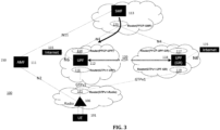
- FIG. 3 shows an example of routing of PFCP messages to UPF 112 as it has higher MED.
- the SMF 113 has an associated setup with N4 IP Address of UPF 112.
- the Router PFCP-SMF 113 routes the message to UPF 112, as it has higher MED and available. Since UPF-GR 118 site is hot standby for UPF 112, all the sessions are replicated at UPF-GR 118 site.
- the N4 Association and session information are replicated at the UPF-GR 118.
- FIG. 4 shows an example of routing of GTPv1 messages to UPF 112 as it has higher MED.
- the Router GTPV1-UPF 116 routes the user plane packets from Radio to UPF 112, as it has higher MED.
- the UPF 112 forwards the packets towards Router GTPv1-UPF 116 for the N6 interface. Since UPF-GR 118 site has hot standby for UPF 112, all the sessions are replicated at UPF-GR 118.
- FIG. 5 shows an example of Session Replication over xCDR 120.
- UPF 112 on the active site writes the data to UDSF-A 124.
- data is synched between UDSF-A 124 and UDSF-B 125.
- the UPF (GR) 118 goes to UDSF-B 125 and recreates the available sessions.
- BGP updates happen (with configured lower MED) on the N6 side.
- a lower MED advertisement happens at the UPF (GR) 118 bring up.
- the UPF (GR) 118 can be configured n to not perform data counting and measurement until it is made aware that it is active, as described below.
- FIG. 6 shows an example of Session Replication where the Hot Standby site is active.
- the UPF 112 in an active site can also be configured to periodically update the last local timestamp every time period (e.g. every 1 second), which can be preconfigured.
- the timestamp is synced in UDSF-B 125.
- the UPF (GR) 118 advertises a higher MED (than the one configured at UPF 112) using the BGP update message to routers PFCP-UPF-GR 117 and GTPV1-UPF-GR 119. BGP so that the packets are immediately routed to UPF (GR) 118. Packets (PFCP, GTPv1 and N6) then start coming to the UPF (GR) 118. The update is also sent towards the router on the internet 115 side in the Session Replication (putting the site in Hot Standby again).
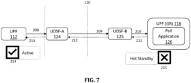
- FIG. 7 shows an example of Session Replication where the Hot Standby site placed into standby again.
- UPF 112 recreates the sessions using UDSF-A and sends BGP Update to all next hop routers it is connected to (e.g.: PFCP-SMF, GTPv1-Radio, N6) and then updates the timestamp in UDSF-A 124.
- synchronization happens between UDSF-A124 and UDSF-B 125.
- UPF (GR) 118 reads the timestamp after converting it to local time zone.
- UPF (GR) identifies that the UPF 112 is up again.
- UPF (GR) updates the usage and usage context back to UDSF-B 125.
- synchronization happens between UDSF-B and UDSF-A.
- the UPF 112 reads the information from the UDSF-A.
- the UPF 112 advertises a higher MED than the one published by UPF (GR) 118 using the BGP update message to all the routers it is connected to (e.g.: PFCP-SMF 114, GTPv1-UPF j116 --which in turn updates GTPv1-Radio 121, N6), so that the packets are immediately routed to this UPF 112. Packets (PFCP, GTPv1 and N6) then start coming to this UPF 112.
- the UPF 112 handles the traffic by reading the updated contexts.
- the UPF (GR) 118 stops the monitoring of the PDRs and instead runs a Poll Application to recreate the sessions and starts working in Hot standby again.
- An exemplary advantage from the implementations described herein is that the implementations do not introduce any changes on associate nodes in the network such as the AMF 111, SMF 112 and RAN node 106. Instead, when UPF 112 goes into redundancy, it can take care of all the procedures of session re-creation and handling. Another exemplary advantage is that these implementations handle the failure of a UPF 112 so that UE(s) 101 attached to this UPF 112 do not have to re-create the sessions, which would otherwise cause other nodes AMF 111, SMF 113 and RAN node 106 to flood with re-create requests.
- implementations and embodiments can be implemented by computer program instructions. These program instructions can be provided to a processor to produce a machine, such that the instructions, which execute on the processor, create means for implementing the actions specified herein.
- the computer program instructions can be executed by a processor to cause a series of operational steps to be performed by the processor to produce a computer-implemented process such that the instructions, which execute on the processor to provide steps for implementing the actions specified.
- some of the steps can also be performed across more than one processor, such as might arise in a multi-processor computer system or even a group of multiple computer systems.
- one or more blocks or combinations of blocks in the flowchart illustration can also be performed concurrently with other blocks or combinations of blocks, or even in a different sequence than illustrated without departing from the scope or spirit of the disclosure.
Landscapes
- Engineering & Computer Science (AREA)
- Computer Networks & Wireless Communication (AREA)
- Signal Processing (AREA)
- Computer Security & Cryptography (AREA)
- Mobile Radio Communication Systems (AREA)
Abstract
A User Plane Function UPF Geographic Redundancy (GR) and Routers on Packet Forwarding Control Protocol Router (PFCP) N4 and General Packet Radio Service Tunneling Protocol (GTPv1) interfaces for a RAN network. A UPF and UPF-GR are connected via a dedicated connection for session and state replication. The UPF-GR is kept in a hot-standby mode, and all the sessions that are created, modified, or deleted at a UPF are also created, modified, and deleted at UPF-GR. The UPF and UPF-GR are also configured with a same N4 IP Address. A Session Management Function (SMF) is connected via a PFCP Router (PFCP-SMF) with PFCP routers of UPF and UPF-GR. A RAN node is connected via a Router (GTPv1-Radio) with GTPv1 routers of UPF and UPF-GR. The UPF and UPF-GR are configured to handle the same GTPv1 Interface IP Address and the same IP Pool from which the User Equipment IPs are allocated.
Description
- The present disclosure relates to systems and methods for radio access networks. The present disclosure also relates to the design of operation, administration and management of various network elements of a Fifth Generation (5G) New Radio (NR) system.
- 3GPP Technical Standards provide User Plane Function UPF session restoration procedures. These procedures for UPF failure without restart are implementation specific, and hence do not provide any guidelines for UPF failure without restart. In absence of any guidance from 3GPP Technical Standards, when the UPF fails, the UE must reconnect a session, which impacts the load of connections on all the nodes in the network, including Radio and Core network entities such as Access and Mobility Management Function (AMF) and Session Management Function (SFM). If the UPF fails and becomes active again after a finite time, an operator can select a UPF for the new and existing UE sessions. However, 3GPP Technical Standards have not defined any solution or mechanism for doing so.
- A method comprising: connecting a User Plane Function (UPF) to a Session Management Function (SMF) via a PFCP-UPF router (PFCP-UPF) N4 interface; connecting a UPF Geographic Redundancy (GR) module (UPF-GR) to a Session Management Function (SMF) via a Packet Forwarding Control Protocol (PFCP) PFCP-UPF-GR router (PFCP-UPF-GR) N4 interface; connecting the UPF to a Radio via a General Packet Radio Service Tunneling Protocol (GTPv1) router (GTPv1-UPF) GTPv1 interface; connecting the UPF-GB to the Radio via a GTPv1 router-UPF-GR (GTPv1-UPF-GR) GTPv1 interface; connecting the Radio to the GTPv1-UPF router and the GTPv1-UPF-GB router via a GTPv1-Radio Router (GTPv1-Radio); connecting the SMF to the PFCP-UPF-GR router and the PFCP-UPF router via a PFCP-SMF router (PFCP-SMF); connecting the UPF and the UPF GR via a dedicated connection for session and state replication; and maintaining the UPF-GR in a hot-standby mode so that sessions at the UPF are also replicated at the UPF-GR. The method can further comprise: configuring the UPF and the UPF-GR to handle a same GTPv1 Interface I Address. The method can further comprise configuring the UPF and the UPF-GR to handle the same IP Pool from which a UE IP is allocated. The method can further comprise configuring the UPF such that the BGP MED values that are installed on the UPF have higher priority than the BGP MED values at the UPF-GR so that that packets routed via the GTPv1 interface and N4 interface are routed to the UPF when both the UPF and the UPF-GR are up. The UPF can be configured to use anycast. The method can further comprise routing, via the PFCP router, a message to the available UPF configured with the higher BGP MED values; and replicating the session information at the UPF-GR at hot standby for the UPF, the SMF having an association setup with an N4 IP Address of UPF. The method can further comprise: routing, via the GTPV1 router, a GTPv1 message to the available UPF configured with the higher BGP MED values; routing user plane packets from Radio to the available UPF configured with the higher BGP MED values; forwarding, by the UPF the user plane packets towards a router for an N6 interface; and replicating the session information at the UPF-GR at hot standby for the UPF.
- In an implementation, the method can further comprise writing data to Unstructured Data Storage Function (USDF) UDSF-A on the active UPF; synching the data between UDSF-A and a UDSF-B on the UPF-GR; running a Poll Application module at the UPF-GR in the hot standby mode to recreate the sessions via a configurable timer; after an expiry of the timer expiry, recreate the available sessions available at UPF-GR via the UDSF-B; and for newly created sessions on the UPF-GR, updating the BGP configured the lower BGP MED values at an N6 interface. The method can further comprise, for the GTPv1 and N4 interfaces, advertising a lower BGP MED at a UPF-GR bring up. The method can further comprise: periodically updating the last local timestamp every time period at the UDSF-B of the active hot standby UPF-GR; converting to a local time zone and reading, by the UPF-GB, the last local timestamp; declaring the UPF-GR as active when the Poll Application in UP -GR determines that the timestamp is not updated for a preconfigured value; advertising a higher BGP MED than the one configured at UPF using a BGP update message to the PFCP router, the GTPv1 router, and the N6 interface, so that the packets are routed to UPF-GR; routing, by the PFCP router, the GTPv1 router, and the N6 router, the packets to the UPF GR. The method can further comprise the UPF, before marking itself active, recreating the sessions in the UDSF-A; sending a BGP Update to via PFCP-UPF router and the GTPv1_UPF router, and updating a timestamp in the UDSF-A; synchronizing the UDSF-A and the UDSF-B; reading, by the UPF-GR the timestamp after converting the timestamp to a local time zone identifying, by the UPF-GR, the UPF is up again; updating a usage and usage context back to UDSF-B by the UPF GR; synchronizing the UDSF-B and the UDSF-A; reading the information from the UDSF-A by the UPF; advertising, by the UPF, a higher BGP MED than and BGP MED published by UPF-GR using a BGP update message to the PFCP router, the GTPv1 router, and the N6 interface so that the packets are routed to this UPF; routing packets from the PFCP router, the GTPv1 router, and the N6 interface to the UPF; handling the packets by the UPF by reading the updated usage context; running, by the UPF-GR, the Poll Application to recreate the sessions and resuming a hot standby state, wherein the UPF GR stops the monitoring of the PDRs.
- In an implementation, disclosed is a RAN System comprising: a User Plane Function (UPF) module; a Session Management Function (SMF) module; a PFCP-UPF router (PFCP-UPF) connecting the UPF to the SMF via an N4 interface; a UPF Geographic Redundancy (GR) module (UPF-GR) and a Packet Forwarding Control Protocol (PFCP) PFCP-UPF-GR router (PFCP-UPF-GR) connecting the UPF-GR) module (UPF-GR) to the SMF via the N4 interface; a RAN Radio node and General Packet Radio Service Tunneling Protocol (GTPv1) Radio Router (GTPv1-Radio); a UPF GTPv1 router (GTPv1-UPF) connecting the UPF to the RAN Radio node GTPv1-Radio Router via an GTPv1 interface; a UPF-GR GTPv1 router-(GTPv1-UPF-GR) connecting the UPF-GR to the RAN Radio node GTPv1-Radio Router via the GTPv1 interface; a PFCP-SMF router (PFCP-SMF) connecting the SMF to the PFCP-UPF-GR router and the PFCP-UPF router via the N4 interface; and a dedicated connection connecting the UPF module and the UPF GR module for session and state replication, wherein the UPF-GR module is configured to be in a hot-standby mode so that sessions at the UPF module are also replicated at the UPF-GR module. The system can comprise: the UPF module and the UPF-GR module each being configured to handle a same GTPv1 Interface IP Address and each being configured to handle a same IP Pool.
- In an implementation, the system of can comprise: the UPF module being configured such that the BGP MED values that are installed on the UPF module have higher priority than the BGP MED values at the UPF-GR module so that that packets routed via the GTPv1 interface and the N4 interface are routed to the UPF module when both the UPF module and the UPF-GR module are up. The UPF module can be configured to use anycast. The system can further comprise: the PFCP router configured to route a message to the available UPF module configured with the higher BGP MED values; and the system can be configured to replicate session information at the UPF-GR module at hot standby for the UPF module, the SMF module having an association setup with an N4 IP Address of UPF module. The system of can further comprise: the GTPV1 router configured to route a GTPv1 message to the available UPF module configured with the higher BGP MED values; the RAN Radio node configured to route user plane packets to the available UPF module configured with the higher BGP MED values;the UPF module configured to forward the user plane packets towards a router for an N6 interface; and the UPF-GR module configured to replicate the session information at the at hot standby for the UPF module.
- The system can further comprise: the UPF module configured to write session data to an Unstructured Data Storage Function (USDF) UDSF-A on the UPF module; a USDF on the UPF-GR (USDF-B), the system being configured to synch data between UDSF-A and the UDSF-B; the UPF-GR comprising a Poll Application module and configured to: run at the UPF-GR in the hot standby mode to recreate the sessions via a configurable timer; after an expiry of the timer expiry, recreate the available sessions available at UPF-GR via the UDSF-B; and for newly created sessions on the UPF-GR, update the BGP configured the lower BGP MED values at an N6 interface. The UPF-GR module can be configured to advertise a lower BGP MED for the GTPv1 and N4 interfaces at UPF-GR bring up. The system can further comprise: the UPF-GR module configured to at least: periodically update the last local timestamp every time period at the UDSF-B of the active hot standby UPF-GR module; convert to a local time zone and read the last local timestamp; declare the UPF-GR module as active when the Poll Application module determines that the timestamp is not updated for a preconfigured value; and advertise a higher BGP MED than the one configured at the UPF module using a BGP update message to the PFCP router, the GTPv1 router, and the N6 interface, so that the packets are routed to UPF-GR module; whereby the PFCP router, the GTPv1 router, and the N6 router are each configured to route packets to the UPF GR until the UPF resumes an active state.
- The system can further comprise the UPF module being configured to, before marking itself active, recreating the sessions in the UDSF-A; sending a BGP Update to via PFCP-UPF router and the GTPv1_UPF router, and updating a timestamp in the UDSF-A; synchronizing the UDSF-A and the UDSF-B; reading, by the UPF-GR the timestamp after converting the timestamp to a local time zone identifying, by the UPF-GR, the UPF is up again; updating a usage and usage context back to UDSF-B by the UPF GR; synchronizing the UDSF-B and the UDSF-A; reading the information from the UDSF-A by the UPF; advertising, by the UPF, a higher BGP MED than and BGP MED published by UPF-GR using a BGP update message to the PFCP router, the GTPv1 router, and the N6 interface so that the packets are routed to this UPF; routing packets from the PFCP router, the GTPv1 router, and the N6 interface to the UPF; handling the packets by the UPF by reading the updated usage context; and the UPF-GR being configured to run the Poll Application to recreate the sessions and resuming a hot standby state, wherein the UPF GR stops the monitoring of the PDRs.
- Non-limiting and non-exhaustive embodiments are described with reference to the following drawings. In the drawings, like reference numerals refer to like parts throughout the various figures unless otherwise specified. For a better understanding, reference can be configured to be made to the following Detailed Description, which is to be read in association with the accompanying drawings.
- Various embodiments and implementations now will be described more fully hereinafter with reference to the accompanying drawings, which form a part hereof, and which show, by way of illustration, specific embodiments by which the innovations described herein can be practiced. The embodiments can, however, be embodied in many different forms and should not be construed as limited to the embodiments and implementations set forth herein; rather, these embodiments and implementations are provided so that this disclosure will be thorough and complete, and will fully convey the scope of the embodiments and implementations to those skilled in the art. Among other things, the various embodiments and implementations can be methods, systems, media, or devices. The following detailed description is, therefore, not to be taken in a limiting sense.
- Throughout the specification and claims, the following terms take the meanings explicitly associated herein, unless the context clearly dictates otherwise. The term "herein" refers to the specification, claims, and drawings associated with the current application.
- In addition, as used herein, the term "or" is an inclusive "or" operator, and is equivalent to the term "and/or," unless the context clearly dictates otherwise. The term "based on" is not exclusive and allows for being based on additional factors not described, unless the context clearly dictates otherwise. In addition, throughout the specification, the meaning of "a," "an," and "the" include plural references. The meaning of "in" includes "in" and "on."
-
FIG. 1A shows a network architecture. -
FIG. 1B shows a network architecture. -
FIG. 1C shows a network architecture. -
FIG. 1D shows a network architecture. -
FIG. 2 shows implementation of a network architecture and flow. -
FIG. 3 shows an implementation of a network architecture and flow. -
FIG. 1 . shows an implementation of a network architecture and flow. -
FIG. 5 shows an implementation of a network architecture and flow. -
FIG. 6 shows an implementation of a network architecture and flow. -
FIG. 7 shows an implementation of a network architecture and flow. - Reference is made to Third Generation Partnership Project (3GPP) and the Internet Engineering Task Force (IETF) in accordance with embodiments of the present disclosure. The present disclosure employs abbreviations, terms and technology defined in accord with Third Generation Partnership Project (3GPP) and/or Internet Engineering Task Force (IETF) technology standards and papers, including the following standards and definitions. 3GPP and IETF technical specifications (TS), standards (including proposed standards), technical reports (TR) and other papers are incorporated by reference in their entirety hereby, define the related terms and architecture reference models that follow.
-
- 3GPP 3rd Generation Partnership Project
- 5G 5th Generation
- 5GC 5G Core Network
- 5GS 5G System
- AMF Access and Mobility Management Function
- BGP Border Gateway Protocol
- CP Control Plane
- E-UTRAN: Evolved Universal Terrestrial Radio Access Network
- GTP GPRS Tunneling Protocol
- gNB: gNodeB (5G base station)
- GPRS General packet radio service
- SMF Session Management Function
- MED Multi Exit Discriminator
- PFCP Packet Forwarding Control Protocol
- UE: User Equipment
- UDSF Unstructured Data Storage Function
- UP User Plane
- UPF User Plane Function
- xCDR eXtended Cross Datacenter Replication
-
- [1] 3GPP TS 23.501v18.3.0: "System Architecture for the 5G System", (2023-09-19)
- [2] 3GPP TS 23.502v18.3.0:"Procedures for the 5G System", (2023-09-19)
- [3] 3GPP TS 23.527 v18.1.0: "5G System, Restoration procedures", (20223-09-19)
- [4] 3GPP TS 23 007 v18.2.1: "LTE, Restoration procedures", (2023-06-29)
- [5] 3GPP TS 29.244v18.3.1:" Interface between the Control Plane and the User Plane Nodes ", (2023-09-20);
- [6] 3GPP TS 38.401 v17.6.1: "NG-RAN; Architecture description", (2023-09-22)
- [7] (3GPP TS 38.300 17.10.0 "NR; NR and NG-RAN Overall description; Stage-2", (2023-09-27)
-
FIG. 1A is a block diagram of asystem 100 for implementations as described herein.System 100 includes aNR UE 101, aNR gNB 106. The NR UE andNR gNB 106 are communicatively coupled via aUu interface 120. -
NR UE 101 includes electronic circuitry, namelycircuitry 102, that performs operations on behalf ofNR UE 101 to execute methods described herein.Circuity 102 can be implemented with any or all of (a) discrete electronic components, (b) firmware, and (c) aprogrammable circuit 102A. -
NR gNB 106 includes electronic circuitry, namelycircuitry 107, that performs operations on behalf ofNR gNB 106 to execute methods described herein.Circuity 107 can be implemented with any or all of (a) discrete electronic components, (b) firmware, and (c) aprogrammable circuit 107A. -
Programmable circuit 107A, which is an implementation ofcircuitry 107, includes a processor 108 and amemory 109. Processor 108 is an electronic device configured of logic circuitry that responds to and executes instructions.Memory 109 is a tangible, non-transitory, computer-readable storage device encoded with a computer program. In this regard,memory 109 stores data and instructions, i.e., program code, that are readable and executable by processor 108 for controlling operations of processor 108.Memory 109 can be implemented in a random-access memory (RAM), a hard drive, a read only memory (ROM), or a combination thereof. One of the components ofmemory 109 is a program module, namelymodule 110.Module 110 includes instructions for controlling processor 108 to execute operations described herein on behalf ofNR gNB 106. - The term "module" is used herein to denote a functional operation that can be embodied either as a stand-alone component or as an integrated configuration of a plurality of subordinate components. Thus, each of
module - While
modules 110 are indicated as being already loaded intomemories 109, andmodule 110 can be configured on astorage device 130 for subsequent loading into theirmemories 109.Storage device 130 is a tangible, non-transitory, computer-readable storage device that storesmodule 110 thereon. Examples ofstorage device 130 include (a) a compact disk, (b) a magnetic tape, (c) a read only memory, (d) an optical storage medium, (e) a hard drive, (f) a memory unit comprising of multiple parallel hard drives, (g) a universal serial bus (USB) flash drive, (h) a random-access memory, and (i) an electronic storage device coupled toNR gNB 106 via a data communications network. - Uu Interface (120) is the radio link between the NR UE and NR gNB, which is compliant to the 5G NR specification.
-
UEs 101 can be dispersed throughout a wireless communication network, and each UE can be stationary or mobile. A UE includes: an access terminal, a terminal, a mobile station, a subscriber unit, a station, and the like. A UE can also include be a cellular phone (e.g., a smart phone), a personal digital assistant (PDA), a wireless modem, a wireless communication device, a handheld device, a laptop computer, a cordless phone, a wireless local loop (WLL) station, a tablet, a camera, a gaming device, a drone, a robot/robotic device, a netbook, a smartbook, an ultrabook, a medical device, medical equipment, a healthcare device, a biometric sensor/device, a wearable device such as a smart watch, smart clothing, smart glasses, a smart wristband, and/or smart jewelry (e.g., a smart ring, a smart bracelet, and the like), an entertainment device (e.g., a music device, a video device, a satellite radio, and the like), industrial manufacturing equipment, a global positioning system (GPS) device, or any other suitable device configured to communicate via a wireless or wired medium. UEs can include UEs considered as machine-type communication (MTC) UEs or enhanced/evolved MTC (eMTC) UEs. MTC/eMTC UEs that can be implemented as loT UEs. IoT UEs include, for example, robots/robotic devices, drones, remote devices, sensors, meters, monitors, cameras, location tags, and the like, that can communicate with a BS, another device (e.g., remote device), or some other entity. A wireless node can provide, for example, connectivity for or to a network (e.g., a wide area network such as Internet or a cellular network) via a wired or wireless communication link. - One or
more UEs 101 in the wireless communication network can be a narrowband bandwidth UE. As used herein, devices with limited communication resources, e.g. smaller bandwidth, are considered as narrowband UEs. Similarly, legacy devices, such as legacy and/or advanced UEs, can be considered as wideband UEs. Wideband UEs are generally understood as devices that use greater amounts of bandwidth than narrowband UEs. - The
UEs 101 are configured to connect, for example, communicatively couple, with an or RAN. In embodiments, the RAN can be an NG RAN or a 5G RAN, an E-UTRAN, an MF RAN, or a legacy RAN, such as a UTRAN or GERAN. The term "NG RAN" or the like refers to aRAN 110 that operates in an NR or 5G system, the term "E-UTRAN" or the like refers to a RAN that operates in an LTE or 4G system, and the term "MF RAN" or the like refers to a RAN that operates in anMF system 100. TheUEs 101 utilize connections (or channels), respectively, each of which comprises a physical communications interface or layer. The connections and can comprise several different physical DL channels and several different physical UL channels. As examples, the physical DL channels include the PDSCH, PMCH, PDCCH, EPDCCH, MPDCCH, R-PDCCH, SPDCCH, PBCH, PCFICH, PHICH, NPBCH, NPDCCH, NPDSCH, and/or any other physical DL channels mentioned herein. As examples, the physical UL channels include the PRACH, PUSCH, PUCCH, SPUCCH, NPRACH, NPUSCH, and/or any other physical UL channels mentioned herein. - The RAN can include one or more AN nodes or RAN nodes. These access nodes can be referred to as BS, gNBs, RAN nodes, eNBs, NodeBs, RSUs, MF-APs, TRxPs or TRPs, and so forth, and comprise ground stations (e.g., terrestrial access points) or satellite stations providing coverage within a geographic area (e.g., a cell). The term "NG RAN node" or the like refers to a RAN node that operates in an NR or 5G system (e.g., a gNB), and the term "E-UTRAN node" or the like refers to a RAN node that operates in an LTE or 4G system (e.g., an eNB). According to various embodiments, the RAN nodes can be implemented as one or more of a dedicated physical device such as a macrocell base station, and/or a low power base station for providing femtocells, picocells or other like cells having smaller coverage areas, smaller user capacity, or higher bandwidth compared to macrocells.
- In some embodiments, all or parts of the RAN nodes can be implemented as one or more software entities running on server computers as part of a virtual network, which can be referred to as a CRAN and/or a vBBU. In these embodiments, the CRAN or vBBU can implement a RAN function split, such as a PDCP split wherein RRC and PDCP layers are operated by the CRAN/vBBU and other L2 protocol entities are operated by individual RAN nodes; a MAC/PHY split where RRC, PDCP, RLC, and MAC layers are operated by the CRAN/vBBU and the PHY layer is operated by individual RAN nodes; or a "lower PHY" split where RRC, PDCP, RLC, MAC layers and upper portions of the PHY layer are operated by the CRAN/vBBU and lower portions of the PHY layer are operated by individual RAN nodes. This virtualized framework allows the freed-up processor cores of the RAN nodes to perform other virtualized applications. In some implementations, an individual RAN node can represent individual gNB-DUs that are connected to a gNB-CU 151via individual F1 interfaces. In these implementations, the gNB-DUs can include one or more remote radio heads (RRH), and the gNB-CU 151can be operated by a server that is located in the RAN or by a server pool in a similar manner as the CRAN/vBBU. One or more of the RAN nodes can be next generation eNBs (ng-eNBs), which are RAN nodes that provide E-UTRA user plane and control plane protocol terminations toward the
UEs 101, and are connected to a 5GC via an NG interface. In MF implementations, the MF-APs are entities that provide MultiFire radio services, and can be similar to eNBs in an 3GPP architecture. - In some implementations, access to a wireless interface can be scheduled, wherein a scheduling entity (e.g.: BS, gNB, and the like) allocates bandwidth resources for devices and equipment in its service area or cell. As scheduling entity can be configured to schedule, assign, reconfigure, and release resources for one or more subordinate entities. In some examples, a UE 101 (or other device) can function as master node scheduling entity, scheduling resources for one or more secondary node subordinate entities (e.g., one or more other UEs 101). Thus, in a wireless communication network with a scheduled access to time-frequency resources and having a cellular configuration, a P2P configuration, and a mesh configuration, a scheduling entity and one or more subordinate entities can communicate utilizing the scheduled resources.
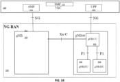
- An NG-RAN (NG-Radio Access Network) architecture from 3GPP TS 38.401 [6] is described below with respect to
FIG. 1B . F1 is the interface between gNB-CU 151 (gNB - Centralized Unit) and gNB-DU 152 (gNB - Distributed Unit), NG is the interface between gNB-CU 151 (or gNB) and 5GC (5G Core), E1 is the interface between CU-CP (CU-Control Plane) and CU-UP (CU-User Plane), and Xn is interface between gNBs. - An E-UTRAN architecture is illustrated in
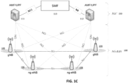
Fig. 1C . E-UTRAN that supports an NG-RAN architecture. An exemplary NG-RAN Radio node 106 is either: a gNB, providing NR user plane and control plane protocol terminations towards the UE; or an ng-eNB, providing E-UTRA user plane and control plane protocol terminations towards the UE. ([7] 3GPP TS 38.300 17.3.0.) As shown inFigure 1C , the gNBs and ng-eNBs are interconnected with each other by means of the Xn interface. - In
Figs. 1B-1C , the NG-RAN Radio Node (e.g.: gNBs and/or ng-eNBs) are also connected by means of the NG interfaces to the 5GC, more specifically to the AMF (Access and Mobility Management Function) by means of the NG-C interface and to the UPF (User Plane Function) by means of the NG-U interface. The gNB and ng-eNB host functions for Radio Resource Management such as: Radio Bearer Control, Radio Admission Control, Connection Mobility Control, Dynamic allocation of resources to UEs in both uplink and downlink (scheduling), connection setup and release; session Management; QoS Flow management and mapping to data radio bearers. - 3GPP TS 23.501v16.2.0 [1] and 3GPP TS 23.502v16.2.0 [2] have defined a network architecture where a UPF is connected as a core network to transfer the user plane packets sent or to be received by UE.
FIG. 1D shows an exemplary network architecture in accord with these Technical Standards. - The
core 5G network 150 includesAMF 111,other AMFs 111, a Session Management Function (SMF) 113, and a User Plane Function (UPF) 112. TheAMF 111 acts as a control node that processes the signaling between theUEs 101 and thecore 5G network 150 to provide QoS flow and session management. For example, theAMF 111 provides management for registration, connection management, reachability management, and mobility. -
SMF 113 provides Session Management such as session establishment, modification and release, tunnel maintenance betweenUPF 112 andRAN node 106, UE IP address allocation and management, and traffic steering atUPF 112 to route traffic to proper destination. - User Internet protocol (IP) packets are transferred through the
UPF 112. TheUPF 112 provides UE IP address allocation, packet routing and forwarding, packet inspection, QoS handling for user plane, as well as other functions. TheUPF 112 is connected to theIP Services 115 such as Internet, an intranet, an IP Multimedia Subsystem (IMS), a PS Streaming Service, and/or other IP services. - For
UPF 112 communications, two restoration mechanisms are required: one due to restart ofUPF 112 node and another due toUPF 112 failure. The difference between restart and failure is that in restart,UPF 112 is expected to come up within a predefined finite time. However, in case of failure, theUPF 112 may not come up at all or may come up in an undefined time. - 3GPP TS 23.527 v16.4.0 [3] defines procedures where
SMF 113 can detectUPF 112 restart and initiate recovery procedures. However, forUPF 112 failure scenarios, no new procedures are defined, and this is left to implementing providers. - Accordingly described are procedures for session continuity with geographical redundancy for the
UPF 112 failure scenarios. - 3GPP TS 23.527 v16.4.0 [3] and 3GPP TS 23.007 v17.4.1 [4] have defined a procedure to detect the
UPF 112 restart. The below section defines the handling as per these 3GPP Technical Standards. The reference node for the interface used betweenSMF 113 andUPF 112 is PFCP N4 interface. On the N4 interface, SMF 1113 utilizes PFCP Heartbeat Request and Heartbeat Response messages to detectUPF 113 failure or restart. -
UPF 112 receives a PFCP Heartbeat Request message (see 3GPP TS 29.244v16.3.1 [5]) at any time from theSMF 113 and replies with a PFCP Heartbeat Response message. Here,UPF 112 maintains two Recovery Time Stamps: - - a remote Recovery Time Stamp of
SMF 113, that it has received during the association procedures; and - a local recovery Time Stamp that was sent to
SMF 113 during association procedures. - After
UPF 112 has restarted, it updates all local Recovery Time Stamps and clears all remote Recovery Time Stamps. WhenSMF 113 information is available again, i.e.: when the PFCP Association is alive, the restartedUPF 112 sends updated Recovery Time Stamps in a Heartbeat Request message to theSMF 113 before initiating any PFCP session signaling. - The
SMF 113, on receiving Recovery Time Stamp Information Element fromUPF 112, compares received remote Recovery Time Stamp value with the previous Recovery Time Stamp value stored for theUPF 112. It does the following: - If no previous value was stored, the Recovery Time Stamp value received in the Heartbeat Request or Response messages is stored for this
UPF 112. - If the value of a Recovery Time Stamp previously stored for this UPF is smaller than the Recovery Time Stamp value received in the Heartbeat Request or Response messages, the
SMF 113 indicates that theUPF 112 has restarted. TheSMF 113 then saves the new Recovery Time Stamp value for this UPF. - If the value of a Recovery Time Stamp previously stored for this
UPF 112 is larger than the Recovery Time Stamp value received in the Heartbeat Request, or Response message indicates a possible race condition (i.e.: a newer message has come before the older message),SMF 113 ignores the received new Recovery Time Stamp value. - For
UPF 112 failure,SMF 113 keeps on pinging theUPF 112 using Heartbeat and keeps on logging the status the same for a preconfigured time. IfUPF 112 does not comes back up within this preconfigured time, theSMF 113 can indicate that UPF has failed. - 3GPP TS 29.244v16.3.1 [3] also provides UPF restoration procedures. A mechanism of handling restoration in accord with the Technical Standard is described below.
- Restart Case: here, after restart of
UPF 112, in accord with 3GPP, the PFCP association between the SMF(s) 113 and theUPF 112 must be re-established. Once the association is reestablished, restoration of the PFCP sessions is started immediately in Proactive and Reactive modes: - In Proactive mode, the restoration is initiated by
SMF 113, where it starts reestablishing PFCP sessions matching any PDRs. - In Reactive mode, the restoration is initiated by
SMF 113, where it initiates a message to establish PFCP session with a wildcarded PDR to instruct theUPF 112 to forward G-PDU packets that are not matching any other PDRs. - As noted herein, in the absence of any guidance from 3GPP Technical Standards, when the
UPF 112 fails, theUE 101 must reconnect the session, which impacts the load of connections on all the nodes in the network, including Radio and Core network entities such asAMF 111 andSMF 113. In case ofUPF 112 failure, the UE(s) 101 that already have active sessions have to reconnect the session, which also impacts the load of connections on all the nodes in the network, including Radio and Corenetwork entities AMF 111 andSMF 113, as a bulk of re-connects will be initiated. If theUPF 112 fails and becomes active again after a finite time (e.g.: 1 hour or more) the operator can select theUPF 112 for the new and existingUE 101 sessions. However, 3GPP Technical Standards have not defined any solution or mechanism for doing so. The present disclosure provides implementations that advantageously provide such solutions. - In an implementation,
FIG. 2 : shows a deployment for User Plane geo-redundancy with session continuity. - As part of the setup, available routers on PFCP N4 and GTPv1 sides are introduced in the network. A UPF Geographic Redundancy (GR) 118 is introduced in the setup. A
UPF 112 is connected via the Router PFCP-UPF 114 to theSMF 113 and via the Router GTPv1-UPF 116 to theRAN Radio Node 106. A UPF (GR) 118 is connected via the Router PFCP-UPF-GR 117 to the SMF and via the Router GTPv1-UPF-GR 119 to theRAN node 106. The UPF (GR) 118 is kept in a hot-standby mode. This means all the sessions that are created, modified, or deleted at theUPF 112 are also created, modified, and deleted at UPF (GR) 118. TheUPF 112 and UPF (GR) 118 are connected via a dedicated connection (xCDR) 120 for session and state replication. TheUPF 112 and UPF (GR) 118 are configured with same N4 IP Address. TheSMF 113 is connected via Router (PFCP-SMF) 123 with PFCP routers ofUPF 114 and UPF(GR) 117. TheRAN node 106 is connected via Router (GTPv1-Radio) 121 with GTPv1 routers ofUPF 116 and UPF(GR) 119. TheUPF 112 and UPF(GR) 118 are configured to handle the same GTPv1 Interface IP Address. TheUPF 112 and UPF(GR) 114 are configured to handle the same IP Pool (i.e.: IP Pool from which the UE IP are allocated). - The BGP MED values that are installed on the UPF side have higher priority than the BGP MED values at the UPF (GR). This ensures that all packets (GTPv1 and PFCP) are routed to the
UPF 112 when bothUPF 112 and UPF (GR) 118 are up. -
UPF 112 and UPF-GR118 shall use anycast IP on the interfaces. Using anycast IP, all the N3/N4/N9/N6 interfaces can be anycast IP. The anycast IP address is a unique address that is assigned to interfaces. As such, when any peer (e.g. SMF 113 or RAN node 106) sends a request to an anycast IP address, the respective router routes the request to the interface that holds that IP address. Anycast IP preventsUPF 112 from being in a hot standby mode as traffic is distributed to the active node. While in traditional standby setup, a node remains idle until it needs to take over when the active node fails. But, with anycast IP allocated to the interface, the same IP address is shared, and the router sends the traffic to the nearestactive UPF 112. - In an implementation,
FIG. 3 shows an example of routing of PFCP messages toUPF 112 as it has higher MED. TheSMF 113 has an associated setup with N4 IP Address ofUPF 112. The Router PFCP-SMF 113 routes the message toUPF 112, as it has higher MED and available. Since UPF-GR 118 site is hot standby forUPF 112, all the sessions are replicated at UPF-GR 118 site. The N4 Association and session information are replicated at the UPF-GR 118. - In an implementation,
FIG. 4 shows an example of routing of GTPv1 messages toUPF 112 as it has higher MED. The Router GTPV1-UPF 116 routes the user plane packets from Radio toUPF 112, as it has higher MED. TheUPF 112 forwards the packets towards Router GTPv1-UPF 116 for the N6 interface. Since UPF-GR 118 site has hot standby forUPF 112, all the sessions are replicated at UPF-GR 118. - In an implementation,
FIG. 5 shows an example of Session Replication overxCDR 120. As shown inFIG. 5 , at 202UPF 112 on the active site writes the data to UDSF-A 124. At 203 data is synched between UDSF-A 124 and UDSF-B 125.t 204, the UPF (GR) 118 in a hot standby mode, runs aPoll Application 126 to recreate the sessions (via a configurable timer=Default 1 minute). After every timer expiry, the UPF (GR) 118 goes to UDSF-B 125 and recreates the available sessions. For newly created sessions on the UPF (GR) 118, BGP updates happen (with configured lower MED) on the N6 side. For the GTPv1 and N4 interfaces, a lower MED advertisement happens at the UPF (GR) 118 bring up. The UPF (GR) 118 can be configured n to not perform data counting and measurement until it is made aware that it is active, as described below. - In an implementation,
FIG. 6 shows an example of Session Replication where the Hot Standby site is active. As shown at 205, theUPF 112 in an active site can also be configured to periodically update the last local timestamp every time period (e.g. every 1 second), which can be preconfigured. At 206, the timestamp is synced in UDSF-B 125. At 207 the UPF (GR) 118 reads the timestamp after converting it to a local time zone. If thePoll Application 126 in UPF (GR) 118 determines that the timestamp is not updated for the configured value (default=5 sec), at 208 the UPF (GR) 118 declares itself as active and ready to handle the traffic. The UPF (GR) 118 advertises a higher MED (than the one configured at UPF 112) using the BGP update message to routers PFCP-UPF-GR 117 and GTPV1-UPF-GR 119. BGP so that the packets are immediately routed to UPF (GR) 118. Packets (PFCP, GTPv1 and N6) then start coming to the UPF (GR) 118. The update is also sent towards the router on theinternet 115 side in the Session Replication (putting the site in Hot Standby again). - In an implementation,
FIG. 7 shows an example of Session Replication where the Hot Standby site placed into standby again. Before marking itself active in UDSF-A 124, at 208UPF 112 recreates the sessions using UDSF-A and sends BGP Update to all next hop routers it is connected to (e.g.: PFCP-SMF, GTPv1-Radio, N6) and then updates the timestamp in UDSF-A 124. At 209, synchronization happens between UDSF-A124 and UDSF-B 125. At 210, UPF (GR) 118 reads the timestamp after converting it to local time zone. UPF (GR) identifies that theUPF 112 is up again. At 211, UPF (GR) updates the usage and usage context back to UDSF-B 125. At 212, synchronization happens between UDSF-B and UDSF-A. - At 213 the
UPF 112 reads the information from the UDSF-A. At 214, theUPF 112 advertises a higher MED than the one published by UPF (GR) 118 using the BGP update message to all the routers it is connected to (e.g.: PFCP-SMF 114, GTPv1-UPF j116 --which in turn updates GTPv1-Radio 121, N6), so that the packets are immediately routed to thisUPF 112. Packets (PFCP, GTPv1 and N6) then start coming to thisUPF 112. TheUPF 112 handles the traffic by reading the updated contexts. At 215 the UPF (GR) 118 stops the monitoring of the PDRs and instead runs a Poll Application to recreate the sessions and starts working in Hot standby again. - An exemplary advantage from the implementations described herein is that the implementations do not introduce any changes on associate nodes in the network such as the
AMF 111,SMF 112 andRAN node 106. Instead, whenUPF 112 goes into redundancy, it can take care of all the procedures of session re-creation and handling. Another exemplary advantage is that these implementations handle the failure of aUPF 112 so that UE(s) 101 attached to thisUPF 112 do not have to re-create the sessions, which would otherwise causeother nodes AMF 111,SMF 113 andRAN node 106 to flood with re-create requests. - It will be understood that implementations and embodiments can be implemented by computer program instructions. These program instructions can be provided to a processor to produce a machine, such that the instructions, which execute on the processor, create means for implementing the actions specified herein. The computer program instructions can be executed by a processor to cause a series of operational steps to be performed by the processor to produce a computer-implemented process such that the instructions, which execute on the processor to provide steps for implementing the actions specified. Moreover, some of the steps can also be performed across more than one processor, such as might arise in a multi-processor computer system or even a group of multiple computer systems. In addition, one or more blocks or combinations of blocks in the flowchart illustration can also be performed concurrently with other blocks or combinations of blocks, or even in a different sequence than illustrated without departing from the scope or spirit of the disclosure.
Claims (15)
- A method comprising:connecting a User Plane Function (UPF) to a Session Management Function (SMF) via a PFCP-UPF router (PFCP-UPF) N4 interface;connecting a UPF Geographic Redundancy (GR) module (UPF-GR) to a Session Management Function (SMF) via a Packet Forwarding Control Protocol (PFCP) PFCP-UPF-GR router (PFCP-UPF-GR) N4 interface;connecting the UPF to a Radio via a General Packet Radio Service Tunneling Protocol (GTPv1) router (GTPv1-UPF) GTPv1 interface;connecting the UPF-GB to the Radio via a GTPv1 router-UPF-GR (GTPv1-UPF-GR) GTPv1 interface;connecting the Radio to the GTPv1-UPF router and the GTPv1-UPF-GB router via a GTPv1-Radio Router (GTPv1-Radio);connecting the SMF to the PFCP-UPF-GR router and the PFCP-UPF router via a PFCP-SMF router (PFCP-SMF);connecting the UPF and the UPF GR via a dedicated connection for session and state replication; andmaintaining the UPF-GR in a hot-standby mode so that sessions at the UPF are also replicated at the UPF-GR.
- The method of claim 1, comprising:
configuring the UPF and the UPF-GR to handle a same GTPv1 Interface IP Address. - The method of claims 1 or 2, comprising:
configuring the UPF and the UPF-GR to handle the same IP Pool from which a UE IP is allocated. - The method of any of the above claims, further comprising:
configuring the UPF so that the BGP MED values that are installed on the UPF have higher priority than the BGP MED values at the UPF-GR so that that packets routed via the GTPv1 interface and N4 interface are routed to the UPF when both the UPF and the UPF-GR are up; - The method of claim 4, further comprising:routing, via the PFCP router, a message to the available UPF configured with the higher BGP MED values; andreplicating the session information at the UPF-GR at hot standby for the UPF, the SMF having an association setup with an N4 IP Address of UPF;
orrouting, via the GTPV1 router, a GTPv1 message to the available UPF configured with the higher BGP MED values;routing user plane packets from Radio to the available UPF configured with the higher BGP MED values;forwarding, by the UPF the user plane packets towards a router for an N6 interface; andreplicating the session information at the UPF-GR at hot standby for the UPF. - The method of any of the above claims, wherein UPF is configured to use anycast.
- The method of any of the above claims, further comprising:writing data to Unstructured Data Storage Function (USDF) UDSF-A on the active UPF;synching the data between UDSF-A and a UDSF-B on the UPF-GR;running a Poll Application module at the UPF-GR in the hot standby mode to recreate the sessions via a configurable timer;after an expiry of the timer expiry, recreate the available sessions available at UPF-GR via the UDSF-B; andfor newly created sessions on the UPF-GR, updating the BGP configured the lower BGP MED values at an N6 interface;the method preferably further comprising:for the GTPv1 and N4 interfaces, advertising a lower BGP MED at a UPF-GR bring up; and/orperiodically updating the last local timestamp every time period at the UDSF-B of the active hot standby UPF-GR;converting to a local time zone and reading, by the UPF-GB, the last local timestamp;declaring the UPF-GR as active when the Poll Application in UP -GR determines that the timestamp is not updated for a preconfigured value;advertising a higher BGP MED than the one configured at UPF using a BGP update message to the PFCP router, the GTPv1 router, and the N6 interface, so that the packets are routed to UPF-GR; androuting, by the PFCP router, the GTPv1 router, and the N6 router, the packets to the UPF GR.
- The method of claim 8, further comprising:the UPF, before marking itself active, recreating the sessions in the UDSF-A;sending a BGP Update to via PFCP-UPF router and the GTPv1_UPF router, andupdating a timestamp in the UDSF-A;synchronizing the UDSF-A and the UDSF-B;reading, by the UPF-GR the timestamp after converting the timestamp to a local time zone;identifying, by the UPF-GR, the UPF is up again;updating a usage and usage context back to UDSF-B by the UPF GR;synchronizing the UDSF-B and the UDSF-A;reading the information from the UDSF-A by the UPF;advertising, by the UPF, a higher BGP MED than and BGP MED published by UPF-GR using a BGP update message to the PFCP router, the GTPv1 router, and the N6 interface so that the packets are routed to this UPF;routing packets from the PFCP router, the GTPv1 router, and the N6 interface to the UPF;handling the packets by the UPF by reading the updated usage context;running, by the UPF-GR, the Poll Application to recreate the sessions; andresuming a hot standby state, wherein the UPF GR stops the monitoring of the PDRs.
- A RAN System comprising:a User Plane Function (UPF) module;a Session Management Function (SMF) module;a PFCP-UPF router (PFCP-UPF) connecting the UPF to the SMF via an N4 interface;a UPF Geographic Redundancy (GR) module (UPF-GR) and a Packet Forwarding Control Protocol (PFCP) PFCP-UPF-GR router (PFCP-UPF-GR) connecting the UPF-GR) module (UPF-GR) to the SMF via the N4 interface;a RAN Radio node and General Packet Radio Service Tunneling Protocol (GTPv1) Radio Router (GTPv1-Radio);a UPF GTPv1 router (GTPv1-UPF) connecting the UPF to the RAN Radio node GTPv1-Radio Router via an GTPv1 interface;a UPF-GR GTPv1 router-(GTPv1-UPF-GR) connecting the UPF-GR to the RAN Radio node GTPv1-Radio Router via the GTPv1 interface;a PFCP-SMF router (PFCP-SMF) connecting the SMF to the PFCP-UPF-GR router and the PFCP-UPF router via the N4 interface; anda dedicated connection connecting the UPF module and the UPF GR module for session and state replication, wherein the UPF-GR module is configured to be in a hot-standby mode so that sessions at the UPF module are also replicated at the UPF-GR module.
- The system of claim 9, wherein:
the UPF module and the UPF-GR module are each configured to handle a same GTPv1 Interface IP Address and each is configured to handle a same IP Pool. - The system of claims 9 or 10, further comprising:
the UPF module being configured so that the BGP MED values that are installed on the UPF module have higher priority than the BGP MED values at the UPF-GR module so that that packets routed via the GTPv1 interface and the N4 interface are routed to the UPF module when both the UPF module and the UPF-GR module are up. - The system of claim 11, wherein:the PFCP router is configured to route a message to the available UPF module configured with the higher BGP MED values; andthe system is configured to replicate session information at the UPF-GR module at hot standby for the UPF module, the SMF module having an association setup with an N4 IP Address of UPF module;
orthe GTPV1 router is configured to route a GTPv1 message to the available UPF module configured with the higher BGP MED values;the RAN Radio node is configured to route user plane packets to the available UPF module configured with the higher BGP MED values;the UPF module is configured to forward the user plane packets towards a router for an N6 interface; andthe UPF-GR module is configured to replicate the session information at the at hot standby for the UPF module. - The system of any of claims 9-12, wherein UPF module is configured to use anycast.
- The system of any of claims 9-13, wherein:the UPF module is configured to write session data to an Unstructured Data Storage Function (USDF) UDSF-A on the UPF module;a USDF is on the UPF-GR (USDF-B), the system is configured to synch data between UDSF-A and the UDSF-B;the UPF-GR comprises a Poll Application module and configured to:run at the UPF-GR in the hot standby mode to recreate the sessions via a configurable timer;after an expiry of the timer expiry, recreate the available sessions available at UPF-GR via the UDSF-B; andfor newly created sessions on the UPF-GR, update the BGP configured the lower BGP MED values at an N6 interface.
- The system of claim 14, wherein:the UPF-GR module is configured to advertise a lower BGP MED for the GTPv1 and N4 interfaces at UPF-GR bring up; and/orthe UPF-GR module is configured to at least:periodically update the last local timestamp every time period at the UDSF-B of the active hot standby UPF-GR module;convert to a local time zone and read the last local timestamp;declare the UPF-GR module as active when the Poll Application module determines that the timestamp is not updated for a preconfigured value; andadvertise a higher BGP MED than the one configured at the UPF module using a BGP update message to the PFCP router, the GTPv1 router, and the N6 interface, so that the packets are routed to UPF-GR module;whereby the PFCP router, the GTPv1 router, and the N6 router are each configured to route packets to the UPF GR until the UPF resumes an active state.
Applications Claiming Priority (2)
| Application Number | Priority Date | Filing Date | Title |
|---|---|---|---|
| IN202321077939 | 2023-11-16 | ||
| US18/947,066 US20250168106A1 (en) | 2023-11-16 | 2024-11-14 | Method and apparatus for user plane geo redundancy with session continuity |
Publications (1)
| Publication Number | Publication Date |
|---|---|
| EP4557704A1 true EP4557704A1 (en) | 2025-05-21 |
Family
ID=93563614
Family Applications (1)
| Application Number | Title | Priority Date | Filing Date |
|---|---|---|---|
| EP24213381.7A Pending EP4557704A1 (en) | 2023-11-16 | 2024-11-15 | Method and apparatus for user plane geo redundancy with session continuity |
Country Status (1)
| Country | Link |
|---|---|
| EP (1) | EP4557704A1 (en) |
Citations (1)
| Publication number | Priority date | Publication date | Assignee | Title |
|---|---|---|---|---|
| CN115696408A (en) * | 2021-07-30 | 2023-02-03 | 华为技术有限公司 | User plane function disaster tolerance method and communication device |
-
2024
- 2024-11-15 EP EP24213381.7A patent/EP4557704A1/en active Pending
Patent Citations (1)
| Publication number | Priority date | Publication date | Assignee | Title |
|---|---|---|---|---|
| CN115696408A (en) * | 2021-07-30 | 2023-02-03 | 华为技术有限公司 | User plane function disaster tolerance method and communication device |
Non-Patent Citations (7)
| Title |
|---|
| "5G System, Restoration procedures", 3GPP TS 23.527 V18.1.0, 19 September 2022 (2022-09-19) |
| "Interface between the Control Plane and the User Plane Nodes", 3GPP TS 29.244V18.3.1, 20 September 2023 (2023-09-20) |
| "LTE, Restoration procedures", 3GPP TS 23 007 V18.2.1, 29 June 2023 (2023-06-29) |
| "NG-RAN; Architecture description", 3GPP TS 38.401 V17.6.1, 22 September 2023 (2023-09-22) |
| "NR; NR and NG-RAN Overall description; Stage-2", 3GPP TS 38.300 17.10.0, 27 September 2023 (2023-09-27) |
| "Procedures for the 5G System", 3GPP TS 23.502V18.3.0, 19 September 2023 (2023-09-19) |
| "System Architecture for the 5G System", 3GPP TS 23.501V18.3.0, 19 September 2023 (2023-09-19) |
Similar Documents
| Publication | Publication Date | Title |
|---|---|---|
| US11695491B2 (en) | 5G system support for conveying TSN time synchronization | |
| EP3888275B1 (en) | Devices and methods for handling precise timing protocol frames | |
| CN110447285B (en) | user device | |
| CN111417186B (en) | A time synchronization method and device | |
| US20220030533A1 (en) | Devices and Methods for Handling Precise Timing Protocol Signaling from a Time Sensitive Network | |
| CN110651530B (en) | Method for supporting mobility during low activity state and associated entity | |
| CN110958681B (en) | Service transmission method and device | |
| US20250098028A1 (en) | Configuring Resources for Multicast and/or Broadcast Services in a Distributed Base Station Architecture | |
| CN113747457B (en) | Configuration information acquisition method, device, user equipment and system | |
| US20250168106A1 (en) | Method and apparatus for user plane geo redundancy with session continuity | |
| CN113348724A (en) | Uplink communication in an inactive state in a cellular network | |
| CN115086987A (en) | Communication method and device | |
| CN117083915A (en) | Methods and systems for replacing energy- and capacity-constrained 6G air cells | |
| CN112105092B (en) | Data processing method and device during dual connection re-establishment | |
| US20250220507A1 (en) | Method and apparatus for treatment of user traffic with multiple lan services and single charging | |
| US20200252842A1 (en) | Managing cell group configuration in disaggregated base station architecture | |
| KR102962327B1 (en) | Method and apparatus for managing mobility in communication system | |
| EP4643474A1 (en) | Managing non-access stratum signaling connection and discontinous coverage using a timer for entering an idle mode | |
| US9736866B2 (en) | Method of implementing fast recovery of public warning systems | |
| CN117579207A (en) | A clock synchronization guarantee method and device | |
| US20240381469A1 (en) | System and method for sib1 optimization during nsa and sa to nsa change for improved cell performance | |
| JP6488322B2 (en) | User terminal | |
| EP4580127A1 (en) | Method and apparatus for treatment of user traffic with multiple lan services and single charging | |
| US20250254144A1 (en) | System and method for optimizing route advertisements for static ip address allocation | |
| EP4597981A1 (en) | System and method for optimizing route advertisements for static ip address allocation |
Legal Events
| Date | Code | Title | Description |
|---|---|---|---|
| PUAI | Public reference made under article 153(3) epc to a published international application that has entered the european phase |
Free format text: ORIGINAL CODE: 0009012 |
|
| STAA | Information on the status of an ep patent application or granted ep patent |
Free format text: STATUS: REQUEST FOR EXAMINATION WAS MADE |
|
| 17P | Request for examination filed |
Effective date: 20241115 |
|
| AK | Designated contracting states |
Kind code of ref document: A1 Designated state(s): AL AT BE BG CH CY CZ DE DK EE ES FI FR GB GR HR HU IE IS IT LI LT LU LV MC ME MK MT NL NO PL PT RO RS SE SI SK SM TR |