EP4557565A1 - Shopping cart, charging method and storage medium - Google Patents
Shopping cart, charging method and storage medium Download PDFInfo
- Publication number
- EP4557565A1 EP4557565A1 EP24201401.7A EP24201401A EP4557565A1 EP 4557565 A1 EP4557565 A1 EP 4557565A1 EP 24201401 A EP24201401 A EP 24201401A EP 4557565 A1 EP4557565 A1 EP 4557565A1
- Authority
- EP
- European Patent Office
- Prior art keywords
- mobile terminal
- battery
- power transmitter
- shopping cart
- switch
- Prior art date
- Legal status (The legal status is an assumption and is not a legal conclusion. Google has not performed a legal analysis and makes no representation as to the accuracy of the status listed.)
- Pending
Links
Images


Classifications
-
- H—ELECTRICITY
- H02—GENERATION; CONVERSION OR DISTRIBUTION OF ELECTRIC POWER
- H02J—ELECTRIC POWER NETWORKS; CIRCUIT ARRANGEMENTS OR SYSTEMS FOR SUPPLYING OR DISTRIBUTING ELECTRIC POWER; SYSTEMS FOR STORING ELECTRIC ENERGY
- H02J7/00—Circuit arrangements for charging or discharging batteries or for supplying loads from batteries
- H02J7/70—Circuit arrangements for charging or discharging batteries or for supplying loads from batteries characterised by the mechanical construction
- H02J7/731—Circuit arrangements for charging or discharging batteries or for supplying loads from batteries characterised by the mechanical construction specially adapted for holding portable devices containing batteries
-
- B—PERFORMING OPERATIONS; TRANSPORTING
- B62—LAND VEHICLES FOR TRAVELLING OTHERWISE THAN ON RAILS
- B62B—HAND-PROPELLED VEHICLES, e.g. HAND CARTS OR PERAMBULATORS; SLEDGES
- B62B3/00—Hand carts having more than one axis carrying transport wheels; Steering devices therefor; Equipment therefor
- B62B3/14—Hand carts having more than one axis carrying transport wheels; Steering devices therefor; Equipment therefor characterised by provisions for nesting or stacking, e.g. shopping trolleys
- B62B3/1428—Adaptations for calculators, memory aids or reading aids
-
- B—PERFORMING OPERATIONS; TRANSPORTING
- B62—LAND VEHICLES FOR TRAVELLING OTHERWISE THAN ON RAILS
- B62B—HAND-PROPELLED VEHICLES, e.g. HAND CARTS OR PERAMBULATORS; SLEDGES
- B62B3/00—Hand carts having more than one axis carrying transport wheels; Steering devices therefor; Equipment therefor
- B62B3/14—Hand carts having more than one axis carrying transport wheels; Steering devices therefor; Equipment therefor characterised by provisions for nesting or stacking, e.g. shopping trolleys
- B62B3/1408—Display devices mounted on it, e.g. advertisement displays
- B62B3/1416—Display devices mounted on it, e.g. advertisement displays mounted on the handle
-
- B—PERFORMING OPERATIONS; TRANSPORTING
- B62—LAND VEHICLES FOR TRAVELLING OTHERWISE THAN ON RAILS
- B62B—HAND-PROPELLED VEHICLES, e.g. HAND CARTS OR PERAMBULATORS; SLEDGES
- B62B3/00—Hand carts having more than one axis carrying transport wheels; Steering devices therefor; Equipment therefor
- B62B3/14—Hand carts having more than one axis carrying transport wheels; Steering devices therefor; Equipment therefor characterised by provisions for nesting or stacking, e.g. shopping trolleys
- B62B3/1408—Display devices mounted on it, e.g. advertisement displays
- B62B3/1424—Electronic display devices
-
- B—PERFORMING OPERATIONS; TRANSPORTING
- B62—LAND VEHICLES FOR TRAVELLING OTHERWISE THAN ON RAILS
- B62B—HAND-PROPELLED VEHICLES, e.g. HAND CARTS OR PERAMBULATORS; SLEDGES
- B62B3/00—Hand carts having more than one axis carrying transport wheels; Steering devices therefor; Equipment therefor
- B62B3/14—Hand carts having more than one axis carrying transport wheels; Steering devices therefor; Equipment therefor characterised by provisions for nesting or stacking, e.g. shopping trolleys
- B62B3/1472—Supports for specific articles
-
- B—PERFORMING OPERATIONS; TRANSPORTING
- B62—LAND VEHICLES FOR TRAVELLING OTHERWISE THAN ON RAILS
- B62B—HAND-PROPELLED VEHICLES, e.g. HAND CARTS OR PERAMBULATORS; SLEDGES
- B62B5/00—Accessories or details specially adapted for hand carts
-
- G—PHYSICS
- G06—COMPUTING OR CALCULATING; COUNTING
- G06F—ELECTRIC DIGITAL DATA PROCESSING
- G06F1/00—Details not covered by groups G06F3/00 - G06F13/00 and G06F21/00
- G06F1/26—Power supply means, e.g. regulation thereof
- G06F1/266—Arrangements to supply power to external peripherals either directly from the computer or under computer control, e.g. supply of power through the communication port, computer controlled power-strips
-
- H—ELECTRICITY
- H02—GENERATION; CONVERSION OR DISTRIBUTION OF ELECTRIC POWER
- H02J—ELECTRIC POWER NETWORKS; CIRCUIT ARRANGEMENTS OR SYSTEMS FOR SUPPLYING OR DISTRIBUTING ELECTRIC POWER; SYSTEMS FOR STORING ELECTRIC ENERGY
- H02J7/00—Circuit arrangements for charging or discharging batteries or for supplying loads from batteries
- H02J7/34—Parallel operation in networks using both storage and other DC sources, e.g. providing buffering
- H02J7/342—The other DC source being a battery actively interacting with the first one, i.e. battery to battery charging
-
- H—ELECTRICITY
- H02—GENERATION; CONVERSION OR DISTRIBUTION OF ELECTRIC POWER
- H02J—ELECTRIC POWER NETWORKS; CIRCUIT ARRANGEMENTS OR SYSTEMS FOR SUPPLYING OR DISTRIBUTING ELECTRIC POWER; SYSTEMS FOR STORING ELECTRIC ENERGY
- H02J7/00—Circuit arrangements for charging or discharging batteries or for supplying loads from batteries
- H02J7/40—Circuit arrangements for charging or discharging batteries or for supplying loads from batteries characterised by the exchange of charge or discharge related data
- H02J7/42—Circuit arrangements for charging or discharging batteries or for supplying loads from batteries characterised by the exchange of charge or discharge related data with electronic devices having internal batteries, e.g. mobile phones
-
- H—ELECTRICITY
- H02—GENERATION; CONVERSION OR DISTRIBUTION OF ELECTRIC POWER
- H02J—ELECTRIC POWER NETWORKS; CIRCUIT ARRANGEMENTS OR SYSTEMS FOR SUPPLYING OR DISTRIBUTING ELECTRIC POWER; SYSTEMS FOR STORING ELECTRIC ENERGY
- H02J7/00—Circuit arrangements for charging or discharging batteries or for supplying loads from batteries
- H02J7/80—Circuit arrangements for charging or discharging batteries or for supplying loads from batteries including monitoring or indicating arrangements
- H02J7/82—Control of state of charge [SOC]
- H02J7/825—Detection of fully charged condition
-
- H—ELECTRICITY
- H02—GENERATION; CONVERSION OR DISTRIBUTION OF ELECTRIC POWER
- H02J—ELECTRIC POWER NETWORKS; CIRCUIT ARRANGEMENTS OR SYSTEMS FOR SUPPLYING OR DISTRIBUTING ELECTRIC POWER; SYSTEMS FOR STORING ELECTRIC ENERGY
- H02J7/00—Circuit arrangements for charging or discharging batteries or for supplying loads from batteries
- H02J7/855—Circuit arrangements for charging or discharging batteries or for supplying loads from batteries with circuits adapted for supplying loads from the battery
-
- H—ELECTRICITY
- H02—GENERATION; CONVERSION OR DISTRIBUTION OF ELECTRIC POWER
- H02J—ELECTRIC POWER NETWORKS; CIRCUIT ARRANGEMENTS OR SYSTEMS FOR SUPPLYING OR DISTRIBUTING ELECTRIC POWER; SYSTEMS FOR STORING ELECTRIC ENERGY
- H02J7/00—Circuit arrangements for charging or discharging batteries or for supplying loads from batteries
- H02J7/90—Regulation of charging or discharging current or voltage
- H02J7/933—Regulation of charging or discharging current or voltage the cycle being controlled or terminated in response to electric parameters
-
- H—ELECTRICITY
- H02—GENERATION; CONVERSION OR DISTRIBUTION OF ELECTRIC POWER
- H02J—ELECTRIC POWER NETWORKS; CIRCUIT ARRANGEMENTS OR SYSTEMS FOR SUPPLYING OR DISTRIBUTING ELECTRIC POWER; SYSTEMS FOR STORING ELECTRIC ENERGY
- H02J7/00—Circuit arrangements for charging or discharging batteries or for supplying loads from batteries
- H02J7/90—Regulation of charging or discharging current or voltage
- H02J7/971—Regulation of charging or discharging current or voltage the charge cycle being controlled or terminated in response to non-electric parameters
-
- H—ELECTRICITY
- H02—GENERATION; CONVERSION OR DISTRIBUTION OF ELECTRIC POWER
- H02J—ELECTRIC POWER NETWORKS; CIRCUIT ARRANGEMENTS OR SYSTEMS FOR SUPPLYING OR DISTRIBUTING ELECTRIC POWER; SYSTEMS FOR STORING ELECTRIC ENERGY
- H02J7/00—Circuit arrangements for charging or discharging batteries or for supplying loads from batteries
- H02J7/80—Circuit arrangements for charging or discharging batteries or for supplying loads from batteries including monitoring or indicating arrangements
- H02J7/82—Control of state of charge [SOC]
Definitions
- Embodiments described herein relate generally to a shopping cart, a charging method, and a storage medium.
- shopping carts used in stores such as supermarkets and retailers, there is a shopping cart to which a mobile terminal of a customer can be attached.
- the related-art technology described above proposes a configuration in which a portable terminal can be charged while being placed in a holder for holding the portable terminal. With this configuration, however, a customer needs to bring a battery, and there is room for improvement in terms of convenience.
- Embodiments of the present invention provide a shopping cart, a charging method, and a storage medium capable of charging a mobile terminal.
- a shopping cart comprises an attachment to which a mobile terminal is attachable; a battery; a power transmitter electrically connectable to the mobile terminal attached to the attachment and configured to transmit electric power supplied from the battery to the mobile terminal; a switch connected between the battery and the power transmitter; and a processor configured to determine a state of the mobile terminal attached to the attachment and turn on or off the switch to control supply of the electric power from the battery to the power transmitter based on the determined state of the mobile terminal.
- the present invention also relates to a charging method performed by a controller of a shopping cart according to appended claims.
- the method may further comprise the following features :
- FIG. 1 is a side view illustrating an example of a configuration of a shopping cart 1 according to the embodiment.
- the shopping cart 1 includes a handle 3, a support 4, casters 5, a container 6, a battery 7, an attachment 9, a power transmitter 11, and a connection cable La.
- a mobile terminal 2 is attachable to the attachment 9.
- the shopping cart 1 is an example of a mobile object and is provided in a store such as a supermarket.
- the shopping cart 1 is a device used by a customer to store items to be purchased while moving in a store.
- the shopping cart 1 is pushed and moved by the customer inside of the store.
- the mobile terminal 2 is a device, such as a smartphone.
- the mobile terminal 2 is detachably attachable to the attachment 9.
- the mobile terminal 2 is owned by the customer.
- an application program for performing registration and payment of items to be purchased is installed in the mobile terminal 2.
- this application program is also referred to as a purchase application.
- the mobile terminal 2 is used for shopping in the store.
- the mobile terminal 2 may be a tablet terminal.
- the mobile terminal 2 may be lent to the customer by the store.
- the mobile terminal 2 is charged by receiving electric power supplied from the shopping cart 1 (or the battery 7) via the attachment 9. Specifically, the mobile terminal 2 is electrically connected to the battery 7 by connecting a power receiver 21 of the mobile terminal 2, which will be described later, to the power transmitter 11 of the attachment 9 via a connection cable Lb.
- the handle 3 is a component that the customer grips when moving the shopping cart 1.
- the support 4 is provided, for example, on the handle 3 and supports the attachment 9.
- the casters 5 serve as points of contact of the shopping cart 1 with the ground.
- the casters 5 are examples of wheels.
- the container 6 has a cage-like shape with an upper opening and stores items such that the items can be visually recognized from the outside.
- the shopping cart 1 does not need to include the container 6 in itself and may include, for example, a basket receiver for receiving a shopping basket as the container 6.
- the battery 7 is a rechargeable secondary battery.
- the battery 7 stores electric power supplied from an external power source via a power supply unit (not shown) and supplies the stored electric power to, for example, the mobile terminal 2 mounted on the shopping cart 1.
- the attachment 9 is a holder for holding the mobile terminal 2 and thereby fixing the mobile terminal 2 to the shopping cart 1.
- the attachment 9 has, for example, a substantially rectangular shape and is fixed to the shopping cart 1 by the support 4.
- the shape of the attachment 9 is not limited to a substantially rectangular shape and may be any shape that can hold the mobile terminal 2.
- the power transmitter 11 is a terminal provided on the attachment 9. Specifically, the power transmitter 11 electrically connects the battery 7 to the mobile terminal 2 by connecting the mobile terminal 2 to the connection cable La via the power receiver 21 and the connection cable Lb which will be described later. This makes it possible to charge the mobile terminal 2 with the electric power of the battery 7.
- the configuration of the shopping cart 1 is not limited to the example illustrated in FIG. 1 .
- the shopping cart 1 may include an imaging device and a weight sensor to which electric power is supplied by the battery 7.
- FIG. 2 is a schematic diagram illustrating an example of the configuration of the attachment 9 of the shopping cart 1 according to the embodiment. Note that FIG. 2 illustrates a state in which the mobile terminal 2 is attached to the attachment 9.
- the attachment 9 holds the mobile terminal 2.
- the attachment 9 includes an edge holder 22 for holding the left and right edges of the mobile terminal 2 and the power transmitter 11.
- the power receiver 21 is a connection terminal of the mobile terminal 2. Specifically, the power receiver 21 is electrically connected to the power transmitter 11 via the connection cable Lb.
- the power receiver 21 of the mobile terminal 2 and the power transmitter 11 of the attachment 9 are electrically connected to each other via the connection cable Lb.
- the battery 7 is electrically connected to the power transmitter 11 via the connection cable La and a connector 12, which will be described later. With this configuration, the battery 7 is electrically connected to the power receiver 21, and the mobile terminal 2 can be charged.
- the power transmitter 11 and the power receiver 21 are electrically connected to each other via the connection cable Lb, the power transmitter 11 and the power receiver 21 may be directly connected to each other without using the connection cable Lb.
- the power receiver 21 of the mobile terminal 2 and the power transmitter 11 of the attachment 9 may be wirelessly connected to each other.
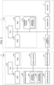
- FIG. 3 is a block diagram illustrating examples of hardware configurations of the shopping cart 1 and the mobile terminal 2 according to the embodiment.
- the shopping cart 1 includes a controller 100, which includes a Central Processing Unit (CPU) 101, a Read Only Memory (ROM) 102, a Random Access Memory (RAM) 103, and a storage device 104, the battery 7, the power transmitter 11, and the connector 12.
- the storage device 104 stores a control program 105.
- the CPU 101 is an example of a processor and controls operations of the battery 7, the power transmitter 11, and the connector 12 related to the charging of the battery 7.
- the ROM 102 stores various programs.
- the RAM 103 is a workspace into which programs and various types of data are loaded.
- the CPU 101, the ROM 102, and the RAM 103 are connected to each other via a bus, and the CPU 101, the ROM 102, the RAM 103, and the storage device 104 constitute the controller 100 of the shopping cart 1.
- the storage device 104 is implemented by a non-volatile memory, such as a Hard Disc Drive (HDD) or a flash memory, that retains programs and data even when power is turned off.
- the storage device 104 stores the control program 105 for controlling the shopping cart 1.
- the mobile terminal 2 includes the power receiver 21, a CPU 201, a ROM 202, a RAM 203, a storage device 204, a display device 207, and an operating unit 208.
- the storage device 204 stores a control program 205 and a purchase application 206.
- the CPU 201 is an example of a processor and controls the components of the mobile terminal 2.
- the ROM 202 stores various programs.
- the RAM 203 is a workspace into which programs and various types of data are loaded.
- the storage device 204 stores various programs.
- the CPU 201, the ROM 202, the RAM 203, and the storage device 204 are connected to each other via a bus.
- the CPU 201, the ROM 202, and the RAM 203 constitute the controller 200 of the mobile terminal 2.
- the controller 200 performs a control process in cooperation with the controller 100 of the shopping cart 1 by controlling the CPU 201 in accordance with a program stored in the ROM 202 or the storage device 204 and loaded into the RAM 203.
- the storage device 204 is implemented by a non-volatile memory, such as a Hard Disc Drive (HDD) or a flash memory, that retains programs and data even when power is turned off.
- the storage device 204 stores the control program 205 and the purchase application 206.
- the control program 205 is for controlling the mobile terminal 2.
- the purchase application 206 is for supporting registration and payment of items to be purchased. Specifically, the purchase application 206 registers items to be purchased via the operating unit 208 described later. In addition, the purchase application 206 supports the customer in purchasing items by displaying registered items on the display device 207 described later.
- the display device 207 is, for example, a Liquid Crystal Display (LCD).
- the display device 207 displays various types of data under the control of the CPU 201.
- the operating unit 208 is a touch panel provided on the display device 207.
- the operating unit 208 outputs operations input via the touch panel to the CPU 201.
- the operating unit 208 may also include, for example, a keyboard and/or a pointing device.
- the operating unit 208 is an example of an input device.
- the connector 12 is a connection interface to which the battery 7 and the power transmitter 11 are connected.
- the connector 12 is connected between the battery 7 and the power transmitter 11.
- the connector 12 includes a switch that is switched on and off to start and stop the power supply from the battery 7 to the power transmitter 11 that is electrically connected to the battery 7 via the connector 12 and the connection cable La.
- FIG. 4 is a diagram illustrating an example of a functional configuration of the controller 100 according to the embodiment.
- the controller 100 includes a connection detection unit 111, a charging control unit 112, and a display control unit 113 as functional components.
- the controller 100 (CPU 101) of the shopping cart 1 implements the above-described functional components by executing the control program 105 stored in the storage device 104 (or a non-transitory computer-readable storage medium).
- the above-described functional components are software components implemented by the cooperation between the processor and the program of the shopping cart 1.
- the present invention is not limited to this embodiment.
- some or all of the above-described functional components may be implemented by dedicated circuits or the like.
- the connection detection unit 111 is an example of a detection unit.
- the connection detection unit 111 When the mobile terminal 2 is connected to the power transmitter 11, the connection detection unit 111 outputs a detection signal to the CPU 101. Specifically, the connection detection unit 111 electrically detects, via the power transmitter 11, that the power receiver 21 of the mobile terminal 2 is connected to the power transmitter 11 and transmits a detection signal to the charging control unit 112 described later.
- the charging control unit 112 controls the electric power supplied from the battery 7 to the power transmitter 11 in accordance with the state of the mobile terminal 2 attached to the attachment 9. Specifically, upon receiving the detection signal from the connection detection unit 111, the charging control unit 112 accesses the mobile terminal 2 via the power transmitter 11 to determine the remaining battery charge of the mobile terminal 2 as an example of a state of the mobile terminal 2.
- the charging control unit 112 determines that the mobile terminal 2 needs to be charged and turns on the connector 12 (or the switch of the connector 12) to start the power supply. Then, the charging control unit 112 notifies the display control unit 113 that the charging of the mobile terminal 2 is started. On the other hand, when the remaining battery charge of the mobile terminal 2 is not less than the preset threshold value, the charging control unit 112 determines that the charging of the mobile terminal 2 is unnecessary and turns off the connector 12 (or the switch of the connector 12). Then, the charging control unit 112 notifies the display control unit 113 that the charging of the mobile terminal 2 is not performed.
- the charging control unit 112 determines to stop the charging of the mobile terminal 2 and turns off the connector 12. Then, the charging control unit 112 notifies the display control unit 113 that the charging of the mobile terminal 2 is stopped. For example, when the mobile terminal 2 is in the fully charged state, the charging is stopped. With this configuration, unnecessary power consumption of the battery 7 can be prevented.
- the display control unit 113 displays a charging state of the mobile terminal 2 on the display device 207 of the mobile terminal 2.
- the charging state indicates, for example, whether the charging of the mobile terminal 2 is started, not started, or stopped.
- the display control unit 113 causes the display device 207 to display a message indicating that the charging is started when the charging of the mobile terminal 2 is necessary, and causes the display unit 207 to display a message indicating that the charging of the mobile terminal 2 is not started when the charging is unnecessary, that is, when the remaining battery charge is sufficient.
- the charging state is displayed on the display device 207 of the mobile terminal 2.
- the present invention is not limited to this embodiment, and the display of the charging state may be omitted.
- the display control unit 113 may be removed from the functional configuration of the controller 100.
- FIG. 5 is a flowchart illustrating an example of a process of charging the mobile terminal 2 according to the embodiment.
- the connection detection unit 111 waits while the connection between the power transmitter 11 and the power receiver 21 is not detected (step S1: No). In other words, the connection detection unit 111 determines whether the mobile terminal 2 is connected to the power transmitter 11. When detecting the connection between the power transmitter 11 and the power receiver 21 (step S1: Yes), the connection detection unit 111 notifies the charging control unit 112 that the connection between the mobile terminal 2 and the battery 7 has been detected.
- the charging control unit 112 determines the remaining battery charge of the mobile terminal 2 via the power receiver 21 (step S2).
- the charging control unit 112 turns off the connector 12.
- the charging control unit 112 notifies the display control unit 113 that the remaining battery charge is sufficient.
- the display control unit 113 displays, on the display device 207, a message indicating that the charging of the mobile terminal 2 is not started because the remaining battery charge is sufficient (step S3), and ends the process.
- step S2 when the remaining battery charge is less than the preset threshold value (step S2: Yes), the charging control unit 112 turns on the connector 12. Then, the charging control unit 112 notifies the display control unit 113 that the charging of the mobile terminal 2 is started. When receiving the notification, the display control unit 113 causes the display device 207 to display a message indicating that the charging is started (step S4).
- the charging control unit 112 determines the remaining battery charge of the mobile terminal 2 via the power receiver 21 (step S5).
- step S5 when the remaining battery charge is less than the preset threshold value (step S5: No), step S5 is repeated.
- the charging control unit 112 turns off the connector 12. Then, the charging control unit 112 notifies the display control unit 113 that the charging is stopped.
- the display control unit 113 causes the display device 207 to display a message indicating that the charging is stopped (step S6), and ends the process.
- the shopping cart 1 of the present embodiment when it is detected that the mobile terminal 2 attached to the attachment 9 of the shopping cart 1 is connected to the battery 7, the remaining battery charge of the mobile terminal 2 is determined.
- the charging control unit 112 of the shopping cart 1 starts charging the mobile terminal 2.
- the charging control unit 112 of the shopping cart 1 stops or does not start charging the mobile terminal 2.
- any type of information may be displayed on the display device 207.
- the above-described embodiment can be modified as appropriate by changing some of the configurations or functions of the above-described apparatuses. Below, some variations of the above-described embodiment will be described. In the descriptions below, differences from the above-described embodiment will be mainly discussed, and detailed descriptions of the same components and features as those described above will be omitted. Furthermore, the variations described below may be implemented individually or in any appropriate combination.
- connection detection unit 111 when the connection detection unit 111 detects the connection at step S2 in FIG. 5 , it is determined whether the remaining battery charge of the mobile terminal 2 is less than the threshold value. In the first variation, before or after the execution of step S2, the connection detection unit 111 determines, as an example of a state of the mobile terminal 2, whether a purchase application is installed in the mobile terminal 2 and controls the charging of the mobile terminal 2 according to the determination result. A process of charging the mobile terminal 2 according to the first variation will be described below with reference to FIG. 6 .
- FIG. 6 is a flowchart illustrating a process of charging the mobile terminal 2 according to the first variation. Descriptions of steps that are the same as those in FIG. 5 will be omitted.
- the charging control unit 112 Upon receiving notification from the connection detection unit 111, the charging control unit 112 determines, via the power receiver 21, whether a purchase application is installed in the mobile terminal 2 (step S11). When the purchase application is not installed (step S11: No), the charging control unit 112 causes the display device 207 to display a screen prompting to install the purchase application (step S12), and ends the process.
- step S11 When the purchase application is installed in the mobile terminal 2 (step S11: Yes), the charging control unit 112 turns on the connector 12. Next, the charging control unit 112 notifies the display control unit 113 that the charging of the mobile terminal 2 is started. When receiving the notification, the display control unit 113 causes the display device 207 to display a message indicating that the charging is started (step S13).
- the charging control unit 112 determines the remaining battery charge of the mobile terminal 2 via the power receiver 21 (step S14). When the remaining battery charge is less than the preset threshold value (step S14: No), step 14 is repeated. When the remaining battery charge is greater than or equal to the preset threshold value (step S14: Yes), the charging control unit 112 turns off the connector 12 and notifies the display control unit 113 that the charging is stopped. When receiving the notification, the display control unit 113 causes the display device 207 to display a message indicating that the charging is stopped (step S15), and ends the process.
- the shopping cart 1 of the first variation whether the purchase application is installed is determined.
- the purchase application is not installed, the charging of the mobile terminal 2 is not performed, and the installation of the application is prompted.
- the electric power of the battery 7 is not used for charging the mobile terminal 2 for the purpose unrelated to purchasing, and unnecessary electric power consumption of the battery 7 can be prevented. That is, the first variation makes it possible to efficiently charge the mobile terminal 2.
- the charging control unit 112 turns on the connector 12 at step S13 in FIG. 6 . Then, the charging control unit 112 notifies the display control unit 113 that the charging of the mobile terminal 2 is started. When receiving the notification, the display control unit 113 displays a message indicating that the charging is started on the display device 207.
- the charging control unit 112 determines, as an example of the state of the mobile terminal 2, whether the purchase application is running and controls the charging of the mobile terminal 2 according to the determination result. Below, with reference to FIG. 7 , a process of charging the mobile terminal 2 according to the second variation will be described.
- FIG. 7 is a flowchart illustrating an example of a process of charging the mobile terminal 2 according to the second variation. Descriptions of steps that are the same as those in FIGS. 5 and 6 will be omitted.
- step S11 When the purchase application is installed in the mobile terminal 2 (step S11: Yes), the charging control unit 112 determines whether the purchase application is running (step S21). When the purchase application is not running (step S21: No), a screen prompting to start the purchase application is displayed on the display device 207 (step S22).
- step S21 When the purchase application is running (step S21: Yes), the charging control unit 112 turns on the connector 12. Next, the charging control unit 112 notifies the display control unit 113 that the charging of the mobile terminal 2 is started. When receiving the notification, the display control unit 113 causes the display device 207 to display a message indicating that the charging is started (step S23).
- step S24 determines the remaining battery charge of the mobile terminal 2 via the power receiver 21 (step S24). When the remaining battery charge is less than the preset threshold value (step S24: No), step S24 is repeated. When the remaining battery charge is greater than or equal to the preset threshold value (step S24: Yes), the charging control unit 112 turns off the connector 12. Next, the charging control unit 112 notifies the display control unit 113 that the charging is stopped. When receiving the notification, the display control unit 113 causes the display device 207 to display a message indicating that the charging is stopped (step S25), and ends the process.
- the shopping cart 1 of the second variation it is determined whether the purchase application is running.
- the purchase application is not running, the charging of the mobile terminal 2 is not performed, and the start of the purchase application is prompted.
- the second variation makes it possible to prevent the electric energy of the battery 7 from being used for charging the mobile terminal 2 for the purpose unrelated to purchasing. Therefore, in the shopping cart 1 of the second variation, unnecessary power consumption of the battery 7 can be prevented, and the charging of the mobile terminal 2 can be efficiently performed.
- step S2 of FIG. 5 when receiving notification from the connection detection unit 111, the charging control unit 112 determines the remaining battery charge of the mobile terminal 2 via the power receiver 21. In the third variation, step S2 is omitted.
- step S1 when detecting that the power transmitter 11 is connected to the power receiver 21 (step S1: Yes), the connection detection unit 111 notifies the charging control unit 112 that the mobile terminal 2 is connected to the battery 7. Next, upon receiving the notification from the connection detection unit 111, the charging control unit 112 turns on the connector 12. Then, the charging control unit 112 notifies the display control unit 113 that the charging of the mobile terminal 2 is started. When receiving the notification, the display control unit 113 causes the display device 207 to display a message indicating that the charging is started (step S4).
- the step of determining the remaining battery charge of the mobile terminal 2 is not performed. This makes it possible to charge the mobile terminal 2 regardless of the remaining battery charge of the mobile terminal 2. For example, this makes it possible to charge the mobile terminal 2 even when the remaining battery charge of the mobile terminal 2 is zero.
- Programs executed by the shopping cart 1 according to the embodiment and the variations may be stored in a computer connected to a network, such as the Internet, and may be downloaded via the network. Furthermore, programs executed by the shopping cart 1 according to the embodiment and the variations may be provided or distributed via a network such as the Internet.
- Programs executed by the apparatuses according to the above-described embodiment may be provided in advance in a ROM, a storage device, or the like.
- Programs executed by the apparatuses according to the above-described embodiment may be provided in a non-transitory computer-readable storage medium, such as a compact disc read-only memory (CD-ROM), a flexible disk (FD), a compact disc recordable (CD-R), or a digital versatile disk (DVD) in an installable format or an executable format.
- CD-ROM compact disc read-only memory
- FD flexible disk
- CD-R compact disc recordable
- DVD digital versatile disk
- programs executed by the apparatuses according to the above-described embodiment may be stored in a computer connected to a network, such as the Internet, and may be downloaded via the network. Furthermore, programs executed by the apparatuses according to the above-described embodiment may be provided or distributed via a network such as the Internet.
Landscapes
- Engineering & Computer Science (AREA)
- Power Engineering (AREA)
- Chemical & Material Sciences (AREA)
- Combustion & Propulsion (AREA)
- Transportation (AREA)
- Mechanical Engineering (AREA)
- Theoretical Computer Science (AREA)
- General Engineering & Computer Science (AREA)
- Computer Hardware Design (AREA)
- General Physics & Mathematics (AREA)
- Physics & Mathematics (AREA)
- Charge And Discharge Circuits For Batteries Or The Like (AREA)
- Handcart (AREA)
Abstract
A shopping cart includes an attachment to which a mobile terminal is attachable, a battery, a power transmitter electrically connectable to the mobile terminal attached to the attachment and configured to transmit electric power supplied from the battery to the mobile terminal, a switch connected between the battery and the power transmitter, and a processor configured to determine a state of the mobile terminal attached to the attachment and turn on or off the switch to control supply of the electric power from the battery to the power transmitter based on the determined state of the mobile terminal.
Description
- Embodiments described herein relate generally to a shopping cart, a charging method, and a storage medium.
- Among mobile objects, such as carts (hereinafter referred to as shopping carts), used in stores such as supermarkets and retailers, there is a shopping cart to which a mobile terminal of a customer can be attached.
- With such a shopping cart, it is possible to smoothly perform registration and payment of items to be purchased by installing a dedicated application in advance in the mobile terminal of the customer.
- On the other hand, whether shopping using the shopping cart as described above proceeds smoothly depends on the state (e.g., the remaining battery charge) of the mobile terminal in which the application is installed. For example, when the battery of the mobile terminal runs out and the application cannot be used, shopping cannot be done smoothly.
- The related-art technology described above proposes a configuration in which a portable terminal can be charged while being placed in a holder for holding the portable terminal. With this configuration, however, a customer needs to bring a battery, and there is room for improvement in terms of convenience.
- Embodiments of the present invention provide a shopping cart, a charging method, and a storage medium capable of charging a mobile terminal.
- According to an embodiment, a shopping cart comprises an attachment to which a mobile terminal is attachable; a battery; a power transmitter electrically connectable to the mobile terminal attached to the attachment and configured to transmit electric power supplied from the battery to the mobile terminal; a switch connected between the battery and the power transmitter; and a processor configured to determine a state of the mobile terminal attached to the attachment and turn on or off the switch to control supply of the electric power from the battery to the power transmitter based on the determined state of the mobile terminal.
- The present invention also relates to a charging method performed by a controller of a shopping cart according to appended claims.
- The method may further comprise the following features :
- In determining the state of the mobile terminal, whether a predetermined application is installed in the mobile terminal is determined, a step of turning on the switch to supply the electric power from the battery to the power transmitter when the predetermined application is installed in the mobile terminal and.
- A step of causing a display device of the mobile terminal to display a screen prompting to install the predetermined application in the mobile terminal when the predetermined application is not installed in the mobile terminal.
- In determining the state of the mobile terminal, whether a predetermined application installed in the mobile terminal is running is determined, and turning on the switch to supply the electric power from the battery to the power transmitter when the predetermined application is running.
- A step of causing a display device of the mobile terminal to display a screen prompting to start the predetermined application when the predetermined application is not running.
- A step of causing a display device of the mobile terminal to display a charging state indicating whether charging of the mobile terminal is started, not started, or stopped.
-
-
FIG. 1 is a side view of a configuration of a shopping cart according to an embodiment. -
FIG. 2 is a schematic diagram illustrating a configuration of an attachment of the shopping cart according to the embodiment. -
FIG. 3 is a block diagram illustrating hardware configurations of the shopping cart and a mobile terminal according to the embodiment. -
FIG. 4 is a diagram illustrating a functional configuration of a controller according to the embodiment. -
FIG. 5 is a flowchart illustrating a process of charging of a mobile terminal according to the embodiment. -
FIG. 6 is a flowchart illustrating a process of charging a mobile terminal according to a first variation. -
FIG. 7 is a flowchart illustrating a process of charging a mobile terminal according to a second variation. - Hereinafter, a shopping cart, a charging method, and a storage medium according to an embodiment will be described with reference to the drawings. However, the present invention is not limited by the embodiment described below. Moreover, various omissions, substitutions, changes, and combinations of components can be made without departing from the scope of the embodiment described below.
-
FIG. 1 is a side view illustrating an example of a configuration of ashopping cart 1 according to the embodiment. As illustrated inFIG. 1 , theshopping cart 1 includes ahandle 3, asupport 4,casters 5, acontainer 6, abattery 7, anattachment 9, apower transmitter 11, and a connection cable La. Amobile terminal 2 is attachable to theattachment 9. - The
shopping cart 1 is an example of a mobile object and is provided in a store such as a supermarket. Theshopping cart 1 is a device used by a customer to store items to be purchased while moving in a store. Theshopping cart 1 is pushed and moved by the customer inside of the store. - The
mobile terminal 2 is a device, such as a smartphone. Themobile terminal 2 is detachably attachable to theattachment 9. Specifically, themobile terminal 2 is owned by the customer. For example, an application program for performing registration and payment of items to be purchased is installed in themobile terminal 2. Hereinafter, this application program is also referred to as a purchase application. Themobile terminal 2 is used for shopping in the store. Themobile terminal 2 may be a tablet terminal. Furthermore, themobile terminal 2 may be lent to the customer by the store. - The
mobile terminal 2 is charged by receiving electric power supplied from the shopping cart 1 (or the battery 7) via theattachment 9. Specifically, themobile terminal 2 is electrically connected to thebattery 7 by connecting apower receiver 21 of themobile terminal 2, which will be described later, to thepower transmitter 11 of theattachment 9 via a connection cable Lb. - The
handle 3 is a component that the customer grips when moving theshopping cart 1. Thesupport 4 is provided, for example, on thehandle 3 and supports theattachment 9. - The
casters 5 serve as points of contact of theshopping cart 1 with the ground. Thecasters 5 are examples of wheels. Thecontainer 6 has a cage-like shape with an upper opening and stores items such that the items can be visually recognized from the outside. Theshopping cart 1 does not need to include thecontainer 6 in itself and may include, for example, a basket receiver for receiving a shopping basket as thecontainer 6. - The
battery 7 is a rechargeable secondary battery. Thebattery 7 stores electric power supplied from an external power source via a power supply unit (not shown) and supplies the stored electric power to, for example, themobile terminal 2 mounted on theshopping cart 1. - The
attachment 9 is a holder for holding themobile terminal 2 and thereby fixing themobile terminal 2 to theshopping cart 1. Specifically, theattachment 9 has, for example, a substantially rectangular shape and is fixed to theshopping cart 1 by thesupport 4. Note that the shape of theattachment 9 is not limited to a substantially rectangular shape and may be any shape that can hold themobile terminal 2. - The
power transmitter 11 is a terminal provided on theattachment 9. Specifically, thepower transmitter 11 electrically connects thebattery 7 to themobile terminal 2 by connecting themobile terminal 2 to the connection cable La via thepower receiver 21 and the connection cable Lb which will be described later. This makes it possible to charge themobile terminal 2 with the electric power of thebattery 7. - Note that the configuration of the
shopping cart 1 is not limited to the example illustrated inFIG. 1 . For example, theshopping cart 1 may include an imaging device and a weight sensor to which electric power is supplied by thebattery 7. - Next, the
attachment 9 will be described in detail with reference toFIG. 2. FIG. 2 is a schematic diagram illustrating an example of the configuration of theattachment 9 of theshopping cart 1 according to the embodiment. Note thatFIG. 2 illustrates a state in which themobile terminal 2 is attached to theattachment 9. - The
attachment 9 holds themobile terminal 2. Theattachment 9 includes anedge holder 22 for holding the left and right edges of themobile terminal 2 and thepower transmitter 11. Thepower receiver 21 is a connection terminal of themobile terminal 2. Specifically, thepower receiver 21 is electrically connected to thepower transmitter 11 via the connection cable Lb. - When the
mobile terminal 2 is attached to theattachment 9, thepower receiver 21 of themobile terminal 2 and thepower transmitter 11 of theattachment 9 are electrically connected to each other via the connection cable Lb. As shown inFIG. 3 , thebattery 7 is electrically connected to thepower transmitter 11 via the connection cable La and aconnector 12, which will be described later. With this configuration, thebattery 7 is electrically connected to thepower receiver 21, and themobile terminal 2 can be charged. - Note that, although the
power transmitter 11 and thepower receiver 21 are electrically connected to each other via the connection cable Lb, thepower transmitter 11 and thepower receiver 21 may be directly connected to each other without using the connection cable Lb. For example, thepower receiver 21 of themobile terminal 2 and thepower transmitter 11 of theattachment 9 may be wirelessly connected to each other. - Next, hardware configurations of the
shopping cart 1 and themobile terminal 2 will be described with reference toFIG. 3. FIG. 3 is a block diagram illustrating examples of hardware configurations of theshopping cart 1 and themobile terminal 2 according to the embodiment. As illustrated inFIG. 3 , theshopping cart 1 includes acontroller 100, which includes a Central Processing Unit (CPU) 101, a Read Only Memory (ROM) 102, a Random Access Memory (RAM) 103, and astorage device 104, thebattery 7, thepower transmitter 11, and theconnector 12. Thestorage device 104 stores acontrol program 105. - The
CPU 101 is an example of a processor and controls operations of thebattery 7, thepower transmitter 11, and theconnector 12 related to the charging of thebattery 7. TheROM 102 stores various programs. TheRAM 103 is a workspace into which programs and various types of data are loaded. TheCPU 101, theROM 102, and theRAM 103 are connected to each other via a bus, and theCPU 101, theROM 102, theRAM 103, and thestorage device 104 constitute thecontroller 100 of theshopping cart 1. - The
storage device 104 is implemented by a non-volatile memory, such as a Hard Disc Drive (HDD) or a flash memory, that retains programs and data even when power is turned off. Thestorage device 104 stores thecontrol program 105 for controlling theshopping cart 1. - The
mobile terminal 2 includes thepower receiver 21, aCPU 201, aROM 202, aRAM 203, astorage device 204, adisplay device 207, and an operating unit 208. Thestorage device 204 stores acontrol program 205 and apurchase application 206. - The
CPU 201 is an example of a processor and controls the components of themobile terminal 2. TheROM 202 stores various programs. TheRAM 203 is a workspace into which programs and various types of data are loaded. Thestorage device 204 stores various programs. - The
CPU 201, theROM 202, theRAM 203, and thestorage device 204 are connected to each other via a bus. Here, theCPU 201, theROM 202, and theRAM 203 constitute thecontroller 200 of themobile terminal 2. Thecontroller 200 performs a control process in cooperation with thecontroller 100 of theshopping cart 1 by controlling theCPU 201 in accordance with a program stored in theROM 202 or thestorage device 204 and loaded into theRAM 203. - The
storage device 204 is implemented by a non-volatile memory, such as a Hard Disc Drive (HDD) or a flash memory, that retains programs and data even when power is turned off. Thestorage device 204 stores thecontrol program 205 and thepurchase application 206. Thecontrol program 205 is for controlling themobile terminal 2. - The
purchase application 206 is for supporting registration and payment of items to be purchased. Specifically, thepurchase application 206 registers items to be purchased via the operating unit 208 described later. In addition, thepurchase application 206 supports the customer in purchasing items by displaying registered items on thedisplay device 207 described later. - The
display device 207 is, for example, a Liquid Crystal Display (LCD). Thedisplay device 207 displays various types of data under the control of theCPU 201. The operating unit 208 is a touch panel provided on thedisplay device 207. The operating unit 208 outputs operations input via the touch panel to theCPU 201. The operating unit 208 may also include, for example, a keyboard and/or a pointing device. The operating unit 208 is an example of an input device. - The
connector 12 is a connection interface to which thebattery 7 and thepower transmitter 11 are connected. In other words, theconnector 12 is connected between thebattery 7 and thepower transmitter 11. For example, theconnector 12 includes a switch that is switched on and off to start and stop the power supply from thebattery 7 to thepower transmitter 11 that is electrically connected to thebattery 7 via theconnector 12 and the connection cable La. - Next, the
controller 100 of theshopping cart 1 will be described with reference toFIG. 4. FIG. 4 is a diagram illustrating an example of a functional configuration of thecontroller 100 according to the embodiment. As illustrated inFIG. 4 , thecontroller 100 includes aconnection detection unit 111, a chargingcontrol unit 112, and adisplay control unit 113 as functional components. - Specifically, the controller 100 (CPU 101) of the
shopping cart 1 implements the above-described functional components by executing thecontrol program 105 stored in the storage device 104 (or a non-transitory computer-readable storage medium). In the present embodiment, the above-described functional components are software components implemented by the cooperation between the processor and the program of theshopping cart 1. However, the present invention is not limited to this embodiment. For example, some or all of the above-described functional components may be implemented by dedicated circuits or the like. - The
connection detection unit 111 is an example of a detection unit. When themobile terminal 2 is connected to thepower transmitter 11, theconnection detection unit 111 outputs a detection signal to theCPU 101. Specifically, theconnection detection unit 111 electrically detects, via thepower transmitter 11, that thepower receiver 21 of themobile terminal 2 is connected to thepower transmitter 11 and transmits a detection signal to the chargingcontrol unit 112 described later. - The charging
control unit 112 controls the electric power supplied from thebattery 7 to thepower transmitter 11 in accordance with the state of themobile terminal 2 attached to theattachment 9. Specifically, upon receiving the detection signal from theconnection detection unit 111, the chargingcontrol unit 112 accesses themobile terminal 2 via thepower transmitter 11 to determine the remaining battery charge of themobile terminal 2 as an example of a state of themobile terminal 2. - When the remaining battery charge of the
mobile terminal 2 is less than a preset threshold value, the chargingcontrol unit 112 determines that themobile terminal 2 needs to be charged and turns on the connector 12 (or the switch of the connector 12) to start the power supply. Then, the chargingcontrol unit 112 notifies thedisplay control unit 113 that the charging of themobile terminal 2 is started. On the other hand, when the remaining battery charge of themobile terminal 2 is not less than the preset threshold value, the chargingcontrol unit 112 determines that the charging of themobile terminal 2 is unnecessary and turns off the connector 12 (or the switch of the connector 12). Then, the chargingcontrol unit 112 notifies thedisplay control unit 113 that the charging of themobile terminal 2 is not performed. - When the charging of the
mobile terminal 2 is performed and the remaining battery charge of themobile terminal 2 becomes greater than or equal to the preset threshold value, the chargingcontrol unit 112 determines to stop the charging of themobile terminal 2 and turns off theconnector 12. Then, the chargingcontrol unit 112 notifies thedisplay control unit 113 that the charging of themobile terminal 2 is stopped. For example, when themobile terminal 2 is in the fully charged state, the charging is stopped. With this configuration, unnecessary power consumption of thebattery 7 can be prevented. - Note that it is desirable to set the threshold value of the remaining battery charge based on the electric power with which the
purchase application 206 can stably operate so as not to waste the electric energy stored in thebattery 7 due to unnecessary charging of themobile terminal 2. - The
display control unit 113 displays a charging state of themobile terminal 2 on thedisplay device 207 of themobile terminal 2. The charging state indicates, for example, whether the charging of themobile terminal 2 is started, not started, or stopped. Specifically, when receiving notification indicating whether the charging is necessary from the chargingcontrol unit 112, thedisplay control unit 113 causes thedisplay device 207 to display a message indicating that the charging is started when the charging of themobile terminal 2 is necessary, and causes thedisplay unit 207 to display a message indicating that the charging of themobile terminal 2 is not started when the charging is unnecessary, that is, when the remaining battery charge is sufficient. - In the present embodiment, the charging state is displayed on the
display device 207 of themobile terminal 2. However, the present invention is not limited to this embodiment, and the display of the charging state may be omitted. In this case, thedisplay control unit 113 may be removed from the functional configuration of thecontroller 100. - Next, a process of charging the
mobile terminal 2 will be described with reference toFIG. 5. FIG. 5 is a flowchart illustrating an example of a process of charging themobile terminal 2 according to the embodiment. - The
connection detection unit 111 waits while the connection between thepower transmitter 11 and thepower receiver 21 is not detected (step S1: No). In other words, theconnection detection unit 111 determines whether themobile terminal 2 is connected to thepower transmitter 11. When detecting the connection between thepower transmitter 11 and the power receiver 21 (step S1: Yes), theconnection detection unit 111 notifies the chargingcontrol unit 112 that the connection between themobile terminal 2 and thebattery 7 has been detected. - Next, upon receiving the notification from the
connection detection unit 111, the chargingcontrol unit 112 determines the remaining battery charge of themobile terminal 2 via the power receiver 21 (step S2). Here, when the remaining battery charge is not less than the preset threshold value (step S2: No), the chargingcontrol unit 112 turns off theconnector 12. Then, the chargingcontrol unit 112 notifies thedisplay control unit 113 that the remaining battery charge is sufficient. When receiving the notification, thedisplay control unit 113 displays, on thedisplay device 207, a message indicating that the charging of themobile terminal 2 is not started because the remaining battery charge is sufficient (step S3), and ends the process. - On the other hand, when the remaining battery charge is less than the preset threshold value (step S2: Yes), the charging
control unit 112 turns on theconnector 12. Then, the chargingcontrol unit 112 notifies thedisplay control unit 113 that the charging of themobile terminal 2 is started. When receiving the notification, thedisplay control unit 113 causes thedisplay device 207 to display a message indicating that the charging is started (step S4). - Next, the charging
control unit 112 determines the remaining battery charge of themobile terminal 2 via the power receiver 21 (step S5). Here, when the remaining battery charge is less than the preset threshold value (step S5: No), step S5 is repeated. When the remaining battery charge is greater than or equal to the preset threshold value (step S5: Yes), the chargingcontrol unit 112 turns off theconnector 12. Then, the chargingcontrol unit 112 notifies thedisplay control unit 113 that the charging is stopped. When receiving the notification, thedisplay control unit 113 causes thedisplay device 207 to display a message indicating that the charging is stopped (step S6), and ends the process. - As described above, in the
shopping cart 1 of the present embodiment, when it is detected that themobile terminal 2 attached to theattachment 9 of theshopping cart 1 is connected to thebattery 7, the remaining battery charge of themobile terminal 2 is determined. When charging is necessary, the chargingcontrol unit 112 of theshopping cart 1 starts charging themobile terminal 2. When charging is not necessary, the chargingcontrol unit 112 of theshopping cart 1 stops or does not start charging themobile terminal 2. This configuration makes it possible to prevent unnecessary power consumption of thebattery 7 while supplying sufficient power for using the purchase application installed in themobile terminal 2, and thereby makes it possible to efficiently charge themobile terminal 2. - In the above-described embodiment, instead of messages, any type of information may be displayed on the
display device 207. Also, the above-described embodiment can be modified as appropriate by changing some of the configurations or functions of the above-described apparatuses. Below, some variations of the above-described embodiment will be described. In the descriptions below, differences from the above-described embodiment will be mainly discussed, and detailed descriptions of the same components and features as those described above will be omitted. Furthermore, the variations described below may be implemented individually or in any appropriate combination. - A first variation of the above-described embodiment will be described below. In the above-described embodiment, when the
connection detection unit 111 detects the connection at step S2 inFIG. 5 , it is determined whether the remaining battery charge of themobile terminal 2 is less than the threshold value. In the first variation, before or after the execution of step S2, theconnection detection unit 111 determines, as an example of a state of themobile terminal 2, whether a purchase application is installed in themobile terminal 2 and controls the charging of themobile terminal 2 according to the determination result. A process of charging themobile terminal 2 according to the first variation will be described below with reference toFIG. 6 . -
FIG. 6 is a flowchart illustrating a process of charging themobile terminal 2 according to the first variation. Descriptions of steps that are the same as those inFIG. 5 will be omitted. - Upon receiving notification from the
connection detection unit 111, the chargingcontrol unit 112 determines, via thepower receiver 21, whether a purchase application is installed in the mobile terminal 2 (step S11). When the purchase application is not installed (step S11: No), the chargingcontrol unit 112 causes thedisplay device 207 to display a screen prompting to install the purchase application (step S12), and ends the process. - When the purchase application is installed in the mobile terminal 2 (step S11: Yes), the charging
control unit 112 turns on theconnector 12. Next, the chargingcontrol unit 112 notifies thedisplay control unit 113 that the charging of themobile terminal 2 is started. When receiving the notification, thedisplay control unit 113 causes thedisplay device 207 to display a message indicating that the charging is started (step S13). - Next, the charging
control unit 112 determines the remaining battery charge of themobile terminal 2 via the power receiver 21 (step S14). When the remaining battery charge is less than the preset threshold value (step S14: No),step 14 is repeated. When the remaining battery charge is greater than or equal to the preset threshold value (step S14: Yes), the chargingcontrol unit 112 turns off theconnector 12 and notifies thedisplay control unit 113 that the charging is stopped. When receiving the notification, thedisplay control unit 113 causes thedisplay device 207 to display a message indicating that the charging is stopped (step S15), and ends the process. - As described above, in the
shopping cart 1 of the first variation, whether the purchase application is installed is determined. When the purchase application is not installed, the charging of themobile terminal 2 is not performed, and the installation of the application is prompted. With this configuration, the electric power of thebattery 7 is not used for charging themobile terminal 2 for the purpose unrelated to purchasing, and unnecessary electric power consumption of thebattery 7 can be prevented. That is, the first variation makes it possible to efficiently charge themobile terminal 2. - Next, a variation of the first variation is described as a second variation. In the first variation described above, when the purchase application is installed in the
mobile terminal 2, the chargingcontrol unit 112 turns on theconnector 12 at step S13 inFIG. 6 . Then, the chargingcontrol unit 112 notifies thedisplay control unit 113 that the charging of themobile terminal 2 is started. When receiving the notification, thedisplay control unit 113 displays a message indicating that the charging is started on thedisplay device 207. In the second variation, when it is determined that the purchase application is installed, the chargingcontrol unit 112 determines, as an example of the state of themobile terminal 2, whether the purchase application is running and controls the charging of themobile terminal 2 according to the determination result. Below, with reference toFIG. 7 , a process of charging themobile terminal 2 according to the second variation will be described. -
FIG. 7 is a flowchart illustrating an example of a process of charging themobile terminal 2 according to the second variation. Descriptions of steps that are the same as those inFIGS. 5 and6 will be omitted. - When the purchase application is installed in the mobile terminal 2 (step S11: Yes), the charging
control unit 112 determines whether the purchase application is running (step S21). When the purchase application is not running (step S21: No), a screen prompting to start the purchase application is displayed on the display device 207 (step S22). - When the purchase application is running (step S21: Yes), the charging
control unit 112 turns on theconnector 12. Next, the chargingcontrol unit 112 notifies thedisplay control unit 113 that the charging of themobile terminal 2 is started. When receiving the notification, thedisplay control unit 113 causes thedisplay device 207 to display a message indicating that the charging is started (step S23). - Next, the charging
control unit 112 determines the remaining battery charge of themobile terminal 2 via the power receiver 21 (step S24). When the remaining battery charge is less than the preset threshold value (step S24: No), step S24 is repeated. When the remaining battery charge is greater than or equal to the preset threshold value (step S24: Yes), the chargingcontrol unit 112 turns off theconnector 12. Next, the chargingcontrol unit 112 notifies thedisplay control unit 113 that the charging is stopped. When receiving the notification, thedisplay control unit 113 causes thedisplay device 207 to display a message indicating that the charging is stopped (step S25), and ends the process. - As described above, in the
shopping cart 1 of the second variation, it is determined whether the purchase application is running. When the purchase application is not running, the charging of themobile terminal 2 is not performed, and the start of the purchase application is prompted. Thus, when the purchase application has been installed but has not been started, the second variation makes it possible to prevent the electric energy of thebattery 7 from being used for charging themobile terminal 2 for the purpose unrelated to purchasing. Therefore, in theshopping cart 1 of the second variation, unnecessary power consumption of thebattery 7 can be prevented, and the charging of themobile terminal 2 can be efficiently performed. - A third variation of the above-described embodiment will be described below. At step S2 of
FIG. 5 , when receiving notification from theconnection detection unit 111, the chargingcontrol unit 112 determines the remaining battery charge of themobile terminal 2 via thepower receiver 21. In the third variation, step S2 is omitted. - Specifically, when detecting that the
power transmitter 11 is connected to the power receiver 21 (step S1: Yes), theconnection detection unit 111 notifies the chargingcontrol unit 112 that themobile terminal 2 is connected to thebattery 7. Next, upon receiving the notification from theconnection detection unit 111, the chargingcontrol unit 112 turns on theconnector 12. Then, the chargingcontrol unit 112 notifies thedisplay control unit 113 that the charging of themobile terminal 2 is started. When receiving the notification, thedisplay control unit 113 causes thedisplay device 207 to display a message indicating that the charging is started (step S4). - As described above, in the
shopping cart 1 of the third variation, the step of determining the remaining battery charge of themobile terminal 2 is not performed. This makes it possible to charge themobile terminal 2 regardless of the remaining battery charge of themobile terminal 2. For example, this makes it possible to charge themobile terminal 2 even when the remaining battery charge of themobile terminal 2 is zero. - Programs executed by the
shopping cart 1 according to the embodiment and the variations may be stored in a computer connected to a network, such as the Internet, and may be downloaded via the network. Furthermore, programs executed by theshopping cart 1 according to the embodiment and the variations may be provided or distributed via a network such as the Internet. - Programs executed by the apparatuses according to the above-described embodiment may be provided in advance in a ROM, a storage device, or the like. Programs executed by the apparatuses according to the above-described embodiment may be provided in a non-transitory computer-readable storage medium, such as a compact disc read-only memory (CD-ROM), a flexible disk (FD), a compact disc recordable (CD-R), or a digital versatile disk (DVD) in an installable format or an executable format.
- Also, programs executed by the apparatuses according to the above-described embodiment may be stored in a computer connected to a network, such as the Internet, and may be downloaded via the network. Furthermore, programs executed by the apparatuses according to the above-described embodiment may be provided or distributed via a network such as the Internet.
- While certain embodiments have been described, these embodiments have been presented by way of example only, and are not intended to limit the scope of the disclosure. Indeed, the novel embodiments described herein may be embodied in a variety of other forms; furthermore, various omissions, substitutions and changes in the form of the embodiments described herein may be made without departing from the scope of the disclosure. The accompanying claims are intended to cover such forms or modifications as would fall within the scope of the disclosure.
Claims (15)
- A shopping cart (1) comprising:an attachment to which a mobile terminal is attachable;a battery (7);a power transmitter (11) electrically connectable to the mobile terminal attached to the attachment and configured to transmit electric power supplied from the battery to the mobile terminal;a switch (12) connected between the battery and the power transmitter; anda processor configured to determine a state of the mobile terminal attached to the attachment and turn on or off the switch to control supply of the electric power from the battery to the power transmitter based on the determined state of the mobile terminal.
- The shopping cart according to claim 1, wherein
the processor is configured to determine whether the mobile terminal is connected to the power transmitter and turn on the switch to supply the electric power from the battery to the power transmitter when the mobile terminal is connected to the power transmitter. - The shopping cart according to claim 1, wherein
the processor is configured to determine whether a remaining battery charge of the mobile terminal is less than a preset threshold value and turn on the switch to supply the electric power from the battery to the power transmitter when the remaining battery charge is less than the preset threshold value. - The shopping cart according to claim 3, wherein
the processor is configured to turn off the switch to stop supplying the electric power from the battery to the power transmitter when the remaining battery charge becomes greater than or equal to the preset threshold value while the mobile terminal is being charged. - The shopping cart according to claim 1, wherein
the processor is configured to determine whether a predetermined application is installed in the mobile terminal and turn on the switch to supply the electric power from the battery to the power transmitter when the predetermined application is installed in the mobile terminal. - The shopping cart according to claim 5, wherein
the processor is configured to cause a display device of the mobile terminal to display a screen prompting to install the predetermined application in the mobile terminal when the predetermined application is not installed in the mobile terminal. - The shopping cart according to claim 1, wherein
the processor is configured to determine whether a predetermined application installed in the mobile terminal is running and turn on the switch to supply the electric power from the battery to the power transmitter when the predetermined application is running. - The shopping cart according to claim 7, wherein
the processor is configured to cause a display device of the mobile terminal to display a screen prompting to start the predetermined application when the predetermined application is not running. - The shopping cart according to any one of claims 1 to 8, wherein
the processor is configured to cause a display device of the mobile terminal to display a charging state indicating whether charging of the mobile terminal is started, not started, or stopped. - The shopping cart according to any one of claims 1 to 9, further comprising:a handle on which the attachment is disposed; anda basket under which the battery is disposed.
- A charging method performed by a controller of a shopping cart including an attachment to which a mobile terminal is attachable, a battery, a power transmitter electrically connectable to the mobile terminal attached to the attachment and configured to transmit electric power from the battery to the mobile terminal, and a switch connected between the battery and the power transmitter, the charging method comprising:determining a state of the mobile terminal attached to the attachment; andturning on or off the switch to control supply of the electric power from the battery to the power transmitter based on the determined state of the mobile terminal.
- The charging method according to claim 11, whereinin determining the state of the mobile terminal, whether the mobile terminal is connected to the power transmitter is determined, andthe switch is turned on to supply the electric power from the battery to the power transmitter when the mobile terminal is connected to the power transmitter.
- The charging method according to claim 11, whereinin determining the state of the mobile terminal, whether a remaining battery charge of the mobile terminal is less than a preset threshold value is determined, andthe switch is turned on to supply the electric power from the battery to the power transmitter when the remaining battery charge is less than the preset threshold value.
- The charging method according to claim 13, wherein
the switch is turned off to stop supply of the electric power from the battery to the power transmitter when the remaining battery charge becomes greater than or equal to the preset threshold value while the mobile terminal is being charged. - . A non-transitory computer-readable storage medium storing a program for causing a processor of a shopping cart to execute a process, the shopping cart including an attachment to which a mobile terminal is attachable, a battery, a power transmitter electrically connectable to the mobile terminal attached to the attachment and configured to transmit electric power from the battery to the mobile terminal, and a switch connected between the battery and the power transmitter, the process including:determining a state of the mobile terminal attached to the attachment; andturning on or off the switch to control supply of the electric power from the battery to the power transmitter based on the determined state of the mobile terminal.
Applications Claiming Priority (1)
| Application Number | Priority Date | Filing Date | Title |
|---|---|---|---|
| JP2023194804A JP2025081801A (en) | 2023-11-16 | 2023-11-16 | Shopping cart and charging method |
Publications (1)
| Publication Number | Publication Date |
|---|---|
| EP4557565A1 true EP4557565A1 (en) | 2025-05-21 |
Family
ID=92883678
Family Applications (1)
| Application Number | Title | Priority Date | Filing Date |
|---|---|---|---|
| EP24201401.7A Pending EP4557565A1 (en) | 2023-11-16 | 2024-09-19 | Shopping cart, charging method and storage medium |
Country Status (4)
| Country | Link |
|---|---|
| US (1) | US20250167570A1 (en) |
| EP (1) | EP4557565A1 (en) |
| JP (1) | JP2025081801A (en) |
| CN (1) | CN120003577A (en) |
Citations (5)
| Publication number | Priority date | Publication date | Assignee | Title |
|---|---|---|---|---|
| KR200469740Y1 (en) * | 2013-05-20 | 2013-11-08 | 조영대 | Shopping cart of self-charging cellular phone |
| US20210218280A1 (en) * | 2020-01-09 | 2021-07-15 | Toshiba Tec Kabushiki Kaisha | Cart power supply device |
| US20210221419A1 (en) * | 2020-01-22 | 2021-07-22 | Toshiba Tec Kabushiki Kaisha | Measurement apparatus, measurement system, and cart |
| US11501278B2 (en) * | 2019-08-09 | 2022-11-15 | KoamTad, Inc. | Internet of things (IoT) box for mobile payment retail system and in store mobile charging solution |
| JP2023054560A (en) * | 2021-10-04 | 2023-04-14 | 株式会社寺岡精工 | Cart and storage unit |
Family Cites Families (6)
| Publication number | Priority date | Publication date | Assignee | Title |
|---|---|---|---|---|
| JP2013169062A (en) * | 2012-02-15 | 2013-08-29 | Nikon Corp | Charge control device, imaging apparatus, and charge control system |
| JP2016086319A (en) * | 2014-10-27 | 2016-05-19 | 株式会社Oshina | Portable terminal charging device and advertising system using the same |
| US11059506B2 (en) * | 2018-10-04 | 2021-07-13 | Target Brands, Inc. | Physical shopping cart having features for use in customer checkout of items placed into the shopping cart |
| JP6796896B1 (en) * | 2020-07-10 | 2020-12-09 | 株式会社ビレッジフィールズ | Information processing system, information processing method, information processing device, user terminal and its application program |
| JP7634867B2 (en) * | 2021-02-19 | 2025-02-25 | 株式会社寺岡精工 | Portable terminal and program |
| JP7761251B2 (en) * | 2021-08-06 | 2025-10-28 | 株式会社寺岡精工 | Store terminal device, information output method, and program |
-
2023
- 2023-11-16 JP JP2023194804A patent/JP2025081801A/en active Pending
-
2024
- 2024-05-16 US US18/666,749 patent/US20250167570A1/en active Pending
- 2024-08-20 CN CN202411143608.XA patent/CN120003577A/en active Pending
- 2024-09-19 EP EP24201401.7A patent/EP4557565A1/en active Pending
Patent Citations (5)
| Publication number | Priority date | Publication date | Assignee | Title |
|---|---|---|---|---|
| KR200469740Y1 (en) * | 2013-05-20 | 2013-11-08 | 조영대 | Shopping cart of self-charging cellular phone |
| US11501278B2 (en) * | 2019-08-09 | 2022-11-15 | KoamTad, Inc. | Internet of things (IoT) box for mobile payment retail system and in store mobile charging solution |
| US20210218280A1 (en) * | 2020-01-09 | 2021-07-15 | Toshiba Tec Kabushiki Kaisha | Cart power supply device |
| US20210221419A1 (en) * | 2020-01-22 | 2021-07-22 | Toshiba Tec Kabushiki Kaisha | Measurement apparatus, measurement system, and cart |
| JP2023054560A (en) * | 2021-10-04 | 2023-04-14 | 株式会社寺岡精工 | Cart and storage unit |
Also Published As
| Publication number | Publication date |
|---|---|
| JP2025081801A (en) | 2025-05-28 |
| US20250167570A1 (en) | 2025-05-22 |
| CN120003577A (en) | 2025-05-16 |
Similar Documents
| Publication | Publication Date | Title |
|---|---|---|
| CN103376907B (en) | Multi-host wireless input device | |
| US11712973B2 (en) | Electric vehicle and charge and discharge control method and apparatus thereof | |
| US20200349789A1 (en) | Mobile robot management service system | |
| EP2801904B1 (en) | An electronic apparatus and a method of controlling the same | |
| KR101690192B1 (en) | System of monitoring food car control method thereof | |
| US20150042281A1 (en) | Facility for stowing electronic devices, and electronic device suitable for the facility | |
| WO2018116922A1 (en) | Information processing device, control method for information processing device, and program | |
| JP6421591B2 (en) | Charge control device, charge control method, and charge control program | |
| JP2016127719A (en) | Information processing device, peripheral device and non-contact power supply system | |
| US20210221419A1 (en) | Measurement apparatus, measurement system, and cart | |
| EP4557565A1 (en) | Shopping cart, charging method and storage medium | |
| EP3043485A1 (en) | Information processing apparatus and peripheral device used by the same | |
| JP2013182592A (en) | Pos terminal | |
| JP2002078227A (en) | Battery charge control device | |
| TW202007254A (en) | Receptacles for electronic devices | |
| KR20140047947A (en) | Wireless charging apparatus and method for operating the same | |
| US11307743B2 (en) | Method, electronic device and storage medium for providing mode switching | |
| JP6235433B2 (en) | IC tag reader | |
| JP2011176923A (en) | On-board apparatus | |
| US20260029833A1 (en) | Cart-type commodity registration apparatus, information processing device, and information processing method | |
| JP2000163171A (en) | Communication control method between portable terminal and docking station and portable terminal attachable to docking station | |
| KR20220086882A (en) | Wireless power transmitter and method for controlling wireless power transmitter | |
| JP2026054972A (en) | Cart-type terminal and control method | |
| JP7244576B2 (en) | Information processing device and program | |
| US20220069604A1 (en) | Information processing apparatus, merchandise sales data processing apparatus, and program |
Legal Events
| Date | Code | Title | Description |
|---|---|---|---|
| PUAI | Public reference made under article 153(3) epc to a published international application that has entered the european phase |
Free format text: ORIGINAL CODE: 0009012 |
|
| STAA | Information on the status of an ep patent application or granted ep patent |
Free format text: STATUS: THE APPLICATION HAS BEEN PUBLISHED |
|
| AK | Designated contracting states |
Kind code of ref document: A1 Designated state(s): AL AT BE BG CH CY CZ DE DK EE ES FI FR GB GR HR HU IE IS IT LI LT LU LV MC ME MK MT NL NO PL PT RO RS SE SI SK SM TR |
|
| STAA | Information on the status of an ep patent application or granted ep patent |
Free format text: STATUS: REQUEST FOR EXAMINATION WAS MADE |
|
| 17P | Request for examination filed |
Effective date: 20251121 |