EP4557545A1 - Power supply system, power conditioning apparatus, and power conditioning system - Google Patents
Power supply system, power conditioning apparatus, and power conditioning system Download PDFInfo
- Publication number
- EP4557545A1 EP4557545A1 EP24204190.3A EP24204190A EP4557545A1 EP 4557545 A1 EP4557545 A1 EP 4557545A1 EP 24204190 A EP24204190 A EP 24204190A EP 4557545 A1 EP4557545 A1 EP 4557545A1
- Authority
- EP
- European Patent Office
- Prior art keywords
- voltage
- conditioning apparatus
- power conditioning
- voltage value
- transformer
- Prior art date
- Legal status (The legal status is an assumption and is not a legal conclusion. Google has not performed a legal analysis and makes no representation as to the accuracy of the status listed.)
- Pending
Links
Images








Classifications
-
- H—ELECTRICITY
- H02—GENERATION; CONVERSION OR DISTRIBUTION OF ELECTRIC POWER
- H02J—ELECTRIC POWER NETWORKS; CIRCUIT ARRANGEMENTS OR SYSTEMS FOR SUPPLYING OR DISTRIBUTING ELECTRIC POWER; SYSTEMS FOR STORING ELECTRIC ENERGY
- H02J3/00—Circuit arrangements for AC mains or AC distribution networks
- H02J3/38—Arrangements for feeding a single network from two or more generators or sources in parallel; Arrangements for feeding already energised networks from additional generators or sources in parallel
- H02J3/381—Dispersed generators
-
- H—ELECTRICITY
- H02—GENERATION; CONVERSION OR DISTRIBUTION OF ELECTRIC POWER
- H02H—EMERGENCY PROTECTIVE CIRCUIT ARRANGEMENTS
- H02H3/00—Emergency protective circuit arrangements for automatic disconnection directly responsive to an undesired change from normal electric working condition with or without subsequent reconnection ; integrated protection
- H02H3/26—Emergency protective circuit arrangements for automatic disconnection directly responsive to an undesired change from normal electric working condition with or without subsequent reconnection ; integrated protection responsive to difference between voltages or between currents; responsive to phase angle between voltages or between currents
-
- G—PHYSICS
- G01—MEASURING; TESTING
- G01R—MEASURING ELECTRIC VARIABLES; MEASURING MAGNETIC VARIABLES
- G01R31/00—Arrangements for testing electric properties; Arrangements for locating electric faults; Arrangements for electrical testing characterised by what is being tested not provided for elsewhere
- G01R31/50—Testing of electric apparatus, lines, cables or components for short-circuits, continuity, leakage current or incorrect line connections
- G01R31/52—Testing for short-circuits, leakage current or ground faults
-
- H—ELECTRICITY
- H02—GENERATION; CONVERSION OR DISTRIBUTION OF ELECTRIC POWER
- H02H—EMERGENCY PROTECTIVE CIRCUIT ARRANGEMENTS
- H02H7/00—Emergency protective circuit arrangements specially adapted for specific types of electric machines or apparatus or for sectionalised protection of cable or line systems, and effecting automatic switching in the event of an undesired change from normal working conditions
- H02H7/10—Emergency protective circuit arrangements specially adapted for specific types of electric machines or apparatus or for sectionalised protection of cable or line systems, and effecting automatic switching in the event of an undesired change from normal working conditions for converters; for rectifiers
- H02H7/12—Emergency protective circuit arrangements specially adapted for specific types of electric machines or apparatus or for sectionalised protection of cable or line systems, and effecting automatic switching in the event of an undesired change from normal working conditions for converters; for rectifiers for static converters or rectifiers
- H02H7/122—Emergency protective circuit arrangements specially adapted for specific types of electric machines or apparatus or for sectionalised protection of cable or line systems, and effecting automatic switching in the event of an undesired change from normal working conditions for converters; for rectifiers for static converters or rectifiers for inverters, i.e. DC/AC converters
-
- H—ELECTRICITY
- H02—GENERATION; CONVERSION OR DISTRIBUTION OF ELECTRIC POWER
- H02H—EMERGENCY PROTECTIVE CIRCUIT ARRANGEMENTS
- H02H7/00—Emergency protective circuit arrangements specially adapted for specific types of electric machines or apparatus or for sectionalised protection of cable or line systems, and effecting automatic switching in the event of an undesired change from normal working conditions
- H02H7/20—Emergency protective circuit arrangements specially adapted for specific types of electric machines or apparatus or for sectionalised protection of cable or line systems, and effecting automatic switching in the event of an undesired change from normal working conditions for electronic equipment
-
- H—ELECTRICITY
- H02—GENERATION; CONVERSION OR DISTRIBUTION OF ELECTRIC POWER
- H02J—ELECTRIC POWER NETWORKS; CIRCUIT ARRANGEMENTS OR SYSTEMS FOR SUPPLYING OR DISTRIBUTING ELECTRIC POWER; SYSTEMS FOR STORING ELECTRIC ENERGY
- H02J3/00—Circuit arrangements for AC mains or AC distribution networks
- H02J3/001—Arrangements for handling faults or abnormalities, e.g. emergencies or contingencies
- H02J3/0012—Arrangements for handling faults or abnormalities, e.g. emergencies or contingencies characterised by the contingency detection means in AC networks, e.g. using phasor measurement units [PMU], synchrophasors or contingency analysis
-
- H—ELECTRICITY
- H02—GENERATION; CONVERSION OR DISTRIBUTION OF ELECTRIC POWER
- H02J—ELECTRIC POWER NETWORKS; CIRCUIT ARRANGEMENTS OR SYSTEMS FOR SUPPLYING OR DISTRIBUTING ELECTRIC POWER; SYSTEMS FOR STORING ELECTRIC ENERGY
- H02J3/00—Circuit arrangements for AC mains or AC distribution networks
- H02J3/007—Arrangements for selectively connecting one or more loads to one or more power sources or power lines
-
- H—ELECTRICITY
- H02—GENERATION; CONVERSION OR DISTRIBUTION OF ELECTRIC POWER
- H02M—APPARATUS FOR CONVERSION BETWEEN AC AND AC, BETWEEN AC AND DC, OR BETWEEN DC AND DC, AND FOR USE WITH MAINS OR SIMILAR POWER SUPPLY SYSTEMS; CONVERSION OF DC OR AC INPUT POWER INTO SURGE OUTPUT POWER; CONTROL OR REGULATION THEREOF
- H02M1/00—Details of apparatus for conversion
- H02M1/0067—Converter structures employing plural converter units, other than for parallel operation of the units on a single load
- H02M1/007—Plural converter units in cascade
-
- H—ELECTRICITY
- H02—GENERATION; CONVERSION OR DISTRIBUTION OF ELECTRIC POWER
- H02M—APPARATUS FOR CONVERSION BETWEEN AC AND AC, BETWEEN AC AND DC, OR BETWEEN DC AND DC, AND FOR USE WITH MAINS OR SIMILAR POWER SUPPLY SYSTEMS; CONVERSION OF DC OR AC INPUT POWER INTO SURGE OUTPUT POWER; CONTROL OR REGULATION THEREOF
- H02M7/00—Conversion of AC power input into DC power output; Conversion of DC power input into AC power output
- H02M7/42—Conversion of DC power input into AC power output without possibility of reversal
- H02M7/44—Conversion of DC power input into AC power output without possibility of reversal by static converters
- H02M7/48—Conversion of DC power input into AC power output without possibility of reversal by static converters using discharge tubes with control electrode or semiconductor devices with control electrode
-
- H—ELECTRICITY
- H02—GENERATION; CONVERSION OR DISTRIBUTION OF ELECTRIC POWER
- H02H—EMERGENCY PROTECTIVE CIRCUIT ARRANGEMENTS
- H02H11/00—Emergency protective circuit arrangements for preventing the switching-on in case an undesired electric working condition might result
- H02H11/001—Emergency protective circuit arrangements for preventing the switching-on in case an undesired electric working condition might result in case of incorrect or interrupted earth connection
-
- H—ELECTRICITY
- H02—GENERATION; CONVERSION OR DISTRIBUTION OF ELECTRIC POWER
- H02J—ELECTRIC POWER NETWORKS; CIRCUIT ARRANGEMENTS OR SYSTEMS FOR SUPPLYING OR DISTRIBUTING ELECTRIC POWER; SYSTEMS FOR STORING ELECTRIC ENERGY
- H02J2101/00—Supply or distribution of decentralised, dispersed or local electric power generation
- H02J2101/20—Dispersed power generation using renewable energy sources
- H02J2101/22—Solar energy
- H02J2101/24—Photovoltaics
-
- H—ELECTRICITY
- H02—GENERATION; CONVERSION OR DISTRIBUTION OF ELECTRIC POWER
- H02M—APPARATUS FOR CONVERSION BETWEEN AC AND AC, BETWEEN AC AND DC, OR BETWEEN DC AND DC, AND FOR USE WITH MAINS OR SIMILAR POWER SUPPLY SYSTEMS; CONVERSION OF DC OR AC INPUT POWER INTO SURGE OUTPUT POWER; CONTROL OR REGULATION THEREOF
- H02M1/00—Details of apparatus for conversion
- H02M1/32—Means for protecting converters other than automatic disconnection
Definitions
- This application relates to the field of power supply technologies, and in particular, to a power supply system, a power conditioning apparatus, and a power conditioning system.
- an operator may mistakenly connect a neutral N wire of a transformer in the photovoltaic system to a reference ground PE, incurring a risk of damage to the photovoltaic system in a running process.
- a short circuit to ground occurs in a power transmission path of the photovoltaic system (for example, a power transmission path formed by a photovoltaic string, an inverter, and a transformer shown in FIG.
- a short circuit to ground occurs in the photovoltaic string, and a relay inside the inverter is turned on, a large fault current is generated in the power transmission path, and the fault current may damage a circuit in the power transmission path, for example, the inverter. Therefore, how to detect a status of connection between the neutral N wire of the transformer and the reference ground PE, and take a protection measure in time when it is detected that the neutral N wire of the transformer is connected to the reference ground PE is particularly important.
- This application provides a power supply system, a power conditioning apparatus, and a power conditioning system. This can effectively determine a status of connection between a neutral wire of a transformer and a reference ground, and take a protection measure in time when the neutral wire of the transformer is grounded, to improve reliability of the power supply system.
- this application provides a power supply system.
- the power supply system includes a power conditioning apparatus, a transformer, and a controller.
- the power conditioning apparatus includes a direct current input end, an inverter circuit, at least one grid-connected switch, a voltage-to-ground detector, and at least one alternating current output end.
- the direct current input end of the power conditioning apparatus is configured to connect to a direct current source.
- An end of the inverter circuit is configured to connect to the direct current input end, and another end of the inverter circuit is configured to connect to the at least one alternating current output end of the power conditioning apparatus through the at least one grid-connected switch.
- the at least one alternating current output end of the power conditioning apparatus is configured to connect to an input end of the transformer, and an output end of the transformer is configured to connect to a power grid.
- the voltage-to-ground detector detects a voltage to ground of the power conditioning apparatus to obtain a first voltage value; and when the grid-connected switch is turned on, the voltage-to-ground detector detects the voltage to ground of the power conditioning apparatus to obtain a second voltage value. Then the controller outputs alarm information for grounding of a neutral wire of the transformer or controls the power conditioning apparatus to stop working when a difference between the second voltage value and the first voltage value falls within a preset voltage range.
- a difference that is between the second voltage value and the first voltage value and that exists when the neutral wire of the transformer is grounded varies greatly from a difference that is between the second voltage value and the first voltage value and that exists when the neutral wire of the transformer is not grounded. Therefore, the power supply system can effectively determine, based on a magnitude relationship between two voltage to ground values that are of the power conditioning apparatus and that are obtained by the voltage-to-ground detector through detection before and after an action of the grid-connected switch (for example, a first grid-connected switch), whether the neutral wire of the transformer is grounded.
- This detection manner is simple and helps improve detection efficiency.
- the power conditioning apparatus when the neutral wire of the transformer is grounded, the power conditioning apparatus outputs the alarm information for grounding of the neutral wire of the transformer or stops working, to prompt an operator to check for a neutral wire grounding fault of the transformer in time to ensure that the neutral wire of the transformer is no longer grounded.
- This can avoid a case in which a fault current damages a device due to grounding of the neutral wire of the transformer when a short circuit to ground occurs in a power transmission path on which the power conditioning apparatus is located, to improve reliability of the power conditioning apparatus and therefore improve reliability of the power supply system.
- the voltage-to-ground detector is connected between a reference ground and the another end of the inverter circuit connected to the grid-connected switch.
- the controller outputs the alarm information for grounding of the neutral wire of the transformer or controls the power conditioning apparatus to stop working.
- the power supply system can determine, based on a magnitude relationship between two voltage to ground values that are of the another end of the inverter circuit connected to the first grid-connected switch and that are obtained by the voltage-to-ground detector through detection before and after an action of the first grid-connected switch, whether the neutral wire of the transformer is grounded.
- This detection manner is simple and helps improve detection efficiency.
- the power conditioning apparatus outputs the alarm information for grounding of the neutral wire of the transformer or stops working, to prompt the operator to check for the neutral wire grounding fault of the transformer in time to ensure that the neutral wire of the transformer is no longer grounded. In this way, the reliability of the power conditioning apparatus can be improved. Therefore, the reliability of the power supply system is improved.
- the voltage-to-ground detector is connected between a reference ground and one alternating current output end connected to the grid-connected switch.
- the controller outputs the alarm information for grounding of the neutral wire of the transformer or controls the power conditioning apparatus to stop working.
- a position of the voltage-to-ground detector changes from a left side of the first grid-connected switch to a right side.
- a detection manner in which the power supply system detects, when the voltage-to-ground detector is located on the right side of the first grid-connected switch, whether the neutral wire of the transformer is grounded is opposite to a detection manner in which the power supply system detects, when the voltage-to-ground detector is located on the left side of the first grid-connected switch, whether the neutral wire of the transformer is grounded.
- the power conditioning apparatus when the neutral wire of the transformer is grounded, the power conditioning apparatus outputs the alarm information for grounding of the neutral wire of the transformer or stops working, to prompt the operator to check for the neutral wire grounding fault of the transformer in time to ensure that the neutral wire of the transformer is no longer grounded. In this way, the reliability of the power conditioning apparatus can be improved. Therefore, the reliability of the power supply system is improved.
- the power conditioning apparatus further includes a direct current bus.
- the end of the inverter circuit is connected to the direct current input end of the power conditioning apparatus through the direct current bus.
- the voltage-to-ground detector is connected between the direct current bus and a reference ground. When the difference between the second voltage value and the first voltage value is greater than a first voltage threshold, the controller outputs the alarm information for grounding of the neutral wire of the transformer or controls the power conditioning apparatus to stop working.
- the power supply system can determine, based on a magnitude relationship between two voltage to ground values that are of the direct current bus and that are obtained by the voltage-to-ground detector through detection before and after an action of the first grid-connected switch, whether the neutral wire of the transformer is grounded.
- This detection manner is simple and helps improve detection efficiency.
- the power conditioning apparatus outputs the alarm information for grounding of the neutral wire of the transformer or stops working, to prompt the operator to check for the neutral wire grounding fault of the transformer in time to ensure that the neutral wire of the transformer is no longer grounded. In this way, the reliability of the power conditioning apparatus can be improved. Therefore, the reliability of the power supply system is improved.
- the power conditioning apparatus further includes a positive direct current bus, a negative direct current bus, a positive bus capacitor, and a negative bus capacitor.
- the end of the inverter circuit is connected to the direct current input end of the power conditioning apparatus through the positive direct current bus and the negative direct current bus separately.
- the positive bus capacitor and the negative bus capacitor are connected in series between the positive direct current bus and the negative direct current bus.
- the voltage-to-ground detector is connected between a bus neutral point and a reference ground.
- the bus neutral point is a junction between the positive bus capacitor and the negative bus capacitor.
- the power supply system can determine, based on a magnitude relationship between two voltage to ground values that are of the bus neutral point and that are obtained by the voltage-to-ground detector through detection before and after an action of the first grid-connected switch, whether the neutral wire of the transformer is grounded.
- This detection manner is simple and helps improve detection efficiency.
- the power conditioning apparatus outputs the alarm information for grounding of the neutral wire of the transformer or stops working, to prompt the operator to check for the neutral wire grounding fault of the transformer in time to ensure that the neutral wire of the transformer is no longer grounded. In this way, the reliability of the power conditioning apparatus can be improved. Therefore, the reliability of the power supply system is improved.
- the voltage-to-ground detector is connected between a reference ground and the direct current input end of the power conditioning apparatus.
- the controller outputs the alarm information for grounding of the neutral wire of the transformer or controls the power conditioning apparatus to stop working.
- the power supply system can determine, based on a magnitude relationship between two voltage to ground values that are of the direct current input end of the power conditioning apparatus and that are obtained by the voltage-to-ground detector through detection before and after an action of the first grid-connected switch, whether the neutral wire of the transformer is grounded.
- This detection manner is simple and helps improve detection efficiency.
- the power conditioning apparatus outputs the alarm information for grounding of the neutral wire of the transformer or stops working, to prompt the operator to check for the neutral wire grounding fault of the transformer in time to ensure that the neutral wire of the transformer is no longer grounded. In this way, the reliability of the power conditioning apparatus can be improved. Therefore, the reliability of the power supply system is improved.
- the controller further controls, before the power conditioning apparatus is started, the grid-connected switch to be turned off or turned on, so that the voltage-to-ground detector obtains the first voltage value or the second voltage value through detection.
- the power supply system detects, before the power conditioning apparatus is started, whether the neutral wire of the transformer is grounded, to take a corresponding measure based on a detection result. For example, the power conditioning apparatus is started only when it is determined that the neutral wire of the transformer is not grounded. This can effectively avoid a case in which a fault current damages the power conditioning apparatus due to grounding of the neutral wire of the transformer when a short circuit to ground occurs in a power transmission path on which the power conditioning apparatus is located, to improve the reliability of the power conditioning apparatus and therefore improve the reliability of the power supply system.
- the controller further controls, when the difference between the second voltage value and the first voltage value does not fall within the preset voltage range, the power conditioning apparatus to be started.
- the power conditioning apparatus is started only when it is determined that the neutral wire of the transformer is not grounded. This can effectively avoid a case in which a fault current damages the power conditioning apparatus due to grounding of the neutral wire of the transformer when a short circuit to ground occurs in a power transmission path on which the power conditioning apparatus is located, to improve the reliability of the power conditioning apparatus and therefore improve the reliability of the power supply system.
- the power conditioning apparatus further includes a DC/DC conversion circuit and the direct current bus.
- the end of the inverter circuit is connected to an end of the DC/DC conversion circuit through the direct current bus, and another end of the DC/DC conversion circuit is connected to the direct current input end of the power conditioning apparatus.
- the power conditioning apparatus may further include the DC/DC conversion circuit and the direct current bus.
- the DC/DC conversion circuit may further include the direct current bus.
- this application provides a power conditioning apparatus.
- the power conditioning apparatus includes a direct current input end, an inverter circuit, at least one grid-connected switch, a controller, a voltage-to-ground detector, and at least one alternating current output end.
- the direct current input end of the power conditioning apparatus is configured to connect to a direct current source.
- An end of the inverter circuit is configured to connect to the direct current input end, and another end of the inverter circuit is configured to connect to the at least one alternating current output end of the power conditioning apparatus through the at least one grid-connected switch.
- the at least one alternating current output end of the power conditioning apparatus is configured to connect to a transformer.
- the voltage-to-ground detector detects a voltage to ground of the power conditioning apparatus to obtain a first voltage value; and when the grid-connected switch is turned on, the voltage-to-ground detector detects the voltage to ground of the power conditioning apparatus to obtain a second voltage value. Then the controller outputs alarm information for grounding of a neutral wire of the transformer or controls the power conditioning apparatus to stop working when a difference between the second voltage value and the first voltage value falls within a preset voltage range.
- the power conditioning apparatus can effectively determine, based on a magnitude relationship between two voltage to ground values that are of the power conditioning apparatus and that are obtained by the voltage-to-ground detector through detection before and after an action of the grid-connected switch (for example, a first grid-connected switch), whether the neutral wire of the transformer is grounded.
- This detection manner is simple and helps improve detection efficiency.
- the power conditioning apparatus when the neutral wire of the transformer is grounded, the power conditioning apparatus outputs the alarm information for grounding of the neutral wire of the transformer or stops working, to prompt an operator to check for a neutral wire grounding fault of the transformer in time to ensure that the neutral wire of the transformer is no longer grounded.
- This can avoid a case in which a fault current damages a device due to grounding of the neutral wire of the transformer when a short circuit to ground occurs in a power transmission path on which the power conditioning apparatus is located. Therefore, reliability of the power conditioning apparatus is improved.
- the voltage-to-ground detector is connected between a reference ground and the another end of the inverter circuit connected to the grid-connected switch.
- the controller outputs the alarm information for grounding of the neutral wire of the transformer or controls the power conditioning apparatus to stop working.
- the power conditioning apparatus can determine, based on a magnitude relationship between two voltage to ground values that are of the another end of the inverter circuit connected to the grid-connected switch and that are obtained by the voltage-to-ground detector through detection before and after an action of the grid-connected switch, whether the neutral wire of the transformer is grounded.
- This detection manner is simple and helps improve detection efficiency.
- the power conditioning apparatus outputs the alarm information for grounding of the neutral wire of the transformer or stops working, to prompt the operator to check for the neutral wire grounding fault of the transformer in time to ensure that the neutral wire of the transformer is no longer grounded. Therefore, the reliability of the power conditioning apparatus can be improved.
- the voltage-to-ground detector is connected between a reference ground and one alternating current output end connected to the grid-connected switch.
- the controller When the difference between the second voltage value and the first voltage value is less than a second voltage threshold, the controller outputs the alarm information for grounding of the neutral wire of the transformer or controls the power conditioning apparatus to stop working.
- a position of the voltage-to-ground detector changes from a left side of the first grid-connected switch to a right side.
- a detection manner in which the power conditioning apparatus detects, when the voltage-to-ground detector is located on the right side of the first grid-connected switch, whether the neutral wire of the transformer is grounded is opposite to a detection manner in which the power conditioning apparatus detects, when the voltage-to-ground detector is located on the left side of the first grid-connected switch, whether the neutral wire of the transformer is grounded.
- the power conditioning apparatus when the neutral wire of the transformer is grounded, the power conditioning apparatus outputs the alarm information for grounding of the neutral wire of the transformer or stops working, to prompt the operator to check for the neutral wire grounding fault of the transformer in time to ensure that the neutral wire of the transformer is no longer grounded. Therefore, the reliability of the power conditioning apparatus can be improved.
- the power conditioning apparatus further includes a direct current bus.
- the end of the inverter circuit is connected to the direct current input end of the power conditioning apparatus through the direct current bus.
- the voltage-to-ground detector is connected between the direct current bus and a reference ground. When the difference between the second voltage value and the first voltage value is greater than a first voltage threshold, the controller outputs the alarm information for grounding of the neutral wire of the transformer or controls the power conditioning apparatus to stop working.
- the power conditioning apparatus can determine, based on a magnitude relationship between two voltage to ground values that are of the direct current bus and that are obtained by the voltage-to-ground detector through detection before and after an action of the first grid-connected switch, whether the neutral wire of the transformer is grounded. This detection manner is simple and helps improve detection efficiency. In addition, when the neutral wire of the transformer is grounded, the power conditioning apparatus outputs the alarm information for grounding of the neutral wire of the transformer or stops working, to prompt the operator to check for the neutral wire grounding fault of the transformer in time to ensure that the neutral wire of the transformer is no longer grounded. Therefore, the reliability of the power conditioning apparatus can be improved.
- the power conditioning apparatus further includes a positive direct current bus, a negative direct current bus, a positive bus capacitor, and a negative bus capacitor.
- the end of the inverter circuit is connected to the direct current input end of the power conditioning apparatus through the positive direct current bus and the negative direct current bus separately.
- the positive bus capacitor and the negative bus capacitor are connected in series between the positive direct current bus and the negative direct current bus.
- the voltage-to-ground detector is connected between a bus neutral point and a reference ground.
- the bus neutral point is a junction between the positive bus capacitor and the negative bus capacitor.
- the power conditioning apparatus can determine, based on a magnitude relationship between two voltage to ground values that are of the bus neutral point and that are obtained by the voltage-to-ground detector through detection before and after an action of the first grid-connected switch, whether the neutral wire of the transformer is grounded. This detection manner is simple and helps improve detection efficiency. In addition, when the neutral wire of the transformer is grounded, the power conditioning apparatus outputs the alarm information for grounding of the neutral wire of the transformer or stops working, to prompt the operator to check for the neutral wire grounding fault of the transformer in time to ensure that the neutral wire of the transformer is no longer grounded. Therefore, the reliability of the power conditioning apparatus can be improved.
- the voltage-to-ground detector is connected between a reference ground and the direct current input end of the power conditioning apparatus.
- the controller outputs the alarm information for grounding of the neutral wire of the transformer or controls the power conditioning apparatus to stop working.
- the power conditioning apparatus can determine, based on a magnitude relationship between two voltage to ground values that are of the direct current input end of the power conditioning apparatus and that are obtained by the voltage-to-ground detector through detection before and after an action of the first grid-connected switch, whether the neutral wire of the transformer is grounded.
- This detection manner is simple and helps improve detection efficiency.
- the power conditioning apparatus outputs the alarm information for grounding of the neutral wire of the transformer or stops working, to prompt the operator to check for the neutral wire grounding fault of the transformer in time to ensure that the neutral wire of the transformer is no longer grounded. Therefore, the reliability of the power conditioning apparatus can be improved.
- the controller further controls, before the power conditioning apparatus is started, the grid-connected switch to be turned off or turned on, so that the voltage-to-ground detector obtains the first voltage value or the second voltage value through detection.
- the power supply system detects, before the power conditioning apparatus is started, whether the neutral wire of the transformer is grounded, to take a corresponding measure based on a detection result. For example, the power conditioning apparatus is started only when it is determined that the neutral wire of the transformer is not grounded. This can effectively avoid a case in which a fault current damages the power conditioning apparatus due to grounding of the neutral wire of the transformer when a short circuit to ground occurs in a power transmission path on which the power conditioning apparatus is located, to improve the reliability of the power conditioning apparatus.
- the controller further controls, when the difference between the second voltage value and the first voltage value does not fall within the preset voltage range, the power conditioning apparatus to be started.
- the power conditioning apparatus is started only when it is determined that the neutral wire of the transformer is not grounded. This can effectively avoid a case in which a fault current damages the power conditioning apparatus due to grounding of the neutral wire of the transformer when a short circuit to ground occurs in a power transmission path on which the power conditioning apparatus is located, to improve the reliability of the power conditioning apparatus.
- the power conditioning apparatus further includes a DC/DC conversion circuit and the direct current bus.
- the end of the inverter circuit is connected to an end of the DC/DC conversion circuit through the direct current bus, and another end of the DC/DC conversion circuit is connected to the direct current input end of the power conditioning apparatus.
- the power conditioning apparatus may further include the DC/DC conversion circuit and the direct current bus.
- the DC/DC conversion circuit may further include the direct current bus.
- the power conditioning system includes a power conditioning apparatus and a voltage-to-ground detector.
- the power conditioning apparatus includes a direct current input end, an inverter circuit, at least one grid-connected switch, a controller, at least one alternating current output end, and a voltage detection end.
- the direct current input end of the power conditioning apparatus is configured to connect to a direct current source.
- An end of the inverter circuit is configured to connect to the direct current input end, and another end of the inverter circuit is configured to connect to the at least one alternating current output end through the at least one grid-connected switch.
- the at least one alternating current output end is configured to connect to a transformer.
- the voltage detection end is configured to connect to the voltage-to-ground detector.
- the voltage-to-ground detector detects a voltage to ground of the voltage detection end to obtain a first voltage value; and when the grid-connected switch is turned on, the voltage-to-ground detector detects a voltage to ground of the voltage detection end to obtain a second voltage value. Then the controller outputs alarm information for grounding of a neutral wire of the transformer or controls the power conditioning apparatus to stop working when a difference between the second voltage value and the first voltage value falls within a preset voltage range.
- a difference that is between the second voltage value and the first voltage value and that exists when the neutral wire of the transformer is grounded varies greatly from a difference that is between the second voltage value and a first voltage value and that exists when the neutral wire of the transformer is not grounded. Therefore, the power conditioning apparatus can effectively determine, based on a magnitude relationship between two voltage to ground values that are of the voltage detection end and that are obtained by the voltage-to-ground detector through detection before and after an action of a first grid-connected switch, whether the neutral wire of the transformer is grounded. This detection manner is simple and helps improve detection efficiency.
- the power conditioning apparatus when the neutral wire of the transformer is grounded, the power conditioning apparatus outputs the alarm information for grounding of the neutral wire of the transformer or stops working, to prompt an operator to check for a neutral wire grounding fault of the transformer in time to ensure that the neutral wire of the transformer is no longer grounded. Therefore, reliability of the power conditioning system can be improved.
- this application provides a power supply system.
- the power supply system includes a transformer and the power conditioning system provided in the third aspect. At least one alternating current output end of the power conditioning apparatus is connected to an input end of the transformer, and an output end of the transformer is configured to connect to a power grid.
- a difference that is between a second voltage value and a first voltage value and that exists when a neutral wire of the transformer is grounded varies greatly from a difference that is between the second voltage value and the first voltage value and that exists when the neutral wire of the transformer is not grounded. Therefore, the power conditioning apparatus can effectively determine, based on a magnitude relationship between two voltage to ground values that are of a voltage detection end and that are obtained by a voltage-to-ground detector through detection before and after an action of one grid-connected switch, whether the neutral wire of the transformer is grounded. This detection manner is simple and helps improve detection efficiency.
- the power conditioning apparatus when the neutral wire of the transformer is grounded, the power conditioning apparatus outputs alarm information for grounding of a neutral wire of the transformer or stops working, to prompt an operator to check for a neutral wire grounding fault of the transformer in time to ensure that the neutral wire of the transformer is no longer grounded. Therefore, reliability of the power supply system can be improved.
- the power conditioning apparatus, the power conditioning system, and the power supply system provided in this application are all applicable to a plurality of application fields such as the field of energy storage and power generation, the field of photovoltaic power generation, the field of new energy and smart microgrid, and the field of power transmission and distribution.
- the power conditioning apparatus provided in this application may be a photovoltaic inverter, a power conversion system (PCS), an uninterruptible power supply (UPS), or the like, and is applicable to different application scenarios, for example, a photovoltaic power supply scenario, an energy storage power supply scenario, a photovoltaic storage hybrid power supply scenario, and a UPS power supply scenario.
- the following uses the photovoltaic energy storage power supply scenario as an example for description.
- FIG. 2 is a schematic of an application scenario of a power supply system according to this application.
- the power supply system provided in this application includes a power conditioning apparatus, a transformer, and a controller.
- the power supply system provided in this application is a photovoltaic energy storage power supply system shown in FIG. 2 .
- the photovoltaic energy storage power supply system includes a photovoltaic string, a DC/DC converter, an inverter, a battery cluster, a power conversion system, two box-type transformer stations, and a step-up substation.
- the transformer provided in this application is the box-type transformer station shown in FIG.
- the power conditioning apparatus provided in this application is the inverter or the power conversion system shown in FIG. 2 .
- the power conditioning apparatus provided in this application is the inverter or the power conversion system
- working principles of detecting, by the power conditioning apparatus, whether a neutral wire of the box-type transformer station is grounded are the same. Therefore, for ease of description, the following uses an example in which the power conditioning apparatus is the inverter shown in FIG. 2 for description.
- the controller provided in this application is a controller in the inverter shown in FIG. 2 .
- the inverter includes a direct current input end, an inverter circuit, a voltage-to-ground detector, a grid-connected switch K1, a grid-connected switch K2, a grid-connected switch K3, a controller, and three-phase alternating current output ends.
- the direct current input end of the inverter is connected to the photovoltaic string through the DC/DC converter, and the three-phase alternating current output ends of the inverter are connected to an input end of one box-type transformer station.
- a direct current input end of the inverter circuit is connected to the direct current input end of the inverter, three-phase alternating current output ends of the inverter circuit are connected, through the three grid-connected switches (that is, K1 to K3) that are in a one-to-one correspondence with the three-phase alternating current output ends of the inverter circuit, to the three-phase alternating current output ends that are of the inverter and that correspond to the three grid-connected switches.
- An input end of the power conversion system is connected to the battery cluster, and an output end of the power conversion system is connected to an input end of the other box-type transformer station. Output ends of the two box-type transformer stations are connected in parallel and then connected to an input end of the step-up substation, and an output end of the step-up substation is connected to an alternating current power grid.
- the voltage-to-ground detector detects a voltage to ground of the inverter to obtain a first voltage value; and when the grid-connected switch K1 is turned on, the voltage-to-ground detector detects a voltage to ground of the inverter to obtain a second voltage value.
- the controller outputs alarm information for grounding of a neutral wire of the box-type transformer station or controls the inverter to stop working.
- the controller controls the inverter to be started.
- the power conversion system is also started when a neutral wire of the box-type transformer station connected to the power conversion system is not grounded.
- the photovoltaic energy storage power supply system starts to work.
- the DC/DC converter performs direct current conversion on a direct current generated by the photovoltaic string connected to an input end of the DC/DC converter, and then outputs a direct current to the inverter.
- the inverter may invert, to an alternating current by controlling the inverter circuit, the direct current that is obtained through direct current conversion and that is input through the input end of the inverter, and output the alternating current to the box-type transformer station connected to the inverter.
- the power conversion system inverts, to an alternating current, a direct current output by the battery cluster, and outputs the alternating current to the box-type transformer station connected to the power conversion system.
- Each box-type transformer station performs voltage step-up on the alternating current input through the input end of the box-type transformer station, and then outputs an alternating current obtained through voltage step-up to the step-up substation.
- the step-up substation performs voltage step-up on the alternating current input through the input end of the step-up substation, to obtain an alternating current that meets a requirement of the alternating current power grid. Therefore, power is supplied to different types of electric devices such as the alternating current power grid.
- the photovoltaic energy storage power supply system may effectively determine, based on a magnitude relationship between two voltage to ground values that are of the inverter and that are obtained by the voltage-to-ground detector through detection before and after an action of the any one of the three grid-connected switches, whether the neutral wire of the box-type transformer station connected to the inverter is grounded.
- This detection manner is simple and helps improve detection efficiency.
- the voltage-to-ground detector and the three grid-connected switches are all existing circuit components in the inverter, no additional circuit component is required in this detection manner, and detection costs can be reduced.
- the inverter is started only when it is determined that the neutral wire of the box-type transformer station connected to the inverter is not grounded.
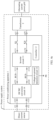
- FIG. 3 is a schematic of a structure of a power supply system according to this application.
- the power supply system includes a power conditioning apparatus 1, a transformer 2, and a controller 13.
- the power conditioning apparatus 1 includes direct current input ends i11 and i12, an inverter circuit 11, a voltage-to-ground detector 12, a grid-connected switch K1, and an alternating current output end o11.
- the direct current input ends i11 and i12 of the power conditioning apparatus 1 are configured to connect to a positive electrode and a negative electrode of a direct current source respectively.
- the direct current source includes a photovoltaic string or a battery cluster.
- the alternating current output end o11 of the power conditioning apparatus 1 is configured to connect to an input end of the transformer 2, and an output end of the transformer 2 is configured to connect to an alternating current power grid.
- An end of the inverter circuit 11, namely, direct current input ends i111 and i 112 of the inverter circuit 11 are configured to connect to the direct current input ends i11 and i 12 of the power conditioning apparatus 1 respectively.
- Another end of the inverter circuit 11, namely, an alternating current output end ⁇ 111 of the inverter circuit 11 is configured to connect to the alternating current output end o11 of the power conditioning apparatus 1 through the grid-connected switch K1.
- the power conditioning apparatus 1 further includes a neutral wire grid-connected switch KN and a neutral wire output end o 1N.
- the inverter circuit 11 further includes a neutral wire output end o11N.
- the neutral wire output end o11N of the inverter circuit 11 is configured to connect to the neutral wire output end ⁇ 1N of the power conditioning apparatus 1 through the neutral wire grid-connected switch KN.
- the neutral wire output end o1N of the power conditioning apparatus 1 is configured to connect to the input end of the transformer 2.
- a is connected to B may be that A is directly connected to B or A is indirectly connected to B through C.
- the direct current input end of the inverter circuit 11 may be directly connected to the direct current input end of the power conditioning apparatus 1.
- the power conditioning apparatus 1 further includes a DC/DC conversion circuit
- the direct current input end of the inverter circuit 11 may be indirectly connected to the direct current input end of the power conditioning apparatus 1 through the DC/DC conversion circuit.
- the voltage-to-ground detector 12 detects a voltage to ground of the power conditioning apparatus 1 to obtain a first voltage value; and when the grid-connected switch K1 is turned on, the voltage-to-ground detector 12 detects the voltage to ground of the power conditioning apparatus 1 to obtain a second voltage value. Then, the controller 13 obtains the first voltage value and the second voltage value through the voltage-to-ground detector 12.
- the controller 13 When a difference between the second voltage value and the first voltage value falls within a preset voltage range, which indicates that a neutral wire of the transformer 2 is grounded, that is, the neutral wire of the transformer 2 is connected to a reference ground PE, the controller 13 outputs alarm information for grounding of the neutral wire of the transformer 2, or the controller 13 controls the power conditioning apparatus 1 to stop working, that is, the controller 13 stops working. That the controller 13 stops working means that the controller 13 is powered on but no longer outputs a control signal.
- a difference that is between the second voltage value and the first voltage value and that exists when the neutral wire of the transformer 2 is grounded varies greatly from a difference that is between the second voltage value and the first voltage value and that exists when the neutral wire of the transformer 2 is not grounded. Therefore, the power supply system can effectively determine, based on a magnitude relationship between two voltage to ground values that are of the power conditioning apparatus 1 and that are obtained by the voltage-to-ground detector 12 through detection before and after an action of the grid-connected switch K1, whether the neutral wire of the transformer 2 is grounded. This detection manner is simple and helps improve detection efficiency.
- the power conditioning apparatus 1 when the neutral wire of the transformer 2 is grounded, the power conditioning apparatus 1 outputs the alarm information for grounding of the neutral wire of the transformer 2 or stops working, to prompt an operator to check for a neutral wire grounding fault of the transformer 2 in time to ensure that the neutral wire of the transformer 2 is no longer grounded.
- This can avoid a case in which a fault current damages a device due to grounding of the neutral wire of the transformer 2 when a short circuit to ground occurs in a power transmission path on which the power conditioning apparatus 1 is located, to improve reliability of the power conditioning apparatus 1 and therefore improve reliability of the power supply system. Because the voltage-to-ground detector 12 and the grid-connected switch K1 are both existing circuit components in the power conditioning apparatus 1, no additional circuit component is required in this detection manner, and detection costs can be reduced.
- the controller in the power supply system may be a system controller independent of the power conditioning apparatus 1 and the transformer 2, or may be a controller located inside the power conditioning apparatus 1. This is not limited in this application. Regardless of whether the controller in the power supply system is the system controller or the controller inside the power conditioning apparatus 1, working principles of the power supply system are the same. Therefore, for ease of description, the following uses an example in which the controller in the power supply system is the controller inside the power conditioning apparatus 1 for description.
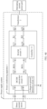
- FIG. 4a is a schematic of another structure of a power supply system according to this application.
- a power conditioning apparatus 1 shown in FIG. 4a further includes a direct current bus and a DC/DC conversion circuit 14.
- Direct current input ends of an inverter circuit 11 are connected to an end of the DC/DC conversion circuit 14 (namely, direct current output ends of the DC/DC conversion circuit 14) through the direct current bus.
- Another end of the DC/DC conversion circuit 14 (namely, direct current input ends of the DC/DC conversion circuit 14) is connected to direct current input ends of the power conditioning apparatus 1.
- the direct current bus includes a positive direct current bus BUS+ and a negative direct current bus BUS-.
- a direct current input end i111 of the inverter circuit 11 is connected to a direct current output end o121 of the DC/DC conversion circuit 14 through the positive direct current bus BUS+.
- a direct current input end i112 of the inverter circuit 11 is connected to a direct current output end o122 of the DC/DC conversion circuit 14 through the negative direct current bus BUS-.
- Direct current input ends i121 and i122 of the DC/DC conversion circuit 14 are connected to direct current input ends i11 and i12 of the power conditioning apparatus 1 respectively.
- a voltage-to-ground detector 12 is connected between a reference ground PE and an alternating current output end ⁇ 111 of the inverter circuit 11 connected to a grid-connected switch K1.
- the voltage-to-ground detector 12 is any voltage detection circuit that can measure both an alternating current voltage and a direct current voltage, for example, a voltmeter or a voltage divider circuit.
- a controller 13 controls the grid-connected switch K1 to be turned off, and sends a sampling control signal to the voltage-to-ground detector 12.
- the voltage-to-ground detector 12 collects a voltage to ground of the power conditioning apparatus 1, namely, a voltage between the alternating current output end o111 of the inverter circuit 11 and the reference ground PE to obtain a first voltage value, and sends the first voltage value to the controller 13.
- the controller 13 controls the grid-connected switch K1 to be turned on, and sends a sampling control signal to the voltage-to-ground detector 12.
- the voltage-to-ground detector 12 collects the voltage between the alternating current output end o111 of the inverter circuit 11 and the reference ground PE to obtain a second voltage value, and sends the second voltage value to the controller 13.
- the controller 13 After the controller 13 receives the first voltage value and the second voltage value that are sent by the voltage-to-ground detector 12, when a difference between the second voltage value and the first voltage value is greater than a first voltage threshold, which indicates that a neutral wire of the transformer 2 is grounded, the controller 13 stops working, to cause the power conditioning apparatus 1 to be in a sleep state. In this way, an operator is prompted to check for a fault in time.
- the controller 13 when the difference between the second voltage value and the first voltage value is greater than the first voltage threshold, the controller 13 outputs alarm information for grounding of the neutral wire of the transformer 2, or sends alarm information for grounding of the neutral wire of the transformer 2 to an upper-level device or a terminal device to cause the upper-level device or the terminal device to output, through a display, the alarm information for grounding of the neutral wire of the transformer 2.
- the operator is prompted to take a corresponding protection measure, for example, controlling a switch between the transformer 2 and an alternating current power grid to be turned off or checking for a neutral wire fault of the transformer 2 to ensure that the neutral wire of the transformer 2 is no longer grounded.
- the controller 13 controls the power conditioning apparatus 1 to be started. Specifically, the controller 13 controls both the grid-connected switch K1 and a neutral wire grid-connected switch KN to be turned on, and controls both the DC/DC conversion circuit 14 and the inverter circuit 11 to start to output a voltage.
- the DC/DC conversion circuit 14 nor the inverter circuit 11 starts to work.
- the neutral wire of the transformer 2 is not grounded, regardless of whether the grid-connected switch K1 is turned on or turned off, a loop cannot be formed between the alternating current power grid and the alternating current output end o111.
- the first voltage value and the second voltage value that are obtained by the voltage-to-ground detector 12 are basically the same, and the difference between the second voltage value and the first voltage value is less than or equal to the first voltage threshold.
- the loop cannot be formed between the alternating current power grid and the alternating current output end o111; and when the grid-connected switch K1 is turned on, the loop is formed between the alternating current power grid and the alternating current output end ⁇ 111.
- the first voltage value obtained through detection when the grid-connected switch K1 is turned off is less than the second voltage value obtained through detection when the grid-connected switch K1 is turned on, so that the difference between the second voltage value and the first voltage value is greater than the first voltage threshold.
- the power conditioning apparatus 1 can effectively determine, based on a magnitude relationship between two voltage to ground values that are of the power conditioning apparatus 1 and that are obtained by the voltage-to-ground detector 12 through detection before and after an action of the grid-connected switch K1, whether the neutral wire of the transformer 2 is grounded.
- the voltage-to-ground detector 12 may alternatively be connected between the positive direct current bus BUS+ and the reference ground PE.
- the voltage-to-ground detector 12 may alternatively be connected between the positive direct current bus BUS+ and the reference ground PE.
- a component forming a loop with the alternating current power grid changes from the alternating current output end o111 to the positive direct current bus BUS+ in a detection principle according to which the power conditioning apparatus 1 can effectively determine whether the neutral wire of the transformer 2 is grounded.
- the first voltage value and the second voltage value that are obtained by the voltage-to-ground detector 12 are basically the same, and the difference between the second voltage value and the first voltage value is less than or equal to the first voltage threshold.
- the first voltage value obtained through detection when the grid-connected switch K1 is turned off is less than the second voltage value obtained through detection when the grid-connected switch K1 is turned on, so that the difference between the second voltage value and the first voltage value is greater than the first voltage threshold.
- the voltage-to-ground detector 12 may alternatively be connected between the negative direct current bus BUS- and the reference ground PE.
- the voltage-to-ground detector 12 may alternatively be connected between the negative direct current bus BUS- and the reference ground PE.
- a component forming a loop with the alternating current power grid changes from the alternating current output end o111 to the negative direct current bus BUS- in a detection principle according to which the power conditioning apparatus 1 can effectively determine whether the neutral wire of the transformer 2 is grounded.
- the voltage-to-ground detector 12 may alternatively be connected between the reference ground PE and the direct current input end i11 of the power conditioning apparatus 1.
- the voltage-to-ground detector 12 When the voltage-to-ground detector 12 is connected between the direct current input end i11 and the reference ground PE, a component forming a loop with the alternating current power grid changes from the alternating current output end ⁇ 111 to the direct current input end i11 in a detection principle according to which the power conditioning apparatus 1 can effectively determine whether the neutral wire of the transformer 2 is grounded.
- the voltage-to-ground detector 12 may alternatively be connected between the reference ground PE and the direct current input end i12 of the power conditioning apparatus 1.
- the voltage-to-ground detector 12 may alternatively be connected between the reference ground PE and the direct current input end i12 of the power conditioning apparatus 1.
- a component forming a loop with the alternating current power grid changes from the alternating current output end o111 to the direct current input end i12 in a detection principle according to which the power conditioning apparatus 1 can effectively determine whether the neutral wire of the transformer 2 is grounded.
- the voltage-to-ground detector 12 may alternatively be connected between a bus neutral point BUSN and the reference ground PE.
- the power conditioning apparatus 1 further includes a positive bus capacitor C1 and a negative bus capacitor C2.
- the positive bus capacitor C1 and the negative bus capacitor C2 are connected in series between the positive direct current bus BUS+ and the negative direct current bus BUS-.
- a junction between the positive bus capacitor C1 and the negative bus capacitor C2 forms the bus neutral point BUSN.
- a component forming a loop with the alternating current power grid changes from the alternating current output end o111 to the bus neutral point BUSN in a detection principle according to which the power conditioning apparatus 1 can effectively determine whether the neutral wire of the transformer 2 is grounded.
- the power conditioning apparatus 1 can determine, based on a magnitude relationship between two voltage to ground values that are of the alternating current output end o111 of the inverter circuit 11, the direct current bus, the bus neutral point, or the direct current input end of the power conditioning apparatus 1 and that are obtained by the voltage-to-ground detector 12 through detection before and after an action of the grid-connected switch K1, whether the neutral wire of the transformer 2 is grounded.
- This detection manner is simple and helps improve detection efficiency.
- the voltage-to-ground detector 12 and the grid-connected switch K1 are both existing circuit components in the power conditioning apparatus 1, no additional circuit component is required in this detection manner, and detection costs can be reduced.
- a protection measure is taken in time when the neutral wire of the transformer 2 is grounded, and the power conditioning apparatus 1 is started only when the neutral wire of the transformer 2 is not grounded. This can effectively avoid a case in which a fault current damages the power conditioning apparatus 1 due to grounding of the neutral wire of the transformer 2 when a short circuit to ground occurs in a power transmission path on which the power conditioning apparatus 1 is located, to improve reliability of the power conditioning apparatus 1 and therefore improve reliability of the power supply system.
- FIG. 4g is a schematic of another structure of a power supply system according to this application.
- a voltage-to-ground detector 12 in a power supply system shown in FIG. 4g is connected between a reference ground PE and an alternating current output end o11 of a power conditioning apparatus 1.
- a specific connection relationship between circuits other than the voltage-to-ground detector 12 in the power supply system shown in FIG. 4g refer to descriptions of corresponding parts in the power supply system shown in FIG. 4a . Details are not described herein again.
- a controller 13 controls a grid-connected switch K1 to be turned off or turned on, and obtains a first voltage value and a second voltage value through the voltage-to-ground detector 12.
- the controller 13 obtains the first voltage value and the second voltage value, refer to descriptions of corresponding parts in the power supply system shown in FIG. 4a . Details are not described herein again.
- the controller 13 After the controller 13 receives the first voltage value and the second voltage value that are sent by the voltage-to-ground detector 12, when a difference between the second voltage value and the first voltage value is less than a second voltage threshold, the controller 13 stops working, or outputs alarm information for grounding of a neutral wire of a transformer 2, or sends alarm information for grounding of a neutral wire of a transformer 2 to an upper-level device or a terminal device.
- the controller 13 controls the power conditioning apparatus 1 to be started.
- the ground impedance value that is of the alternating current output end o11 and that exists when the grid-connected switch K1 is turned off is the same as the ground impedance value that is of the alternating current output end o11 and that exists when the grid-connected switch K1 is turned on. Therefore, the first voltage value obtained through detection when the grid-connected switch K1 is turned off and the second voltage value obtained through detection when the grid-connected switch K1 is turned on are basically the same, so that the difference between the second voltage value and the first voltage value is less than the second voltage threshold.
- the power conditioning apparatus 1 can effectively determine, based on a magnitude relationship between two voltage to ground values that are of the power conditioning apparatus 1 and that are obtained by the voltage-to-ground detector 12 through detection before and after an action of the grid-connected switch K1, whether the neutral wire of the transformer 2 is grounded.
- the power conditioning apparatus 1 can determine, based on a magnitude relationship between two voltage to ground values that are of the alternating current output end o11 and that are obtained by the voltage-to-ground detector 12 through detection before and after an action of the grid-connected switch K1, whether the neutral wire of the transformer 2 is grounded.
- This detection manner is simple and helps improve detection efficiency.
- the voltage-to-ground detector 12 and the grid-connected switch K1 are both existing circuit components in the power conditioning apparatus 1, no additional circuit component is required in this detection manner, and detection costs can be reduced.
- a protection measure is taken in time when the neutral wire of the transformer 2 is grounded, and the power conditioning apparatus 1 is started only when the neutral wire of the transformer 2 is not grounded.
- the power conditioning apparatus 1 provided in this application may be a three-phase power conditioning apparatus other than the single-phase power conditioning apparatuses shown in FIG. 3 to FIG. 4g .
- a power conditioning apparatus 1 in a power supply system shown in FIG. 5 to FIG. 6g refer to a power conditioning apparatus 1 in a power supply system shown in FIG. 5 to FIG. 6g .
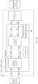
- FIG. 5 is a schematic of another structure of a power supply system according to this application.
- a power conditioning apparatus 1 shown in FIG. 5 further includes an alternating current output end o12, an alternating current output end o13, a grid-connected switch K2, and a grid-connected switch K3.
- Another end of an inverter circuit 11 further includes an alternating current output end ⁇ 112 and an alternating current output end o113.
- the alternating current output end o112 of the inverter circuit 11 is connected to the alternating current output end o12 of the power conditioning apparatus 1 through the grid-connected switch K2.
- the alternating current output end o113 of the inverter circuit 11 is connected to the alternating current output end o13 of the power conditioning apparatus 1 through the grid-connected switch K3.
- the alternating current output end o12 and the alternating current output end o13 of the power conditioning apparatus 1 are connected to an input end of a transformer 2.
- a transformer 2 for a specific connection relationship of parts in the power supply system shown in FIG. 5 other than the output end of the inverter circuit 11 and the output end of the power conditioning apparatus 1, refer to descriptions of corresponding parts in the power supply system shown in FIG. 3 . Details are not described herein again.
- a voltage-to-ground detector 12 detects a voltage to ground of the power conditioning apparatus 1 to obtain a first voltage value; and when the grid-connected switch K1 is turned on, the voltage-to-ground detector 12 detects the voltage to ground of the power conditioning apparatus 1 to obtain a second voltage value. Then, a controller 13 obtains the first voltage value and the second voltage value through the voltage-to-ground detector 12. The controller 13 outputs alarm information for grounding of a neutral wire of the transformer 2 or stops working when a difference between the second voltage value and the first voltage value falls within a preset voltage range.
- the power conditioning apparatus 1 can determine, based on a magnitude relationship between two voltage to ground values that are of the power conditioning apparatus 1 and that are obtained by the voltage-to-ground detector 12 through detection before and after an action of the grid-connected switch K1, whether the neutral wire of the transformer 2 is grounded. This detection manner is simple and helps improve detection efficiency.
- the voltage-to-ground detector 12 and the grid-connected switch K1 are both existing circuit components in the power conditioning apparatus 1, no additional circuit component is required in this detection manner, and detection costs can be reduced.
- a protection measure is taken on the power conditioning apparatus 1 in time when the neutral wire of the transformer 2 is grounded. This can effectively avoid a case in which a fault current damages the power conditioning apparatus 1 due to grounding of the neutral wire of the transformer 2 when a short circuit to ground occurs in a power transmission path on which the power conditioning apparatus 1 is located, to improve reliability of the power conditioning apparatus 1 and therefore improve reliability of the power supply system.
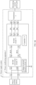
- FIG. 6a is a schematic of another structure of a power supply system according to this application.
- a power conditioning apparatus 1 shown in FIG. 6a compared with the power conditioning apparatus 1 shown in FIG. 4a , a power conditioning apparatus 1 shown in FIG. 6a further includes an alternating current output end o12, an alternating current output end o13, a grid-connected switch K2, and a grid-connected switch K3.
- Another end of an inverter circuit 11 further includes an alternating current output end o112 and an alternating current output end o113.
- the output end of the inverter circuit 11 and the output end of the power conditioning apparatus 1 shown in FIG. 6a refer to descriptions of corresponding parts in the power supply system shown in FIG. 5 . Details are not described herein again.
- a controller 13 controls a grid-connected switch K1 to be turned off or turned on, and obtains a first voltage value and a second voltage value through a voltage-to-ground detector 12.
- the controller 13 obtains the first voltage value and the second voltage value, refer to descriptions of corresponding parts in the power supply system shown in FIG. 4a . Details are not described herein again.
- the controller 13 After the controller 13 receives the first voltage value and the second voltage value that are sent by the voltage-to-ground detector 12, when a difference between the second voltage value and the first voltage value is less than a second voltage threshold, the controller 13 outputs alarm information for grounding of a neutral wire of a transformer 2, or sends alarm information for grounding of a neutral wire of a transformer 2 to an upper-level device or a terminal device, or stops working.
- the controller 13 controls the power conditioning apparatus 1 to be started.
- the voltage-to-ground detector 12 may alternatively be connected between a positive direct current bus BUS+ and a reference ground PE.
- a positive direct current bus BUS+ refers to a power supply system shown in FIG. 6b .
- the voltage-to-ground detector 12 may alternatively be connected between a negative direct current bus BUS- and the reference ground PE.
- a power supply system shown in FIG. 6c refers to a power supply system shown in FIG. 6c .
- the voltage-to-ground detector 12 may alternatively be connected between the reference ground PE and a direct current input end i11 of the power conditioning apparatus 1.
- a power supply system shown in FIG. 6d refers a power supply system shown in FIG. 6d .
- the voltage-to-ground detector 12 may alternatively be connected between the reference ground PE and a direct current input end i12 of the power conditioning apparatus 1.
- a power supply system shown in FIG. 6e refers to a power supply system shown in FIG. 6e .
- the voltage-to-ground detector 12 may alternatively be connected between a bus neutral point BUSN of the power conditioning apparatus 1 and the reference ground PE.
- a power supply system shown in FIG. 6f refer to a power supply system shown in FIG. 6f .
- the power supply systems shown in FIG. 6a to FIG. 6f may effectively determine whether a neutral wire of the transformer 2 is grounded. Refer to descriptions of corresponding parts in the power supply systems shown in FIG. 4a to FIG. 4f . Details are not described herein again.
- the power conditioning apparatus 1 can determine, based on a magnitude relationship between two voltage to ground values that are of the alternating current output end o111 of the inverter circuit 11, the direct current bus, the bus neutral point, or the direct current input end of the power conditioning apparatus 1 and that are obtained by the voltage-to-ground detector 12 through detection before and after an action of the grid-connected switch K1, whether the neutral wire of the transformer 2 is grounded.
- This detection manner is simple and helps improve detection efficiency.
- the voltage-to-ground detector 12 and the grid-connected switch K1 are both existing circuit components in the power conditioning apparatus 1, no additional circuit component is required in this detection manner, and detection costs can be reduced.
- a protection measure is taken in time when the neutral wire of the transformer 2 is grounded, and the power conditioning apparatus 1 is started only when the neutral wire of the transformer 2 is not grounded. This can effectively avoid a case in which a fault current damages the power conditioning apparatus 1 due to grounding of the neutral wire of the transformer 2 when a short circuit to ground occurs in a power transmission path on which the power conditioning apparatus 1 is located, to improve reliability of the power conditioning apparatus 1 and therefore improve reliability of the power supply system.
- FIG. 6g is a schematic of another structure of a power supply system according to this application.
- a voltage-to-ground detector 12 in a power supply system shown in FIG. 6g is connected between a reference ground PE and an alternating current output end o11 of a power conditioning apparatus 1.
- a specific connection relationship between circuits other than the voltage-to-ground detector 12 in the power supply system shown in FIG. 6g refer to descriptions of corresponding parts in the power supply system shown in FIG. 6a . Details are not described herein again.
- a controller 13 controls a grid-connected switch K1 to be turned off or turned on, and obtains a first voltage value and a second voltage value through the voltage-to-ground detector 12.
- the controller 13 obtains the first voltage value and the second voltage value, refer to descriptions of corresponding parts in the power supply system shown in FIG. 4a . Details are not described herein again.
- the controller 13 After the controller 13 receives the first voltage value and the second voltage value that are sent by the voltage-to-ground detector 12, when a difference between the second voltage value and the first voltage value is less than a second voltage threshold, the controller 13 outputs alarm information for grounding of a neutral wire of a transformer 2, or sends alarm information for grounding of a neutral wire of a transformer 2 to an upper-level device or a terminal device, or stops working.
- the controller 13 controls the power conditioning apparatus 1 to be started.
- the power supply systems shown in FIG. 6g may effectively determine whether a neutral wire of the transformer 2 is grounded. Refer to descriptions of corresponding parts in the power supply systems shown in FIG. 4g . Details are not described herein again.
- the power conditioning apparatus 1 can determine, based on a magnitude relationship between two voltage to ground values that are of the alternating current output end o11 and that are obtained by the voltage-to-ground detector 12 through detection before and after an action of the grid-connected switch K1, whether the neutral wire of the transformer 2 is grounded.
- This detection manner is simple and helps improve detection efficiency.
- the voltage-to-ground detector 12 and the grid-connected switch K1 are both existing circuit components in the power conditioning apparatus 1, no additional circuit component is required in this detection manner, and detection costs can be reduced.
- a protection measure is taken in time when the neutral wire of the transformer 2 is grounded, and the power conditioning apparatus 1 is started only when the neutral wire of the transformer 2 is not grounded.
- the power supply systems shown in FIG. 5 to FIG. 6g are all described by using an example in which the grid-connected switch is K1.
- the grid-connected switch may alternatively be K2 or K3.
- the grid-connected switch is K2
- the alternating current output end of the power conditioning apparatus 1 changes from o11 to o12
- the alternating current output end of the inverter circuit 11 changes from o111 to o112.
- the grid-connected switch is K3
- the alternating current output end of the power conditioning apparatus 1 changes from o11 to o13
- the alternating current output end of the inverter circuit 11 changes from o111 to o113.
- a working principle of a power supply system when the grid-connected switch is K2 or K3 is the same as a working principle of the power supply system when the grid-connected switch is K1. Details are not described herein again.
- Working principles of the power supply systems shown in FIG. 4a to FIG. 4g and FIG. 6a to FIG. 6g are also applicable to a power supply system in which the power conditioning apparatus does not include the DC/DC conversion circuit 14. Details are not displayed and described herein again.
- the first voltage value and the second voltage value in this application include a direct current voltage component or an alternating current voltage component.
- FIG. 7 is a schematic of a structure of a power conditioning system according to this application.
- the power conditioning system includes a power conditioning apparatus 1 and a voltage-to-ground detector 12.
- the power conditioning apparatus 1 shown in FIG. 7 does not include the voltage-to-ground detector 12, and the power conditioning apparatus 1 further includes a voltage detection end det1.
- the voltage-to-ground detector 12 is connected between the voltage detection end det1 and a reference ground PE.
- the voltage-to-ground detector 12 is configured to: when a grid-connected switch K1 is turned off, detect a voltage to ground of the voltage detection end det1 to obtain a first voltage value; and when the grid-connected switch K1 is turned on, detect a voltage to ground of the voltage detection end det1 to obtain a second voltage value.
- the voltage detection end det1 is connected to an alternating current output end o111 of an inverter circuit 11, corresponding to a structure in which the voltage-to-ground detector 12 is located outside the power conditioning apparatus 1 in the power supply system shown in FIG. 4a and FIG. 6a .
- the voltage detection end det1 is connected to a positive direct current bus BUS+, corresponding to a structure in which the voltage-to-ground detector 12 is located outside the power conditioning apparatus 1 in the power supply system shown in FIG. 4b and FIG. 6b .
- the voltage detection end det1 is connected to a negative direct current bus BUS-, corresponding to a structure in which the voltage-to-ground detector 12 is located outside the power conditioning apparatus 1 in the power supply system shown in FIG.
- the voltage detection end det1 is a direct current input end i11, corresponding to a structure in which the voltage-to-ground detector 12 is located outside the power conditioning apparatus 1 in the power supply system shown in FIG. 4d and FIG. 6d .
- the voltage detection end det1 is a direct current input end i12, corresponding to a structure in which the voltage-to-ground detector 12 is located outside the power conditioning apparatus 1 in the power supply system shown in FIG. 4e and FIG. 6e .
- the voltage detection end det1 is connected to a bus neutral point, corresponding to a structure in which the voltage-to-ground detector 12 is located outside the power conditioning apparatus 1 in the power supply system shown in FIG. 4f and FIG.
- the voltage detection end det1 is an alternating current output end o11 of the power conditioning apparatus 1, corresponding to a structure in which the voltage-to-ground detector 12 is located outside the power conditioning apparatus 1 in the power supply system shown in FIG. 4g and FIG. 6g .
- a difference that is between the second voltage value and the first voltage value and that exists when a neutral wire of a transformer 2 is grounded varies greatly from a difference that is between the second voltage value and the first voltage value and that exists when the neutral wire of the transformer 2 is not grounded. Therefore, the power conditioning system can effectively determine, based on a magnitude relationship between two voltage to ground values that are of the voltage detection end det1 and that are obtained by the voltage-to-ground detector 12 through detection before and after an action of the grid-connected switch K1, whether the neutral wire of the transformer 2 is grounded. This detection manner is simple and helps improve detection efficiency.
- a protection measure is taken in time when the neutral wire of the transformer 2 is grounded, and the power conditioning apparatus 1 is started only when the neutral wire of the transformer 2 is not grounded. This can effectively avoid a case in which a fault current damages the power conditioning system due to grounding of the neutral wire of the transformer 2 when a short circuit to ground occurs in a power transmission path on which the power conditioning apparatus 1 is located, to improve reliability of the power conditioning system.
- this application further provides a power supply system.
- the power supply system includes a power conditioning system and a transformer 2.
- a connection relationship between the power conditioning system and the transformer 2, and a working principle of the power conditioning system refer to descriptions of corresponding parts in embodiment shown in FIG. 7 . Details are not described herein again.
- a difference that is between a second voltage value and a first voltage value and that exists when a neutral wire of the transformer 2 is grounded varies greatly from a difference that is between the second voltage value and the first voltage value and that exists when the neutral wire of the transformer 2 is not grounded. Therefore, the power conditioning system can effectively determine, based on a magnitude relationship between two voltage to ground values that are of the voltage detection end det1 and that are obtained by the voltage-to-ground detector 12 through detection before and after an action of a grid-connected switch, whether the neutral wire of the transformer 2 is grounded. This detection manner is simple and helps improve detection efficiency.
- a protection measure is taken in time when the neutral wire of the transformer 2 is grounded, and the power conditioning apparatus 1 is started only when the neutral wire of the transformer 2 is not grounded. This can effectively avoid a case in which a fault current damages the power supply system due to grounding of the neutral wire of the transformer 2 when a short circuit to ground occurs in a power transmission path on which the power conditioning apparatus 1 is located, to improve reliability of the power supply system.
Landscapes
- Engineering & Computer Science (AREA)
- Power Engineering (AREA)
- Physics & Mathematics (AREA)
- General Physics & Mathematics (AREA)
- Inverter Devices (AREA)
- Supply And Distribution Of Alternating Current (AREA)
Abstract
This application provides a power supply system, a power conditioning apparatus, and a power conditioning system. The power supply system includes a power conditioning apparatus, a transformer, and a controller. The power conditioning apparatus includes a direct current input end, an inverter circuit, at least one grid-connected switch, a voltage-to-ground detector, and at least one alternating current output end. An end of the inverter circuit is configured to connect to the direct current input end, another end of the inverter circuit is configured to connect to the at least one alternating current output end through the at least one grid-connected switch, and the at least one alternating current output end is configured to connect to a power grid through the transformer. When one grid-connected switch is turned off and turned on, the voltage-to-ground detector detects voltage to grounds of the power conditioning apparatus to obtain a first voltage value and a second voltage value respectively. The controller outputs alarm information for grounding of a neutral wire of the transformer or controls the power conditioning apparatus to stop working when a difference between the second voltage value and the first voltage value falls within a preset voltage range. According to this application, reliability of the power supply system can be improved.
Description
- This application relates to the field of power supply technologies, and in particular, to a power supply system, a power conditioning apparatus, and a power conditioning system.
- In a process of installing a photovoltaic system shown in
FIG. 1 , an operator may mistakenly connect a neutral N wire of a transformer in the photovoltaic system to a reference ground PE, incurring a risk of damage to the photovoltaic system in a running process. Specifically, in a case in which the neutral N wire of the transformer is connected to the reference ground PE, after a short circuit to ground occurs in a power transmission path of the photovoltaic system (for example, a power transmission path formed by a photovoltaic string, an inverter, and a transformer shown inFIG. 1 ), for example, a short circuit to ground occurs in the photovoltaic string, and a relay inside the inverter is turned on, a large fault current is generated in the power transmission path, and the fault current may damage a circuit in the power transmission path, for example, the inverter. Therefore, how to detect a status of connection between the neutral N wire of the transformer and the reference ground PE, and take a protection measure in time when it is detected that the neutral N wire of the transformer is connected to the reference ground PE is particularly important. - This application provides a power supply system, a power conditioning apparatus, and a power conditioning system. This can effectively determine a status of connection between a neutral wire of a transformer and a reference ground, and take a protection measure in time when the neutral wire of the transformer is grounded, to improve reliability of the power supply system.
- According to a first aspect, this application provides a power supply system. The power supply system includes a power conditioning apparatus, a transformer, and a controller. The power conditioning apparatus includes a direct current input end, an inverter circuit, at least one grid-connected switch, a voltage-to-ground detector, and at least one alternating current output end. The direct current input end of the power conditioning apparatus is configured to connect to a direct current source. An end of the inverter circuit is configured to connect to the direct current input end, and another end of the inverter circuit is configured to connect to the at least one alternating current output end of the power conditioning apparatus through the at least one grid-connected switch. The at least one alternating current output end of the power conditioning apparatus is configured to connect to an input end of the transformer, and an output end of the transformer is configured to connect to a power grid. When one of the at least one grid-connected switch is turned off, the voltage-to-ground detector detects a voltage to ground of the power conditioning apparatus to obtain a first voltage value; and when the grid-connected switch is turned on, the voltage-to-ground detector detects the voltage to ground of the power conditioning apparatus to obtain a second voltage value. Then the controller outputs alarm information for grounding of a neutral wire of the transformer or controls the power conditioning apparatus to stop working when a difference between the second voltage value and the first voltage value falls within a preset voltage range.
- In this implementation, a difference that is between the second voltage value and the first voltage value and that exists when the neutral wire of the transformer is grounded varies greatly from a difference that is between the second voltage value and the first voltage value and that exists when the neutral wire of the transformer is not grounded. Therefore, the power supply system can effectively determine, based on a magnitude relationship between two voltage to ground values that are of the power conditioning apparatus and that are obtained by the voltage-to-ground detector through detection before and after an action of the grid-connected switch (for example, a first grid-connected switch), whether the neutral wire of the transformer is grounded. This detection manner is simple and helps improve detection efficiency. In addition, when the neutral wire of the transformer is grounded, the power conditioning apparatus outputs the alarm information for grounding of the neutral wire of the transformer or stops working, to prompt an operator to check for a neutral wire grounding fault of the transformer in time to ensure that the neutral wire of the transformer is no longer grounded. This can avoid a case in which a fault current damages a device due to grounding of the neutral wire of the transformer when a short circuit to ground occurs in a power transmission path on which the power conditioning apparatus is located, to improve reliability of the power conditioning apparatus and therefore improve reliability of the power supply system.
- With reference to the first aspect, in a first possible implementation, the voltage-to-ground detector is connected between a reference ground and the another end of the inverter circuit connected to the grid-connected switch. When the difference between the second voltage value and the first voltage value is greater than a first voltage threshold, the controller outputs the alarm information for grounding of the neutral wire of the transformer or controls the power conditioning apparatus to stop working.
- In this implementation, the power supply system can determine, based on a magnitude relationship between two voltage to ground values that are of the another end of the inverter circuit connected to the first grid-connected switch and that are obtained by the voltage-to-ground detector through detection before and after an action of the first grid-connected switch, whether the neutral wire of the transformer is grounded. This detection manner is simple and helps improve detection efficiency. In addition, when the neutral wire of the transformer is grounded, the power conditioning apparatus outputs the alarm information for grounding of the neutral wire of the transformer or stops working, to prompt the operator to check for the neutral wire grounding fault of the transformer in time to ensure that the neutral wire of the transformer is no longer grounded. In this way, the reliability of the power conditioning apparatus can be improved. Therefore, the reliability of the power supply system is improved.
- With reference to the first aspect, in a second possible implementation, the voltage-to-ground detector is connected between a reference ground and one alternating current output end connected to the grid-connected switch. When the difference between the second voltage value and the first voltage value is less than a second voltage threshold, the controller outputs the alarm information for grounding of the neutral wire of the transformer or controls the power conditioning apparatus to stop working.
- In this implementation, a position of the voltage-to-ground detector changes from a left side of the first grid-connected switch to a right side. A detection manner in which the power supply system detects, when the voltage-to-ground detector is located on the right side of the first grid-connected switch, whether the neutral wire of the transformer is grounded is opposite to a detection manner in which the power supply system detects, when the voltage-to-ground detector is located on the left side of the first grid-connected switch, whether the neutral wire of the transformer is grounded. There are various detection manners of the power supply system, and flexibility is high. In addition, when the neutral wire of the transformer is grounded, the power conditioning apparatus outputs the alarm information for grounding of the neutral wire of the transformer or stops working, to prompt the operator to check for the neutral wire grounding fault of the transformer in time to ensure that the neutral wire of the transformer is no longer grounded. In this way, the reliability of the power conditioning apparatus can be improved. Therefore, the reliability of the power supply system is improved.
- With reference to the first aspect, in a third possible implementation, the power conditioning apparatus further includes a direct current bus. The end of the inverter circuit is connected to the direct current input end of the power conditioning apparatus through the direct current bus. The voltage-to-ground detector is connected between the direct current bus and a reference ground. When the difference between the second voltage value and the first voltage value is greater than a first voltage threshold, the controller outputs the alarm information for grounding of the neutral wire of the transformer or controls the power conditioning apparatus to stop working.
- In this implementation, the power supply system can determine, based on a magnitude relationship between two voltage to ground values that are of the direct current bus and that are obtained by the voltage-to-ground detector through detection before and after an action of the first grid-connected switch, whether the neutral wire of the transformer is grounded. This detection manner is simple and helps improve detection efficiency. In addition, when the neutral wire of the transformer is grounded, the power conditioning apparatus outputs the alarm information for grounding of the neutral wire of the transformer or stops working, to prompt the operator to check for the neutral wire grounding fault of the transformer in time to ensure that the neutral wire of the transformer is no longer grounded. In this way, the reliability of the power conditioning apparatus can be improved. Therefore, the reliability of the power supply system is improved.
- With reference to the first aspect, in a fourth possible implementation, the power conditioning apparatus further includes a positive direct current bus, a negative direct current bus, a positive bus capacitor, and a negative bus capacitor. The end of the inverter circuit is connected to the direct current input end of the power conditioning apparatus through the positive direct current bus and the negative direct current bus separately. The positive bus capacitor and the negative bus capacitor are connected in series between the positive direct current bus and the negative direct current bus. The voltage-to-ground detector is connected between a bus neutral point and a reference ground. The bus neutral point is a junction between the positive bus capacitor and the negative bus capacitor. When the difference between the second voltage value and the first voltage value is greater than a first voltage threshold, the controller outputs the alarm information for grounding of the neutral wire of the transformer or controls the power conditioning apparatus to stop working.
- In this implementation, the power supply system can determine, based on a magnitude relationship between two voltage to ground values that are of the bus neutral point and that are obtained by the voltage-to-ground detector through detection before and after an action of the first grid-connected switch, whether the neutral wire of the transformer is grounded. This detection manner is simple and helps improve detection efficiency. In addition, when the neutral wire of the transformer is grounded, the power conditioning apparatus outputs the alarm information for grounding of the neutral wire of the transformer or stops working, to prompt the operator to check for the neutral wire grounding fault of the transformer in time to ensure that the neutral wire of the transformer is no longer grounded. In this way, the reliability of the power conditioning apparatus can be improved. Therefore, the reliability of the power supply system is improved.
- With reference to the first aspect, in a fifth possible implementation, the voltage-to-ground detector is connected between a reference ground and the direct current input end of the power conditioning apparatus. When the difference between the second voltage value and the first voltage value is greater than a first voltage threshold, the controller outputs the alarm information for grounding of the neutral wire of the transformer or controls the power conditioning apparatus to stop working.
- In this implementation, the power supply system can determine, based on a magnitude relationship between two voltage to ground values that are of the direct current input end of the power conditioning apparatus and that are obtained by the voltage-to-ground detector through detection before and after an action of the first grid-connected switch, whether the neutral wire of the transformer is grounded. This detection manner is simple and helps improve detection efficiency. In addition, when the neutral wire of the transformer is grounded, the power conditioning apparatus outputs the alarm information for grounding of the neutral wire of the transformer or stops working, to prompt the operator to check for the neutral wire grounding fault of the transformer in time to ensure that the neutral wire of the transformer is no longer grounded. In this way, the reliability of the power conditioning apparatus can be improved. Therefore, the reliability of the power supply system is improved.
- With reference to any one of the first aspect to the fifth possible implementation of the first aspect, in a sixth possible implementation, the controller further controls, before the power conditioning apparatus is started, the grid-connected switch to be turned off or turned on, so that the voltage-to-ground detector obtains the first voltage value or the second voltage value through detection.
- In this embodiment, the power supply system detects, before the power conditioning apparatus is started, whether the neutral wire of the transformer is grounded, to take a corresponding measure based on a detection result. For example, the power conditioning apparatus is started only when it is determined that the neutral wire of the transformer is not grounded. This can effectively avoid a case in which a fault current damages the power conditioning apparatus due to grounding of the neutral wire of the transformer when a short circuit to ground occurs in a power transmission path on which the power conditioning apparatus is located, to improve the reliability of the power conditioning apparatus and therefore improve the reliability of the power supply system.
- With reference to any one of the first aspect to the sixth possible implementation of the first aspect, in a seventh possible implementation, the controller further controls, when the difference between the second voltage value and the first voltage value does not fall within the preset voltage range, the power conditioning apparatus to be started.
- In this implementation, the power conditioning apparatus is started only when it is determined that the neutral wire of the transformer is not grounded. This can effectively avoid a case in which a fault current damages the power conditioning apparatus due to grounding of the neutral wire of the transformer when a short circuit to ground occurs in a power transmission path on which the power conditioning apparatus is located, to improve the reliability of the power conditioning apparatus and therefore improve the reliability of the power supply system.
- With reference to any one of the first aspect to the seventh possible implementation of the first aspect, in an eighth possible implementation, the power conditioning apparatus further includes a DC/DC conversion circuit and the direct current bus. The end of the inverter circuit is connected to an end of the DC/DC conversion circuit through the direct current bus, and another end of the DC/DC conversion circuit is connected to the direct current input end of the power conditioning apparatus.
- In this implementation, the power conditioning apparatus may further include the DC/DC conversion circuit and the direct current bus. There are various functions and circuit structures, and flexibility is high.
- According to a second aspect, this application provides a power conditioning apparatus. The power conditioning apparatus includes a direct current input end, an inverter circuit, at least one grid-connected switch, a controller, a voltage-to-ground detector, and at least one alternating current output end. The direct current input end of the power conditioning apparatus is configured to connect to a direct current source. An end of the inverter circuit is configured to connect to the direct current input end, and another end of the inverter circuit is configured to connect to the at least one alternating current output end of the power conditioning apparatus through the at least one grid-connected switch. The at least one alternating current output end of the power conditioning apparatus is configured to connect to a transformer. When one of the at least one grid-connected switch is turned off, the voltage-to-ground detector detects a voltage to ground of the power conditioning apparatus to obtain a first voltage value; and when the grid-connected switch is turned on, the voltage-to-ground detector detects the voltage to ground of the power conditioning apparatus to obtain a second voltage value. Then the controller outputs alarm information for grounding of a neutral wire of the transformer or controls the power conditioning apparatus to stop working when a difference between the second voltage value and the first voltage value falls within a preset voltage range.
- In this implementation, a difference that is between the second voltage value and the first voltage value and that exists when the neutral wire of the transformer is grounded varies greatly from a difference that is between the second voltage value and the first voltage value and that exists when the neutral wire of the transformer is not grounded. Therefore, the power conditioning apparatus can effectively determine, based on a magnitude relationship between two voltage to ground values that are of the power conditioning apparatus and that are obtained by the voltage-to-ground detector through detection before and after an action of the grid-connected switch (for example, a first grid-connected switch), whether the neutral wire of the transformer is grounded. This detection manner is simple and helps improve detection efficiency. In addition, when the neutral wire of the transformer is grounded, the power conditioning apparatus outputs the alarm information for grounding of the neutral wire of the transformer or stops working, to prompt an operator to check for a neutral wire grounding fault of the transformer in time to ensure that the neutral wire of the transformer is no longer grounded. This can avoid a case in which a fault current damages a device due to grounding of the neutral wire of the transformer when a short circuit to ground occurs in a power transmission path on which the power conditioning apparatus is located. Therefore, reliability of the power conditioning apparatus is improved.
- With reference to the second aspect, in a first possible implementation, the voltage-to-ground detector is connected between a reference ground and the another end of the inverter circuit connected to the grid-connected switch. When the difference between the second voltage value and the first voltage value is greater than a first voltage threshold, the controller outputs the alarm information for grounding of the neutral wire of the transformer or controls the power conditioning apparatus to stop working.
- In this implementation, the power conditioning apparatus can determine, based on a magnitude relationship between two voltage to ground values that are of the another end of the inverter circuit connected to the grid-connected switch and that are obtained by the voltage-to-ground detector through detection before and after an action of the grid-connected switch, whether the neutral wire of the transformer is grounded. This detection manner is simple and helps improve detection efficiency. In addition, when the neutral wire of the transformer is grounded, the power conditioning apparatus outputs the alarm information for grounding of the neutral wire of the transformer or stops working, to prompt the operator to check for the neutral wire grounding fault of the transformer in time to ensure that the neutral wire of the transformer is no longer grounded. Therefore, the reliability of the power conditioning apparatus can be improved.
- With reference to the second aspect, in a second possible implementation, the voltage-to-ground detector is connected between a reference ground and one alternating current output end connected to the grid-connected switch. When the difference between the second voltage value and the first voltage value is less than a second voltage threshold, the controller outputs the alarm information for grounding of the neutral wire of the transformer or controls the power conditioning apparatus to stop working.
- In this implementation, a position of the voltage-to-ground detector changes from a left side of the first grid-connected switch to a right side. A detection manner in which the power conditioning apparatus detects, when the voltage-to-ground detector is located on the right side of the first grid-connected switch, whether the neutral wire of the transformer is grounded is opposite to a detection manner in which the power conditioning apparatus detects, when the voltage-to-ground detector is located on the left side of the first grid-connected switch, whether the neutral wire of the transformer is grounded. There are various detection manners of the power conditioning apparatus, and flexibility is high. In addition, when the neutral wire of the transformer is grounded, the power conditioning apparatus outputs the alarm information for grounding of the neutral wire of the transformer or stops working, to prompt the operator to check for the neutral wire grounding fault of the transformer in time to ensure that the neutral wire of the transformer is no longer grounded. Therefore, the reliability of the power conditioning apparatus can be improved.
- With reference to the second aspect, in a third possible implementation, the power conditioning apparatus further includes a direct current bus. The end of the inverter circuit is connected to the direct current input end of the power conditioning apparatus through the direct current bus. The voltage-to-ground detector is connected between the direct current bus and a reference ground. When the difference between the second voltage value and the first voltage value is greater than a first voltage threshold, the controller outputs the alarm information for grounding of the neutral wire of the transformer or controls the power conditioning apparatus to stop working.
- In this implementation, the power conditioning apparatus can determine, based on a magnitude relationship between two voltage to ground values that are of the direct current bus and that are obtained by the voltage-to-ground detector through detection before and after an action of the first grid-connected switch, whether the neutral wire of the transformer is grounded. This detection manner is simple and helps improve detection efficiency. In addition, when the neutral wire of the transformer is grounded, the power conditioning apparatus outputs the alarm information for grounding of the neutral wire of the transformer or stops working, to prompt the operator to check for the neutral wire grounding fault of the transformer in time to ensure that the neutral wire of the transformer is no longer grounded. Therefore, the reliability of the power conditioning apparatus can be improved.
- With reference to the second aspect, in a fourth possible implementation, the power conditioning apparatus further includes a positive direct current bus, a negative direct current bus, a positive bus capacitor, and a negative bus capacitor. The end of the inverter circuit is connected to the direct current input end of the power conditioning apparatus through the positive direct current bus and the negative direct current bus separately. The positive bus capacitor and the negative bus capacitor are connected in series between the positive direct current bus and the negative direct current bus. The voltage-to-ground detector is connected between a bus neutral point and a reference ground. The bus neutral point is a junction between the positive bus capacitor and the negative bus capacitor. When the difference between the second voltage value and the first voltage value is greater than a first voltage threshold, the controller outputs the alarm information for grounding of the neutral wire of the transformer or controls the power conditioning apparatus to stop working.
- In this implementation, the power conditioning apparatus can determine, based on a magnitude relationship between two voltage to ground values that are of the bus neutral point and that are obtained by the voltage-to-ground detector through detection before and after an action of the first grid-connected switch, whether the neutral wire of the transformer is grounded. This detection manner is simple and helps improve detection efficiency. In addition, when the neutral wire of the transformer is grounded, the power conditioning apparatus outputs the alarm information for grounding of the neutral wire of the transformer or stops working, to prompt the operator to check for the neutral wire grounding fault of the transformer in time to ensure that the neutral wire of the transformer is no longer grounded. Therefore, the reliability of the power conditioning apparatus can be improved.
- With reference to the second aspect, in a fifth possible implementation, the voltage-to-ground detector is connected between a reference ground and the direct current input end of the power conditioning apparatus. When the difference between the second voltage value and the first voltage value is greater than a first voltage threshold, the controller outputs the alarm information for grounding of the neutral wire of the transformer or controls the power conditioning apparatus to stop working.
- In this implementation, the power conditioning apparatus can determine, based on a magnitude relationship between two voltage to ground values that are of the direct current input end of the power conditioning apparatus and that are obtained by the voltage-to-ground detector through detection before and after an action of the first grid-connected switch, whether the neutral wire of the transformer is grounded. This detection manner is simple and helps improve detection efficiency. In addition, when the neutral wire of the transformer is grounded, the power conditioning apparatus outputs the alarm information for grounding of the neutral wire of the transformer or stops working, to prompt the operator to check for the neutral wire grounding fault of the transformer in time to ensure that the neutral wire of the transformer is no longer grounded. Therefore, the reliability of the power conditioning apparatus can be improved.
- With reference to any one of the second aspect to the fifth possible implementation of the second aspect, in a sixth possible implementation, the controller further controls, before the power conditioning apparatus is started, the grid-connected switch to be turned off or turned on, so that the voltage-to-ground detector obtains the first voltage value or the second voltage value through detection.
- In this embodiment, the power supply system detects, before the power conditioning apparatus is started, whether the neutral wire of the transformer is grounded, to take a corresponding measure based on a detection result. For example, the power conditioning apparatus is started only when it is determined that the neutral wire of the transformer is not grounded. This can effectively avoid a case in which a fault current damages the power conditioning apparatus due to grounding of the neutral wire of the transformer when a short circuit to ground occurs in a power transmission path on which the power conditioning apparatus is located, to improve the reliability of the power conditioning apparatus.
- With reference to any one of the second aspect to the sixth possible implementation of the second aspect, in a seventh possible implementation, the controller further controls, when the difference between the second voltage value and the first voltage value does not fall within the preset voltage range, the power conditioning apparatus to be started.
- In this implementation, the power conditioning apparatus is started only when it is determined that the neutral wire of the transformer is not grounded. This can effectively avoid a case in which a fault current damages the power conditioning apparatus due to grounding of the neutral wire of the transformer when a short circuit to ground occurs in a power transmission path on which the power conditioning apparatus is located, to improve the reliability of the power conditioning apparatus.
- With reference to any one of the second aspect to the seventh possible implementation of the second aspect, in an eighth possible implementation, the power conditioning apparatus further includes a DC/DC conversion circuit and the direct current bus. The end of the inverter circuit is connected to an end of the DC/DC conversion circuit through the direct current bus, and another end of the DC/DC conversion circuit is connected to the direct current input end of the power conditioning apparatus.
- In this implementation, the power conditioning apparatus may further include the DC/DC conversion circuit and the direct current bus. There are various functions and circuit structures, and flexibility is high.
- According to a third aspect, this application provides a power conditioning system. The power conditioning system includes a power conditioning apparatus and a voltage-to-ground detector. The power conditioning apparatus includes a direct current input end, an inverter circuit, at least one grid-connected switch, a controller, at least one alternating current output end, and a voltage detection end. The direct current input end of the power conditioning apparatus is configured to connect to a direct current source. An end of the inverter circuit is configured to connect to the direct current input end, and another end of the inverter circuit is configured to connect to the at least one alternating current output end through the at least one grid-connected switch. The at least one alternating current output end is configured to connect to a transformer. The voltage detection end is configured to connect to the voltage-to-ground detector. When one grid-connected switch is turned off, the voltage-to-ground detector detects a voltage to ground of the voltage detection end to obtain a first voltage value; and when the grid-connected switch is turned on, the voltage-to-ground detector detects a voltage to ground of the voltage detection end to obtain a second voltage value. Then the controller outputs alarm information for grounding of a neutral wire of the transformer or controls the power conditioning apparatus to stop working when a difference between the second voltage value and the first voltage value falls within a preset voltage range.
- In this implementation, a difference that is between the second voltage value and the first voltage value and that exists when the neutral wire of the transformer is grounded varies greatly from a difference that is between the second voltage value and a first voltage value and that exists when the neutral wire of the transformer is not grounded. Therefore, the power conditioning apparatus can effectively determine, based on a magnitude relationship between two voltage to ground values that are of the voltage detection end and that are obtained by the voltage-to-ground detector through detection before and after an action of a first grid-connected switch, whether the neutral wire of the transformer is grounded. This detection manner is simple and helps improve detection efficiency. In addition, when the neutral wire of the transformer is grounded, the power conditioning apparatus outputs the alarm information for grounding of the neutral wire of the transformer or stops working, to prompt an operator to check for a neutral wire grounding fault of the transformer in time to ensure that the neutral wire of the transformer is no longer grounded. Therefore, reliability of the power conditioning system can be improved.
- According to a fourth aspect, this application provides a power supply system. The power supply system includes a transformer and the power conditioning system provided in the third aspect. At least one alternating current output end of the power conditioning apparatus is connected to an input end of the transformer, and an output end of the transformer is configured to connect to a power grid.
- In this implementation, a difference that is between a second voltage value and a first voltage value and that exists when a neutral wire of the transformer is grounded varies greatly from a difference that is between the second voltage value and the first voltage value and that exists when the neutral wire of the transformer is not grounded. Therefore, the power conditioning apparatus can effectively determine, based on a magnitude relationship between two voltage to ground values that are of a voltage detection end and that are obtained by a voltage-to-ground detector through detection before and after an action of one grid-connected switch, whether the neutral wire of the transformer is grounded. This detection manner is simple and helps improve detection efficiency. In addition, when the neutral wire of the transformer is grounded, the power conditioning apparatus outputs alarm information for grounding of a neutral wire of the transformer or stops working, to prompt an operator to check for a neutral wire grounding fault of the transformer in time to ensure that the neutral wire of the transformer is no longer grounded. Therefore, reliability of the power supply system can be improved.
-
-
FIG. 1 is a schematic of a structure of a photovoltaic system in the conventional technology; -
FIG. 2 is a schematic of an application scenario of a power supply system according to this application; -
FIG. 3 is a schematic of a structure of a power supply system according to this application; -
FIG. 4a is a schematic of another structure of a power supply system according to this application; -
FIG. 4b is a schematic of another structure of a power supply system according to this application; -
FIG. 4c is a schematic of another structure of a power supply system according to this application; -
FIG. 4d is a schematic of another structure of a power supply system according to this application; -
FIG. 4e is a schematic of another structure of a power supply system according to this application; -
FIG. 4f is a schematic of another structure of a power supply system according to this application; -
FIG. 4g is a schematic of another structure of a power supply system according to this application; -
FIG. 5 is a schematic of another structure of a power supply system according to this application; -
FIG. 6a is a schematic of another structure of a power supply system according to this application; -
FIG. 6b is a schematic of another structure of a power supply system according to this application; -
FIG. 6c is a schematic of another structure of a power supply system according to this application; -
FIG. 6d is a schematic of another structure of a power supply system according to this application; -
FIG. 6e is a schematic of another structure of a power supply system according to this application; -
FIG. 6f is a schematic of another structure of a power supply system according to this application; -
FIG. 6g is a schematic of another structure of a power supply system according to this application; -
FIG. 7 is a schematic of a structure of a power conditioning system according to this application; and -
FIG. 8 is a schematic of another structure of a power supply system according to this application. - The power conditioning apparatus, the power conditioning system, and the power supply system provided in this application are all applicable to a plurality of application fields such as the field of energy storage and power generation, the field of photovoltaic power generation, the field of new energy and smart microgrid, and the field of power transmission and distribution. The power conditioning apparatus provided in this application may be a photovoltaic inverter, a power conversion system (PCS), an uninterruptible power supply (UPS), or the like, and is applicable to different application scenarios, for example, a photovoltaic power supply scenario, an energy storage power supply scenario, a photovoltaic storage hybrid power supply scenario, and a UPS power supply scenario. The following uses the photovoltaic energy storage power supply scenario as an example for description.
-
FIG. 2 is a schematic of an application scenario of a power supply system according to this application. The power supply system provided in this application includes a power conditioning apparatus, a transformer, and a controller. As shown inFIG. 2 , in a photovoltaic energy storage power supply scenario, the power supply system provided in this application is a photovoltaic energy storage power supply system shown inFIG. 2 . The photovoltaic energy storage power supply system includes a photovoltaic string, a DC/DC converter, an inverter, a battery cluster, a power conversion system, two box-type transformer stations, and a step-up substation. The transformer provided in this application is the box-type transformer station shown inFIG. 2 , and the power conditioning apparatus provided in this application is the inverter or the power conversion system shown inFIG. 2 . Regardless of whether the power conditioning apparatus provided in this application is the inverter or the power conversion system, working principles of detecting, by the power conditioning apparatus, whether a neutral wire of the box-type transformer station is grounded are the same. Therefore, for ease of description, the following uses an example in which the power conditioning apparatus is the inverter shown inFIG. 2 for description. The controller provided in this application is a controller in the inverter shown inFIG. 2 . - The inverter includes a direct current input end, an inverter circuit, a voltage-to-ground detector, a grid-connected switch K1, a grid-connected switch K2, a grid-connected switch K3, a controller, and three-phase alternating current output ends. The direct current input end of the inverter is connected to the photovoltaic string through the DC/DC converter, and the three-phase alternating current output ends of the inverter are connected to an input end of one box-type transformer station. A direct current input end of the inverter circuit is connected to the direct current input end of the inverter, three-phase alternating current output ends of the inverter circuit are connected, through the three grid-connected switches (that is, K1 to K3) that are in a one-to-one correspondence with the three-phase alternating current output ends of the inverter circuit, to the three-phase alternating current output ends that are of the inverter and that correspond to the three grid-connected switches. An input end of the power conversion system is connected to the battery cluster, and an output end of the power conversion system is connected to an input end of the other box-type transformer station. Output ends of the two box-type transformer stations are connected in parallel and then connected to an input end of the step-up substation, and an output end of the step-up substation is connected to an alternating current power grid.
- Before the inverter is started, when any one of the three grid-connected switches (for example, the grid-connected switch K1) is turned off, the voltage-to-ground detector detects a voltage to ground of the inverter to obtain a first voltage value; and when the grid-connected switch K1 is turned on, the voltage-to-ground detector detects a voltage to ground of the inverter to obtain a second voltage value. When a difference between the second voltage value and the first voltage value falls within a preset voltage range, which indicates that a neutral wire of the box-type transformer station connected to the three-phase alternating current output ends of the inverter is grounded, the controller outputs alarm information for grounding of a neutral wire of the box-type transformer station or controls the inverter to stop working. In addition, when the difference between the second voltage value and the first voltage value does not fall within the preset voltage range, which indicates that the neutral wire of the box-type transformer station connected to the inverter is not grounded, the controller controls the inverter to be started. Likewise, the power conversion system is also started when a neutral wire of the box-type transformer station connected to the power conversion system is not grounded.
- After the inverter and the power conversion system are started, the photovoltaic energy storage power supply system starts to work. Specifically, the DC/DC converter performs direct current conversion on a direct current generated by the photovoltaic string connected to an input end of the DC/DC converter, and then outputs a direct current to the inverter. The inverter may invert, to an alternating current by controlling the inverter circuit, the direct current that is obtained through direct current conversion and that is input through the input end of the inverter, and output the alternating current to the box-type transformer station connected to the inverter. In addition, the power conversion system inverts, to an alternating current, a direct current output by the battery cluster, and outputs the alternating current to the box-type transformer station connected to the power conversion system. Each box-type transformer station performs voltage step-up on the alternating current input through the input end of the box-type transformer station, and then outputs an alternating current obtained through voltage step-up to the step-up substation. The step-up substation performs voltage step-up on the alternating current input through the input end of the step-up substation, to obtain an alternating current that meets a requirement of the alternating current power grid. Therefore, power is supplied to different types of electric devices such as the alternating current power grid.
- It may be understood that the photovoltaic energy storage power supply system may effectively determine, based on a magnitude relationship between two voltage to ground values that are of the inverter and that are obtained by the voltage-to-ground detector through detection before and after an action of the any one of the three grid-connected switches, whether the neutral wire of the box-type transformer station connected to the inverter is grounded. This detection manner is simple and helps improve detection efficiency. In addition, because the voltage-to-ground detector and the three grid-connected switches are all existing circuit components in the inverter, no additional circuit component is required in this detection manner, and detection costs can be reduced. Besides, the inverter is started only when it is determined that the neutral wire of the box-type transformer station connected to the inverter is not grounded. This can effectively avoid a case in which a fault current damages a device due to grounding of the neutral wire of the box-type transformer station when a short circuit to ground occurs in a power transmission path of the photovoltaic energy storage power supply system. Therefore, reliability of the photovoltaic energy storage power supply system can be improved.
- The foregoing is merely an example of the application scenario of the power supply system provided in this application, but is not exhaustive. The application scenario is not limited in this application.
- With reference to
FIG. 3 to FIG. 8 , the following describes, by using an example, working principles of the power supply system, the power conditioning apparatus, and the power conditioning system provided in this application. -
FIG. 3 is a schematic of a structure of a power supply system according to this application. As shown inFIG. 3 , the power supply system includes apower conditioning apparatus 1, atransformer 2, and acontroller 13. Thepower conditioning apparatus 1 includes direct current input ends i11 and i12, aninverter circuit 11, a voltage-to-ground detector 12, a grid-connected switch K1, and an alternating current output end o11. The direct current input ends i11 and i12 of thepower conditioning apparatus 1 are configured to connect to a positive electrode and a negative electrode of a direct current source respectively. The direct current source includes a photovoltaic string or a battery cluster. The alternating current output end o11 of thepower conditioning apparatus 1 is configured to connect to an input end of thetransformer 2, and an output end of thetransformer 2 is configured to connect to an alternating current power grid. An end of theinverter circuit 11, namely, direct current input ends i111 and i 112 of theinverter circuit 11 are configured to connect to the direct current input ends i11 and i 12 of thepower conditioning apparatus 1 respectively. Another end of theinverter circuit 11, namely, an alternating current output end ο111 of theinverter circuit 11 is configured to connect to the alternating current output end o11 of thepower conditioning apparatus 1 through the grid-connected switch K1. Thepower conditioning apparatus 1 further includes a neutral wire grid-connected switch KN and a neutral wire output end o 1N. Theinverter circuit 11 further includes a neutral wire output end o11N. The neutral wire output end o11N of theinverter circuit 11 is configured to connect to the neutral wire output end ο1N of thepower conditioning apparatus 1 through the neutral wire grid-connected switch KN. The neutral wire output end o1N of thepower conditioning apparatus 1 is configured to connect to the input end of thetransformer 2. - It should be noted that, in this application, that A is connected to B may be that A is directly connected to B or A is indirectly connected to B through C. This is not limited in this application. For example, the direct current input end of the
inverter circuit 11 may be directly connected to the direct current input end of thepower conditioning apparatus 1. Alternatively, when thepower conditioning apparatus 1 further includes a DC/DC conversion circuit, the direct current input end of theinverter circuit 11 may be indirectly connected to the direct current input end of thepower conditioning apparatus 1 through the DC/DC conversion circuit. - In an implementation, when the grid-connected switch K1 is turned off, the voltage-to-
ground detector 12 detects a voltage to ground of thepower conditioning apparatus 1 to obtain a first voltage value; and when the grid-connected switch K1 is turned on, the voltage-to-ground detector 12 detects the voltage to ground of thepower conditioning apparatus 1 to obtain a second voltage value. Then, thecontroller 13 obtains the first voltage value and the second voltage value through the voltage-to-ground detector 12. When a difference between the second voltage value and the first voltage value falls within a preset voltage range, which indicates that a neutral wire of thetransformer 2 is grounded, that is, the neutral wire of thetransformer 2 is connected to a reference ground PE, thecontroller 13 outputs alarm information for grounding of the neutral wire of thetransformer 2, or thecontroller 13 controls thepower conditioning apparatus 1 to stop working, that is, thecontroller 13 stops working. That thecontroller 13 stops working means that thecontroller 13 is powered on but no longer outputs a control signal. - In this embodiment of this application, a difference that is between the second voltage value and the first voltage value and that exists when the neutral wire of the
transformer 2 is grounded varies greatly from a difference that is between the second voltage value and the first voltage value and that exists when the neutral wire of thetransformer 2 is not grounded. Therefore, the power supply system can effectively determine, based on a magnitude relationship between two voltage to ground values that are of thepower conditioning apparatus 1 and that are obtained by the voltage-to-ground detector 12 through detection before and after an action of the grid-connected switch K1, whether the neutral wire of thetransformer 2 is grounded. This detection manner is simple and helps improve detection efficiency. In addition, when the neutral wire of thetransformer 2 is grounded, thepower conditioning apparatus 1 outputs the alarm information for grounding of the neutral wire of thetransformer 2 or stops working, to prompt an operator to check for a neutral wire grounding fault of thetransformer 2 in time to ensure that the neutral wire of thetransformer 2 is no longer grounded. This can avoid a case in which a fault current damages a device due to grounding of the neutral wire of thetransformer 2 when a short circuit to ground occurs in a power transmission path on which thepower conditioning apparatus 1 is located, to improve reliability of thepower conditioning apparatus 1 and therefore improve reliability of the power supply system. Because the voltage-to-ground detector 12 and the grid-connected switch K1 are both existing circuit components in thepower conditioning apparatus 1, no additional circuit component is required in this detection manner, and detection costs can be reduced. - It should be noted that the controller in the power supply system provided in this application may be a system controller independent of the
power conditioning apparatus 1 and thetransformer 2, or may be a controller located inside thepower conditioning apparatus 1. This is not limited in this application. Regardless of whether the controller in the power supply system is the system controller or the controller inside thepower conditioning apparatus 1, working principles of the power supply system are the same. Therefore, for ease of description, the following uses an example in which the controller in the power supply system is the controller inside thepower conditioning apparatus 1 for description. - For example,
FIG. 4a is a schematic of another structure of a power supply system according to this application. As shown inFIG. 4a , compared with thepower conversion apparatus 1 shown inFIG. 3 , apower conditioning apparatus 1 shown inFIG. 4a further includes a direct current bus and a DC/DC conversion circuit 14. Direct current input ends of aninverter circuit 11 are connected to an end of the DC/DC conversion circuit 14 (namely, direct current output ends of the DC/DC conversion circuit 14) through the direct current bus. Another end of the DC/DC conversion circuit 14 (namely, direct current input ends of the DC/DC conversion circuit 14) is connected to direct current input ends of thepower conditioning apparatus 1. Specifically, the direct current bus includes a positive direct current bus BUS+ and a negative direct current bus BUS-. A direct current input end i111 of theinverter circuit 11 is connected to a direct current output end o121 of the DC/DC conversion circuit 14 through the positive direct current bus BUS+. A direct current input end i112 of theinverter circuit 11 is connected to a direct current output end o122 of the DC/DC conversion circuit 14 through the negative direct current bus BUS-. Direct current input ends i121 and i122 of the DC/DC conversion circuit 14 are connected to direct current input ends i11 and i12 of thepower conditioning apparatus 1 respectively. A voltage-to-ground detector 12 is connected between a reference ground PE and an alternating current output end ο111 of theinverter circuit 11 connected to a grid-connected switch K1. The voltage-to-ground detector 12 is any voltage detection circuit that can measure both an alternating current voltage and a direct current voltage, for example, a voltmeter or a voltage divider circuit. - In an implementation, before the
power conditioning apparatus 1 is started, acontroller 13 controls the grid-connected switch K1 to be turned off, and sends a sampling control signal to the voltage-to-ground detector 12. After receiving the sampling control signal, the voltage-to-ground detector 12 collects a voltage to ground of thepower conditioning apparatus 1, namely, a voltage between the alternating current output end o111 of theinverter circuit 11 and the reference ground PE to obtain a first voltage value, and sends the first voltage value to thecontroller 13. Then, thecontroller 13 controls the grid-connected switch K1 to be turned on, and sends a sampling control signal to the voltage-to-ground detector 12. After receiving the sampling control signal, the voltage-to-ground detector 12 collects the voltage between the alternating current output end o111 of theinverter circuit 11 and the reference ground PE to obtain a second voltage value, and sends the second voltage value to thecontroller 13. - After the
controller 13 receives the first voltage value and the second voltage value that are sent by the voltage-to-ground detector 12, when a difference between the second voltage value and the first voltage value is greater than a first voltage threshold, which indicates that a neutral wire of thetransformer 2 is grounded, thecontroller 13 stops working, to cause thepower conditioning apparatus 1 to be in a sleep state. In this way, an operator is prompted to check for a fault in time. Optionally, when the difference between the second voltage value and the first voltage value is greater than the first voltage threshold, thecontroller 13 outputs alarm information for grounding of the neutral wire of thetransformer 2, or sends alarm information for grounding of the neutral wire of thetransformer 2 to an upper-level device or a terminal device to cause the upper-level device or the terminal device to output, through a display, the alarm information for grounding of the neutral wire of thetransformer 2. In this way, the operator is prompted to take a corresponding protection measure, for example, controlling a switch between thetransformer 2 and an alternating current power grid to be turned off or checking for a neutral wire fault of thetransformer 2 to ensure that the neutral wire of thetransformer 2 is no longer grounded. - In addition, after the
controller 13 receives the first voltage value and the second voltage value that are sent by the voltage-to-ground detector 12, when the difference between the second voltage value and the first voltage value is less than or equal to the first voltage threshold, which indicates that the neutral wire of thetransformer 2 is not connected to the reference ground PE, thecontroller 13 controls thepower conditioning apparatus 1 to be started. Specifically, thecontroller 13 controls both the grid-connected switch K1 and a neutral wire grid-connected switch KN to be turned on, and controls both the DC/DC conversion circuit 14 and theinverter circuit 11 to start to output a voltage. - It may be understood that, before the
power conditioning apparatus 1 is started, neither the DC/DC conversion circuit 14 nor theinverter circuit 11 starts to work. In a case in which the neutral wire of thetransformer 2 is not grounded, regardless of whether the grid-connected switch K1 is turned on or turned off, a loop cannot be formed between the alternating current power grid and the alternating current output end o111. In this case, the first voltage value and the second voltage value that are obtained by the voltage-to-ground detector 12 are basically the same, and the difference between the second voltage value and the first voltage value is less than or equal to the first voltage threshold. In a case in which the neutral wire of thetransformer 2 is grounded, when the grid-connected switch K1 is turned off, the loop cannot be formed between the alternating current power grid and the alternating current output end o111; and when the grid-connected switch K1 is turned on, the loop is formed between the alternating current power grid and the alternating current output end ο111. Clearly, the first voltage value obtained through detection when the grid-connected switch K1 is turned off is less than the second voltage value obtained through detection when the grid-connected switch K1 is turned on, so that the difference between the second voltage value and the first voltage value is greater than the first voltage threshold. Based on this, it can be learned that thepower conditioning apparatus 1 can effectively determine, based on a magnitude relationship between two voltage to ground values that are of thepower conditioning apparatus 1 and that are obtained by the voltage-to-ground detector 12 through detection before and after an action of the grid-connected switch K1, whether the neutral wire of thetransformer 2 is grounded. - Optionally, the voltage-to-
ground detector 12 may alternatively be connected between the positive direct current bus BUS+ and the reference ground PE. For details, refer to a power supply system shown inFIG. 4b . When the voltage-to-ground detector 12 is connected between the positive direct current bus BUS+ and the reference ground PE, a component forming a loop with the alternating current power grid changes from the alternating current output end o111 to the positive direct current bus BUS+ in a detection principle according to which thepower conditioning apparatus 1 can effectively determine whether the neutral wire of thetransformer 2 is grounded. Specifically, in a case in which the neutral wire of thetransformer 2 is not grounded, regardless of whether the grid-connected switch K1 is turned on or turned off, a loop cannot be formed between the alternating current power grid and the positive direct current bus BUS+. In this case, the first voltage value and the second voltage value that are obtained by the voltage-to-ground detector 12 are basically the same, and the difference between the second voltage value and the first voltage value is less than or equal to the first voltage threshold. In a case in which the neutral wire of thetransformer 2 is grounded, when the grid-connected switch K1 is turned off, the loop cannot be formed between the alternating current power grid and the positive direct current bus BUS+; and when the grid-connected switch K1 is turned on, the loop is formed between the alternating current power grid and the positive direct current bus BUS+. Clearly, the first voltage value obtained through detection when the grid-connected switch K1 is turned off is less than the second voltage value obtained through detection when the grid-connected switch K1 is turned on, so that the difference between the second voltage value and the first voltage value is greater than the first voltage threshold. - Optionally, the voltage-to-
ground detector 12 may alternatively be connected between the negative direct current bus BUS- and the reference ground PE. For details, refer to a power supply system shown inFIG. 4c . When the voltage-to-ground detector 12 is connected between the negative direct current bus BUS- and the reference ground PE, a component forming a loop with the alternating current power grid changes from the alternating current output end o111 to the negative direct current bus BUS- in a detection principle according to which thepower conditioning apparatus 1 can effectively determine whether the neutral wire of thetransformer 2 is grounded. - Optionally, the voltage-to-
ground detector 12 may alternatively be connected between the reference ground PE and the direct current input end i11 of thepower conditioning apparatus 1. For details, refer to a power supply system shown inFIG. 4d . When the voltage-to-ground detector 12 is connected between the direct current input end i11 and the reference ground PE, a component forming a loop with the alternating current power grid changes from the alternating current output end ο111 to the direct current input end i11 in a detection principle according to which thepower conditioning apparatus 1 can effectively determine whether the neutral wire of thetransformer 2 is grounded. - Optionally, the voltage-to-
ground detector 12 may alternatively be connected between the reference ground PE and the direct current input end i12 of thepower conditioning apparatus 1. For details, refer to a power supply system shown inFIG. 4e . When the voltage-to-ground detector 12 is connected between the direct current input end i 12 and the reference ground PE, a component forming a loop with the alternating current power grid changes from the alternating current output end o111 to the direct current input end i12 in a detection principle according to which thepower conditioning apparatus 1 can effectively determine whether the neutral wire of thetransformer 2 is grounded. - Optionally, the voltage-to-
ground detector 12 may alternatively be connected between a bus neutral point BUSN and the reference ground PE. For details, refer to a power supply system shown inFIG. 4f . As shown inFIG. 4f , thepower conditioning apparatus 1 further includes a positive bus capacitor C1 and a negative bus capacitor C2. The positive bus capacitor C1 and the negative bus capacitor C2 are connected in series between the positive direct current bus BUS+ and the negative direct current bus BUS-. A junction between the positive bus capacitor C1 and the negative bus capacitor C2 forms the bus neutral point BUSN. When the voltage-to-ground detector 12 is connected between the bus neutral point BUSN and the reference ground PE, a component forming a loop with the alternating current power grid changes from the alternating current output end o111 to the bus neutral point BUSN in a detection principle according to which thepower conditioning apparatus 1 can effectively determine whether the neutral wire of thetransformer 2 is grounded. - In this embodiment of this application, the
power conditioning apparatus 1 can determine, based on a magnitude relationship between two voltage to ground values that are of the alternating current output end o111 of theinverter circuit 11, the direct current bus, the bus neutral point, or the direct current input end of thepower conditioning apparatus 1 and that are obtained by the voltage-to-ground detector 12 through detection before and after an action of the grid-connected switch K1, whether the neutral wire of thetransformer 2 is grounded. This detection manner is simple and helps improve detection efficiency. In addition, because the voltage-to-ground detector 12 and the grid-connected switch K1 are both existing circuit components in thepower conditioning apparatus 1, no additional circuit component is required in this detection manner, and detection costs can be reduced. Besides, a protection measure is taken in time when the neutral wire of thetransformer 2 is grounded, and thepower conditioning apparatus 1 is started only when the neutral wire of thetransformer 2 is not grounded. This can effectively avoid a case in which a fault current damages thepower conditioning apparatus 1 due to grounding of the neutral wire of thetransformer 2 when a short circuit to ground occurs in a power transmission path on which thepower conditioning apparatus 1 is located, to improve reliability of thepower conditioning apparatus 1 and therefore improve reliability of the power supply system. - For example,
FIG. 4g is a schematic of another structure of a power supply system according to this application. As shown inFIG. 4g , compared with the power supply systems shown inFIG. 4a to FIG. 4f , a voltage-to-ground detector 12 in a power supply system shown inFIG. 4g is connected between a reference ground PE and an alternating current output end o11 of apower conditioning apparatus 1. Herein, for a specific connection relationship between circuits other than the voltage-to-ground detector 12 in the power supply system shown inFIG. 4g , refer to descriptions of corresponding parts in the power supply system shown inFIG. 4a . Details are not described herein again. - In an implementation, before the
power conditioning apparatus 1 is started, acontroller 13 controls a grid-connected switch K1 to be turned off or turned on, and obtains a first voltage value and a second voltage value through the voltage-to-ground detector 12. Herein, for a specific implementation in which thecontroller 13 obtains the first voltage value and the second voltage value, refer to descriptions of corresponding parts in the power supply system shown inFIG. 4a . Details are not described herein again. - After the
controller 13 receives the first voltage value and the second voltage value that are sent by the voltage-to-ground detector 12, when a difference between the second voltage value and the first voltage value is less than a second voltage threshold, thecontroller 13 stops working, or outputs alarm information for grounding of a neutral wire of atransformer 2, or sends alarm information for grounding of a neutral wire of atransformer 2 to an upper-level device or a terminal device. - In addition, after the
controller 13 receives the first voltage value and the second voltage value that are sent by the voltage-to-ground detector 12, when the difference between the second voltage value and the first voltage value is greater than or equal to the second voltage threshold, thecontroller 13 controls thepower conditioning apparatus 1 to be started. - It may be understood that, before the
power conditioning apparatus 1 is started, neither a DC/DC conversion circuit 14 nor aninverter circuit 11 starts to work. In a case in which the neutral wire of thetransformer 2 is not grounded, a ground impedance value that is of the alternating current output end o11 and that exists when the grid-connected switch K1 is turned off is greater than a ground impedance value that is of the alternating current output end o11 and that exists when the grid-connected switch K1 is turned on. Therefore, the first voltage value obtained through detection when the grid-connected switch K1 is turned off is greater than the second voltage value obtained through detection when the grid-connected switch K1 is turned on, so that the difference between the second voltage value and the first voltage value is greater than the second voltage threshold. In a case in which the neutral wire of thetransformer 2 is grounded, the ground impedance value that is of the alternating current output end o11 and that exists when the grid-connected switch K1 is turned off is the same as the ground impedance value that is of the alternating current output end o11 and that exists when the grid-connected switch K1 is turned on. Therefore, the first voltage value obtained through detection when the grid-connected switch K1 is turned off and the second voltage value obtained through detection when the grid-connected switch K1 is turned on are basically the same, so that the difference between the second voltage value and the first voltage value is less than the second voltage threshold. Based on this, it can be learned that thepower conditioning apparatus 1 can effectively determine, based on a magnitude relationship between two voltage to ground values that are of thepower conditioning apparatus 1 and that are obtained by the voltage-to-ground detector 12 through detection before and after an action of the grid-connected switch K1, whether the neutral wire of thetransformer 2 is grounded. - In this embodiment of this application, the
power conditioning apparatus 1 can determine, based on a magnitude relationship between two voltage to ground values that are of the alternating current output end o11 and that are obtained by the voltage-to-ground detector 12 through detection before and after an action of the grid-connected switch K1, whether the neutral wire of thetransformer 2 is grounded. This detection manner is simple and helps improve detection efficiency. In addition, because the voltage-to-ground detector 12 and the grid-connected switch K1 are both existing circuit components in thepower conditioning apparatus 1, no additional circuit component is required in this detection manner, and detection costs can be reduced. Besides, a protection measure is taken in time when the neutral wire of thetransformer 2 is grounded, and thepower conditioning apparatus 1 is started only when the neutral wire of thetransformer 2 is not grounded. This can effectively avoid a case in which a fault current damages thepower conditioning apparatus 1 due to grounding of the neutral wire of thetransformer 2 when a short circuit to ground occurs in a power transmission path on which thepower conditioning apparatus 1 is located, to improve reliability of thepower conditioning apparatus 1 and therefore improve reliability of the power supply system. - The
power conditioning apparatus 1 provided in this application may be a three-phase power conditioning apparatus other than the single-phase power conditioning apparatuses shown inFIG. 3 to FIG. 4g . For details, refer to apower conditioning apparatus 1 in a power supply system shown inFIG. 5 to FIG. 6g . -
FIG. 5 is a schematic of another structure of a power supply system according to this application. As shown inFIG. 5 , compared with thepower conditioning apparatus 1 shown inFIG. 3 , apower conditioning apparatus 1 shown inFIG. 5 further includes an alternating current output end o12, an alternating current output end o13, a grid-connected switch K2, and a grid-connected switch K3. Another end of aninverter circuit 11 further includes an alternating current output end ο112 and an alternating current output end o113. The alternating current output end o112 of theinverter circuit 11 is connected to the alternating current output end o12 of thepower conditioning apparatus 1 through the grid-connected switch K2. The alternating current output end o113 of theinverter circuit 11 is connected to the alternating current output end o13 of thepower conditioning apparatus 1 through the grid-connected switch K3. The alternating current output end o12 and the alternating current output end o13 of thepower conditioning apparatus 1 are connected to an input end of atransformer 2. Herein, for a specific connection relationship of parts in the power supply system shown inFIG. 5 other than the output end of theinverter circuit 11 and the output end of thepower conditioning apparatus 1, refer to descriptions of corresponding parts in the power supply system shown inFIG. 3 . Details are not described herein again. - In an implementation, when the grid-connected switch K1 is turned off, a voltage-to-
ground detector 12 detects a voltage to ground of thepower conditioning apparatus 1 to obtain a first voltage value; and when the grid-connected switch K1 is turned on, the voltage-to-ground detector 12 detects the voltage to ground of thepower conditioning apparatus 1 to obtain a second voltage value. Then, acontroller 13 obtains the first voltage value and the second voltage value through the voltage-to-ground detector 12. Thecontroller 13 outputs alarm information for grounding of a neutral wire of thetransformer 2 or stops working when a difference between the second voltage value and the first voltage value falls within a preset voltage range. - In this embodiment of this application, a difference that is between the second voltage value and the first voltage value and that exists when a neutral wire of the
transformer 2 is grounded varies greatly from a difference that is between the second voltage value and the first voltage value and that exists when the neutral wire of thetransformer 2 is not grounded. Therefore, thepower conditioning apparatus 1 can determine, based on a magnitude relationship between two voltage to ground values that are of thepower conditioning apparatus 1 and that are obtained by the voltage-to-ground detector 12 through detection before and after an action of the grid-connected switch K1, whether the neutral wire of thetransformer 2 is grounded. This detection manner is simple and helps improve detection efficiency. In addition, because the voltage-to-ground detector 12 and the grid-connected switch K1 are both existing circuit components in thepower conditioning apparatus 1, no additional circuit component is required in this detection manner, and detection costs can be reduced. Besides, a protection measure is taken on thepower conditioning apparatus 1 in time when the neutral wire of thetransformer 2 is grounded. This can effectively avoid a case in which a fault current damages thepower conditioning apparatus 1 due to grounding of the neutral wire of thetransformer 2 when a short circuit to ground occurs in a power transmission path on which thepower conditioning apparatus 1 is located, to improve reliability of thepower conditioning apparatus 1 and therefore improve reliability of the power supply system. - For example,
FIG. 6a is a schematic of another structure of a power supply system according to this application. As shown inFIG. 6a , compared with thepower conditioning apparatus 1 shown inFIG. 4a , apower conditioning apparatus 1 shown inFIG. 6a further includes an alternating current output end o12, an alternating current output end o13, a grid-connected switch K2, and a grid-connected switch K3. Another end of aninverter circuit 11 further includes an alternating current output end o112 and an alternating current output end o113. Herein, for a specific connection relationship of the output end of theinverter circuit 11 and the output end of thepower conditioning apparatus 1 shown inFIG. 6a , refer to descriptions of corresponding parts in the power supply system shown inFIG. 5 . Details are not described herein again. - In an implementation, before the
power conditioning apparatus 1 is started, acontroller 13 controls a grid-connected switch K1 to be turned off or turned on, and obtains a first voltage value and a second voltage value through a voltage-to-ground detector 12. Herein, for a specific implementation in which thecontroller 13 obtains the first voltage value and the second voltage value, refer to descriptions of corresponding parts in the power supply system shown inFIG. 4a . Details are not described herein again. - After the
controller 13 receives the first voltage value and the second voltage value that are sent by the voltage-to-ground detector 12, when a difference between the second voltage value and the first voltage value is less than a second voltage threshold, thecontroller 13 outputs alarm information for grounding of a neutral wire of atransformer 2, or sends alarm information for grounding of a neutral wire of atransformer 2 to an upper-level device or a terminal device, or stops working. - In addition, after the
controller 13 receives the first voltage value and the second voltage value that are sent by the voltage-to-ground detector 12, when the difference between the second voltage value and the first voltage value is greater than or equal to the second voltage threshold, thecontroller 13 controls thepower conditioning apparatus 1 to be started. - Optionally, the voltage-to-
ground detector 12 may alternatively be connected between a positive direct current bus BUS+ and a reference ground PE. For details, refer to a power supply system shown inFIG. 6b . Optionally, the voltage-to-ground detector 12 may alternatively be connected between a negative direct current bus BUS- and the reference ground PE. For details, refer to a power supply system shown inFIG. 6c . Optionally, the voltage-to-ground detector 12 may alternatively be connected between the reference ground PE and a direct current input end i11 of thepower conditioning apparatus 1. For details, refer to a power supply system shown inFIG. 6d . Optionally, the voltage-to-ground detector 12 may alternatively be connected between the reference ground PE and a direct current input end i12 of thepower conditioning apparatus 1. For details, refer to a power supply system shown inFIG. 6e . Optionally, the voltage-to-ground detector 12 may alternatively be connected between a bus neutral point BUSN of thepower conditioning apparatus 1 and the reference ground PE. For details, refer to a power supply system shown inFIG. 6f . Herein, the power supply systems shown inFIG. 6a to FIG. 6f may effectively determine whether a neutral wire of thetransformer 2 is grounded. Refer to descriptions of corresponding parts in the power supply systems shown inFIG. 4a to FIG. 4f . Details are not described herein again. - In this embodiment of this application, the
power conditioning apparatus 1 can determine, based on a magnitude relationship between two voltage to ground values that are of the alternating current output end o111 of theinverter circuit 11, the direct current bus, the bus neutral point, or the direct current input end of thepower conditioning apparatus 1 and that are obtained by the voltage-to-ground detector 12 through detection before and after an action of the grid-connected switch K1, whether the neutral wire of thetransformer 2 is grounded. This detection manner is simple and helps improve detection efficiency. In addition, because the voltage-to-ground detector 12 and the grid-connected switch K1 are both existing circuit components in thepower conditioning apparatus 1, no additional circuit component is required in this detection manner, and detection costs can be reduced. Besides, a protection measure is taken in time when the neutral wire of thetransformer 2 is grounded, and thepower conditioning apparatus 1 is started only when the neutral wire of thetransformer 2 is not grounded. This can effectively avoid a case in which a fault current damages thepower conditioning apparatus 1 due to grounding of the neutral wire of thetransformer 2 when a short circuit to ground occurs in a power transmission path on which thepower conditioning apparatus 1 is located, to improve reliability of thepower conditioning apparatus 1 and therefore improve reliability of the power supply system. - For example,
FIG. 6g is a schematic of another structure of a power supply system according to this application. As shown inFIG. 6g , compared with the power supply systems shown inFIG. 6a to FIG. 6f , a voltage-to-ground detector 12 in a power supply system shown inFIG. 6g is connected between a reference ground PE and an alternating current output end o11 of apower conditioning apparatus 1. Herein, for a specific connection relationship between circuits other than the voltage-to-ground detector 12 in the power supply system shown inFIG. 6g , refer to descriptions of corresponding parts in the power supply system shown inFIG. 6a . Details are not described herein again. - In an implementation, before the
power conditioning apparatus 1 is started, acontroller 13 controls a grid-connected switch K1 to be turned off or turned on, and obtains a first voltage value and a second voltage value through the voltage-to-ground detector 12. Herein, for a specific implementation in which thecontroller 13 obtains the first voltage value and the second voltage value, refer to descriptions of corresponding parts in the power supply system shown inFIG. 4a . Details are not described herein again. - After the
controller 13 receives the first voltage value and the second voltage value that are sent by the voltage-to-ground detector 12, when a difference between the second voltage value and the first voltage value is less than a second voltage threshold, thecontroller 13 outputs alarm information for grounding of a neutral wire of atransformer 2, or sends alarm information for grounding of a neutral wire of atransformer 2 to an upper-level device or a terminal device, or stops working. - In addition, after the
controller 13 receives the first voltage value and the second voltage value that are sent by the voltage-to-ground detector 12, when the difference between the second voltage value and the first voltage value is greater than or equal to the second voltage threshold, thecontroller 13 controls thepower conditioning apparatus 1 to be started. - Herein, the power supply systems shown in
FIG. 6g may effectively determine whether a neutral wire of thetransformer 2 is grounded. Refer to descriptions of corresponding parts in the power supply systems shown inFIG. 4g . Details are not described herein again. - In this embodiment of this application, the
power conditioning apparatus 1 can determine, based on a magnitude relationship between two voltage to ground values that are of the alternating current output end o11 and that are obtained by the voltage-to-ground detector 12 through detection before and after an action of the grid-connected switch K1, whether the neutral wire of thetransformer 2 is grounded. This detection manner is simple and helps improve detection efficiency. In addition, because the voltage-to-ground detector 12 and the grid-connected switch K1 are both existing circuit components in thepower conditioning apparatus 1, no additional circuit component is required in this detection manner, and detection costs can be reduced. Besides, a protection measure is taken in time when the neutral wire of thetransformer 2 is grounded, and thepower conditioning apparatus 1 is started only when the neutral wire of thetransformer 2 is not grounded. This can effectively avoid a case in which a fault current damages thepower conditioning apparatus 1 due to grounding of the neutral wire of thetransformer 2 when a short circuit to ground occurs in a power transmission path on which thepower conditioning apparatus 1 is located, to improve reliability of thepower conditioning apparatus 1 and therefore improve reliability of the power supply system. - It should be noted that the power supply systems shown in
FIG. 5 to FIG. 6g are all described by using an example in which the grid-connected switch is K1. In this application, the grid-connected switch may alternatively be K2 or K3. When the grid-connected switch is K2, the alternating current output end of thepower conditioning apparatus 1 changes from o11 to o12, and the alternating current output end of theinverter circuit 11 changes from o111 to o112. When the grid-connected switch is K3, the alternating current output end of thepower conditioning apparatus 1 changes from o11 to o13, and the alternating current output end of theinverter circuit 11 changes from o111 to o113. A working principle of a power supply system when the grid-connected switch is K2 or K3 is the same as a working principle of the power supply system when the grid-connected switch is K1. Details are not described herein again. Working principles of the power supply systems shown inFIG. 4a to FIG. 4g andFIG. 6a to FIG. 6g are also applicable to a power supply system in which the power conditioning apparatus does not include the DC/DC conversion circuit 14. Details are not displayed and described herein again. In addition, the first voltage value and the second voltage value in this application include a direct current voltage component or an alternating current voltage component. -
FIG. 7 is a schematic of a structure of a power conditioning system according to this application. As shown inFIG. 7 , the power conditioning system includes apower conditioning apparatus 1 and a voltage-to-ground detector 12. Compared with thepower conditioning apparatuses 1 in the power supply systems shown inFIG. 3 to FIG. 6g , thepower conditioning apparatus 1 shown inFIG. 7 does not include the voltage-to-ground detector 12, and thepower conditioning apparatus 1 further includes a voltage detection end det1. The voltage-to-ground detector 12 is connected between the voltage detection end det1 and a reference ground PE. The voltage-to-ground detector 12 is configured to: when a grid-connected switch K1 is turned off, detect a voltage to ground of the voltage detection end det1 to obtain a first voltage value; and when the grid-connected switch K1 is turned on, detect a voltage to ground of the voltage detection end det1 to obtain a second voltage value. - Regardless of whether the voltage-to-ground detector is located inside the
power conditioning apparatus 1 or outside thepower conditioning apparatus 1, a working principle of thepower conditioning apparatus 1 remains unchanged. Therefore, the working principle of the power conditioning system is not described herein again. - For example, the voltage detection end det1 is connected to an alternating current output end o111 of an
inverter circuit 11, corresponding to a structure in which the voltage-to-ground detector 12 is located outside thepower conditioning apparatus 1 in the power supply system shown inFIG. 4a andFIG. 6a . Optionally, the voltage detection end det1 is connected to a positive direct current bus BUS+, corresponding to a structure in which the voltage-to-ground detector 12 is located outside thepower conditioning apparatus 1 in the power supply system shown inFIG. 4b andFIG. 6b . Optionally, the voltage detection end det1 is connected to a negative direct current bus BUS-, corresponding to a structure in which the voltage-to-ground detector 12 is located outside thepower conditioning apparatus 1 in the power supply system shown inFIG. 4c andFIG. 6c . Optionally, the voltage detection end det1 is a direct current input end i11, corresponding to a structure in which the voltage-to-ground detector 12 is located outside thepower conditioning apparatus 1 in the power supply system shown inFIG. 4d andFIG. 6d . Optionally, the voltage detection end det1 is a direct current input end i12, corresponding to a structure in which the voltage-to-ground detector 12 is located outside thepower conditioning apparatus 1 in the power supply system shown inFIG. 4e andFIG. 6e . Optionally, the voltage detection end det1 is connected to a bus neutral point, corresponding to a structure in which the voltage-to-ground detector 12 is located outside thepower conditioning apparatus 1 in the power supply system shown inFIG. 4f andFIG. 6f . Optionally, the voltage detection end det1 is an alternating current output end o11 of thepower conditioning apparatus 1, corresponding to a structure in which the voltage-to-ground detector 12 is located outside thepower conditioning apparatus 1 in the power supply system shown inFIG. 4g andFIG. 6g . - In this embodiment of this application, a difference that is between the second voltage value and the first voltage value and that exists when a neutral wire of a
transformer 2 is grounded varies greatly from a difference that is between the second voltage value and the first voltage value and that exists when the neutral wire of thetransformer 2 is not grounded. Therefore, the power conditioning system can effectively determine, based on a magnitude relationship between two voltage to ground values that are of the voltage detection end det1 and that are obtained by the voltage-to-ground detector 12 through detection before and after an action of the grid-connected switch K1, whether the neutral wire of thetransformer 2 is grounded. This detection manner is simple and helps improve detection efficiency. In addition, a protection measure is taken in time when the neutral wire of thetransformer 2 is grounded, and thepower conditioning apparatus 1 is started only when the neutral wire of thetransformer 2 is not grounded. This can effectively avoid a case in which a fault current damages the power conditioning system due to grounding of the neutral wire of thetransformer 2 when a short circuit to ground occurs in a power transmission path on which thepower conditioning apparatus 1 is located, to improve reliability of the power conditioning system. - Based on the power conditioning system shown in
FIG. 7 , this application further provides a power supply system. For details, refer to the power supply system shown inFIG. 8 . As shown inFIG. 8 , the power supply system includes a power conditioning system and atransformer 2. Herein, for a circuit structure of the power conditioning system, a connection relationship between the power conditioning system and thetransformer 2, and a working principle of the power conditioning system, refer to descriptions of corresponding parts in embodiment shown inFIG. 7 . Details are not described herein again. - In this embodiment of this application, a difference that is between a second voltage value and a first voltage value and that exists when a neutral wire of the
transformer 2 is grounded varies greatly from a difference that is between the second voltage value and the first voltage value and that exists when the neutral wire of thetransformer 2 is not grounded. Therefore, the power conditioning system can effectively determine, based on a magnitude relationship between two voltage to ground values that are of the voltage detection end det1 and that are obtained by the voltage-to-ground detector 12 through detection before and after an action of a grid-connected switch, whether the neutral wire of thetransformer 2 is grounded. This detection manner is simple and helps improve detection efficiency. In addition, a protection measure is taken in time when the neutral wire of thetransformer 2 is grounded, and thepower conditioning apparatus 1 is started only when the neutral wire of thetransformer 2 is not grounded. This can effectively avoid a case in which a fault current damages the power supply system due to grounding of the neutral wire of thetransformer 2 when a short circuit to ground occurs in a power transmission path on which thepower conditioning apparatus 1 is located, to improve reliability of the power supply system. - The foregoing descriptions are merely specific implementations of this application, but are not intended to limit the protection scope of this application. Any variation or replacement readily figured out by a person skilled in the art within the technical scope disclosed in this application shall fall within the protection scope of this application. Therefore, the protection scope of this application shall be subject to the protection scope of the claims.
Claims (11)
- A power supply system, wherein the power supply system comprises a power conditioning apparatus, a transformer, and a controller, and the power conditioning apparatus comprises a direct current input end, an inverter circuit, at least one grid-connected switch, a voltage-to-ground detector, and at least one alternating current output end, whereinthe direct current input end is configured to connect to a direct current source, an end of the inverter circuit is configured to connect to the direct current input end, another end of the inverter circuit is configured to connect to the at least one alternating current output end through the at least one grid-connected switch, the at least one alternating current output end is configured to connect to an input end of the transformer, and an output end of the transformer is configured to connect to a power grid;the voltage-to-ground detector is configured to: when one grid-connected switch is turned off, detect a voltage to ground of the power conditioning apparatus to obtain a first voltage value; and when the grid-connected switch is turned on, detect the voltage to ground of the power conditioning apparatus to obtain a second voltage value; andthe controller is configured to output alarm information for grounding of a neutral wire of the transformer or control the power conditioning apparatus to stop working when a difference between the second voltage value and the first voltage value falls within a preset voltage range.
- The power supply system according to claim 1, wherein the voltage-to-ground detector is connected between a reference ground and the another end of the inverter circuit connected to the grid-connected switch; and
the outputting alarm information for grounding of a neutral wire of the transformer or controlling the power conditioning apparatus to stop working when a difference between the second voltage value and the first voltage value falls within a preset voltage range comprises: outputting the alarm information for grounding of the neutral wire of the transformer or controlling the power conditioning apparatus to stop working when the difference between the second voltage value and the first voltage value is greater than a first voltage threshold. - The power supply system according to claim 1, wherein the voltage-to-ground detector is connected between a reference ground and one alternating current output end connected to the grid-connected switch; and
the outputting alarm information for grounding of a neutral wire of the transformer or controlling the power conditioning apparatus to stop working when a difference between the second voltage value and the first voltage value falls within a preset voltage range comprises:
outputting the alarm information for grounding of the neutral wire of the transformer or controlling the power conditioning apparatus to stop working when the difference between the second voltage value and the first voltage value is less than a second voltage threshold. - The power supply system according to claim 1, wherein the power conditioning apparatus further comprises a direct current bus, the end of the inverter circuit is connected to the direct current input end of the power conditioning apparatus through the direct current bus, and the voltage-to-ground detector is connected between the direct current bus and a reference ground; and
the outputting alarm information for grounding of a neutral wire of the transformer or controlling the power conditioning apparatus to stop working when a difference between the second voltage value and the first voltage value falls within a preset voltage range comprises:
outputting the alarm information for grounding of the neutral wire of the transformer or controlling the power conditioning apparatus to stop working when the difference between the second voltage value and the first voltage value is greater than a first voltage threshold. - The power supply system according to claim 1, wherein the power conditioning apparatus further comprises a positive direct current bus, a negative direct current bus, a positive bus capacitor, and a negative bus capacitor, the end of the inverter circuit is connected to the direct current input end of the power conditioning apparatus through the positive direct current bus and the negative direct current bus separately, the positive bus capacitor and the negative bus capacitor are connected in series between the positive direct current bus and the negative direct current bus, and the voltage-to-ground detector is connected between a reference ground and a junction between the positive bus capacitor and the negative bus capacitor; and
the outputting alarm information for grounding of a neutral wire of the transformer or controlling the power conditioning apparatus to stop working when a difference between the second voltage value and the first voltage value falls within a preset voltage range comprises:
outputting the alarm information for grounding of the neutral wire of the transformer or controlling the power conditioning apparatus to stop working when the difference between the second voltage value and the first voltage value is greater than a first voltage threshold. - The power supply system according to claim 1, wherein the voltage-to-ground detector is connected between the direct current input end of the power conditioning apparatus and a reference ground; and
the outputting alarm information for grounding of a neutral wire of the transformer or controlling the power conditioning apparatus to stop working when a difference between the second voltage value and the first voltage value falls within a preset voltage range comprises:
outputting the alarm information for grounding of the neutral wire of the transformer or controlling the power conditioning apparatus to stop working when the difference between the second voltage value and the first voltage value is greater than a first voltage threshold. - The power supply system according to any one of claims 1 to 6, wherein the controller is further configured to: before the power conditioning apparatus is started, control the grid-connected switch to be turned off or turned on, so that the voltage-to-ground detector obtains the first voltage value or the second voltage value through detection.
- The power supply system according to any one of claims 1 to 7, wherein the controller is further configured to: when the difference between the second voltage value and the first voltage value does not fall within the preset voltage range, control the power conditioning apparatus to be started.
- The power supply system according to any one of claims 1 to 8, wherein the power conditioning apparatus further comprises a DC/DC conversion circuit and the direct current bus, the end of the inverter circuit is connected to an end of the DC/DC conversion circuit through the direct current bus, and another end of the DC/DC conversion circuit is connected to the direct current input end of the power conditioning apparatus.
- A power conditioning apparatus, wherein the power conditioning apparatus comprises a direct current input end, an inverter circuit, at least one grid-connected switch, a controller, a voltage-to-ground detector, and at least one alternating current output end, whereinthe direct current input end is configured to connect to a direct current source an end of the inverter circuit is configured to connect to the direct current input end, another end of the inverter circuit is configured to connect to the at least one alternating current output end through the at least one grid-connected switch, and the at least one alternating current output end is configured to connect to a transformer;the voltage-to-ground detector is configured to: when one grid-connected switch is turned off, detect a voltage to ground of the power conditioning apparatus to obtain a first voltage value; and when the grid-connected switch is turned on, detect the voltage to ground of the power conditioning apparatus to obtain a second voltage value; andthe controller is configured to output alarm information for grounding of a neutral wire of the transformer or control the power conditioning apparatus to stop working when a difference between the second voltage value and the first voltage value falls within a preset voltage range.
- A power conditioning system, wherein the power conditioning system comprises a power conditioning apparatus and a voltage-to-ground detector, and the power conditioning apparatus comprises a direct current input end, an inverter circuit, at least one grid-connected switch, a controller, at least one alternating current output end, and a voltage detection end, whereinthe direct current input end is configured to connect to a direct current source, an end of the inverter circuit is configured to connect to the direct current input end, another end of the inverter circuit is configured to connect to the at least one alternating current output end through the at least one grid-connected switch, and the at least one alternating current output end is configured to connect to a transformer;the voltage detection end is configured to connect to the voltage-to-ground detector, and the voltage-to-ground detector is configured to: when one grid-connected switch is turned off, detect a voltage to ground of the voltage detection end to obtain a first voltage value; and when the grid-connected switch is turned on, detect a voltage to ground of the voltage detection end to obtain a second voltage value; andthe controller is configured to output alarm information for grounding of a neutral wire of the transformer or control the power conditioning apparatus to stop working when a difference between the second voltage value and the first voltage value falls within a preset voltage range.
Applications Claiming Priority (1)
| Application Number | Priority Date | Filing Date | Title |
|---|---|---|---|
| CN202311524542.4A CN117713189A (en) | 2023-11-15 | 2023-11-15 | Power supply system, power conversion device, and power conversion system |
Publications (1)
| Publication Number | Publication Date |
|---|---|
| EP4557545A1 true EP4557545A1 (en) | 2025-05-21 |
Family
ID=90150517
Family Applications (1)
| Application Number | Title | Priority Date | Filing Date |
|---|---|---|---|
| EP24204190.3A Pending EP4557545A1 (en) | 2023-11-15 | 2024-10-02 | Power supply system, power conditioning apparatus, and power conditioning system |
Country Status (3)
| Country | Link |
|---|---|
| US (1) | US20250158386A1 (en) |
| EP (1) | EP4557545A1 (en) |
| CN (1) | CN117713189A (en) |
Citations (2)
| Publication number | Priority date | Publication date | Assignee | Title |
|---|---|---|---|---|
| CN107328981B (en) * | 2017-08-11 | 2020-01-10 | 华北电力大学 | Method for analyzing fault voltage of neutral point of transformer |
| CN116626547A (en) * | 2023-05-30 | 2023-08-22 | 广东电网有限责任公司 | A transformer neutral point grounding detection method, device and electronic equipment |
-
2023
- 2023-11-15 CN CN202311524542.4A patent/CN117713189A/en active Pending
-
2024
- 2024-10-02 EP EP24204190.3A patent/EP4557545A1/en active Pending
- 2024-10-16 US US18/917,734 patent/US20250158386A1/en active Pending
Patent Citations (2)
| Publication number | Priority date | Publication date | Assignee | Title |
|---|---|---|---|---|
| CN107328981B (en) * | 2017-08-11 | 2020-01-10 | 华北电力大学 | Method for analyzing fault voltage of neutral point of transformer |
| CN116626547A (en) * | 2023-05-30 | 2023-08-22 | 广东电网有限责任公司 | A transformer neutral point grounding detection method, device and electronic equipment |
Also Published As
| Publication number | Publication date |
|---|---|
| US20250158386A1 (en) | 2025-05-15 |
| CN117713189A (en) | 2024-03-15 |
Similar Documents
| Publication | Publication Date | Title |
|---|---|---|
| EP4068621B1 (en) | Photovoltaic energy storage system and method for detecting ground insulation impedance | |
| US9829529B2 (en) | Power supply apparatus | |
| US8970169B2 (en) | Charging device for a high-voltage battery of a motor vehicle, charging system and method of operating a charging system | |
| EP3141983A1 (en) | Power supply method and apparatus | |
| CN110871695A (en) | Method and charging device for controlling a charging device external to a vehicle | |
| CN105675966A (en) | Fault arc detection method based on difference calculation and protection device thereof | |
| US20240014684A1 (en) | Power sourcing equipment and method for detecting insulation resistance at input end of power sourcing equipment | |
| EP4518076A1 (en) | Energy storage cabinet and energy storage system | |
| EP4403938B1 (en) | Relay adhesion detection circuit | |
| EP3989392A1 (en) | Power device terminal backup switch unit of an ups | |
| CN111251930A (en) | Direct current fills electric pile equipment | |
| CN115459216A (en) | A power supply control and protection system and control and protection method | |
| CN103997056A (en) | Method for checking a separation point between a photovoltaic inverter and power supply network and photovoltaic inverter | |
| US12272975B2 (en) | Method and system for protecting on-board battery charger against transitory disconnections in high-voltage network | |
| CN105301370A (en) | Three-phase AC detection protection device and detection protection method therefor | |
| US20250323494A1 (en) | Energy Storage System and Leakage Current Fault Location Method Thereof | |
| EP4328602A1 (en) | Fault detection method and apparatus, and device, system and storage medium | |
| EP4557545A1 (en) | Power supply system, power conditioning apparatus, and power conditioning system | |
| CN114094690B (en) | Backup battery detection system and method | |
| CN113541496A (en) | Power conversion device | |
| TWI552485B (en) | Dc backup equipment | |
| CN103576034B (en) | The pick-up unit of charger power module | |
| CN106655461B (en) | Uninterruptible power supply system | |
| CN109936168B (en) | Inverter, operation method thereof and controller | |
| JP2017099049A (en) | Power distribution system and controller |
Legal Events
| Date | Code | Title | Description |
|---|---|---|---|
| PUAI | Public reference made under article 153(3) epc to a published international application that has entered the european phase |
Free format text: ORIGINAL CODE: 0009012 |
|
| STAA | Information on the status of an ep patent application or granted ep patent |
Free format text: STATUS: THE APPLICATION HAS BEEN PUBLISHED |
|
| AK | Designated contracting states |
Kind code of ref document: A1 Designated state(s): AL AT BE BG CH CY CZ DE DK EE ES FI FR GB GR HR HU IE IS IT LI LT LU LV MC ME MK MT NL NO PL PT RO RS SE SI SK SM TR |
|
| STAA | Information on the status of an ep patent application or granted ep patent |
Free format text: STATUS: REQUEST FOR EXAMINATION WAS MADE |
|
| 17P | Request for examination filed |
Effective date: 20251121 |