EP4557534A1 - Electrical connector and inverter for solar cell module including same - Google Patents
Electrical connector and inverter for solar cell module including same Download PDFInfo
- Publication number
- EP4557534A1 EP4557534A1 EP24750508.4A EP24750508A EP4557534A1 EP 4557534 A1 EP4557534 A1 EP 4557534A1 EP 24750508 A EP24750508 A EP 24750508A EP 4557534 A1 EP4557534 A1 EP 4557534A1
- Authority
- EP
- European Patent Office
- Prior art keywords
- step surface
- bracket
- connector
- solar cell
- cell module
- Prior art date
- Legal status (The legal status is an assumption and is not a legal conclusion. Google has not performed a legal analysis and makes no representation as to the accuracy of the status listed.)
- Pending
Links
Images


Classifications
-
- H—ELECTRICITY
- H01—ELECTRIC ELEMENTS
- H01R—ELECTRICALLY-CONDUCTIVE CONNECTIONS; STRUCTURAL ASSOCIATIONS OF A PLURALITY OF MUTUALLY-INSULATED ELECTRICAL CONNECTING ELEMENTS; COUPLING DEVICES; CURRENT COLLECTORS
- H01R13/00—Details of coupling devices of the kinds covered by groups H01R12/70 or H01R24/00 - H01R33/00
- H01R13/62—Means for facilitating engagement or disengagement of coupling parts or for holding them in engagement
- H01R13/629—Additional means for facilitating engagement or disengagement of coupling parts, e.g. aligning or guiding means, levers, gas pressure electrical locking indicators, manufacturing tolerances
-
- H—ELECTRICITY
- H02—GENERATION; CONVERSION OR DISTRIBUTION OF ELECTRIC POWER
- H02S—GENERATION OF ELECTRIC POWER BY CONVERSION OF INFRARED RADIATION, VISIBLE LIGHT OR ULTRAVIOLET LIGHT, e.g. USING PHOTOVOLTAIC [PV] MODULES
- H02S40/00—Components or accessories in combination with PV modules, not provided for in groups H02S10/00 - H02S30/00
- H02S40/30—Electrical components
- H02S40/34—Electrical components comprising specially adapted electrical connection means to be structurally associated with the PV module, e.g. junction boxes
-
- H—ELECTRICITY
- H01—ELECTRIC ELEMENTS
- H01R—ELECTRICALLY-CONDUCTIVE CONNECTIONS; STRUCTURAL ASSOCIATIONS OF A PLURALITY OF MUTUALLY-INSULATED ELECTRICAL CONNECTING ELEMENTS; COUPLING DEVICES; CURRENT COLLECTORS
- H01R13/00—Details of coupling devices of the kinds covered by groups H01R12/70 or H01R24/00 - H01R33/00
- H01R13/46—Bases; Cases
- H01R13/50—Bases; Cases formed as an integral body
-
- H—ELECTRICITY
- H01—ELECTRIC ELEMENTS
- H01R—ELECTRICALLY-CONDUCTIVE CONNECTIONS; STRUCTURAL ASSOCIATIONS OF A PLURALITY OF MUTUALLY-INSULATED ELECTRICAL CONNECTING ELEMENTS; COUPLING DEVICES; CURRENT COLLECTORS
- H01R13/00—Details of coupling devices of the kinds covered by groups H01R12/70 or H01R24/00 - H01R33/00
- H01R13/46—Bases; Cases
- H01R13/52—Dustproof, splashproof, drip-proof, waterproof, or flameproof cases
- H01R13/5227—Dustproof, splashproof, drip-proof, waterproof, or flameproof cases with evacuation of penetrating liquids
-
- H—ELECTRICITY
- H01—ELECTRIC ELEMENTS
- H01R—ELECTRICALLY-CONDUCTIVE CONNECTIONS; STRUCTURAL ASSOCIATIONS OF A PLURALITY OF MUTUALLY-INSULATED ELECTRICAL CONNECTING ELEMENTS; COUPLING DEVICES; CURRENT COLLECTORS
- H01R13/00—Details of coupling devices of the kinds covered by groups H01R12/70 or H01R24/00 - H01R33/00
- H01R13/62—Means for facilitating engagement or disengagement of coupling parts or for holding them in engagement
- H01R13/639—Additional means for holding or locking coupling parts together, after engagement, e.g. separate keylock, retainer strap
-
- H—ELECTRICITY
- H01—ELECTRIC ELEMENTS
- H01R—ELECTRICALLY-CONDUCTIVE CONNECTIONS; STRUCTURAL ASSOCIATIONS OF A PLURALITY OF MUTUALLY-INSULATED ELECTRICAL CONNECTING ELEMENTS; COUPLING DEVICES; CURRENT COLLECTORS
- H01R13/00—Details of coupling devices of the kinds covered by groups H01R12/70 or H01R24/00 - H01R33/00
- H01R13/66—Structural association with built-in electrical component
- H01R13/717—Structural association with built-in electrical component with built-in light source
- H01R13/7172—Conduits for light transmission
-
- H—ELECTRICITY
- H02—GENERATION; CONVERSION OR DISTRIBUTION OF ELECTRIC POWER
- H02S—GENERATION OF ELECTRIC POWER BY CONVERSION OF INFRARED RADIATION, VISIBLE LIGHT OR ULTRAVIOLET LIGHT, e.g. USING PHOTOVOLTAIC [PV] MODULES
- H02S40/00—Components or accessories in combination with PV modules, not provided for in groups H02S10/00 - H02S30/00
- H02S40/20—Optical components
-
- H—ELECTRICITY
- H02—GENERATION; CONVERSION OR DISTRIBUTION OF ELECTRIC POWER
- H02S—GENERATION OF ELECTRIC POWER BY CONVERSION OF INFRARED RADIATION, VISIBLE LIGHT OR ULTRAVIOLET LIGHT, e.g. USING PHOTOVOLTAIC [PV] MODULES
- H02S40/00—Components or accessories in combination with PV modules, not provided for in groups H02S10/00 - H02S30/00
- H02S40/30—Electrical components
- H02S40/32—Electrical components comprising DC/AC inverter means associated with the PV module itself, e.g. AC modules
-
- H—ELECTRICITY
- H02—GENERATION; CONVERSION OR DISTRIBUTION OF ELECTRIC POWER
- H02S—GENERATION OF ELECTRIC POWER BY CONVERSION OF INFRARED RADIATION, VISIBLE LIGHT OR ULTRAVIOLET LIGHT, e.g. USING PHOTOVOLTAIC [PV] MODULES
- H02S50/00—Monitoring or testing of PV systems, e.g. load balancing or fault identification
-
- H—ELECTRICITY
- H01—ELECTRIC ELEMENTS
- H01R—ELECTRICALLY-CONDUCTIVE CONNECTIONS; STRUCTURAL ASSOCIATIONS OF A PLURALITY OF MUTUALLY-INSULATED ELECTRICAL CONNECTING ELEMENTS; COUPLING DEVICES; CURRENT COLLECTORS
- H01R12/00—Structural associations of a plurality of mutually-insulated electrical connecting elements, specially adapted for printed circuits, e.g. printed circuit boards [PCB], flat or ribbon cables, or like generally planar structures, e.g. terminal strips, terminal blocks; Coupling devices specially adapted for printed circuits, flat or ribbon cables, or like generally planar structures; Terminals specially adapted for contact with, or insertion into, printed circuits, flat or ribbon cables, or like generally planar structures
- H01R12/70—Coupling devices
- H01R12/71—Coupling devices for rigid printing circuits or like structures
- H01R12/72—Coupling devices for rigid printing circuits or like structures coupling with the edge of the rigid printed circuits or like structures
- H01R12/722—Coupling devices for rigid printing circuits or like structures coupling with the edge of the rigid printed circuits or like structures coupling devices mounted on the edge of the printed circuits
- H01R12/724—Coupling devices for rigid printing circuits or like structures coupling with the edge of the rigid printed circuits or like structures coupling devices mounted on the edge of the printed circuits containing contact members forming a right angle
-
- H—ELECTRICITY
- H01—ELECTRIC ELEMENTS
- H01R—ELECTRICALLY-CONDUCTIVE CONNECTIONS; STRUCTURAL ASSOCIATIONS OF A PLURALITY OF MUTUALLY-INSULATED ELECTRICAL CONNECTING ELEMENTS; COUPLING DEVICES; CURRENT COLLECTORS
- H01R2103/00—Two poles
-
- Y—GENERAL TAGGING OF NEW TECHNOLOGICAL DEVELOPMENTS; GENERAL TAGGING OF CROSS-SECTIONAL TECHNOLOGIES SPANNING OVER SEVERAL SECTIONS OF THE IPC; TECHNICAL SUBJECTS COVERED BY FORMER USPC CROSS-REFERENCE ART COLLECTIONS [XRACs] AND DIGESTS
- Y02—TECHNOLOGIES OR APPLICATIONS FOR MITIGATION OR ADAPTATION AGAINST CLIMATE CHANGE
- Y02E—REDUCTION OF GREENHOUSE GAS [GHG] EMISSIONS, RELATED TO ENERGY GENERATION, TRANSMISSION OR DISTRIBUTION
- Y02E10/00—Energy generation through renewable energy sources
- Y02E10/50—Photovoltaic [PV] energy
Definitions
- the disclosure relates to an electrical connector and an inverter connected to a solar cell module including same.
- a solar cell module may include a solar cell panel including solar cells, and a wiring box having parts, circuits, or the like connected to the solar cell panel.
- a solar cell module which is provided with structures, members, or the like capable of checking an operation state.
- a structure has been proposed in which a light source capable of indicating an operation state is provided in a solar cell module and the operation state of the solar cell module is checked by whether the light source is driven (i.e. whether the light source blinks, intervals, or the like).
- a structure has been proposed in which a lens is positioned on a side wall of the wiring box, a light source is inserted into an induction pipe, a side of the induction pipe is fixed to a part of a wiring material and another side thereof is fixed to the lens.
- a light source, a lens, an induction pipe, and an induction pipe guide are required to check an operation state of a solar cell module.
- an O-ring is required between the lens and a case. In this way, as the number of parts in the device for checking the operation state of the solar cell module increases, the cost also increases. In addition. as a manufacturing process of the device becomes more complex, there is a problem of lower productivity.
- An electrical connector which has a function of indicating operation of a solar cell module and is included in an inverter for a solar cell module.
- an inverter for a solar cell module is provided which may increase productivity by simplifying an internal configuration.
- An electrical connector comprises: a first connector and a second connector arranged to electrically and physically couple an inverter and a power connector to or release same from each other; a bracket for coupling the first connector and the second connector together; and a lens unit coupled to the bracket, wherein the lens unit includes a lens exposed to the outside of a case and an induction pipe connected to the lens and a light source.
- the induction pipe includes a first part connected to the lens and penetrating the bracket, and a second part bent from the first part and aligned with the light source.
- An inverter for a solar cell module comprises: a substrate on which a light source operating in conjunction with operation of a solar cell module is arranged; a case including the substrate inside; a bracket mounted to the case; a first connector and a second connector coupled to the bracket; and a lens unit coupled to the bracket, wherein the lens unit includes a lens exposed to the outside of the case and an induction pipe connected to the lens and the light source, and the first connector includes a first step surface, a second step surface spaced apart from the first step surface, a third step surface spaced apart from the second step surface, a first tooth connecting the first step surface and the second step surface, and a first outer circumferential surface connecting the second step surface and the third step surface, and the second connector includes a fourth step surface, a fifth step surface spaced apart from the fourth step surface, a sixth step surface spaced apart from the fifth step surface, a second tooth connecting the fourth step surface and the fifth step surface, and a second outer circumferential surface connecting the fifth step surface and the sixth
- the bracket includes a seventh contact surface contacting first outer circumferential surface and an eighth contact surface contacting a second outer circumferential surface.
- the first connector includes a third outer circumferential surface connected to the third step surface, and the bracket includes a ninth contact surface contacting the third outer circumferential surface.
- an outer diameter of the third outer circumferential surface is smaller than an outer diameter of the first outer circumferential surface.
- the second connector includes a fourth outer circumferential surface connected to the sixth step surface, and the bracket includes a tenth contact surface contacting the fourth outer circumferential surface.
- an outer diameter of the fourth outer circumferential surface is smaller than an outer diameter of the second outer circumferential surface.
- a radial thickness of the third step surface is smaller than a radial thickness of the first step surface
- a radial thickness of the sixth step surface is smaller than a radial thickness of the fourth step surface
- the lens protrudes more than the bracket and is exposed to the outside.
- the case includes an upper case and a lower case coupled with the upper case, and the upper case includes a rib protruding from an inner side, and an upper surface of the bracket contacts the rib, and a lower surface of the bracket contacts a lower surface of the lower case.
- the induction pipe includes a first part connected to the lens and penetrating the bracket and a second part bent from the first part and aligned with the light source.
- a lens unit and a bracket including a connector and an induction pipe may be manufactured by integral injection molding, thereby simplifying a configuration and increasing productivity.
- a lens unit and a bracket including a connector and an induction pipe may be manufactured by integral injection molding, thereby facilitating assembly.
- a lens unit and a bracket including a connector and an induction pipe may be manufactured by integral injection molding, thereby improving waterproof performance.
- An electrical connector includes: a first connector and a second connector arranged to electrically and physically couple an inverter and a power connector to each other or release same from each other; a bracket for coupling the first connector and the second connector together; and a lens unit coupled to the bracket, wherein the lens unit includes a lens exposed to the outside of a case and an induction pipe connected to the lens and a light source.
- Such a term is only intended to distinguish a component from another, and is not intended to limit the nature, order, sequence, or the like of the component.
- a component in case that a component is described as being 'connected', 'coupled' or 'linked' to another component, it may include not only cases where the component is directly connected, coupled or linked to the other component, but also cases where the component is 'connected', 'coupled' or 'linked' by another component between the component and another component.
- 'upper (above) or lower (below)' may include not only cases where two components are in direct contact with each other, but also cases where one or more other components are included or arranged between the two components.
- 'upper (above) or lower (below)' it may include the meaning of not only an upward direction but also a downward direction based on one component.
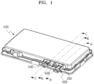
- FIG. 1 is a drawing illustrating an inverter for a solar cell module according to an embodiment
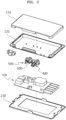
- FIG. 2 is an exploded view of the inverter illustrated in FIG. 1 .
- an inverter for a solar cell module may include a substrate 100, a case 200, a bracket 300, a first connector 400, a second connector 500, and a lens unit 600.
- an inverter may be connected to a solar cell module.
- An inverter may convert current, voltage, or power generated by a solar cell module.
- the conversion may be changing a value and/or type of current, voltage or power.
- an inverter may change a value of current, voltage, or power to another value.
- an inverter may change current, voltage, or power from direct current to alternating current or from alternating current to direct current.
- the current, voltage, or power converted by the inverter may be transmitted externally through a cable.
- a light source operating in conjunction with operation of a solar cell module may be arranged on a substrate 100.
- light irradiated from a light source may be a signal indicating an operating state of a solar cell module. That is, the operation state of a solar cell module may be output by various expression methods using light.
- a normal operation of a solar cell module may be expressed by turning the light on/off.
- a light source may remain off, and in case that there is a problem with the solar cell module, the light source may be turned on.
- a light source 110 may remain on, and in case that there is a problem with the solar cell module, the light source 110 may be turned off.
- various behavioral problems of a solar cell module may be expressed depending on time of irradiating light, a color of the light, and an intensity of the light. For example, light may be irradiated at different time intervals, different colors, and/or different intensities depending on which element among elements included in a solar cell module is experiencing a problem.
- a light source may be implemented as a liquid crystal display (LCD), a light emitting diode (LED), an organic light emitting diode (OLED), a quantum dot light emitting diode (QLED), a ⁇ LED, or the like.
- LCD liquid crystal display
- LED light emitting diode
- OLED organic light emitting diode
- QLED quantum dot light emitting diode
- a substrate 100 may be accommodated inside a case 200.
- the case 200 may include an upper case 210, a lower case 220, and a support case 230.
- the substrate 100 may be arranged between the upper case 210 and the lower case 220.
- the support case 230 may be arranged below the lower case 220.
- a bracket 300 may be coupled to the case 200 to support a first connector 400, a second connector 500, and a 600.
- the first connector 400 and the second connector 500 are arranged to electrically and physically couple an inverter and a power connector to each other or release same from each other.
- the first connector 400 and the second connector 500 may be coupled to the bracket 300 and may each be either a female connector or a male connector.
- the lens unit 600 may emit light irradiated from a light source to the outside of the case 200 so that the light may be identified by a user.
- the lens unit 600 may be coupled to the bracket 300.
- an electrical connector 700 including a bracket 300, a first connector 400, a second connector 500, and a lens unit 600 will be described.
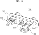
- FIG. 3 is a front perspective view of a bracket, a first connector, a second connector, and a lens unit according to an embodiment
- FIG. 4 is a rear perspective view of a bracket, a first connector, a second connector, and a lens unit according to an embodiment.
- a bracket 300, a first connector 400, a second connector 500, and a lens unit 600 may be integrally molded and implemented as one part.
- the first connector 400 and the second connector 500 are injection-molded while being aligned side by side, so that the first connector 400, the second connector 500, and the bracket 300 may be molded into one body.
- the lens unit 600 is included between the first connector 400 and the second connector 500 by injection molding, so that the bracket 300, the first connector 400, the second connector 500, and the lens unit 600 may be molded into one body.
- the bracket 300 may be manufactured from a material which does not deform after molding.
- the bracket 300 may be manufactured from a plastic resin of the bracket 300, but is not limited thereto.
- At least one of the first connector 400 or the second connector 500 may be included to protrude more than the bracket 300 in an anteroposterior direction of the bracket 300.
- the lens unit 600 may also protrude more than the bracket 300 to be exposed to the outside.
- a structure of the electrical connector 700 may be simplified. Accordingly, productivity of the electrical connector 700 may be increased, and waterproof performance of the electrical connector 700 may also be improved.
- FIG. 5 is a sectional side view taken along a virtual line A-A of FIG. 1 .
- a first connector 400 may include a first step surface ST1, a second step surface ST2, and a third step surface ST3.
- the first connector 400 may include a first tooth TW1, a first outer circumferential surface O1, and a third outer circumferential surface O3.
- first step surface ST1, the second step surface ST2, and the third step surface ST3 may each be annular.
- second step surface ST2 may be spaced apart from the first step surface ST1
- third step surface ST3 may be spaced apart from the second step surface ST2.
- first tooth TW1 may connect the first step surface ST1 and the second step surface ST2.
- first outer circumferential surface O1 is cylindrical and may connect the second step surface ST2 and the third step surface ST3.
- third outer circumferential surface O3 is cylindrical and may be connected to the third step surface ST3.
- the bracket 300 may include a first contact surface CS1, a second contact surface CS2, a third contact surface CS3, a seventh contact surface CS7, and a ninth contact surface CS9.
- the first contact surface CS1 may contact the first step surface ST1, and the first contact surface CS1 may be annular.
- the second contact surface CS2 may contact the second step surface ST2, and the second contact surface CS2 may be annular.
- the third contact surface CS3 may contact the third step surface ST3, and the third contact surface CS3 may be annular.
- the seventh contact surface CS7 may contact the first outer circumferential surface O1
- the ninth contact surface CS9 may contact the third outer circumferential surface O3.
- the seventh contact surface CS7 and the ninth contact surface CS9 may each be cylindrical.
- bracket 300 may include a third tooth TW3, and the third tooth TW3 may connect the first contact surface CS1 and the second contact surface CS2.
- first tooth TW1 and the third tooth TW3 may engage with each other in a direction increasing an area in which the bracket 300 and the first connector 400 are in contact with each other. Accordingly, coupling strength between the bracket 300 and the first connector 400 may be increased.
- first tooth TW1 and the third tooth TW3 are each illustrated as being included in a sawtooth shape, but are not limited thereto.
- the first tooth TW1 and the third tooth TW3 may be manufactured in various shapes, such as a wave shape, a rough shape, or the like to increase a surface area in contact with each other.
- an outer diameter D3 of the third outer circumferential surface O3 is shown to be smaller than an outer diameter D1 of the first outer circumferential surface O1
- a radial thickness t3 of the third step surface ST3 is shown to be smaller than a radial thickness t1 of the first step surface ST1, but this is not limited thereto.
- FIG. 6 is a sectional side view taken along a virtual line B-B of FIG 1 .
- a lens unit 600 may be manufactured from a transparent resin material.
- the lens unit 600 may include a lens 610 and an induction pipe 620 extending from the lens 610.
- the lens 610 may be positioned in front of the bracket 300 and may come into contact with an outer surface of the bracket 300.
- the induction pipe 620 may be positioned penetrating the bracket 300.
- the induction pipe 620 may include a first part 621 penetrating the bracket 300 and a second part 622 bent from the first part 621 and aligned with a light source.
- the first part 621 may be arranged spaced apart from the bracket 300.
- FIG. 7 is a sectional side view taken along a virtual line C-C of FIG. 1 .
- the second connector 500 may include a fourth step surface ST4, a fifth step surface ST5, and a sixth step surface ST6.
- the second connector 500 may include a second tooth TW2, a second outer circumferential surface O2, and a fourth outer circumferential surface O4.
- the fourth step surface ST4, the fifth step surface ST5, and the sixth step surface ST6 may each be annular.
- the fifth step surface ST5 may be spaced apart from the fourth step surface ST4, and the sixth step surface ST6 may be spaced apart from the fifth step surface ST5.
- the second tooth TW2 may connect the fourth step surface ST4 and the fifth step surface ST5.
- the second outer circumferential surface O2 is cylindrical and may connect the fifth step surface ST5 and the sixth step surface ST6.
- the fourth outer circumferential surface O4 is cylindrical and may be connected to the sixth step surface ST6.
- the bracket 300 may include a fourth contact surface CS4, a fifth contact surface CS5, a sixth contact surface CS6, an eighth contact surface CS8, and a tenth contact surface CS10.
- the fourth contact surface CS4 may contact the fourth step surface ST4, and the fourth contact surface CS4 may be annular.
- the fifth contact surface CS5 may contact the fifth step surface ST5, and the fifth contact surface CS5 may be annular.
- the sixth contact surface CS6 may contact the sixth step surface ST6, and the sixth contact surface CS6 may be annular.
- the eighth contact surface CS8 may contact the second outer circumferential surface O2.
- the tenth contact surface CS10 may contact the fourth outer circumferential surface O4, and the eighth contact surface CS8 and the tenth contact surface CS10 may each be cylindrical.
- bracket 300 may include a fourth tooth TW4, and the fourth tooth TW4 may connect the fourth contact surface CS4 and the fifth contact surface CS5.
- the second tooth TW2 and the fourth tooth TW4 may engage with each other in a direction increasing an area in which the bracket 300 and the second connector 500 are in contact with each other. Accordingly, coupling strength between the bracket 300 and the second connector 500 may be increased.
- the second tooth TW2 and the fourth tooth TW4 are each illustrated as being included in a sawtooth shape, but are not limited thereto.
- the second tooth TW2 and the fourth tooth TW4 may be manufactured in various shapes, such as a wave shape, a rough shape, or the like to increase a surface area in contact with each other.
- an outer diameter D4 of the fourth outer circumferential surface O4 is shown to be smaller than an outer diameter D2 of the second outer circumferential surface O2, and a radial thickness t6 of the sixth step surface ST6 is shown to be smaller than a radial thickness t4 of the fourth step surface ST4, but this is not limited thereto.
- FIG. 8 is a drawing illustrating an upper case according to an embodiment.
- an upper case 210 may include a rib 211 protruding from an inner side, and an upper surface of the bracket 300 may come into contact with the rib 211.
- FIG. 9 is a drawing illustrating a lower case according to an embodiment
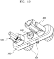
- FIG. 10 is a drawing illustrating a bracket, a first connector, a second connector, and a lens unit as viewed from below according to an embodiment.
- a lower surface of the bracket 300 may come into contact with a lower surface of a lower case 220.
- the lower case 220 may include at least one protrusion 221 protruding from an inner side.
- the bracket 300 may include at least one groove 301 arranged on the lower surface.
- the bracket 300 may come into contact with the lower case 220 when a protrusion 221 is inserted into a groove 301. Due to the presence of a groove 301 and a protrusion 221, coupling strength between the bracket 300 and the case 200 may be improved.
- an arrangement of a protrusion 221 and an arrangement of a groove 301 are not limited to those shown in FIGS. 9 and 10 .
Landscapes
- Details Of Connecting Devices For Male And Female Coupling (AREA)
- Arrangement Of Elements, Cooling, Sealing, Or The Like Of Lighting Devices (AREA)
- Inverter Devices (AREA)
- Connector Housings Or Holding Contact Members (AREA)
- Optical Couplings Of Light Guides (AREA)
Abstract
Description
- The disclosure relates to an electrical connector and an inverter connected to a solar cell module including same.
- A solar cell module may include a solar cell panel including solar cells, and a wiring box having parts, circuits, or the like connected to the solar cell panel.
- After installing a solar cell module, it may only be possible to check an operation state of the solar cell module when using a separate communication device, such as the web or an application. Because it is difficult to recognize an operation state of a solar cell module from the solar cell module itself, there is a problem that the solar cell module is not properly managed.
- To solve such a problem, a solar cell module has been proposed which is provided with structures, members, or the like capable of checking an operation state. For example, a structure has been proposed in which a light source capable of indicating an operation state is provided in a solar cell module and the operation state of the solar cell module is checked by whether the light source is driven (i.e. whether the light source blinks, intervals, or the like).
- To this end, a structure has been proposed in which a lens is positioned on a side wall of the wiring box, a light source is inserted into an induction pipe, a side of the induction pipe is fixed to a part of a wiring material and another side thereof is fixed to the lens.
- In this way, a light source, a lens, an induction pipe, and an induction pipe guide are required to check an operation state of a solar cell module. In addition, for a waterproof, an O-ring is required between the lens and a case. In this way, as the number of parts in the device for checking the operation state of the solar cell module increases, the cost also increases. In addition. as a manufacturing process of the device becomes more complex, there is a problem of lower productivity.
- An electrical connector is provided which has a function of indicating operation of a solar cell module and is included in an inverter for a solar cell module.
- In addition, an inverter for a solar cell module is provided which may increase productivity by simplifying an internal configuration.
- The problems to be solved by the disclosure are not limited to the problems mentioned above, and other problems not mentioned herein will be clearly understood by those skilled in the art from the description below.
- An electrical connector according to an aspect comprises: a first connector and a second connector arranged to electrically and physically couple an inverter and a power connector to or release same from each other; a bracket for coupling the first connector and the second connector together; and a lens unit coupled to the bracket, wherein the lens unit includes a lens exposed to the outside of a case and an induction pipe connected to the lens and a light source.
- In the electrical connector described above, the induction pipe includes a first part connected to the lens and penetrating the bracket, and a second part bent from the first part and aligned with the light source.
- An inverter for a solar cell module according to another aspect comprises: a substrate on which a light source operating in conjunction with operation of a solar cell module is arranged; a case including the substrate inside; a bracket mounted to the case; a first connector and a second connector coupled to the bracket; and a lens unit coupled to the bracket, wherein the lens unit includes a lens exposed to the outside of the case and an induction pipe connected to the lens and the light source, and the first connector includes a first step surface, a second step surface spaced apart from the first step surface, a third step surface spaced apart from the second step surface, a first tooth connecting the first step surface and the second step surface, and a first outer circumferential surface connecting the second step surface and the third step surface, and the second connector includes a fourth step surface, a fifth step surface spaced apart from the fourth step surface, a sixth step surface spaced apart from the fifth step surface, a second tooth connecting the fourth step surface and the fifth step surface, and a second outer circumferential surface connecting the fifth step surface and the sixth step surface, and the bracket includes a first contact surface contacting the first step surface, a third tooth engaging with the first tooth, a second contact surface contacting the second step surface, a third contact surface contacting the third step surface, a fourth contact surface contacting the fourth step surface, a fourth tooth engaging with the second tooth, a fifth contact surface contacting the fifth step surface, and a sixth contact surface contacting the sixth step surface, and the lens contacts an outer circumferential surface of the bracket.
- In the inverter for a solar cell module described above, the bracket includes a seventh contact surface contacting first outer circumferential surface and an eighth contact surface contacting a second outer circumferential surface.
- In the inverter for a solar cell module described above, the first connector includes a third outer circumferential surface connected to the third step surface, and the bracket includes a ninth contact surface contacting the third outer circumferential surface.
- In the inverter for a solar cell module described above, an outer diameter of the third outer circumferential surface is smaller than an outer diameter of the first outer circumferential surface.
- In the inverter for a solar cell module described above, the second connector includes a fourth outer circumferential surface connected to the sixth step surface, and the bracket includes a tenth contact surface contacting the fourth outer circumferential surface.
- In the inverter for a solar cell module described above, an outer diameter of the fourth outer circumferential surface is smaller than an outer diameter of the second outer circumferential surface.
- In the inverter for a solar cell module described above, a radial thickness of the third step surface is smaller than a radial thickness of the first step surface, and a radial thickness of the sixth step surface is smaller than a radial thickness of the fourth step surface.
- In the inverter for a solar cell module described above, the lens protrudes more than the bracket and is exposed to the outside.
- In the inverter for a solar cell module described above, the case includes an upper case and a lower case coupled with the upper case, and the upper case includes a rib protruding from an inner side, and an upper surface of the bracket contacts the rib, and a lower surface of the bracket contacts a lower surface of the lower case.
- In the inverter for a solar cell module described above, the induction pipe includes a first part connected to the lens and penetrating the bracket and a second part bent from the first part and aligned with the light source.
- According to an embodiment, a lens unit and a bracket including a connector and an induction pipe may be manufactured by integral injection molding, thereby simplifying a configuration and increasing productivity.
- According to an embodiment, a lens unit and a bracket including a connector and an induction pipe may be manufactured by integral injection molding, thereby facilitating assembly.
- According to an embodiment, a lens unit and a bracket including a connector and an induction pipe may be manufactured by integral injection molding, thereby improving waterproof performance.
-
-
FIG. 1 is a diagram illustrating an inverter for a solar cell module according to an embodiment. -
FIG. 2 is an exploded view of the inverter shown inFIG. 1 . -
FIG. 3 is a front perspective view of a bracket, a first connector, a second connector, and a lens unit according to an embodiment. -
FIG. 4 is a rear perspective view of a bracket, a first connector, a second connector, and a lens unit according to an embodiment. -
FIG. 5 is a sectional side view taken along a virtual line A-AFIG. 1 . -
FIG. 6 is a sectional side view taken along a virtual line B-B ofFIG. 1 . -
FIG. 7 is a sectional side view taken along a virtual line C-C ofFIG. 1 . -
FIG. 8 is a drawing illustrating an upper case according to an embodiment. -
FIG. 9 is a diagram illustrating a lower case according to an embodiment. -
FIG. 10 is a drawing illustrating a bracket, a first connector, a second connector, and a lens unit as viewed from below according to an embodiment. - An electrical connector according to an aspect includes: a first connector and a second connector arranged to electrically and physically couple an inverter and a power connector to each other or release same from each other; a bracket for coupling the first connector and the second connector together; and a lens unit coupled to the bracket, wherein the lens unit includes a lens exposed to the outside of a case and an induction pipe connected to the lens and a light source.
- Hereinafter, preferred embodiments of the disclosure will be described in detail with reference to the attached drawings.
- However, the technical idea of the disclosure is not limited to some of the embodiments described, but may be implemented in various different forms, and in the scope of the technical idea of the disclosure, one or more of the components among the embodiments may be selectively combined or substituted for use.
- In addition, terms (including technical and scientific terms) used in the embodiments of the disclosure may be interpreted as having a meaning which may be generally understood by a person of ordinary skill in the technical field to which the disclosure belongs, unless explicitly and specifically defined and described, and terms that are commonly used, such as terms defined in a dictionary, may be interpreted in consideration of the contextual meaning of the related art.
- In addition, the terms used in the embodiments of the disclosure may be for the purpose of describing the embodiments and are not intended to limit the disclosure.
- In this specification, the singular may also include the plural unless specifically stated otherwise in a phrase, and in case that it is described as 'at least one (or one or more) of A, B, or C', it may include one or more of all combinations which may be combined with A, B, and C.
- In addition, in describing components of the embodiments of the disclosure, terms, such as first, second, A, B, (a), (b), or the like may be used.
- Such a term is only intended to distinguish a component from another, and is not intended to limit the nature, order, sequence, or the like of the component.
- In addition, in case that a component is described as being 'connected', 'coupled' or 'linked' to another component, it may include not only cases where the component is directly connected, coupled or linked to the other component, but also cases where the component is 'connected', 'coupled' or 'linked' by another component between the component and another component.
- In addition, in case that it is described as being included or arranged 'upper (above) or lower (below)' each component, 'upper (above) or lower (below)' may include not only cases where two components are in direct contact with each other, but also cases where one or more other components are included or arranged between the two components. In addition, in case that it is expressed as 'upper (above) or lower (below)', it may include the meaning of not only an upward direction but also a downward direction based on one component.
-
FIG. 1 is a drawing illustrating an inverter for a solar cell module according to an embodiment, andFIG. 2 is an exploded view of the inverter illustrated inFIG. 1 . - Referring to
FIGS. 1 and2 , an inverter for a solar cell module (hereinafter referred to as an 'inverter') may include asubstrate 100, acase 200, abracket 300, afirst connector 400, asecond connector 500, and alens unit 600. For example, an inverter may be connected to a solar cell module. - An inverter may convert current, voltage, or power generated by a solar cell module. In this regard, the conversion may be changing a value and/or type of current, voltage or power. For example, an inverter may change a value of current, voltage, or power to another value. In addition, an inverter may change current, voltage, or power from direct current to alternating current or from alternating current to direct current. The current, voltage, or power converted by the inverter may be transmitted externally through a cable.
- A light source operating in conjunction with operation of a solar cell module may be arranged on a
substrate 100. For example, light irradiated from a light source may be a signal indicating an operating state of a solar cell module. That is, the operation state of a solar cell module may be output by various expression methods using light. - As an example, a normal operation of a solar cell module may be expressed by turning the light on/off. For example, in case that a solar cell module is operating normally, a light source may remain off, and in case that there is a problem with the solar cell module, the light source may be turned on. In addition, in case that a solar cell module is operating normally, a light source 110 may remain on, and in case that there is a problem with the solar cell module, the light source 110 may be turned off.
- As another example, various behavioral problems of a solar cell module may be expressed depending on time of irradiating light, a color of the light, and an intensity of the light. For example, light may be irradiated at different time intervals, different colors, and/or different intensities depending on which element among elements included in a solar cell module is experiencing a problem.
- Any device which may be irradiated with light may be considered as a light source without limitation. For example, a light source may be implemented as a liquid crystal display (LCD), a light emitting diode (LED), an organic light emitting diode (OLED), a quantum dot light emitting diode (QLED), a µLED, or the like.
- A
substrate 100 may be accommodated inside acase 200. For example, thecase 200 may include anupper case 210, alower case 220, and asupport case 230. Thesubstrate 100 may be arranged between theupper case 210 and thelower case 220. Thesupport case 230 may be arranged below thelower case 220. - A
bracket 300 may be coupled to thecase 200 to support afirst connector 400, asecond connector 500, and a 600. - The
first connector 400 and thesecond connector 500 are arranged to electrically and physically couple an inverter and a power connector to each other or release same from each other. For example, thefirst connector 400 and thesecond connector 500 may be coupled to thebracket 300 and may each be either a female connector or a male connector. - The
lens unit 600 may emit light irradiated from a light source to the outside of thecase 200 so that the light may be identified by a user. For example, thelens unit 600 may be coupled to thebracket 300. - Hereinafter, with reference to
FIGS. 3 to 10 , anelectrical connector 700 including abracket 300, afirst connector 400, asecond connector 500, and alens unit 600 will be described. -
FIG. 3 is a front perspective view of a bracket, a first connector, a second connector, and a lens unit according to an embodiment, andFIG. 4 is a rear perspective view of a bracket, a first connector, a second connector, and a lens unit according to an embodiment. - Referring to
FIGS. 3 and4 , abracket 300, afirst connector 400, asecond connector 500, and alens unit 600 may be integrally molded and implemented as one part. - First, the
first connector 400 and thesecond connector 500 are injection-molded while being aligned side by side, so that thefirst connector 400, thesecond connector 500, and thebracket 300 may be molded into one body. Thereafter, thelens unit 600 is included between thefirst connector 400 and thesecond connector 500 by injection molding, so that thebracket 300, thefirst connector 400, thesecond connector 500, and thelens unit 600 may be molded into one body. - The
bracket 300 may be manufactured from a material which does not deform after molding. For example, thebracket 300 may be manufactured from a plastic resin of thebracket 300, but is not limited thereto. - At least one of the
first connector 400 or thesecond connector 500 may be included to protrude more than thebracket 300 in an anteroposterior direction of thebracket 300. Thelens unit 600 may also protrude more than thebracket 300 to be exposed to the outside. - In this way, by implementing four parts into one body, a structure of the
electrical connector 700 may be simplified. Accordingly, productivity of theelectrical connector 700 may be increased, and waterproof performance of theelectrical connector 700 may also be improved. -
FIG. 5 is a sectional side view taken along a virtual line A-A ofFIG. 1 . - Referring to
FIG. 5 , afirst connector 400 may include a first step surface ST1, a second step surface ST2, and a third step surface ST3. In addition, thefirst connector 400 may include a first tooth TW1, a first outer circumferential surface O1, and a third outer circumferential surface O3. - For example, the first step surface ST1, the second step surface ST2, and the third step surface ST3 may each be annular. In addition, the second step surface ST2 may be spaced apart from the first step surface ST1, and the third step surface ST3 may be spaced apart from the second step surface ST2.
- For example, the first tooth TW1 may connect the first step surface ST1 and the second step surface ST2. In addition, the first outer circumferential surface O1 is cylindrical and may connect the second step surface ST2 and the third step surface ST3. In addition, the third outer circumferential surface O3 is cylindrical and may be connected to the third step surface ST3.
- The
bracket 300 may include a first contact surface CS1, a second contact surface CS2, a third contact surface CS3, a seventh contact surface CS7, and a ninth contact surface CS9. - For example, the first contact surface CS1 may contact the first step surface ST1, and the first contact surface CS1 may be annular. In addition, the second contact surface CS2 may contact the second step surface ST2, and the second contact surface CS2 may be annular. In addition, the third contact surface CS3 may contact the third step surface ST3, and the third contact surface CS3 may be annular. In addition, the seventh contact surface CS7 may contact the first outer circumferential surface O1, and the ninth contact surface CS9 may contact the third outer circumferential surface O3. The seventh contact surface CS7 and the ninth contact surface CS9 may each be cylindrical.
- In addition, the
bracket 300 may include a third tooth TW3, and the third tooth TW3 may connect the first contact surface CS1 and the second contact surface CS2. - For example, the first tooth TW1 and the third tooth TW3 may engage with each other in a direction increasing an area in which the
bracket 300 and thefirst connector 400 are in contact with each other. Accordingly, coupling strength between thebracket 300 and thefirst connector 400 may be increased. InFIG. 5 , the first tooth TW1 and the third tooth TW3 are each illustrated as being included in a sawtooth shape, but are not limited thereto. The first tooth TW1 and the third tooth TW3 may be manufactured in various shapes, such as a wave shape, a rough shape, or the like to increase a surface area in contact with each other. - In
FIG. 5 , an outer diameter D3 of the third outer circumferential surface O3 is shown to be smaller than an outer diameter D1 of the first outer circumferential surface O1, and a radial thickness t3 of the third step surface ST3 is shown to be smaller than a radial thickness t1 of the first step surface ST1, but this is not limited thereto. -
FIG. 6 is a sectional side view taken along a virtual line B-B ofFIG 1 . - Referring to
FIG. 6 , alens unit 600 may be manufactured from a transparent resin material. In addition, thelens unit 600 may include alens 610 and aninduction pipe 620 extending from thelens 610. - For example, the
lens 610 may be positioned in front of thebracket 300 and may come into contact with an outer surface of thebracket 300. Theinduction pipe 620 may be positioned penetrating thebracket 300. For example, theinduction pipe 620 may include afirst part 621 penetrating thebracket 300 and asecond part 622 bent from thefirst part 621 and aligned with a light source. In this regard, thefirst part 621 may be arranged spaced apart from thebracket 300. -
FIG. 7 is a sectional side view taken along a virtual line C-C ofFIG. 1 . - Referring to
FIG. 7 , thesecond connector 500 may include a fourth step surface ST4, a fifth step surface ST5, and a sixth step surface ST6. In addition, thesecond connector 500 may include a second tooth TW2, a second outer circumferential surface O2, and a fourth outer circumferential surface O4. - For example, the fourth step surface ST4, the fifth step surface ST5, and the sixth step surface ST6 may each be annular. In addition, the fifth step surface ST5 may be spaced apart from the fourth step surface ST4, and the sixth step surface ST6 may be spaced apart from the fifth step surface ST5.
- For example, the second tooth TW2 may connect the fourth step surface ST4 and the fifth step surface ST5. In addition, the second outer circumferential surface O2 is cylindrical and may connect the fifth step surface ST5 and the sixth step surface ST6. In addition, the fourth outer circumferential surface O4 is cylindrical and may be connected to the sixth step surface ST6.
- The
bracket 300 may include a fourth contact surface CS4, a fifth contact surface CS5, a sixth contact surface CS6, an eighth contact surface CS8, and a tenth contact surface CS10. - For example, the fourth contact surface CS4 may contact the fourth step surface ST4, and the fourth contact surface CS4 may be annular. In addition, the fifth contact surface CS5 may contact the fifth step surface ST5, and the fifth contact surface CS5 may be annular. In addition, the sixth contact surface CS6 may contact the sixth step surface ST6, and the sixth contact surface CS6 may be annular. In addition, the eighth contact surface CS8 may contact the second outer circumferential surface O2. In addition, the tenth contact surface CS10 may contact the fourth outer circumferential surface O4, and the eighth contact surface CS8 and the tenth contact surface CS10 may each be cylindrical.
- In addition, the
bracket 300 may include a fourth tooth TW4, and the fourth tooth TW4 may connect the fourth contact surface CS4 and the fifth contact surface CS5. - For example, the second tooth TW2 and the fourth tooth TW4 may engage with each other in a direction increasing an area in which the
bracket 300 and thesecond connector 500 are in contact with each other. Accordingly, coupling strength between thebracket 300 and thesecond connector 500 may be increased. InFIG. 7 , the second tooth TW2 and the fourth tooth TW4 are each illustrated as being included in a sawtooth shape, but are not limited thereto. The second tooth TW2 and the fourth tooth TW4 may be manufactured in various shapes, such as a wave shape, a rough shape, or the like to increase a surface area in contact with each other. - In
FIG. 7 , an outer diameter D4 of the fourth outer circumferential surface O4 is shown to be smaller than an outer diameter D2 of the second outer circumferential surface O2, and a radial thickness t6 of the sixth step surface ST6 is shown to be smaller than a radial thickness t4 of the fourth step surface ST4, but this is not limited thereto. -
FIG. 8 is a drawing illustrating an upper case according to an embodiment. - Referring to
FIG. 8 , anupper case 210 may include arib 211 protruding from an inner side, and an upper surface of thebracket 300 may come into contact with therib 211. -
FIG. 9 is a drawing illustrating a lower case according to an embodiment, andFIG. 10 is a drawing illustrating a bracket, a first connector, a second connector, and a lens unit as viewed from below according to an embodiment. - Referring to
FIGS. 9 and10 . a lower surface of thebracket 300 may come into contact with a lower surface of alower case 220. At this time, thelower case 220 may include at least oneprotrusion 221 protruding from an inner side. In addition, thebracket 300 may include at least onegroove 301 arranged on the lower surface. For example, thebracket 300 may come into contact with thelower case 220 when aprotrusion 221 is inserted into agroove 301. Due to the presence of agroove 301 and aprotrusion 221, coupling strength between thebracket 300 and thecase 200 may be improved. - However, an arrangement of a
protrusion 221 and an arrangement of agroove 301 are not limited to those shown inFIGS. 9 and10 . In other words, there is no limitation on the number and arrangement of aprotrusion 221 and agroove 301 when aprotrusion 221 may be inserted into agroove 301. - It should be understood that the above-described embodiments of the disclosure are illustrative in all respects and not restrictive, and the scope of the disclosure is indicated by the claims described below than by the detailed description described above. In addition, the meaning and scope of the claims, as well as all changes or modifications derived from the equivalent concept, should be interpreted as being included in the scope of the disclosure.
Claims (12)
- An electrical connector, comprising:a first connector and a second connector arranged to electrically and physically couple an inverter and a power connector to each other or release same from each other;a bracket for coupling the first connector and the second connector together; anda lens unit coupled to the bracket, whereinthe lens unit includes a lens exposed to an outside of a case and an induction pipe connected to the lens and a light source.
- The electrical connector of claim 1, whereinthe induction pipe includesa first part connected to the lens and penetrating the bracket and a second part bent from the first part and aligned with the light source.
- An inverter for a solar cell module, comprising:a substrate on which a light source operating in conjunction with operation of a solar cell module is arranged;a case including the substrate inside;a bracket mounted on the case;a first connector and a second connector coupled to the bracket; anda lens unit coupled to the bracket, whereinthe lens unit includes a lens exposed to an outside of the case and an induction pipe connected to the lens and the light source, andthe first connector includes a first step surface, a second step surface spaced apart from the first step surface, a third step surface spaced apart from the second step surface, a first tooth connecting the first step surface and the second step surface, and a first outer circumferential surface connecting the second step surface and the third step surface, andthe second connector includes a fourth step surface, a fifth step surface spaced apart from the fourth step surface, a sixth step surface spaced apart from the fifth step surface, a second tooth connecting the fourth step surface and the fifth step surface, and a second outer circumferential surface connecting the fifth step surface and the sixth step surface, andthe bracket includes a first contact surface contacting the first step surface, a third tooth engaging with the first tooth, a second contact surface contacting the second step surface, a third contact surface contacting the third step surface, a fourth contact surface contacting the fourth step surface, a fourth tooth engaging with the second tooth, a fifth contact surface contacting the fifth step surface, and a sixth contact surface contacting the sixth step surface, andthe lens contacts an outer surface of the bracket.
- The inverter for a solar cell module of claim 3, wherein
the bracket includes a seventh contact surface contacting first outer circumferential surface and an eighth contact surface contacting the second outer circumferential surface. - The inverter for a solar cell module of claim 4, whereinthe first connector includes a third outer circumferential surface connected to the third step surface, andthe bracket includes a ninth contact surface contacting the third outer circumferential surface.
- The inverter for a solar cell module of claim 5, wherein
an outer diameter of the third outer circumferential surface is smaller than an outer diameter of the first outer circumferential surface. - The inverter for a solar cell module of claim 6, whereinthe second connector includes a fourth outer circumferential surface connected to the sixth step surface, andthe bracket includes a tenth contact surface contacting the fourth outer circumferential surface.
- The inverter for a solar cell module of claim 7, wherein
an outer diameter of the fourth outer circumferential surface is smaller than an outer diameter of the second outer circumferential surface. - The inverter for a solar cell module of claim 8, wherein
a radial thickness of the third step surface is smaller than a radial thickness of the first step surface, and a radial thickness of the sixth step surface is smaller than a radial thickness of the fourth step surface. - The inverter for a solar cell module of claim 9, wherein
the lens protrudes more than the bracket and is exposed to the outside. - The inverter for a solar cell module of claim 10, whereinthe case includes an upper case and a lower case coupled to the upper case, andthe upper case includes a rib protruding from an inner side, andan upper surface of the bracket contacts the rib, and a lower surface of the bracket contacts a lower surface of the lower case.
- The inverter for a solar cell module of claim 11, wherein
the induction pipe includes a first part connected to the lens and penetrating the bracket and a second part bent from the first part and aligned with the light source.
Applications Claiming Priority (2)
| Application Number | Priority Date | Filing Date | Title |
|---|---|---|---|
| KR1020230011701A KR102775222B1 (en) | 2023-01-30 | 2023-01-30 | Electric connector and inverter for solar cell module including the same |
| PCT/KR2024/001294 WO2024162707A1 (en) | 2023-01-30 | 2024-01-26 | Electrical connector and inverter for solar cell module including same |
Publications (2)
| Publication Number | Publication Date |
|---|---|
| EP4557534A1 true EP4557534A1 (en) | 2025-05-21 |
| EP4557534A4 EP4557534A4 (en) | 2025-11-19 |
Family
ID=92147237
Family Applications (1)
| Application Number | Title | Priority Date | Filing Date |
|---|---|---|---|
| EP24750508.4A Pending EP4557534A4 (en) | 2023-01-30 | 2024-01-26 | ELECTRICAL CONNECTOR AND INVERTER FOR A SOLAR CELL MODULE SO THAT |
Country Status (6)
| Country | Link |
|---|---|
| US (1) | US20260005646A1 (en) |
| EP (1) | EP4557534A4 (en) |
| JP (1) | JP7856856B2 (en) |
| KR (1) | KR102775222B1 (en) |
| CN (1) | CN120188353A (en) |
| WO (1) | WO2024162707A1 (en) |
Family Cites Families (17)
| Publication number | Priority date | Publication date | Assignee | Title |
|---|---|---|---|---|
| US5062807A (en) * | 1990-10-22 | 1991-11-05 | Woodhead Industries, Inc. | Lighted electrical connector permitting multi directional viewing |
| US5885100A (en) * | 1997-05-12 | 1999-03-23 | Molex Incorporated | Electrical connector with light transmission means |
| US6318909B1 (en) * | 1999-02-11 | 2001-11-20 | Agilent Technologies, Inc. | Integrated packaging system for optical communications devices that provides automatic alignment with optical fibers |
| US7086892B2 (en) * | 2003-02-28 | 2006-08-08 | Leviton Manufacturing Co., Inc. | Live circuit indicator for plugs and receptacles |
| US20080289681A1 (en) | 2007-02-27 | 2008-11-27 | Adriani Paul M | Structures for low cost, reliable solar modules |
| US7914298B2 (en) * | 2008-10-10 | 2011-03-29 | Tyco Electronics Corporation | Solar box and two position solar connectors |
| BR112012030690A2 (en) | 2010-06-01 | 2016-09-13 | Apple Inc | hybrid optical connector |
| TWM423402U (en) * | 2011-10-18 | 2012-02-21 | Ji-Ren Yang | Bus box |
| US8962998B2 (en) * | 2012-02-08 | 2015-02-24 | Shoals Technologies Group, Llc | Solar panel junction box capable of integrating with a variety of accessory modules, and method of use |
| KR101477685B1 (en) | 2013-05-31 | 2014-12-30 | (주) 이이시스 | Casing device for micro inverter |
| EP3593186A1 (en) | 2017-03-07 | 2020-01-15 | Corning Optical Communications LLC | Universal photonic adaptor for coupling an optical connector to an optoelectronic substrate |
| EP3809590B1 (en) * | 2017-03-29 | 2023-09-20 | Solaredge Technologies Ltd. | Heat dissipation for a photovoltaic junction box |
| KR101880477B1 (en) * | 2017-09-26 | 2018-07-20 | 엘지전자 주식회사 | Solar cell module and error detector for solar cell module |
| KR102615861B1 (en) * | 2018-07-25 | 2023-12-21 | 상라오 징코 솔라 테크놀러지 디벨롭먼트 컴퍼니, 리미티드 | Solar cell module |
| US10490916B1 (en) * | 2018-11-13 | 2019-11-26 | Dinkle Enterprise Co., Ltd. | Light-emitting terminal block structure |
| WO2021120669A1 (en) * | 2019-12-20 | 2021-06-24 | 青岛海信宽带多媒体技术有限公司 | Optical module |
| KR102845691B1 (en) * | 2020-12-10 | 2025-08-13 | 현대자동차주식회사 | Inverter integrated to motor |
-
2023
- 2023-01-30 KR KR1020230011701A patent/KR102775222B1/en active Active
-
2024
- 2024-01-26 WO PCT/KR2024/001294 patent/WO2024162707A1/en not_active Ceased
- 2024-01-26 EP EP24750508.4A patent/EP4557534A4/en active Pending
- 2024-01-26 US US19/107,358 patent/US20260005646A1/en active Pending
- 2024-01-26 CN CN202480004735.3A patent/CN120188353A/en active Pending
- 2024-01-26 JP JP2025522787A patent/JP7856856B2/en active Active
Also Published As
| Publication number | Publication date |
|---|---|
| KR102775222B1 (en) | 2025-03-04 |
| CN120188353A (en) | 2025-06-20 |
| JP7856856B2 (en) | 2026-05-11 |
| WO2024162707A1 (en) | 2024-08-08 |
| KR20240119526A (en) | 2024-08-06 |
| EP4557534A4 (en) | 2025-11-19 |
| US20260005646A1 (en) | 2026-01-01 |
| JP2025537090A (en) | 2025-11-14 |
Similar Documents
| Publication | Publication Date | Title |
|---|---|---|
| JP4481935B2 (en) | High power LED housing and manufacturing method thereof | |
| US20060002125A1 (en) | Light emitting diode module for automobile headlights and automobile headlight having the same | |
| CN102650408A (en) | Lighting structure of charging connector | |
| US20110111612A1 (en) | Electrical connector assembly with sealing washer | |
| JP2010505254A5 (en) | ||
| JP2003520991A (en) | Optical transceiver module with internal optical waveguide | |
| JP5534430B2 (en) | Surface emitting module and surface emitting lighting device | |
| EP4661221A1 (en) | Electrical connector and solar cell module inverter comprising same | |
| US11898708B1 (en) | Lighting device having integrated end cap | |
| US20260005646A1 (en) | Electrical connector and inverter for solar cell module including same | |
| KR102615861B1 (en) | Solar cell module | |
| CN103298295A (en) | Flexible dust cover for use with a parallel optical communications module to prevent airborne matter from entering the module, and a method | |
| JP2008270264A (en) | Photointerrupter | |
| JP5928315B2 (en) | Hybrid connector | |
| CN114641647A (en) | Bendable PCB with heat dissipation function | |
| CN114901994B (en) | LED lighting | |
| CN212961376U (en) | Work lamp with graphic warning function | |
| KR102476513B1 (en) | Led group type lighting device of synthetic resin transmission type | |
| KR20190129441A (en) | A surface-emitting laser packgae and optical module including the same | |
| CN221407704U (en) | Charging device | |
| US20150156901A1 (en) | Inverter for electric vehicle | |
| JP5376672B2 (en) | Surface emitting module and surface emitting lighting device | |
| JP7736927B2 (en) | Solar cell device and covering member applied thereto | |
| TW200827870A (en) | Backlight module | |
| EP3707750A1 (en) | Optoelectronic modules having locking assemblies and methods for manufacturing the same |
Legal Events
| Date | Code | Title | Description |
|---|---|---|---|
| STAA | Information on the status of an ep patent application or granted ep patent |
Free format text: STATUS: THE INTERNATIONAL PUBLICATION HAS BEEN MADE |
|
| PUAI | Public reference made under article 153(3) epc to a published international application that has entered the european phase |
Free format text: ORIGINAL CODE: 0009012 |
|
| STAA | Information on the status of an ep patent application or granted ep patent |
Free format text: STATUS: REQUEST FOR EXAMINATION WAS MADE |
|
| 17P | Request for examination filed |
Effective date: 20250213 |
|
| AK | Designated contracting states |
Kind code of ref document: A1 Designated state(s): AL AT BE BG CH CY CZ DE DK EE ES FI FR GB GR HR HU IE IS IT LI LT LU LV MC ME MK MT NL NO PL PT RO RS SE SI SK SM TR |
|
| REG | Reference to a national code |
Ref country code: DE Ref legal event code: R079 Free format text: PREVIOUS MAIN CLASS: H01R0013629000 Ipc: H02S0040340000 |
|
| STAA | Information on the status of an ep patent application or granted ep patent |
Free format text: STATUS: EXAMINATION IS IN PROGRESS |
|
| A4 | Supplementary search report drawn up and despatched |
Effective date: 20251016 |
|
| RIC1 | Information provided on ipc code assigned before grant |
Ipc: H02S 40/34 20140101AFI20251010BHEP Ipc: H02J 3/38 20060101ALI20251010BHEP Ipc: H01R 13/717 20060101ALI20251010BHEP Ipc: H05K 5/00 20250101ALI20251010BHEP Ipc: G02B 6/38 20060101ALI20251010BHEP Ipc: G02B 6/24 20060101ALI20251010BHEP Ipc: H02S 40/32 20140101ALI20251010BHEP Ipc: H01R 12/72 20110101ALN20251010BHEP |
|
| 17Q | First examination report despatched |
Effective date: 20251028 |
|
| DAV | Request for validation of the european patent (deleted) | ||
| DAX | Request for extension of the european patent (deleted) |