EP4557507A1 - Antenna device and wireless mobile terminal - Google Patents
Antenna device and wireless mobile terminal Download PDFInfo
- Publication number
- EP4557507A1 EP4557507A1 EP24209027.2A EP24209027A EP4557507A1 EP 4557507 A1 EP4557507 A1 EP 4557507A1 EP 24209027 A EP24209027 A EP 24209027A EP 4557507 A1 EP4557507 A1 EP 4557507A1
- Authority
- EP
- European Patent Office
- Prior art keywords
- support
- antenna
- bottom plate
- integrated circuit
- border
- Prior art date
- Legal status (The legal status is an assumption and is not a legal conclusion. Google has not performed a legal analysis and makes no representation as to the accuracy of the status listed.)
- Pending
Links
Images




Classifications
-
- H—ELECTRICITY
- H01—ELECTRIC ELEMENTS
- H01Q—ANTENNAS, i.e. RADIO AERIALS
- H01Q21/00—Antenna arrays or systems
- H01Q21/06—Arrays of individually energised antenna units similarly polarised and spaced apart
-
- H—ELECTRICITY
- H01—ELECTRIC ELEMENTS
- H01Q—ANTENNAS, i.e. RADIO AERIALS
- H01Q21/00—Antenna arrays or systems
- H01Q21/28—Combinations of substantially independent non-interacting antenna units or systems
-
- H—ELECTRICITY
- H01—ELECTRIC ELEMENTS
- H01Q—ANTENNAS, i.e. RADIO AERIALS
- H01Q1/00—Details of, or arrangements associated with, antennas
- H01Q1/12—Supports; Mounting means
-
- H—ELECTRICITY
- H01—ELECTRIC ELEMENTS
- H01Q—ANTENNAS, i.e. RADIO AERIALS
- H01Q1/00—Details of, or arrangements associated with, antennas
- H01Q1/12—Supports; Mounting means
- H01Q1/1207—Supports; Mounting means for fastening a rigid aerial element
-
- H—ELECTRICITY
- H01—ELECTRIC ELEMENTS
- H01Q—ANTENNAS, i.e. RADIO AERIALS
- H01Q1/00—Details of, or arrangements associated with, antennas
- H01Q1/12—Supports; Mounting means
- H01Q1/22—Supports; Mounting means by structural association with other equipment or articles
- H01Q1/24—Supports; Mounting means by structural association with other equipment or articles with receiving set
- H01Q1/241—Supports; Mounting means by structural association with other equipment or articles with receiving set used in mobile communications, e.g. GSM
- H01Q1/242—Supports; Mounting means by structural association with other equipment or articles with receiving set used in mobile communications, e.g. GSM specially adapted for hand-held use
-
- H—ELECTRICITY
- H01—ELECTRIC ELEMENTS
- H01Q—ANTENNAS, i.e. RADIO AERIALS
- H01Q1/00—Details of, or arrangements associated with, antennas
- H01Q1/12—Supports; Mounting means
- H01Q1/22—Supports; Mounting means by structural association with other equipment or articles
- H01Q1/24—Supports; Mounting means by structural association with other equipment or articles with receiving set
- H01Q1/241—Supports; Mounting means by structural association with other equipment or articles with receiving set used in mobile communications, e.g. GSM
- H01Q1/242—Supports; Mounting means by structural association with other equipment or articles with receiving set used in mobile communications, e.g. GSM specially adapted for hand-held use
- H01Q1/243—Supports; Mounting means by structural association with other equipment or articles with receiving set used in mobile communications, e.g. GSM specially adapted for hand-held use with built-in antennas
-
- H—ELECTRICITY
- H01—ELECTRIC ELEMENTS
- H01Q—ANTENNAS, i.e. RADIO AERIALS
- H01Q1/00—Details of, or arrangements associated with, antennas
- H01Q1/36—Structural form of radiating elements, e.g. cone, spiral, umbrella; Particular materials used therewith
- H01Q1/38—Structural form of radiating elements, e.g. cone, spiral, umbrella; Particular materials used therewith formed by a conductive layer on an insulating support
-
- H—ELECTRICITY
- H01—ELECTRIC ELEMENTS
- H01Q—ANTENNAS, i.e. RADIO AERIALS
- H01Q1/00—Details of, or arrangements associated with, antennas
- H01Q1/48—Earthing means; Earth screens; Counterpoises
-
- H—ELECTRICITY
- H01—ELECTRIC ELEMENTS
- H01Q—ANTENNAS, i.e. RADIO AERIALS
- H01Q1/00—Details of, or arrangements associated with, antennas
- H01Q1/52—Means for reducing coupling between antennas; Means for reducing coupling between an antenna and another structure
- H01Q1/521—Means for reducing coupling between antennas; Means for reducing coupling between an antenna and another structure reducing the coupling between adjacent antennas
- H01Q1/523—Means for reducing coupling between antennas; Means for reducing coupling between an antenna and another structure reducing the coupling between adjacent antennas between antennas of an array
-
- H—ELECTRICITY
- H01—ELECTRIC ELEMENTS
- H01Q—ANTENNAS, i.e. RADIO AERIALS
- H01Q1/00—Details of, or arrangements associated with, antennas
- H01Q1/52—Means for reducing coupling between antennas; Means for reducing coupling between an antenna and another structure
- H01Q1/526—Electromagnetic shields
-
- H—ELECTRICITY
- H01—ELECTRIC ELEMENTS
- H01Q—ANTENNAS, i.e. RADIO AERIALS
- H01Q21/00—Antenna arrays or systems
-
- H—ELECTRICITY
- H01—ELECTRIC ELEMENTS
- H01Q—ANTENNAS, i.e. RADIO AERIALS
- H01Q21/00—Antenna arrays or systems
- H01Q21/06—Arrays of individually energised antenna units similarly polarised and spaced apart
- H01Q21/061—Two dimensional planar arrays
- H01Q21/065—Patch antenna array
-
- H—ELECTRICITY
- H01—ELECTRIC ELEMENTS
- H01Q—ANTENNAS, i.e. RADIO AERIALS
- H01Q5/00—Arrangements for simultaneous operation of antennas on two or more different wavebands, e.g. dual-band or multi-band arrangements
- H01Q5/30—Arrangements for providing operation on different wavebands
- H01Q5/307—Individual or coupled radiating elements, each element being fed in an unspecified way
- H01Q5/314—Individual or coupled radiating elements, each element being fed in an unspecified way using frequency dependent circuits or components, e.g. trap circuits or capacitors
- H01Q5/335—Individual or coupled radiating elements, each element being fed in an unspecified way using frequency dependent circuits or components, e.g. trap circuits or capacitors at the feed, e.g. for impedance matching
-
- H—ELECTRICITY
- H01—ELECTRIC ELEMENTS
- H01Q—ANTENNAS, i.e. RADIO AERIALS
- H01Q5/00—Arrangements for simultaneous operation of antennas on two or more different wavebands, e.g. dual-band or multi-band arrangements
- H01Q5/40—Imbricated or interleaved structures; Combined or electromagnetically coupled arrangements, e.g. comprising two or more non-connected fed radiating elements
-
- H—ELECTRICITY
- H01—ELECTRIC ELEMENTS
- H01Q—ANTENNAS, i.e. RADIO AERIALS
- H01Q9/00—Electrically-short antennas having dimensions not more than twice the operating wavelength and consisting of conductive active radiating elements
- H01Q9/04—Resonant antennas
- H01Q9/0407—Substantially flat resonant element parallel to ground plane, e.g. patch antenna
- H01Q9/0421—Substantially flat resonant element parallel to ground plane, e.g. patch antenna with a shorting wall or a shorting pin at one end of the element
-
- H—ELECTRICITY
- H01—ELECTRIC ELEMENTS
- H01Q—ANTENNAS, i.e. RADIO AERIALS
- H01Q9/00—Electrically-short antennas having dimensions not more than twice the operating wavelength and consisting of conductive active radiating elements
- H01Q9/04—Resonant antennas
- H01Q9/0407—Substantially flat resonant element parallel to ground plane, e.g. patch antenna
- H01Q9/045—Substantially flat resonant element parallel to ground plane, e.g. patch antenna with particular feeding means
Definitions
- the present application relates to the technical field of electronic device, and in particular to an antenna device and a wireless mobile terminal.
- wireless communication devices such as a mobile phone and a smart watch
- the functions of wireless communication devices are constantly evolving, and the requirements of the device appearance and the wireless communication performance by the market are also constantly increasing. How to improve the communication performance of the wireless mobile terminals has become an urgent technical problem to be solved.
- Embodiments of the present application provide an antenna device and a wireless mobile terminal, which can improve the wireless communication performance of the wireless mobile terminal.
- an antenna device including: a frame, including a border and a hollow space surrounded and formed by the border; a support, connected to the border and extending towards the hollow space; and an antenna assembly, including a first antenna module and a second antenna module.
- the first antenna module is arranged on the support and includes a plurality of first antenna units spaced apart from one another, and the second antenna module includes a plurality of second antenna units.
- the first antenna module and the support are insulated from each other, and the support includes a conductive material and is reused as at least a portion of the second antenna units.
- embodiments of the present application provide a wireless mobile terminal including the antenna device according to any one of the above embodiments in the first aspect.
- the antenna device includes the frame, the support and the antenna assembly.
- the frame can surround to form the hollow space for the antenna assembly and the support.
- the support is connected to the border and located in the hollow space to provide an arranging position for the antenna assembly.
- the antenna assembly includes the first antenna module and the second antenna module, which can improve the antenna function.
- the first antenna module includes the plurality of first antenna units arranged on the support, which can support the first antenna units.
- the support includes the conductive material and can be reused as at least a portion of the second antenna units, so as to further improve the function of the support and reduce a space occupied by the entire second antenna module.
- Fig. 1 is a structural schematic view of an antenna device according to an embodiment of the present application
- Fig. 2 is a locally enlarged structural schematic view of an antenna device according to an embodiment of the present application
- Fig. 3 is a structural schematic view of a support of an antenna device according to an embodiment of the present application
- Fig. 4 is a structural schematic view of a support provided with an antenna assembly.
- inventions of the present application provide an antenna device 10.
- the antenna device 10 includes a frame 100, a support 200 and an antenna assembly 300.
- the frame 100 includes a border 110 and a hollow space 120 surrounded and formed by the border 110; the support 200 is connected to the border 110 and extending towards the hollow space 120; the antenna assembly 300 includes a first antenna module 301 and a second antenna module 302.
- the first antenna module 301 is arranged on the support 200 and includes a plurality of first antenna units 310 spaced apart from one another, and the second antenna module 302 includes a plurality of second antenna units 320.
- the first antenna module 301 and the support 200 are insulated from each other, and the support 200 includes a conductive material and is reused as at least a portion of the second antenna units 320.
- the antenna device 10 includes the frame 100, the support 200 and the antenna assembly 300.
- the frame 100 can surround to form the hollow space 120 for the antenna assembly 300 and the support 200.
- the support 200 is connected to the border 110 and located in the hollow space 120 to provide an arranging position for the antenna assembly 300.
- the antenna assembly 300 includes the first antenna module 301 and the second antenna module 302, which can improve the antenna function.
- the first antenna module 301 includes the plurality of first antenna units 310 arranged on the support 200, which can support the first antenna units 310.
- the support includes the conductive material and can be reused as at least a portion of the second antenna units 320, so as to further improve the function of the support 200 and reduce a space occupied by the entire second antenna module 302.
- the antenna device 10 is used for the wireless mobile terminal.
- the wireless mobile terminal further include components such as a control board.
- the control board may be arranged in the hollow space 120.
- the border 110 may be a middle frame of the wireless mobile terminal, and the border 110 is arranged to surround the wireless mobile terminal.
- the border 110 may be integrally formed, that is, the closed annular border 110 which is integrally formed surrounds to form the hollow space 120.
- the border 110 may include a plurality of sub-segments 110a, which surround the hollow space 120.
- each two adjacent sub-segments 110a are insulated from each other, for example, an insulating spacer may be arranged between each two adjacent sub-segments 110a to reduce the impact of the border 110 on the wireless signal transmission of the wireless mobile terminal.
- the embodiments of the present application take the border 110 including the plurality of sub-segments 110a as an example to illustrate.
- the support 200 may be in a shape of plate, column or the like.
- the support 200 is the shape of plate, so as to reduce a space occupied by the support 200 and facilitate the antenna assembly 300 arranging on the support 200.
- the frame 100 further includes a bottom plate 130, the border 110 is connected to a peripheral side of the bottom plate 130, and the border 110 and the bottom plate 130 jointly surround to form the hollow space 120.
- a distance between a surface of the support 200 away from the bottom plate 130 and the bottom plate 130 is less than or equal to a distance between a surface of the border 110 away from the bottom plate 130 and the bottom plate 130, that is, the support 200 is closer to the bottom plate 130 than the border 110 to the bottom plate 130, and the support 200 does not protrude from the border 110 in a direction away from the bottom plate 130, which can reduce an overall volume of the antenna device 10.
- the bottom plate 130 and the control board of the wireless mobile terminal can be reused as each other.
- the bottom plate 130 and the control board can be separately arranged.
- the plurality of first antenna units 310 can be arranged in a plurality of rows and columns on the support 200.
- the first antenna units 310 of each two adjacent rows can be aligned or misaligned with each other.
- the embodiments of the present application take the first antenna units 310 arranged in a single row as an example.
- first antenna module 301 and the second antenna module 302 there are various arrangements of the first antenna module 301 and the second antenna module 302, for example, one of the first antenna module 301 and the second antenna module 302 is a millimeter wave antenna module, and the other is a non-millimeter wave antenna module, so that the antenna module 300 can transmit and receive millimeter wave signals and non-millimeter wave signals.
- the first antenna module 301 is the millimeter wave antenna module, and the first antenna units 310 are used to transmit and receive the millimeter wave antenna signals.
- An arrangement size of each of the first antenna units 310 on the support 200 is flexible, so that it can be set to be smaller and more suitable to transmit and receive the millimeter wave antenna signals.
- the second antenna module 302 is the non-millimeter wave antenna module, and the second antenna units 320 are used to transmit and receive the non-millimeter wave antenna signals.
- an arrangement size of the support 200 that is reused as at least a portion of the second antenna units 320 can be set to be larger, so that the support 200 can support the plurality of first antenna units 310.
- the support 200 and the bottom plate 130 are spaced apart from each other, so that there is an arrangement space between the support 200 and the bottom plate 130.
- the first antenna units 310 can be selectively arranged on the side of the support 200 facing or away from the bottom plate 130.
- the antenna assembly 300 further includes a first integrated circuit 330.
- One of the first integrated circuit 330 and the first antenna units 310 is arranged on the side of the support 200 facing the bottom plate 130, the other is (are) arranged on the side of the support 200 away from the bottom plate 130, and the first integrated circuit 330 is electrically connected to the first antenna units 310.
- the first integrated circuit 330 is electrically connected to the first antenna units 310, so that the first integrated circuit 330 can transmit the radio frequency signals to the first antenna units 310.
- the first integrated circuit 330 and the first antenna units 310 are arranged on two sides of the support 200, respectively. By utilizing the spaces at the two sides of the support 200, a spatial position occupied by the antenna assembly 300 can be further reduced, and a distance between the first integrated circuit 330 and the first antenna units 310 can be closer, so as to facilitate the electrical connection between the first integrated circuit 330 and the first antenna units 310.
- the support 200 since the support 200 includes the conductive material, the support 200 has a good heat-dissipating effect.
- the first integrated circuit 330 does not require an additional heat sink component, that is, it is no need to provide an additional heat-dissipating metal to the first integrated circuit 330, so that it can reduce the cost of the heat sink component, save the occupied space, improve the compactness of the overall system design and achieve a better overall competitiveness.
- the first integrated circuit 330 may include a first radio frequency integrated circuit and a first battery management integrated circuit.
- the first radio frequency integrated circuit is connected to the first antenna units 310, so as to transmit the radio frequency signals to the first antenna units 310.
- the first integrated circuit 330 may include only the first radio frequency integrated circuit.
- the first integrated circuit 330 is arranged on the side of the support 200 facing the bottom plate 130, and the first antenna units 310 are arranged on the side of the support 200 away from the bottom plate 130.
- the first antenna units 310 are arranged further outward, which can reduce the impact of the support 200 on the signal transmission of the first antenna units 310 and enhance the signal transmission performance of the first antenna module 301.
- a distance between surfaces of the first antenna units 310 away from the bottom plate 130 and the bottom plate 130 is less than or equal to the distance between the surface of the border 110 away from the bottom plate 130 and the bottom plate 130, that is, the first antenna units 310 are closer to the bottom plate 130 than the surface of the border 110 away from the bottom plate 130 to the bottom plate 130, and the first antenna units 310 do not protrude from the border 110, which can further reduce the overall volume of the antenna device 10.
- the first antenna module 301 includes a first feeding portion 340, which is electrically connected to the first antenna units 310 and the first integrated circuit 330.
- the first feeding portion 340 can be connected to the first antenna units 310 and the first integrated circuit 330 through an outer surface of the support 200, that is, the first feeding portion 340 is arranged on the outer surface of the support 200.
- the support 200 includes a connecting via hole 210 penetrating therethrough. At least a portion of the first feeding portion 340 is located in the connecting via hole 210 and electrically connected to the first antenna units 310 and the first integrated circuit 330, that is, the first feeding portion 340 is connected to the first antenna units 310 and the first integrated circuit 330 through the connecting via hole 210 inside the support 200.
- the first feeding portion 340 does not occupy an external space of the support 200, which can further reduce the distance between the first antenna units 310 and the first integrated circuit 330, thereby reducing the path loss between the first antenna units 310 and the first integrated circuit 330, and further reducing a size of a space occupied by the antenna module.
- the first antenna units 310 are electrically connected to the first integrated circuit 330 through the first feeding portion 340.
- the number of the first feeding portions 340 connected to the same first antenna unit 310 is two or more, and the number of the connecting via holes 210 is also two or more.
- the first feeding portions 340 are located in the connecting via holes 210, respectively.
- the number of the first feeding portions 340 is equal to the number of connecting via hole 210, or the number of connecting via holes 210 is larger than the number of the first feeding portions 340, so that the first feeding portions 340 can be connected to the first integrated circuit 330 and the first antenna units 310 through the connecting via holes 210 at the appropriate positions.
- the number of first feeding portions 340 connected to the same first antenna unit 310 is two or more, so as to facilitate the diversity transmission and reception of the wireless signals, reduce the probability of the wireless signal disconnection, facilitate the multiple-input multiple-output (MIMO) operation, and improve the wireless transmission rate.
- MIMO multiple-input multiple-output
- the antenna assembly 300 further includes a carrying portion 350.
- the first integrated circuit 330 is arranged on the carrying portion 350, the carrying portion 350 is provided with a signal line, and the first integrated circuit 330 is electrically connected to the first feeding portions 340 through the signal line, that is, the signal line is electrically connected between the first integrated circuit 330 and the first feeding portions 340.
- the carrying portion 350 may be a flexible substrate, and a material of the carrying portion 350 may include a flexible material such as polyimide, which can facilitate the carrying portion 350 being attached to the support 200.
- the support 200 is provided with a groove 220, and the first antenna units 310 are located in the groove 220.
- the groove 220 can provide the positioning and limiting functions to the first antenna units 310.
- the groove 220 can form a reflector for the first antenna units 310, which can facilitate reflecting the antenna radiation beams of the first antenna units 310 outward and improving the performance of the first antenna module 301.
- two or more first antenna units 310 which are stacked can be arranged in the same groove 220.
- the number of the groove 220 may be one, and one groove 220 extends in an extending direction of the support 200.
- the plurality of first antenna units 310 may be located in the same groove 220, so that the implementation process can be simple, and the implementation cost can be reduced.
- the number of the grooves 220 can be two or more, a plurality of grooves 220 are spaced apart from one another.
- the first antenna units 310 are located in the grooves 220, respectively, so that the grooves 220 can provide the positioning and limiting functions to the first antenna units 310, respectively.
- the first antenna units 310 are located in the grooves 220, respectively, so that the isolation among the first antenna units 310 can increase, the performance of the antenna can be improved, and the quality of the wireless communication can be improved.
- the connecting via hole 210 can be located in the groove 220, that is, the connecting via hole 210 communicates with the groove 220.
- a thickness of the support 200 where the groove 220 is located is relatively small, so as to facilitate the processing and forming of the connecting via hole 210;
- the first antenna units 310 are arranged in the groove 220, and the connecting via hole 210 is provided in the groove 220, so that a distance between the connecting via hole 210 and the first antenna units 310 can be further shorten.
- the plurality of connecting via holes 210 can be provided in the same groove 220.
- a filling medium 230 is provided between the first antenna units 310 and an inner wall face of the groove 220, so as to ensure the stability of the positions of the first antenna units 310.
- the filling medium 230 may be at least one of fluorine material or liquid crystal polymer.
- the filling medium 230 may be adhesive, ceramic powder or other materials.
- the antenna device 10 further includes a shielding cover 400, which covers on a side of the first integrated circuit 330 away from the support 200, and the shielding cover 400 and the support 200 jointly surround to form a cavity for accommodating the first integrated circuit 330.
- the antenna device 10 is further provided with the shielding cover 400, the shielding cover 400 and the support 200 jointly surround to form the cavity, and the first integrated circuit 330 is located in the cavity, so that the support 200 and the shielding cover 400 can provide the comprehensive protection to the first integrated circuit 330, reduce the electromagnetic interference to the first integrated circuit 330 from the external environment or the electromagnetic interference from the first integrated circuit 330 to the external environment, and provide waterproof, dustproof, anti-collision and other protections for the first integrated circuit 330.
- the antenna assembly 300 further includes the carrying portion 350, the shielding cover 400 and the carrying portion 350 jointly surround to form the cavity that accommodates the first integrated circuit 330.
- the antenna assembly 300 further includes a connector 500, which is arranged on the support 200 and connected to the first integrated circuit 330, so that the first integrated circuit 330 can be electrically connected to the outer side through the connector 500 to perform the signal transmission.
- the connector 500 and the first integrated circuit 330 are spaced apart from each other on the same side of the support 200, and the connector 500 and the shielding cover 400 are spaced apart from each other in the extending direction of the support 200.
- the first integrated circuit 330 can be electrically connected to the outer side through the connector 500, for example, the first integrated circuit 330 can be electrically connected to the control board of the wireless mobile terminal through the connector 500.
- the connector 500 and the first integrated circuit 330 are arranged on the same side of the support 200, so as to reduce a distance between the connector 500 and the first integrated circuit 330, facilitate the electrical connection between the first integrated circuit 330 and the connector 500.
- the connector 500 and the shielding cover 400 are spaced apart from each other in the extending direction of the support 200. In the case that the shielding cover 400 is continued to be arranged after the first integrated circuit 330 is arranged, the situation where the shielding cover 400 is not placed correctly and collides with the connector 500 can be avoided.
- the plurality of sub-segments 110a of the border 110 include two first sub-segments extending in a first direction Y and spaced apart from each other and two second sub-segments extending in a second direction X and spaced apart from each other.
- the two first sub-segments and the two second sub-segments are surround and alternately connected in end-to-end to form the hollow space 120.
- the support 200 can be connected to the first sub-sections and/or the second sub-sections.
- the extending direction of the support 200 is a spacing direction between the two first sub-segments, that is, the extending direction of the support 200 is the first direction Y.
- the extending direction of the support 200 is the second direction X.
- the support 200 is provided with a supporting portion 240.
- the supporting portion 240 extends from the support 200 towards the bottom plate 130 and is connected between the support 200 and the bottom plate 130.
- the supporting portion 240 support and is connected between the support 200 and the bottom plate 130, so as to ensure the stability of the position of the support 200.
- the support 200 includes a first end 201 and a second end 202 that are opposite to each other.
- the first end 201 is connected to the border 110, and the second end 202 is connected to the supporting portion 240.
- the supporting portion 240 extends from the second end 202 towards the bottom plate 130 and is connected between the second end 202 and the bottom plate 130.
- the first end 201 of the support 200 is connected to the border 110, the second end 202 away from the first end 201 is connected to the supporting portion 240, and the supporting portion 240 supports and is connected between the second end 202 and the bottom plate 130, so as to ensure the stability of the position of the support 200.
- the supporting portion 240 can be arranged at any position of the support 200.
- the supporting portion 240 may be in a shape of column, further, the supporting portion 240 may be in a shape of cylinder, prism or the like.
- the supporting portion 240 can be set with equal cross-sections in a direction from the support 200 to the bottom plate 130.
- a cross-section of the supporting portion 240 gradually decreases in the direction from the support 200 to the bottom plate 130, which is conducive to matching the impedance of the second antenna module 302, conducive to improving the antenna performance and conducive to enhancing the structural stability.
- the bottom plate 130 includes a ground layer
- the support 200 is electrically connected to the supporting portion 240
- the supporting portion 240 is electrically connected to the ground layer, so that the supporting portion 240 can be grounded through the ground layer of the bottom plate 130.
- the support 200 is reused as at least a portion of the second antenna units 320, so that the second antenna units 320 can be electrically connected through the ground layer of the support 200, the supporting portion 240 and the bottom plate 130.
- the supporting portion 240 may not be provided on the support 200, and the border 110 is provided with a ground portion.
- the support 200 and the ground portion on the border 110 are connected to each other, that is, the support 200 which is reused as at least a portion of the second antenna units 320 is connected to the border 110, so as to achieve the grounding of the second antenna units 320.
- the border 110 includes the sub-segment 110a
- the sub-segment 110a is provided with the ground portion
- the support 200 and the sub-segment 110a are connected to each other.
- the border 110 when the border 110 includes the plurality of sub-segments 110a, at least one of the sub-segments 110a includes a conductive material and is reused as at least a portion of the second antenna units 320.
- the first end 201 of the support 200 is electrically connected to the sub-segments 110a reused as the second antenna units 320.
- At least a portion of the sub-segments 110a are reused as a portion of the second antenna units 320, which can further improve a distribution area of the second antenna module 302 and improve the wireless communication performance of the second antenna module 302.
- the first end 201 of the support 200 is electrically connected to the sub-segments 110a reused as the second antenna units 320, so that the support 200 and the sub-segments 110a can be jointly reused as the second antenna units 320, and the structure of the second antenna units 320 can be simplified.
- the first end 201 of the support 200 can be directly connected and in contact with the border 110, that is, the support 200 is directly connected and in contact with the sub-segments 110a reused as the second antenna units 320, and a contact area between the support 200 and the sub-segments 110a is a cross-sectional area of the support 200.
- the support 200 has no contact portion 250, so the support 200 can be further away from the metal bottom plate 130, which can improve the antenna performance of the second antenna units 320, and occupies a relatively small area on the bottom plate 130.
- the first end 201 is provided with a contact portion 250.
- the contact portion 250 extends from the first end 201 towards the bottom plate 130 and is connected to the border 110.
- the contact portion 250 can increase the contact area between the support 200 and the sub-segments 110a of the border 110, ensure the stability of the position of the support 200, and reduce the resistance.
- the support 200 when the support 200 is connected to the ground portion of the border 110, the support 200 can be directly connected to the ground portion of the border 110.
- a conductive portion is exposed from a cross-section of the support 200 facing the border 110, and the support 200 is connected to the ground portion of the border 110 through the conductive portion.
- the support 200 can be connected to the ground portion of the border 110 through the contact portion 250.
- the contact portion 250 and the support 200 can be integrally formed, so as to simplify the structure of the antenna device 10.
- an end of the contact portion 250 away from the first end 201 is connected to the bottom plate 130, so as to further ensure the stability of the position of the support 200.
- the antenna assembly 300 further includes a second feeding portion 260.
- the second feeding portion 260 is electrically connected to the support 200, so that the second antenna units 320 can be fed in through the second feeding portion 260.
- the supporting portion 240 as described above can be reused as the second feeding portion 260, in this case, the supporting portion 240 is not electrically connected to the ground layer of the bottom plate 130.
- the second feeding portion 260 can be electrically connected to the second integrated circuit on the bottom plate 130
- the supporting portion 240 reused as the second feeding portion 260 can be electrically connected to the second integrated circuit.
- the second feeding portion 260 and the supporting portion 240 are spaced apart from each other on the support 200.
- the second feeding portion 260 can be electrically connected to the second integrated circuit as described above, the supporting portion 240 can be electrically connected to the ground layer, and the second feeding portion 260 and the supporting portion 240 are respectively used to achieve different functions.
- the number of the supporting portions 240 is two or more, and a plurality of supporting portions 240 are spaced apart from one another on the support 200; and/or, the number of the second feeding portions 260 is two or more, and a plurality of second feeding portions 260 are spaced apart from one another.
- the second feeding portion 260 may be arranged on the side of the support 200 facing the bottom plate 130, and the second feeding portion extends from the support 200 towards the bottom plate 130, so as to utilize a gap between the support 200 and the bottom plate 130 to arrange the second feeding portion 260 and reduce the overall structural size of the antenna device 10.
- the second feeding portion 260 is connected to the bottom plate 130, that is, the second feeding portion 260 is connected between the bottom plate 130 and the support 200, which can further improve the structural stability of the support 200.
- a cross-sectional area of the second feeding portion 260 gradually increases, which is conducive to matching the input impedance of a non-millimeter wave antenna, can allow the energy fed into the second feeding portion 260 to radiate to a larger extent, and can improve the antenna performance and the wireless communication quality of the non-millimeter wave antenna.
- the second feeding portion 260 can be formed by extending along a bending path, so as to increase a length of an extending path of the second feeding portion 260, improve the inductance performance of the second feeding portion 260, facilitate matching the impedance, and allow the energy fed into the second feeding portion 260 to radiate out to a larger extent.
- the length of the second antenna module 302 can be extended, so as to better cover the lower frequency band in the case of the same appearance (such as the same number and position of metal gaps).
- the second feeding portion 260 is connected to a conductive plate 270.
- the conductive plate 270 includes an adjustment plane facing the bottom plate 130, and the adjustment plane intersects with a spacing direction between the bottom plate 130 and the support 200.
- the bottom plate 130 and the support 200 are spaced apart from each other in a third direction Z, and the adjustment plane intersects with the third direction Z.
- a parasitic capacitance is formed between the conductive plate 270 and the ground layer of the bottom plate 130, which is conducive to matching the impedance of the non-millimeter wave, can allow the energy fed into the second feeding portion 260 to radiate to a larger extent, and can improve the antenna performance and the wireless communication quality of the non-millimeter wave antenna.
- the second feeding portion 260 extends along the bending path, and the conductive plate 270 can be arranged on the second feeding portion 260, so as to adjust the capacitance and the inductance characteristics of the input impedance of the non-millimeter wave antenna with higher degrees of freedom, make the input impedance more matched, allow the energy fed into the second feeding portion 260 to radiate to a larger extent, and improve the antenna performance and wireless communication quality of the non-millimeter wave antenna.
- the second feeding portion 260 may include a straight segment and a bending segment distributed in the third direction Z (i.e., the spacing direction between the support 200 and the bottom plate 130).
- the conductive plate 270 When the conductive plate 270 is connected to the second feeding portion 260, the conductive plate 270 may be located on a side of the bending segment facing or away from the bottom plate 130.
- the straight segment may also be located on the side of the bending segment facing or away from the bottom plate 130.
- the support 200 may be not provided with the supporting portion 240 and the second feeding portion 260, so as to minimize an occupied area of the support 200, allow the support 200 to become another branch of the second antenna module 302 to cover the new non-millimeter wave frequency band, and facilitate achieving the design of a multi-frequency non-millimeter wave antenna.
- the support 200 may be provided with the supporting portion 240 without the second feeding portion 260.
- the support 200 may be provided with the second feeding portion 260 without the supporting portion 240, and the second feeding portion 260 has the functions of feeding and supporting.
- embodiments of the present application provide a wireless mobile terminal including the antenna device 10 according to any one of the above embodiments in the first aspect. Since the wireless mobile terminal provided by the embodiments of the present application in the second aspect includes the antenna device 10 according to any one of the above embodiments in the first aspect, the wireless mobile terminal provided by the embodiments of the present application in the second aspect has the beneficial effects of the antenna device 10 according to any one of the above embodiments in the first aspect, which will not be repeated here.
- the wireless mobile terminal in the embodiments of the present application includes but is not limited to a device with the wireless communication function, such as a mobile phones, a personal digital assistants (PDA), a tablet, an e-books, a television, an access control, a smart landline phone or a console.
- a device with the wireless communication function such as a mobile phones, a personal digital assistants (PDA), a tablet, an e-books, a television, an access control, a smart landline phone or a console.
Landscapes
- Engineering & Computer Science (AREA)
- Computer Networks & Wireless Communication (AREA)
- Physics & Mathematics (AREA)
- Electromagnetism (AREA)
- Support Of Aerials (AREA)
- Details Of Aerials (AREA)
Abstract
An antenna device (10) and a wireless mobile terminal are provided by embodiments of the present application. The antenna device (10) includes: a frame (100) including a border (110) and a hollow space (120) surrounded and formed by the border (110); a support (200) connected to the border (110) and extending towards the hollow space (120); and an antenna assembly (300) including a first antenna module (301) and a second antenna module (302). The first antenna module (301) is arranged on the support (200) and includes a plurality of first antenna units (310) distributed at intervals, and the second antenna module (302) includes a plurality of second antenna units (320). The first antenna module (301) and the support (200) are insulated from each other, and the support (200) includes a conductive material and is reused as at least a portion of the second antenna units (320). The present application can improve the wireless communication performance of the wireless mobile terminal.
Description
- The present application relates to the technical field of electronic device, and in particular to an antenna device and a wireless mobile terminal.
- The functions of wireless communication devices, such as a mobile phone and a smart watch, are constantly evolving, and the requirements of the device appearance and the wireless communication performance by the market are also constantly increasing. How to improve the communication performance of the wireless mobile terminals has become an urgent technical problem to be solved.
- Embodiments of the present application provide an antenna device and a wireless mobile terminal, which can improve the wireless communication performance of the wireless mobile terminal.
- In a first aspect, embodiments of the present application provide an antenna device including: a frame, including a border and a hollow space surrounded and formed by the border; a support, connected to the border and extending towards the hollow space; and an antenna assembly, including a first antenna module and a second antenna module. The first antenna module is arranged on the support and includes a plurality of first antenna units spaced apart from one another, and the second antenna module includes a plurality of second antenna units. The first antenna module and the support are insulated from each other, and the support includes a conductive material and is reused as at least a portion of the second antenna units.
- In a second aspect, embodiments of the present application provide a wireless mobile terminal including the antenna device according to any one of the above embodiments in the first aspect.
- In the antenna device provided by the present application, the antenna device includes the frame, the support and the antenna assembly. The frame can surround to form the hollow space for the antenna assembly and the support. The support is connected to the border and located in the hollow space to provide an arranging position for the antenna assembly. The antenna assembly includes the first antenna module and the second antenna module, which can improve the antenna function. When the antenna device is used for the wireless mobile terminal, the wireless communication performance of the wireless mobile terminal can be improved. The first antenna module includes the plurality of first antenna units arranged on the support, which can support the first antenna units. The support includes the conductive material and can be reused as at least a portion of the second antenna units, so as to further improve the function of the support and reduce a space occupied by the entire second antenna module.
- Other features, objectives and advantages of the present application will become more apparent by reading the detailed description of non-limiting embodiments with reference to the drawings, and the same or similar reference numerals represent the same or similar features.
-
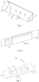
Fig. 1 is a structural schematic view of an antenna device according to an embodiment of the present application; -
Fig. 2 is a locally enlarged structural schematic view of an antenna device according to an embodiment of the present application; -
Fig. 3 is a structural schematic view of a support of an antenna device according to an embodiment of the present application; -
Fig. 4 is a structural schematic view of a support of an antenna device provided with an antenna assembly according to an embodiment of the present application; -
Fig. 5 is a sectional view of a support of an antenna device provided with an antenna assembly according to an embodiment of the present application; -
Fig. 6 is a structural schematic view of the support of the antenna device provided with the antenna assembly shown inFig. 4 from another perspective; -
Fig. 7 is a structural schematic view of a support of an antenna device according to an embodiment of the present application from another perspective; -
Fig. 8 is a locally structural schematic view of an antenna assembly of an antenna device according to an embodiment of the present application; -
Fig. 9 is a structural schematic view of a support of an antenna device according to another embodiment of the present application; -
Fig. 10 is a structural schematic view of a support of an antenna device provided with an antenna assembly according to another embodiment of the present application; -
Fig. 11 is a structural schematic view of a support of an antenna device according to another embodiment of the present application; -
Fig. 12 is a structural schematic view of a support of an antenna device according to another embodiment of the present application; -
Fig. 13 is a structural schematic view of a support of an antenna device according to another embodiment of the present application; -
Fig. 14 is a structural schematic view of a support of an antenna device according to another embodiment of the present application; -
Fig. 15 is a structural schematic view of a support of an antenna device according to another embodiment of the present application; -
Fig. 16 is a structural schematic view of a support of an antenna device provided with an antenna assembly according to another embodiment of the present application; and -
Fig. 17 is a structural schematic view of a support of an antenna device according to another embodiment of the present application. - Reference numerals:
- 10. antenna device;
- 100. frame; 110. border; 110a. sub-segment; 120. hollow space; 130. bottom plate;
- 200. support; 201. first end; 202. second end; 210. connecting via holes; 220. groove; 230. filling medium; 240. supporting portion; 250. contact portion; 260. second feeding portion; 270. conductive plate;
- 300. antenna assembly; 301. first antenna module; 302. second antenna module; 310. first antenna unit; 320. second antenna unit; 330. first integrated circuit; 340. first feeding portion; 350. carrying portion;
- 400. shielding cover;
- 500, connector; Y first direction; X. second direction; Z. third direction.
- Features and exemplary embodiments in various aspects of the present application will be described in detailed below. In the following detailed description, many specific details are presented to provide a comprehensive understanding of the present application. However, it is apparent to those skilled in the art that the present application can be implemented without requiring some of these specific details. The following description of the embodiments is merely intended to provide a better understanding of the present application by illustrating examples of the present application. At least some of the well-known structures and techniques are not shown in the drawings and the following description to avoid the unnecessary ambiguity in the present application. In addition, in order to clarity, the sizes of some structures may have been exaggerated. Moreover, the features, structures or characteristics described below may be combined in one or more embodiments in any suitable manner.
- In the description of the present application, it should be noted that, unless otherwise specified, "plurality" means more than two; the terms "upper", "lower", "left", "right", "inner", "outer", etc. indicate the orientation or positional relationship only for the convenience of describing the present application and simplifying the description, rather than indicating or implying that the device or the element referred to must have a specific orientation, be conFig.d and operated in a specific orientation, and therefore cannot be understood as a limitation of the present application. In addition, the terms "first", "second", etc. are only used for descriptive purposes, and cannot be understood as indicating or implying relative importance.
- The orientation words appearing in the following description are all directions shown in the drawings, and do not limit the specific structure of the present application. In the description of the present application, it should also be noted that, unless otherwise clearly specified and limited, the terms "installed", "connecting" and "connected" should be understood in a broad sense, for example, it can be a fixed connection, a detachable connection, or an integral connection, it can be a direct connection, or it can be an indirect connection. For those of ordinary skill in the art, the specific meaning of the above-mentioned terms in the present application can be understood according to specific situations.
- In order to better understand the present application, an antenna device and a wireless mobile terminal according to embodiments of the present application will be described in detail below with reference to
Fig. 1 to Fig. 17 . - Referring to
Fig. 1 to Fig. 4 ,Fig. 1 is a structural schematic view of an antenna device according to an embodiment of the present application;Fig. 2 is a locally enlarged structural schematic view of an antenna device according to an embodiment of the present application;Fig. 3 is a structural schematic view of a support of an antenna device according to an embodiment of the present application; andFig. 4 is a structural schematic view of a support provided with an antenna assembly. - As shown in
Fig. 1 andFig. 4 , in a first aspect, embodiments of the present application provide anantenna device 10. Theantenna device 10 includes aframe 100, asupport 200 and anantenna assembly 300. Theframe 100 includes aborder 110 and ahollow space 120 surrounded and formed by theborder 110; thesupport 200 is connected to theborder 110 and extending towards thehollow space 120; theantenna assembly 300 includes afirst antenna module 301 and asecond antenna module 302. Thefirst antenna module 301 is arranged on thesupport 200 and includes a plurality offirst antenna units 310 spaced apart from one another, and thesecond antenna module 302 includes a plurality ofsecond antenna units 320. Thefirst antenna module 301 and thesupport 200 are insulated from each other, and thesupport 200 includes a conductive material and is reused as at least a portion of thesecond antenna units 320. - In the
antenna device 10 provided in the present application, theantenna device 10 includes theframe 100, thesupport 200 and theantenna assembly 300. Theframe 100 can surround to form thehollow space 120 for theantenna assembly 300 and thesupport 200. Thesupport 200 is connected to theborder 110 and located in thehollow space 120 to provide an arranging position for theantenna assembly 300. Theantenna assembly 300 includes thefirst antenna module 301 and thesecond antenna module 302, which can improve the antenna function. When the antenna device is used for the wireless mobile terminal, the wireless communication performance of the wireless mobile terminal can be improved. Thefirst antenna module 301 includes the plurality offirst antenna units 310 arranged on thesupport 200, which can support thefirst antenna units 310. The support includes the conductive material and can be reused as at least a portion of thesecond antenna units 320, so as to further improve the function of thesupport 200 and reduce a space occupied by the entiresecond antenna module 302. - Optionally, the
antenna device 10 is used for the wireless mobile terminal. The wireless mobile terminal further include components such as a control board. The control board may be arranged in thehollow space 120. Optionally, theborder 110 may be a middle frame of the wireless mobile terminal, and theborder 110 is arranged to surround the wireless mobile terminal. - Optionally, the
border 110 may be integrally formed, that is, the closedannular border 110 which is integrally formed surrounds to form thehollow space 120. - In some other embodiments, the
border 110 may include a plurality of sub-segments 110a, which surround thehollow space 120. Optionally, each twoadjacent sub-segments 110a are insulated from each other, for example, an insulating spacer may be arranged between each twoadjacent sub-segments 110a to reduce the impact of theborder 110 on the wireless signal transmission of the wireless mobile terminal. The embodiments of the present application take theborder 110 including the plurality ofsub-segments 110a as an example to illustrate. - There are various arrangements of the
support 200, and thesupport 200 may be in a shape of plate, column or the like. Optionally, thesupport 200 is the shape of plate, so as to reduce a space occupied by thesupport 200 and facilitate theantenna assembly 300 arranging on thesupport 200. Optionally, theframe 100 further includes abottom plate 130, theborder 110 is connected to a peripheral side of thebottom plate 130, and theborder 110 and thebottom plate 130 jointly surround to form thehollow space 120. Optionally, a distance between a surface of thesupport 200 away from thebottom plate 130 and thebottom plate 130 is less than or equal to a distance between a surface of theborder 110 away from thebottom plate 130 and thebottom plate 130, that is, thesupport 200 is closer to thebottom plate 130 than theborder 110 to thebottom plate 130, and thesupport 200 does not protrude from theborder 110 in a direction away from thebottom plate 130, which can reduce an overall volume of theantenna device 10. - Optionally, the
bottom plate 130 and the control board of the wireless mobile terminal can be reused as each other. Alternatively, thebottom plate 130 and the control board can be separately arranged. - Optionally, the plurality of
first antenna units 310 can be arranged in a plurality of rows and columns on thesupport 200. Thefirst antenna units 310 of each two adjacent rows can be aligned or misaligned with each other. The embodiments of the present application take thefirst antenna units 310 arranged in a single row as an example. - There are various arrangements of the
first antenna module 301 and thesecond antenna module 302, for example, one of thefirst antenna module 301 and thesecond antenna module 302 is a millimeter wave antenna module, and the other is a non-millimeter wave antenna module, so that theantenna module 300 can transmit and receive millimeter wave signals and non-millimeter wave signals. - In some optional embodiments, the
first antenna module 301 is the millimeter wave antenna module, and thefirst antenna units 310 are used to transmit and receive the millimeter wave antenna signals. An arrangement size of each of thefirst antenna units 310 on thesupport 200 is flexible, so that it can be set to be smaller and more suitable to transmit and receive the millimeter wave antenna signals. Thesecond antenna module 302 is the non-millimeter wave antenna module, and thesecond antenna units 320 are used to transmit and receive the non-millimeter wave antenna signals. When thesecond antenna module 302 is the non-millimeter wave antenna module, an arrangement size of thesupport 200 that is reused as at least a portion of thesecond antenna units 320 can be set to be larger, so that thesupport 200 can support the plurality offirst antenna units 310. - In some optional embodiments, as described above, when the
frame 100 includes thebottom plate 130, thesupport 200 and thebottom plate 130 are spaced apart from each other, so that there is an arrangement space between thesupport 200 and thebottom plate 130. Thefirst antenna units 310 can be selectively arranged on the side of thesupport 200 facing or away from thebottom plate 130. - For example, in some embodiments, referring to
Fig. 1 to Fig. 5 , theantenna assembly 300 further includes a firstintegrated circuit 330. One of the firstintegrated circuit 330 and thefirst antenna units 310 is arranged on the side of thesupport 200 facing thebottom plate 130, the other is (are) arranged on the side of thesupport 200 away from thebottom plate 130, and the firstintegrated circuit 330 is electrically connected to thefirst antenna units 310. - In these optional embodiments, the first
integrated circuit 330 is electrically connected to thefirst antenna units 310, so that the firstintegrated circuit 330 can transmit the radio frequency signals to thefirst antenna units 310. The firstintegrated circuit 330 and thefirst antenna units 310 are arranged on two sides of thesupport 200, respectively. By utilizing the spaces at the two sides of thesupport 200, a spatial position occupied by theantenna assembly 300 can be further reduced, and a distance between the firstintegrated circuit 330 and thefirst antenna units 310 can be closer, so as to facilitate the electrical connection between the firstintegrated circuit 330 and thefirst antenna units 310. - In addition, since the
support 200 includes the conductive material, thesupport 200 has a good heat-dissipating effect. The firstintegrated circuit 330 does not require an additional heat sink component, that is, it is no need to provide an additional heat-dissipating metal to the firstintegrated circuit 330, so that it can reduce the cost of the heat sink component, save the occupied space, improve the compactness of the overall system design and achieve a better overall competitiveness. - Optionally, the first
integrated circuit 330 may include a first radio frequency integrated circuit and a first battery management integrated circuit. The first radio frequency integrated circuit is connected to thefirst antenna units 310, so as to transmit the radio frequency signals to thefirst antenna units 310. Optionally, the firstintegrated circuit 330 may include only the first radio frequency integrated circuit. - Optionally, the first
integrated circuit 330 is arranged on the side of thesupport 200 facing thebottom plate 130, and thefirst antenna units 310 are arranged on the side of thesupport 200 away from thebottom plate 130. Thefirst antenna units 310 are arranged further outward, which can reduce the impact of thesupport 200 on the signal transmission of thefirst antenna units 310 and enhance the signal transmission performance of thefirst antenna module 301. - Optionally, when the
first antenna units 310 are arranged on the side of thesupport 200 away from thebottom plate 130, a distance between surfaces of thefirst antenna units 310 away from thebottom plate 130 and thebottom plate 130 is less than or equal to the distance between the surface of theborder 110 away from thebottom plate 130 and thebottom plate 130, that is, thefirst antenna units 310 are closer to thebottom plate 130 than the surface of theborder 110 away from thebottom plate 130 to thebottom plate 130, and thefirst antenna units 310 do not protrude from theborder 110, which can further reduce the overall volume of theantenna device 10. - There are various ways to electrically connect the
first antenna units 310 with the firstintegrated circuit 330. For example, thefirst antenna module 301 includes afirst feeding portion 340, which is electrically connected to thefirst antenna units 310 and the firstintegrated circuit 330. Thefirst feeding portion 340 can be connected to thefirst antenna units 310 and the firstintegrated circuit 330 through an outer surface of thesupport 200, that is, thefirst feeding portion 340 is arranged on the outer surface of thesupport 200. - In some other optional embodiments, referring to
Fig. 1 to Fig.6 , thesupport 200 includes a connecting viahole 210 penetrating therethrough. At least a portion of thefirst feeding portion 340 is located in the connecting viahole 210 and electrically connected to thefirst antenna units 310 and the firstintegrated circuit 330, that is, thefirst feeding portion 340 is connected to thefirst antenna units 310 and the firstintegrated circuit 330 through the connecting viahole 210 inside thesupport 200. Thefirst feeding portion 340 does not occupy an external space of thesupport 200, which can further reduce the distance between thefirst antenna units 310 and the firstintegrated circuit 330, thereby reducing the path loss between thefirst antenna units 310 and the firstintegrated circuit 330, and further reducing a size of a space occupied by the antenna module. - Optionally, the
first antenna units 310 are electrically connected to the firstintegrated circuit 330 through thefirst feeding portion 340. In other embodiments, the number of thefirst feeding portions 340 connected to the samefirst antenna unit 310 is two or more, and the number of the connecting viaholes 210 is also two or more. Thefirst feeding portions 340 are located in the connecting viaholes 210, respectively. For example, the number of thefirst feeding portions 340 is equal to the number of connecting viahole 210, or the number of connecting viaholes 210 is larger than the number of thefirst feeding portions 340, so that thefirst feeding portions 340 can be connected to the firstintegrated circuit 330 and thefirst antenna units 310 through the connecting viaholes 210 at the appropriate positions. The number offirst feeding portions 340 connected to the samefirst antenna unit 310 is two or more, so as to facilitate the diversity transmission and reception of the wireless signals, reduce the probability of the wireless signal disconnection, facilitate the multiple-input multiple-output (MIMO) operation, and improve the wireless transmission rate. - There are various ways of the electrical connection between the first
integrated circuit 330 and thefirst feeding portions 340, and the firstintegrated circuit 330 can be directly connected to thefirst feeding portions 340. Alternatively, in some other optional embodiments, as shown inFig. 1 to Fig. 7 , theantenna assembly 300 further includes a carryingportion 350. The firstintegrated circuit 330 is arranged on the carryingportion 350, the carryingportion 350 is provided with a signal line, and the firstintegrated circuit 330 is electrically connected to thefirst feeding portions 340 through the signal line, that is, the signal line is electrically connected between the firstintegrated circuit 330 and thefirst feeding portions 340. - There are various arrangements of the carrying
portion 350. Optionally, the carryingportion 350 may be a flexible substrate, and a material of the carryingportion 350 may include a flexible material such as polyimide, which can facilitate the carryingportion 350 being attached to thesupport 200. - In some optional embodiments, the
support 200 is provided with agroove 220, and thefirst antenna units 310 are located in thegroove 220. Thegroove 220 can provide the positioning and limiting functions to thefirst antenna units 310. Thegroove 220 can form a reflector for thefirst antenna units 310, which can facilitate reflecting the antenna radiation beams of thefirst antenna units 310 outward and improving the performance of thefirst antenna module 301. - Optionally, two or more
first antenna units 310 which are stacked can be arranged in thesame groove 220. - There are various arrangements of the
groove 220, as shown inFig. 9 , the number of thegroove 220 may be one, and onegroove 220 extends in an extending direction of thesupport 200. The plurality offirst antenna units 310 may be located in thesame groove 220, so that the implementation process can be simple, and the implementation cost can be reduced. - In some other optional embodiments, as shown in
Fig. 1 to Fig. 10 , the number of thegrooves 220 can be two or more, a plurality ofgrooves 220 are spaced apart from one another. Thefirst antenna units 310 are located in thegrooves 220, respectively, so that thegrooves 220 can provide the positioning and limiting functions to thefirst antenna units 310, respectively. In addition, thefirst antenna units 310 are located in thegrooves 220, respectively, so that the isolation among thefirst antenna units 310 can increase, the performance of the antenna can be improved, and the quality of the wireless communication can be improved. - Optionally, when the
support 200 is provided with the connecting viahole 210, the connecting viahole 210 can be located in thegroove 220, that is, the connecting viahole 210 communicates with thegroove 220. On one hand, a thickness of thesupport 200 where thegroove 220 is located is relatively small, so as to facilitate the processing and forming of the connecting viahole 210; on the other hand, thefirst antenna units 310 are arranged in thegroove 220, and the connecting viahole 210 is provided in thegroove 220, so that a distance between the connecting viahole 210 and thefirst antenna units 310 can be further shorten. - Optionally, when there are the plurality of
grooves 220 and the plurality offirst feeding portions 340 connected to the samefirst antenna unit 310, the plurality of connecting viaholes 210 can be provided in thesame groove 220. - Optionally, as shown in
Fig. 9 andFig. 10 , a fillingmedium 230 is provided between thefirst antenna units 310 and an inner wall face of thegroove 220, so as to ensure the stability of the positions of thefirst antenna units 310. The fillingmedium 230, for example, may be at least one of fluorine material or liquid crystal polymer. Alternatively, the fillingmedium 230 may be adhesive, ceramic powder or other materials. - In some optional embodiments, the
antenna device 10 further includes a shielding cover 400, which covers on a side of the firstintegrated circuit 330 away from thesupport 200, and the shielding cover 400 and thesupport 200 jointly surround to form a cavity for accommodating the firstintegrated circuit 330. - In these optional embodiments, the
antenna device 10 is further provided with the shielding cover 400, the shielding cover 400 and thesupport 200 jointly surround to form the cavity, and the firstintegrated circuit 330 is located in the cavity, so that thesupport 200 and the shielding cover 400 can provide the comprehensive protection to the firstintegrated circuit 330, reduce the electromagnetic interference to the firstintegrated circuit 330 from the external environment or the electromagnetic interference from the firstintegrated circuit 330 to the external environment, and provide waterproof, dustproof, anti-collision and other protections for the firstintegrated circuit 330. - When the
antenna assembly 300 further includes the carryingportion 350, the shielding cover 400 and the carryingportion 350 jointly surround to form the cavity that accommodates the firstintegrated circuit 330. - Optionally, the
antenna assembly 300 further includes aconnector 500, which is arranged on thesupport 200 and connected to the firstintegrated circuit 330, so that the firstintegrated circuit 330 can be electrically connected to the outer side through theconnector 500 to perform the signal transmission. Theconnector 500 and the firstintegrated circuit 330 are spaced apart from each other on the same side of thesupport 200, and theconnector 500 and the shielding cover 400 are spaced apart from each other in the extending direction of thesupport 200. - In these optional embodiments, the first
integrated circuit 330 can be electrically connected to the outer side through theconnector 500, for example, the firstintegrated circuit 330 can be electrically connected to the control board of the wireless mobile terminal through theconnector 500. Theconnector 500 and the firstintegrated circuit 330 are arranged on the same side of thesupport 200, so as to reduce a distance between theconnector 500 and the firstintegrated circuit 330, facilitate the electrical connection between the firstintegrated circuit 330 and theconnector 500. Theconnector 500 and the shielding cover 400 are spaced apart from each other in the extending direction of thesupport 200. In the case that the shielding cover 400 is continued to be arranged after the firstintegrated circuit 330 is arranged, the situation where the shielding cover 400 is not placed correctly and collides with theconnector 500 can be avoided. - Optionally, the plurality of sub-segments 110a of the
border 110 include two first sub-segments extending in a first direction Y and spaced apart from each other and two second sub-segments extending in a second direction X and spaced apart from each other. The two first sub-segments and the two second sub-segments are surround and alternately connected in end-to-end to form thehollow space 120. Thesupport 200 can be connected to the first sub-sections and/or the second sub-sections. Optionally, when thesupport 200 is connected to one of the two second sub-segments, the extending direction of thesupport 200 is a spacing direction between the two first sub-segments, that is, the extending direction of thesupport 200 is the first direction Y. When thesupport 200 is connected to one of the two first sub-segments, the extending direction of thesupport 200 is the second direction X. - In some optional embodiments, the
support 200 is provided with a supportingportion 240. The supportingportion 240 extends from thesupport 200 towards thebottom plate 130 and is connected between thesupport 200 and thebottom plate 130. The supportingportion 240 support and is connected between thesupport 200 and thebottom plate 130, so as to ensure the stability of the position of thesupport 200. - Optionally, the
support 200 includes afirst end 201 and asecond end 202 that are opposite to each other. Thefirst end 201 is connected to theborder 110, and thesecond end 202 is connected to the supportingportion 240. The supportingportion 240 extends from thesecond end 202 towards thebottom plate 130 and is connected between thesecond end 202 and thebottom plate 130. - In these optional embodiments, the
first end 201 of thesupport 200 is connected to theborder 110, thesecond end 202 away from thefirst end 201 is connected to the supportingportion 240, and the supportingportion 240 supports and is connected between thesecond end 202 and thebottom plate 130, so as to ensure the stability of the position of thesupport 200. - In some other embodiments, the supporting
portion 240 can be arranged at any position of thesupport 200. - There are various arrangements of the supporting
portion 240, for example, the supportingportion 240 may be in a shape of column, further, the supportingportion 240 may be in a shape of cylinder, prism or the like. The supportingportion 240 can be set with equal cross-sections in a direction from thesupport 200 to thebottom plate 130. - In some other optional embodiments, a cross-section of the supporting
portion 240 gradually decreases in the direction from thesupport 200 to thebottom plate 130, which is conducive to matching the impedance of thesecond antenna module 302, conducive to improving the antenna performance and conducive to enhancing the structural stability. - Optionally, the
bottom plate 130 includes a ground layer, thesupport 200 is electrically connected to the supportingportion 240, and the supportingportion 240 is electrically connected to the ground layer, so that the supportingportion 240 can be grounded through the ground layer of thebottom plate 130. Thesupport 200 is reused as at least a portion of thesecond antenna units 320, so that thesecond antenna units 320 can be electrically connected through the ground layer of thesupport 200, the supportingportion 240 and thebottom plate 130. - In other embodiments, as shown in
Fig. 11 , the supportingportion 240 may not be provided on thesupport 200, and theborder 110 is provided with a ground portion. Thesupport 200 and the ground portion on theborder 110 are connected to each other, that is, thesupport 200 which is reused as at least a portion of thesecond antenna units 320 is connected to theborder 110, so as to achieve the grounding of thesecond antenna units 320. For example, when theborder 110 includes the sub-segment 110a, the sub-segment 110a is provided with the ground portion, and thesupport 200 and the sub-segment 110a are connected to each other. - In some optional embodiments, as described above, when the
border 110 includes the plurality of sub-segments 110a, at least one of the sub-segments 110a includes a conductive material and is reused as at least a portion of thesecond antenna units 320. Thefirst end 201 of thesupport 200 is electrically connected to thesub-segments 110a reused as thesecond antenna units 320. - In these optional embodiments, at least a portion of the
sub-segments 110a are reused as a portion of thesecond antenna units 320, which can further improve a distribution area of thesecond antenna module 302 and improve the wireless communication performance of thesecond antenna module 302. Thefirst end 201 of thesupport 200 is electrically connected to thesub-segments 110a reused as thesecond antenna units 320, so that thesupport 200 and thesub-segments 110a can be jointly reused as thesecond antenna units 320, and the structure of thesecond antenna units 320 can be simplified. - In some optional embodiments, as shown in
Fig. 10 to Fig. 13 , thefirst end 201 of thesupport 200 can be directly connected and in contact with theborder 110, that is, thesupport 200 is directly connected and in contact with thesub-segments 110a reused as thesecond antenna units 320, and a contact area between thesupport 200 and the sub-segments 110a is a cross-sectional area of thesupport 200. Thesupport 200 has nocontact portion 250, so thesupport 200 can be further away from themetal bottom plate 130, which can improve the antenna performance of thesecond antenna units 320, and occupies a relatively small area on thebottom plate 130. - In other embodiments, as shown in
Fig. 14 to Fig. 17 , thefirst end 201 is provided with acontact portion 250. Thecontact portion 250 extends from thefirst end 201 towards thebottom plate 130 and is connected to theborder 110. Thecontact portion 250 can increase the contact area between thesupport 200 and the sub-segments 110a of theborder 110, ensure the stability of the position of thesupport 200, and reduce the resistance. - Optionally, when the
support 200 is connected to the ground portion of theborder 110, thesupport 200 can be directly connected to the ground portion of theborder 110. A conductive portion is exposed from a cross-section of thesupport 200 facing theborder 110, and thesupport 200 is connected to the ground portion of theborder 110 through the conductive portion. Alternatively, thesupport 200 can be connected to the ground portion of theborder 110 through thecontact portion 250. - Optionally, the
contact portion 250 and thesupport 200 can be integrally formed, so as to simplify the structure of theantenna device 10. - Optionally, an end of the
contact portion 250 away from thefirst end 201 is connected to thebottom plate 130, so as to further ensure the stability of the position of thesupport 200. - Optionally, the
antenna assembly 300 further includes asecond feeding portion 260. Thesecond feeding portion 260 is electrically connected to thesupport 200, so that thesecond antenna units 320 can be fed in through thesecond feeding portion 260. - Optionally, the supporting
portion 240 as described above can be reused as thesecond feeding portion 260, in this case, the supportingportion 240 is not electrically connected to the ground layer of thebottom plate 130. For example, when thebottom plate 130 and the control board are reused, a second integrated circuit is arranged on thebottom plate 130, thesecond feeding portion 260 can be electrically connected to the second integrated circuit on thebottom plate 130, and the supportingportion 240 reused as thesecond feeding portion 260 can be electrically connected to the second integrated circuit. - In some other embodiments, the
second feeding portion 260 and the supportingportion 240 are spaced apart from each other on thesupport 200. Thesecond feeding portion 260 can be electrically connected to the second integrated circuit as described above, the supportingportion 240 can be electrically connected to the ground layer, and thesecond feeding portion 260 and the supportingportion 240 are respectively used to achieve different functions. - Optionally, the number of the supporting
portions 240 is two or more, and a plurality of supportingportions 240 are spaced apart from one another on thesupport 200; and/or, the number of thesecond feeding portions 260 is two or more, and a plurality ofsecond feeding portions 260 are spaced apart from one another. - Optionally, the
second feeding portion 260 may be arranged on the side of thesupport 200 facing thebottom plate 130, and the second feeding portion extends from thesupport 200 towards thebottom plate 130, so as to utilize a gap between thesupport 200 and thebottom plate 130 to arrange thesecond feeding portion 260 and reduce the overall structural size of theantenna device 10. - Optionally, the
second feeding portion 260 is connected to thebottom plate 130, that is, thesecond feeding portion 260 is connected between thebottom plate 130 and thesupport 200, which can further improve the structural stability of thesupport 200. - Optionally, as shown in
Fig. 14 , in a direction from thebottom plate 130 to thesupport 200, a cross-sectional area of thesecond feeding portion 260 gradually increases, which is conducive to matching the input impedance of a non-millimeter wave antenna, can allow the energy fed into thesecond feeding portion 260 to radiate to a larger extent, and can improve the antenna performance and the wireless communication quality of the non-millimeter wave antenna. - Optionally, as shown in
Fig. 15 , thesecond feeding portion 260 can be formed by extending along a bending path, so as to increase a length of an extending path of thesecond feeding portion 260, improve the inductance performance of thesecond feeding portion 260, facilitate matching the impedance, and allow the energy fed into thesecond feeding portion 260 to radiate out to a larger extent. In addition, the length of thesecond antenna module 302 can be extended, so as to better cover the lower frequency band in the case of the same appearance (such as the same number and position of metal gaps). - Optionally, as shown in
Fig. 16 , thesecond feeding portion 260 is connected to aconductive plate 270. Theconductive plate 270 includes an adjustment plane facing thebottom plate 130, and the adjustment plane intersects with a spacing direction between thebottom plate 130 and thesupport 200. For example, thebottom plate 130 and thesupport 200 are spaced apart from each other in a third direction Z, and the adjustment plane intersects with the third direction Z. By arranging theconductive plate 270, a parasitic capacitance is formed between theconductive plate 270 and the ground layer of thebottom plate 130, which is conducive to matching the impedance of the non-millimeter wave, can allow the energy fed into thesecond feeding portion 260 to radiate to a larger extent, and can improve the antenna performance and the wireless communication quality of the non-millimeter wave antenna. - Optionally, as shown in
Fig. 17 , thesecond feeding portion 260 extends along the bending path, and theconductive plate 270 can be arranged on thesecond feeding portion 260, so as to adjust the capacitance and the inductance characteristics of the input impedance of the non-millimeter wave antenna with higher degrees of freedom, make the input impedance more matched, allow the energy fed into thesecond feeding portion 260 to radiate to a larger extent, and improve the antenna performance and wireless communication quality of the non-millimeter wave antenna. - Optionally, the
second feeding portion 260 may include a straight segment and a bending segment distributed in the third direction Z (i.e., the spacing direction between thesupport 200 and the bottom plate 130). When theconductive plate 270 is connected to thesecond feeding portion 260, theconductive plate 270 may be located on a side of the bending segment facing or away from thebottom plate 130. The straight segment may also be located on the side of the bending segment facing or away from thebottom plate 130. - Optionally, as shown in
Fig. 11 , thesupport 200 may be not provided with the supportingportion 240 and thesecond feeding portion 260, so as to minimize an occupied area of thesupport 200, allow thesupport 200 to become another branch of thesecond antenna module 302 to cover the new non-millimeter wave frequency band, and facilitate achieving the design of a multi-frequency non-millimeter wave antenna. - Optionally, as shown in
Fig. 12 , thesupport 200 may be provided with the supportingportion 240 without thesecond feeding portion 260. Alternatively, in some other embodiments, as shown inFig. 13 , thesupport 200 may be provided with thesecond feeding portion 260 without the supportingportion 240, and thesecond feeding portion 260 has the functions of feeding and supporting. - In a second aspect, embodiments of the present application provide a wireless mobile terminal including the
antenna device 10 according to any one of the above embodiments in the first aspect. Since the wireless mobile terminal provided by the embodiments of the present application in the second aspect includes theantenna device 10 according to any one of the above embodiments in the first aspect, the wireless mobile terminal provided by the embodiments of the present application in the second aspect has the beneficial effects of theantenna device 10 according to any one of the above embodiments in the first aspect, which will not be repeated here. - The wireless mobile terminal in the embodiments of the present application includes but is not limited to a device with the wireless communication function, such as a mobile phones, a personal digital assistants (PDA), a tablet, an e-books, a television, an access control, a smart landline phone or a console.
- Although the present disclosure has been described with reference to the preferred embodiments, various modifications may be made to the present disclosure and components may be replaced with equivalents without departing from the scope of the present disclosure. In particular, the technical features mentioned in the various embodiments can be combined in any manner as long as there is no structural conflict. The present disclosure is not limited to the specific embodiments disclosed herein, but includes all technical solutions falling within the scope of the claims.
Claims (15)
- An antenna device, comprising:a frame (100), comprising a border (110) and a hollow space (120) surrounded and formed by the border (110);wherein the antenna device is characterized by comprising:a support (200), connected to the border (110) and extending towards the hollow space (120); andan antenna assembly (300), comprising a first antenna module (301) and a second antenna module (302), the first antenna module (301) being arranged on the support (200) and comprising a plurality of first antenna units (310) spaced apart from one another, and the second antenna module (302) comprising a plurality of second antenna units (320),the first antenna module (301) and the support (200) being insulated from each other, and the support (200) comprising a conductive material and being reused as at least a portion of the second antenna units (320).
- The antenna device according to claim 1, characterized in that the first antenna module (301) is a millimeter wave antenna module, and the first antenna units (310) are configured to transmit and receive a millimeter wave antenna signal;
the second antenna module (302) is a non-millimeter wave antenna module, and the second antenna units (320) are configured to transmit and receive a non-millimeter wave antenna signal. - The antenna device according to claim 1, characterized in that the frame (100) further comprises a bottom plate (130), the bottom plate (130) is connected to the border (110), the bottom plate (130) and the border (110) jointly surround to form the hollow space (120), and the support (200) and the bottom plate (130) are spaced apart from each other; and
the border (110) is provided with a ground portion, and the support (200) is connected to the ground portion. - The antenna device according to claim 3, characterized in that the antenna assembly (300) further comprises a first integrated circuit (330), one of the first integrated circuit (330) and the first antenna units (310) is arranged on a side of the support (200) facing the bottom plate (130), another of the first integrated circuit (330) and the first antenna units (310) is arranged on a side of the support (200) away from the bottom plate (130), and the first integrated circuit (330) is electrically connected to the first antenna units (310).
- The antenna device according to claim 4, characterized in that the support (200) comprises a connecting via hole (210) penetrating therethrough, and the first antenna module (301) comprises a first feeding portion (340), at least a portion of the first feeding portion (340) is located in the connecting via hole (210), and the first feeding portion (340) is electrically connected to the first antenna units (310) and the first integrated circuit (330);the antenna assembly (300) further comprises a carrying portion (350), the first integrated circuit (330) is arranged on the carrying portion (350), the carrying portion (350) is provided with a signal line, and the first integrated circuit (330) is electrically connected to the first feeding portion (340) through the signal line;the support (200) is provided with a groove (220), and the first antenna units (310) are located in the groove (220);the connecting via hole (210) is located in the groove (220); anda filling medium (230) is provided between the first antenna units (310) and inner wall faces of the groove (220).
- The antenna device according to claim 5, characterized in that the first antenna module (301) comprises two or more first feeding portions (340) connected to the same first antenna unit (310), the support (200) comprises two or more connecting via holes (210), and the first feeding portions (340) correspond to the connecting via holes (210), respectively;the support (200) is provided with a plurality of grooves (220) spaced apart from one another, and the first antenna units (310) correspond to the grooves (220), respectively; andthe connecting via holes (210) are located in the grooves (220).
- The antenna device according to claim 4, characterized by further comprising a shielding cover (400), wherein the shielding cover (400) is arranged to cover on a side of the first integrated circuit (330) away from the support (200), and the shielding cover (400) and the support (200) jointly surround to form a cavity for accommodating the first integrated circuit (330).
- The antenna device according to claim 7, characterized in that the antenna assembly (300) further comprises a connector (500), the connector (500) is arranged on the support (200) and connected to the first integrated circuit (330), the first integrated circuit (330) is electrically connected to an outer side through the connector (500), the connector (500) and the first integrated circuit (330) are spaced apart from each other on the same side of the support (200), and the connector (500) and the shielding cover (400) are spaced apart from each other in an extending direction of the support (200).
- The antenna device according to claim 3, characterized in that the support (200) is provided with a supporting portion (240), and the supporting portion (240) extends from the support (200) towards the bottom plate (130) and is connected to the bottom plate (130).
- The antenna device according to claim 9, characterized in that the support (200) comprises a first end (201) and a second end (202) opposite to each other, the first end (201) is connected to the border (110), the second end (202) is connected to the supporting portion (240), and the supporting portion (240) extends from the second end (202) towards the bottom plate (130) and is connected to the bottom plate (130);a cross-section of the supporting portion (240) gradually decreases in a direction from the support (200) to the bottom plate (130); andthe bottom plate (130) comprises a ground layer, the support (200) is electrically connected to the supporting portion (240), and the supporting portion (240) is electrically connected to the ground layer.
- The antenna device according to claim 10, characterized in that the frame (100) comprises a plurality of sub-segments (110a) arranged around the hollow space (120) and spaced apart from one another, at least one of the sub-segments (110a) comprises a conductive material and is reused as at least a portion of the second antenna units (320), and the first end (201) of the support (200) is electrically connected to the at least one of the sub-segments (110a) reused as the at least a portion of the second antenna units (320).
- The antenna device according to claim 11, characterized in that the support (200) is directly connected to the border (110) through the first end (201);
or the first end (201) is provided with a contact portion (250), and the contact portion (250) extends from the first end (201) towards the bottom plate (130) and is connected to the border (110). - The antenna device according to claim 11, characterized in that the support (200) is provided with a second feeding portion (260), and the second feeding portion (260) is electrically connected to the support (200).
- The antenna device according to claim 13, characterized in that the second feeding portion (260) is arranged on the side of the support (200) facing the bottom plate (130), and the second feeding portion (260) extends from the support (200) towards the bottom plate (130);the second feeding portion (260) is connected to the bottom plate (130);the second feeding portion (260) and the supporting portion (240) are reused as each other, or the second feeding portion (260) and the supporting portion (240) are spaced apart from each other;an area of a cross-section of the second feeding portion (260) gradually decreases in the direction from the support (200) to the bottom plate (130);the second feeding portion (260) extends along a bending path;the second feeding portion (260) is provided with and connected to a conductive plate (270), the conductive plate (270) comprises an adjustment plane facing the bottom plate (130), and the adjustment plane intersects with a spacing direction between the bottom plate (130) and the support (200).
- A wireless mobile terminal, characterized by comprising the antenna device (10) according to any one of claims 1 to 14.
Applications Claiming Priority (1)
| Application Number | Priority Date | Filing Date | Title |
|---|---|---|---|
| CN202311542521.5A CN117410674B (en) | 2023-11-17 | 2023-11-17 | Antenna device and wireless mobile terminal |
Publications (1)
| Publication Number | Publication Date |
|---|---|
| EP4557507A1 true EP4557507A1 (en) | 2025-05-21 |
Family
ID=89488996
Family Applications (1)
| Application Number | Title | Priority Date | Filing Date |
|---|---|---|---|
| EP24209027.2A Pending EP4557507A1 (en) | 2023-11-17 | 2024-10-25 | Antenna device and wireless mobile terminal |
Country Status (5)
| Country | Link |
|---|---|
| US (1) | US20250023256A1 (en) |
| EP (1) | EP4557507A1 (en) |
| JP (1) | JP2025082810A (en) |
| KR (1) | KR20240157589A (en) |
| CN (1) | CN117410674B (en) |
Families Citing this family (1)
| Publication number | Priority date | Publication date | Assignee | Title |
|---|---|---|---|---|
| CN118783081B (en) * | 2024-07-31 | 2025-10-28 | 云谷(固安)科技有限公司 | Antenna device and wireless mobile terminal |
Citations (1)
| Publication number | Priority date | Publication date | Assignee | Title |
|---|---|---|---|---|
| US20220109228A1 (en) * | 2021-11-16 | 2022-04-07 | Etheta Communication Technology (Shenzhen) Co., Ltd. | Antenna device and electronic apparatus |
Family Cites Families (7)
| Publication number | Priority date | Publication date | Assignee | Title |
|---|---|---|---|---|
| JP2019054315A (en) * | 2016-04-28 | 2019-04-04 | 日本電産エレシス株式会社 | Mounting board, waveguide module, integrated circuit mounting board, microwave module, radar device and radar system |
| KR102500361B1 (en) * | 2018-07-26 | 2023-02-16 | 삼성전자주식회사 | An electronic device comprising a 5g antenna module |
| KR102526400B1 (en) * | 2018-09-06 | 2023-04-28 | 삼성전자주식회사 | An electronic device comprising a 5g antenna module |
| CN112993515B (en) * | 2019-12-16 | 2023-10-03 | RealMe重庆移动通信有限公司 | Wearable electronic equipment |
| CN112216958B (en) * | 2020-09-30 | 2022-11-18 | 维沃移动通信有限公司 | Electronic device |
| CN113809513B (en) * | 2021-11-16 | 2022-02-15 | 深圳市睿德通讯科技有限公司 | Antenna device and electronic apparatus |
| CN114530694B (en) * | 2022-04-24 | 2022-07-05 | 云谷(固安)科技有限公司 | Wireless communication structure, display panel and wireless communication device |
-
2023
- 2023-11-17 CN CN202311542521.5A patent/CN117410674B/en active Active
-
2024
- 2024-09-30 US US18/901,586 patent/US20250023256A1/en active Pending
- 2024-10-15 KR KR1020240140111A patent/KR20240157589A/en active Pending
- 2024-10-15 JP JP2024179788A patent/JP2025082810A/en active Pending
- 2024-10-25 EP EP24209027.2A patent/EP4557507A1/en active Pending
Patent Citations (1)
| Publication number | Priority date | Publication date | Assignee | Title |
|---|---|---|---|---|
| US20220109228A1 (en) * | 2021-11-16 | 2022-04-07 | Etheta Communication Technology (Shenzhen) Co., Ltd. | Antenna device and electronic apparatus |
Non-Patent Citations (1)
| Title |
|---|
| HUANG HUAN-CHU ET AL: "Millimeter-wave and Microwave Integrated Antennas for Cell Phones", 2023 CROSS STRAIT RADIO SCIENCE AND WIRELESS TECHNOLOGY CONFERENCE (CSRSWTC), IEEE, 10 November 2023 (2023-11-10), pages 1 - 3, XP034547522, DOI: 10.1109/CSRSWTC60855.2023.10427351 * |
Also Published As
| Publication number | Publication date |
|---|---|
| KR20240157589A (en) | 2024-11-01 |
| CN117410674A (en) | 2024-01-16 |
| JP2025082810A (en) | 2025-05-29 |
| US20250023256A1 (en) | 2025-01-16 |
| CN117410674B (en) | 2024-06-14 |
Similar Documents
| Publication | Publication Date | Title |
|---|---|---|
| JP7130164B2 (en) | Displays, display devices and electronic devices with integrated antennas | |
| US11962099B2 (en) | Antenna structure and high-frequency multi-band wireless communication terminal | |
| US11909098B2 (en) | Antenna structure and high-frequency wireless communications terminal | |
| JP7480341B2 (en) | Antenna module and electronic device | |
| US12500330B2 (en) | Patch antenna and electronic device | |
| US11329367B2 (en) | Antenna device and electronic apparatus | |
| EP3828998B1 (en) | Terminal device | |
| CN115332786A (en) | Antenna device and electronic equipment | |
| US7109948B2 (en) | Dielectric antenna module | |
| CN111864362A (en) | Antenna modules and electronic equipment | |
| CN111162371B (en) | Electronic equipment | |
| US12107321B2 (en) | Antenna and electronic device including same | |
| US20250023256A1 (en) | Antenna device and wireless mobile terminal | |
| JP2019134403A (en) | Chip antenna and chip antenna module including the same | |
| CN111864343A (en) | Electronic equipment | |
| CN117673700B (en) | Antenna device and wireless electronic device | |
| US20250343348A1 (en) | Antenna apparatus and wireless mobile terminal | |
| US20250062522A1 (en) | Antenna assembly, housing and mobile terminal | |
| US11871507B2 (en) | Electronic device | |
| US20250070451A1 (en) | Antenna device, housing and electronic apparatus | |
| WO2025241932A9 (en) | Antenna unit, antenna, antenna system and base station |
Legal Events
| Date | Code | Title | Description |
|---|---|---|---|
| PUAI | Public reference made under article 153(3) epc to a published international application that has entered the european phase |
Free format text: ORIGINAL CODE: 0009012 |
|
| STAA | Information on the status of an ep patent application or granted ep patent |
Free format text: STATUS: REQUEST FOR EXAMINATION WAS MADE |
|
| 17P | Request for examination filed |
Effective date: 20241025 |
|
| AK | Designated contracting states |
Kind code of ref document: A1 Designated state(s): AL AT BE BG CH CY CZ DE DK EE ES FI FR GB GR HR HU IE IS IT LI LT LU LV MC ME MK MT NL NO PL PT RO RS SE SI SK SM TR |