EP4557488A1 - Battery and electric device - Google Patents
Battery and electric device Download PDFInfo
- Publication number
- EP4557488A1 EP4557488A1 EP22951490.6A EP22951490A EP4557488A1 EP 4557488 A1 EP4557488 A1 EP 4557488A1 EP 22951490 A EP22951490 A EP 22951490A EP 4557488 A1 EP4557488 A1 EP 4557488A1
- Authority
- EP
- European Patent Office
- Prior art keywords
- space
- battery
- pressure relief
- box
- exhaust gases
- Prior art date
- Legal status (The legal status is an assumption and is not a legal conclusion. Google has not performed a legal analysis and makes no representation as to the accuracy of the status listed.)
- Pending
Links
Images



Classifications
-
- H—ELECTRICITY
- H01—ELECTRIC ELEMENTS
- H01M—PROCESSES OR MEANS, e.g. BATTERIES, FOR THE DIRECT CONVERSION OF CHEMICAL ENERGY INTO ELECTRICAL ENERGY
- H01M10/00—Secondary cells; Manufacture thereof
- H01M10/42—Methods or arrangements for servicing or maintenance of secondary cells or secondary half-cells
- H01M10/425—Structural combination with electronic components, e.g. electronic circuits integrated to the outside of the casing
-
- H—ELECTRICITY
- H01—ELECTRIC ELEMENTS
- H01M—PROCESSES OR MEANS, e.g. BATTERIES, FOR THE DIRECT CONVERSION OF CHEMICAL ENERGY INTO ELECTRICAL ENERGY
- H01M10/00—Secondary cells; Manufacture thereof
- H01M10/42—Methods or arrangements for servicing or maintenance of secondary cells or secondary half-cells
- H01M10/48—Accumulators combined with arrangements for measuring, testing or indicating the condition of cells, e.g. the level or density of the electrolyte
-
- H—ELECTRICITY
- H01—ELECTRIC ELEMENTS
- H01M—PROCESSES OR MEANS, e.g. BATTERIES, FOR THE DIRECT CONVERSION OF CHEMICAL ENERGY INTO ELECTRICAL ENERGY
- H01M10/00—Secondary cells; Manufacture thereof
- H01M10/60—Heating or cooling; Temperature control
- H01M10/61—Types of temperature control
- H01M10/613—Cooling or keeping cold
-
- H—ELECTRICITY
- H01—ELECTRIC ELEMENTS
- H01M—PROCESSES OR MEANS, e.g. BATTERIES, FOR THE DIRECT CONVERSION OF CHEMICAL ENERGY INTO ELECTRICAL ENERGY
- H01M10/00—Secondary cells; Manufacture thereof
- H01M10/60—Heating or cooling; Temperature control
- H01M10/63—Control systems
-
- H—ELECTRICITY
- H01—ELECTRIC ELEMENTS
- H01M—PROCESSES OR MEANS, e.g. BATTERIES, FOR THE DIRECT CONVERSION OF CHEMICAL ENERGY INTO ELECTRICAL ENERGY
- H01M50/00—Constructional details or processes of manufacture of the non-active parts of electrochemical cells other than fuel cells, e.g. hybrid cells
- H01M50/30—Arrangements for facilitating escape of gases
-
- H—ELECTRICITY
- H01—ELECTRIC ELEMENTS
- H01M—PROCESSES OR MEANS, e.g. BATTERIES, FOR THE DIRECT CONVERSION OF CHEMICAL ENERGY INTO ELECTRICAL ENERGY
- H01M50/00—Constructional details or processes of manufacture of the non-active parts of electrochemical cells other than fuel cells, e.g. hybrid cells
- H01M50/30—Arrangements for facilitating escape of gases
- H01M50/317—Re-sealable arrangements
-
- H—ELECTRICITY
- H01—ELECTRIC ELEMENTS
- H01M—PROCESSES OR MEANS, e.g. BATTERIES, FOR THE DIRECT CONVERSION OF CHEMICAL ENERGY INTO ELECTRICAL ENERGY
- H01M50/00—Constructional details or processes of manufacture of the non-active parts of electrochemical cells other than fuel cells, e.g. hybrid cells
- H01M50/30—Arrangements for facilitating escape of gases
- H01M50/35—Gas exhaust passages comprising elongated, tortuous or labyrinth-shaped exhaust passages
-
- H—ELECTRICITY
- H01—ELECTRIC ELEMENTS
- H01M—PROCESSES OR MEANS, e.g. BATTERIES, FOR THE DIRECT CONVERSION OF CHEMICAL ENERGY INTO ELECTRICAL ENERGY
- H01M50/00—Constructional details or processes of manufacture of the non-active parts of electrochemical cells other than fuel cells, e.g. hybrid cells
- H01M50/30—Arrangements for facilitating escape of gases
- H01M50/35—Gas exhaust passages comprising elongated, tortuous or labyrinth-shaped exhaust passages
- H01M50/358—External gas exhaust passages located on the battery cover or case
-
- H—ELECTRICITY
- H01—ELECTRIC ELEMENTS
- H01M—PROCESSES OR MEANS, e.g. BATTERIES, FOR THE DIRECT CONVERSION OF CHEMICAL ENERGY INTO ELECTRICAL ENERGY
- H01M50/00—Constructional details or processes of manufacture of the non-active parts of electrochemical cells other than fuel cells, e.g. hybrid cells
- H01M50/30—Arrangements for facilitating escape of gases
- H01M50/35—Gas exhaust passages comprising elongated, tortuous or labyrinth-shaped exhaust passages
- H01M50/367—Internal gas exhaust passages forming part of the battery cover or case; Double cover vent systems
-
- H—ELECTRICITY
- H01—ELECTRIC ELEMENTS
- H01M—PROCESSES OR MEANS, e.g. BATTERIES, FOR THE DIRECT CONVERSION OF CHEMICAL ENERGY INTO ELECTRICAL ENERGY
- H01M50/00—Constructional details or processes of manufacture of the non-active parts of electrochemical cells other than fuel cells, e.g. hybrid cells
- H01M50/30—Arrangements for facilitating escape of gases
- H01M50/383—Flame arresting or ignition-preventing means
-
- Y—GENERAL TAGGING OF NEW TECHNOLOGICAL DEVELOPMENTS; GENERAL TAGGING OF CROSS-SECTIONAL TECHNOLOGIES SPANNING OVER SEVERAL SECTIONS OF THE IPC; TECHNICAL SUBJECTS COVERED BY FORMER USPC CROSS-REFERENCE ART COLLECTIONS [XRACs] AND DIGESTS
- Y02—TECHNOLOGIES OR APPLICATIONS FOR MITIGATION OR ADAPTATION AGAINST CLIMATE CHANGE
- Y02E—REDUCTION OF GREENHOUSE GAS [GHG] EMISSIONS, RELATED TO ENERGY GENERATION, TRANSMISSION OR DISTRIBUTION
- Y02E60/00—Enabling technologies; Technologies with a potential or indirect contribution to GHG emissions mitigation
- Y02E60/10—Energy storage using batteries
Definitions
- the present application relates to the field of battery technologies, and in particular, to a battery and an electrical device.
- batteries are increasingly widely used, such as in mobile phones, notebook computers, scooters, electric vehicles, electric airplanes, electric ships, electric toy cars, electric toy ships, electric toy planes, and electric tools.
- Embodiments of the present application provide a battery and an electrical device to effectively improve the safety of the battery.
- an embodiment of the present application provides a battery, including a box body, and a battery cell and a treatment device accommodated in the box, where the treatment device is used for treating exhaust gases discharged from the battery cell into the box, so as to adjust a concentration of a preset gas in the exhaust gases to below a corresponding preset value, where the preset gas is one or a mixture of combustible gases.
- the treatment device is disposed inside the box, and the treatment device can treat the exhaust gases discharged into the box when the battery cell undergoes thermal runaway, thereby reducing the concentration of one or a mixture of combustible gases in the exhaust gases to below the preset value, reducing flammability levels of the combustible gases, reducing risks of combustion and explosion of the battery, and effectively improving the safety of the battery.
- the preset gas is electrolyte vapor
- the preset value is 3.6%.
- the treatment device adjusts the concentration of the electrolyte vapor to below 3.6%, so that the concentration of the electrolyte vapor is below a lower limit of combustion, the risk of combustion of the electrolyte vapor is reduced, and the safety of the battery is improved.
- the preset gas is a mixed combustible gas of H 2 , CO, and alkanes, and the preset value is 7.6%.
- the treatment device adjusts the concentration of the mixed combustible gas of H 2 , CO, and alkanes to below 7.6%, so that the concentration of the mixed combustible gas of H 2 , CO, and alkanes is below the lower limit of combustion, the risk of combustion of the mixed combustible gas of H 2 , CO, and alkanes is reduced, and the safety of the battery is improved.
- the preset gas includes all combustible gases in the exhaust gases, and the preset value is 8.3%.
- the treatment device adjusts the concentration of all the mixed combustible gases in the exhaust gases to below 8.3% to reduce the risk of combustion of the exhaust gases and improve the safety of the battery.
- the battery further includes a detection unit and a control unit; the detection unit is disposed inside the box, and the detection unit is used for detecting the concentration of the preset gas; and the control unit is electrically connected to the detection unit and the treatment device, and the control unit is used for controlling the treatment device to release a treatment medium when the concentration of the preset gas in the exhaust gases is higher than the corresponding preset value.
- the control unit controls the treatment device to release the treatment medium, so as to adjust the concentration of the preset gas to below the corresponding preset value and achieve automatic control on the treatment device.
- the treatment device includes a receiving component and a switching unit; an accommodating space is formed in the receiving component, and the accommodating space is used for accommodating the treatment medium; and the switching unit is electrically connected to the control unit, and the control unit is used for controlling the switching unit to open when the concentration of the preset gas is higher than the corresponding preset value to release the treatment medium.
- the control unit controls the switching unit to open to release the treatment medium accommodated in the receiving component, so as to treat the exhaust gases inside the box.
- the battery further includes a pressure relief mechanism disposed on the box, where the pressure relief mechanism is electrically connected to the control unit; and the control unit is used for controlling the pressure relief mechanism to actuate when the concentration of the preset gas is lower than the corresponding preset value, so as to release pressure inside the box.
- the pressure relief mechanism disposed on the box can be automatically controlled by the control unit.
- the control unit will control the pressure relief mechanism to actuate, thereby discharging the exhaust gases that meet discharge requirements inside the box to the outside of the box, to reduce the pressure inside the box.
- the battery further includes a pressure relief mechanism, and the pressure relief mechanism is used for releasing pressure inside the box after actuated; and the box includes a first space and a second space that are separated, the first space is used for accommodating the battery cell, the second space is used for accommodating the exhaust gases, and the pressure relief mechanism is configured to connect the outside of the box and the second space after actuated.
- the first space and the second space separated from each other in the box are used for accommodating the battery cell and discharging the exhaust gases respectively, so that the battery cell and the exhaust gases are separated from each other to reduce the impact of the exhaust gases on the battery cell and further improve the safety.
- the battery cell has a pressure relief portion, and the pressure relief portion is provided facing the second space. In this case, the exhaust gases discharged when the battery cell undergoes thermal runaway can enter the second space more easily.
- the first space and the second space are separated by a separating member, the separating member is provided with a channel, and the channel connects the first space and the second space.
- the first space and the second space are in a connected state, and the exhaust gases discharged when the battery cell undergoes thermal runaway can enter the second space through the channel.
- the battery cell has a pressure relief portion, and the pressure relief portion is located at one end of the channel in a run-through direction and faces the channel.
- the exhaust gases discharged when the battery cell undergoes thermal runaway can directly enter the channel, so that the exhaust gases enter the second space faster.
- the treatment device includes the separating member, the separating member is provided with an inner cavity, the inner cavity is used for accommodating the treatment medium, a side wall of the channel is provided with a switching portion, and the switching portion is configured to allow the treatment medium in the inner cavity to flow out via the switching portion when opened.
- the separating member serves as a separating component for separating the first space and the second space, and as a treatment component for providing the treatment medium.
- the switching portion is a nozzle, and a spraying direction of the nozzle intersects with the run-through direction of the channel.
- the treatment medium sprayed out from the nozzle can be more fully mixed with the exhaust gases, the treatment effect on the exhaust gases is better, and the concentration of the preset gas in the exhaust gases can be reduced faster.
- the first space and the second space are separated by the separating member, the separating member is provided with a switching mechanism, and the switching mechanism is configured to connect or disconnect the first space and the second space.
- the switching mechanism disposed on the separating member can connect or disconnect the first space and the second space.
- the switching mechanism may be in a closed state, so that the first space and the second space are independent of each other.
- the switching mechanism may be in an open state, so that the first space and the second space are connected to each other, and the exhaust gases can enter the second space from the first space.
- the switching mechanism is a weak portion, and the weak portion is configured to connect the first space and the second space after being damaged by the exhaust gases.
- the switching mechanism with this structure can be passively opened under the action of the exhaust gases, with a simple structure and good economic efficiency.
- the treatment device is disposed in the second space. After the exhaust gases enter the second space, the treatment device can treat the exhaust gases in the second space, so as to reduce the concentration of the preset gas in the exhaust gases.
- the battery cell has a pressure relief portion; and the treatment device includes a support member, the support member is used for supporting the battery cell, an avoidance cavity is disposed on a side, facing the battery cell, of the support member, the avoidance cavity is used for avoiding the pressure relief portion, and the avoidance cavity accommodates the treatment medium.
- the exhaust gases discharged from the pressure relief portion can directly flow to the treatment medium, whereby the concentration of the preset gas in the exhaust gases is quickly reduced through the treatment medium.
- the battery cell has a pressure relief portion;
- the treatment device includes a support member, the support member is used for supporting the battery cell, an avoidance cavity is disposed on a side, facing the battery cell, of the support member, and the avoidance cavity is used for avoiding the pressure relief portion; and a trigger mechanism is disposed in the avoidance cavity, an accommodating cavity is disposed inside the support member, the accommodating cavity is used for accommodating the treatment medium, and the trigger mechanism is configured to allow the treatment medium in the accommodating cavity to be discharged via the trigger mechanism after triggered.
- the trigger mechanism is provided with the avoidance cavity, the treatment medium discharged via the trigger mechanism can be fully mixed with the exhaust gases in the avoidance cavity after the trigger mechanism is triggered, thereby quickly reducing the concentration of the preset gas in the exhaust gases.
- the trigger mechanism is configured to be triggered by the exhaust gases. In the normal working environment, the trigger mechanism is not triggered, and the treatment medium accommodated in the accommodating cavity will not be discharged. When the battery cell undergoes thermal runaway, the trigger mechanism can be triggered by the exhaust gases discharged by the battery cell, so that the treatment medium is discharged in a timely manner to reduce the concentration of the preset gas in the exhaust gases.
- the support member is configured as a thermal management component.
- the support member has abilities to manage the temperature of the battery cell and reduce the concentration of the preset gas in the exhaust gases.
- an embodiment of the present application further provides an electrical device, including at least one battery provided by any of the embodiments of the first aspect.
- connection may be a fixed connection, a detachable connection, an integral connection, a direct connection, a connection through a medium, or an internal communication between two elements.
- a and/or B may represent the following three cases: A exists alone, both A and B exist, and B exists alone.
- the character "/" in the present application generally indicates an "or" relationship between the associated objects.
- a plurality of means two (inclusive) or more.
- battery cells may include lithium-ion secondary batteries, lithium-ion primary batteries, lithium-sulfur batteries, sodium lithium-ion batteries, sodium-ion batteries, magnesium-ion batteries, or the like, which are not limited by the embodiments of the present application.
- the battery cells may be cylindrical, flat, cuboid, or in other shapes, which is also not limited by the embodiments of the present application.
- the battery cells are generally divided into three types according to ways of packaging: cylindrical battery cells, square battery cells and soft package battery cells, which are also not limited in the embodiments of the present application.
- the battery mentioned in the embodiments of the present application refers to a single physical module that includes one or more battery cells to provide higher voltage and capacity.
- the battery mentioned in the present application may include a battery module or a battery pack.
- the battery generally includes a box used for packaging one or more battery cells. The box may prevent liquid or other foreign matters from affecting charging or discharging of the battery cells.
- the battery cell includes an electrode assembly and an electrolytic solution, where the electrode assembly includes a positive electrode plate, a negative electrode plate, and a separator.
- the battery cell mainly relies on migration of metal ions between the positive electrode plate and the negative electrode plate to work.
- the positive electrode plate includes a positive electrode current collector and a positive electrode active material layer, a surface of the positive electrode current collector is coated with the positive electrode active material layer, and the positive electrode current collector not coated with the positive electrode active material layer protrudes from the positive electrode current collector coated with the positive electrode active material layer and is used as a positive electrode tab.
- a material of the positive electrode current collector may be aluminum, and a positive electrode active material may be lithium cobaltate, lithium iron phosphate, ternary lithium, lithium manganate, or the like.
- the negative electrode plate includes a negative electrode current collector and a negative electrode active material layer, a surface of the negative electrode current collector is coated with the negative electrode active material layer, and the negative electrode current collector not coated with the negative electrode active material layer protrudes from the negative electrode current collector coated with the negative electrode active material layer and is used as a negative electrode tab.
- a material of the negative electrode current collector may be copper, and a negative electrode active material may be carbon, silicon, or the like.
- a material of the separator may be polypropylene (PP), polyethylene (PE), or the like.
- the electrode assembly may be of a wound structure or a laminated structure, and the embodiments of the present application are not limited thereto.
- a pressure relief mechanism is usually disposed on the box.
- pressure inside the box is released through the pressure relief mechanism, thereby improving the safety of the battery.
- combustible gases require little ignition capability and are very easy to ignite by fine ignition sources in the presence of combustion aids (such as oxygen), so intense combustion and even battery explosion are caused and safety accidents occur.
- a treatment device is disposed inside a box to treat exhaust gases discharged from battery cell into the box, so to adjust a concentration of a preset gas in the exhaust gases to below a corresponding preset value, where the preset gas is one or a mixture of combustible gases.
- the treatment device can treat the exhaust gases discharged into the box when the battery cell undergoes thermal runaway, thereby reducing the concentration of one or a mixture of combustible gases in the exhaust gases to below the preset value, reducing flammability levels of the combustible gases, reducing risks of combustion and explosion of the battery, and effectively improving the safety of the battery.
- the battery described in the embodiments of the present application is suitable for an electrical device using the battery.
- the electrical device may be a vehicle, a mobile phone, a portable device, a notebook computer, a ship, a spacecraft, an electric toy, an electric tool, or the like.
- the vehicle may be an oil-fueled vehicle, a gas vehicle, or a new energy vehicle.
- the new energy vehicle may be a battery electric vehicle, a hybrid electric vehicle, an extended-range vehicle, or the like.
- the spacecraft includes an airplane, a rocket, a space shuttle, a spaceship, or the like.
- the electric toy includes a fixed or mobile electric toy, such as a game console, an electric car toy, an electric ship toy, or an electric aircraft toy.
- the electric tool includes a metal cutting electric tool, a grinding electric tool, an assembly electric tool, or a railway electric tool, such as an electric drill, an electric grinder, an electric wrench, an electric screwdriver, an electric hammer, an impact electric drill, a concrete vibrator, or an electric planer.
- a metal cutting electric tool such as an electric drill, an electric grinder, an electric wrench, an electric screwdriver, an electric hammer, an impact electric drill, a concrete vibrator, or an electric planer.
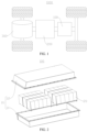
- FIG. 1 is a schematic structural diagram of a vehicle 1000 provided by some embodiments of the present application.
- a battery 100 is disposed inside the vehicle 1000, and the battery 100 may be disposed at a bottom, head or tail of the vehicle 1000.
- the battery 100 may be used for supplying power to the vehicle 1000.
- the battery 100 may be used as an operation power supply of the vehicle 1000.
- the vehicle 1000 may further include a controller 200 and a motor 300.
- the controller 200 is used for controlling the battery 100 to supply power to the motor 300, for example, for a working power demand of the vehicle 1000 during startup, navigation and running.
- the battery 100 may be used not only as an operation power supply of the vehicle 1000, but also as a driving power supply of the vehicle 1000 to replace or partially replace fuel or natural gas to provide driving power for the vehicle 1000.
- FIG. 2 is an exploded view of a battery 100 provided by some embodiments of the present application; and FIG. 3 is a schematic structural diagram of the battery 100 shown in FIG. 2 .
- the battery 100 includes a box 10, a battery cell 20, and a treatment device 30, where the battery cell 20 and the treatment device 30 are accommodated in the box 10, and the treatment device 30 is used for treating exhaust gases discharged from the battery cell 20 into the box 10, so as to adjust a concentration of a preset gas in the exhaust gases to below a corresponding preset value, where the preset gas is one or a mixture of combustible gases.
- the box 10 is a component for storing the battery cell 20, the box 10 provides a storage space for the battery cell 20, and the box 10 may have various structures.
- the box 10 may include a first part 11 and a second part 12, and the first part 11 and the second part 12 are closed to each other to jointly confine the storage space for accommodating the battery cell 20.
- the first part 11 and the second part 12 may be in various shapes, such as cuboids or cylinders.
- the first part 11 may be of a hollow structure with an open side
- the second part 12 may also be of a hollow structure with an open side
- the open side of the second part 12 is closed to the open side of the first part 11 to form the box 10 with the storage space.
- the first part 11 is of a hollow structure with an open side
- the second part 12 is of a plate-like structure
- the second part 12 is closed to the open side of the first part 11 to form the box 10 with the storage space.
- the first part 11 and the second part 12 may be sealed by a sealing element, which may be a sealing ring, a sealant, or the like.
- the battery cell 20 may be an energy storage unit that undergoes electrochemical reactions through an electrode assembly and an electrolytic solution to output electrical energy.
- the plurality of battery cells 20 may be in series connection, parallel connection, or series-parallel connection.
- the series-parallel connection refers to a combination of series connection and parallel connection in the plurality of battery cells 20.
- the plurality of battery cells 20 may first be connected in series, in parallel, or in series and parallel to form a battery module, and then a plurality of battery modules may be connected in series, in parallel, or in series and parallel to form a whole accommodated in the box 10.
- all the battery cells 20 may be directly connected in series, in parallel, or in series and parallel together, and then the whole formed by all the battery cells 20 is accommodated in the box 10.
- the battery 100 may further include a current collecting component 40, and the plurality of battery cells 20 may be electrically connected through the current collecting component 40 to implement the parallel, series, or series-parallel connection of the plurality of battery cells 20.
- the current collecting component 40 may be a metal conductor, such as copper, iron, aluminum, stainless steel, or aluminum alloy.
- the treatment device 30 is a component used for reducing concentrations of preset gases in the exhaust gases.
- the treatment device 30 may treat the exhaust gases in various ways to reduce the concentrations of the preset gases.
- the treatment device 30 provides a treatment medium to reduce the concentrations of the preset gases.
- the treatment medium may be a solid medium, a liquid medium, or a gas medium.
- the treatment medium may be at least one of a phase change material, an oxidant, a mixture of an oxidant and a catalyst, ultra-pure water, fluorinated liquid, or water-cooled liquid.
- the oxidant may be at least one of copper oxide, sodium peroxide, potassium permanganate, or the like, and the catalyst may be at least one of precious metal catalysts, such as palladium, platinum, or rhodium.
- the treatment medium is a solid phase change material and the temperature inside the box 10 increases due to thermal runaway of the battery cell 20, the phase change material changes from a solid state to a non-combustible liquid or gas medium to reduce the concentration of the preset gas.
- the treatment medium is an oxidant, which chemically reacts with the preset gas to reduce the concentration of the preset gas.
- the exhaust gases refer to gases discharged from the inside of the battery cell 20 when the battery cell 20 undergoes thermal runaway.
- the exhaust gases include combustible gases and non-combustible gases; the combustible gases include at least one of H 2 , CO, alkanes, electrolyte vapor, and the like; and the non-combustible gases include at least one of CO 2 , N 2 , and the like.
- the alkanes include at least one of CH 4 , C 2 H 4 , and C 3 H 8 .
- the preset gas is one or a mixture of combustible gases in the exhaust gases.
- the combustible gases in the exhaust gases are H 2 , CO, alkanes, and electrolyte vapor.
- the treatment device 30 may adjust the concentration of any combustible gas among the H 2 , CO, alkanes, and electrolyte vapor to a corresponding preset value, for example, adjust the concentration of hydrogen to be 4% or less to greatly reduce the risk of combustion after the combustible gas is discharged, or adjust the concentration of mixed combustible gases among the H 2 , CO, alkanes, and electrolyte vapor to a corresponding preset value to reduce a probability of fire in the battery.
- the preset value may be a lower limit of combustion of the preset gas, and a minimum concentration that can propagate flame is called the lower limit of combustion of the preset gas.
- the preset gas is electrolyte vapor, and the treatment device 30 can reduce the concentration of the electrolyte vapor to below the lower limit of combustion.
- the preset gas is a mixed gas of H 2 , CO, and alkanes, and the treatment device 30 can reduce the concentration of the mixed gas of H 2 , CO, and alkanes to below the lower limit of combustion.
- the treatment device 30 is disposed inside the box 10, and the treatment device 30 can treat the exhaust gases discharged into the box 10 when the battery cell 20 undergoes thermal runaway, thereby reducing the concentration of one or a mixture of combustible gases in the exhaust gases to below the preset value, reducing flammability levels of the combustible gases, reducing risks of combustion and explosion of the battery 100, and effectively improving the safety of the battery cell 20.
- the preset gas is electrolyte vapor, and the preset value is 3.6%.
- the treatment device 30 can treat the electrolyte vapor in the exhaust gases to reduce the concentration of the electrolyte vapor. For example, the treatment device 30 reduces the concentration of the electrolyte vapor in the exhaust gases to 1.2% to 3.6%.
- the treatment device 30 adjusts the concentration of the electrolyte vapor to below 3.6% (including 3.6%), so that the concentration of the electrolyte vapor is below the lower limit of combustion, the risk of combustion of the electrolyte vapor is reduced, and the safety of the battery cell 20 is improved.
- the preset gas is a mixed combustible gas of H 2 , CO, and alkanes, and the preset value is 7.6%.
- the treatment device 30 can treat the mixed combustible gas of H 2 , CO, and alkanes in the exhaust gases to reduce the concentration of the mixed combustible gas of H 2 , CO, and alkanes. For example, the treatment device 30 reduces the concentration of the mixed combustible gas of H 2 , CO, and alkanes in the exhaust gases to 4.4% to 7.6%.
- the treatment device 30 adjusts the concentration of the mixed combustible gas of H 2 , CO, and alkanes to below 7.6% (including 7.6%), so that the concentration of the mixed combustible gas of H 2 , CO, and alkanes is below the lower limit of combustion, the risk of combustion of the mixed combustible gas of H 2 , CO, and alkanes is reduced, and the safety of the battery cell 20 is improved.
- the preset gas includes all combustible gases in the exhaust gases, and the preset value is 8.3%.
- the combustible gases in the exhaust gases are H 2 , CO, alkanes, and electrolyte vapor
- the treatment device 30 can treat the mixed combustible gases of H 2 , CO, alkanes, and electrolyte vapor to reduce the concentration of the mixed combustible gases of H 2 , CO, alkanes, and electrolyte vapor.
- the treatment device 30 reduces the concentration of all the mixed combustible gases in the exhaust gases to 2% to 8.3%.
- the treatment device 30 adjusts the concentration of all the mixed combustible gases in the exhaust gases to below 8.3% (including 8.3%) to reduce the risk of combustion of the exhaust gases and improve the safety of the battery cell 20.
- FIG. 4 is a control schematic diagram of the treatment device 30 provided by the embodiments of the present application.
- the battery 100 further includes a detection unit 50 and a control unit 60.
- the detection unit 50 is disposed inside the box 10, and the detection unit 50 is used for detecting the concentration of the preset gas.
- the control unit 60 is electrically connected to the detection unit 50 and the treatment device 30, and the control unit 60 is used for controlling the treatment device 30 to release the treatment medium when the concentration of the preset gas in the exhaust gases is higher than the corresponding preset value.
- the detection unit 50 is a component that detects the concentration of the preset gas.
- the detection unit 50 may be a device with a concentration sensor, or a device with a photoelectric sensor, such as a Raman analyzer.
- the detection unit 50 is used for detecting the concentration of the preset gas.
- the detection unit 50 can detect the concentration of each combustible gas and obtain the concentration of the mixture of combustible gases by calculation and analysis.
- the detection unit 50 is used for controlling the operation of the treatment device 30 according to the detection results of the detection unit 50, so that the treatment device 30 releases the treatment medium when the concentration of the preset gas is higher than the corresponding preset value, to reduce the concentration of the preset gas.
- the preset gas includes all combustible gases in the exhaust gases and the preset value is 8.3%.
- the control unit 60 will control the treatment device 30 to release the treatment medium.
- the control unit 60 may be disposed inside the box 10 or outside the box 10.
- the control unit 60 may be a single chip microcomputer or a PLC (Programmable Logic Controller).
- the control unit 60 controls the treatment device 30 to release the treatment system, so as to adjust the concentration of the preset gas to below the corresponding preset value and achieve automatic control on the treatment device 30.
- the treatment device 30 may include a receiving component 31 and a switching unit 32.
- An accommodating space 311 is formed inside the receiving component 31, and the accommodating space 311 is used for accommodating the treatment medium.
- the switching unit 32 is electrically connected to the control unit 60, and the control unit 60 is used for controlling the switching unit 32 to open when the concentration of the preset gas in the exhaust gases is higher than the corresponding preset value to release the treatment medium.
- the receiving component 31 is a component that provides the treatment medium, the accommodating space 311 is formed therein, and the treatment medium is accommodated in the accommodating space 311.
- the receiving component 31 may be placed inside the box 10 or fixed inside the box 10.
- the switching unit 32 is a component that connects or disconnects the inside of the box 10 and the accommodating space 311.
- the control unit 60 can control the switching unit 32 to open or close. When the switching unit 32 is opened, the inside of the box 10 is connected to the accommodating space 311. When the switching unit 32 is closed, the inside of the box 10 is disconnected from the accommodating space 311.
- the switching unit 32 may be an electronically controlled switching valve.
- control unit 60 controls the switching unit 32 to open to release the treatment medium accommodated in the receiving component 31, so as to treat the exhaust gases inside the box 10.
- the overall structure of the treatment device 30 is simple.
- the battery 100 further includes a pressure relief mechanism 70, the pressure relief mechanism 70 is disposed on the box 10, and the pressure relief mechanism 70 is electrically connected to the control unit 60.
- the control unit 60 is used for controlling the pressure relief mechanism 70 to actuate when the concentration of the preset gas in the exhaust gases is lower than the corresponding preset value, so as to release the pressure inside the box 10.
- the pressure relief mechanism 70 disposed on the box 10 can be automatically controlled by the control unit 60.
- the pressure relief mechanism 70 is a component used for releasing pressure inside the battery cell 20.
- the pressure relief mechanism 70 can be actuated under the control of the control unit 60, so that the exhaust gases inside the box 10 can be discharged to the outside of the box 10 through the pressure relief mechanism 70, to achieve the purpose of releasing the pressure inside the battery cell 20.
- the pressure relief mechanism 70 may be in a form of an explosion-proof valve, explosion-proof disc, air valve, pressure relief valve, or switching valve.
- the "actuated" mentioned in the present application indicates that the pressure relief mechanism 70 acts or is activated to a certain state, so that the internal pressure and temperature of the battery cell 20 are released.
- the action generated by the pressure relief mechanism 70 may include, but is not limited to: at least a portion of the pressure relief mechanism 70 is fractured, broken, torn, and the like.
- the pressure relief mechanism 70 is a switching valve, and the control unit 60 can control the pressure relief mechanism 70 to open or close, so as to connect or disconnect the inside and outside of the box 10.
- control unit 60 controls the pressure relief mechanism 70 to actuate, the control unit 60 can control the pressure relief mechanism 70 to be in a closed state, and the treatment device 30 will not release the treatment medium into the box 10 any more.
- the control unit 60 will control the pressure relief mechanism 70 to actuate, thereby discharging the exhaust gases that meet discharge requirements inside the box 10 to the outside of the box 10, to reduce the pressure inside the box 10.
- the concentration of the preset gas discharged to the outside of the box 10 is below the preset value, the preset gas is unlikely to burn, which ensures the safety of the battery 100.
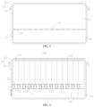
- FIG. 5 is a schematic structural diagram of the box 10 shown in FIG. 4 .
- the battery 100 further includes a pressure relief mechanism 70, and the pressure relief mechanism 70 is used for releasing the pressure inside the box 10 after actuated.
- the box 10 includes a first space 13 and a second space 14 that are separated, the first space 13 is used for accommodating the battery cell 20, the second space 14 is used for accommodating the exhaust gases, and the pressure relief mechanism 70 is configured to connect the exterior of the box 10 and the second space 14 after actuated.
- the detection unit 50 and the control unit 60 may be disposed in the battery 100, or the detection unit 50 and the control unit 60 may not be disposed. If the detection unit 50 and the control unit 60 are disposed in the battery 100, the pressure relief mechanism 70 is actively actuated. If the detection unit 50 and the control unit 60 are not disposed in the battery 100, the pressure relief mechanism 70 is passively actuated. For example, when the internal pressure of the box 10 reaches a threshold, the pressure relief mechanism 70 is passively actuated to release the internal pressure of the box 10.
- the arrangement direction of the first space 13 and the second space 14 may be the same as that of the first part 11 and the second part 12, or the arrangement direction of the first space 13 and the second space 14 may be perpendicular to that of the first part 11 and the second part 12.
- the arrangement direction of the first space 13 and the second space 14 may be the same as that of the first part 11 and the second part 12.
- the volume of the first space 13 is greater than that of the second space 14.
- the first space 13 and the second space 14 separated from each other in the box 10 are used for accommodating the battery cell 20 and discharging the exhaust gases respectively, so that the battery cell 20 and the exhaust gases are separated from each other to reduce the impact of the exhaust gases on the battery cell 20 and further improve the safety.
- the pressure relief portion 21 is a component used for releasing the pressure inside the battery cell 20. When the battery cell 20 undergoes thermal runaway, the battery cell 20 will discharge exhaust gases outward through the pressure relief portion 21.
- the pressure relief portion 21 may be a weak area on a shell of the battery cell 20, or a pressure relief element disposed on the shell.
- the pressure relief element may be in a form of an explosion-proof valve, explosion-proof disc, air valve, pressure relief valve, or switching valve.
- the shell is a component of the battery cell 20 for accommodating the electrode assembly.
- the pressure relief portion 21 of the battery cell 20 faces the second space 14, so that the exhaust gases discharged when the battery cell 20 undergoes thermal runaway can enter the second space 14 more easily.
- the first space 13 and the second space 14 are separated by a separating member 15, the separating member 15 is provided with a channel 151, and the channel 151 connects the first space 13 and the second space 14.
- the separating member 15 is a member that separates the first space 13 and the second space 14.
- the separating member 15 may be of a flat plate structure fixed inside the box 10.
- the box 10 includes a first part 11 and a second part 12
- the first part 11 may be disposed at a bottom of the second part 12
- the separating member 15 may be fixed inside the first part 11, and the pressure relief mechanism 70 may be disposed at the first part 11.
- the channel 151 may correspond to the battery cell 20 one to one.
- the channel 151 may extend linearly or non-linearly, for example, the channel 151 extends along a bend line.
- the channel 151 is a linear channel 151 extending along a thickness of the separating member 15, and the channel 151 runs through two surfaces of the separating member 15 along the thickness, so as to connect the first space 13 and the second space 14.
- the separating member 15 is used for supporting the battery cell 20, and the separating member 15 is configured as a thermal management component for managing the temperature of the battery cell 20.
- the first space 13 and the second space 14 are in a connected state, and the exhaust gases discharged when the battery cell 20 undergoes thermal runaway can enter the second space 14 through the channel 151.
- the battery cell 20 has a pressure relief portion 21, and the pressure relief portion 21 is located at one end of the channel 151 in a run-through direction Y and faces the channel 151.
- the channel 151 is a linear channel 151 extending along the thickness of the separating member 15, and the run-through direction Y of the channel 151 is an extension direction of the channel 151, which may also be understood as the thickness direction of the separating member 15.
- the pressure relief portion 21 is disposed at one end of the channel 151 in the run-through direction Y and faces the channel 151, and the exhaust gases discharged when the battery cell 20 undergoes thermal runaway can directly enter the channel 151, so that the exhaust gases enter the second space 14 faster.
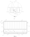
- FIG. 6 is a schematic structural diagram of a battery 100 provided by other embodiments of the present application
- FIG. 7 is a partially enlarged view of part A of the battery 100 shown in FIG. 6
- the treatment device 30 includes the separating member 15, the separating member 15 is provided with an inner cavity 152, the inner cavity 152 is used for accommodating the treatment medium, a side wall of the channel 151 is provided with a switching portion 153, and the switching portion 153 is configured to allow the treatment medium in the inner cavity 152 to flow out via the switching portion 153 when opened.
- the separating member 15 may be used as a portion of the treatment device 30.
- the separating member 15 serves as a separating component for separating the first space 13 and the second space 14, and as a treatment component for providing the treatment medium.
- the inner cavity 152 is an internal space of the separating member 15, and is used for accommodating the treatment medium. There may be one or more inner cavities 152 inside the separating member 15.
- the inner cavity 152 and the channel 151 correspond one to one, that is, the treatment medium in one inner cavity 152 correspondingly flows into one channel 151.
- One inner cavity 152 may alternatively correspond to a plurality of channels 151, that is, the treatment medium in one inner cavity 152 correspondingly flows into the plurality of channels 151.
- the switching portion 153 is a component used for connecting or disconnecting the inner cavity 152 and the channel 151. After the switching portion 153 is opened, the treatment medium in the inner cavity 152 flows out into the channel 151 via the switching portion 153.
- control unit 60 may be electrically connected to the switching portion 153, and the control unit 60 controls the switching portion 153 to open or close.
- the treatment medium in the inner cavity 152 can be released via the switching portion 153, so as to reduce the concentration of the preset gas in the exhaust gases faster.
- the switching portion 153 is a nozzle, and a spraying direction X of the nozzle intersects with the run-through direction Y of the channel 151.
- the spraying direction X of the nozzle and the run-through direction Y of the channel 151 are not parallel to each other, and the two may be at an angle.
- the run-through direction Y of the channel 151 is the same as a flow direction of the exhaust gases discharged by the battery cell 20 in the channel 151.
- the spraying direction X of the nozzle is perpendicular to the run-through direction Y of the channel 151.
- the nozzle is equipped with a switching valve, and the control unit 60 controls the switching valve to open or close the nozzle, so that the treatment medium in the inner cavity 152 can be sprayed out through the nozzle.
- the spraying direction X of the nozzle intersects with the run-through direction Y of the channel 151, so that the treatment medium sprayed out from the nozzle can be more fully mixed with the exhaust gases, the treatment effect on the exhaust gases is better, and the concentration of the preset gas in the exhaust gases can be reduced faster.
- the spraying direction X of the nozzle is perpendicular to the run-through direction Y of the channel 151, the treatment effect of the treatment medium sprayed by the nozzle on the exhaust gases can be further improved.
- the switching portion 153 may alternatively be of other structures, for example, the separating member 15 is provided with a first connecting channel connecting the inner cavity 152 and the channel 151, the switching portion 153 closes the first connecting channel, and the switching portion 153 is of a thermo-sensitive material. When the temperature reaches a melting point of the switching portion 153, the switching portion 153 partially or completely melts, thereby opening the first connecting channel to connect the inner cavity 152 and the channel 151.
- FIG. 8 is a schematic structural diagram of a battery 100 provided by still other embodiments of the present application.
- the first space 13 and the second space 14 are separated by the separating member 15, the separating member 15 is provided with a switching mechanism 154, and the switching mechanism 154 is configured to connect or disconnect the first space 13 and the second space 14.
- the switching mechanism 154 is a component that connects or disconnects the first space 13 and the second space 14. After the switching mechanism 154 is opened, the first space 13 and the second space 14 are in a connected state, and the exhaust gases discharged from the battery cell 20 into the first space 13 may enter the second space 14 through the switching mechanism 154.
- switching mechanisms 154 there may be one or more switching mechanisms 154 on the separating member 15.
- the separating member 15 is provided with a plurality of switching mechanisms 154, and the switching mechanisms 154 correspond to the battery cells 20 one to one.
- the switching mechanism 154 disposed on the separating member 15 can connect or disconnect the first space 13 and the second space 14.
- the switching mechanism 154 may be in a closed state, so that the first space 13 and the second space 14 are independent of each other.
- the switching mechanism 154 may be in an open state, so that the first space 13 and the second space 14 are connected to each other, and the exhaust gases can enter the second space 14 from the first space 13.
- the switching mechanism 154 is a weak portion, and the weak portion is configured to connect the first space 13 and the second space 14 after being damaged by the exhaust gases.
- the weak portion is a thinner portion on the separating member 15 than other areas.
- the weak portion may connect the first space 13 and the second space 14 by means of rupture, detachment, melting, or the like under the action of the exhaust gases.
- the switching mechanism 154 can be passively opened under the action of the exhaust gases, with a simple structure and good economic efficiency.
- the switching mechanism 154 may alternatively be of other structures, for example, the switching mechanism 154 is a switching valve disposed on the separating member 15.
- the switching mechanism 154 may be electrically connected to the control unit 60, and the switching mechanism 154 may be opened or closed through the control unit 60.
- the treatment device 30 is disposed in the second space 14.
- the control unit 60, the detection unit 50, the receiving component 31, and the switching unit 32 may all be disposed in the second space 14.
- the treatment device 30 is disposed in the second space 14. After the exhaust gases enter the second space 14, the treatment device 30 can treat the exhaust gases in the second space 14, so as to reduce the concentration of the preset gas in the exhaust gases.
- FIG. 9 is a schematic structural diagram of a battery 100 provided by further embodiments of the present application.
- the battery cell 20 has a pressure relief portion 21.
- the treatment device 30 includes a support member 33, the support member 33 is used for supporting the battery cell 20, an avoidance cavity 331 is disposed on a side, facing the battery cell 20, of the support member 33, the avoidance cavity 331 is used for avoiding the pressure relief portion 21, and the avoidance cavity 331 accommodates the treatment medium.
- the support member 33 may be of a plate-like structure, and the avoidance cavity 331 may be a groove disposed on a surface, facing the battery cell 20, of the support member 33.
- the plurality of battery cells 20 may share one avoidance cavity 331, or one battery cell 20 may be correspondingly provided with one avoidance cavity 331.
- the plurality of battery cells 20 share one avoidance cavity 331.
- the treatment medium accommodated in the avoidance cavity 331 may be a solid phase change material, an oxidant, a mixture of an oxidant and a catalyst, or the like.
- the avoidance cavity 331 of the support member 33 for avoiding the pressure relief portion 21 of the battery cell 20 is filled with the treatment medium, and the exhaust gases discharged from the pressure relief portion 21 can directly flow to the treatment medium, whereby the concentration of the preset gas in the exhaust gases is quickly reduced through the treatment medium.
- FIG. 10 is an exploded view of a battery cell 20 and a support member 33 provided by some embodiments of the present application; and FIG. 11 is a schematic structural diagram of the support member 33 shown in FIG. 10 .
- the battery cell 20 has a pressure relief portion 21.
- the treatment device 30 includes a support member 33, the support member 33 is used for supporting the battery cell 20, an avoidance cavity 331 is disposed on a side, facing the battery cell 20, of the support member 33, the avoidance cavity 331 is used for avoiding the pressure relief portion 21, a trigger mechanism 332 is disposed in the avoidance cavity 331, an accommodating cavity is disposed inside the support member 33, the accommodating cavity is used for accommodating the treatment medium, and the trigger mechanism 332 is configured to allow the treatment medium in the accommodating cavity to be discharged via the trigger mechanism 332 after triggered.
- the trigger mechanism 332 may be triggered in various ways. For example, the trigger mechanism 332 is triggered by the exhaust gases discharged when the battery cell 20 undergoes thermal runaway. For another example, the trigger mechanism 332 is triggered by voltage or current of the battery cell 20. When the voltage or current of the battery cell 20 reaches a threshold, the trigger mechanism 332 is triggered.
- the exhaust gases inside the battery cell 20 will be discharged into the avoidance cavity 331 through the pressure relief portion 21. Because the trigger mechanism 332 is provided with the avoidance cavity 331, the treatment medium discharged via the trigger mechanism 332 can be fully mixed with the exhaust gases in the avoidance cavity 331 after the trigger mechanism 332 is triggered, thereby quickly reducing the concentration of the preset gas in the exhaust gases.
- the trigger mechanism 332 is configured to be triggered by the exhaust gases.
- the trigger mechanism 332 may be of various structures.
- the support member 33 serves as the receiving component 31
- the trigger mechanism 332 serves as the switching unit 32
- the control unit 60 controls the trigger mechanism 332
- the trigger mechanism 332 is triggered by detecting the concentration of the preset gas through the detection unit 50.
- the support member 33 is provided with a second connecting channel connecting the avoidance cavity 331 and the accommodating cavity
- the trigger mechanism 332 closes the second connecting channel
- the trigger mechanism 332 is of a thermo-sensitive material.
- the trigger mechanism 332 partially or completely melts, so that the treatment medium can be discharged into the avoidance cavity 331 by the trigger mechanism 332.
- the trigger mechanism 332 of the above structure is triggered by the exhaust gases.
- the trigger mechanism 332 In the normal working environment, the trigger mechanism 332 is not triggered, and the treatment medium accommodated in the accommodating cavity will not be discharged.
- the trigger mechanism 332 can be triggered by the exhaust gases discharged by the battery cell 20, so that the treatment medium is discharged in a timely manner to reduce the concentration of the preset gas in the exhaust gases.
- the support member 33 is configured as a thermal management component.
- the thermal management component is used for accommodating a fluid to regulate the temperature of the battery cell 20.
- the fluid may be ultra-pure water, fluorinated liquid, water-cooled liquid, or the like.
- the thermal management component may be a cooling component that cools the battery cell 20, or a heating component that heats the battery cell 20.
- a flow channel in which the fluid flows is disposed inside the thermal management component. In an embodiment where an accommodating cavity for accommodating a treatment medium is disposed inside the support member 33, the flow channel and the accommodating cavity are independent from and not connected to each other.
- the support member 33 has abilities to manage the temperature of the battery cell 20 and reduce the concentration of the preset gas in the exhaust gases.
- An embodiment of the present application further provides an electrical device, including the battery 100 provided by any of the foregoing embodiments. It should be noted that the embodiments in the present application and the features in the embodiments may be combined with each other on a non-conflict basis.
Landscapes
- Chemical & Material Sciences (AREA)
- Chemical Kinetics & Catalysis (AREA)
- Electrochemistry (AREA)
- General Chemical & Material Sciences (AREA)
- Engineering & Computer Science (AREA)
- Manufacturing & Machinery (AREA)
- Microelectronics & Electronic Packaging (AREA)
- Automation & Control Theory (AREA)
- Gas Exhaust Devices For Batteries (AREA)
- Battery Mounting, Suspending (AREA)
Abstract
Description
- The present application relates to the field of battery technologies, and in particular, to a battery and an electrical device.
- With the development of new energy technologies, batteries are increasingly widely used, such as in mobile phones, notebook computers, scooters, electric vehicles, electric airplanes, electric ships, electric toy cars, electric toy ships, electric toy planes, and electric tools.
- In battery technologies, performance and safety of batteries are required to be considered. Therefore, how to improve the safety of batteries is an urgent problem to be solved in the battery technologies.
- Embodiments of the present application provide a battery and an electrical device to effectively improve the safety of the battery.
- In a first aspect, an embodiment of the present application provides a battery, including a box body, and a battery cell and a treatment device accommodated in the box, where the treatment device is used for treating exhaust gases discharged from the battery cell into the box, so as to adjust a concentration of a preset gas in the exhaust gases to below a corresponding preset value, where the preset gas is one or a mixture of combustible gases.
- In the foregoing technical solution, the treatment device is disposed inside the box, and the treatment device can treat the exhaust gases discharged into the box when the battery cell undergoes thermal runaway, thereby reducing the concentration of one or a mixture of combustible gases in the exhaust gases to below the preset value, reducing flammability levels of the combustible gases, reducing risks of combustion and explosion of the battery, and effectively improving the safety of the battery.
- In some embodiments, the preset gas is electrolyte vapor, and the preset value is 3.6%. The treatment device adjusts the concentration of the electrolyte vapor to below 3.6%, so that the concentration of the electrolyte vapor is below a lower limit of combustion, the risk of combustion of the electrolyte vapor is reduced, and the safety of the battery is improved.
- In some embodiments, the preset gas is a mixed combustible gas of H2, CO, and alkanes, and the preset value is 7.6%. The treatment device adjusts the concentration of the mixed combustible gas of H2, CO, and alkanes to below 7.6%, so that the concentration of the mixed combustible gas of H2, CO, and alkanes is below the lower limit of combustion, the risk of combustion of the mixed combustible gas of H2, CO, and alkanes is reduced, and the safety of the battery is improved.
- In some embodiments, the preset gas includes all combustible gases in the exhaust gases, and the preset value is 8.3%. The treatment device adjusts the concentration of all the mixed combustible gases in the exhaust gases to below 8.3% to reduce the risk of combustion of the exhaust gases and improve the safety of the battery.
- In some embodiments, the battery further includes a detection unit and a control unit; the detection unit is disposed inside the box, and the detection unit is used for detecting the concentration of the preset gas; and the control unit is electrically connected to the detection unit and the treatment device, and the control unit is used for controlling the treatment device to release a treatment medium when the concentration of the preset gas in the exhaust gases is higher than the corresponding preset value. When the detection unit detects that the preset gas is higher than the corresponding preset value, the control unit controls the treatment device to release the treatment medium, so as to adjust the concentration of the preset gas to below the corresponding preset value and achieve automatic control on the treatment device.
- In some embodiments, the treatment device includes a receiving component and a switching unit; an accommodating space is formed in the receiving component, and the accommodating space is used for accommodating the treatment medium; and the switching unit is electrically connected to the control unit, and the control unit is used for controlling the switching unit to open when the concentration of the preset gas is higher than the corresponding preset value to release the treatment medium. The control unit controls the switching unit to open to release the treatment medium accommodated in the receiving component, so as to treat the exhaust gases inside the box. The overall structure of the treatment device is simple.
- In some embodiments, the battery further includes a pressure relief mechanism disposed on the box, where the pressure relief mechanism is electrically connected to the control unit; and the control unit is used for controlling the pressure relief mechanism to actuate when the concentration of the preset gas is lower than the corresponding preset value, so as to release pressure inside the box. The pressure relief mechanism disposed on the box can be automatically controlled by the control unit. When the treatment device releases the treatment medium to adjust the concentration of the preset gas to below the corresponding preset value, the control unit will control the pressure relief mechanism to actuate, thereby discharging the exhaust gases that meet discharge requirements inside the box to the outside of the box, to reduce the pressure inside the box.
- In some embodiments, the battery further includes a pressure relief mechanism, and the pressure relief mechanism is used for releasing pressure inside the box after actuated; and the box includes a first space and a second space that are separated, the first space is used for accommodating the battery cell, the second space is used for accommodating the exhaust gases, and the pressure relief mechanism is configured to connect the outside of the box and the second space after actuated. The first space and the second space separated from each other in the box are used for accommodating the battery cell and discharging the exhaust gases respectively, so that the battery cell and the exhaust gases are separated from each other to reduce the impact of the exhaust gases on the battery cell and further improve the safety.
- In some embodiments, the battery cell has a pressure relief portion, and the pressure relief portion is provided facing the second space. In this case, the exhaust gases discharged when the battery cell undergoes thermal runaway can enter the second space more easily.
- In some embodiments, the first space and the second space are separated by a separating member, the separating member is provided with a channel, and the channel connects the first space and the second space. In this case, the first space and the second space are in a connected state, and the exhaust gases discharged when the battery cell undergoes thermal runaway can enter the second space through the channel.
- In some embodiments, the battery cell has a pressure relief portion, and the pressure relief portion is located at one end of the channel in a run-through direction and faces the channel. In this case, the exhaust gases discharged when the battery cell undergoes thermal runaway can directly enter the channel, so that the exhaust gases enter the second space faster.
- In some embodiments, the treatment device includes the separating member, the separating member is provided with an inner cavity, the inner cavity is used for accommodating the treatment medium, a side wall of the channel is provided with a switching portion, and the switching portion is configured to allow the treatment medium in the inner cavity to flow out via the switching portion when opened. The separating member serves as a separating component for separating the first space and the second space, and as a treatment component for providing the treatment medium. When the exhaust gases enter the second space via the channel, the treatment medium in the inner cavity can be released via the switching portion, so as to reduce the concentration of the preset gas in the exhaust gases faster.
- In some embodiments, the switching portion is a nozzle, and a spraying direction of the nozzle intersects with the run-through direction of the channel. In this case, the treatment medium sprayed out from the nozzle can be more fully mixed with the exhaust gases, the treatment effect on the exhaust gases is better, and the concentration of the preset gas in the exhaust gases can be reduced faster.
- In some embodiments, the first space and the second space are separated by the separating member, the separating member is provided with a switching mechanism, and the switching mechanism is configured to connect or disconnect the first space and the second space. The switching mechanism disposed on the separating member can connect or disconnect the first space and the second space. In a normal working environment, the switching mechanism may be in a closed state, so that the first space and the second space are independent of each other. When the battery cell undergoes thermal runaway, the switching mechanism may be in an open state, so that the first space and the second space are connected to each other, and the exhaust gases can enter the second space from the first space.
- In some embodiments, the switching mechanism is a weak portion, and the weak portion is configured to connect the first space and the second space after being damaged by the exhaust gases. The switching mechanism with this structure can be passively opened under the action of the exhaust gases, with a simple structure and good economic efficiency.
- In some embodiments, the treatment device is disposed in the second space. After the exhaust gases enter the second space, the treatment device can treat the exhaust gases in the second space, so as to reduce the concentration of the preset gas in the exhaust gases.
- In some embodiments, the battery cell has a pressure relief portion; and the treatment device includes a support member, the support member is used for supporting the battery cell, an avoidance cavity is disposed on a side, facing the battery cell, of the support member, the avoidance cavity is used for avoiding the pressure relief portion, and the avoidance cavity accommodates the treatment medium. In this case, the exhaust gases discharged from the pressure relief portion can directly flow to the treatment medium, whereby the concentration of the preset gas in the exhaust gases is quickly reduced through the treatment medium.
- In some embodiments, the battery cell has a pressure relief portion; the treatment device includes a support member, the support member is used for supporting the battery cell, an avoidance cavity is disposed on a side, facing the battery cell, of the support member, and the avoidance cavity is used for avoiding the pressure relief portion; and a trigger mechanism is disposed in the avoidance cavity, an accommodating cavity is disposed inside the support member, the accommodating cavity is used for accommodating the treatment medium, and the trigger mechanism is configured to allow the treatment medium in the accommodating cavity to be discharged via the trigger mechanism after triggered. When the battery cell undergoes thermal runaway, the exhaust gases inside the battery cell will be discharged into the avoidance cavity through the pressure relief portion. Because the trigger mechanism is provided with the avoidance cavity, the treatment medium discharged via the trigger mechanism can be fully mixed with the exhaust gases in the avoidance cavity after the trigger mechanism is triggered, thereby quickly reducing the concentration of the preset gas in the exhaust gases.
- In some embodiments, the trigger mechanism is configured to be triggered by the exhaust gases. In the normal working environment, the trigger mechanism is not triggered, and the treatment medium accommodated in the accommodating cavity will not be discharged. When the battery cell undergoes thermal runaway, the trigger mechanism can be triggered by the exhaust gases discharged by the battery cell, so that the treatment medium is discharged in a timely manner to reduce the concentration of the preset gas in the exhaust gases.
- In some embodiments, the support member is configured as a thermal management component. The support member has abilities to manage the temperature of the battery cell and reduce the concentration of the preset gas in the exhaust gases.
- In a second aspect, an embodiment of the present application further provides an electrical device, including at least one battery provided by any of the embodiments of the first aspect.
- In order to explain the technical solutions in the embodiments of the present application more clearly, accompanying drawings required to use in the embodiments will be simply introduced below. It should be understood that the following drawings show only some embodiments of the present application and should not be regarded as limiting the scope, and other relevant drawings may be obtained based on these drawings by those of ordinary skill in the art without any creative efforts.
-
FIG. 1 is a schematic structural diagram of a vehicle provided by some embodiments of the present application; -
FIG. 2 is an exploded view of a battery provided by some embodiments of the present application; -
FIG. 3 is a schematic structural diagram of a battery shown inFIG. 2 ; -
FIG. 4 is a control schematic diagram of a treatment device provided by an embodiment of the present application; -
FIG. 5 is a schematic structural diagram of a box shown inFIG. 4 ; -
FIG. 6 is a schematic structural diagram of a battery provided by other embodiments of the present application; -
FIG. 7 is a partially enlarged view of part A of the battery shown inFIG. 6 ; -
FIG. 8 is a schematic structural diagram of a battery provided by still other embodiments of the present application; -
FIG. 9 is a schematic structural diagram of a battery provided by further embodiments of the present application; -
FIG. 10 is an exploded view of a battery cell and a support member provided by some embodiments of the present application; and -
FIG. 11 is a schematic structural diagram of the support member shown inFIG. 10 . - Reference numerals: 10 - box; 11 - first part; 12 - second part; 13 - first space; 14 - second space; 15 - separating member; 151 - channel; 152 - inner cavity; 153 - switching portion; 154 - switching mechanism; 20 - battery cell; 21 - pressure relief portion; 30 - treatment device; 31 - receiving component; 311 - accommodating space; 32 - switching unit; 33 - support member; 331 - avoidance cavity; 332 - trigger mechanism; 40 - current collecting component; 50 - detection unit; 60 - control unit; 70 - pressure relief mechanism; 100 - battery; 200 - controller; 300 - motor; 1000 - vehicle; X - spraying direction; Y - run-through direction.
- To make the objectives, technical solutions and advantages of the embodiments of the present application clearer, the technical solutions in the embodiments of the present application will be described clearly below with reference to the accompanying drawings in the embodiments of the present application. Apparently, the described embodiments are some but not all of the embodiments of the present application. All other embodiments obtained by those of ordinary skill in the art based on the embodiments of the present application without creative efforts shall fall within the protection scope of the present application.
- Unless otherwise defined, all technical and scientific terms used in the present application have the same meanings as those commonly understood by technical personnel in the technical field of the present application; the terms used in the specification of the present application are only for the purpose of describing specific embodiments and are not intended to limit the present application; and the terms "include" and "have" in the specification and claims of the present application, the accompanying drawings, and any variations thereof, are intended to cover non-exclusive inclusion. The terms "first", "second", and the like in the specification and claims of the present application or the accompanying drawings are used to distinguish different objects, rather than to describe specific sequences or primary and secondary relationships.
- The "embodiment" mentioned in the present application means that specific features, structures or characteristics described in conjunction with the embodiment may be included in at least one embodiment of the present application. The phrase at various locations in the specification does not necessarily refer to the same embodiment, or an independent or alternative embodiment exclusive of another embodiment.
- In the description of the present application, it should be noted that, unless otherwise specified and defined, the terms "mounted", "connected", "connection", and "attached" should be broadly understood, for example, the "connection" may be a fixed connection, a detachable connection, an integral connection, a direct connection, a connection through a medium, or an internal communication between two elements. Those of ordinary skill in the art may understand the specific meanings of the above terms in the present application according to specific circumstances.
- The term "and/or" in the present application is merely an association relationship for describing associated objects, and represents that three relationships may exist. For example, A and/or B may represent the following three cases: A exists alone, both A and B exist, and B exists alone. In addition, the character "/" in the present application generally indicates an "or" relationship between the associated objects.
- In the embodiments of the present application, the same reference numerals represent the same components, and for simplicity, detailed descriptions of the same components are omitted in different embodiments. It should be understood that, in the embodiments of the present application shown in the accompanying drawings, dimensions of various components and integrated apparatuses, such as thickness, length, and width, are only illustrative and should not constitute any limitations on the present application.
- In the present application, "a plurality of" means two (inclusive) or more.
- In the present application, battery cells may include lithium-ion secondary batteries, lithium-ion primary batteries, lithium-sulfur batteries, sodium lithium-ion batteries, sodium-ion batteries, magnesium-ion batteries, or the like, which are not limited by the embodiments of the present application. The battery cells may be cylindrical, flat, cuboid, or in other shapes, which is also not limited by the embodiments of the present application. The battery cells are generally divided into three types according to ways of packaging: cylindrical battery cells, square battery cells and soft package battery cells, which are also not limited in the embodiments of the present application.
- The battery mentioned in the embodiments of the present application refers to a single physical module that includes one or more battery cells to provide higher voltage and capacity. For example, the battery mentioned in the present application may include a battery module or a battery pack. The battery generally includes a box used for packaging one or more battery cells. The box may prevent liquid or other foreign matters from affecting charging or discharging of the battery cells.
- The battery cell includes an electrode assembly and an electrolytic solution, where the electrode assembly includes a positive electrode plate, a negative electrode plate, and a separator. The battery cell mainly relies on migration of metal ions between the positive electrode plate and the negative electrode plate to work. The positive electrode plate includes a positive electrode current collector and a positive electrode active material layer, a surface of the positive electrode current collector is coated with the positive electrode active material layer, and the positive electrode current collector not coated with the positive electrode active material layer protrudes from the positive electrode current collector coated with the positive electrode active material layer and is used as a positive electrode tab. In an example of a lithium-ion battery, a material of the positive electrode current collector may be aluminum, and a positive electrode active material may be lithium cobaltate, lithium iron phosphate, ternary lithium, lithium manganate, or the like. The negative electrode plate includes a negative electrode current collector and a negative electrode active material layer, a surface of the negative electrode current collector is coated with the negative electrode active material layer, and the negative electrode current collector not coated with the negative electrode active material layer protrudes from the negative electrode current collector coated with the negative electrode active material layer and is used as a negative electrode tab. A material of the negative electrode current collector may be copper, and a negative electrode active material may be carbon, silicon, or the like. In order to ensure that no fusing occurs when high current passes through, there is a plurality of positive electrode tabs laminated together, and there is a plurality of negative electrode tabs laminated together. A material of the separator may be polypropylene (PP), polyethylene (PE), or the like. Moreover, the electrode assembly may be of a wound structure or a laminated structure, and the embodiments of the present application are not limited thereto.
- The development of battery technology needs to consider various design factors simultaneously, such as energy density, cycle life, discharge capacity, charge and discharge rate, and other performance parameters. In addition, safety of batteries should also be considered.
- To improve the safety of the battery, a pressure relief mechanism is usually disposed on the box. When the battery cell in the box undergoes thermal runaway, pressure inside the box is released through the pressure relief mechanism, thereby improving the safety of the battery.
- The inventor noticed that in the battery, after the thermal runaway of the battery cell, the battery cell discharges exhaust gases, and the exhaust gases inside the box are ultimately discharged to the outside of the box through the pressure relief mechanism, where the exhaust gases discharged to the outside of the box contain a lot of combustible gases, such as H2, CO, alkanes, or electrolyte vapor. These combustible gases require little ignition capability and are very easy to ignite by fine ignition sources in the presence of combustion aids (such as oxygen), so intense combustion and even battery explosion are caused and safety accidents occur.
- Based on the above considerations, in order to improve the safety of the battery, the inventor conducted in-depth researches and designed a battery. A treatment device is disposed inside a box to treat exhaust gases discharged from battery cell into the box, so to adjust a concentration of a preset gas in the exhaust gases to below a corresponding preset value, where the preset gas is one or a mixture of combustible gases.
- In such a battery, the treatment device can treat the exhaust gases discharged into the box when the battery cell undergoes thermal runaway, thereby reducing the concentration of one or a mixture of combustible gases in the exhaust gases to below the preset value, reducing flammability levels of the combustible gases, reducing risks of combustion and explosion of the battery, and effectively improving the safety of the battery.
- The battery described in the embodiments of the present application is suitable for an electrical device using the battery.
- The electrical device may be a vehicle, a mobile phone, a portable device, a notebook computer, a ship, a spacecraft, an electric toy, an electric tool, or the like. The vehicle may be an oil-fueled vehicle, a gas vehicle, or a new energy vehicle. The new energy vehicle may be a battery electric vehicle, a hybrid electric vehicle, an extended-range vehicle, or the like. The spacecraft includes an airplane, a rocket, a space shuttle, a spaceship, or the like. The electric toy includes a fixed or mobile electric toy, such as a game console, an electric car toy, an electric ship toy, or an electric aircraft toy. The electric tool includes a metal cutting electric tool, a grinding electric tool, an assembly electric tool, or a railway electric tool, such as an electric drill, an electric grinder, an electric wrench, an electric screwdriver, an electric hammer, an impact electric drill, a concrete vibrator, or an electric planer. The embodiments of the present application do not limit the foregoing electrical devices.
- For convenient description, the following embodiments are described by an example of a vehicle as an electrical device.
- Referring to
FIG. 1, FIG. 1 is a schematic structural diagram of avehicle 1000 provided by some embodiments of the present application. Abattery 100 is disposed inside thevehicle 1000, and thebattery 100 may be disposed at a bottom, head or tail of thevehicle 1000. Thebattery 100 may be used for supplying power to thevehicle 1000. For example, thebattery 100 may be used as an operation power supply of thevehicle 1000. - The
vehicle 1000 may further include acontroller 200 and amotor 300. Thecontroller 200 is used for controlling thebattery 100 to supply power to themotor 300, for example, for a working power demand of thevehicle 1000 during startup, navigation and running. - In some embodiments of the present application, the
battery 100 may be used not only as an operation power supply of thevehicle 1000, but also as a driving power supply of thevehicle 1000 to replace or partially replace fuel or natural gas to provide driving power for thevehicle 1000. - Referring to
FIG. 2 andFIG. 3 ,FIG. 2 is an exploded view of abattery 100 provided by some embodiments of the present application; andFIG. 3 is a schematic structural diagram of thebattery 100 shown inFIG. 2 . Thebattery 100 includes abox 10, abattery cell 20, and atreatment device 30, where thebattery cell 20 and thetreatment device 30 are accommodated in thebox 10, and thetreatment device 30 is used for treating exhaust gases discharged from thebattery cell 20 into thebox 10, so as to adjust a concentration of a preset gas in the exhaust gases to below a corresponding preset value, where the preset gas is one or a mixture of combustible gases. - The
box 10 is a component for storing thebattery cell 20, thebox 10 provides a storage space for thebattery cell 20, and thebox 10 may have various structures. For example, thebox 10 may include a first part 11 and asecond part 12, and the first part 11 and thesecond part 12 are closed to each other to jointly confine the storage space for accommodating thebattery cell 20. The first part 11 and thesecond part 12 may be in various shapes, such as cuboids or cylinders. The first part 11 may be of a hollow structure with an open side, thesecond part 12 may also be of a hollow structure with an open side, and the open side of thesecond part 12 is closed to the open side of the first part 11 to form thebox 10 with the storage space. Alternatively, the first part 11 is of a hollow structure with an open side, thesecond part 12 is of a plate-like structure, and thesecond part 12 is closed to the open side of the first part 11 to form thebox 10 with the storage space. The first part 11 and thesecond part 12 may be sealed by a sealing element, which may be a sealing ring, a sealant, or the like. - The
battery cell 20 may be an energy storage unit that undergoes electrochemical reactions through an electrode assembly and an electrolytic solution to output electrical energy. - There may be one or
more battery cells 20 in thebox 10. If there is a plurality ofbattery cells 20, the plurality ofbattery cells 20 may be in series connection, parallel connection, or series-parallel connection. The series-parallel connection refers to a combination of series connection and parallel connection in the plurality ofbattery cells 20. The plurality ofbattery cells 20 may first be connected in series, in parallel, or in series and parallel to form a battery module, and then a plurality of battery modules may be connected in series, in parallel, or in series and parallel to form a whole accommodated in thebox 10. Alternatively, all thebattery cells 20 may be directly connected in series, in parallel, or in series and parallel together, and then the whole formed by all thebattery cells 20 is accommodated in thebox 10. - The
battery 100 may further include acurrent collecting component 40, and the plurality ofbattery cells 20 may be electrically connected through thecurrent collecting component 40 to implement the parallel, series, or series-parallel connection of the plurality ofbattery cells 20. Thecurrent collecting component 40 may be a metal conductor, such as copper, iron, aluminum, stainless steel, or aluminum alloy. - The
treatment device 30 is a component used for reducing concentrations of preset gases in the exhaust gases. Thetreatment device 30 may treat the exhaust gases in various ways to reduce the concentrations of the preset gases. For example, thetreatment device 30 provides a treatment medium to reduce the concentrations of the preset gases. The treatment medium may be a solid medium, a liquid medium, or a gas medium. The treatment medium may be at least one of a phase change material, an oxidant, a mixture of an oxidant and a catalyst, ultra-pure water, fluorinated liquid, or water-cooled liquid. The oxidant may be at least one of copper oxide, sodium peroxide, potassium permanganate, or the like, and the catalyst may be at least one of precious metal catalysts, such as palladium, platinum, or rhodium. For example, when the treatment medium is a solid phase change material and the temperature inside thebox 10 increases due to thermal runaway of thebattery cell 20, the phase change material changes from a solid state to a non-combustible liquid or gas medium to reduce the concentration of the preset gas. For example, the treatment medium is an oxidant, which chemically reacts with the preset gas to reduce the concentration of the preset gas. - The exhaust gases refer to gases discharged from the inside of the
battery cell 20 when thebattery cell 20 undergoes thermal runaway. The exhaust gases include combustible gases and non-combustible gases; the combustible gases include at least one of H2, CO, alkanes, electrolyte vapor, and the like; and the non-combustible gases include at least one of CO2, N2, and the like. The alkanes include at least one of CH4, C2H4, and C3H8. The preset gas is one or a mixture of combustible gases in the exhaust gases. For example, the combustible gases in the exhaust gases are H2, CO, alkanes, and electrolyte vapor. Thetreatment device 30 may adjust the concentration of any combustible gas among the H2, CO, alkanes, and electrolyte vapor to a corresponding preset value, for example, adjust the concentration of hydrogen to be 4% or less to greatly reduce the risk of combustion after the combustible gas is discharged, or adjust the concentration of mixed combustible gases among the H2, CO, alkanes, and electrolyte vapor to a corresponding preset value to reduce a probability of fire in the battery. - The preset value may be a lower limit of combustion of the preset gas, and a minimum concentration that can propagate flame is called the lower limit of combustion of the preset gas. For example, the preset gas is electrolyte vapor, and the
treatment device 30 can reduce the concentration of the electrolyte vapor to below the lower limit of combustion. For example, the preset gas is a mixed gas of H2, CO, and alkanes, and thetreatment device 30 can reduce the concentration of the mixed gas of H2, CO, and alkanes to below the lower limit of combustion. - In the embodiments of the present application, the
treatment device 30 is disposed inside thebox 10, and thetreatment device 30 can treat the exhaust gases discharged into thebox 10 when thebattery cell 20 undergoes thermal runaway, thereby reducing the concentration of one or a mixture of combustible gases in the exhaust gases to below the preset value, reducing flammability levels of the combustible gases, reducing risks of combustion and explosion of thebattery 100, and effectively improving the safety of thebattery cell 20. - In some embodiments, the preset gas is electrolyte vapor, and the preset value is 3.6%.
- The
treatment device 30 can treat the electrolyte vapor in the exhaust gases to reduce the concentration of the electrolyte vapor. For example, thetreatment device 30 reduces the concentration of the electrolyte vapor in the exhaust gases to 1.2% to 3.6%. - In this embodiment, the
treatment device 30 adjusts the concentration of the electrolyte vapor to below 3.6% (including 3.6%), so that the concentration of the electrolyte vapor is below the lower limit of combustion, the risk of combustion of the electrolyte vapor is reduced, and the safety of thebattery cell 20 is improved. - In some embodiments, the preset gas is a mixed combustible gas of H2, CO, and alkanes, and the preset value is 7.6%.
- The
treatment device 30 can treat the mixed combustible gas of H2, CO, and alkanes in the exhaust gases to reduce the concentration of the mixed combustible gas of H2, CO, and alkanes. For example, thetreatment device 30 reduces the concentration of the mixed combustible gas of H2, CO, and alkanes in the exhaust gases to 4.4% to 7.6%. - The
treatment device 30 adjusts the concentration of the mixed combustible gas of H2, CO, and alkanes to below 7.6% (including 7.6%), so that the concentration of the mixed combustible gas of H2, CO, and alkanes is below the lower limit of combustion, the risk of combustion of the mixed combustible gas of H2, CO, and alkanes is reduced, and the safety of thebattery cell 20 is improved. - In some embodiments, the preset gas includes all combustible gases in the exhaust gases, and the preset value is 8.3%.
- For example, the combustible gases in the exhaust gases are H2, CO, alkanes, and electrolyte vapor, and the
treatment device 30 can treat the mixed combustible gases of H2, CO, alkanes, and electrolyte vapor to reduce the concentration of the mixed combustible gases of H2, CO, alkanes, and electrolyte vapor. - For example, the
treatment device 30 reduces the concentration of all the mixed combustible gases in the exhaust gases to 2% to 8.3%. - The
treatment device 30 adjusts the concentration of all the mixed combustible gases in the exhaust gases to below 8.3% (including 8.3%) to reduce the risk of combustion of the exhaust gases and improve the safety of thebattery cell 20. - In some embodiments, referring to
FIG. 3 and FIG. 4, FIG. 4 is a control schematic diagram of thetreatment device 30 provided by the embodiments of the present application. Thebattery 100 further includes adetection unit 50 and acontrol unit 60. Thedetection unit 50 is disposed inside thebox 10, and thedetection unit 50 is used for detecting the concentration of the preset gas. Thecontrol unit 60 is electrically connected to thedetection unit 50 and thetreatment device 30, and thecontrol unit 60 is used for controlling thetreatment device 30 to release the treatment medium when the concentration of the preset gas in the exhaust gases is higher than the corresponding preset value. - The
detection unit 50 is a component that detects the concentration of the preset gas. Thedetection unit 50 may be a device with a concentration sensor, or a device with a photoelectric sensor, such as a Raman analyzer. Thedetection unit 50 is used for detecting the concentration of the preset gas. Of course, if the preset gas is a mixture of combustible gases, thedetection unit 50 can detect the concentration of each combustible gas and obtain the concentration of the mixture of combustible gases by calculation and analysis. - The
detection unit 50 is used for controlling the operation of thetreatment device 30 according to the detection results of thedetection unit 50, so that thetreatment device 30 releases the treatment medium when the concentration of the preset gas is higher than the corresponding preset value, to reduce the concentration of the preset gas. For example, the preset gas includes all combustible gases in the exhaust gases and the preset value is 8.3%. When thedetection unit 50 detects that the concentration of the mixture of all the combustible gases is higher than 8.3%, thecontrol unit 60 will control thetreatment device 30 to release the treatment medium. - The
control unit 60 may be disposed inside thebox 10 or outside thebox 10. Thecontrol unit 60 may be a single chip microcomputer or a PLC (Programmable Logic Controller). - In this embodiment, when the
detection unit 50 detects that the preset gas is higher than the corresponding preset value, thecontrol unit 60 controls thetreatment device 30 to release the treatment system, so as to adjust the concentration of the preset gas to below the corresponding preset value and achieve automatic control on thetreatment device 30. - In some embodiments, with continued reference to
FIG. 3 , thetreatment device 30 may include a receivingcomponent 31 and aswitching unit 32. Anaccommodating space 311 is formed inside the receivingcomponent 31, and theaccommodating space 311 is used for accommodating the treatment medium. The switchingunit 32 is electrically connected to thecontrol unit 60, and thecontrol unit 60 is used for controlling the switchingunit 32 to open when the concentration of the preset gas in the exhaust gases is higher than the corresponding preset value to release the treatment medium. - The receiving
component 31 is a component that provides the treatment medium, theaccommodating space 311 is formed therein, and the treatment medium is accommodated in theaccommodating space 311. The receivingcomponent 31 may be placed inside thebox 10 or fixed inside thebox 10. - The switching
unit 32 is a component that connects or disconnects the inside of thebox 10 and theaccommodating space 311. Thecontrol unit 60 can control the switchingunit 32 to open or close. When the switchingunit 32 is opened, the inside of thebox 10 is connected to theaccommodating space 311. When the switchingunit 32 is closed, the inside of thebox 10 is disconnected from theaccommodating space 311. The switchingunit 32 may be an electronically controlled switching valve. - In this embodiment, the
control unit 60 controls the switchingunit 32 to open to release the treatment medium accommodated in the receivingcomponent 31, so as to treat the exhaust gases inside thebox 10. The overall structure of thetreatment device 30 is simple. - In some embodiments, the
battery 100 further includes apressure relief mechanism 70, thepressure relief mechanism 70 is disposed on thebox 10, and thepressure relief mechanism 70 is electrically connected to thecontrol unit 60. Thecontrol unit 60 is used for controlling thepressure relief mechanism 70 to actuate when the concentration of the preset gas in the exhaust gases is lower than the corresponding preset value, so as to release the pressure inside thebox 10. Thepressure relief mechanism 70 disposed on thebox 10 can be automatically controlled by thecontrol unit 60. - The
pressure relief mechanism 70 is a component used for releasing pressure inside thebattery cell 20. Thepressure relief mechanism 70 can be actuated under the control of thecontrol unit 60, so that the exhaust gases inside thebox 10 can be discharged to the outside of thebox 10 through thepressure relief mechanism 70, to achieve the purpose of releasing the pressure inside thebattery cell 20. Thepressure relief mechanism 70 may be in a form of an explosion-proof valve, explosion-proof disc, air valve, pressure relief valve, or switching valve. The "actuated" mentioned in the present application indicates that thepressure relief mechanism 70 acts or is activated to a certain state, so that the internal pressure and temperature of thebattery cell 20 are released. The action generated by thepressure relief mechanism 70 may include, but is not limited to: at least a portion of thepressure relief mechanism 70 is fractured, broken, torn, and the like. For example, thepressure relief mechanism 70 is a switching valve, and thecontrol unit 60 can control thepressure relief mechanism 70 to open or close, so as to connect or disconnect the inside and outside of thebox 10. - When the
control unit 60 controls thepressure relief mechanism 70 to actuate, thecontrol unit 60 can control thepressure relief mechanism 70 to be in a closed state, and thetreatment device 30 will not release the treatment medium into thebox 10 any more. - When the
treatment device 30 releases the treatment medium to adjust the concentration of the preset gas to below the corresponding preset value, thecontrol unit 60 will control thepressure relief mechanism 70 to actuate, thereby discharging the exhaust gases that meet discharge requirements inside thebox 10 to the outside of thebox 10, to reduce the pressure inside thebox 10. Of course, because the concentration of the preset gas discharged to the outside of thebox 10 is below the preset value, the preset gas is unlikely to burn, which ensures the safety of thebattery 100. - In some embodiments, referring to
FIG. 5, FIG. 5 is a schematic structural diagram of thebox 10 shown inFIG. 4 . Thebattery 100 further includes apressure relief mechanism 70, and thepressure relief mechanism 70 is used for releasing the pressure inside thebox 10 after actuated. Thebox 10 includes afirst space 13 and asecond space 14 that are separated, thefirst space 13 is used for accommodating thebattery cell 20, thesecond space 14 is used for accommodating the exhaust gases, and thepressure relief mechanism 70 is configured to connect the exterior of thebox 10 and thesecond space 14 after actuated. - In this embodiment, the
detection unit 50 and thecontrol unit 60 may be disposed in thebattery 100, or thedetection unit 50 and thecontrol unit 60 may not be disposed. If thedetection unit 50 and thecontrol unit 60 are disposed in thebattery 100, thepressure relief mechanism 70 is actively actuated. If thedetection unit 50 and thecontrol unit 60 are not disposed in thebattery 100, thepressure relief mechanism 70 is passively actuated. For example, when the internal pressure of thebox 10 reaches a threshold, thepressure relief mechanism 70 is passively actuated to release the internal pressure of thebox 10. - In an embodiment where the
box 10 includes a first part 11 and asecond part 12, the arrangement direction of thefirst space 13 and thesecond space 14 may be the same as that of the first part 11 and thesecond part 12, or the arrangement direction of thefirst space 13 and thesecond space 14 may be perpendicular to that of the first part 11 and thesecond part 12. For example, inFIG. 5 , the arrangement direction of thefirst space 13 and thesecond space 14 may be the same as that of the first part 11 and thesecond part 12. - For example, the volume of the
first space 13 is greater than that of thesecond space 14. - The
first space 13 and thesecond space 14 separated from each other in thebox 10 are used for accommodating thebattery cell 20 and discharging the exhaust gases respectively, so that thebattery cell 20 and the exhaust gases are separated from each other to reduce the impact of the exhaust gases on thebattery cell 20 and further improve the safety. - In some embodiments, with continued reference to
FIG. 3 , thebattery cell 20 has apressure relief portion 21, and thepressure relief portion 21 faces thesecond space 14. - The
pressure relief portion 21 is a component used for releasing the pressure inside thebattery cell 20. When thebattery cell 20 undergoes thermal runaway, thebattery cell 20 will discharge exhaust gases outward through thepressure relief portion 21. Thepressure relief portion 21 may be a weak area on a shell of thebattery cell 20, or a pressure relief element disposed on the shell. The pressure relief element may be in a form of an explosion-proof valve, explosion-proof disc, air valve, pressure relief valve, or switching valve. The shell is a component of thebattery cell 20 for accommodating the electrode assembly. - In this embodiment, the
pressure relief portion 21 of thebattery cell 20 faces thesecond space 14, so that the exhaust gases discharged when thebattery cell 20 undergoes thermal runaway can enter thesecond space 14 more easily. - In some embodiments, with continued reference to
FIG. 3 andFIG. 5 , thefirst space 13 and thesecond space 14 are separated by a separatingmember 15, the separatingmember 15 is provided with achannel 151, and thechannel 151 connects thefirst space 13 and thesecond space 14. - The separating
member 15 is a member that separates thefirst space 13 and thesecond space 14. The separatingmember 15 may be of a flat plate structure fixed inside thebox 10. In the embodiment where thebox 10 includes a first part 11 and asecond part 12, the first part 11 may be disposed at a bottom of thesecond part 12, the separatingmember 15 may be fixed inside the first part 11, and thepressure relief mechanism 70 may be disposed at the first part 11. - The
channel 151 may correspond to thebattery cell 20 one to one. Thechannel 151 may extend linearly or non-linearly, for example, thechannel 151 extends along a bend line. For example, inFIG. 3 andFIG. 5 , thechannel 151 is alinear channel 151 extending along a thickness of the separatingmember 15, and thechannel 151 runs through two surfaces of the separatingmember 15 along the thickness, so as to connect thefirst space 13 and thesecond space 14. - For example, the separating
member 15 is used for supporting thebattery cell 20, and the separatingmember 15 is configured as a thermal management component for managing the temperature of thebattery cell 20. - In this embodiment, the
first space 13 and thesecond space 14 are in a connected state, and the exhaust gases discharged when thebattery cell 20 undergoes thermal runaway can enter thesecond space 14 through thechannel 151. - In some embodiments, with continued reference to
FIG. 3 , thebattery cell 20 has apressure relief portion 21, and thepressure relief portion 21 is located at one end of thechannel 151 in a run-through direction Y and faces thechannel 151. - For example, the
channel 151 is alinear channel 151 extending along the thickness of the separatingmember 15, and the run-through direction Y of thechannel 151 is an extension direction of thechannel 151, which may also be understood as the thickness direction of the separatingmember 15. - In this embodiment, the
pressure relief portion 21 is disposed at one end of thechannel 151 in the run-through direction Y and faces thechannel 151, and the exhaust gases discharged when thebattery cell 20 undergoes thermal runaway can directly enter thechannel 151, so that the exhaust gases enter thesecond space 14 faster. - In some embodiments, referring to
FIG. 6 andFIG. 7 ,FIG. 6 is a schematic structural diagram of abattery 100 provided by other embodiments of the present application, andFIG. 7 is a partially enlarged view of part A of thebattery 100 shown inFIG. 6 . Thetreatment device 30 includes the separatingmember 15, the separatingmember 15 is provided with aninner cavity 152, theinner cavity 152 is used for accommodating the treatment medium, a side wall of thechannel 151 is provided with a switchingportion 153, and the switchingportion 153 is configured to allow the treatment medium in theinner cavity 152 to flow out via the switchingportion 153 when opened. - The separating
member 15 may be used as a portion of thetreatment device 30. The separatingmember 15 serves as a separating component for separating thefirst space 13 and thesecond space 14, and as a treatment component for providing the treatment medium. - The
inner cavity 152 is an internal space of the separatingmember 15, and is used for accommodating the treatment medium. There may be one or moreinner cavities 152 inside the separatingmember 15. Theinner cavity 152 and thechannel 151 correspond one to one, that is, the treatment medium in oneinner cavity 152 correspondingly flows into onechannel 151. Oneinner cavity 152 may alternatively correspond to a plurality ofchannels 151, that is, the treatment medium in oneinner cavity 152 correspondingly flows into the plurality ofchannels 151. - The switching
portion 153 is a component used for connecting or disconnecting theinner cavity 152 and thechannel 151. After the switchingportion 153 is opened, the treatment medium in theinner cavity 152 flows out into thechannel 151 via the switchingportion 153. - In an embodiment where the
treatment device 30 is controlled by thecontrol unit 60 to release the treatment medium, thecontrol unit 60 may be electrically connected to the switchingportion 153, and thecontrol unit 60 controls the switchingportion 153 to open or close. - When the exhaust gases enter the
second space 14 via thechannel 151, the treatment medium in theinner cavity 152 can be released via the switchingportion 153, so as to reduce the concentration of the preset gas in the exhaust gases faster. - In some embodiments, as shown in
FIG. 7 , the switchingportion 153 is a nozzle, and a spraying direction X of the nozzle intersects with the run-through direction Y of thechannel 151. - The spraying direction X of the nozzle and the run-through direction Y of the
channel 151 are not parallel to each other, and the two may be at an angle. The run-through direction Y of thechannel 151 is the same as a flow direction of the exhaust gases discharged by thebattery cell 20 in thechannel 151. InFIG. 7 , the spraying direction X of the nozzle is perpendicular to the run-through direction Y of thechannel 151. - For example, the nozzle is equipped with a switching valve, and the
control unit 60 controls the switching valve to open or close the nozzle, so that the treatment medium in theinner cavity 152 can be sprayed out through the nozzle. - In this embodiment, the spraying direction X of the nozzle intersects with the run-through direction Y of the
channel 151, so that the treatment medium sprayed out from the nozzle can be more fully mixed with the exhaust gases, the treatment effect on the exhaust gases is better, and the concentration of the preset gas in the exhaust gases can be reduced faster. Of course, if the spraying direction X of the nozzle is perpendicular to the run-through direction Y of thechannel 151, the treatment effect of the treatment medium sprayed by the nozzle on the exhaust gases can be further improved. - In other embodiments, the switching
portion 153 may alternatively be of other structures, for example, the separatingmember 15 is provided with a first connecting channel connecting theinner cavity 152 and thechannel 151, the switchingportion 153 closes the first connecting channel, and the switchingportion 153 is of a thermo-sensitive material. When the temperature reaches a melting point of the switchingportion 153, the switchingportion 153 partially or completely melts, thereby opening the first connecting channel to connect theinner cavity 152 and thechannel 151. - In some embodiments, referring to
FIG. 8, FIG. 8 is a schematic structural diagram of abattery 100 provided by still other embodiments of the present application. Thefirst space 13 and thesecond space 14 are separated by the separatingmember 15, the separatingmember 15 is provided with aswitching mechanism 154, and theswitching mechanism 154 is configured to connect or disconnect thefirst space 13 and thesecond space 14. - The
switching mechanism 154 is a component that connects or disconnects thefirst space 13 and thesecond space 14. After theswitching mechanism 154 is opened, thefirst space 13 and thesecond space 14 are in a connected state, and the exhaust gases discharged from thebattery cell 20 into thefirst space 13 may enter thesecond space 14 through theswitching mechanism 154. - There may be one or
more switching mechanisms 154 on the separatingmember 15. For example, the separatingmember 15 is provided with a plurality of switchingmechanisms 154, and the switchingmechanisms 154 correspond to thebattery cells 20 one to one. - The
switching mechanism 154 disposed on the separatingmember 15 can connect or disconnect thefirst space 13 and thesecond space 14. In a normal working environment, theswitching mechanism 154 may be in a closed state, so that thefirst space 13 and thesecond space 14 are independent of each other. When thebattery cell 20 undergoes thermal runaway, theswitching mechanism 154 may be in an open state, so that thefirst space 13 and thesecond space 14 are connected to each other, and the exhaust gases can enter thesecond space 14 from thefirst space 13. - In some embodiments, with reference to
FIG. 8 , theswitching mechanism 154 is a weak portion, and the weak portion is configured to connect thefirst space 13 and thesecond space 14 after being damaged by the exhaust gases. - The weak portion is a thinner portion on the separating
member 15 than other areas. The weak portion may connect thefirst space 13 and thesecond space 14 by means of rupture, detachment, melting, or the like under the action of the exhaust gases. - In this embodiment, the
switching mechanism 154 can be passively opened under the action of the exhaust gases, with a simple structure and good economic efficiency. - In other implementations, the
switching mechanism 154 may alternatively be of other structures, for example, theswitching mechanism 154 is a switching valve disposed on the separatingmember 15. In an embodiment where acontrol unit 60 for controlling thetreatment device 30 is disposed in thebattery 100, theswitching mechanism 154 may be electrically connected to thecontrol unit 60, and theswitching mechanism 154 may be opened or closed through thecontrol unit 60. - In some embodiments, with reference to
FIG. 8 , thetreatment device 30 is disposed in thesecond space 14. - In an embodiment where the
treatment device 30 includes a receivingcomponent 31 and aswitching unit 32, thecontrol unit 60, thedetection unit 50, the receivingcomponent 31, and the switchingunit 32 may all be disposed in thesecond space 14. - In this embodiment, the
treatment device 30 is disposed in thesecond space 14. After the exhaust gases enter thesecond space 14, thetreatment device 30 can treat the exhaust gases in thesecond space 14, so as to reduce the concentration of the preset gas in the exhaust gases. - In some embodiments, referring to
FIG. 9, FIG. 9 is a schematic structural diagram of abattery 100 provided by further embodiments of the present application. Thebattery cell 20 has apressure relief portion 21. Thetreatment device 30 includes asupport member 33, thesupport member 33 is used for supporting thebattery cell 20, anavoidance cavity 331 is disposed on a side, facing thebattery cell 20, of thesupport member 33, theavoidance cavity 331 is used for avoiding thepressure relief portion 21, and theavoidance cavity 331 accommodates the treatment medium. - The
support member 33 is a component located at the bottom of thebattery cell 20 to support thebattery cell 20. In an embodiment where a separatingmember 15 is disposed inside thebox 10 to separate the internal space of thebox 10 into afirst space 13 and asecond space 14, the separatingmember 15 may serve as thesupport member 33 for supporting thebattery cell 20. - The
support member 33 may be of a plate-like structure, and theavoidance cavity 331 may be a groove disposed on a surface, facing thebattery cell 20, of thesupport member 33. In an embodiment where there is a plurality ofbattery cells 20 in thebox 10, the plurality ofbattery cells 20 may share oneavoidance cavity 331, or onebattery cell 20 may be correspondingly provided with oneavoidance cavity 331. For example, inFIG. 9 , the plurality ofbattery cells 20 share oneavoidance cavity 331. - For example, the treatment medium accommodated in the
avoidance cavity 331 may be a solid phase change material, an oxidant, a mixture of an oxidant and a catalyst, or the like. - In this embodiment, the
avoidance cavity 331 of thesupport member 33 for avoiding thepressure relief portion 21 of thebattery cell 20 is filled with the treatment medium, and the exhaust gases discharged from thepressure relief portion 21 can directly flow to the treatment medium, whereby the concentration of the preset gas in the exhaust gases is quickly reduced through the treatment medium. - In some embodiments, referring to
FIG. 10 andFIG. 11 ,FIG. 10 is an exploded view of abattery cell 20 and asupport member 33 provided by some embodiments of the present application; andFIG. 11 is a schematic structural diagram of thesupport member 33 shown inFIG. 10 . Thebattery cell 20 has apressure relief portion 21. Thetreatment device 30 includes asupport member 33, thesupport member 33 is used for supporting thebattery cell 20, anavoidance cavity 331 is disposed on a side, facing thebattery cell 20, of thesupport member 33, theavoidance cavity 331 is used for avoiding thepressure relief portion 21, atrigger mechanism 332 is disposed in theavoidance cavity 331, an accommodating cavity is disposed inside thesupport member 33, the accommodating cavity is used for accommodating the treatment medium, and thetrigger mechanism 332 is configured to allow the treatment medium in the accommodating cavity to be discharged via thetrigger mechanism 332 after triggered. - The
trigger mechanism 332 may be triggered in various ways. For example, thetrigger mechanism 332 is triggered by the exhaust gases discharged when thebattery cell 20 undergoes thermal runaway. For another example, thetrigger mechanism 332 is triggered by voltage or current of thebattery cell 20. When the voltage or current of thebattery cell 20 reaches a threshold, thetrigger mechanism 332 is triggered. - When the
battery cell 20 undergoes thermal runaway, the exhaust gases inside thebattery cell 20 will be discharged into theavoidance cavity 331 through thepressure relief portion 21. Because thetrigger mechanism 332 is provided with theavoidance cavity 331, the treatment medium discharged via thetrigger mechanism 332 can be fully mixed with the exhaust gases in theavoidance cavity 331 after thetrigger mechanism 332 is triggered, thereby quickly reducing the concentration of the preset gas in the exhaust gases. - In some embodiments, the
trigger mechanism 332 is configured to be triggered by the exhaust gases. - The
trigger mechanism 332 may be of various structures. For example, thesupport member 33 serves as the receivingcomponent 31, thetrigger mechanism 332 serves as the switchingunit 32, thecontrol unit 60 controls thetrigger mechanism 332, and thetrigger mechanism 332 is triggered by detecting the concentration of the preset gas through thedetection unit 50. For another example, thesupport member 33 is provided with a second connecting channel connecting theavoidance cavity 331 and the accommodating cavity, thetrigger mechanism 332 closes the second connecting channel, and thetrigger mechanism 332 is of a thermo-sensitive material. When the internal temperature of thebox 10 reaches a melting point of thetrigger mechanism 332 due to the exhaust gases, thetrigger mechanism 332 partially or completely melts, so that the treatment medium can be discharged into theavoidance cavity 331 by thetrigger mechanism 332. Thetrigger mechanism 332 of the above structure is triggered by the exhaust gases. - In the normal working environment, the
trigger mechanism 332 is not triggered, and the treatment medium accommodated in the accommodating cavity will not be discharged. When thebattery cell 20 undergoes thermal runaway, thetrigger mechanism 332 can be triggered by the exhaust gases discharged by thebattery cell 20, so that the treatment medium is discharged in a timely manner to reduce the concentration of the preset gas in the exhaust gases. - In some embodiments, the
support member 33 is configured as a thermal management component. - The thermal management component is used for accommodating a fluid to regulate the temperature of the
battery cell 20. The fluid may be ultra-pure water, fluorinated liquid, water-cooled liquid, or the like. The thermal management component may be a cooling component that cools thebattery cell 20, or a heating component that heats thebattery cell 20. A flow channel in which the fluid flows is disposed inside the thermal management component. In an embodiment where an accommodating cavity for accommodating a treatment medium is disposed inside thesupport member 33, the flow channel and the accommodating cavity are independent from and not connected to each other. - In this embodiment, the
support member 33 has abilities to manage the temperature of thebattery cell 20 and reduce the concentration of the preset gas in the exhaust gases. - An embodiment of the present application further provides an electrical device, including the
battery 100 provided by any of the foregoing embodiments. It should be noted that the embodiments in the present application and the features in the embodiments may be combined with each other on a non-conflict basis. - The above embodiments are merely used for explaining the technical solutions of the present application, rather than limiting the present application. For those skilled in the art, the present application may have various modifications and changes. Any modifications, equivalent substitutions, improvements, and the like made within the spirit and principle of the present application shall fall within the protection scope of the present application.
Claims (21)
- A battery, comprising:a box; andat least one battery cell and a treatment device accommodated in the box, wherein the treatment device is configured for treating exhaust gases discharged from the at least one battery cell into the box, so as to adjust a concentration of a preset gas in the exhaust gases to below a corresponding preset value, wherein the preset gas is one or a mixture of combustible gases.
- The battery according to claim 1, wherein the preset gas is electrolyte vapor, and the preset value is 3.6%.
- The battery according to claim 1, wherein the preset gas is a mixed combustible gas of H2, CO, and alkanes, and the preset value is 7.6%.
- The battery according to claim 1, wherein the preset gas comprises all combustible gases in the exhaust gases, and the preset value is 8.3%.
- The battery according to any one of claims 1-4, wherein the battery further comprises:a detection unit disposed inside the box, wherein the detection unit is configured for detecting the concentration of the preset gas; anda control unit electrically connected to the detection unit and the treatment device, wherein the control unit is configured for controlling the treatment device to release a treatment medium when the concentration of the preset gas is higher than the corresponding preset value.
- The battery according to claim 5, wherein the treatment device comprises:a receiving component in which an accommodating space is formed, wherein the accommodating space is configured for accommodating the treatment medium; anda switching unit electrically connected to the control unit, wherein the control unit is configured for controlling the switching unit to open when the concentration of the preset gas is higher than the corresponding preset value, to release the treatment medium.
- The battery according to claim 5 or 6, wherein the battery further comprises:a pressure relief mechanism disposed on the box, wherein the pressure relief mechanism is electrically connected to the control unit; andthe control unit is configured for controlling the pressure relief mechanism to actuate when the concentration of the preset gas is lower than the corresponding preset value, so as to release a pressure inside the box.
- The battery according to any one of claims 1-7, wherein the battery further comprises a pressure relief mechanism, and the pressure relief mechanism is configured for releasing a pressure inside the box after actuated; and
the box comprises a first space and a second space that are separated from each other, the first space is configured for accommodating the at least one battery cell, the second space is used for accommodating the exhaust gases, and the pressure relief mechanism is configured to connect an outside of the box and the second space after actuated. - The battery according to claim 8, wherein the at least one battery cell each has a pressure relief portion, and the pressure relief portion is provided facing the second space.
- The battery according to claim 8 or 9, wherein the first space and the second space are separated by a separating member, the separating member is provided with at least one channel, and the at least one channel connects the first space and the second space.
- The battery according to claim 10, wherein the at least one battery cell each has a pressure relief portion, and the pressure relief portion is located at one end of the corresponding channel in a run-through direction and faces the corresponding channel.
- The battery according to claim 11, wherein the treatment device comprises the separating member, the separating member is provided with an inner cavity, the inner cavity is configured for accommodating the treatment medium, a side wall of each of the at least one channel is provided with a switching portion, and the switching portion is configured to allow the treatment medium in the inner cavity to flow out via the switching portion when opened.
- The battery according to claim 12, wherein the switching portion is a nozzle, and a spraying direction of the nozzle intersects with the run-through direction of the corresponding channel.
- The battery according to claim 8 or 9, wherein the first space and the second space are separated by the separating member, the separating member is provided with a switching mechanism, and the switching mechanism is configured to connect or disconnect the first space and the second space.
- The battery according to claim 14, wherein the switching mechanism is a weak portion, and the weak portion is configured to connect the first space and the second space after being damaged by the exhaust gases.
- The battery according to claim 8 or 9, wherein the treatment device is disposed in the second space.
- The battery according to any one of claims 1-16, wherein the at least one battery cell has a pressure relief portion; and
the treatment device comprises a support member, the support member is configured for supporting the at least one battery cell, a side, facing the at least one battery cell, the support member is provided with at least one avoidance cavity, the at least one avoidance cavity is configured for avoiding the pressure relief portion, and the at least one avoidance cavity is configured for accommodating the treatment medium. - The battery according to any one of claims 1-16, wherein the battery cell has a pressure relief portion;the treatment device comprises a support member, the support member is configured for supporting the at least one battery cell, a side, facing the at least one battery cell, the support member is provided with at least one avoidance cavity, and the at least one avoidance cavity is configured for avoiding the pressure relief portion; andthe at least one avoidance cavity is provided with a trigger mechanism, an accommodating cavity is disposed inside the support member, the accommodating cavity is configured for accommodating the treatment medium, and the trigger mechanism is configured to allow the treatment medium in the accommodating cavity to be discharged via the trigger mechanism after triggered.
- The battery according to claim 18, wherein the trigger mechanism is configured to be triggered by the exhaust gases.
- The battery according to any one of claims 17-19, wherein the support member is configured as a thermal management component.
- An electrical device, comprising at least one battery each according to any one of claims 1-20.
Applications Claiming Priority (1)
| Application Number | Priority Date | Filing Date | Title |
|---|---|---|---|
| PCT/CN2022/106729 WO2024016212A1 (en) | 2022-07-20 | 2022-07-20 | Battery and electric device |
Publications (2)
| Publication Number | Publication Date |
|---|---|
| EP4557488A1 true EP4557488A1 (en) | 2025-05-21 |
| EP4557488A4 EP4557488A4 (en) | 2026-01-28 |
Family
ID=89616785
Family Applications (1)
| Application Number | Title | Priority Date | Filing Date |
|---|---|---|---|
| EP22951490.6A Pending EP4557488A4 (en) | 2022-07-20 | 2022-07-20 | BATTERY AND ELECTRICAL DEVICE |
Country Status (4)
| Country | Link |
|---|---|
| US (1) | US20250096334A1 (en) |
| EP (1) | EP4557488A4 (en) |
| CN (1) | CN119213621A (en) |
| WO (1) | WO2024016212A1 (en) |
Families Citing this family (4)
| Publication number | Priority date | Publication date | Assignee | Title |
|---|---|---|---|---|
| CN121128012A (en) * | 2024-02-01 | 2025-12-12 | 宁德时代新能源科技股份有限公司 | Batteries and electrical equipment |
| CN220934325U (en) * | 2024-02-26 | 2024-05-10 | 宁德时代新能源科技股份有限公司 | Battery, electric equipment and energy storage equipment |
| US20250273813A1 (en) * | 2024-02-27 | 2025-08-28 | GM Global Technology Operations LLC | System and method for performing thermal management |
| CN120613483A (en) * | 2024-03-07 | 2025-09-09 | 宁德时代新能源科技股份有限公司 | Batteries, battery safety systems and electrical devices |
Family Cites Families (8)
| Publication number | Priority date | Publication date | Assignee | Title |
|---|---|---|---|---|
| CA3062702C (en) * | 2017-06-29 | 2023-08-15 | Sargent Manufacturing Company | Electrochemical cell housing including at least one catalyst and method of mitigating a venting and/or thermal runaway event |
| CN209401662U (en) * | 2019-03-28 | 2019-09-17 | 宁德时代新能源科技股份有限公司 | battery pack |
| CN110890602A (en) * | 2019-10-24 | 2020-03-17 | 清华大学 | Battery with a battery cell |
| CN118017138A (en) * | 2020-07-10 | 2024-05-10 | 宁德时代新能源科技股份有限公司 | Battery and related device, preparation method and preparation equipment thereof |
| CN214428736U (en) * | 2020-10-30 | 2021-10-19 | 华瑞矿业科技有限公司 | Explosion-proof battery power supply |
| CN221126070U (en) * | 2020-11-13 | 2024-06-11 | 江苏时代新能源科技有限公司 | Box, battery and electric equipment |
| CN216133945U (en) * | 2021-08-03 | 2022-03-25 | 陕西奥林波斯电力能源有限责任公司 | Safety structure of large-capacity battery |
| CN113629349A (en) * | 2021-08-03 | 2021-11-09 | 陕西奥林波斯电力能源有限责任公司 | A safety structure for a large-capacity battery |
-
2022
- 2022-07-20 CN CN202280096152.9A patent/CN119213621A/en active Pending
- 2022-07-20 WO PCT/CN2022/106729 patent/WO2024016212A1/en not_active Ceased
- 2022-07-20 EP EP22951490.6A patent/EP4557488A4/en active Pending
-
2024
- 2024-12-05 US US18/970,470 patent/US20250096334A1/en active Pending
Also Published As
| Publication number | Publication date |
|---|---|
| WO2024016212A1 (en) | 2024-01-25 |
| EP4557488A4 (en) | 2026-01-28 |
| CN119213621A (en) | 2024-12-27 |
| US20250096334A1 (en) | 2025-03-20 |
Similar Documents
| Publication | Publication Date | Title |
|---|---|---|
| JP7569484B2 (en) | Battery housing, battery, power consumption device, battery manufacturing method and device | |
| US20250096334A1 (en) | Battery and electrical device | |
| KR102686170B1 (en) | Batteries and related devices, manufacturing methods and manufacturing equipment | |
| EP4064440B1 (en) | Box, battery, and apparatus | |
| CN218414891U (en) | Battery box, battery, electric device and device for preparing battery | |
| CN219643037U (en) | Battery and electricity utilization device | |
| EP4485655B1 (en) | Battery and electric device | |
| WO2023141774A1 (en) | Battery, electric device, and battery manufacturing method and device | |
| US20230268608A1 (en) | Battery cell, battery, and electric apparatus | |
| EP4044351B1 (en) | Valve, battery, electric device, and manufacturing method for valve | |
| EP4009433B1 (en) | Battery, electric apparatus, and battery manufacturing method and device | |
| US20250096408A1 (en) | Battery and Electric Device | |
| EP4571984A1 (en) | Gas exhaust member, box, battery, and electrical apparatus | |
| WO2023179192A1 (en) | Battery and electric apparatus | |
| CN121054891A (en) | Battery cells, batteries and electrical equipment | |
| WO2025097774A1 (en) | Winding needle, winding device, battery manufacturing apparatus, and winding method | |
| JP2023541780A (en) | Batteries, power consuming devices, methods and apparatus for manufacturing batteries | |
| US20240429551A1 (en) | Battery and electric device | |
| US20230361423A1 (en) | Battery, electric device, and method and device for manufacturing battery | |
| EP4270576B1 (en) | Battery, electrical device, and battery preparation method and device | |
| CN223181266U (en) | Batteries and electrical equipment | |
| EP4345984A1 (en) | Battery and electrical apparatus | |
| CN121216081A (en) | Batteries and electrical devices |
Legal Events
| Date | Code | Title | Description |
|---|---|---|---|
| STAA | Information on the status of an ep patent application or granted ep patent |
Free format text: STATUS: THE INTERNATIONAL PUBLICATION HAS BEEN MADE |
|
| PUAI | Public reference made under article 153(3) epc to a published international application that has entered the european phase |
Free format text: ORIGINAL CODE: 0009012 |
|
| STAA | Information on the status of an ep patent application or granted ep patent |
Free format text: STATUS: REQUEST FOR EXAMINATION WAS MADE |
|
| 17P | Request for examination filed |
Effective date: 20250217 |
|
| AK | Designated contracting states |
Kind code of ref document: A1 Designated state(s): AL AT BE BG CH CY CZ DE DK EE ES FI FR GB GR HR HU IE IS IT LI LT LU LV MC MK MT NL NO PL PT RO RS SE SI SK SM TR |
|
| RIC1 | Information provided on ipc code assigned before grant |
Ipc: H01M 50/383 20210101AFI20250811BHEP Ipc: H01M 10/48 20060101ALI20250811BHEP Ipc: H01M 50/358 20210101ALI20250811BHEP Ipc: H01M 10/613 20140101ALI20250811BHEP Ipc: H01M 10/63 20140101ALI20250811BHEP Ipc: H01M 50/35 20210101ALI20250811BHEP Ipc: H01M 50/367 20210101ALI20250811BHEP |
|
| DAV | Request for validation of the european patent (deleted) | ||
| DAX | Request for extension of the european patent (deleted) | ||
| A4 | Supplementary search report drawn up and despatched |
Effective date: 20260107 |
|
| RIC1 | Information provided on ipc code assigned before grant |
Ipc: H01M 50/383 20210101AFI20251222BHEP Ipc: H01M 10/48 20060101ALI20251222BHEP Ipc: H01M 50/358 20210101ALI20251222BHEP Ipc: H01M 10/613 20140101ALI20251222BHEP Ipc: H01M 10/63 20140101ALI20251222BHEP Ipc: H01M 50/35 20210101ALI20251222BHEP Ipc: H01M 50/367 20210101ALI20251222BHEP |