EP4557474A1 - Energy storage device - Google Patents
Energy storage device Download PDFInfo
- Publication number
- EP4557474A1 EP4557474A1 EP22960571.2A EP22960571A EP4557474A1 EP 4557474 A1 EP4557474 A1 EP 4557474A1 EP 22960571 A EP22960571 A EP 22960571A EP 4557474 A1 EP4557474 A1 EP 4557474A1
- Authority
- EP
- European Patent Office
- Prior art keywords
- energy storing
- storing device
- box
- base plate
- battery
- Prior art date
- Legal status (The legal status is an assumption and is not a legal conclusion. Google has not performed a legal analysis and makes no representation as to the accuracy of the status listed.)
- Pending
Links
Images




Classifications
-
- H—ELECTRICITY
- H01—ELECTRIC ELEMENTS
- H01M—PROCESSES OR MEANS, e.g. BATTERIES, FOR THE DIRECT CONVERSION OF CHEMICAL ENERGY INTO ELECTRICAL ENERGY
- H01M50/00—Constructional details or processes of manufacture of the non-active parts of electrochemical cells other than fuel cells, e.g. hybrid cells
- H01M50/20—Mountings; Secondary casings or frames; Racks, modules or packs; Suspension devices; Shock absorbers; Transport or carrying devices; Holders
- H01M50/233—Mountings; Secondary casings or frames; Racks, modules or packs; Suspension devices; Shock absorbers; Transport or carrying devices; Holders characterised by physical properties of casings or racks, e.g. dimensions
-
- H—ELECTRICITY
- H01—ELECTRIC ELEMENTS
- H01M—PROCESSES OR MEANS, e.g. BATTERIES, FOR THE DIRECT CONVERSION OF CHEMICAL ENERGY INTO ELECTRICAL ENERGY
- H01M50/00—Constructional details or processes of manufacture of the non-active parts of electrochemical cells other than fuel cells, e.g. hybrid cells
- H01M50/20—Mountings; Secondary casings or frames; Racks, modules or packs; Suspension devices; Shock absorbers; Transport or carrying devices; Holders
- H01M50/204—Racks, modules or packs for multiple batteries or multiple cells
-
- H—ELECTRICITY
- H01—ELECTRIC ELEMENTS
- H01M—PROCESSES OR MEANS, e.g. BATTERIES, FOR THE DIRECT CONVERSION OF CHEMICAL ENERGY INTO ELECTRICAL ENERGY
- H01M10/00—Secondary cells; Manufacture thereof
- H01M10/42—Methods or arrangements for servicing or maintenance of secondary cells or secondary half-cells
- H01M10/425—Structural combination with electronic components, e.g. electronic circuits integrated to the outside of the casing
-
- H—ELECTRICITY
- H01—ELECTRIC ELEMENTS
- H01M—PROCESSES OR MEANS, e.g. BATTERIES, FOR THE DIRECT CONVERSION OF CHEMICAL ENERGY INTO ELECTRICAL ENERGY
- H01M10/00—Secondary cells; Manufacture thereof
- H01M10/60—Heating or cooling; Temperature control
- H01M10/65—Means for temperature control structurally associated with the cells
- H01M10/658—Means for temperature control structurally associated with the cells by thermal insulation or shielding
-
- H—ELECTRICITY
- H01—ELECTRIC ELEMENTS
- H01M—PROCESSES OR MEANS, e.g. BATTERIES, FOR THE DIRECT CONVERSION OF CHEMICAL ENERGY INTO ELECTRICAL ENERGY
- H01M50/00—Constructional details or processes of manufacture of the non-active parts of electrochemical cells other than fuel cells, e.g. hybrid cells
- H01M50/20—Mountings; Secondary casings or frames; Racks, modules or packs; Suspension devices; Shock absorbers; Transport or carrying devices; Holders
- H01M50/262—Mountings; Secondary casings or frames; Racks, modules or packs; Suspension devices; Shock absorbers; Transport or carrying devices; Holders with fastening means, e.g. locks
- H01M50/264—Mountings; Secondary casings or frames; Racks, modules or packs; Suspension devices; Shock absorbers; Transport or carrying devices; Holders with fastening means, e.g. locks for cells or batteries, e.g. straps, tie rods or peripheral frames
-
- H—ELECTRICITY
- H01—ELECTRIC ELEMENTS
- H01M—PROCESSES OR MEANS, e.g. BATTERIES, FOR THE DIRECT CONVERSION OF CHEMICAL ENERGY INTO ELECTRICAL ENERGY
- H01M50/00—Constructional details or processes of manufacture of the non-active parts of electrochemical cells other than fuel cells, e.g. hybrid cells
- H01M50/20—Mountings; Secondary casings or frames; Racks, modules or packs; Suspension devices; Shock absorbers; Transport or carrying devices; Holders
- H01M50/289—Mountings; Secondary casings or frames; Racks, modules or packs; Suspension devices; Shock absorbers; Transport or carrying devices; Holders characterised by spacing elements or positioning means within frames, racks or packs
-
- H—ELECTRICITY
- H01—ELECTRIC ELEMENTS
- H01M—PROCESSES OR MEANS, e.g. BATTERIES, FOR THE DIRECT CONVERSION OF CHEMICAL ENERGY INTO ELECTRICAL ENERGY
- H01M50/00—Constructional details or processes of manufacture of the non-active parts of electrochemical cells other than fuel cells, e.g. hybrid cells
- H01M50/60—Arrangements or processes for filling or topping-up with liquids; Arrangements or processes for draining liquids from casings
- H01M50/691—Arrangements or processes for draining liquids from casings; Cleaning battery or cell casings
-
- Y—GENERAL TAGGING OF NEW TECHNOLOGICAL DEVELOPMENTS; GENERAL TAGGING OF CROSS-SECTIONAL TECHNOLOGIES SPANNING OVER SEVERAL SECTIONS OF THE IPC; TECHNICAL SUBJECTS COVERED BY FORMER USPC CROSS-REFERENCE ART COLLECTIONS [XRACs] AND DIGESTS
- Y02—TECHNOLOGIES OR APPLICATIONS FOR MITIGATION OR ADAPTATION AGAINST CLIMATE CHANGE
- Y02E—REDUCTION OF GREENHOUSE GAS [GHG] EMISSIONS, RELATED TO ENERGY GENERATION, TRANSMISSION OR DISTRIBUTION
- Y02E60/00—Enabling technologies; Technologies with a potential or indirect contribution to GHG emissions mitigation
- Y02E60/10—Energy storage using batteries
Definitions
- the present disclosure relates to the technology field of energy storing device, and in particular to an energy storing device.
- the present disclosure provides an energy storing device, which is convenient for improving assembly efficiency.
- the present disclosure provides an energy storing device, comprising: a box, having a battery cabin; at least one column of batteries, arranged inside the battery cabin, wherein each column of batteries comprises multiple batteries arranged along the height direction of the box; and at least one control box, arranged inside the battery cabin.
- the battery and control box of the energy storing device are both set inside the battery cabin of the box, and their overall structure is simpler.
- the structure of the energy storing device can be simplified, thereby improving the assembly efficiency of the overall energy storing device.
- multiple batteries in the battery cabin are arranged along the height direction of the box, which facilitates the assembly, wiring, and other operations of the batteries, thereby further improving assembly efficiency.
- multiple batteries are arranged along the height direction of the box, such that the wiring harness arrangement of multiple batteries is simpler and shorter, which can solve the problem of low space utilization rate caused by excessively long wiring harnesses.
- each control box is electrically connected to one column of batteries, the control box is located below the corresponding column of batteries, and the energy storing device further comprises a baffle, arranged between the control box and at least one column of batteries for protecting the control box.
- control box is located below the corresponding battery, further improving the convenience of operation and maintenance of the control box, improving the assembly and wiring efficiency of the control box, and thus further improving the overall assembly efficiency of the energy storing device.
- a baffle is installed between the control box and the battery to prevent liquids (such as condensate liquid), pollutants, dust, and other impurities located above the control box in the energy storing device from falling into the control box. This provides good protection for the control box, improves its performance stability, and thus enhances the performance stability of the energy storing device.
- the projection of the baffle at least partially covers the control box along the height direction.
- the baffle is located above the control box, and the baffle at least partially covers the control box, so that the baffle plays a covering and protective role on the control box, thereby reducing the possibility of impurities falling into the control box and improving the protective effect of the baffle.
- the projection of the baffle completely covers the control box along the height direction.
- the projection of the baffle completely covers the control box, that is, the control box is completely within the coverage range of the baffle, which is conducive to fully exerting the protective effect of the baffle and further improving the performance stability of the control box.
- the energy storing device further comprises a first bracket, wherein the first bracket is arranged inside the battery cabin and connected to the box, the first bracket is configured to carry the battery, and the length of the baffle is less than the length of the first bracket.
- a first bracket inside the box is conducive to improving the convenience of installation and fixation of battery, improving the assembly efficiency of battery, and improving the fixation reliability of battery.
- the length of the baffle is smaller than that of the first bracket, which can reduce the weight and size of the baffle, reduce material costs, and facilitate the weight reduction of the energy storing device.
- the baffle comprises a first surface facing the battery, wherein the first surface is inclined relative to the height direction.
- the first surface (i.e., the upper surface of the baffle along the height direction of the energy storing box) of the baffle towards the battery is tilted, and the liquid and other impurities that fall on the first surface can slide from the lower edge of the first surface to the bottom of the box under the action of gravity, in order to achieve concentrate treatment at the bottom of the box or timely discharge them from the energy storing box, reducing the risk of impurities (especially liquids) accumulating on the baffle, so as to alleviate the problem of increased moisture inside the box caused by the accumulation of liquid on the baffle and revaporization due to heating, which is conducive to maintaining dryness inside the box.
- the angle between the first surface and the reference plane is ⁇ , meeting 0° ⁇ ⁇ 30°, and the height direction is perpendicular to the reference plane.
- the angle between the first surface and the reference plane perpendicular to the height direction of the energy storing box is greater than zero degrees, allowing the first surface to be tilted relative to the height direction of the energy storing box, thereby improving the smoothness and timeliness of the baffle for discharging liquid.
- the structure of the baffle needs to be increased, and the space occupied by the baffle along the height direction of the energy storing box will also be significantly increased, which is not conducive to improving the space utilization rate of the energy storing box and thus not conducive to improving the energy density of the energy storing device. Controlling the angle between the first surface and the reference plane within a range greater than zero but less than 30° can improve the smoothness and timeliness of the baffle for discharging liquid and also increase the energy density of the energy storing device.
- the angle between the first surface and the reference plane perpendicular to the height direction of the energy storing box is controlled between 0.5° and 15°, which can further improve the smoothness and timeliness of liquid discharge.
- the energy storing device comprises: a first limit member and a second limit member, spaced apart along the height direction and connected to the box, wherein the baffle is inserted between the first limit member and the second limit member.
- the box is provided therein with the first limit member and the second limit member arranged at intervals along the height direction of the box, and the baffle is inserted between the first limit member and the second limit member.
- the first limit member and the second limit member cooperate with each other to limit the relative position of the baffle along the height direction, thereby limiting the baffle inside the box and reducing the possibility of the baffle detaching from the installation position.
- the insertion method requires less installation space, which is easy to operate, and beneficial for improving the assembly convenience and assembly efficiency of energy storing device.
- the projection of the first limit member on the baffle and the projection of the second limit member on the baffle are staggered along the height direction.
- the first limit member and second limit member are staggered from each other, which can improve the stability of the first limit member and second limit member in limiting the baffle, and also reduce the extension length of the first and second limit members, save costs, and facilitate disassembly and assembly operations.
- the energy storing device further comprises a second bracket, wherein the second bracket is arranged inside the battery cabin and connected to the box, the second bracket is configured to carry the control box, and the first limit member and the second limit member are connected to the second bracket.
- a second bracket is installed inside the box, which is conducive to improving the convenience of installing and fixing the control box, improving the assembly efficiency of the control box, and improving the reliability of fixing the control box.
- the first and second limit members are integrated into the second bracket, with strong structural integration, which can further simplify the assembly process of energy storing device, reduce assembly difficulty, and improve the assembly efficiency of energy storing device.
- the energy storing device further comprises a fastener, and the baffle is detachably connected to the box through the fastener.
- the baffle and the box are connected by fasteners, which can further improve the relative position stability of the baffle.
- its fixing method is simple and easy to assemble and disassemble, which is conducive to improving the assembly efficiency of the overall energy storing device.
- the baffle comprises a baffle body and a first extension part, wherein the baffle body is inserted between the first limit member and the second limit member, and the first extension part extends from the edge of the baffle body; and the energy storing device further comprises a second bracket, wherein the second bracket is arranged inside the battery cabin and connected to the box, wherein the second bracket is configured to support the control box, and the second bracket comprises a bracket body and a second extension part, wherein the second extension part extends from the edge of the bracket body, and the first extension part and the second extension part are overlapped with each other and detachably connected through the fastener.
- the baffle is equipped with a first extension part
- the second bracket is equipped with a second extension part.
- the first extension part and the second extension part are connected to each other, which can fix the relative position relationship between the baffle and the second bracket, which is conducive to further improving the convenience of assembly operation and thus improving assembly efficiency.
- the baffle comprises a substrate and a first thermal insulating layer stacked along the height direction.
- the first thermal insulating layer can reduce the temperature difference between the substrate and the internal environment of the box, and play a thermal insulation role on the substrate, thereby reducing the amount of condensate water generated on the substrate, thereby reducing the risk of condensate water droplets generated on the substrate falling on the control box and causing the control box to become damp, which is conducive to further improving the use performance of the control box.
- the first thermal insulating layer is located on one side of the substrate facing the control box.
- the first thermal insulating layer is located on the side of the substrate facing the control box, which can further reduce the possibility of condensation water generated on the side of the baffle facing the control box. Meanwhile, even if a small amount of condensate water is generated, the first thermal insulating layer can assist in absorbing at least some of the condensate water, which is beneficial for further reducing the risk of moisture in the control box.
- the heat conductivity coefficient of the first thermal insulating layer is T1, meeting T1 ⁇ 0.05W/m ⁇ K.
- the heat conductivity coefficient of the first thermal insulating layer is less than or equal to 0.05W/m ⁇ K, which is conducive to improving the insulation performance of the first thermal insulating layer, thereby improving the heat preservation effect of the first thermal insulating layer on the substrate, and reducing the possibility of condensate water generated on the substrate.
- each control box is electrically connected to one column of batteries, and the control box is located above or below the corresponding column of batteries, wherein along the height direction, the control box directly faces the batteries adjacent to the control box.
- control box directly faces the adjacent battery, eliminating the isolation layer set between the control box and the battery in traditional energy storing devices, thereby simplifying the structure of the energy storing device, further simplifying the assembly process of the energy storing device, and improving the assembly efficiency of the energy storing device.
- the box comprises a bottom wall, which includes a second thermal insulating layer.
- a second thermal insulating layer is installed on the bottom wall of the box, which can provide good thermal insulation for the batteries and control box inside the box, and is conducive to improving the working performance of the batteries and control box in low-temperature environments.
- the second thermal insulating layer is set on the bottom wall of the box, which can prevent the second thermal insulating layer from occupying the internal space of the battery cabin compared to the method of setting it inside the battery cabin, which is conducive to improving the energy density of the energy storing device.
- the bottom wall further comprises a first base plate and a second base plate arranged opposite to each other along the height direction, and the second thermal insulating layer is arranged between the first base plate and the second base plate.
- the second base plate is located below the first base plate, and at least part of the first base plate is inclined relative to the height direction.
- At least part of the first base plate is inclined relative to the height direction, such that impurities (especially liquids) falling on the first base plate can accumulate towards lower positions in the height direction under the action of its own gravity, facilitating the collection and discharge of impurities.
- the bottom wall further comprises: a first edge beam and a second edge beam, spaced apart along the first direction; and an intermediate beam, arranged between the first edge beam and the second edge beam, wherein the first edge beam, the second edge beam, and the intermediate beam all extend in the second direction, and the first direction, the second direction, and the height direction are perpendicular to each other; and the first base plate comprises a first sub-base plate and a second sub-base plate, wherein the first sub-base plate is connected to the first edge beam and the intermediate beam, and the second sub-base plate is connected to the second edge beam and the intermediate beam.
- the first edge beam, second edge beam, and intermediate beam form the main load-bearing beam of the box.
- the first base plate is divided into two pieces of smaller size to reduce the assembly difficulty of the first base plate, which is beneficial for further improving the assembly efficiency of the energy storing device.
- the first edge beam, the second edge beam, and the intermediate beam divide the space between the first and second base plates into two subspaces to facilitate the filling of the second thermal insulating layer in separate chambers.
- first sub-base plate and second sub-base plate respectively package the second thermal insulating layer filled between the intermediate beam and the first edge beam, and the second thermal insulating layer filled between the intermediate beam and the second edge beam, so as to improve the sealing performance of the second thermal insulating layer packaged between the first and second base plates.
- the first sub-base plate gradually tilts downwards along the direction of the first edge beam pointing towards the intermediate beam.
- the first sub-base plate gradually tilts downwards, and the liquid and other impurities that fall on the first sub-base plate converge towards the direction of the second sub-base plate, facilitating the concentration and treatment of impurities.
- the upper end of the first edge beam extends beyond the upper end of the intermediate beam, and the first sub-base plate connects the upper end of the first edge beam and the upper end of the intermediate beam.
- the upper ends of the first edge beam and the intermediate beam are staggered in height.
- the first sub-base plate can be connected to the upper end of the first edge beam and the upper end of the intermediate beam to achieve the tilting setting of the first sub-base plate.
- the installation of the first sub-base plate plays a role in preventing errors and further improving assembly efficiency.
- the first sub-base plate is connected to the upper ends of the first edge beam and the intermediate beam, which can prevent the formation of large faults between the upper surface of the first sub-base plate and the intermediate beam, thereby reducing the possibility of impurities of the first sub-base plate accumulating near the intermediate beam and improving the convenience of cleaning impurities from the box.
- the bottom wall is provided with a drainage hole that passes through the second sub-base plate, the second thermal insulating layer, and the second base plate, wherein the drainage hole is configured to discharge the liquid inside the box.
- a drainage hole is set at the second sub-base plate of the bottom wall, and liquid can be discharged from the box through the drainage hole of the second sub-base plate, which is conducive to keeping the internal environment of the box dry.
- the upper surface of the second sub-base plate is inclined to guide the liquid on the upper surface to the drainage hole.
- the upper surface of the second sub-base plate is inclined, and the liquid flowing to the upper surface can quickly flow towards the position of the drainage hole, further improving the drainage timeliness and smoothness of the box.
- the bottom wall further comprises a sleeve, wherein the sleeve is provided at the drainage hole for separating the liquid from the second thermal insulating layer.
- a sleeve is set up for the drainage hole, which plays an isolation and protection role on the second thermal insulating layer set between the first and second base plates, reducing the possibility of the liquid discharged from the drainage hole wetting the second thermal insulating layer, thereby improving the thermal insulation effect of the second thermal insulating layer.
- the bottom wall further comprises: a support member arranged between the first base plate and the second base plate, wherein along the height direction, the support member and the first base plate are arranged at intervals and the support member and the second base plate are arranged at intervals, and the support member is configured to support the second thermal insulating layer.
- a support member is set between the first base plate and the second base plate, and the support member supports the partial second thermal insulating layer filled between the first base plate and second base plate, enabling the second thermal insulating layer to stably and uniformly fill the space between the first base plate and second base plate, thereby reducing the total filling amount of the second thermal insulating layer and improving the thermal insulation effect of the second thermal insulating layer.
- the heat conductivity coefficient of the second thermal insulating layer is T2, meeting T2 ⁇ 0.05W/m ⁇ K.
- the heat conductivity coefficient of the second thermal insulating layer is less than or equal to 0.05W/m ⁇ K, which is conducive to improving the thermal insulation performance of the second thermal insulating layer, thereby enhancing the thermal insulation effect of the second thermal insulating layer on the internal environment of the box.
- the material of the second thermal insulating layer is at least one of polyurethane foam or rock wool.
- the second thermal insulating layer can use at least one of polyurethane foam or rock wool, which has mature materials, good thermal insulation effect, and strong practicality.
- the box is a standard container.
- the box is a standard container, which can be transported directly by using container transportation tools. It does not require secondary packaging with intermediate devices such as open top cabinets to be combined into standard sizes, making it easy to transport and have strong versatility.
- the battery cabin has an opening in a first direction, and along the first direction, the battery cabin is provided with one battery.
- the battery enters the battery cabin through an opening in the first direction.
- one battery is installed in the battery cabin, so that the size of the battery in the first direction can be larger.
- the size of the battery in the first direction can be close to the size of the battery cabin in the first direction, which can improve the space utilization rate of the battery cabin in the first direction and make the energy storing device have a higher energy density.
- the size of the battery cabin in the first direction is L1
- the size of the battery in the first direction is L2, satisfying that L1 is less than 2L2.
- the ratio of the size L1 of the battery cabin in the first direction to the size L2 of the battery in the first direction meets L1 ⁇ 2L2, such that the size of the battery in the first direction can be larger to make the space utilization rate of the battery cabin in the first direction higher.
- the ratio between the size L1 of the battery cabin in the first direction and the size L2 of the battery in the first direction meets the above range, which can further improve the space utilization rate of the battery cabin in the first direction and enable the energy storing device to have a higher energy density.
- 1500mm ⁇ L1 ⁇ 2500mm 1500mm ⁇ L1 ⁇ 2500mm.
- the size of the battery cabin in the first direction meets the above range, and the battery cabin has a larger accommodating space.
- the size of the battery in the first direction can be larger, allowing the energy storing device to have a higher energy density.
- 1600mm ⁇ L1 ⁇ 2400mm 1600mm ⁇ L1 ⁇ 2400mm.
- the battery cabin can have a larger capacity, and on the other hand, the space occupied by the battery cabin in the first direction is smaller, making it easier to layout the energy storing box.
- 1500mm ⁇ L2 ⁇ 2500mm 1500mm ⁇ L2 ⁇ 2500mm.
- the size of the battery in the first direction meets the above range, in order to facilitate the battery to match the size of the battery cabin in the first direction, so that the energy storing device can have a higher energy density.
- 1600mm ⁇ L2 ⁇ 2400mm 1600mm ⁇ L2 ⁇ 2400mm.
- the size of the battery in the first direction is more suitable for assembly with the battery cabin, allowing the energy storing device to have a higher energy density and facilitating the assembly of the battery with other components (such as wiring harnesses).
- the first direction is the width direction of the box.
- the first direction is the width direction of the energy storing box, such that the battery cabin has a higher space utilization rate in the width direction of the energy storing box, in order to improve the overall space utilization rate of the battery cabin and thus make the energy storing device have a higher energy density.
- the length direction of the battery is parallel to the first direction.
- the length direction of the battery is parallel to the width direction of the energy storing box, and the length of the battery matches the width of the energy storing box, thereby reducing the difficulty of processing and manufacturing for battery.
- the box comprises a cabin and a cabin door, wherein the cabin has the battery cabin, the cabin door is connected to the cabin, and the cabin door is configured to close the opening of the battery cabin.
- the cabin door closes the opening of the battery cabin to facilitate the isolation of the battery inside the battery cabin from the outside, so as to protect the battery.
- the energy storing device comprises multiple columns of batteries arranged in a second direction in the battery cabin; and multiple control boxes are provided, and multiple control boxes are arranged along the second direction in the battery cabin, wherein each control box is electrically connected to one column of batteries and is located above or below the column of batteries, wherein the second direction is the length direction of the box.
- multiple columns of batteries are installed inside the battery cabin, and arranged in a rectangular array, which makes more reasonable use of the space in the battery cabin and facilitates the storage of more batteries in the battery cabin, further improving the space utilization rate of the battery cabin.
- the phrase "embodiment” mentioned means that the specific features, structures, or characteristics described with reference to the embodiments may be encompassed in at least one embodiment of the present disclosure.
- the phrase at various locations in the description does not necessarily refer to the same embodiment, or an independent or alternative embodiment exclusive of another embodiment.
- Those skilled in the art should understand, in explicit and implicit manners, that an embodiment described in the present disclosure may be combined with another embodiment.
- multiple (a plurality of) in the description of the embodiments of the present disclosure refers to two or more (including two).
- the technical terms “arrange”, “mount”, “connect”, “connection”, and “fix” should be broadly understood, for example, it may be a fixed connection, or a detachable connection, or integrally formed; it may be a mechanical connection, electrical connection or signal connection; it may be a direct connection, a indirect connection through an intermediate medium, or a communication of interiors or interaction relationship of two elements.
- the specific meaning of the foregoing terms in the embodiments of the present disclosure may be understood according to specific circumstances.
- the same reference signs represent the same components, and for simplicity, detailed descriptions for the same components are omitted in different embodiments. It should be understood that the thickness, length, width, and other dimensions of various components in the embodiments of the present disclosure shown in the drawings, as well as the overall thickness, length, width, and other dimensions of the integrated device, are only illustrative examples and should not constitute any limitations to the present disclosure.
- the energy storing device is usually in a cabinet structure, and includes a box, multiple batteries, and control boxes.
- the interior of the box has cabins for placing batteries and control boxes. Improving the assembly efficiency of the energy storing device is beneficial for increasing its output and thus adapting to the wide market demand.
- the energy storing device includes a box, which has a battery cabin.
- the battery and control box are located inside the battery cabin, and the batteries are arranged in columns along the height direction of the box.
- the battery and control box of the energy storing device are both set inside the battery cabin of the box, and their overall structure is simpler. Compared with the structure of the battery and control box being arranged in separate cabins, the structure of the energy storing device can be simplified, thereby improving the assembly efficiency of the overall energy storing device. At the same time, multiple batteries in the battery cabin are arranged along the height direction of the box, which facilitates the assembly, wiring, and other operations of the batteries, thereby further improving assembly efficiency.
- the energy storing device disclosed in the embodiment of the present disclosure is used for storing energy.
- devices that require the use of electrical energy require devices that store electrical energy.
- the energy storing devices of devices that store electrical energy can be household energy storing devices, electrical cabinets, energy storing containers, etc.
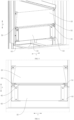
- FIG. 1 is a schematic view of the structure of the energy storing device provided in some embodiments of the present disclosure
- FIG. 2 is a partially exploded view of the energy storing device provided in some embodiments of the present disclosure.
- Some embodiments of the present disclosure provide an energy storing device 100, which comprises a box 10, at least one column of batteries 20, and at least one control box 30.
- the box 10 has a battery cabin 13.
- At least one column of batteries 20 is arranged inside the battery cabin 13, and each column of batteries 20 includes multiple batteries 20 arranged along the height direction of the box 10.
- At least one control box 30 is provided inside the battery cabin 13.
- Box 10 provides storage space for battery 20 and control box 30.
- Box 10 can be of a rectangular structure, with the height direction of box 10 extending in the Z direction as shown in the figure, the length direction of box 10 extending in the Y direction, and the width direction of box 10 extending in the X direction.
- Box 10 can be a prefabricated energy storing box, an energy storing container, etc.
- the box 10 can include a body and a cover, the body can be of a hollow structure with an opening 131 at one end, the cover is connected to the body and used to close the open end of the body, and the body and cover form a battery cabin 13.
- the body can also be of a hollow structure with openings at both opposite ends, with two sets of covers set up, each covering the two open ends of the body.
- box 10 can be adjusted adaptively.
- box 10 can be an energy storing container, and the size of the container can be an internationally recognized standard size, or customized as a non-standard size based on limitations such as the size of battery 20.
- Box 10 can be made of materials such as steel, aluminum, alloy, etc. that have certain structural strength and weight bearing capacity.
- Multiple batteries 20 are arranged in an orderly manner inside the battery cabin 13 along the height direction of the box 10 (in practical applications, the height direction of the box 10 can be perpendicular to the fixed plane or bearing plane of the energy storing device 100, and the height direction extends along the Z direction in the figure).
- the battery cabin 13 can have only one column of batteries 20 inside, or two, three, or even more columns of batteries 20 can also be set. Multiple columns of batteries 20 can be arranged along the length direction (Y direction shown in the figure) or the width direction (X direction shown in the figure) of box 10, or can be arranged in an array inside battery cabin 13.
- the control box 30 is of a box structure with control components, which can be PLC (Programmable Logic Controller).
- the control box 30 is used for electrical connection with one or more batteries 20, and can also be connected to the main control system. Specifically, control box 30 can read the voltage, current, temperature and other data of battery 20 during operation, and control the switch status of battery 20.
- control box 30 can be set to only one, which is electrical connected to all batteries 20 in battery cabin 13. Multiple control boxes 30 can also be set, and each control box 30 can be electrical connected to some batteries 20 in battery cabin 13.
- the battery 20 and control box 30 of the energy storing device 100 are both set inside the battery cabin 13 of the box 10, and their overall structure is simpler. Compared with the structure of the battery 20 and control box 30 being arranged in separate cabins, the structure of the energy storing device 100 can be simplified, thereby improving the assembly efficiency of the overall energy storing device 100.
- multiple batteries 20 in the battery cabin 13 are arranged along the height direction of the box 10, which facilitates the assembly, wiring, and other operations of the batteries 20, thereby further improving assembly efficiency.
- multiple batteries 20 are arranged along the height direction of the box 10, and the wiring harness arrangement of multiple batteries 20 is simpler and shorter, which can solve the problem of low space utilization rate caused by excessively long wiring harnesses.
- FIG. 3 is a front view of the energy storing device provided in some embodiments of the present disclosure
- FIG. 4 is a partially enlarged view of the part A shown in FIG. 2
- FIG. 5 is a schematic view of the structure of the batteries and control box installed inside the box shown in FIG. 4
- FIG. 6 is a partially enlarged view of the part B shown in FIG. 3
- FIG. 7 is a side view of the baffle shown in FIG. 6 .
- each control box 30 is electrically connected to one column of batteries 20, and the control box 30 is located below the corresponding column of batteries 20.
- the energy storing device 100 also includes a baffle 40, which is set between the control box 30 and at least one column of batteries 20 to protect the control box 30.
- control box 30 is equal to the number of columns of batteries 20, and each control box 30 is connected to one corresponding column of batteries 20. Control box 30 is located below one column of batteries 20 connected to the control box 30.
- the baffle 40 is set between the control box 30 and the batteries 20 located above the control box 30. Specifically, the baffle 40 is set between the control box 30 and one battery 20 adjacent to the control box 30.
- the baffle 40 is of a roughly plate-like structure, and can be made of metal or plastic materials.
- Baffle 40 is used to provide protection for control box 30.
- Baffle 40 can prevent impurities (such as liquid, dust, etc.) above control box 30 from falling on the main control box to affecting its use performance.
- impurities such as liquid, dust, etc.
- the condensation water is easy to be generated in the box 10 due to temperature differences, and condensation water droplets falling on the main control box can easily cause the main control box to be damp, thereby affecting the use performance of the main control box.
- the control box 30 is located below the corresponding battery 20, further improving the convenience of operation and maintenance of the control box 30, improving the assembly and wiring efficiency of the control box 30, and thus further improving the overall assembly efficiency of the energy storing device 100.
- a baffle 40 is arranged between the control box 30 and the battery 20 to prevent liquids (such as condensate liquid), pollutants, dust, and other impurities located above the control box 30 in the energy storing box 10 from falling into the control box 30. This provides good protection for the control box 30, improves its performance stability, and thus enhances the performance stability of the energy storing device 100.
- the projection of the baffle 40 at least partially covers the control box 30 along the height direction.
- the baffle 40 is located above the control box 30, and along the height direction of the box 10 (i.e., Z direction shown in FIG. 7 ), the projection of the baffle 40 on the control box 30 can cover a part of the control box 30.
- the projection of the baffle 40 on the control box 30 can only cover the area of the control box 30 where the impurities are easy to enter.
- the projection of baffle 40 on control box 30 can also fully cover control box 30.
- the baffle 40 is located above the control box 30, and the baffle 40 at least partially covers the control box 30, so that the baffle 40 plays a covering and protective role on the control box 30, thereby reducing the possibility of impurities falling into the control box 30 and improving the protective effect of the baffle 40.
- the projection of the baffle 40 completely covers the control box 30 along the height direction.
- the projection of the baffle 40 on the control box 30 completely covers the control box 30, and the control box 30 is fully in the shielding range along the Z direction of the baffle 40.
- the control box 30 is completely within the coverage range of the baffle 40, which is conducive to fully exerting the protective effect of the baffle 40 and further improving the performance stability of the control box 30.
- the energy storing device 100 further comprises a first bracket 50, which is arranged inside the battery cabin 13 and connected to the box 10.
- the first bracket 50 is configured to carry the battery 20, and the length of the baffle 40 is smaller than that of the first bracket 50.
- the first bracket 50 is a component used to support the battery 20.
- the first bracket 50 is located inside the battery cabin 13.
- the first bracket 50 can be directly connected to the box 10 or connected to other components set inside the box 10.
- a support frame 15 is provided inside the box 10, and the first bracket 50 can be connected to the support frame 15 inside the box 10.
- the number of first brackets 50 can be provided in multiple groups, with multiple groups of first brackets 50 distributed within battery cabin 13. Multiple groups of first brackets 50 can be arranged at intervals along the height direction of box 10 (i.e., Z direction in the figure) within the cabin of the battery 20. Each group of first brackets 50 can be used to support at least one battery 20.
- the first bracket 50 can be a boss connected to the support frame 15, wherein the boss has an upper surface along the height direction.
- the upper surface of the boss is used to contact the battery 20, and the boss supports the battery 20.
- the boss can be connected to the inner wall of the box 10 by welding, screwing, or other means.
- the length direction of the first bracket 50 extends along the length direction of battery 20.
- the length direction of battery 20 can extend along the width direction (X direction) of box 10, and the length of the first bracket 50 also extends along the X direction.
- the length of the first bracket 50 can be greater than, equal to, or less than the length of the battery 20.
- the length of baffle 40 also extends in the X direction. Along the X direction, the extension length of the first bracket 50 is greater than that of baffle 40. There can be gaps between the two opposite ends of baffle 40 in the X direction and the inner wall of the box 10.
- a first bracket 50 inside the box 10 is conducive to improving the convenience of installation and fixation of battery 20, improving the assembly efficiency of battery 20, and improving the fixation reliability of battery 20.
- the length of the baffle 40 is smaller than that of the first bracket 50, which can reduce the weight and size of the baffle 40, reduce material costs, and facilitate the weight reduction of the energy storing device 100.
- the baffle 40 comprises a first surface 43 facing the battery 20, and the first surface 43 is inclined relative to the height direction.
- the baffle 40 can have only the first surface 43 as an inclined plane, or the baffle 40 can also be of a flat structure as a whole, wherein the overall baffle 40 is inclined relative to the height direction, so that the first surface 43 is inclined relative to the height direction.
- the baffle 40 is of a flat structure as a whole, and the baffle 40 is inclined to make the first surface 43 of the baffle 40 as a bevel.
- the first surface 43 of the baffle 40 can gradually tilt downwards along any direction perpendicular to the height direction.
- the first surface 43 can gradually tilt downwards along the length direction (i.e., Y direction shown in the figure) of the box 10, or gradually tilt downwards along the width direction (i.e., X direction shown in the figure) of the box 10.
- the baffle can gradually tilt downwards along the width direction (i.e., X direction shown in the figure) of the box 10.
- the first surface 43 i.e., the upper surface of the baffle 40 along the height direction of the energy storing box 10) of the baffle 40 towards the battery 20 is tilted, and the liquid and other impurities that fall on the first surface 43 can slide from the lower edge of the first surface 43 to the bottom of the box 10 under the action of gravity, in order to achieve concentrate treatment at the bottom of the box 10 or timely discharge them from the energy storing box 10, reducing the risk of impurities (especially liquids) accumulating on the baffle 40, so as to alleviate the problem of increased moisture inside the box 10 caused by the accumulation of liquid on the baffle 40 and revaporization due to heating, which is conducive to maintaining dryness inside the box 10.
- the angle between the first surface 43 and the reference plane W is ⁇ , meeting 0° ⁇ ⁇ 30°, and the height direction is perpendicular to the reference plane W.
- the angle at which the first surface 43 tilts downwards relative to the reference plane W is ⁇ , and ⁇ can be any angle greater than 0° but less than or equal to 30°.
- ⁇ can be 5°, 10°, 15°, 20°, 25°, 30°, etc.
- ⁇ can be 2°.
- the reference plane W can be a horizontal plane.
- the angle between the first surface 43 and the reference plane perpendicular to the height direction of the energy storing box 10 is greater than zero degrees, allowing the first surface 43 to be tilted relative to the height direction of the energy storing box 10, thereby improving the smoothness and timeliness of the baffle 40 for discharging liquid.
- the structure of the baffle 40 needs to be increased, and the space occupied by the baffle 40 along the height direction of the energy storing box 10 will also be significantly increased, which is not conducive to improving the space utilization rate of the energy storing box 10 and thus not conducive to improving the energy density of the energy storing device 100. Controlling the angle between the first surface 43 and the reference plane within a range greater than zero but less than 30° can improve the smoothness and timeliness of the baffle 40 for discharging liquid and also increase the energy density of the energy storing device 100.
- the angle at which the first surface 43 tilts downwards relative to the reference plane W is ⁇ , and ⁇ can be any angle greater than 0.5° but less than or equal to 15°.
- ⁇ can be 0.5°, 0.8°, 3°, 5°, 8°, 10°, 12°, and 15°, etc.
- ⁇ can be 1°.
- the angle between the first surface 43 and the reference plane perpendicular to the height direction of the energy storing box 10 is controlled between 0.5° and 15°, which can further improve the smoothness and timeliness of liquid discharge. At the same time, it is beneficial to further improve the space utilization rate of the energy storing box 10, thereby increasing the energy density of the energy storing device 100.
- the energy storing device 100 comprises: a first limit member 70 and a second limit member 80, which are spaced apart along the height direction and connected to the box 10, wherein the baffle 40 is inserted between the first limit member 70 and the second limit member 80.
- the first limit member 70 and the second limit member 80 can be in conventional shapes such as block, column, plate, or other irregular structures, as long as a gap exists between the first limit member 70 and the second limit member 80 to accommodate the insertion of the baffle 40.
- both the first limit member 70 and the second limit member 80 are of a plate-like structure, with the large surfaces of the first limit member 70 and the second limit member 80 perpendicular to the height direction (Z direction).
- the surfaces of the first limit member 70 and the second limit member 80 facing the baffle 40 can be in direct contact with the baffle 40, or at least one of them can have a gap with the baffle 40.
- the first limit member 70 and the second limit member 80 can be separated and connected to the box 10 respectively.
- the first limit member 70 and the second limit member 80 can also be connected to each other as an integrated structure, which is connected to the box 10.
- the first limit member 70 and the second limit member 80 can be directly connected to the box 10, for example, the first limit member 70 and the second limit member 80 can be directly connected to the inner wall of the box 10.
- the first limit member 70 and the second limit member 80 can also be indirectly connected to the box 10.
- the first limit member 70 and the second limit member 80 can be connected to a component located inside the box 10, and such component is connected to the box 10.
- the setting positions of the first limit member 70 and the second limit member 80 can be flexibly set according to the insertion direction of the baffle 40.
- the baffle 40 is inserted between the control box 30 and the battery 20 along the Y direction.
- the first limit member 70 and the second limit member 80 can be set in two groups, with the two groups of first limit member 70 and second limit member 80 respectively located on two opposite sides of the baffle 40 along the X direction.
- the first limit member 70 and the second limit member 80 can also be set at the end of the baffle 40 in the Y direction. After the baffle 40 is inserted in the Y direction, one end of the baffle 40 in the Y direction is inserted between the first limit member 70 and the second limit member 80.
- the baffle 40 can be inserted into the box 10 from the open end of the body in the direction opposite to the open end of the body.
- the baffle 40 can be inserted into the box 10 along the X direction from the open end of the body.
- the first limit member 70 and the second limit member 80 can be set in two groups, with the two groups of first limit member 70 and second limit member 80 respectively arranged on two sides of the baffle 40 along the Y direction.
- the box 10 is provided therein with the first limit member 70 and the second limit member 80 arranged at intervals along the height direction of the box 10, and the baffle 40 is inserted between the first limit member 70 and the second limit member 80.
- the first limit member 70 and the second limit member 80 cooperate with each other to limit the relative position of the baffle 40 along the height direction, thereby limiting the baffle 40 inside the box 10 and reducing the possibility of the baffle 40 detaching from the installation position.
- the insertion method requires less installation space, which is easy to operate, and beneficial for improving the assembly convenience and assembly efficiency of energy storing device 100.
- the projection of the first limit member 70 on the baffle 40 and the projection of the second limit member 80 on the baffle 40 are staggered along the height direction.
- the first limit member 70 and the second limit member 80 are mutually staggered along the first direction.
- the first limit member 70 and the second limit member 80 are arranged on one side of the baffle 40 along the Y direction, and the first limit member 70 and the second limit member 80 are arranged in intervals along the X direction.
- the first limit member 70 and the second limit member 80 are misaligned along the Z direction.
- the first limit member 70 and second limit member 80 are staggered from each other, which can improve the stability of the first limit member 70 and second limit member 80 in limiting the baffle 40, and also reduce the extension length of the first limit member 70 and second limit member 80, save costs, and facilitate disassembly and assembly operations.
- FIG. 8 is a schematic view of the structure of the baffle and the second bracket provided in some embodiments of the present disclosure.
- the energy storing device 100 further includes a second bracket 60, which is arranged inside the battery cabin 13 and connected to the box 10.
- the second bracket 60 is configured to carry the control box 30, and the first limit member 70 and the second limit member 80 are connected to the second bracket 60.
- the second bracket 60 is a component used to support the control box 30.
- the second bracket 60 is located inside the battery cabin 13.
- the second bracket 60 can be directly connected to the box 10 or connected to other components set inside the box 10.
- a support frame 15 is provided inside the box 10, and the second bracket 60 can be connected to the inner-wall support frame 15 inside the box 10.
- the number of second brackets 60 can be provided in multiple groups, and each group of second brackets 60 can support correspondingly one control box 30.
- the implementation structure of the second bracket 60 can also be various.
- the second bracket 60 can include a support plate 611 and a connecting plate 612.
- the support plate 611 has an upper surface that intersects with the height direction, and the connecting plate 612 is connected to the upper surface of the support plate 611.
- the upper surface of the support plate 611 is used to contact and support the electric control box, and the connecting plate 612 is used to be connected with the support frame 15 through welding, screw connection, and other methods.
- the first limit member 70 and the second limit member 80 can be set at one end of the connecting plate 612 away from the support plate 611 to limit the baffle 40 above the control box 30 located on the support plate 611.
- the connecting plate 612 facing away from the support plate 611, there are two connecting sections 613 with varying heights along the height direction.
- the first limit member 70 and the second limit member 80 are respectively connected to one ends of the two connecting sections 613 facing away from the connecting plate 612.
- the first limit member 70 and the second limit member 80 can be fixed to the second bracket 60 by means of screw connection, riveting, welding, etc., or can be integrally formed with the second bracket 60.
- the second bracket 60 is arranged inside the box 10, which is conducive to improving the convenience of installing and fixing the control box 30, improving the assembly efficiency of the control box 30, and improving the reliability of fixing the control box 30.
- the first limit member 70 and second limit member 80 are integrated to the second bracket 60, with strong structural integration, which can further simplify the assembly process of energy storing device 100, reduce assembly difficulty, and improve the assembly efficiency of energy storing device 100.
- the energy storing device 100 further comprises a fastener 90, and the baffle 40 is detachably connected to the box 10 through the fastener 90.
- the baffle 40 can be detachably connected to the box 10 through fastener 90, thereby limiting the baffle 40.
- the baffle 40 may also be limited only by the first limit member 70 and the second limit member 80.
- the baffle 40 can be limited by the first limit member 70 and the second limit member 80, and also connected to the box 10 through a fastener 90 to further improve the stability for limiting the baffle 40.
- the position of fastener 90 can be flexibly set according to the position of baffle 40.
- fasteners can be any conventional connection structure such as bolts, clamps, ties, etc.
- the box 10 can include a body and a cover, the body can be of a hollow structure with an opening at one end, the cover is connected to the body and used to close the opening of the body, and the body and cover form a battery cabin.
- the baffle 40 can be inserted into the box 10 from the open end of the body towards the direction opposite to the open end of the body, and the fastener 90 can be located on one side of the baffle 40 facing the open end of the body, for more convenient disassembly and assembly operations.
- baffle 40 can be directly connected to the box 10 through the fastener 90, and the baffle 40 can also be connected to a structure connected to the box 10 and set inside the box 10 through the fastener 90.
- the energy storing device 100 includes a first bracket 50, which is used to support the battery 20"
- the baffle 40 can be connected to the first bracket 50 of the battery 20 adjacent to the control box 30 through fastener 90.
- FIG. 9 is a schematic view of the structure of a baffle connected to a first bracket provided in some embodiments of the present disclosure.
- the first bracket 50 is located above the control box 30, and the baffle 40 is set between the first bracket 50 and the control box 30.
- a connection structure of a fastener 90 i.e., the first extension part 45 mentioned below
- one side of the first bracket 50 along the X direction can be connected to an adapter support 51, wherein the adapter support 51 and the first extension part 45 are connected by fastener 90 to connect the baffle 40 to the first bracket 50.
- the energy storing device 100 includes a second bracket 60, which is used to support the battery 20
- the baffle 40 can be connected to the second bracket 60 by the fastener 90.
- the following text will provide a detailed introduction of the implementation structure of the baffle 40 connected to the second bracket 60.
- the baffle 40 and the second bracket 60 are connected by fastener 90, which can further improve the relative position stability of the baffle 40. Meanwhile, its fixing method is simple and easy to assemble and disassemble, which is conducive to improving the assembly efficiency of the overall energy storing device 100.
- the baffle 40 comprises a baffle body 44 and a first extension part 45, wherein the baffle body 44 is inserted between the first limit member 70 and the second limit member 80, and the first extension part 45 extends from the edge of the baffle body 44; and the energy storing device 100 further comprises a second bracket 60, wherein the second bracket 60 is arranged inside the battery cabin 13 and connected to the box 10, wherein the second bracket 60 is configured to support the control box 30, and the second bracket 60 comprises a bracket body 61 and a second extension part 62, wherein the second extension part 62 extends from the edge of the bracket body 61, and the first extension part 45 and the second extension part 62 are overlapped with each other and detachably connected through the fastener 90.
- the setting position of fastener 90 can be adaptively set according to the insertion direction of baffle 40 and the structure of the second bracket.
- one end of the box 10 in the X direction is an open end
- the first extension part 45 is located on one side of the baffle body 44 facing the open end in the X direction.
- the first extension part 45 is of a plate-like structure, and the large surface of the first extension part 45 is perpendicular to the Y direction.
- the second bracket 60 includes a support plate 611 and a connecting plate 612.
- the connecting plate 612 is connected to the upper surface of the support plate 611, the support plate 611 is used to support the electric control box, and the connecting plate 612 is screwed to the box 10 to fix the second bracket 60.
- Each electronic control box is supported by two second brackets 60, which are located on two opposite sides of the control box 30 in the Y direction.
- Each second bracket 60 is equipped with a first limit member 70 and a second limit member 80. The first limit member 70 and the second limit member 80 are located at one end of the connecting plate 612 away from the support plate 611 to limit the baffle 40 above the control box 30 located on the support plate 611.
- a second extension part 62 is set on one side of the connecting plate 612 facing the opening 131 end of the body.
- the second extension part 62 is also in the shape of a plate, and the second extension part 62 is overlapped with the first extension part 45 in the Y direction.
- the fastener 90 penetrates through the first extension part 45 and the second extension part 62 to connect the two.
- each second bracket 60 can be set with one second extension part 62.
- the baffle 40 can also be set with two first extension parts 45, and the two first extension parts 45 and two second extension parts 62 are connected in one-to-one correspondence.
- a bending part 6121 can be formed on one side of the connecting plate 612 facing the opening 131 end of the body, wherein the bending part 6121 extends in the Y direction.
- the second extension part 62 is provided on the bending part 6121, and the bending part 6121 can provide a connection surface for the control box 30.
- the control box 30 set on the second bracket 60 can be connected to the bending part 6121 through fastener 90 or other fasteners.
- the baffle 40 includes a first surface 43 facing the battery 20, which is inclined relative to the height direction
- the gap between the first limit member 70 and the second limit member 80 can be misaligned with the fastener 90 along the height direction, so that the baffle 40 can be inclined relative to the height direction as a whole.
- the baffle 40 is equipped with a first extension part 45
- the second bracket 60 is equipped with a second extension part 62.
- the first extension part 45 and the second extension part 62 are connected to each other, which can fix the relative position relationship between the baffle 40 and the second bracket 60, which is conducive to further improving the convenience of assembly operation and thus improving assembly efficiency.
- the baffle 40 comprises a substrate 41 and a first thermal insulating layer 42 stacked along the height direction.
- Substrate 41 can be made of materials with certain structural strength, such as hard plastic, metal, etc.
- the substrate 41 can be made of metal material.
- the first thermal insulating layer 42 can be made of any material with good heat insulation performance.
- the first thermal insulating layer 42 can be made of heat insulation materials with good water absorption, such as microcellular foaming polypropylene, polyurethane and other materials, or by directly using tripolycyanamide heat insulation cotton, melamine heat insulation cotton, acrylic heat insulation cotton, glass fiber cloth, high silica glass fiber cloth, ceramic fiber cotton, aerogel blanket, etc.
- the baffle 40 includes the baffle body 44 and the first extension part 45
- the substrate 41 and the first thermal insulating layer 42 can jointly form the baffle body 44 and be inserted between the first limit member 70 and the second limit member 80, and the first extension part 45 can extend from the substrate 41.
- the first thermal insulating layer 42 can reduce the temperature difference between the substrate 41 and the internal environment of the box 10, and play a thermal insulation role on the substrate 41, thereby reducing the amount of condensate water generated on the substrate 41, thereby reducing the risk of condensate water droplets generated on the substrate 41 falling on the control box 30 and causing the control box 30 to become damp, which is conducive to further improving the use performance of the control box 30.
- the first thermal insulating layer 42 is located on one side of the substrate 41 facing the control box 30.
- substrate 41 has two opposite surfaces along its thickness direction, one surface facing control box 30 and the other surface facing battery 20.
- the first thermal insulating layer 42 is provided at the surface on one side of substrate 41 facing control box 30.
- the first thermal insulating layer 42 can fully cover the substrate 41 or partially cover the substrate 41.
- the first thermal insulating layer 42 fully covers the surface of the substrate 41.
- the first thermal insulating layer 42 is located on one side of the substrate 41 facing the control box 30, which can further reduce the possibility of condensation water generated on the side of the baffle 40 facing the control box 30. Meanwhile, even if a small amount of condensate water is generated, the first thermal insulating layer 42 can assist in absorbing at least some of the condensate water, which is beneficial for further reducing the risk of moisture in the control box 30.
- the heat conductivity coefficient of the first thermal insulating layer 42 is T1, meeting T1 ⁇ 0.05W/m ⁇ K.
- the heat conductivity coefficient refers to the heat flux per unit temperature gradient. Specifically, heat conductivity coefficient refers to the amount of heat transferred through an area of 1 square meter under stable heat transfer conditions within a certain period, with a temperature difference of 1 degree (K, °C) on the surfaces of two sides of a 1m material. The unit thereof is watt/meter ⁇ degree (W/(m ⁇ K)), where K can be replaced by °C. It can be understood that the larger the heat conductivity coefficient is, the better the thermal conductivity of the first thermal insulating layer 42 is, and vice versa, the worse the thermal insulation performance is.
- the heat conductivity coefficient T1 of the first thermal insulating layer 42 can be any value less than or equal to 0.05W/m ⁇ K, for example, T1 can be 0.05W/m ⁇ K, 0.04W/m ⁇ K, 0.03W/m ⁇ K, 0.02W/m ⁇ K, etc.
- the heat conductivity coefficient of the first thermal insulating layer 42 is less than or equal to 0.05W/m ⁇ K, which is conducive to improving the insulation performance of the first thermal insulating layer 42, thereby improving the heat preservation effect of the first thermal insulating layer 42 on the substrate 41, and reducing the possibility of condensate water generated on the substrate 41.
- FIG. 10 is a front view of the energy storing device provided in some other embodiments of the present disclosure
- FIG. 11 is a partially enlarged view of the part C shown in FIG. 10 .
- Each control box 30 is electrically connected to one column of batteries 20, and the control box 30 is located above or below the corresponding column of batteries 20, wherein along the height direction, the control box 30 directly faces the battery 20 adjacent to the control box 30.
- one column of batteries 20 arranged along the height direction (Z direction shown in the figure) is electrically connected to the first control box 30, and the control box 30 can be located above or below the column of batteries 20.
- the outermost battery 20 along the height direction (Z direction shown in the figure) is adjacent to the control box 30.
- the control box 30 directly faces the battery 20 adjacent thereto, which means that there is no partition, baffle or other separate structures between the one battery 20 adjacent to the control box 30 and the control box 30, so that the control box 30 can directly face the battery 20.
- the control box 30 directly faces the adjacent battery 20, eliminating the isolation layer set between the control box 30 and the battery 20 in traditional energy storing devices 100, thereby simplifying the structure of the energy storing device 100, further simplifying the assembly process of the energy storing device 100, and improving the assembly efficiency of the energy storing device 100. It is also convenient to save material costs and space in the battery cabin 13.
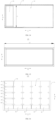
- FIG. 12 is a partially sectional side view of the box of the energy storing device shown in FIG. 3 ; and FIG. 13 is a top view of the box of the energy storing device shown in FIG. 3 .
- the box 10 includes a bottom wall 14, which includes a second thermal insulating layer 145.
- the bottom wall 14 is equipped with a second thermal insulating layer 145, which can be made of any material with good thermal insulation performance.
- the second thermal insulating layer 145 can be made of rock wool, asbestos, foam plastics, etc.
- the second thermal insulating layer 145 can be made of rock wool.
- the second thermal insulating layer 145 may be fixed to the outer surface of the bottom wall 14 of the box 10 by pasting, binding, or other means.
- the bottom wall 14 of the box 10 can be equipped with a filling chamber, and the second thermal insulating layer 145 can be filled in the filling chamber.
- the second thermal insulating layer 145 is installed on the bottom wall 14 of the box 10, which can provide good thermal insulation for the batteries 20 and control box 30 inside the box 10, and is conducive to improving the working performance of the batteries 20 and control box 30 in low-temperature environments.
- the second thermal insulating layer 145 is set on the bottom wall 14 of the box 10, which can prevent the second thermal insulating layer 145 from occupying the internal space of the battery cabin 13 compared to the method of setting it inside the battery cabin 13, which is conducive to improving the energy density of the energy storing device 100.
- the bottom wall 14 further comprises a first base plate 141 and a second base plate 146 arranged opposite to each other along the height direction, and the second thermal insulating layer 145 is arranged between the first base plate 141 and the second base plate 146.
- first base plate 141 and the second base plate 146 are spaced apart along the height direction of the box 10 (Z direction shown in the figure), and a filling cavity for filling the second thermal insulating layer 145 can be formed between the first base plate 141 and the second base plate 146.
- the second thermal insulating layer 145 is set in the filling cavity, and the first base plate 141, the second thermal insulating layer 145, and the second base plate 146 form a sandwich-like structure.
- the second thermal insulating layer 145 can be movably set between the first base plate 141 and the second base plate 146, or the second thermal insulating layer 145 can also be fixed between the first base plate 141 and the second base plate 146 through bonding or other methods.
- the second thermal insulating layer 145 is sandwiched between the first base plate 141 and the second base plate 146.
- the second thermal insulating layer 145 plays a thermal insulation role on the box 10.
- the first base plate 141 and the second base plate 146 improve the structural strength of the box 10 while providing protection for the second thermal insulating layer 145, thereby solving the problem of thermal insulation failure caused by pollution, wetting, and damage when the second thermal insulating layer 145 is exposed to the outside, and improving the thermal insulation effect of the second thermal insulating layer 145.
- the second base plate 146 is located below the first base plate 141, and at least part of the first base plate 141 is inclined relative to the height direction.
- the second base plate 146 is located below the first bottom plate 141 along the height direction of the box 10, and the first base plate 141 is located above the second base plate 146 along the height direction.
- the upper surface of the first base plate 141 can form the inner surface of the box 10.
- the inclined setting of the first base plate 141 can form an inclined surface on the upper surface of the first base plate 141, such that impurities such as sundries and liquids falling on the first base plate 141 in the box 10 can slide along the inclined surface of the first base plate 141 to facilitate the centralized treatment of impurities in the box 10.
- the first base plate 141 can gradually tilt downwards along the Y direction. Specifically, the first base plate 141 can gradually tilt downwards along a direction of one end of the Y direction pointing towards the other end, or the first base plate 141 can also gradually tilt downwards along a direction of the two opposite ends of the Y direction pointing towards the middle.
- the first base plate 141 can gradually tilt downwards along the X direction. Specifically, the first base plate 141 can gradually tilt downwards along a direction of one end of the X direction pointing towards the other end, or the first base plate 141 can also gradually tilt downwards along a direction of the two opposite ends of the X direction pointing towards the middle.
- the first base plate 141 can also be inclined along a direction of the edge towards the center, thereby forming a structure with a low center and a high outer circumference on the first base plate 141.
- At least part of the first base plate 141 is inclined relative to the height direction, such that impurities (especially liquids) falling on the first base plate 141 can accumulate towards lower positions in the height direction under the action of its own gravity, facilitating the collection and discharge of impurities.
- the bottom wall 14 further comprises: a first edge beam 147 and a second edge beam 148, spaced apart along the first direction; and an intermediate beam 149, arranged between the first edge beam 147 and the second edge beam 148, wherein the first edge beam 147, the second edge beam 148, and the intermediate beam 149 all extend in the second direction, and the first direction, the second direction, and the height direction are perpendicular to each other; and the first base plate 141 comprises a first sub-base plate 142 and a second sub-base plate 143, wherein the first sub-base plate 142 is connected to the first edge beam 147 and the intermediate beam 149, and the second sub-base plate 143 is connected to the second edge beam 148 and the intermediate beam 149.
- the first direction can extend along the X direction in the figure
- the second direction can extend along the Y direction in the figure.
- the first direction X can be the width direction or length direction of box 10.
- the second direction Y is the width direction of box 10.
- the second direction Y is the length direction of box 10.
- the first direction X is the width direction of box 10
- the second direction Y is the length direction of box 10.
- the first edge beam 147 and the second edge beam 148 are arranged opposite to each other along the first direction X, and the intermediate beam 149 is arranged between the first edge beam 147 and the second edge beam 148.
- the first edge beam 147, the second edge beam 148, and the intermediate beam 149 are arranged at intervals along the first direction X, and the length direction of the first edge beam 147, the second edge beam 148, and the intermediate beam 149 all extend along the second direction Y.
- the first base plate 141 includes a first sub-base plate 142 and a second sub-base plate 143.
- the first sub-base plate 142 and the second sub-base plate 143 are arranged side by side along the first direction X.
- the first sub-base plate 142 connects the first edge beam 147 and the intermediate beam 149
- the second sub-base plate 143 connects the second edge beam 148 and the intermediate beam 149.
- a second thermal insulating layer 145 can be installed between the first sub-base plate 142 and the second base plate 146, and between the second sub-base plate 143 and the second base plate 146.
- the first sub-base plate 142, the first edge beam 147, the intermediate beam 149, and the region of the second base plate 146 corresponding to the first sub-base plate 142 along the height direction can form one filling cavity for filling the second thermal insulating layer 145.
- the second sub-base plate 143, the second edge beam 148, the intermediate beam 149 and the region of the second base plate 146 corresponding to the second sub-base plate 143 along the height direction can form another filling cavity for filling the second thermal insulating layer 145.
- the first edge beam 147, second edge beam 148, and intermediate beam 149 form the main load-bearing beam of the box 10.
- the first base plate 141 is divided into two pieces of smaller size to reduce the assembly difficulty of the first base plate 141, which is beneficial for further improving the assembly efficiency of the energy storing device 100.
- the first edge beam 147, the second edge beam 148, and the intermediate beam 149 divide the space between the first base plate 141 and second base plate 146 into two subspaces to facilitate the filling of the second thermal insulating layer 145 in separate chambers.
- first sub-base plate 142 and second sub-base plate 143 respectively package the second thermal insulating layer 145 filled between the intermediate beam 149 and the first edge beam 147, and the second thermal insulating layer 145 filled between the intermediate beam 149 and the second edge beam 148, so as to improve the sealing performance of the second thermal insulating layer 145 packaged between the first base plate 141 and second base plate 146.
- the first sub-base plate 142 gradually tilts downwards along the direction of the first edge beam 147 pointing towards the intermediate beam 149.
- first edge beam 147 and the intermediate beam 149 are spaced apart along the first direction X, and the first sub-base plate 142 gradually slopes downwards along the direction of the first edge beam 147 pointing towards the intermediate beam 149.
- the upper surface of the first sub-base plate 142 forms an inclined plane that is inclined relative to the height direction, and along the height direction of the box 10, one end of the first sub-base plate 142 facing the first edge beam 147 is higher than the end of the first sub-base plate 142 facing the intermediate beam 149.
- impurities fall on the first sub-base plate 142 inside the box 10, they will slide towards the direction of the intermediate beam 149 under their own gravity, and can eventually accumulate at one end near the intermediate beam 149 of the first sub-base plate 142, or at the position of the intermediate beam 149, or enter the upper surface of the second sub-base plate 143 through the intermediate beam 149.
- the first sub-base plate 142 gradually tilts downwards, and the liquid and other impurities that fall on the first sub-base plate 142 converge towards the direction of the second sub-base plate 143, facilitating the concentration and treatment of impurities.
- the upper end of the first edge beam 147 extends beyond the upper end of the intermediate beam 149, and the first sub-base plate 142 connects the upper end of the first edge beam 147 and the upper end of the intermediate beam 149.
- the upper end of the intermediate beam 149 and the upper end of the first edge beam 147 are not flush to each other.
- the upper end of the first edge beam 147 is higher than the upper end of the intermediate beam 149.
- One end of the first sub-base plate 142 facing the intermediate beam 149 is connected to the upper end of the intermediate beam 149, and one end of the first sub-base plate 142 facing the first edge beam 147 is connected to the upper end of the first edge beam 147.
- the upper ends of the first edge beam 147 and the intermediate beam 149 are staggered in height.
- the first sub-base plate 142 can be connected to the upper end of the first edge beam 147 and the upper end of the intermediate beam 149 to achieve the tilting setting of the first sub-base plate 142.
- the installation of the first sub-base plate 142 plays a role in preventing errors and further improving assembly efficiency.
- the first sub-base plate 142 is connected to the upper ends of the first edge beam 147 and the intermediate beam 149, which can prevent the formation of large faults between the upper surface of the first sub-base plate 142 and the intermediate beam 149, thereby reducing the possibility of impurities of the first sub-base plate 142 accumulating near the intermediate beam 149 and improving the convenience of cleaning impurities from the box 10.
- the second base plate 146 may be connected to the lower ends of the intermediate beam 149, the first edge beam 147, and the second edge beam 148. Similar to the structure of the first base plate 141, two second base plates 146 can be provided, one of which connects the first edge beam 147 and the intermediate beam 149, and the other of which connects the intermediate beam 149 and the second edge beam 148.
- the intermediate beam 149 may be made of an I-beam, with the first base plate 141 connected to the upper crossbeam of the I-beam and the second base plate 146 connected to the vertical beam or lower crossbeam of the I-beam.
- the first edge beam 147 may be composed of two C type steels that are snapped in opposite directions. After the two C type steels are snapped, an inner cavity is formed, and the inner cavity can also be filled with thermal insulation material.
- the second edge beam 148 may be composed of two C type steels that are snapped in opposite directions. After the two C type steels are snapped, an inner cavity is formed, and the inner cavity can also be filled with thermal insulation material.
- the bottom wall 14 is provided with a drainage hole 1431 that passes through the second sub-base plate 143, the second thermal insulating layer 145, and the second base plate 146, wherein the drainage hole 1431 is configured to discharge the liquid inside the box 10.
- the first sub-base plate 142 is connected to the upper end of the intermediate beam 149, so the liquid dripping on the first sub-base plate 142 can enter the region of second sub-base plate 143 through the intermediate beam 149.
- the bottom wall 14 is equipped with a drainage hole 1431 that penetrates through the second sub-base plate 143, the second thermal insulating layer 145, and the second base plate 146, enabling the liquid accumulated from the first sub-base plate 142 to the second sub-base plate 143 and the liquid dripping on the second sub-base plate 143 to be discharged from the box 10 through the drainage hole 1431.
- one or multiple drainage holes 1431 can be set, as shown in FIG. 13 , multiple drainage holes 1431 can be set at intervals along the second direction Y on the second sub-base plate 143 to further improve the timeliness of drainage.
- the second sub-base plate 143 equipped with a drainage hole 1431 can be close to the open end of the box 10.
- the open end of the box 10 is located on one side of the box 10 along the X direction, and the second sub-base plate 143 and the first sub-base plate 142 are arranged side by side along the X direction.
- the second sub-base plate 143 is closer to the open end of the box 10 compared to the first sub-base plate 142, so as to facilitate manual construction and maintenance of drainage hole 1431.
- the drainage hole 1431 is set at the second sub-base plate 143 of the bottom wall 14, and liquid in the box 10 can be discharged from the box 10 through the drainage hole 1431 of the second sub-base plate 143, which is conducive to keeping the internal environment of the box 10 dry.
- the upper surface of the second sub-base plate 143 is inclined to guide the liquid on the upper surface to the drainage hole 1431.
- the second sub-base plate 143 is also inclined, and the drainage hole 1431 is located at the lower position of the second sub-base plate 143.
- the second sub-base plate 143 can tilt downwards in any direction relative to the height direction.
- the second sub-base plate 143 can gradually tilt downwards along the direction of the second edge beam 148 pointing towards the intermediate beam 149, and the drainage hole 1431 is set on one side of the second sub-base plate 143 near the intermediate beam 149.
- the second sub-base plate 143 can also gradually tilt downwards along the direction of the intermediate beam 149 towards the second edge beam 148, and the drainage hole 1431 is set on one side of the second sub-base plate 143 near the second edge beam 148.
- the drainage hole 1431 is set near the middle position along the first direction X at the second sub-base plate 143, and the edge of the second sub-base plate 143 gradually slopes downwards towards the drainage hole 1431.
- the upper surface of the first sub-base plate 142 forms an inclined plane that is inclined relative to the height direction, and along the height direction of the box 10, one end of the first sub-base plate 142 facing the first edge beam 147 is higher than the end of the first sub-base plate 142 facing the intermediate beam 149. If impurities fall on the first sub-base plate 142 inside the box 10, they will slide towards the direction of the intermediate beam 149 under their own gravity, and can eventually accumulate at one end near the intermediate beam 149 of the first sub-base plate 142, or at the position of the intermediate beam 149, or enter the upper surface of the second sub-base plate 143 through the intermediate beam 149.
- the upper surface of the second sub-base plate 143 is inclined, and the liquid flowing to the upper surface can quickly flow towards the position of the drainage hole 1431, further improving the drainage timeliness and smoothness of the box 10.
- the bottom wall 14 further comprises a sleeve 1410, wherein the sleeve 1410 is provided at the drainage hole 1431 for separating the liquid from the second thermal insulating layer 145.
- a second thermal insulating layer 145 is filled between the second sub-base plate 143 and the second base plate 146. If the liquid discharged through the drainage hole 1431 enters the second thermal insulating layer 145, it will wet the second thermal insulating layer 145 and affect its thermal insulation effect.
- the bottom wall 14 is equipped with a sleeve 1410, which is inserted into the drainage hole 1431.
- One end in the axial direction of the sleeve 1410 can be sealed with and connected to the second sub-base plate 143, and the other end can be sealed with and connected to the second base plate 146.
- the inner cavity of the sleeve 1410 forms a drainage channel, thereby separating the liquid from the second thermal insulating layer 145.
- the drainage hole 1431 is equipped with a sleeve 1410, which provides isolation and protection for the second thermal insulating layer 145 located between the first base plate 141 and the second base plate 146, thereby reducing the possibility of liquid discharged from the drainage hole 1431 wetting the second thermal insulating layer 145, and improving the thermal insulation effect of the second thermal insulating layer 145.
- the bottom wall 14 further comprises a support member 1411, which is provided between the first base plate 141 and the second base plate 146, and along the height direction Z, the support member 1411, the first base plate 141, and the second base plate 146 are spaced pairwise.
- the support member 1411 is used to support the second thermal insulating layer 145.
- the support member 1411 can have multiple implementation structures, and the support member 1411 can be in a plate-like structure arranged opposite to the first base plate 141, or can include multiple strip-type structures.
- the multiple strip-type structures are arranged at intervals along any direction perpendicular to the height direction (such as along the first direction X) to form the support member 1411.
- the support member 1411 can be fixedly connected to the edge of the bottom wall 14 through welding, screw connection, and other methods.
- a first sub-filling space can be formed between the support member 1411 and the first base plate 141, and a second sub-filling space can be formed between the support member 1411 and the second base plate 146. Both the first sub-filling space and the second sub-filling space are provided with a second thermal insulating layer 145.
- the support member 1411 is set between the first base plate 141 and the second base plate 146, and the support member 1411 divides the space between the first base plate 141 and the second base plate 146 and supports the partial second thermal insulating layer 145 filled between the first base plate 141 and second base plate 146, enabling the second thermal insulating layer 145 to stably and uniformly fill the space between the first base plate 141 and second base plate 146, thereby reducing the total filling amount of the second thermal insulating layer 145 and improving the thermal insulation effect of the second thermal insulating layer 145.
- the heat conductivity coefficient of the second thermal insulating layer 145 is T2, meeting T2 ⁇ 0.05W/m ⁇ K.
- the heat conductivity coefficient T2 of the second thermal insulating layer 145 can be any value less than or equal to 0.05W/m ⁇ K, for example, T2 can be 0.05W/m ⁇ K, 0.04W/m ⁇ K, 0.03W/m ⁇ K, 0.02W/m ⁇ K, etc.
- the heat conductivity coefficient of the second thermal insulating layer 145 is less than or equal to 0.05W/m ⁇ K, which is conducive to improving the thermal insulation performance of the second thermal insulating layer 145, thereby enhancing the thermal insulation effect of the second thermal insulating layer 145 on the internal environment of the box 10.
- the material of the second thermal insulating layer 145 is at least one of polyurethane foam or rock wool. Its materials are mature and have good heat preservation and thermal insulation effects, with strong practicality.
- box 10 is a standard container.
- Standard container refers to an international standard container, which is an internationally recognized standard container constructed and used in accordance with international standards.
- the dimensions of international standard containers can be divided into “external dimensions” and “minimum internal dimensions”.
- the standard container in this embodiment can be of any specification.
- a standard container can be a standard 20-foot container, with external dimensions of 6058mm in length x 2438mm in width x 2896mm in height.
- the box 10 is a standard container, which can be transported by directly using container transportation tools. It does not require secondary packaging with intermediate devices such as open top cabinets to be combined into standard sizes, making it easy to transport and have strong versatility.
- FIG. 14 is a sectional top view of the energy storing device provided in some embodiments of the present disclosure.
- the battery cabin 13 has an opening 131 in the first direction, and along the first direction, one battery 20 is provided in the battery cabin 13.
- the first direction extends along the X direction, and the first direction X can be either the width direction of box 10 or the length direction of box 10.
- the first direction X can be either the width direction of box 10 or the length direction of box 10.
- only one battery 20 is shown in FIG. 1 to illustrate the battery cabin 13.
- the battery cabin 13 is a compartment used to accommodate battery 20, which can enter the battery cabin 13 from the opening 131 of the battery cabin 13 along the first direction X.
- one battery 20 is installed in battery cabin 13, which can be understood as that only one battery 20 is arranged in the battery cabin 13 along the first direction X.
- the battery cabin 13 can have an opening 131 on one side in the first direction X, allowing two energy storing devices 100 to be adjacent, and the openings 131 of the battery cabins 13 of the two energy storing devices 100 can be set opposite to each other to improve the space utilization rate of the position where the energy storing device 100 is located.
- battery cabin 13 can also have openings 131 on both sides of the first direction X, and batteries 20 can be placed into or removed from the battery cabin 13 respectively from both sides of the first direction X.
- the battery 20 enters the battery cabin 13 through an opening 131 in the first direction.
- one battery 20 is installed in the battery cabin 13, so that the size of the battery 20 in the first direction can be larger.
- the size of the battery 20 in the first direction can be close to the size of the battery cabin 13 in the first direction, which can improve the space utilization rate of the battery cabin 13 in the first direction and make the energy storing device 100 have a higher energy density.
- FIG. 15 is a schematic view of the battery provided in some embodiments of the present disclosure.
- the size of the battery cabin 13 in the first direction is L1
- the size of the battery 20 in the first direction is L2, satisfying that L1 is less than 2L2.
- the dimension L1 of battery cabin 13 in the first direction X refers to the distance between the opening 131 of battery cabin 13 and the inner surface of the cabin wall located at one end of battery cabin 13 away from the opening 131 along the first direction X.
- Battery 20 is located inside battery cabin 13, and the relationship between the size L1 of battery cabin 13 in the first direction X and the size L2 of battery 20 in the first direction X meets: L1>L2.
- the ratio of the size L1 of the battery cabin 13 in the first direction to the size L2 of the battery 20 in the first direction meets L1 ⁇ 2L2, such that the size of the battery 20 in the first direction can be larger to make the space utilization rate of the battery cabin 13 in the first direction higher.
- L2/L1 can be any value between 95% and 100%.
- L2/L1 can be 95%, 95.4%, 96%, 96.8%, 97%, 97.6%, 98%, 98.8%, 99%, 99.5%, or 100%.
- the ratio between the size L1 of the battery cabin 13 in the first direction and the size L2 of the battery 20 in the first direction meets the above range, which can further improve the space utilization rate of the battery cabin 13 in the first direction and enable the energy storing device 100 to have a higher energy density.
- the ratio of L2/L1 can be any value between 98% and 99%.
- L2/L1 can be 98%, 98.1%, 98.2%, 98.25%, 98.3%, 98.4%, 98.5%, 98.6%, 98.7%, 98.8%, 98.9% or 99%.
- 1500mm ⁇ L1 ⁇ 2500mm 1500mm ⁇ L1 ⁇ 2500mm.
- L1 can be any value between 1500mm and 2500mm.
- L1 can be 1500mm, 1600mm, 1700mm, 1800mm, 1900mm, 2000mm, 2100mm, 2200mm, 2300mm, 2400mm or 2500mm.
- the size of the battery cabin 13 in the first direction meets the above range, and the battery cabin 13 has a larger accommodating space.
- the size of the battery 20 in the first direction can be larger, allowing the energy storing device 100 to have a higher energy density.
- 1600mm ⁇ L1 ⁇ 2400mm 1600mm ⁇ L1 ⁇ 2400mm.
- L1 can be any value between 1600mm and 2400mm.
- L1 can be 1600mm, 1650mm, 1700mm, 1750mm, 1800mm, 1850mm, 1900mm, 1950mm, 2000mm, 2050mm, 2100mm, 2150mm, 2200mm, 2250mm, 2300mm, 2350mm or 2400mm.
- the battery cabin 13 can have a larger capacity, and on the other hand, the space occupied by the battery cabin 13 in the first direction is smaller, making it easier to layout the energy storing box 10.
- 1500mm ⁇ L2 ⁇ 2500mm 1500mm ⁇ L2 ⁇ 2500mm.
- L2 can be any value between 1500mm and 2500mm.
- L2 can be 1500mm, 1600mm, 1700mm, 1800mm, 1900mm, 2000mm, 2100mm, 2200mm, 2300mm, 2400mm or 2500mm.
- the size of the battery 20 in the first direction meets the above range, in order to facilitate the battery 20 to match the size of the battery cabin 13 in the first direction, so that the energy storing device 100 can have a higher energy density.
- 1600mm ⁇ L2 ⁇ 2400mm 1600mm ⁇ L2 ⁇ 2400mm.
- L2 can be any value between 1600mm and 2400mm, and L2 can be 1600mm, 1700mm, 1800mm, 1900mm, 2000mm, 2100mm, 2200mm, 2300mm or 2400mm.
- the size of the battery 20 in the first direction is more suitable for assembly with the battery cabin 13, allowing the energy storing device 100 to have a higher energy density and facilitating the assembly of the battery 20 with other components (such as wiring harnesses).
- the first direction is the width direction of the box 10.
- the first direction extends along the X direction, and the first direction X is the width direction of the box 10.
- the first direction is the width direction of the energy storing box 10, such that the battery cabin 13 has a higher space utilization rate in the width direction of the energy storing box 10, in order to improve the overall space utilization rate of the battery cabin 13 and thus make the energy storing device 100 have a higher energy density.
- the length direction of the battery 20 is parallel to the first direction.
- the length direction of battery 20 is parallel to the width direction of energy storing box 10, making it easy for the length of battery 20 to match the width of energy storing box 10.
- battery 20 can more easily occupy as much internal space as possible in battery cabin 13, which is conducive to reducing the difficulty of assembling energy storing device 100 with high energy density.
- the box 10 includes a cabin 11 and a cabin door 12, wherein the cabin 11 has a battery cabin 13, the cabin door 12 is connected to the cabin 11, and the cabin door 12 is used to close the opening 131 of the battery cabin 13.
- the box 10 can include a body and a cover, the cabin 11 corresponds to the aforementioned body, and the cabin door 12 corresponds to the aforementioned cover.
- the cabin door 12 can be hinged to cabin 11 by a rotating mechanism such as a rotating shaft.
- the cabin door 12 rotates relative to cabin 11 to open or close the opening 131 of battery cabin 13.
- cabin door 12 may be connected to cabin 11 around an axis parallel to the height direction Z of energy storing box 10, so that cabin door 12 can rotate relative to cabin 11.
- the cabin door 12 closes the opening 131 of the battery cabin 13 to facilitate the isolation of the battery 20 and the control box 30 located inside the battery cabin 13 from the outside, so as to protect the battery 20 and the control box 30.
- FIG. 16 is a front view of the energy storing device provided in some other embodiments of the present disclosure.
- the energy storing device 100 comprises multiple columns of batteries 20 arranged in a second direction in the battery cabin 13; and multiple control boxes 30 are provided, and the multiple control boxes 30 are arranged along the second direction in the battery cabin 13, wherein each control box 30 is electrically connected to one column of batteries 20 and is located above or below the column of batteries 20, wherein the second direction is the length direction of the box 10.
- the control box 30 can be located above or below the battery 20. For example, all control boxes 30 are located below the battery 20, and multiple control boxes 30 are arranged along the Y direction in the battery cabin 13.
- the multiple columns of batteries 20 are installed inside the battery cabin 13, and multiple batteries 20 are arranged in a rectangular array, which makes more reasonable use of the space in the battery cabin 13 and facilitates the storage of more batteries 20 in the battery cabin 13, further improving the space utilization rate of the battery cabin 13.
- the number of cabin doors 12 is multiple, and multiple cabin doors 12 can be rotatably connected to the cabin 11.
- the cabin doors 12 are arranged along the length direction of the energy storing box 10.
- each cabin door 12 can correspond to multiple batteries 20 in one column to facilitate the assembly of battery 20 and control box 30.
- the battery 20 may include a battery 20 box and multiple battery 20 cells accommodated within the battery 20 box, with at least two battery 20 cells connected in parallel among the multiple battery 20 cells.
- connection between the individual cells of battery 20 is an electrical connection to facilitate the transmission of current.
- the material of the battery 20 box of battery 20 is aluminum, for example, AL6061.
- AL6061 is an aluminum alloy material that can be strengthened by heat treatment. It has good formability, weldability, and machinability, as well as moderate strength, and can still maintain good operability after annealing.
- some embodiments of the present disclosure provide an energy storing device 100, which includes a box 10, multiple columns of batteries 20, and multiple control boxes 30.
- the box 10 is a standard container, and includes a cabin 11 and a cabin door 12.
- the cabin 11 has a battery cabin 13, and the battery cabin 13 has an opening 131 on one side of the box 10 in the width direction (X direction in the figure).
- the cabin door 12 is connected to the cabin 11, and the cabin door 12 is used to close the opening 131 of the battery cabin 13.
- the box 10 includes a bottom wall 14 (i.e., the bottom wall 14 of the cabin 11), and the bottom wall 14 includes a first base plate 141 and a second base plate 146 arranged opposite to each other along the height direction (Z direction in the figure) of the box 10, and a second thermal insulating layer 145 arranged between the first base plate 141 and the second base plate 146, and also includes a first edge beam 147, a intermediate beam 149, and a second edge beam 148 arranged at intervals along the width direction (X direction in the figure) of the box 10, wherein the second edge beam 148 is closer to the opening 131 of the battery cabin 13 compared to the first edge beam 147.
- the first base plate 141 is located above the second base plate 146, and includes the first sub-base plate 142 and the second sub-base plate 143 arranged in the X direction.
- the upper end of the first edge beam 147 extends beyond the upper end of the intermediate beam 149 along the height direction.
- the first sub-base plate 142 connects the upper end of the first edge beam 147 and the upper end of the intermediate beam 149, so that the first sub-base plate 142 gradually tilts downwards along the direction of the first edge beam 147 pointing towards the intermediate beam 149.
- the second sub-base plate 143 is connected to the upper end of the intermediate beam 149 and the upper end of the first edge beam 147.
- the bottom wall 14 is equipped with a drainage hole 1431 that runs through the second sub-base plate 143, the second thermal insulating layer 145, and the second base plate 146.
- the drainage hole 1431 is used to discharge the liquid inside the box 10.
- the upper surface of the second sub-base plate 143 is inclined to guide the liquid on the upper surface to the drainage hole 1431.
- the second base plate 146 is connected to the lower ends of the first edge beam 147, the second edge beam 148, and the intermediate beam 149.
- Multiple columns of batteries 20 are arranged along the length direction (Y direction) of the box 10, and multiple batteries 20 in each column are arranged along the height direction (Z direction) of the box 10.
- One control box 30 is arranged correspondingly and located below each column of batteries 20 in the cabin for the battery 20, and the control box 30 is electrically connected to one row of batteries 20 located above the control box 30.
- control box 30 directly faces battery 20 adjacent thereto.
- some embodiments of the present disclosure provide an energy storing device 100, which includes a box 10, multiple columns of batteries 20, multiple control boxes 30, and a baffle 40.
- the box 10 is a standard container, and includes a cabin 11 and a cabin door 12.
- the cabin 11 has a battery cabin 13, and the battery cabin 13 has an opening 131 on one side of the box 10 in the width direction (X direction in the figure).
- the cabin door 12 is connected to the cabin 11, and the cabin door 12 is used to close the opening 131 of the battery cabin 13.
- the box 10 includes a bottom wall 14 (i.e., the bottom wall 14 of the cabin 11), and the bottom wall 14 includes a first base plate 141 and a second base plate 146 arranged opposite to each other along the height direction (Z direction in the figure) of the box 10, and a second thermal insulating layer 145 arranged between the first base plate 141 and the second base plate 146, and also includes a first edge beam 147, a intermediate beam 149, and a second edge beam 148 arranged at intervals along the width direction (X direction in the figure) of the box 10, wherein the second edge beam 148 is closer to the opening 131 of the battery cabin 13 compared to the first edge beam 147.
- the first base plate 141 is located above the second base plate 146, and includes the first sub-base plate 142 and the second sub-base plate 143 arranged in the X direction.
- the upper end of the first edge beam 147 extends beyond the upper end of the intermediate beam 149 along the height direction.
- the first sub-base plate 142 connects the upper end of the first edge beam 147 and the upper end of the intermediate beam 149, so that the first sub-base plate 142 gradually tilts downwards along the direction of the first edge beam 147 pointing towards the intermediate beam 149.
- the second sub-base plate 143 is connected to the upper end of the intermediate beam 149 and the upper end of the first edge beam 147.
- the bottom wall 14 is equipped with a drainage hole 1431 that runs through the second sub-base plate 143, the second thermal insulating layer 145, and the second base plate 146.
- the drainage hole 1431 is used to discharge the liquid inside the box 10.
- the upper surface of the second sub-base plate 143 is inclined to guide the liquid on the upper surface to the drainage hole 1431.
- the second base plate 146 is connected to the lower ends of the first edge beam 147, the second edge beam 148, and the intermediate beam 149.
- Multiple columns of batteries 20 are arranged along the length direction (Y direction) of the box 10, and multiple batteries 20 in each column are arranged along the height direction (Z direction) of the box 10.
- One control box 30 is arranged correspondingly and located below each column of batteries 20 in the cabin for the battery 20, and the control box 30 is electrically connected to one row of batteries 20 located above the control box 30.
- baffles 40 There are also multiple baffles 40, and one baffle 40 is set between each column of batteries 20 and the control box 30 located below the column of batteries 20.
- the baffle 40 includes a first surface 43 facing the battery 20, and the first surface 43 is inclined relative to the height direction.
- the energy storing device 100 also includes a second bracket 60, which is arranged inside the battery cabin 13 and connected to the box 10.
- the second bracket 60 includes a bracket body 61 and a second extension part 62, wherein the bracket body 61 are used to support the control box 30, and the second extension part 62 is set at one end of the bracket body 61 near the opening 131 of the battery cabin 13 in the X direction.
- the bracket body 61 is connected to a first limit member 70 and a second limit member 80 set opposite to each other in the height direction of the box 10.
- the baffle 40 includes a baffle body 44 and a first extension part 45.
- the two ends of the baffle body 44 are inserted between the first limit member 70 and the second limit member 80 in the Y direction.
- the first extension part 45 is located at one end of the baffle body 44 near the opening 131 of the battery cabin 13 in the X direction.
- the first extension part 45 is overlapped with the second extension part 62 and connected by bolts, and along the width direction (X direction) of the box 10, the projection of the central axis of the bolts on the box 10 is located above the projection of the gap between the first limit member 70 and the second limit member 80 on the box 10, in order to tilt the baffle body 44 relative to the height direction.
Landscapes
- Chemical & Material Sciences (AREA)
- Chemical Kinetics & Catalysis (AREA)
- Electrochemistry (AREA)
- General Chemical & Material Sciences (AREA)
- Engineering & Computer Science (AREA)
- Manufacturing & Machinery (AREA)
- Microelectronics & Electronic Packaging (AREA)
- Battery Mounting, Suspending (AREA)
Abstract
Description
- The present disclosure claims the priority to the PCT international application with the filing No.
PCT/CN2022/123362 filed on September 30, 2022 PCT/CN2022/123432 filed on September 30, 2022 - The present disclosure relates to the technology field of energy storing device, and in particular to an energy storing device.
- Due to the widespread demand for clean energy in the market, energy storing devices have been widely used. In prior art, energy storing devices have complex structures and low assembly efficiency. Therefore, how to improve the assembly efficiency of energy storing devices is an urgent problem to be solved.
- The present disclosure provides an energy storing device, which is convenient for improving assembly efficiency.
- In the first aspect, the present disclosure provides an energy storing device, comprising: a box, having a battery cabin; at least one column of batteries, arranged inside the battery cabin, wherein each column of batteries comprises multiple batteries arranged along the height direction of the box; and at least one control box, arranged inside the battery cabin.
- In the technical solution of the present disclosure, the battery and control box of the energy storing device are both set inside the battery cabin of the box, and their overall structure is simpler. Compared with the structure of the battery and control box being arranged in separate cabins, the structure of the energy storing device can be simplified, thereby improving the assembly efficiency of the overall energy storing device. At the same time, multiple batteries in the battery cabin are arranged along the height direction of the box, which facilitates the assembly, wiring, and other operations of the batteries, thereby further improving assembly efficiency. In addition, multiple batteries are arranged along the height direction of the box, such that the wiring harness arrangement of multiple batteries is simpler and shorter, which can solve the problem of low space utilization rate caused by excessively long wiring harnesses. For overall energy storing device, it simplifies the structure, improves assembly efficiency, and also improves space utilization rate.
- According to some embodiments of the present disclosure, each control box is electrically connected to one column of batteries, the control box is located below the corresponding column of batteries, and the energy storing device further comprises a baffle, arranged between the control box and at least one column of batteries for protecting the control box.
- In the above technical solution, the control box is located below the corresponding battery, further improving the convenience of operation and maintenance of the control box, improving the assembly and wiring efficiency of the control box, and thus further improving the overall assembly efficiency of the energy storing device. A baffle is installed between the control box and the battery to prevent liquids (such as condensate liquid), pollutants, dust, and other impurities located above the control box in the energy storing device from falling into the control box. This provides good protection for the control box, improves its performance stability, and thus enhances the performance stability of the energy storing device.
- According to some embodiments of the present disclosure, the projection of the baffle at least partially covers the control box along the height direction.
- In the above technical solution, the baffle is located above the control box, and the baffle at least partially covers the control box, so that the baffle plays a covering and protective role on the control box, thereby reducing the possibility of impurities falling into the control box and improving the protective effect of the baffle.
- According to some embodiments of the present disclosure, the projection of the baffle completely covers the control box along the height direction.
- In the above technical solution, the projection of the baffle completely covers the control box, that is, the control box is completely within the coverage range of the baffle, which is conducive to fully exerting the protective effect of the baffle and further improving the performance stability of the control box.
- According to some embodiments of the present disclosure, the energy storing device further comprises a first bracket, wherein the first bracket is arranged inside the battery cabin and connected to the box, the first bracket is configured to carry the battery, and the length of the baffle is less than the length of the first bracket.
- In the above technical solution, setting a first bracket inside the box is conducive to improving the convenience of installation and fixation of battery, improving the assembly efficiency of battery, and improving the fixation reliability of battery. The length of the baffle is smaller than that of the first bracket, which can reduce the weight and size of the baffle, reduce material costs, and facilitate the weight reduction of the energy storing device.
- According to some embodiments of the present disclosure, the baffle comprises a first surface facing the battery, wherein the first surface is inclined relative to the height direction.
- In the above technical solution, the first surface (i.e., the upper surface of the baffle along the height direction of the energy storing box) of the baffle towards the battery is tilted, and the liquid and other impurities that fall on the first surface can slide from the lower edge of the first surface to the bottom of the box under the action of gravity, in order to achieve concentrate treatment at the bottom of the box or timely discharge them from the energy storing box, reducing the risk of impurities (especially liquids) accumulating on the baffle, so as to alleviate the problem of increased moisture inside the box caused by the accumulation of liquid on the baffle and revaporization due to heating, which is conducive to maintaining dryness inside the box.
- According to some embodiments of the present disclosure, the angle between the first surface and the reference plane is α, meeting 0° < α≤ 30°, and the height direction is perpendicular to the reference plane.
- In the above technical solution, the angle between the first surface and the reference plane perpendicular to the height direction of the energy storing box is greater than zero degrees, allowing the first surface to be tilted relative to the height direction of the energy storing box, thereby improving the smoothness and timeliness of the baffle for discharging liquid. At the same time, if the inclination angle of the baffle is too large, while ensuring the coverage area of the baffle on the control box, the structure of the baffle needs to be increased, and the space occupied by the baffle along the height direction of the energy storing box will also be significantly increased, which is not conducive to improving the space utilization rate of the energy storing box and thus not conducive to improving the energy density of the energy storing device. Controlling the angle between the first surface and the reference plane within a range greater than zero but less than 30° can improve the smoothness and timeliness of the baffle for discharging liquid and also increase the energy density of the energy storing device.
- According to some embodiments of the present disclosure, 0.5° ≤ α≤ 15°.
- In the above technical solution, the angle between the first surface and the reference plane perpendicular to the height direction of the energy storing box is controlled between 0.5° and 15°, which can further improve the smoothness and timeliness of liquid discharge. At the same time, it is beneficial to further improve the space utilization rate of the energy storing box, thereby increasing the energy density of the energy storing device.
- According to some embodiments of the present disclosure, the energy storing device comprises: a first limit member and a second limit member, spaced apart along the height direction and connected to the box, wherein the baffle is inserted between the first limit member and the second limit member.
- In the above technical solution, the box is provided therein with the first limit member and the second limit member arranged at intervals along the height direction of the box, and the baffle is inserted between the first limit member and the second limit member. The first limit member and the second limit member cooperate with each other to limit the relative position of the baffle along the height direction, thereby limiting the baffle inside the box and reducing the possibility of the baffle detaching from the installation position. At the same time, the insertion method requires less installation space, which is easy to operate, and beneficial for improving the assembly convenience and assembly efficiency of energy storing device.
- According to some embodiments of the present disclosure, the projection of the first limit member on the baffle and the projection of the second limit member on the baffle are staggered along the height direction.
- In the above technical solution, the first limit member and second limit member are staggered from each other, which can improve the stability of the first limit member and second limit member in limiting the baffle, and also reduce the extension length of the first and second limit members, save costs, and facilitate disassembly and assembly operations.
- According to some embodiments of the present disclosure, the energy storing device further comprises a second bracket, wherein the second bracket is arranged inside the battery cabin and connected to the box, the second bracket is configured to carry the control box, and the first limit member and the second limit member are connected to the second bracket.
- In the above technical solution, a second bracket is installed inside the box, which is conducive to improving the convenience of installing and fixing the control box, improving the assembly efficiency of the control box, and improving the reliability of fixing the control box. The first and second limit members are integrated into the second bracket, with strong structural integration, which can further simplify the assembly process of energy storing device, reduce assembly difficulty, and improve the assembly efficiency of energy storing device.
- According to some embodiments of the present disclosure, the energy storing device further comprises a fastener, and the baffle is detachably connected to the box through the fastener.
- In the above technical solution, the baffle and the box are connected by fasteners, which can further improve the relative position stability of the baffle. Meanwhile, its fixing method is simple and easy to assemble and disassemble, which is conducive to improving the assembly efficiency of the overall energy storing device.
- According to some embodiments of the present disclosure, the baffle comprises a baffle body and a first extension part, wherein the baffle body is inserted between the first limit member and the second limit member, and the first extension part extends from the edge of the baffle body; and the energy storing device further comprises a second bracket, wherein the second bracket is arranged inside the battery cabin and connected to the box, wherein the second bracket is configured to support the control box, and the second bracket comprises a bracket body and a second extension part, wherein the second extension part extends from the edge of the bracket body, and the first extension part and the second extension part are overlapped with each other and detachably connected through the fastener.
- In the above technical solution, the baffle is equipped with a first extension part, and the second bracket is equipped with a second extension part. The first extension part and the second extension part are connected to each other, which can fix the relative position relationship between the baffle and the second bracket, which is conducive to further improving the convenience of assembly operation and thus improving assembly efficiency.
- According to some embodiments of the present disclosure, the baffle comprises a substrate and a first thermal insulating layer stacked along the height direction.
- In the above technical solution, the first thermal insulating layer can reduce the temperature difference between the substrate and the internal environment of the box, and play a thermal insulation role on the substrate, thereby reducing the amount of condensate water generated on the substrate, thereby reducing the risk of condensate water droplets generated on the substrate falling on the control box and causing the control box to become damp, which is conducive to further improving the use performance of the control box.
- According to some embodiments of the present disclosure, the first thermal insulating layer is located on one side of the substrate facing the control box.
- In the above technical solution, the first thermal insulating layer is located on the side of the substrate facing the control box, which can further reduce the possibility of condensation water generated on the side of the baffle facing the control box. Meanwhile, even if a small amount of condensate water is generated, the first thermal insulating layer can assist in absorbing at least some of the condensate water, which is beneficial for further reducing the risk of moisture in the control box.
- According to some embodiments of the present disclosure, the heat conductivity coefficient of the first thermal insulating layer is T1, meeting T1 ≤ 0.05W/m·K.
- In the above technical solution, the heat conductivity coefficient of the first thermal insulating layer is less than or equal to 0.05W/m·K, which is conducive to improving the insulation performance of the first thermal insulating layer, thereby improving the heat preservation effect of the first thermal insulating layer on the substrate, and reducing the possibility of condensate water generated on the substrate.
- According to some embodiments of the present disclosure, each control box is electrically connected to one column of batteries, and the control box is located above or below the corresponding column of batteries, wherein along the height direction, the control box directly faces the batteries adjacent to the control box.
- In the above technical solution, the control box directly faces the adjacent battery, eliminating the isolation layer set between the control box and the battery in traditional energy storing devices, thereby simplifying the structure of the energy storing device, further simplifying the assembly process of the energy storing device, and improving the assembly efficiency of the energy storing device.
- According to some embodiments of the present disclosure, the box comprises a bottom wall, which includes a second thermal insulating layer.
- In the above technical solution, a second thermal insulating layer is installed on the bottom wall of the box, which can provide good thermal insulation for the batteries and control box inside the box, and is conducive to improving the working performance of the batteries and control box in low-temperature environments. At the same time, the second thermal insulating layer is set on the bottom wall of the box, which can prevent the second thermal insulating layer from occupying the internal space of the battery cabin compared to the method of setting it inside the battery cabin, which is conducive to improving the energy density of the energy storing device.
- According to some embodiments of the present disclosure, the bottom wall further comprises a first base plate and a second base plate arranged opposite to each other along the height direction, and the second thermal insulating layer is arranged between the first base plate and the second base plate.
- In the above technical solution, the second thermal insulating layer is sandwiched between the first base plate and the second base plate. The second thermal insulating layer plays a thermal insulation role on the box. At the same time, the first base plate and the second base plate improve the structural strength of the box while providing protection for the second thermal insulating layer, thereby solving the problem of thermal insulation failure caused by pollution, wetting, and damage when the second thermal insulating layer is exposed to the outside, and improving the thermal insulation effect of the second thermal insulating layer.
- According to some embodiments of the present disclosure, the second base plate is located below the first base plate, and at least part of the first base plate is inclined relative to the height direction.
- In the above technical solution, at least part of the first base plate is inclined relative to the height direction, such that impurities (especially liquids) falling on the first base plate can accumulate towards lower positions in the height direction under the action of its own gravity, facilitating the collection and discharge of impurities.
- According to some embodiments of the present disclosure, the bottom wall further comprises: a first edge beam and a second edge beam, spaced apart along the first direction; and an intermediate beam, arranged between the first edge beam and the second edge beam, wherein the first edge beam, the second edge beam, and the intermediate beam all extend in the second direction, and the first direction, the second direction, and the height direction are perpendicular to each other; and the first base plate comprises a first sub-base plate and a second sub-base plate, wherein the first sub-base plate is connected to the first edge beam and the intermediate beam, and the second sub-base plate is connected to the second edge beam and the intermediate beam.
- In the above technical solution, the first edge beam, second edge beam, and intermediate beam form the main load-bearing beam of the box. The first base plate is divided into two pieces of smaller size to reduce the assembly difficulty of the first base plate, which is beneficial for further improving the assembly efficiency of the energy storing device. At the same time, the first edge beam, the second edge beam, and the intermediate beam divide the space between the first and second base plates into two subspaces to facilitate the filling of the second thermal insulating layer in separate chambers. Moreover, the first sub-base plate and second sub-base plate respectively package the second thermal insulating layer filled between the intermediate beam and the first edge beam, and the second thermal insulating layer filled between the intermediate beam and the second edge beam, so as to improve the sealing performance of the second thermal insulating layer packaged between the first and second base plates.
- According to some embodiments of the present disclosure, the first sub-base plate gradually tilts downwards along the direction of the first edge beam pointing towards the intermediate beam.
- In the above technical solution, the first sub-base plate gradually tilts downwards, and the liquid and other impurities that fall on the first sub-base plate converge towards the direction of the second sub-base plate, facilitating the concentration and treatment of impurities.
- According to some embodiments of the present disclosure, along the height direction, the upper end of the first edge beam extends beyond the upper end of the intermediate beam, and the first sub-base plate connects the upper end of the first edge beam and the upper end of the intermediate beam.
- In the above technical solution, the upper ends of the first edge beam and the intermediate beam are staggered in height. The first sub-base plate can be connected to the upper end of the first edge beam and the upper end of the intermediate beam to achieve the tilting setting of the first sub-base plate. The installation of the first sub-base plate plays a role in preventing errors and further improving assembly efficiency. At the same time, the first sub-base plate is connected to the upper ends of the first edge beam and the intermediate beam, which can prevent the formation of large faults between the upper surface of the first sub-base plate and the intermediate beam, thereby reducing the possibility of impurities of the first sub-base plate accumulating near the intermediate beam and improving the convenience of cleaning impurities from the box.
- According to some embodiments of the present disclosure, the bottom wall is provided with a drainage hole that passes through the second sub-base plate, the second thermal insulating layer, and the second base plate, wherein the drainage hole is configured to discharge the liquid inside the box.
- In the above technical solution, a drainage hole is set at the second sub-base plate of the bottom wall, and liquid can be discharged from the box through the drainage hole of the second sub-base plate, which is conducive to keeping the internal environment of the box dry.
- According to some embodiments of the present disclosure, the upper surface of the second sub-base plate is inclined to guide the liquid on the upper surface to the drainage hole.
- In the above technical solution, the upper surface of the second sub-base plate is inclined, and the liquid flowing to the upper surface can quickly flow towards the position of the drainage hole, further improving the drainage timeliness and smoothness of the box.
- According to some embodiments of the present disclosure, the bottom wall further comprises a sleeve, wherein the sleeve is provided at the drainage hole for separating the liquid from the second thermal insulating layer.
- In the above technical solution, a sleeve is set up for the drainage hole, which plays an isolation and protection role on the second thermal insulating layer set between the first and second base plates, reducing the possibility of the liquid discharged from the drainage hole wetting the second thermal insulating layer, thereby improving the thermal insulation effect of the second thermal insulating layer.
- According to some embodiments of the present disclosure, the bottom wall further comprises: a support member arranged between the first base plate and the second base plate, wherein along the height direction, the support member and the first base plate are arranged at intervals and the support member and the second base plate are arranged at intervals, and the support member is configured to support the second thermal insulating layer.
- In the above technical solution, a support member is set between the first base plate and the second base plate, and the support member supports the partial second thermal insulating layer filled between the first base plate and second base plate, enabling the second thermal insulating layer to stably and uniformly fill the space between the first base plate and second base plate, thereby reducing the total filling amount of the second thermal insulating layer and improving the thermal insulation effect of the second thermal insulating layer.
- According to some embodiments of the present disclosure, the heat conductivity coefficient of the second thermal insulating layer is T2, meeting T2 ≤ 0.05W/m·K.
- In the above technical solution, the heat conductivity coefficient of the second thermal insulating layer is less than or equal to 0.05W/m·K, which is conducive to improving the thermal insulation performance of the second thermal insulating layer, thereby enhancing the thermal insulation effect of the second thermal insulating layer on the internal environment of the box.
- According to some embodiments of the present disclosure, the material of the second thermal insulating layer is at least one of polyurethane foam or rock wool.
- In the above technical solution, the second thermal insulating layer can use at least one of polyurethane foam or rock wool, which has mature materials, good thermal insulation effect, and strong practicality.
- According to some embodiments of the present disclosure, the box is a standard container.
- In the above technical solution, the box is a standard container, which can be transported directly by using container transportation tools. It does not require secondary packaging with intermediate devices such as open top cabinets to be combined into standard sizes, making it easy to transport and have strong versatility.
- According to some embodiments of the present disclosure, the battery cabin has an opening in a first direction, and along the first direction, the battery cabin is provided with one battery.
- In the above technical solution, the battery enters the battery cabin through an opening in the first direction. Along the first direction, one battery is installed in the battery cabin, so that the size of the battery in the first direction can be larger. For example, the size of the battery in the first direction can be close to the size of the battery cabin in the first direction, which can improve the space utilization rate of the battery cabin in the first direction and make the energy storing device have a higher energy density.
- According to some embodiments of the present disclosure, the size of the battery cabin in the first direction is L1, and the size of the battery in the first direction is L2, satisfying that L1 is less than 2L2.
- In the above technical solution, the ratio of the size L1 of the battery cabin in the first direction to the size L2 of the battery in the first direction meets L1<2L2, such that the size of the battery in the first direction can be larger to make the space utilization rate of the battery cabin in the first direction higher.
- According to some embodiments of the present disclosure, 95% ≤ L2/L1 ≤ 100%.
- In the above technical solution, the ratio between the size L1 of the battery cabin in the first direction and the size L2 of the battery in the first direction meets the above range, which can further improve the space utilization rate of the battery cabin in the first direction and enable the energy storing device to have a higher energy density.
- According to some embodiments of the present disclosure, 98% ≤ L2/L1 ≤ 99%.
- In the above technical solution, compared to 95% ≤ L2/L1 ≤ 100%, when 98% ≤ L2/L1 ≤ 99%, it can ensure that the battery cabin has a higher space utilization rate in the first direction, and also facilitate the reservation of assembly space between the battery and other components, thereby reducing interference between the battery and other components.
- According to some embodiments of the present disclosure, 1500mm ≤ L1 ≤ 2500mm.
- In the above technical solution, the size of the battery cabin in the first direction meets the above range, and the battery cabin has a larger accommodating space. The size of the battery in the first direction can be larger, allowing the energy storing device to have a higher energy density.
- According to some embodiments of the present disclosure, 1600mm ≤ L1 ≤ 2400mm.
- In the above technical solution, compared to 1500mm ≤ L1 ≤ 2500mm, when 1600mm ≤ L1 ≤ 2400mm, on the one hand, the battery cabin can have a larger capacity, and on the other hand, the space occupied by the battery cabin in the first direction is smaller, making it easier to layout the energy storing box.
- According to some embodiments of the present disclosure, 1500mm ≤ L2 ≤ 2500mm.
- In the above technical solution, the size of the battery in the first direction meets the above range, in order to facilitate the battery to match the size of the battery cabin in the first direction, so that the energy storing device can have a higher energy density.
- According to some embodiments of the present disclosure, 1600mm ≤ L2 ≤ 2400mm.
- In the above technical solution, compared to 1500mm ≤ L2 ≤ 2500mm, when 1600mm ≤ L2 ≤ 2400mm, the size of the battery in the first direction is more suitable for assembly with the battery cabin, allowing the energy storing device to have a higher energy density and facilitating the assembly of the battery with other components (such as wiring harnesses).
- According to some embodiments of the present disclosure, the first direction is the width direction of the box.
- In the above technical solution, the first direction is the width direction of the energy storing box, such that the battery cabin has a higher space utilization rate in the width direction of the energy storing box, in order to improve the overall space utilization rate of the battery cabin and thus make the energy storing device have a higher energy density.
- According to some embodiments of the present disclosure, the length direction of the battery is parallel to the first direction.
- In the above technical solution, the length direction of the battery is parallel to the width direction of the energy storing box, and the length of the battery matches the width of the energy storing box, thereby reducing the difficulty of processing and manufacturing for battery.
- According to some embodiments of the present disclosure, the box comprises a cabin and a cabin door, wherein the cabin has the battery cabin, the cabin door is connected to the cabin, and the cabin door is configured to close the opening of the battery cabin.
- In the above technical solution, the cabin door closes the opening of the battery cabin to facilitate the isolation of the battery inside the battery cabin from the outside, so as to protect the battery.
- According to some embodiments of the present disclosure, the energy storing device comprises multiple columns of batteries arranged in a second direction in the battery cabin; and multiple control boxes are provided, and multiple control boxes are arranged along the second direction in the battery cabin, wherein each control box is electrically connected to one column of batteries and is located above or below the column of batteries, wherein the second direction is the length direction of the box.
- In the above technical solution, multiple columns of batteries are installed inside the battery cabin, and arranged in a rectangular array, which makes more reasonable use of the space in the battery cabin and facilitates the storage of more batteries in the battery cabin, further improving the space utilization rate of the battery cabin.
- In order to more clearly illustrate technical solutions of embodiments of the present disclosure, drawings required for use in the embodiments of the present disclosure will be described briefly below. It is obvious that the drawings in the following description are merely illustrative of some embodiments of the present disclosure. It will be understood by those of ordinary skill in the art that other drawings can also be obtained according to the drawings without any inventive effort.
-
FIG. 1 is a schematic view of the structure of the energy storing device provided in some embodiments of the present disclosure; -
FIG. 2 is a partially exploded view of the energy storing device provided in some embodiments of the present disclosure; -
FIG. 3 is a front view of the energy storing device provided in some embodiments of the present disclosure; -
FIG. 4 is a partially enlarged view of the part A shown inFIG. 2 ; -
FIG. 5 is a schematic view of the structure of the batteries and control box installed inside the box shown inFIG. 4 ; -
FIG. 6 is a partially enlarged view of the part B shown inFIG. 3 ; -
FIG. 7 is a side view of the baffle shown inFIG. 6 ; -
FIG. 8 is a schematic view of the structure of the baffle and the second bracket provided in some embodiments of the present disclosure; -
FIG. 9 is a schematic view of the structure of the baffle connected to the first bracket provided in some embodiments of the present disclosure; -
FIG. 10 is a front view of the energy storing device provided in some other embodiments of the present disclosure; -
FIG. 11 is a partially enlarged view of the part C shown inFIG. 10 ; -
FIG. 12 is a partially sectional side view of the box of the energy storing device shown inFIG. 3 ; -
FIG. 13 is a top view of the box of the energy storing device shown inFIG. 3 ; -
FIG. 14 is a sectional top view of the energy storing device provided in some embodiments of the present disclosure; -
FIG. 15 is a schematic view of the battery provided in some embodiments of the present disclosure; and -
FIG. 16 is a front view of the energy storing device provided in some other embodiments of the present disclosure. - In the drawings, they are not drawn to the actual scale.
- Reference signs: 100-energy storing device; 10-box; 11-cabin; 12-cabin door; 13-battery cabin; 131-opening; 14-bottom wall; 141-first base plate; 142-first sub-base plate; 143-second sub-base plate; 1431-drainage hole; 145-second thermal insulating layer; 146-second base plate; 147-first edge beam; 148-second edge beam; 149-intermediate beam; 1410-sleeve; 1411-support member; 15-support frame; 20-battery; 30-control box; 40-baffle; 41-substrate; 42-first thermal insulating layer; 43-first surface; 44-baffle body; 45-first extension part; 50-first bracket; 51-adapter support; 60-second bracket; 61-bracket body; 611-support plate; 612-connecting plate; 6121-bending part; 613-connecting section; 62-second extension part; 70-first limit member; 80-second limit member; 90-fastener; W-reference plane.
- In order to make the objectives, technical solutions and advantages of the embodiments of the present disclosure clearer, the technical solutions in the embodiments of the present disclosure will be described clearly and completely below with reference to the drawings in the embodiments of the present disclosure. Obviously, the embodiments described are some of, rather than all of, the embodiments of the present disclosure. The components of the embodiments of the present disclosure, typically described and shown in the drawings herein, can be arranged and designed in various different configurations.
- Therefore, the following detailed description of the embodiments of the present disclosure provided in the drawings is not intended to limit the scope of the present disclosure, but only to represent the selected embodiments of the present disclosure. All the other embodiments obtained by those of ordinary skill in the art based on the embodiments of the present disclosure without any creative effort shall fall within the scope of protection of the present disclosure.
- The following will provide a detailed description to the embodiments of the technical solution of the present disclosure in conjunction with the drawings. The following embodiments are only used to provide a clearer explanation of the technical solution of the present disclosure, and therefore are only examples and cannot be used to limit the scope of protection of the present disclosure.
- Unless otherwise defined, all technical and scientific terms used in the present disclosure have the same meanings as those commonly understood by those skilled in the art to which the present disclosure belongs. The terms used in the present disclosure are merely for the purpose of describing specific embodiments, but are not intended to limit the present disclosure. The terms "comprise/include", "provide", and any variations thereof in the description and claims, as well as the brief description of the drawings described above of the present disclosure are intended to cover non-exclusive inclusions.
- In the description of the embodiments of the present disclosure, the technical terms "first", "second", etc. are only used to distinguish different objects and cannot be understood as indicating or implying relative importance or implying the quantity, specific order, or primary and secondary relationship of the indicated technical features. In the description of the embodiments of the present disclosure, the meaning of "multiple" refers to two or more, unless otherwise expressly specified.
- In the present disclosure, the phrase "embodiment" mentioned means that the specific features, structures, or characteristics described with reference to the embodiments may be encompassed in at least one embodiment of the present disclosure. The phrase at various locations in the description does not necessarily refer to the same embodiment, or an independent or alternative embodiment exclusive of another embodiment. Those skilled in the art should understand, in explicit and implicit manners, that an embodiment described in the present disclosure may be combined with another embodiment.
- The term "multiple (a plurality of)" in the description of the embodiments of the present disclosure refers to two or more (including two).
- In the description of embodiments of the present disclosure, the orientation or positional relationship indicated by the technical terms "center", "longitudinal", "transverse", "length", "width", "thickness", "up", "down", "front", "back", "left", "right", "vertical", "horizontal", "top", "bottom", "inside", "outside", "clockwise", "counterclockwise", "axial", "radial", "circumferential" is based on the orientation or positional relationship shown in the drawings, and it is only for facilitating describing the embodiments of the present disclosure and simplifying the description, rather than indicating or implying that the related apparatus or element must be in a specific orientation, or constructed or operated in a specific orientation, and therefore it cannot be understood as a limitation to the embodiments of the present disclosure.
- In the description of the embodiments of the present disclosure, unless otherwise expressly specified and defined, the technical terms "arrange", "mount", "connect", "connection", and "fix" should be broadly understood, for example, it may be a fixed connection, or a detachable connection, or integrally formed; it may be a mechanical connection, electrical connection or signal connection; it may be a direct connection, a indirect connection through an intermediate medium, or a communication of interiors or interaction relationship of two elements. For those of ordinary skill in the art, the specific meaning of the foregoing terms in the embodiments of the present disclosure may be understood according to specific circumstances.
- In the embodiments of the present disclosure, the same reference signs represent the same components, and for simplicity, detailed descriptions for the same components are omitted in different embodiments. It should be understood that the thickness, length, width, and other dimensions of various components in the embodiments of the present disclosure shown in the drawings, as well as the overall thickness, length, width, and other dimensions of the integrated device, are only illustrative examples and should not constitute any limitations to the present disclosure.
- The energy storing device is usually in a cabinet structure, and includes a box, multiple batteries, and control boxes. The interior of the box has cabins for placing batteries and control boxes. Improving the assembly efficiency of the energy storing device is beneficial for increasing its output and thus adapting to the wide market demand.
- The inventor found that the structure of the box and the arrangement of the battery directly affect the assembly efficiency of the energy storing device. If the box structure is complex, the assembly process of the box is correspondingly cumbersome, and the assembly time is longer. At the same time, the arrangement of batteries inside the box directly affects the convenience of wiring and layout of the battery, and also affects the grouping efficiency of energy storing devices.
- In view of this, in order to improve the assembly efficiency of energy storing devices, the inventor has conducted research and designed an energy storing device. The energy storing device includes a box, which has a battery cabin. The battery and control box are located inside the battery cabin, and the batteries are arranged in columns along the height direction of the box.
- The battery and control box of the energy storing device are both set inside the battery cabin of the box, and their overall structure is simpler. Compared with the structure of the battery and control box being arranged in separate cabins, the structure of the energy storing device can be simplified, thereby improving the assembly efficiency of the overall energy storing device. At the same time, multiple batteries in the battery cabin are arranged along the height direction of the box, which facilitates the assembly, wiring, and other operations of the batteries, thereby further improving assembly efficiency.
- The energy storing device disclosed in the embodiment of the present disclosure is used for storing energy. For example, devices that require the use of electrical energy require devices that store electrical energy. The energy storing devices of devices that store electrical energy can be household energy storing devices, electrical cabinets, energy storing containers, etc.
- Referring to
FIGS. 1 to 2, FIG. 1 is a schematic view of the structure of the energy storing device provided in some embodiments of the present disclosure; andFIG. 2 is a partially exploded view of the energy storing device provided in some embodiments of the present disclosure. Some embodiments of the present disclosure provide anenergy storing device 100, which comprises abox 10, at least one column ofbatteries 20, and at least onecontrol box 30. Thebox 10 has abattery cabin 13. At least one column ofbatteries 20 is arranged inside thebattery cabin 13, and each column ofbatteries 20 includesmultiple batteries 20 arranged along the height direction of thebox 10. - In some embodiments, at least one
control box 30 is provided inside thebattery cabin 13. -
Box 10 provides storage space forbattery 20 andcontrol box 30.Box 10 can be of a rectangular structure, with the height direction ofbox 10 extending in the Z direction as shown in the figure, the length direction ofbox 10 extending in the Y direction, and the width direction ofbox 10 extending in the X direction.Box 10 can be a prefabricated energy storing box, an energy storing container, etc. Thebox 10 can include a body and a cover, the body can be of a hollow structure with anopening 131 at one end, the cover is connected to the body and used to close the open end of the body, and the body and cover form abattery cabin 13. Of course, the body can also be of a hollow structure with openings at both opposite ends, with two sets of covers set up, each covering the two open ends of the body. - According to capacity requirements, the size of
box 10 can be adjusted adaptively. For example,box 10 can be an energy storing container, and the size of the container can be an internationally recognized standard size, or customized as a non-standard size based on limitations such as the size ofbattery 20.Box 10 can be made of materials such as steel, aluminum, alloy, etc. that have certain structural strength and weight bearing capacity. -
Multiple batteries 20 are arranged in an orderly manner inside thebattery cabin 13 along the height direction of the box 10 (in practical applications, the height direction of thebox 10 can be perpendicular to the fixed plane or bearing plane of theenergy storing device 100, and the height direction extends along the Z direction in the figure). - It can be understood that the
battery cabin 13 can have only one column ofbatteries 20 inside, or two, three, or even more columns ofbatteries 20 can also be set. Multiple columns ofbatteries 20 can be arranged along the length direction (Y direction shown in the figure) or the width direction (X direction shown in the figure) ofbox 10, or can be arranged in an array insidebattery cabin 13. - The
control box 30 is of a box structure with control components, which can be PLC (Programmable Logic Controller). Thecontrol box 30 is used for electrical connection with one ormore batteries 20, and can also be connected to the main control system. Specifically,control box 30 can read the voltage, current, temperature and other data ofbattery 20 during operation, and control the switch status ofbattery 20. - The number of
control box 30 can be set to only one, which is electrical connected to allbatteries 20 inbattery cabin 13.Multiple control boxes 30 can also be set, and eachcontrol box 30 can be electrical connected to somebatteries 20 inbattery cabin 13. - The
control box 30 can be placed abovemultiple batteries 20 arranged in columns, or belowmultiple batteries 20 arranged in columns, or inserted betweenmultiple batteries 20 arranged in columns. - The
battery 20 andcontrol box 30 of theenergy storing device 100 are both set inside thebattery cabin 13 of thebox 10, and their overall structure is simpler. Compared with the structure of thebattery 20 andcontrol box 30 being arranged in separate cabins, the structure of theenergy storing device 100 can be simplified, thereby improving the assembly efficiency of the overallenergy storing device 100. At the same time,multiple batteries 20 in thebattery cabin 13 are arranged along the height direction of thebox 10, which facilitates the assembly, wiring, and other operations of thebatteries 20, thereby further improving assembly efficiency. In addition,multiple batteries 20 are arranged along the height direction of thebox 10, and the wiring harness arrangement ofmultiple batteries 20 is simpler and shorter, which can solve the problem of low space utilization rate caused by excessively long wiring harnesses. For overallenergy storing device 100, it simplifies the structure, improves assembly efficiency, and also improves space utilization rate. - Referring to
FIGS. 1 and 2 , and further referring toFIGS. 3 to 7 ,FIG. 3 is a front view of the energy storing device provided in some embodiments of the present disclosure;FIG. 4 is a partially enlarged view of the part A shown inFIG. 2 ;FIG. 5 is a schematic view of the structure of the batteries and control box installed inside the box shown inFIG. 4 ;FIG. 6 is a partially enlarged view of the part B shown inFIG. 3 ; andFIG. 7 is a side view of the baffle shown inFIG. 6 . According to some embodiments of the present disclosure, eachcontrol box 30 is electrically connected to one column ofbatteries 20, and thecontrol box 30 is located below the corresponding column ofbatteries 20. Theenergy storing device 100 also includes abaffle 40, which is set between thecontrol box 30 and at least one column ofbatteries 20 to protect thecontrol box 30. - Specifically, the number of
control boxes 30 is equal to the number of columns ofbatteries 20, and eachcontrol box 30 is connected to one corresponding column ofbatteries 20.Control box 30 is located below one column ofbatteries 20 connected to thecontrol box 30. - The
baffle 40 is set between thecontrol box 30 and thebatteries 20 located above thecontrol box 30. Specifically, thebaffle 40 is set between thecontrol box 30 and onebattery 20 adjacent to thecontrol box 30. Thebaffle 40 is of a roughly plate-like structure, and can be made of metal or plastic materials. -
Baffle 40 is used to provide protection forcontrol box 30.Baffle 40 can prevent impurities (such as liquid, dust, etc.) abovecontrol box 30 from falling on the main control box to affecting its use performance. Especially, the condensation water is easy to be generated in thebox 10 due to temperature differences, and condensation water droplets falling on the main control box can easily cause the main control box to be damp, thereby affecting the use performance of the main control box. - The
control box 30 is located below the correspondingbattery 20, further improving the convenience of operation and maintenance of thecontrol box 30, improving the assembly and wiring efficiency of thecontrol box 30, and thus further improving the overall assembly efficiency of theenergy storing device 100. Abaffle 40 is arranged between thecontrol box 30 and thebattery 20 to prevent liquids (such as condensate liquid), pollutants, dust, and other impurities located above thecontrol box 30 in theenergy storing box 10 from falling into thecontrol box 30. This provides good protection for thecontrol box 30, improves its performance stability, and thus enhances the performance stability of theenergy storing device 100. - According to some embodiments of the present disclosure, as shown in
FIG. 7 , the projection of thebaffle 40 at least partially covers thecontrol box 30 along the height direction. - Specifically, the
baffle 40 is located above thecontrol box 30, and along the height direction of the box 10 (i.e., Z direction shown inFIG. 7 ), the projection of thebaffle 40 on thecontrol box 30 can cover a part of thecontrol box 30. For example, the projection of thebaffle 40 on thecontrol box 30 can only cover the area of thecontrol box 30 where the impurities are easy to enter. The projection ofbaffle 40 oncontrol box 30 can also fully covercontrol box 30. - The
baffle 40 is located above thecontrol box 30, and thebaffle 40 at least partially covers thecontrol box 30, so that thebaffle 40 plays a covering and protective role on thecontrol box 30, thereby reducing the possibility of impurities falling into thecontrol box 30 and improving the protective effect of thebaffle 40. - According to some embodiments of the present disclosure, the projection of the
baffle 40 completely covers thecontrol box 30 along the height direction. - That is to say, along the height direction of the box 10 (i.e., Z direction shown in the figure), the projection of the
baffle 40 on thecontrol box 30 completely covers thecontrol box 30, and thecontrol box 30 is fully in the shielding range along the Z direction of thebaffle 40. - The
control box 30 is completely within the coverage range of thebaffle 40, which is conducive to fully exerting the protective effect of thebaffle 40 and further improving the performance stability of thecontrol box 30. - According to some embodiments of the present disclosure, referring to
FIG. 2 and further referring toFIGS. 5 to 7 , theenergy storing device 100 further comprises afirst bracket 50, which is arranged inside thebattery cabin 13 and connected to thebox 10. Thefirst bracket 50 is configured to carry thebattery 20, and the length of thebaffle 40 is smaller than that of thefirst bracket 50. - The
first bracket 50 is a component used to support thebattery 20. Thefirst bracket 50 is located inside thebattery cabin 13. Optionally, thefirst bracket 50 can be directly connected to thebox 10 or connected to other components set inside thebox 10. In some embodiments, asupport frame 15 is provided inside thebox 10, and thefirst bracket 50 can be connected to thesupport frame 15 inside thebox 10. - The number of
first brackets 50 can be provided in multiple groups, with multiple groups offirst brackets 50 distributed withinbattery cabin 13. Multiple groups offirst brackets 50 can be arranged at intervals along the height direction of box 10 (i.e., Z direction in the figure) within the cabin of thebattery 20. Each group offirst brackets 50 can be used to support at least onebattery 20. - There can be multiple implementation structures for the
first bracket 50, for example, thefirst bracket 50 can be a boss connected to thesupport frame 15, wherein the boss has an upper surface along the height direction. The upper surface of the boss is used to contact thebattery 20, and the boss supports thebattery 20. The boss can be connected to the inner wall of thebox 10 by welding, screwing, or other means. - The length direction of the
first bracket 50 extends along the length direction ofbattery 20. For example, as shown inFIG. 7 , the length direction ofbattery 20 can extend along the width direction (X direction) ofbox 10, and the length of thefirst bracket 50 also extends along the X direction. Usually, the length of thefirst bracket 50 can be greater than, equal to, or less than the length of thebattery 20. The length ofbaffle 40 also extends in the X direction. Along the X direction, the extension length of thefirst bracket 50 is greater than that ofbaffle 40. There can be gaps between the two opposite ends ofbaffle 40 in the X direction and the inner wall of thebox 10. - Setting a
first bracket 50 inside thebox 10 is conducive to improving the convenience of installation and fixation ofbattery 20, improving the assembly efficiency ofbattery 20, and improving the fixation reliability ofbattery 20. The length of thebaffle 40 is smaller than that of thefirst bracket 50, which can reduce the weight and size of thebaffle 40, reduce material costs, and facilitate the weight reduction of theenergy storing device 100. - According to some embodiments of the present disclosure, referring to
FIG. 7 , thebaffle 40 comprises afirst surface 43 facing thebattery 20, and thefirst surface 43 is inclined relative to the height direction. - Specifically, the
baffle 40 can have only thefirst surface 43 as an inclined plane, or thebaffle 40 can also be of a flat structure as a whole, wherein theoverall baffle 40 is inclined relative to the height direction, so that thefirst surface 43 is inclined relative to the height direction. For example, thebaffle 40 is of a flat structure as a whole, and thebaffle 40 is inclined to make thefirst surface 43 of thebaffle 40 as a bevel. - There are various methods to implement the tilted setting of the
first surface 43 of thebaffle 40, and thefirst surface 43 can gradually tilt downwards along any direction perpendicular to the height direction. For example, thefirst surface 43 can gradually tilt downwards along the length direction (i.e., Y direction shown in the figure) of thebox 10, or gradually tilt downwards along the width direction (i.e., X direction shown in the figure) of thebox 10. For example, as shown inFIG. 7 , the baffle can gradually tilt downwards along the width direction (i.e., X direction shown in the figure) of thebox 10. - The first surface 43 (i.e., the upper surface of the
baffle 40 along the height direction of the energy storing box 10) of thebaffle 40 towards thebattery 20 is tilted, and the liquid and other impurities that fall on thefirst surface 43 can slide from the lower edge of thefirst surface 43 to the bottom of thebox 10 under the action of gravity, in order to achieve concentrate treatment at the bottom of thebox 10 or timely discharge them from theenergy storing box 10, reducing the risk of impurities (especially liquids) accumulating on thebaffle 40, so as to alleviate the problem of increased moisture inside thebox 10 caused by the accumulation of liquid on thebaffle 40 and revaporization due to heating, which is conducive to maintaining dryness inside thebox 10. - According to some embodiments of the present disclosure, referring to
FIG. 7 , the angle between thefirst surface 43 and the reference plane W is α, meeting 0°< α≤ 30°, and the height direction is perpendicular to the reference plane W. - Specifically, the angle at which the
first surface 43 tilts downwards relative to the reference plane W is α, and α can be any angle greater than 0° but less than or equal to 30°. - For example, α can be 5°, 10°, 15°, 20°, 25°, 30°, etc. For example, α can be 2°.
- It can be understood that when the height direction of the box extends vertically, the reference plane W can be a horizontal plane.
- The angle between the
first surface 43 and the reference plane perpendicular to the height direction of theenergy storing box 10 is greater than zero degrees, allowing thefirst surface 43 to be tilted relative to the height direction of theenergy storing box 10, thereby improving the smoothness and timeliness of thebaffle 40 for discharging liquid. At the same time, if the inclination angle of thebaffle 40 is too large, while ensuring the coverage area of thebaffle 40 on thecontrol box 30, the structure of thebaffle 40 needs to be increased, and the space occupied by thebaffle 40 along the height direction of theenergy storing box 10 will also be significantly increased, which is not conducive to improving the space utilization rate of theenergy storing box 10 and thus not conducive to improving the energy density of theenergy storing device 100. Controlling the angle between thefirst surface 43 and the reference plane within a range greater than zero but less than 30° can improve the smoothness and timeliness of thebaffle 40 for discharging liquid and also increase the energy density of theenergy storing device 100. - According to some embodiments of the present disclosure, 0.5° ≤ α≤ 15°.
- Specifically, the angle at which the
first surface 43 tilts downwards relative to the reference plane W is α, and α can be any angle greater than 0.5° but less than or equal to 15°. - For example, α can be 0.5°, 0.8°, 3°, 5°, 8°, 10°, 12°, and 15°, etc. For example, α can be 1°.
- The angle between the
first surface 43 and the reference plane perpendicular to the height direction of theenergy storing box 10 is controlled between 0.5° and 15°, which can further improve the smoothness and timeliness of liquid discharge. At the same time, it is beneficial to further improve the space utilization rate of theenergy storing box 10, thereby increasing the energy density of theenergy storing device 100. - According to some embodiments of the present disclosure, referring to
FIGS. 6 and7 , theenergy storing device 100 comprises: afirst limit member 70 and asecond limit member 80, which are spaced apart along the height direction and connected to thebox 10, wherein thebaffle 40 is inserted between thefirst limit member 70 and thesecond limit member 80. - The
first limit member 70 and thesecond limit member 80 can be in conventional shapes such as block, column, plate, or other irregular structures, as long as a gap exists between thefirst limit member 70 and thesecond limit member 80 to accommodate the insertion of thebaffle 40. For example, both thefirst limit member 70 and thesecond limit member 80 are of a plate-like structure, with the large surfaces of thefirst limit member 70 and thesecond limit member 80 perpendicular to the height direction (Z direction). - The surfaces of the
first limit member 70 and thesecond limit member 80 facing thebaffle 40 can be in direct contact with thebaffle 40, or at least one of them can have a gap with thebaffle 40. - The
first limit member 70 and thesecond limit member 80 can be separated and connected to thebox 10 respectively. Thefirst limit member 70 and thesecond limit member 80 can also be connected to each other as an integrated structure, which is connected to thebox 10. - The
first limit member 70 and thesecond limit member 80 can be directly connected to thebox 10, for example, thefirst limit member 70 and thesecond limit member 80 can be directly connected to the inner wall of thebox 10. Thefirst limit member 70 and thesecond limit member 80 can also be indirectly connected to thebox 10. For example, thefirst limit member 70 and thesecond limit member 80 can be connected to a component located inside thebox 10, and such component is connected to thebox 10. - The setting positions of the
first limit member 70 and thesecond limit member 80 can be flexibly set according to the insertion direction of thebaffle 40. For example, thebaffle 40 is inserted between thecontrol box 30 and thebattery 20 along the Y direction. Thefirst limit member 70 and thesecond limit member 80 can be set in two groups, with the two groups offirst limit member 70 andsecond limit member 80 respectively located on two opposite sides of thebaffle 40 along the X direction. Of course, thefirst limit member 70 and thesecond limit member 80 can also be set at the end of thebaffle 40 in the Y direction. After thebaffle 40 is inserted in the Y direction, one end of thebaffle 40 in the Y direction is inserted between thefirst limit member 70 and thesecond limit member 80. - Based on the implementation form of "the
box 10 includes a body and a cover", thebaffle 40 can be inserted into thebox 10 from the open end of the body in the direction opposite to the open end of the body. For example, when the open end of the body is located on one side along the X direction of the body, thebaffle 40 can be inserted into thebox 10 along the X direction from the open end of the body. At the same time, thefirst limit member 70 and thesecond limit member 80 can be set in two groups, with the two groups offirst limit member 70 andsecond limit member 80 respectively arranged on two sides of thebaffle 40 along the Y direction. - The
box 10 is provided therein with thefirst limit member 70 and thesecond limit member 80 arranged at intervals along the height direction of thebox 10, and thebaffle 40 is inserted between thefirst limit member 70 and thesecond limit member 80. Thefirst limit member 70 and thesecond limit member 80 cooperate with each other to limit the relative position of thebaffle 40 along the height direction, thereby limiting thebaffle 40 inside thebox 10 and reducing the possibility of thebaffle 40 detaching from the installation position. At the same time, the insertion method requires less installation space, which is easy to operate, and beneficial for improving the assembly convenience and assembly efficiency ofenergy storing device 100. - According to some embodiments of the present disclosure, referring to
FIG. 7 , the projection of thefirst limit member 70 on thebaffle 40 and the projection of thesecond limit member 80 on thebaffle 40 are staggered along the height direction. - That is to say, the
first limit member 70 and thesecond limit member 80 are mutually staggered along the first direction. For example, as shown inFIG. 7 , thefirst limit member 70 and thesecond limit member 80 are arranged on one side of thebaffle 40 along the Y direction, and thefirst limit member 70 and thesecond limit member 80 are arranged in intervals along the X direction. Thefirst limit member 70 and thesecond limit member 80 are misaligned along the Z direction. - The
first limit member 70 andsecond limit member 80 are staggered from each other, which can improve the stability of thefirst limit member 70 andsecond limit member 80 in limiting thebaffle 40, and also reduce the extension length of thefirst limit member 70 andsecond limit member 80, save costs, and facilitate disassembly and assembly operations. - According to some embodiments of the present disclosure, referring to
FIG. 2 and further referring toFIGS. 7 and 8, FIG. 8 is a schematic view of the structure of the baffle and the second bracket provided in some embodiments of the present disclosure. Theenergy storing device 100 further includes asecond bracket 60, which is arranged inside thebattery cabin 13 and connected to thebox 10. Thesecond bracket 60 is configured to carry thecontrol box 30, and thefirst limit member 70 and thesecond limit member 80 are connected to thesecond bracket 60. - The
second bracket 60 is a component used to support thecontrol box 30. Thesecond bracket 60 is located inside thebattery cabin 13. Optionally, thesecond bracket 60 can be directly connected to thebox 10 or connected to other components set inside thebox 10. In some embodiments, asupport frame 15 is provided inside thebox 10, and thesecond bracket 60 can be connected to the inner-wall support frame 15 inside thebox 10. - The number of
second brackets 60 can be provided in multiple groups, and each group ofsecond brackets 60 can support correspondingly onecontrol box 30. - The implementation structure of the
second bracket 60 can also be various. For example, as shown inFIGS. 7 and 8 , thesecond bracket 60 can include asupport plate 611 and a connectingplate 612. Thesupport plate 611 has an upper surface that intersects with the height direction, and the connectingplate 612 is connected to the upper surface of thesupport plate 611. The upper surface of thesupport plate 611 is used to contact and support the electric control box, and the connectingplate 612 is used to be connected with thesupport frame 15 through welding, screw connection, and other methods. Thefirst limit member 70 and thesecond limit member 80 can be set at one end of the connectingplate 612 away from thesupport plate 611 to limit thebaffle 40 above thecontrol box 30 located on thesupport plate 611. - Specifically, at one end of the connecting
plate 612 facing away from thesupport plate 611, there are two connectingsections 613 with varying heights along the height direction. Thefirst limit member 70 and thesecond limit member 80 are respectively connected to one ends of the two connectingsections 613 facing away from the connectingplate 612. - The
first limit member 70 and thesecond limit member 80 can be fixed to thesecond bracket 60 by means of screw connection, riveting, welding, etc., or can be integrally formed with thesecond bracket 60. - The
second bracket 60 is arranged inside thebox 10, which is conducive to improving the convenience of installing and fixing thecontrol box 30, improving the assembly efficiency of thecontrol box 30, and improving the reliability of fixing thecontrol box 30. Thefirst limit member 70 andsecond limit member 80 are integrated to thesecond bracket 60, with strong structural integration, which can further simplify the assembly process ofenergy storing device 100, reduce assembly difficulty, and improve the assembly efficiency ofenergy storing device 100. - According to some embodiments of the present disclosure, as shown in
FIG. 7 , theenergy storing device 100 further comprises afastener 90, and thebaffle 40 is detachably connected to thebox 10 through thefastener 90. - Specifically, in some embodiments, the
baffle 40 can be detachably connected to thebox 10 throughfastener 90, thereby limiting thebaffle 40. In some other embodiments, thebaffle 40 may also be limited only by thefirst limit member 70 and thesecond limit member 80. In some other embodiments, thebaffle 40 can be limited by thefirst limit member 70 and thesecond limit member 80, and also connected to thebox 10 through afastener 90 to further improve the stability for limiting thebaffle 40. The position offastener 90 can be flexibly set according to the position ofbaffle 40. - There are various implementation structures for fasteners, for example, fasteners can be any conventional connection structure such as bolts, clamps, ties, etc.
- The
box 10 can include a body and a cover, the body can be of a hollow structure with an opening at one end, the cover is connected to the body and used to close the opening of the body, and the body and cover form a battery cabin. Based on the above implementation form, thebaffle 40 can be inserted into thebox 10 from the open end of the body towards the direction opposite to the open end of the body, and thefastener 90 can be located on one side of thebaffle 40 facing the open end of the body, for more convenient disassembly and assembly operations. - It can be understood that the
baffle 40 can be directly connected to thebox 10 through thefastener 90, and thebaffle 40 can also be connected to a structure connected to thebox 10 and set inside thebox 10 through thefastener 90. - For example, based on the implementation form of "the
energy storing device 100 includes afirst bracket 50, which is used to support thebattery 20", thebaffle 40 can be connected to thefirst bracket 50 of thebattery 20 adjacent to thecontrol box 30 throughfastener 90. - Exemplary, as shown in
FIG. 9, FIG. 9 is a schematic view of the structure of a baffle connected to a first bracket provided in some embodiments of the present disclosure. Thefirst bracket 50 is located above thecontrol box 30, and thebaffle 40 is set between thefirst bracket 50 and thecontrol box 30. A connection structure of a fastener 90 (i.e., thefirst extension part 45 mentioned below) is provided on one side of thebaffle 40 along the X direction, and one side of thefirst bracket 50 along the X direction can be connected to anadapter support 51, wherein theadapter support 51 and thefirst extension part 45 are connected byfastener 90 to connect thebaffle 40 to thefirst bracket 50. - For another example, based on the implementation form of "the
energy storing device 100 includes asecond bracket 60, which is used to support thebattery 20", thebaffle 40 can be connected to thesecond bracket 60 by thefastener 90. The following text will provide a detailed introduction of the implementation structure of thebaffle 40 connected to thesecond bracket 60. - The
baffle 40 and thesecond bracket 60 are connected byfastener 90, which can further improve the relative position stability of thebaffle 40. Meanwhile, its fixing method is simple and easy to assemble and disassemble, which is conducive to improving the assembly efficiency of the overallenergy storing device 100. - According to some embodiments of the present disclosure, referring again to
FIG. 8 , thebaffle 40 comprises abaffle body 44 and afirst extension part 45, wherein thebaffle body 44 is inserted between thefirst limit member 70 and thesecond limit member 80, and thefirst extension part 45 extends from the edge of thebaffle body 44; and theenergy storing device 100 further comprises asecond bracket 60, wherein thesecond bracket 60 is arranged inside thebattery cabin 13 and connected to thebox 10, wherein thesecond bracket 60 is configured to support thecontrol box 30, and thesecond bracket 60 comprises a bracket body 61 and asecond extension part 62, wherein thesecond extension part 62 extends from the edge of the bracket body 61, and thefirst extension part 45 and thesecond extension part 62 are overlapped with each other and detachably connected through thefastener 90. - As mentioned earlier, the setting position of
fastener 90 can be adaptively set according to the insertion direction ofbaffle 40 and the structure of the second bracket. - For example, one end of the
box 10 in the X direction is an open end, and thefirst extension part 45 is located on one side of thebaffle body 44 facing the open end in the X direction. Thefirst extension part 45 is of a plate-like structure, and the large surface of thefirst extension part 45 is perpendicular to the Y direction. - The
second bracket 60 includes asupport plate 611 and a connectingplate 612. The connectingplate 612 is connected to the upper surface of thesupport plate 611, thesupport plate 611 is used to support the electric control box, and the connectingplate 612 is screwed to thebox 10 to fix thesecond bracket 60. Each electronic control box is supported by twosecond brackets 60, which are located on two opposite sides of thecontrol box 30 in the Y direction. Eachsecond bracket 60 is equipped with afirst limit member 70 and asecond limit member 80. Thefirst limit member 70 and thesecond limit member 80 are located at one end of the connectingplate 612 away from thesupport plate 611 to limit thebaffle 40 above thecontrol box 30 located on thesupport plate 611. - On one side of the connecting
plate 612 facing theopening 131 end of the body, asecond extension part 62 is set. Thesecond extension part 62 is also in the shape of a plate, and thesecond extension part 62 is overlapped with thefirst extension part 45 in the Y direction. Thefastener 90 penetrates through thefirst extension part 45 and thesecond extension part 62 to connect the two. - It can be understood that two
second extension parts 62 can be provided, that is, eachsecond bracket 60 can be set with onesecond extension part 62. Correspondingly, thebaffle 40 can also be set with twofirst extension parts 45, and the twofirst extension parts 45 and twosecond extension parts 62 are connected in one-to-one correspondence. - In some embodiments, a
bending part 6121 can be formed on one side of the connectingplate 612 facing theopening 131 end of the body, wherein thebending part 6121 extends in the Y direction. Thesecond extension part 62 is provided on thebending part 6121, and thebending part 6121 can provide a connection surface for thecontrol box 30. Thecontrol box 30 set on thesecond bracket 60 can be connected to thebending part 6121 throughfastener 90 or other fasteners. - Based on the implementation form of "the
baffle 40 includes afirst surface 43 facing thebattery 20, which is inclined relative to the height direction", the gap between thefirst limit member 70 and thesecond limit member 80 can be misaligned with thefastener 90 along the height direction, so that thebaffle 40 can be inclined relative to the height direction as a whole. - The
baffle 40 is equipped with afirst extension part 45, and thesecond bracket 60 is equipped with asecond extension part 62. Thefirst extension part 45 and thesecond extension part 62 are connected to each other, which can fix the relative position relationship between thebaffle 40 and thesecond bracket 60, which is conducive to further improving the convenience of assembly operation and thus improving assembly efficiency. - According to some embodiments of the present disclosure, referring again to
FIG. 7 , thebaffle 40 comprises a substrate 41 and a first thermal insulatinglayer 42 stacked along the height direction. - Substrate 41 can be made of materials with certain structural strength, such as hard plastic, metal, etc. For example, in order to improve the wear resistance, impact resistance, and service life of the
baffle 40, the substrate 41 can be made of metal material. - The first thermal insulating
layer 42 can be made of any material with good heat insulation performance. In some embodiments, the first thermal insulatinglayer 42 can be made of heat insulation materials with good water absorption, such as microcellular foaming polypropylene, polyurethane and other materials, or by directly using tripolycyanamide heat insulation cotton, melamine heat insulation cotton, acrylic heat insulation cotton, glass fiber cloth, high silica glass fiber cloth, ceramic fiber cotton, aerogel blanket, etc. - Based on the implementation form of "the
baffle 40 includes thebaffle body 44 and thefirst extension part 45", the substrate 41 and the first thermal insulatinglayer 42 can jointly form thebaffle body 44 and be inserted between thefirst limit member 70 and thesecond limit member 80, and thefirst extension part 45 can extend from the substrate 41. - The first thermal insulating
layer 42 can reduce the temperature difference between the substrate 41 and the internal environment of thebox 10, and play a thermal insulation role on the substrate 41, thereby reducing the amount of condensate water generated on the substrate 41, thereby reducing the risk of condensate water droplets generated on the substrate 41 falling on thecontrol box 30 and causing thecontrol box 30 to become damp, which is conducive to further improving the use performance of thecontrol box 30. - According to some embodiments of the present disclosure, as shown in
FIG. 7 , the first thermal insulatinglayer 42 is located on one side of the substrate 41 facing thecontrol box 30. - Specifically, substrate 41 has two opposite surfaces along its thickness direction, one surface facing
control box 30 and the othersurface facing battery 20. The first thermal insulatinglayer 42 is provided at the surface on one side of substrate 41 facingcontrol box 30. - The first thermal insulating
layer 42 can fully cover the substrate 41 or partially cover the substrate 41. For example, the first thermal insulatinglayer 42 fully covers the surface of the substrate 41. - The first thermal insulating
layer 42 is located on one side of the substrate 41 facing thecontrol box 30, which can further reduce the possibility of condensation water generated on the side of thebaffle 40 facing thecontrol box 30. Meanwhile, even if a small amount of condensate water is generated, the first thermal insulatinglayer 42 can assist in absorbing at least some of the condensate water, which is beneficial for further reducing the risk of moisture in thecontrol box 30. - According to some embodiments of the present disclosure, the heat conductivity coefficient of the first thermal insulating
layer 42 is T1, meeting T1 ≤ 0.05W/m·K. - The heat conductivity coefficient refers to the heat flux per unit temperature gradient. Specifically, heat conductivity coefficient refers to the amount of heat transferred through an area of 1 square meter under stable heat transfer conditions within a certain period, with a temperature difference of 1 degree (K, °C) on the surfaces of two sides of a 1m material. The unit thereof is watt/meter·degree (W/(m·K)), where K can be replaced by °C. It can be understood that the larger the heat conductivity coefficient is, the better the thermal conductivity of the first thermal insulating
layer 42 is, and vice versa, the worse the thermal insulation performance is. - The heat conductivity coefficient T1 of the first thermal insulating
layer 42 can be any value less than or equal to 0.05W/m·K, for example, T1 can be 0.05W/m·K, 0.04W/m·K, 0.03W/m·K, 0.02W/m·K, etc. - The heat conductivity coefficient of the first thermal insulating
layer 42 is less than or equal to 0.05W/m·K, which is conducive to improving the insulation performance of the first thermal insulatinglayer 42, thereby improving the heat preservation effect of the first thermal insulatinglayer 42 on the substrate 41, and reducing the possibility of condensate water generated on the substrate 41. - According to some other embodiments of the present disclosure, referring to
FIGS. 1 and 2 and further referring toFIGS. 10 and11 ,FIG. 10 is a front view of the energy storing device provided in some other embodiments of the present disclosure; andFIG. 11 is a partially enlarged view of the part C shown inFIG. 10 . Eachcontrol box 30 is electrically connected to one column ofbatteries 20, and thecontrol box 30 is located above or below the corresponding column ofbatteries 20, wherein along the height direction, thecontrol box 30 directly faces thebattery 20 adjacent to thecontrol box 30. - That is to say, one column of
batteries 20 arranged along the height direction (Z direction shown in the figure) is electrically connected to thefirst control box 30, and thecontrol box 30 can be located above or below the column ofbatteries 20. Theoutermost battery 20 along the height direction (Z direction shown in the figure) is adjacent to thecontrol box 30. - The
control box 30 directly faces thebattery 20 adjacent thereto, which means that there is no partition, baffle or other separate structures between the onebattery 20 adjacent to thecontrol box 30 and thecontrol box 30, so that thecontrol box 30 can directly face thebattery 20. - The
control box 30 directly faces theadjacent battery 20, eliminating the isolation layer set between thecontrol box 30 and thebattery 20 in traditionalenergy storing devices 100, thereby simplifying the structure of theenergy storing device 100, further simplifying the assembly process of theenergy storing device 100, and improving the assembly efficiency of theenergy storing device 100. It is also convenient to save material costs and space in thebattery cabin 13. - According to some embodiments of the present disclosure, referring to
FIGS. 1 to 3 and referring further toFIGS. 12 and 13, FIG. 12 is a partially sectional side view of the box of the energy storing device shown inFIG. 3 ; andFIG. 13 is a top view of the box of the energy storing device shown inFIG. 3 . Thebox 10 includes a bottom wall 14, which includes a second thermal insulatinglayer 145. - Specifically, the bottom wall 14 is equipped with a second thermal insulating
layer 145, which can be made of any material with good thermal insulation performance. For example, the second thermal insulatinglayer 145 can be made of rock wool, asbestos, foam plastics, etc. For example, the second thermal insulatinglayer 145 can be made of rock wool. - In some embodiments, the second thermal insulating
layer 145 may be fixed to the outer surface of the bottom wall 14 of thebox 10 by pasting, binding, or other means. Alternatively, the bottom wall 14 of thebox 10 can be equipped with a filling chamber, and the second thermal insulatinglayer 145 can be filled in the filling chamber. - The second thermal insulating
layer 145 is installed on the bottom wall 14 of thebox 10, which can provide good thermal insulation for thebatteries 20 andcontrol box 30 inside thebox 10, and is conducive to improving the working performance of thebatteries 20 andcontrol box 30 in low-temperature environments. At the same time, the second thermal insulatinglayer 145 is set on the bottom wall 14 of thebox 10, which can prevent the second thermal insulatinglayer 145 from occupying the internal space of thebattery cabin 13 compared to the method of setting it inside thebattery cabin 13, which is conducive to improving the energy density of theenergy storing device 100. - According to some embodiments of the present disclosure, as shown in
FIG. 12 , the bottom wall 14 further comprises a first base plate 141 and asecond base plate 146 arranged opposite to each other along the height direction, and the second thermal insulatinglayer 145 is arranged between the first base plate 141 and thesecond base plate 146. - Specifically, the first base plate 141 and the
second base plate 146 are spaced apart along the height direction of the box 10 (Z direction shown in the figure), and a filling cavity for filling the second thermal insulatinglayer 145 can be formed between the first base plate 141 and thesecond base plate 146. The second thermal insulatinglayer 145 is set in the filling cavity, and the first base plate 141, the second thermal insulatinglayer 145, and thesecond base plate 146 form a sandwich-like structure. - The second thermal insulating
layer 145 can be movably set between the first base plate 141 and thesecond base plate 146, or the second thermal insulatinglayer 145 can also be fixed between the first base plate 141 and thesecond base plate 146 through bonding or other methods. - The second thermal insulating
layer 145 is sandwiched between the first base plate 141 and thesecond base plate 146. The second thermal insulatinglayer 145 plays a thermal insulation role on thebox 10. At the same time, the first base plate 141 and thesecond base plate 146 improve the structural strength of thebox 10 while providing protection for the second thermal insulatinglayer 145, thereby solving the problem of thermal insulation failure caused by pollution, wetting, and damage when the second thermal insulatinglayer 145 is exposed to the outside, and improving the thermal insulation effect of the second thermal insulatinglayer 145. - According to some embodiments of the present disclosure, the
second base plate 146 is located below the first base plate 141, and at least part of the first base plate 141 is inclined relative to the height direction. - Specifically, the
second base plate 146 is located below the first bottom plate 141 along the height direction of thebox 10, and the first base plate 141 is located above thesecond base plate 146 along the height direction. The upper surface of the first base plate 141 can form the inner surface of thebox 10. - The inclined setting of the first base plate 141 can form an inclined surface on the upper surface of the first base plate 141, such that impurities such as sundries and liquids falling on the first base plate 141 in the
box 10 can slide along the inclined surface of the first base plate 141 to facilitate the centralized treatment of impurities in thebox 10. - There can be multiple tilting directions for the first base plate 141. For example, the first base plate 141 can gradually tilt downwards along the Y direction. Specifically, the first base plate 141 can gradually tilt downwards along a direction of one end of the Y direction pointing towards the other end, or the first base plate 141 can also gradually tilt downwards along a direction of the two opposite ends of the Y direction pointing towards the middle. For another example, the first base plate 141 can gradually tilt downwards along the X direction. Specifically, the first base plate 141 can gradually tilt downwards along a direction of one end of the X direction pointing towards the other end, or the first base plate 141 can also gradually tilt downwards along a direction of the two opposite ends of the X direction pointing towards the middle. Of course, the first base plate 141 can also be inclined along a direction of the edge towards the center, thereby forming a structure with a low center and a high outer circumference on the first base plate 141.
- At least part of the first base plate 141 is inclined relative to the height direction, such that impurities (especially liquids) falling on the first base plate 141 can accumulate towards lower positions in the height direction under the action of its own gravity, facilitating the collection and discharge of impurities.
- According to some embodiments of the present disclosure, as shown in
FIG. 12 , the bottom wall 14 further comprises: afirst edge beam 147 and asecond edge beam 148, spaced apart along the first direction; and anintermediate beam 149, arranged between thefirst edge beam 147 and thesecond edge beam 148, wherein thefirst edge beam 147, thesecond edge beam 148, and theintermediate beam 149 all extend in the second direction, and the first direction, the second direction, and the height direction are perpendicular to each other; and the first base plate 141 comprises a firstsub-base plate 142 and a secondsub-base plate 143, wherein the firstsub-base plate 142 is connected to thefirst edge beam 147 and theintermediate beam 149, and the secondsub-base plate 143 is connected to thesecond edge beam 148 and theintermediate beam 149. - Specifically, the first direction can extend along the X direction in the figure, and the second direction can extend along the Y direction in the figure. The first direction X can be the width direction or length direction of
box 10. When the first direction X is the length direction ofbox 10, the second direction Y is the width direction ofbox 10. When the first direction X is the width direction ofbox 10, the second direction Y is the length direction ofbox 10. For example, as shown inFIGS. 12 and 13 , when the first direction X is the width direction ofbox 10, the second direction Y is the length direction ofbox 10. - The
first edge beam 147 and thesecond edge beam 148 are arranged opposite to each other along the first direction X, and theintermediate beam 149 is arranged between thefirst edge beam 147 and thesecond edge beam 148. Thefirst edge beam 147, thesecond edge beam 148, and theintermediate beam 149 are arranged at intervals along the first direction X, and the length direction of thefirst edge beam 147, thesecond edge beam 148, and theintermediate beam 149 all extend along the second direction Y. - The first base plate 141 includes a first
sub-base plate 142 and a secondsub-base plate 143. The firstsub-base plate 142 and the secondsub-base plate 143 are arranged side by side along the first direction X. The firstsub-base plate 142 connects thefirst edge beam 147 and theintermediate beam 149, and the secondsub-base plate 143 connects thesecond edge beam 148 and theintermediate beam 149. It can be understood that a second thermal insulatinglayer 145 can be installed between the firstsub-base plate 142 and thesecond base plate 146, and between the secondsub-base plate 143 and thesecond base plate 146. That is to say, the firstsub-base plate 142, thefirst edge beam 147, theintermediate beam 149, and the region of thesecond base plate 146 corresponding to the firstsub-base plate 142 along the height direction can form one filling cavity for filling the second thermal insulatinglayer 145. The secondsub-base plate 143, thesecond edge beam 148, theintermediate beam 149 and the region of thesecond base plate 146 corresponding to the secondsub-base plate 143 along the height direction can form another filling cavity for filling the second thermal insulatinglayer 145. - The
first edge beam 147,second edge beam 148, andintermediate beam 149 form the main load-bearing beam of thebox 10. The first base plate 141 is divided into two pieces of smaller size to reduce the assembly difficulty of the first base plate 141, which is beneficial for further improving the assembly efficiency of theenergy storing device 100. At the same time, thefirst edge beam 147, thesecond edge beam 148, and theintermediate beam 149 divide the space between the first base plate 141 andsecond base plate 146 into two subspaces to facilitate the filling of the second thermal insulatinglayer 145 in separate chambers. Moreover, the firstsub-base plate 142 and secondsub-base plate 143 respectively package the second thermal insulatinglayer 145 filled between theintermediate beam 149 and thefirst edge beam 147, and the second thermal insulatinglayer 145 filled between theintermediate beam 149 and thesecond edge beam 148, so as to improve the sealing performance of the second thermal insulatinglayer 145 packaged between the first base plate 141 andsecond base plate 146. - According to some embodiments of the present disclosure, referring to
FIG. 12 , the firstsub-base plate 142 gradually tilts downwards along the direction of thefirst edge beam 147 pointing towards theintermediate beam 149. - Specifically, the
first edge beam 147 and theintermediate beam 149 are spaced apart along the first direction X, and the firstsub-base plate 142 gradually slopes downwards along the direction of thefirst edge beam 147 pointing towards theintermediate beam 149. The upper surface of the firstsub-base plate 142 forms an inclined plane that is inclined relative to the height direction, and along the height direction of thebox 10, one end of the firstsub-base plate 142 facing thefirst edge beam 147 is higher than the end of the firstsub-base plate 142 facing theintermediate beam 149. If impurities fall on the firstsub-base plate 142 inside thebox 10, they will slide towards the direction of theintermediate beam 149 under their own gravity, and can eventually accumulate at one end near theintermediate beam 149 of the firstsub-base plate 142, or at the position of theintermediate beam 149, or enter the upper surface of the secondsub-base plate 143 through theintermediate beam 149. - The first
sub-base plate 142 gradually tilts downwards, and the liquid and other impurities that fall on the firstsub-base plate 142 converge towards the direction of the secondsub-base plate 143, facilitating the concentration and treatment of impurities. - According to some embodiments of the present disclosure, referring to
FIG. 12 , along the height direction, the upper end of thefirst edge beam 147 extends beyond the upper end of theintermediate beam 149, and the firstsub-base plate 142 connects the upper end of thefirst edge beam 147 and the upper end of theintermediate beam 149. - Specifically, in the direction perpendicular to the height direction, the upper end of the
intermediate beam 149 and the upper end of thefirst edge beam 147 are not flush to each other. The upper end of thefirst edge beam 147 is higher than the upper end of theintermediate beam 149. One end of the firstsub-base plate 142 facing theintermediate beam 149 is connected to the upper end of theintermediate beam 149, and one end of the firstsub-base plate 142 facing thefirst edge beam 147 is connected to the upper end of thefirst edge beam 147. - The upper ends of the
first edge beam 147 and theintermediate beam 149 are staggered in height. The firstsub-base plate 142 can be connected to the upper end of thefirst edge beam 147 and the upper end of theintermediate beam 149 to achieve the tilting setting of the firstsub-base plate 142. The installation of the firstsub-base plate 142 plays a role in preventing errors and further improving assembly efficiency. At the same time, the firstsub-base plate 142 is connected to the upper ends of thefirst edge beam 147 and theintermediate beam 149, which can prevent the formation of large faults between the upper surface of the firstsub-base plate 142 and theintermediate beam 149, thereby reducing the possibility of impurities of the firstsub-base plate 142 accumulating near theintermediate beam 149 and improving the convenience of cleaning impurities from thebox 10. - In some embodiments, the
second base plate 146 may be connected to the lower ends of theintermediate beam 149, thefirst edge beam 147, and thesecond edge beam 148. Similar to the structure of the first base plate 141, twosecond base plates 146 can be provided, one of which connects thefirst edge beam 147 and theintermediate beam 149, and the other of which connects theintermediate beam 149 and thesecond edge beam 148. - In some embodiments, the
intermediate beam 149 may be made of an I-beam, with the first base plate 141 connected to the upper crossbeam of the I-beam and thesecond base plate 146 connected to the vertical beam or lower crossbeam of the I-beam. - In some embodiments, the
first edge beam 147 may be composed of two C type steels that are snapped in opposite directions. After the two C type steels are snapped, an inner cavity is formed, and the inner cavity can also be filled with thermal insulation material. Similarly, thesecond edge beam 148 may be composed of two C type steels that are snapped in opposite directions. After the two C type steels are snapped, an inner cavity is formed, and the inner cavity can also be filled with thermal insulation material. - According to some embodiments of the present disclosure, as shown in
FIG. 12 , the bottom wall 14 is provided with adrainage hole 1431 that passes through the secondsub-base plate 143, the second thermal insulatinglayer 145, and thesecond base plate 146, wherein thedrainage hole 1431 is configured to discharge the liquid inside thebox 10. - As mentioned earlier, the first
sub-base plate 142 is connected to the upper end of theintermediate beam 149, so the liquid dripping on the firstsub-base plate 142 can enter the region of secondsub-base plate 143 through theintermediate beam 149. - The bottom wall 14 is equipped with a
drainage hole 1431 that penetrates through the secondsub-base plate 143, the second thermal insulatinglayer 145, and thesecond base plate 146, enabling the liquid accumulated from the firstsub-base plate 142 to the secondsub-base plate 143 and the liquid dripping on the secondsub-base plate 143 to be discharged from thebox 10 through thedrainage hole 1431. - It can be understood that one or
multiple drainage holes 1431 can be set, as shown inFIG. 13 ,multiple drainage holes 1431 can be set at intervals along the second direction Y on the secondsub-base plate 143 to further improve the timeliness of drainage. - The second
sub-base plate 143 can also be inclined in at least some areas relative to the height direction, and thedrainage hole 1431 can be set at the lower position of the secondsub-base plate 143. Of course, the secondsub-base plate 143 can also be set without tilting, and the plane where the second sub-base plate is located can be flush with the upper end of theintermediate beam 149 or lower than the upper end of theintermediate beam 149. - Based on the implementation form of "the
box 10 includes a body and a cover, and thebox 10 is of a hollow structure with one end opened", the secondsub-base plate 143 equipped with adrainage hole 1431 can be close to the open end of thebox 10. For example, the open end of thebox 10 is located on one side of thebox 10 along the X direction, and the secondsub-base plate 143 and the firstsub-base plate 142 are arranged side by side along the X direction. The secondsub-base plate 143 is closer to the open end of thebox 10 compared to the firstsub-base plate 142, so as to facilitate manual construction and maintenance ofdrainage hole 1431. - The
drainage hole 1431 is set at the secondsub-base plate 143 of the bottom wall 14, and liquid in thebox 10 can be discharged from thebox 10 through thedrainage hole 1431 of the secondsub-base plate 143, which is conducive to keeping the internal environment of thebox 10 dry. - In some embodiments, a drainage valve can also be installed inside the
drainage hole 1431. - According to some embodiments of the present disclosure, the upper surface of the second
sub-base plate 143 is inclined to guide the liquid on the upper surface to thedrainage hole 1431. - That is to say, the second
sub-base plate 143 is also inclined, and thedrainage hole 1431 is located at the lower position of the secondsub-base plate 143. - It can be understood that the second
sub-base plate 143 can tilt downwards in any direction relative to the height direction. For example, the secondsub-base plate 143 can gradually tilt downwards along the direction of thesecond edge beam 148 pointing towards theintermediate beam 149, and thedrainage hole 1431 is set on one side of the secondsub-base plate 143 near theintermediate beam 149. Of course, the secondsub-base plate 143 can also gradually tilt downwards along the direction of theintermediate beam 149 towards thesecond edge beam 148, and thedrainage hole 1431 is set on one side of the secondsub-base plate 143 near thesecond edge beam 148. - For example, as shown in
FIGS. 12 and 13 , thedrainage hole 1431 is set near the middle position along the first direction X at the secondsub-base plate 143, and the edge of the secondsub-base plate 143 gradually slopes downwards towards thedrainage hole 1431. - The upper surface of the first
sub-base plate 142 forms an inclined plane that is inclined relative to the height direction, and along the height direction of thebox 10, one end of the firstsub-base plate 142 facing thefirst edge beam 147 is higher than the end of the firstsub-base plate 142 facing theintermediate beam 149. If impurities fall on the firstsub-base plate 142 inside thebox 10, they will slide towards the direction of theintermediate beam 149 under their own gravity, and can eventually accumulate at one end near theintermediate beam 149 of the firstsub-base plate 142, or at the position of theintermediate beam 149, or enter the upper surface of the secondsub-base plate 143 through theintermediate beam 149. - The upper surface of the second
sub-base plate 143 is inclined, and the liquid flowing to the upper surface can quickly flow towards the position of thedrainage hole 1431, further improving the drainage timeliness and smoothness of thebox 10. - According to some embodiments of the present disclosure, as shown in
FIG. 12 , the bottom wall 14 further comprises asleeve 1410, wherein thesleeve 1410 is provided at thedrainage hole 1431 for separating the liquid from the second thermal insulatinglayer 145. - Specifically, a second thermal insulating
layer 145 is filled between the secondsub-base plate 143 and thesecond base plate 146. If the liquid discharged through thedrainage hole 1431 enters the second thermal insulatinglayer 145, it will wet the second thermal insulatinglayer 145 and affect its thermal insulation effect. - The bottom wall 14 is equipped with a
sleeve 1410, which is inserted into thedrainage hole 1431. One end in the axial direction of thesleeve 1410 can be sealed with and connected to the secondsub-base plate 143, and the other end can be sealed with and connected to thesecond base plate 146. The inner cavity of thesleeve 1410 forms a drainage channel, thereby separating the liquid from the second thermal insulatinglayer 145. - The
drainage hole 1431 is equipped with asleeve 1410, which provides isolation and protection for the second thermal insulatinglayer 145 located between the first base plate 141 and thesecond base plate 146, thereby reducing the possibility of liquid discharged from thedrainage hole 1431 wetting the second thermal insulatinglayer 145, and improving the thermal insulation effect of the second thermal insulatinglayer 145. - According to some embodiments of the present disclosure, as shown in
FIG. 12 , the bottom wall 14 further comprises asupport member 1411, which is provided between the first base plate 141 and thesecond base plate 146, and along the height direction Z, thesupport member 1411, the first base plate 141, and thesecond base plate 146 are spaced pairwise. Thesupport member 1411 is used to support the second thermal insulatinglayer 145. - The
support member 1411 can have multiple implementation structures, and thesupport member 1411 can be in a plate-like structure arranged opposite to the first base plate 141, or can include multiple strip-type structures. The multiple strip-type structures are arranged at intervals along any direction perpendicular to the height direction (such as along the first direction X) to form thesupport member 1411. Thesupport member 1411 can be fixedly connected to the edge of the bottom wall 14 through welding, screw connection, and other methods. - A first sub-filling space can be formed between the
support member 1411 and the first base plate 141, and a second sub-filling space can be formed between thesupport member 1411 and thesecond base plate 146. Both the first sub-filling space and the second sub-filling space are provided with a second thermal insulatinglayer 145. - The
support member 1411 is set between the first base plate 141 and thesecond base plate 146, and thesupport member 1411 divides the space between the first base plate 141 and thesecond base plate 146 and supports the partial second thermal insulatinglayer 145 filled between the first base plate 141 andsecond base plate 146, enabling the second thermal insulatinglayer 145 to stably and uniformly fill the space between the first base plate 141 andsecond base plate 146, thereby reducing the total filling amount of the second thermal insulatinglayer 145 and improving the thermal insulation effect of the second thermal insulatinglayer 145. - According to some embodiments of the present disclosure, the heat conductivity coefficient of the second thermal insulating
layer 145 is T2, meeting T2 ≤ 0.05W/m·K. - The heat conductivity coefficient T2 of the second thermal insulating
layer 145 can be any value less than or equal to 0.05W/m·K, for example, T2 can be 0.05W/m·K, 0.04W/m·K, 0.03W/m·K, 0.02W/m·K, etc. - The heat conductivity coefficient of the second thermal insulating
layer 145 is less than or equal to 0.05W/m·K, which is conducive to improving the thermal insulation performance of the second thermal insulatinglayer 145, thereby enhancing the thermal insulation effect of the second thermal insulatinglayer 145 on the internal environment of thebox 10. - According to some embodiments of the present disclosure, the material of the second thermal insulating
layer 145 is at least one of polyurethane foam or rock wool. Its materials are mature and have good heat preservation and thermal insulation effects, with strong practicality. - According to some embodiments of the present disclosure,
box 10 is a standard container. - Standard container refers to an international standard container, which is an internationally recognized standard container constructed and used in accordance with international standards. The dimensions of international standard containers can be divided into "external dimensions" and "minimum internal dimensions". The standard container in this embodiment can be of any specification. For example, a standard container can be a standard 20-foot container, with external dimensions of 6058mm in length x 2438mm in width x 2896mm in height.
- The
box 10 is a standard container, which can be transported by directly using container transportation tools. It does not require secondary packaging with intermediate devices such as open top cabinets to be combined into standard sizes, making it easy to transport and have strong versatility. - According to some embodiments of the present disclosure, referring to
FIGS. 1 to 3 , and further referring toFIG. 14, FIG. 14 is a sectional top view of the energy storing device provided in some embodiments of the present disclosure. Thebattery cabin 13 has anopening 131 in the first direction, and along the first direction, onebattery 20 is provided in thebattery cabin 13. - In the figure, the first direction extends along the X direction, and the first direction X can be either the width direction of
box 10 or the length direction ofbox 10. For illustration purposes, only onebattery 20 is shown inFIG. 1 to illustrate thebattery cabin 13. - The
battery cabin 13 is a compartment used to accommodatebattery 20, which can enter thebattery cabin 13 from theopening 131 of thebattery cabin 13 along the first direction X. - Along the first direction, one
battery 20 is installed inbattery cabin 13, which can be understood as that only onebattery 20 is arranged in thebattery cabin 13 along the first direction X. - The
battery cabin 13 can have anopening 131 on one side in the first direction X, allowing twoenergy storing devices 100 to be adjacent, and theopenings 131 of thebattery cabins 13 of the twoenergy storing devices 100 can be set opposite to each other to improve the space utilization rate of the position where theenergy storing device 100 is located. - Of course,
battery cabin 13 can also haveopenings 131 on both sides of the first direction X, andbatteries 20 can be placed into or removed from thebattery cabin 13 respectively from both sides of the first direction X. - The
battery 20 enters thebattery cabin 13 through anopening 131 in the first direction. Along the first direction, onebattery 20 is installed in thebattery cabin 13, so that the size of thebattery 20 in the first direction can be larger. For example, the size of thebattery 20 in the first direction can be close to the size of thebattery cabin 13 in the first direction, which can improve the space utilization rate of thebattery cabin 13 in the first direction and make theenergy storing device 100 have a higher energy density. - According to some embodiments of the present disclosure, referring to
FIGS. 14 and 15, FIG. 15 is a schematic view of the battery provided in some embodiments of the present disclosure. The size of thebattery cabin 13 in the first direction is L1, and the size of thebattery 20 in the first direction is L2, satisfying that L1 is less than 2L2. - The dimension L1 of
battery cabin 13 in the first direction X refers to the distance between the opening 131 ofbattery cabin 13 and the inner surface of the cabin wall located at one end ofbattery cabin 13 away from theopening 131 along the first direction X. -
Battery 20 is located insidebattery cabin 13, and the relationship between the size L1 ofbattery cabin 13 in the first direction X and the size L2 ofbattery 20 in the first direction X meets: L1>L2. - The ratio of the size L1 of the
battery cabin 13 in the first direction to the size L2 of thebattery 20 in the first direction meets L1<2L2, such that the size of thebattery 20 in the first direction can be larger to make the space utilization rate of thebattery cabin 13 in the first direction higher. - According to some embodiments of the present disclosure, 95% ≤ L2/L1 ≤ 100%.
- The ratio of L2/L1 can be any value between 95% and 100%. Optionally, L2/L1 can be 95%, 95.4%, 96%, 96.8%, 97%, 97.6%, 98%, 98.8%, 99%, 99.5%, or 100%.
- The ratio between the size L1 of the
battery cabin 13 in the first direction and the size L2 of thebattery 20 in the first direction meets the above range, which can further improve the space utilization rate of thebattery cabin 13 in the first direction and enable theenergy storing device 100 to have a higher energy density. - According to some embodiments of the present disclosure, 98% ≤ L2/L1 ≤ 99%.
- That is to say, the ratio of L2/L1 can be any value between 98% and 99%. Optionally, L2/L1 can be 98%, 98.1%, 98.2%, 98.25%, 98.3%, 98.4%, 98.5%, 98.6%, 98.7%, 98.8%, 98.9% or 99%.
- Compared to 95% ≤ L2/L1 ≤ 100%, when 98% ≤ L2/L1 ≤ 99%, it can ensure that the
battery cabin 13 has a higher space utilization rate in the first direction X, and also facilitate the reservation of assembly space between thebattery 20 and other components, thereby reducing interference between thebattery 20 and other components. - According to some embodiments of the present disclosure, 1500mm ≤ L1 ≤ 2500mm.
- L1 can be any value between 1500mm and 2500mm. Optionally, L1 can be 1500mm, 1600mm, 1700mm, 1800mm, 1900mm, 2000mm, 2100mm, 2200mm, 2300mm, 2400mm or 2500mm.
- The size of the
battery cabin 13 in the first direction meets the above range, and thebattery cabin 13 has a larger accommodating space. The size of thebattery 20 in the first direction can be larger, allowing theenergy storing device 100 to have a higher energy density. - According to some embodiments of the present disclosure, 1600mm ≤ L1 ≤ 2400mm.
- L1 can be any value between 1600mm and 2400mm. Optionally, L1 can be 1600mm, 1650mm, 1700mm, 1750mm, 1800mm, 1850mm, 1900mm, 1950mm, 2000mm, 2050mm, 2100mm, 2150mm, 2200mm, 2250mm, 2300mm, 2350mm or 2400mm.
- Compared to 1500mm ≤ L1 ≤ 2500mm, when 1600mm ≤ L1 ≤ 2400mm, on the one hand, the
battery cabin 13 can have a larger capacity, and on the other hand, the space occupied by thebattery cabin 13 in the first direction is smaller, making it easier to layout theenergy storing box 10. - According to some embodiments of the present disclosure, 1500mm ≤ L2 ≤ 2500mm.
- L2 can be any value between 1500mm and 2500mm. Optionally, L2 can be 1500mm, 1600mm, 1700mm, 1800mm, 1900mm, 2000mm, 2100mm, 2200mm, 2300mm, 2400mm or 2500mm.
- The size of the
battery 20 in the first direction meets the above range, in order to facilitate thebattery 20 to match the size of thebattery cabin 13 in the first direction, so that theenergy storing device 100 can have a higher energy density. - According to some embodiments of the present disclosure, 1600mm ≤ L2 ≤ 2400mm.
- L2 can be any value between 1600mm and 2400mm, and L2 can be 1600mm, 1700mm, 1800mm, 1900mm, 2000mm, 2100mm, 2200mm, 2300mm or 2400mm.
- Compared to 1500mm ≤ L2 ≤ 2500mm, when 1600mm ≤ L2 ≤ 2400mm, the size of the
battery 20 in the first direction is more suitable for assembly with thebattery cabin 13, allowing theenergy storing device 100 to have a higher energy density and facilitating the assembly of thebattery 20 with other components (such as wiring harnesses). - According to some embodiments of the present disclosure, the first direction is the width direction of the
box 10. - As shown in
FIG. 14 , the first direction extends along the X direction, and the first direction X is the width direction of thebox 10. - The first direction is the width direction of the
energy storing box 10, such that thebattery cabin 13 has a higher space utilization rate in the width direction of theenergy storing box 10, in order to improve the overall space utilization rate of thebattery cabin 13 and thus make theenergy storing device 100 have a higher energy density. - According to some embodiments of the present disclosure, as shown in
FIG. 14 , the length direction of thebattery 20 is parallel to the first direction. - The length direction of
battery 20 is parallel to the width direction ofenergy storing box 10, making it easy for the length ofbattery 20 to match the width ofenergy storing box 10. When assembling anenergy storing device 100,battery 20 can more easily occupy as much internal space as possible inbattery cabin 13, which is conducive to reducing the difficulty of assemblingenergy storing device 100 with high energy density. - According to some embodiments of the present disclosure, referring to
FIG. 1 again, thebox 10 includes acabin 11 and acabin door 12, wherein thecabin 11 has abattery cabin 13, thecabin door 12 is connected to thecabin 11, and thecabin door 12 is used to close theopening 131 of thebattery cabin 13. - As mentioned earlier, the
box 10 can include a body and a cover, thecabin 11 corresponds to the aforementioned body, and thecabin door 12 corresponds to the aforementioned cover. - The
cabin door 12 can be hinged tocabin 11 by a rotating mechanism such as a rotating shaft. Thecabin door 12 rotates relative tocabin 11 to open or close theopening 131 ofbattery cabin 13. In some embodiments,cabin door 12 may be connected tocabin 11 around an axis parallel to the height direction Z ofenergy storing box 10, so thatcabin door 12 can rotate relative tocabin 11. - The
cabin door 12 closes theopening 131 of thebattery cabin 13 to facilitate the isolation of thebattery 20 and thecontrol box 30 located inside thebattery cabin 13 from the outside, so as to protect thebattery 20 and thecontrol box 30. - According to some other embodiments of the present disclosure, referring to
FIGS. 1 to 3 , and further referring toFIG. 16, FIG. 16 is a front view of the energy storing device provided in some other embodiments of the present disclosure. Theenergy storing device 100 comprises multiple columns ofbatteries 20 arranged in a second direction in thebattery cabin 13; andmultiple control boxes 30 are provided, and themultiple control boxes 30 are arranged along the second direction in thebattery cabin 13, wherein eachcontrol box 30 is electrically connected to one column ofbatteries 20 and is located above or below the column ofbatteries 20, wherein the second direction is the length direction of thebox 10. - The second direction extends along the Y direction in the figure, and the height direction of the
box 10 extends along the Z direction. Each column ofbatteries 20 includesmultiple batteries 20 arranged along the Z direction. Multiple columns ofbatteries 20 are arranged in the Y direction inside thebattery cabin 13. Allbatteries 20 are arranged in an array insidebattery cabin 13. - The
control box 30 can be located above or below thebattery 20. For example, allcontrol boxes 30 are located below thebattery 20, andmultiple control boxes 30 are arranged along the Y direction in thebattery cabin 13. - The multiple columns of
batteries 20 are installed inside thebattery cabin 13, andmultiple batteries 20 are arranged in a rectangular array, which makes more reasonable use of the space in thebattery cabin 13 and facilitates the storage ofmore batteries 20 in thebattery cabin 13, further improving the space utilization rate of thebattery cabin 13. - According to some embodiments of the present disclosure, the number of
cabin doors 12 is multiple, andmultiple cabin doors 12 can be rotatably connected to thecabin 11. Thecabin doors 12 are arranged along the length direction of theenergy storing box 10. Whenmultiple batteries 20 are arranged in a rectangular array, eachcabin door 12 can correspond tomultiple batteries 20 in one column to facilitate the assembly ofbattery 20 andcontrol box 30. - According to some embodiments of the present disclosure, the
battery 20 may include abattery 20 box andmultiple battery 20 cells accommodated within thebattery 20 box, with at least twobattery 20 cells connected in parallel among themultiple battery 20 cells. - For example, two
battery 20 cells are connected in parallel to form one unit, and then multiple units are connected in series to formbattery 20. For another example, threebattery 20 cells are connected in parallel to form one unit, and then multiple units are connected in series to formbattery 20. It should be pointed out that the connection between the individual cells ofbattery 20 is an electrical connection to facilitate the transmission of current. - According to some embodiments of the present disclosure, the material of the
battery 20 box ofbattery 20 is aluminum, for example, AL6061. AL6061 is an aluminum alloy material that can be strengthened by heat treatment. It has good formability, weldability, and machinability, as well as moderate strength, and can still maintain good operability after annealing. - Referring to
FIGS. 1 to 16 , some embodiments of the present disclosure provide anenergy storing device 100, which includes abox 10, multiple columns ofbatteries 20, andmultiple control boxes 30. Thebox 10 is a standard container, and includes acabin 11 and acabin door 12. Thecabin 11 has abattery cabin 13, and thebattery cabin 13 has anopening 131 on one side of thebox 10 in the width direction (X direction in the figure). Thecabin door 12 is connected to thecabin 11, and thecabin door 12 is used to close theopening 131 of thebattery cabin 13. - The
box 10 includes a bottom wall 14 (i.e., the bottom wall 14 of the cabin 11), and the bottom wall 14 includes a first base plate 141 and asecond base plate 146 arranged opposite to each other along the height direction (Z direction in the figure) of thebox 10, and a second thermal insulatinglayer 145 arranged between the first base plate 141 and thesecond base plate 146, and also includes afirst edge beam 147, aintermediate beam 149, and asecond edge beam 148 arranged at intervals along the width direction (X direction in the figure) of thebox 10, wherein thesecond edge beam 148 is closer to theopening 131 of thebattery cabin 13 compared to thefirst edge beam 147. The first base plate 141 is located above thesecond base plate 146, and includes the firstsub-base plate 142 and the secondsub-base plate 143 arranged in the X direction. The upper end of thefirst edge beam 147 extends beyond the upper end of theintermediate beam 149 along the height direction. The firstsub-base plate 142 connects the upper end of thefirst edge beam 147 and the upper end of theintermediate beam 149, so that the firstsub-base plate 142 gradually tilts downwards along the direction of thefirst edge beam 147 pointing towards theintermediate beam 149. The secondsub-base plate 143 is connected to the upper end of theintermediate beam 149 and the upper end of thefirst edge beam 147. The bottom wall 14 is equipped with adrainage hole 1431 that runs through the secondsub-base plate 143, the second thermal insulatinglayer 145, and thesecond base plate 146. Thedrainage hole 1431 is used to discharge the liquid inside thebox 10. The upper surface of the secondsub-base plate 143 is inclined to guide the liquid on the upper surface to thedrainage hole 1431. Thesecond base plate 146 is connected to the lower ends of thefirst edge beam 147, thesecond edge beam 148, and theintermediate beam 149. - Multiple columns of
batteries 20 are arranged along the length direction (Y direction) of thebox 10, andmultiple batteries 20 in each column are arranged along the height direction (Z direction) of thebox 10. Onecontrol box 30 is arranged correspondingly and located below each column ofbatteries 20 in the cabin for thebattery 20, and thecontrol box 30 is electrically connected to one row ofbatteries 20 located above thecontrol box 30. Along the height direction ofbox 10,control box 30 directly facesbattery 20 adjacent thereto. - Referring to
FIGS. 1 to 16 , some embodiments of the present disclosure provide anenergy storing device 100, which includes abox 10, multiple columns ofbatteries 20,multiple control boxes 30, and abaffle 40. Thebox 10 is a standard container, and includes acabin 11 and acabin door 12. Thecabin 11 has abattery cabin 13, and thebattery cabin 13 has anopening 131 on one side of thebox 10 in the width direction (X direction in the figure). Thecabin door 12 is connected to thecabin 11, and thecabin door 12 is used to close theopening 131 of thebattery cabin 13. - The
box 10 includes a bottom wall 14 (i.e., the bottom wall 14 of the cabin 11), and the bottom wall 14 includes a first base plate 141 and asecond base plate 146 arranged opposite to each other along the height direction (Z direction in the figure) of thebox 10, and a second thermal insulatinglayer 145 arranged between the first base plate 141 and thesecond base plate 146, and also includes afirst edge beam 147, aintermediate beam 149, and asecond edge beam 148 arranged at intervals along the width direction (X direction in the figure) of thebox 10, wherein thesecond edge beam 148 is closer to theopening 131 of thebattery cabin 13 compared to thefirst edge beam 147. The first base plate 141 is located above thesecond base plate 146, and includes the firstsub-base plate 142 and the secondsub-base plate 143 arranged in the X direction. The upper end of thefirst edge beam 147 extends beyond the upper end of theintermediate beam 149 along the height direction. The firstsub-base plate 142 connects the upper end of thefirst edge beam 147 and the upper end of theintermediate beam 149, so that the firstsub-base plate 142 gradually tilts downwards along the direction of thefirst edge beam 147 pointing towards theintermediate beam 149. The secondsub-base plate 143 is connected to the upper end of theintermediate beam 149 and the upper end of thefirst edge beam 147. The bottom wall 14 is equipped with adrainage hole 1431 that runs through the secondsub-base plate 143, the second thermal insulatinglayer 145, and thesecond base plate 146. Thedrainage hole 1431 is used to discharge the liquid inside thebox 10. The upper surface of the secondsub-base plate 143 is inclined to guide the liquid on the upper surface to thedrainage hole 1431. Thesecond base plate 146 is connected to the lower ends of thefirst edge beam 147, thesecond edge beam 148, and theintermediate beam 149. - Multiple columns of
batteries 20 are arranged along the length direction (Y direction) of thebox 10, andmultiple batteries 20 in each column are arranged along the height direction (Z direction) of thebox 10. Onecontrol box 30 is arranged correspondingly and located below each column ofbatteries 20 in the cabin for thebattery 20, and thecontrol box 30 is electrically connected to one row ofbatteries 20 located above thecontrol box 30. - There are also
multiple baffles 40, and onebaffle 40 is set between each column ofbatteries 20 and thecontrol box 30 located below the column ofbatteries 20. Thebaffle 40 includes afirst surface 43 facing thebattery 20, and thefirst surface 43 is inclined relative to the height direction. - The
energy storing device 100 also includes asecond bracket 60, which is arranged inside thebattery cabin 13 and connected to thebox 10. Thesecond bracket 60 includes a bracket body 61 and asecond extension part 62, wherein the bracket body 61 are used to support thecontrol box 30, and thesecond extension part 62 is set at one end of the bracket body 61 near theopening 131 of thebattery cabin 13 in the X direction. The bracket body 61 is connected to afirst limit member 70 and asecond limit member 80 set opposite to each other in the height direction of thebox 10. There are two groups offirst limit members 70 andsecond limit members 80, each located on two opposite sides of thebaffle 40 along the length direction (Y direction) of thebox 10. Thebaffle 40 includes abaffle body 44 and afirst extension part 45. The two ends of thebaffle body 44 are inserted between thefirst limit member 70 and thesecond limit member 80 in the Y direction. Thefirst extension part 45 is located at one end of thebaffle body 44 near theopening 131 of thebattery cabin 13 in the X direction. Thefirst extension part 45 is overlapped with thesecond extension part 62 and connected by bolts, and along the width direction (X direction) of thebox 10, the projection of the central axis of the bolts on thebox 10 is located above the projection of the gap between thefirst limit member 70 and thesecond limit member 80 on thebox 10, in order to tilt thebaffle body 44 relative to the height direction. - Although the present disclosure has been described with reference to preferred embodiments, various improvements can be made thereto and components therein can be replaced with equivalents without departing from the scope of the present disclosure. Especially, as long as there is no structural conflict, the various technical features mentioned in various embodiments can be combined in any way. The present disclosure is not limited to the specific embodiments disclosed in the text, but includes all technical solutions falling within the scope of the claims.
Claims (42)
- An energy storing device, comprising:a box, having a battery cabin;at least one column of batteries, arranged inside the battery cabin, wherein each column of batteries comprises multiple batteries arranged along a height direction of the box; andat least one control box, provided inside the battery cabin.
- The energy storing device according to claim 1, wherein each control box is electrically connected to one column of batteries, the control box is located below the corresponding column of batteries, and the energy storing device further comprises:
a baffle, arranged between the control box and the at least one column of batteries for protecting the control box. - The energy storing device according to claim 2, wherein a projection of the baffle at least partially covers the control box along the height direction.
- The energy storing device according to claim 3, wherein the projection of the baffle completely covers the control box along the height direction.
- The energy storing device according to claim 4, wherein the energy storing device further comprises a first bracket, wherein the first bracket is arranged inside the battery cabin and connected to the box, the first bracket is configured to carry the batteries, and a length of the baffle is less than a length of the bracket.
- The energy storing device according to any one of claims 2-5, wherein the baffle comprises a first surface facing the batteries, wherein the first surface is inclined relative to the height direction.
- The energy storing device according to claim 6, wherein an angle between the first surface and a reference plane is α, meeting 0°≤α≤30°, and the height direction is perpendicular to the reference plane.
- The energy storing device according to claim 7, wherein 0.5°≤α≤15°.
- The energy storing device according to any one of claims 2-8, wherein the energy storing device comprises:a first limit member and a second limit member, arranged at intervals along the height direction and connected to the box,wherein the baffle is inserted between the first limit member and the second limit member.
- The energy storing device according to claim 9, wherein a projection of the first limit member on the baffle and a projection of the second limit member on the baffle are staggered along the height direction.
- The energy storing device according to claim 9 or 10, wherein the energy storing device further comprises a second bracket, wherein the second bracket is arranged inside the battery cabin and connected to the box, the second bracket is configured to carry the control box, and the first limit member and the second limit member are connected to the second bracket.
- The energy storing device according to any one of claims 2-11, wherein the energy storing device further comprises a fastener, and the baffle is detachably connected to the box through the fastener.
- The energy storing device according to claim 12, wherein the baffle comprises a baffle body and a first extension part, wherein the baffle body is inserted between the first limit member and the second limit member, and the first extension part extends from an edge of the baffle body; andthe energy storing device further comprises a second bracket, wherein the second bracket is arranged inside the battery cabin and connected to the box, the second bracket is configured to carry the control box, and the second bracket comprises a bracket body and a second extension part, wherein the second extension part extends from an edge of the bracket body, andthe first extension part and the second extension part are stacked and detachably connected through the fastener.
- The energy storing device according to any one of claims 2-13, wherein the baffle comprises a substrate and a first thermal insulating layer stacked along the height direction.
- The energy storing device according to claim 14, wherein the first thermal insulating layer is located on one side of the substrate facing the control box.
- The energy storing device according to claim 14 or 15, wherein a heat conductivity coefficient of the first thermal insulating layer is T1, meeting T1 ≤ 0.05W/m·K.
- The energy storing device according to claim 1, wherein each control box is electrically connected to one column of batteries, and the control box is located above or below the corresponding column of batteries, wherein along the height direction, the control box directly faces a battery adjacent to the control box.
- The energy storing device according to any one of claims 1-17, wherein the box comprises a bottom wall, wherein the bottom wall comprises a second thermal insulating layer.
- The energy storing device according to claim 18, wherein the bottom wall further comprises a first base plate and a second base plate arranged opposite to each other along the height direction, and the second thermal insulating layer is arranged between the first base plate and the second base plate.
- The energy storing device according to claim 19, wherein the second base plate is located below the first base plate, and at least part of the first base plate is inclined relative to the height direction.
- The energy storing device according to claim 20, wherein the bottom wall further comprises:a first edge beam and a second edge beam, arranged at intervals along a first direction; anda intermediate beam, arranged between the first edge beam and the second edge beam, wherein the first edge beam, the second edge beam, and the intermediate beam all extend in a second direction, and the first direction, the second direction, and the height direction are perpendicular to each other; andthe first base plate comprises a first sub-base plate and a second sub-base plate, wherein the first sub-base plate is connected to the first edge beam and the intermediate beam, and the second sub-base plate is connected to the second edge beam and the intermediate beam.
- The energy storing device according to claim 21, wherein the first sub-base plate gradually tilts downwards along a direction of the first edge beam pointing towards the intermediate beam.
- The energy storing device according to claim 22, wherein along the height direction, an upper end of the first edge beam extends beyond an upper end of the intermediate beam, and the first sub-base plate connects the upper end of the first edge beam and the upper end of the intermediate beam.
- The energy storing device according to claim 22 or 23, wherein the bottom wall is provided with a drainage hole that passes through the second sub-base plate, the second thermal insulating layer, and the second base plate, wherein the drainage hole is configured to discharge a liquid inside the box.
- The energy storing device according to claim 24, wherein an upper surface of the second sub-base plate is inclined to guide the liquid on the upper surface to the drainage hole.
- The energy storing device according to claim 24 or 25, wherein the bottom wall further comprises:
a sleeve, wherein the sleeve is provided at the drainage hole for separating the liquid from the second thermal insulating layer. - The energy storing device according to any one of claims 19-26, wherein the bottom wall further comprises:
a support member, provided between the first base plate and second base plate, and along the height direction, the support member, the first base plate, and the second base plate are arranged at intervals from each other, and the support member is configured to support the second thermal insulating layer. - The energy storing device according to any one of claims 18-27, wherein a heat conductivity coefficient of the second thermal insulating layer is T2, meeting T2 ≤ 0.05W/m·K.
- The energy storing device according to any one of claims 18-28, wherein a material of the second thermal insulating layer is at least one of polyurethane foam or rock wool.
- The energy storing device according to any one of claims 1-29, wherein the box is a standard container.
- The energy storing device according to any one of claims 1-30, wherein the battery cabin has an opening in a first direction, and along the first direction, the battery cabin is provided with one battery.
- The energy storing device according to claim 31, wherein a size of the battery cabin in the first direction is L1, and a size of the battery in the first direction is L2, satisfying that L1 is less than 2L2.
- The energy storing device according to claim 32, wherein 95%≤L2/L1≤100%.
- The energy storing device according to claim 33, wherein 98%≤L2/L1≤99%.
- The energy storing device according to any one of claims 32-34, wherein 1500mm≤L1≤2500mm.
- The energy storing device according to claim 35, wherein 1600mm≤L1≤2400mm.
- The energy storing device according to any one of claims 32-36, wherein 1500mm≤L2≤2500mm.
- The energy storing device according to claim 37, wherein 1600mm≤L2≤2400mm.
- The energy storing device according to any one of claims 31-38, wherein the first direction is a width direction of the box.
- The energy storing device according to claim 39, wherein a length direction of the batteries is parallel to the first direction.
- The energy storing device according to any one of claims 1-40, wherein the box comprises a cabin and a cabin door, wherein the cabin has the battery cabin, the cabin door is connected to the cabin, and the cabin door is configured to close an opening of the battery cabin.
- The energy storing device according to any one of claims 1-41, wherein the energy storing device comprises multiple columns of batteries arranged in a second direction in the battery cabin; and
multiple control boxes are provided, wherein the multiple control boxes are arranged along the second direction in the battery cabin, wherein each control box is electrically connected to one column of batteries and is located above or below the one column of batteries, wherein the second direction is a length direction of the box.
Applications Claiming Priority (3)
| Application Number | Priority Date | Filing Date | Title |
|---|---|---|---|
| PCT/CN2022/123432 WO2024065740A1 (en) | 2022-09-30 | 2022-09-30 | Energy storage device |
| PCT/CN2022/123362 WO2024065716A1 (en) | 2022-09-30 | 2022-09-30 | Energy storage box body and energy storage apparatus |
| PCT/CN2022/131208 WO2024065973A1 (en) | 2022-09-30 | 2022-11-10 | Energy storage device |
Publications (2)
| Publication Number | Publication Date |
|---|---|
| EP4557474A1 true EP4557474A1 (en) | 2025-05-21 |
| EP4557474A4 EP4557474A4 (en) | 2025-09-17 |
Family
ID=91209021
Family Applications (1)
| Application Number | Title | Priority Date | Filing Date |
|---|---|---|---|
| EP22960571.2A Pending EP4557474A4 (en) | 2022-09-30 | 2022-11-10 | ENERGY STORAGE DEVICE |
Country Status (3)
| Country | Link |
|---|---|
| US (1) | US20250210770A1 (en) |
| EP (1) | EP4557474A4 (en) |
| CN (1) | CN118120100A (en) |
Family Cites Families (4)
| Publication number | Priority date | Publication date | Assignee | Title |
|---|---|---|---|---|
| CN111953077A (en) * | 2020-08-20 | 2020-11-17 | 深圳市雄韬电源科技股份有限公司 | A new type of high-voltage energy storage device |
| CN114221070B (en) * | 2021-11-29 | 2024-02-23 | 系统电子科技(镇江)有限公司 | Modularized energy storage all-in-one machine |
| CN217426867U (en) * | 2021-12-13 | 2022-09-13 | 阳光电源股份有限公司 | Energy storage battery system |
| CN216698553U (en) * | 2021-12-28 | 2022-06-07 | 南通中集特种运输设备制造有限公司 | Energy storage container |
-
2022
- 2022-11-10 CN CN202280055745.0A patent/CN118120100A/en active Pending
- 2022-11-10 EP EP22960571.2A patent/EP4557474A4/en active Pending
-
2025
- 2025-03-12 US US19/077,087 patent/US20250210770A1/en active Pending
Also Published As
| Publication number | Publication date |
|---|---|
| CN118120100A (en) | 2024-05-31 |
| US20250210770A1 (en) | 2025-06-26 |
| EP4557474A4 (en) | 2025-09-17 |
Similar Documents
| Publication | Publication Date | Title |
|---|---|---|
| EP4567989A1 (en) | Battery cabinet and energy storage system using same | |
| US4262653A (en) | Solar energy heat storage and transfer system | |
| CN114284628A (en) | Box type energy storage battery system | |
| EP4557474A1 (en) | Energy storage device | |
| CN118281452B (en) | Energy storage container | |
| WO2024065973A1 (en) | Energy storage device | |
| CN201626656U (en) | Container asphalt high-temperature tank | |
| CN220156250U (en) | Energy storage system cabinet | |
| WO2024037234A1 (en) | Energy storage system | |
| CN220914437U (en) | Battery cluster and energy storage system | |
| WO2024065740A1 (en) | Energy storage device | |
| CN224164327U (en) | Energy storage cabinets and energy storage systems | |
| CN222867874U (en) | Energy storage container | |
| CN121359292A (en) | Battery box and energy storage system including the battery box | |
| CN222763081U (en) | Energy storage container and energy storage system | |
| CN223728883U (en) | Energy storage device, energy storage system and charging network | |
| CN223451117U (en) | Energy Storage System | |
| EP4737836A1 (en) | Modular cooling tower and method of assembling the same | |
| US20260126253A1 (en) | Modular cooling tower and method of assembling the same | |
| CN117438730B (en) | Energy storage battery cabinet and energy storage system having the same | |
| CN222927576U (en) | Energy storage container | |
| CN121368838A (en) | Battery box and energy storage system comprising same | |
| CN223132990U (en) | Energy storage container barrier plate and energy storage container | |
| CN223986628U (en) | Outdoor liquid cooling energy storage cabinet | |
| CN121368834A (en) | Battery box and energy storage system comprising same |
Legal Events
| Date | Code | Title | Description |
|---|---|---|---|
| STAA | Information on the status of an ep patent application or granted ep patent |
Free format text: STATUS: THE INTERNATIONAL PUBLICATION HAS BEEN MADE |
|
| PUAI | Public reference made under article 153(3) epc to a published international application that has entered the european phase |
Free format text: ORIGINAL CODE: 0009012 |
|
| STAA | Information on the status of an ep patent application or granted ep patent |
Free format text: STATUS: REQUEST FOR EXAMINATION WAS MADE |
|
| 17P | Request for examination filed |
Effective date: 20250213 |
|
| AK | Designated contracting states |
Kind code of ref document: A1 Designated state(s): AL AT BE BG CH CY CZ DE DK EE ES FI FR GB GR HR HU IE IS IT LI LT LU LV MC ME MK MT NL NO PL PT RO RS SE SI SK SM TR |
|
| A4 | Supplementary search report drawn up and despatched |
Effective date: 20250819 |
|
| RIC1 | Information provided on ipc code assigned before grant |
Ipc: H01M 50/204 20210101AFI20250812BHEP |
|
| DAV | Request for validation of the european patent (deleted) | ||
| DAX | Request for extension of the european patent (deleted) |