EP4557473A1 - Cover plate assembly, battery and battery pack - Google Patents
Cover plate assembly, battery and battery pack Download PDFInfo
- Publication number
- EP4557473A1 EP4557473A1 EP24850888.9A EP24850888A EP4557473A1 EP 4557473 A1 EP4557473 A1 EP 4557473A1 EP 24850888 A EP24850888 A EP 24850888A EP 4557473 A1 EP4557473 A1 EP 4557473A1
- Authority
- EP
- European Patent Office
- Prior art keywords
- hole
- cover plate
- protrusion
- plate assembly
- sealing member
- Prior art date
- Legal status (The legal status is an assumption and is not a legal conclusion. Google has not performed a legal analysis and makes no representation as to the accuracy of the status listed.)
- Pending
Links
Images

Classifications
-
- H—ELECTRICITY
- H01—ELECTRIC ELEMENTS
- H01M—PROCESSES OR MEANS, e.g. BATTERIES, FOR THE DIRECT CONVERSION OF CHEMICAL ENERGY INTO ELECTRICAL ENERGY
- H01M50/00—Constructional details or processes of manufacture of the non-active parts of electrochemical cells other than fuel cells, e.g. hybrid cells
- H01M50/60—Arrangements or processes for filling or topping-up with liquids; Arrangements or processes for draining liquids from casings
- H01M50/609—Arrangements or processes for filling with liquid, e.g. electrolytes
- H01M50/627—Filling ports
- H01M50/636—Closing or sealing filling ports, e.g. using lids
- H01M50/645—Plugs
- H01M50/655—Plugs specially adapted for venting
-
- B—PERFORMING OPERATIONS; TRANSPORTING
- B62—LAND VEHICLES FOR TRAVELLING OTHERWISE THAN ON RAILS
- B62D—MOTOR VEHICLES; TRAILERS
- B62D25/00—Superstructure or monocoque structure sub-units; Parts or details thereof not otherwise provided for
- B62D25/24—Superstructure sub-units with access or drainage openings having movable or removable closures; Sealing means therefor
-
- H—ELECTRICITY
- H01—ELECTRIC ELEMENTS
- H01M—PROCESSES OR MEANS, e.g. BATTERIES, FOR THE DIRECT CONVERSION OF CHEMICAL ENERGY INTO ELECTRICAL ENERGY
- H01M50/00—Constructional details or processes of manufacture of the non-active parts of electrochemical cells other than fuel cells, e.g. hybrid cells
- H01M50/10—Primary casings; Jackets or wrappings
- H01M50/147—Lids or covers
-
- H—ELECTRICITY
- H01—ELECTRIC ELEMENTS
- H01M—PROCESSES OR MEANS, e.g. BATTERIES, FOR THE DIRECT CONVERSION OF CHEMICAL ENERGY INTO ELECTRICAL ENERGY
- H01M50/00—Constructional details or processes of manufacture of the non-active parts of electrochemical cells other than fuel cells, e.g. hybrid cells
- H01M50/10—Primary casings; Jackets or wrappings
- H01M50/172—Arrangements of electric connectors penetrating the casing
-
- H—ELECTRICITY
- H01—ELECTRIC ELEMENTS
- H01M—PROCESSES OR MEANS, e.g. BATTERIES, FOR THE DIRECT CONVERSION OF CHEMICAL ENERGY INTO ELECTRICAL ENERGY
- H01M50/00—Constructional details or processes of manufacture of the non-active parts of electrochemical cells other than fuel cells, e.g. hybrid cells
- H01M50/10—Primary casings; Jackets or wrappings
- H01M50/183—Sealing members
- H01M50/184—Sealing members characterised by their shape or structure
-
- H—ELECTRICITY
- H01—ELECTRIC ELEMENTS
- H01M—PROCESSES OR MEANS, e.g. BATTERIES, FOR THE DIRECT CONVERSION OF CHEMICAL ENERGY INTO ELECTRICAL ENERGY
- H01M50/00—Constructional details or processes of manufacture of the non-active parts of electrochemical cells other than fuel cells, e.g. hybrid cells
- H01M50/10—Primary casings; Jackets or wrappings
- H01M50/183—Sealing members
- H01M50/186—Sealing members characterised by the disposition of the sealing members
-
- H—ELECTRICITY
- H01—ELECTRIC ELEMENTS
- H01M—PROCESSES OR MEANS, e.g. BATTERIES, FOR THE DIRECT CONVERSION OF CHEMICAL ENERGY INTO ELECTRICAL ENERGY
- H01M50/00—Constructional details or processes of manufacture of the non-active parts of electrochemical cells other than fuel cells, e.g. hybrid cells
- H01M50/20—Mountings; Secondary casings or frames; Racks, modules or packs; Suspension devices; Shock absorbers; Transport or carrying devices; Holders
- H01M50/204—Racks, modules or packs for multiple batteries or multiple cells
-
- H—ELECTRICITY
- H01—ELECTRIC ELEMENTS
- H01M—PROCESSES OR MEANS, e.g. BATTERIES, FOR THE DIRECT CONVERSION OF CHEMICAL ENERGY INTO ELECTRICAL ENERGY
- H01M50/00—Constructional details or processes of manufacture of the non-active parts of electrochemical cells other than fuel cells, e.g. hybrid cells
- H01M50/30—Arrangements for facilitating escape of gases
-
- H—ELECTRICITY
- H01—ELECTRIC ELEMENTS
- H01M—PROCESSES OR MEANS, e.g. BATTERIES, FOR THE DIRECT CONVERSION OF CHEMICAL ENERGY INTO ELECTRICAL ENERGY
- H01M50/00—Constructional details or processes of manufacture of the non-active parts of electrochemical cells other than fuel cells, e.g. hybrid cells
- H01M50/30—Arrangements for facilitating escape of gases
- H01M50/308—Detachable arrangements, e.g. detachable vent plugs or plug systems
-
- H—ELECTRICITY
- H01—ELECTRIC ELEMENTS
- H01M—PROCESSES OR MEANS, e.g. BATTERIES, FOR THE DIRECT CONVERSION OF CHEMICAL ENERGY INTO ELECTRICAL ENERGY
- H01M50/00—Constructional details or processes of manufacture of the non-active parts of electrochemical cells other than fuel cells, e.g. hybrid cells
- H01M50/60—Arrangements or processes for filling or topping-up with liquids; Arrangements or processes for draining liquids from casings
- H01M50/609—Arrangements or processes for filling with liquid, e.g. electrolytes
- H01M50/627—Filling ports
- H01M50/636—Closing or sealing filling ports, e.g. using lids
- H01M50/645—Plugs
-
- Y—GENERAL TAGGING OF NEW TECHNOLOGICAL DEVELOPMENTS; GENERAL TAGGING OF CROSS-SECTIONAL TECHNOLOGIES SPANNING OVER SEVERAL SECTIONS OF THE IPC; TECHNICAL SUBJECTS COVERED BY FORMER USPC CROSS-REFERENCE ART COLLECTIONS [XRACs] AND DIGESTS
- Y02—TECHNOLOGIES OR APPLICATIONS FOR MITIGATION OR ADAPTATION AGAINST CLIMATE CHANGE
- Y02E—REDUCTION OF GREENHOUSE GAS [GHG] EMISSIONS, RELATED TO ENERGY GENERATION, TRANSMISSION OR DISTRIBUTION
- Y02E60/00—Enabling technologies; Technologies with a potential or indirect contribution to GHG emissions mitigation
- Y02E60/10—Energy storage using batteries
Definitions
- the present application relates to battery technologies, in particular to a cover plate assembly, a battery and a battery pack.
- a cover plate of a cover plate assembly for a battery needs to be provided with an injection hole and an explosion-proof valve hole.
- the liquid injection hole is used to inject electrolyte into the battery
- the explosion-proof valve hole is used to discharge the gas generated inside the battery to prevent the battery from exploding.
- the injection hole and the explosion-proof valve hole are usually provided separately.
- a cover plate assembly in a first aspect of the present application, includes a cover plate and a sealing member.
- the cover plate is provided with a first through hole, and the sealing member is disposed to pass through the first through hole.
- the sealing member In a direction perpendicular to the cover plate, the sealing member has a first end face and a second end face opposite to each other.
- the sealing member is provided with a first groove extending from the second end face to the first end face.
- An outer sidewall of the sealing member close to the second end face is provided with a first protrusion extending in a direction parallel to the cover plate and protruding from a surface of the cover plate. A distance between an edge of the first protrusion and an axis of the first through hole is greater than a radius of the first through hole.
- a battery in a second aspect of the present application, includes a housing, a cell and the above cover plate assembly.
- An accommodating cavity is provided inside the housing, and the cell is accommodated in the accommodating cavity.
- An end of the housing has an opening covered by the cover plate assembly. An opening of the first groove faces the cell.
- a battery pack in a third aspect of the present application, includes a battery case and at least one battery, as mentioned above, arranged in the battery case.
- a cover plate assembly, a battery and a battery pack are provided.
- the first through hole is used as an injection hole and an explosion-proof hole.
- the first through hole is sealed with a sealing member.
- a certain pressure of gas acts on the first groove of the sealing member, so that the first protrusion moves in the radial direction toward the center of the first through hole, so that the sealing member is lifted up from the first through hole by the gas in the battery and protrudes outside the first through hole, so as to achieve the effect of exhaust explosion prevention.
- the explosion-proof valve hole and the injection hole are integrated into one hole, and the structure of the sealing member is optimized, thereby ensuring a good sealing effect while playing an explosion-proof role, reducing production costs, and improving battery assembly efficiency.
- a cover plate assembly includes a cover plate 100 and a sealing member 200.
- the cover plate 100 is provided with a first through hole 110, and the sealing member 200 is arranged in the first through hole 110.
- the first through hole 110 is configured as an injection hole and an explosion-proof valve hole.
- the sealing member 200 has a first end face 2001 and a second end face 2002 opposite to each other, the sealing member 200 is provided with a first groove 210 extending from the second end face 2002 to the first end face 2001, an outer sidewall of the sealing member 200 close to the second end face 2002 is provided with a first protrusion 220 extending in a direction parallel to the cover plate 100, the first protrusion 220 protrudes from a surface of the cover plate 100, and a distance between an edge of the first protrusion 220 and an axis of the first through hole 110 is greater than a radius of the first through hole110.
- the first protrusion 220 is used to fix the sealing member 200 to the cover plate 100.
- the first through hole 110 is connected to the interior of the battery for injection of electrolyte into the battery, and the first through hole 110 is also used to discharge gas generated inside the battery to avoid the explosion of the battery.
- the opening side of the first groove 210 faces the inside of the housing during assembly, and the electrolyte is injected into the housing through the first through hole 110.
- the sealing member 200 is inserted into the first through hole 110 to seal the first through hole 110.
- a certain pressure of gas acts in the first groove 210 and produces a force perpendicular to the cover plate 100 on the first groove 210, making the first protrusion 220 move in the radial direction toward the center of the first through hole 110.
- the two ends of the seal member 200 located in the second end face 2002 shrink to the center of the first groove 210, and after the first protrusion 220 shrank into the first through hole 110, the seal member 200 is lifted by the gas in the housing and protrudes outside the first through hole 110, so that the gas in the housing is discharged from the battery through the first through hole 110, thereby achieving the purpose of exhaust and explosion-proof.
- the cross-section shape of the first protrusion 220 can be a triangle, but is not limited thereto.
- a right triangle one right-angled side of the first protrusion 220 is in contact with the outer sidewall of the sealing member 200, and the other right-angled side of the first protrusion 220 is in contact with the surface of the cover plate 100.
- the first protrusion 220 protrudes outside the first through hole 110, and is used to fix the sealing member 200 to the cover plate 100.
- the explosion-proof valve hole and the injection hole are integrated into one hole, and the structure of the sealing member 200 is optimized, thereby ensuring a good sealing effect while playing an explosion-proof role, reducing production costs, and improving battery assembly efficiency.
- the cover plate assembly further includes a post 300, a terminal 400, an upper plastic 500, a lower plastic 600 and a collector plate 800.
- the cover plate 100 is provided with a second through hole 120, and the post 300 is arranged in the second through hole 120; the terminal 400 is arranged at an end of the post 300 near the first end face 2001, and the upper plastic 500 is arranged between the terminal 400 and the cover plate 100; the collector plate 800 is arranged at an end of the post 300 near the second end face 2002, and the lower plastic 600 is arranged between the collector plate 800 and the cover plate 100.
- cover plate 100 has a first surface 101 and a second surface 102 opposite each other, the second surface 102 is toward the inside of the battery, the post 300 is an inverted T shape, the end of the post 300 with a larger diameter is located on the side of the second surface 102 away from the first surface 101, the end of the post 300 with a smaller diameter passes through the second through hole 120 and protruding from the first surface 101.
- the terminal 400 is arranged at the end of the part of the post 300 protruding from the first surface 101.
- the upper plastic 500 is arranged between the terminal 400 and the cover plate 100, and the upper plastic 500 is provided with a through hole, and the post 300 passes through the through hole.
- the upper plastic 500 is used to insulate the terminal 400 from the cover plate 100 and improve the sealing performance.
- a sealing ring 700 is arranged between the outer sidewall of post 300 and the inner sidewall of the second through hole 120, and the sealing ring 700 is used to improve the sealing performance between post 300 and the second through hole 120.
- the lower plastic 600 is arranged on the second surface 102 of the cover plate 100.
- the collector plate 800 is arranged on the side of the end of the post 300 with a larger diameter away from the second surface 102.
- a location hole 610 is provided on the lower plastic 600, and the location hole 610 is opposite to and connected with the first through hole 110, and a location protrusion 130 matching the location hole 610 is provided on one side of the cover plate 100 close to the lower plastic 600.
- the lower plastic 600 is used to prevent the collector plate 800 and the cover plate 100 from contacting and causing a short circuit, so the lower plastic 600 is located between and insulates the collector plate 800 and the cover plate 100.
- the location protrusion 130 on the cover plate 100 is inserted into the location hole 610 on the lower plastic 600 to install and position the lower plastic 600 and the cover plate 100, and at the same time, the first through hole 110 is connected to the interior of the battery.
- the first through hole 110 is a stepped hole with a T shaped cross-section.
- the first through hole 110 includes a first hole 111 and a second hole 112 arranged in a stacked manner, the diameter of the first hole 111 is greater than the diameter of the second hole 112, and a step 115 is provided between the first hole 111 and the second hole 112.
- the cross-section of the sealing member 200 is "T" shaped.
- the sealing member 200 includes a fixing portion 201 and a sealing portion 202 connected with the fixing portion 201.
- the diameter of the fixing portion 201 is greater than the diameter of the sealing portion 202.
- the fixing portion 201 is arranged in the first hole 111, and the sealing portion 202 is arranged in the second hole 112.
- the diameter of the sealing portion 202 matches the inner diameter of the second hole 112, so that the sealing performance of the sealing member 200 can be guaranteed when the sealing portion 202 is accommodated in the second hole 112.
- the distance from the edge of the first protrusion 220 to the axis of the second hole 112 is greater than the radius of the second hole 112, and the distance from the edge of the first protrusion 220 to the axis of the second hole 112 is less than the radius of the first hole 111, so as to ensure the fixing function of the first protrusion 220 while avoiding the first protrusion 220 from occupying too much space.
- the outer sidewall of the sealing portion 202 is provided with a second protrusion 230
- the inner wall of the second hole 112 is provided with a second groove 113 matching the second protrusion 230.
- the second protrusion 230 is interference-fitted with the second groove 113, so as to improve the sealing performance of the sealing portion 202 and improve the reliability of the connection between the sealing member 200 and the cover plate 100.
- the second protrusion 230 is an annular protrusion surrounding the outer sidewall of the sealing portion 202
- the second groove 113 is an annular through groove surrounding the inner wall of the second hole 112, which can further improve the sealing performance of the sealing portion 202.
- a plurality of second protrusions 230 may be provided on the outer sidewall of the sealing portion 202, and a plurality of second grooves 113 matching the second protrusions 230 may be provided on the inner wall of the second hole 112, and the structures of the second protrusions 230 and the second grooves 113 are not limited to the annular shape.
- the second protrusion 230 may be a protrusion with a semi-circular cross-section
- the second groove 113 may be a groove with a semi-circular cross-section.
- the radius of the semi-circular protrusion and the semi-circular groove may be set at 0.1-0.2 mm to facilitate assembly of the seal member 200 and the cover plate 100.
- cross-sections of the second protrusion 230 and the second groove 113 may also be other shapes, and no specific limitation is made here.
- a third protrusion 240 is arranged on the side of the fixing portion 201 near the second hole 112, and a third groove 114 matching the third protrusion 240 is arranged on the side of the step 115 toward the first hole 111.
- a plurality of third protrusions 240 may be provided on the fixing portion 201, and a plurality of third grooves 114 matching the third protrusions 240 may be provided on the step 115.
- two third protrusions 240 may be provided on the fixing portion 201, the two third protrusions 240 are located on opposite sides of the fixing portion 201, and two third grooves 114 matching the third protrusions 240 are provided on the step 115.
- the height of the third protrusion 240 may be 1/2 to 2/3 of the depth of the first through hole 110, and the depth of the third groove 114 matches the depth of the third protrusion 240 to ensure the location function of the third protrusion 240.
- the sidewall 1111 of the first hole 111 is an inclined face, an angle between the sidewall 1111 of the first hole 111 and a plane where the cover plate 100 is located is 30° to 45°.
- the diameter of the first hole 110 is greater than the diameter of the fixed part 201, so that a certain gap is reserved between the sidewall 1111 of the first hole 111 and the side surface of the fixing portion 201, the sidewall 1111 of the first hole 111 is meanwhile inclined to facilitate the use of tools to lift the sealing member 200 from the gap, so as to facilitate the replacement or maintenance of the seal member 200, or the exhaust and pressure relief of the battery.
- a chamfer 250 is arranged at the end of the side surface of the fixing portion 201 close to the second hole 112, so as to facilitate the use of tools to lift the sealing member 200.
- the depth of the first hole 111 is less than or equal to half of the thickness of the cover plate 100, so as to facilitate the use of tools to lift the sealing member 200 while ensuring the sealing performance and stability of the sealing member 200.
- a battery in one or more embodiments of the present application, includes a housing, a cell and the cover plate assembly as described above.
- the interior of the housing has an accommodating cavity, and the cell is accommodated in the accommodating cavity.
- One end of the housing has an opening, the cover plate assembly is sealed at the opening, and the opening of the first groove 210 is toward the cell.
- the gas with a certain pressure acts on the first groove 210, so that the seal member 200 is lifted from the first through hole 110 to achieve explosion-proof and pressure relief.
- the first through hole 110 also serves as an injection hole, and the electrolyte is injected into the housing from the first through hole 110.
- the housing may be a cylindrical housing
- the battery may be a cylindrical battery, but is not limited thereto.
- a battery pack in one or more embodiments of the present application, includes a battery case and at least one battery as described above, and the battery is arranged in the battery case.
- a cover plate assembly, a battery and a battery pack are provided.
- the first through hole is used as an injection hole and an explosion-proof hole.
- the first through hole is sealed with a sealing member.
- a certain pressure of gas acts on the first groove of the sealing member, so that the first protrusion moves in the radial direction toward the center of the first through hole, so that the sealing member is lifted up from the first through hole by the gas in the battery and protrudes outside the first through hole, so as to achieve the effect of exhaust explosion prevention.
- the explosion-proof valve hole and the injection hole are integrated into one hole, and the structure of the sealing member is optimized, thereby ensuring a good sealing effect while playing an explosion-proof role, reducing production costs, and improving battery assembly efficiency.
Landscapes
- Chemical & Material Sciences (AREA)
- Chemical Kinetics & Catalysis (AREA)
- Electrochemistry (AREA)
- General Chemical & Material Sciences (AREA)
- Engineering & Computer Science (AREA)
- Combustion & Propulsion (AREA)
- Transportation (AREA)
- Mechanical Engineering (AREA)
- Sealing Battery Cases Or Jackets (AREA)
- Gas Exhaust Devices For Batteries (AREA)
- Filling, Topping-Up Batteries (AREA)
Abstract
Description
- The present application claims priority to
Chinese Patent Application No. 202322099003.2, filed on August 4, 2023 - The present application relates to battery technologies, in particular to a cover plate assembly, a battery and a battery pack.
- Generally, a cover plate of a cover plate assembly for a battery needs to be provided with an injection hole and an explosion-proof valve hole. The liquid injection hole is used to inject electrolyte into the battery, and the explosion-proof valve hole is used to discharge the gas generated inside the battery to prevent the battery from exploding.
- In the related art, the injection hole and the explosion-proof valve hole are usually provided separately.
- However, due to this configuration, it is necessary to weld a seal to the injection hole after injecting electrolyte and weld an explosion-proof valve plate to the explosion-proof valve hole, which requires more processes flows. In addition, avoidance processing is necessary at respective positions of a lower plastic corresponding to the injection hole and the explosion-proof valve hole and at respective positions of a collector plate corresponding to the injection hole and the explosion-proof valve hole in the cover plate assembly, which increases the process complexity of the lower plastic and the collector plate. Therefore, the production cost is increased and the efficiency of battery assembly is reduced.
- In a first aspect of the present application, a cover plate assembly includes a cover plate and a sealing member. The cover plate is provided with a first through hole, and the sealing member is disposed to pass through the first through hole.
- In a direction perpendicular to the cover plate, the sealing member has a first end face and a second end face opposite to each other. The sealing member is provided with a first groove extending from the second end face to the first end face. An outer sidewall of the sealing member close to the second end face is provided with a first protrusion extending in a direction parallel to the cover plate and protruding from a surface of the cover plate. A distance between an edge of the first protrusion and an axis of the first through hole is greater than a radius of the first through hole.
- In a second aspect of the present application, a battery includes a housing, a cell and the above cover plate assembly. An accommodating cavity is provided inside the housing, and the cell is accommodated in the accommodating cavity. An end of the housing has an opening covered by the cover plate assembly. An opening of the first groove faces the cell.
- In a third aspect of the present application, a battery pack includes a battery case and at least one battery, as mentioned above, arranged in the battery case.
- Beneficial effects of embodiments of the present application:
- In the above embodiments, a cover plate assembly, a battery and a battery pack are provided. By setting a first through hole on the cover plate, the first through hole is used as an injection hole and an explosion-proof hole. After injecting electrolyte into the first through hole, the first through hole is sealed with a sealing member. When a large amount of gas is generated inside the battery, a certain pressure of gas acts on the first groove of the sealing member, so that the first protrusion moves in the radial direction toward the center of the first through hole, so that the sealing member is lifted up from the first through hole by the gas in the battery and protrudes outside the first through hole, so as to achieve the effect of exhaust explosion prevention. The explosion-proof valve hole and the injection hole are integrated into one hole, and the structure of the sealing member is optimized, thereby ensuring a good sealing effect while playing an explosion-proof role, reducing production costs, and improving battery assembly efficiency.
-
-
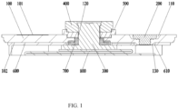
FIG. 1 is a schematic cross-sectional view of a cover plate assembly according to one or more embodiments of the present application. -
FIG. 2 is a schematic cross-sectional view of a sealing member of a cover plate assembly according to one or more embodiments of the present application. -
FIG. 3 is a schematic cross-sectional view of a cover plate of a cover plate assembly according to one or more embodiments of the present application. - As shown in
FIG. 1 to FIG. 3 , a cover plate assembly according to one or more embodiments of the present application includes acover plate 100 and asealing member 200. Thecover plate 100 is provided with a first throughhole 110, and the sealingmember 200 is arranged in the first throughhole 110. The first throughhole 110 is configured as an injection hole and an explosion-proof valve hole. - Along a direction perpendicular to the
cover plate 100, thesealing member 200 has afirst end face 2001 and asecond end face 2002 opposite to each other, thesealing member 200 is provided with afirst groove 210 extending from thesecond end face 2002 to thefirst end face 2001, an outer sidewall of thesealing member 200 close to thesecond end face 2002 is provided with afirst protrusion 220 extending in a direction parallel to thecover plate 100, thefirst protrusion 220 protrudes from a surface of thecover plate 100, and a distance between an edge of thefirst protrusion 220 and an axis of the first throughhole 110 is greater than a radius of the first through hole110. Thefirst protrusion 220 is used to fix the sealingmember 200 to thecover plate 100. - In one or more embodiments of the present application, the first through
hole 110 is connected to the interior of the battery for injection of electrolyte into the battery, and the first throughhole 110 is also used to discharge gas generated inside the battery to avoid the explosion of the battery. - Specifically, when the
cover plate 100 is assembled with a housing of the battery, the opening side of thefirst groove 210 faces the inside of the housing during assembly, and the electrolyte is injected into the housing through the first throughhole 110. After the injection is completed, the sealingmember 200 is inserted into the first throughhole 110 to seal the first throughhole 110. When a large amount of gas is produced in the housing, a certain pressure of gas acts in thefirst groove 210 and produces a force perpendicular to thecover plate 100 on thefirst groove 210, making thefirst protrusion 220 move in the radial direction toward the center of the first throughhole 110. That is, the two ends of theseal member 200 located in thesecond end face 2002 shrink to the center of thefirst groove 210, and after thefirst protrusion 220 shrank into the first throughhole 110, theseal member 200 is lifted by the gas in the housing and protrudes outside the first throughhole 110, so that the gas in the housing is discharged from the battery through the first throughhole 110, thereby achieving the purpose of exhaust and explosion-proof. - The cross-section shape of the
first protrusion 220 can be a triangle, but is not limited thereto. For example, a right triangle, one right-angled side of thefirst protrusion 220 is in contact with the outer sidewall of thesealing member 200, and the other right-angled side of thefirst protrusion 220 is in contact with the surface of thecover plate 100. Thefirst protrusion 220 protrudes outside the first throughhole 110, and is used to fix the sealingmember 200 to thecover plate 100. - In the above embodiments, the explosion-proof valve hole and the injection hole are integrated into one hole, and the structure of the sealing
member 200 is optimized, thereby ensuring a good sealing effect while playing an explosion-proof role, reducing production costs, and improving battery assembly efficiency. - In one or more embodiments of the present application, the cover plate assembly further includes a
post 300, aterminal 400, anupper plastic 500, alower plastic 600 and acollector plate 800. Thecover plate 100 is provided with a second throughhole 120, and thepost 300 is arranged in the second throughhole 120; theterminal 400 is arranged at an end of thepost 300 near thefirst end face 2001, and theupper plastic 500 is arranged between theterminal 400 and thecover plate 100; thecollector plate 800 is arranged at an end of thepost 300 near thesecond end face 2002, and thelower plastic 600 is arranged between thecollector plate 800 and thecover plate 100. - Specifically, as shown in
FIG. 1 ,cover plate 100 has afirst surface 101 and asecond surface 102 opposite each other, thesecond surface 102 is toward the inside of the battery, thepost 300 is an inverted T shape, the end of thepost 300 with a larger diameter is located on the side of thesecond surface 102 away from thefirst surface 101, the end of thepost 300 with a smaller diameter passes through the second throughhole 120 and protruding from thefirst surface 101. Theterminal 400 is arranged at the end of the part of thepost 300 protruding from thefirst surface 101. The upper plastic 500 is arranged between theterminal 400 and thecover plate 100, and theupper plastic 500 is provided with a through hole, and thepost 300 passes through the through hole. Theupper plastic 500 is used to insulate theterminal 400 from thecover plate 100 and improve the sealing performance. Asealing ring 700 is arranged between the outer sidewall of post 300 and the inner sidewall of the second throughhole 120, and thesealing ring 700 is used to improve the sealing performance betweenpost 300 and the second throughhole 120. Thelower plastic 600 is arranged on thesecond surface 102 of thecover plate 100. Thecollector plate 800 is arranged on the side of the end of thepost 300 with a larger diameter away from thesecond surface 102. - In one or more embodiments of the present application, as shown in
FIG. 1 , alocation hole 610 is provided on thelower plastic 600, and thelocation hole 610 is opposite to and connected with the first throughhole 110, and alocation protrusion 130 matching thelocation hole 610 is provided on one side of thecover plate 100 close to thelower plastic 600. Thelower plastic 600 is used to prevent thecollector plate 800 and thecover plate 100 from contacting and causing a short circuit, so thelower plastic 600 is located between and insulates thecollector plate 800 and thecover plate 100. Thelocation protrusion 130 on thecover plate 100 is inserted into thelocation hole 610 on thelower plastic 600 to install and position thelower plastic 600 and thecover plate 100, and at the same time, the first throughhole 110 is connected to the interior of the battery. - In one or more embodiments of the present application, as shown in
FIG. 2 to FIG. 3 , the first throughhole 110 is a stepped hole with a T shaped cross-section. The first throughhole 110 includes afirst hole 111 and asecond hole 112 arranged in a stacked manner, the diameter of thefirst hole 111 is greater than the diameter of thesecond hole 112, and astep 115 is provided between thefirst hole 111 and thesecond hole 112. - The cross-section of the sealing
member 200 is "T" shaped. The sealingmember 200 includes afixing portion 201 and asealing portion 202 connected with thefixing portion 201. The diameter of the fixingportion 201 is greater than the diameter of the sealingportion 202. The fixingportion 201 is arranged in thefirst hole 111, and the sealingportion 202 is arranged in thesecond hole 112. The diameter of the sealingportion 202 matches the inner diameter of thesecond hole 112, so that the sealing performance of the sealingmember 200 can be guaranteed when the sealingportion 202 is accommodated in thesecond hole 112. - When the first through
hole 110 is a stepped hole, the distance from the edge of thefirst protrusion 220 to the axis of thesecond hole 112 is greater than the radius of thesecond hole 112, and the distance from the edge of thefirst protrusion 220 to the axis of thesecond hole 112 is less than the radius of thefirst hole 111, so as to ensure the fixing function of thefirst protrusion 220 while avoiding thefirst protrusion 220 from occupying too much space. - In one or more embodiments of the present application, as shown in
FIG. 2 to FIG. 3 , the outer sidewall of the sealingportion 202 is provided with asecond protrusion 230, and the inner wall of thesecond hole 112 is provided with asecond groove 113 matching thesecond protrusion 230. When the sealingportion 202 is inserted into thesecond hole 112, thesecond protrusion 230 is interference-fitted with thesecond groove 113, so as to improve the sealing performance of the sealingportion 202 and improve the reliability of the connection between the sealingmember 200 and thecover plate 100. - In one or more embodiments of the present application, the
second protrusion 230 is an annular protrusion surrounding the outer sidewall of the sealingportion 202, and thesecond groove 113 is an annular through groove surrounding the inner wall of thesecond hole 112, which can further improve the sealing performance of the sealingportion 202. - In one or more other embodiments of the present application, a plurality of
second protrusions 230 may be provided on the outer sidewall of the sealingportion 202, and a plurality ofsecond grooves 113 matching thesecond protrusions 230 may be provided on the inner wall of thesecond hole 112, and the structures of thesecond protrusions 230 and thesecond grooves 113 are not limited to the annular shape. - The
second protrusion 230 may be a protrusion with a semi-circular cross-section, and thesecond groove 113 may be a groove with a semi-circular cross-section. For example, the radius of the semi-circular protrusion and the semi-circular groove may be set at 0.1-0.2 mm to facilitate assembly of theseal member 200 and thecover plate 100. - It should be noted that the cross-sections of the
second protrusion 230 and thesecond groove 113 may also be other shapes, and no specific limitation is made here. - In one or more embodiments of the present application, as shown in
FIG. 2 to FIG. 3 , athird protrusion 240 is arranged on the side of the fixingportion 201 near thesecond hole 112, and athird groove 114 matching thethird protrusion 240 is arranged on the side of thestep 115 toward thefirst hole 111. When the sealingmember 200 is assembled in the first throughhole 110, thethird protrusion 240 is inserted into thethird groove 114, so that the sealingmember 200 is fixed to thecover plate 100, and the sealingmember 200 is prevented from circumferential rotation. - A plurality of
third protrusions 240 may be provided on the fixingportion 201, and a plurality ofthird grooves 114 matching thethird protrusions 240 may be provided on thestep 115. For example, twothird protrusions 240 may be provided on the fixingportion 201, the twothird protrusions 240 are located on opposite sides of the fixingportion 201, and twothird grooves 114 matching thethird protrusions 240 are provided on thestep 115. The height of thethird protrusion 240 may be 1/2 to 2/3 of the depth of the first throughhole 110, and the depth of thethird groove 114 matches the depth of thethird protrusion 240 to ensure the location function of thethird protrusion 240. - In one or more embodiments of the present application, as shown in
FIG. 3 , thesidewall 1111 of thefirst hole 111 is an inclined face, an angle between thesidewall 1111 of thefirst hole 111 and a plane where thecover plate 100 is located is 30° to 45°. The diameter of thefirst hole 110 is greater than the diameter of thefixed part 201, so that a certain gap is reserved between thesidewall 1111 of thefirst hole 111 and the side surface of the fixingportion 201, thesidewall 1111 of thefirst hole 111 is meanwhile inclined to facilitate the use of tools to lift the sealingmember 200 from the gap, so as to facilitate the replacement or maintenance of theseal member 200, or the exhaust and pressure relief of the battery. - In one or more embodiments of the present application, as shown in
FIG. 2 , achamfer 250 is arranged at the end of the side surface of the fixingportion 201 close to thesecond hole 112, so as to facilitate the use of tools to lift the sealingmember 200. - In one or more embodiments of the present application, as shown in
FIG. 3 , along the direction perpendicular to thecover plate 100, the depth of thefirst hole 111 is less than or equal to half of the thickness of thecover plate 100, so as to facilitate the use of tools to lift the sealingmember 200 while ensuring the sealing performance and stability of the sealingmember 200. - In one or more embodiments of the present application, a battery is provided. The battery includes a housing, a cell and the cover plate assembly as described above. The interior of the housing has an accommodating cavity, and the cell is accommodated in the accommodating cavity. One end of the housing has an opening, the cover plate assembly is sealed at the opening, and the opening of the
first groove 210 is toward the cell. When a large amount of gas accumulates inside the battery, the gas with a certain pressure acts on thefirst groove 210, so that theseal member 200 is lifted from the first throughhole 110 to achieve explosion-proof and pressure relief. At the same time, the first throughhole 110 also serves as an injection hole, and the electrolyte is injected into the housing from the first throughhole 110. - The housing may be a cylindrical housing, and the battery may be a cylindrical battery, but is not limited thereto.
- In one or more embodiments of the present application, a battery pack is provided. The battery pack includes a battery case and at least one battery as described above, and the battery is arranged in the battery case.
- In the above embodiments, a cover plate assembly, a battery and a battery pack are provided. By setting a first through hole on the cover plate, the first through hole is used as an injection hole and an explosion-proof hole. After injecting electrolyte into the first through hole, the first through hole is sealed with a sealing member. When a large amount of gas is generated inside the battery, a certain pressure of gas acts on the first groove of the sealing member, so that the first protrusion moves in the radial direction toward the center of the first through hole, so that the sealing member is lifted up from the first through hole by the gas in the battery and protrudes outside the first through hole, so as to achieve the effect of exhaust explosion prevention. The explosion-proof valve hole and the injection hole are integrated into one hole, and the structure of the sealing member is optimized, thereby ensuring a good sealing effect while playing an explosion-proof role, reducing production costs, and improving battery assembly efficiency.
Claims (12)
- A cover plate assembly, characterized by comprising a cover plate (100) and a sealing member (200),wherein the cover plate (100) is provided with a first through hole (110), and the sealing member (200) is disposed to pass through the first through hole (110);the sealing member (200) has a first end face (2001) and a second end face (2002) opposite to each other in a direction perpendicular to the cover plate (100);the sealing member (200) is provided with a first groove (210) extending from the second end face (2002) to the first end face (2001);an outer sidewall of the sealing member (200) close to the second end face (2002) is provided with a first protrusion (220) extending in a direction parallel to the cover plate (100) and protruding from a surface of the cover plate (100); anda distance between an edge of the first protrusion (220) and an axis of the first through hole (110) is greater than a radius of the first through hole (100).
- The cover plate assembly according to claim 1, characterized in that the first through hole (110) is a stepped hole comprising a first hole (111) and a second hole (112) that are stacked, a diameter of the first hole (111) is greater than a diameter of the second hole (112), and a step (115) is formed between the first hole (111) and the second hole (112); and
the sealing member (200) comprises a fixing portion (201) and a sealing portion (202) connected with the fixing portion (201), a diameter of the fixing portion (201) is greater than a diameter of the sealing portion (202), the fixing portion (201) is arranged in the first hole (111), and the sealing portion (202) is arranged in the second hole (112). - The cover plate assembly according to claim 2, characterized in that an outer sidewall of the sealing portion (22) is provided with a second protrusion (230), and an inner wall of the second hole (112) is provided with a second groove (113) matching the second protrusion (230).
- The cover plate assembly according to claim 3, characterized in that the second protrusion (230) is an annular protrusion surrounding the outer sidewall of the sealing portion (202), and the second groove (113) is an annular through groove surrounding the inner wall of the second hole (112).
- The cover plate assembly according to claim 2, characterized in that a side of the fixing portion (201) close to the second hole (112) is provided with a third protrusion (240), and a side of the step (115) facing the first hole (111) is provided with a third groove (114) matching the third protrusion (240).
- The cover plate assembly according to claim 2, characterized in that a sidewall of the first hole (111) is an inclined face, and an angle of 30° to 45° is formed between the sidewall of the first hole (111) and a plane where the cover plate (100) is located; and
the diameter of the first hole (111) is greater than the diameter of the fixing portion (201). - The cover plate assembly according to claim 6, characterized in that an end of a side surface of the fixing portion (201) close to the second hole (112) is provided with a chamfer (250).
- The cover plate assembly according to any one of claims 2-7, characterized in that in the direction perpendicular to the cover plate (100) a depth of the first hole (111) is less than or equal to half of a thickness of the cover plate (100).
- The cover plate assembly according to any one of claims 1-7, characterized in that the cover plate assembly further comprise a post (300), a terminal (400), an upper plastic (500), a collector plate (800) and a lower plastic (600),wherein the cover plate (100) is further provided with a second through hole (120), and the post (300) is disposed to pass through the second through hole (120);the terminal (400) is arranged at an end of the post (300) close to the first end face (2001), and the upper plastic (500) is arranged between the terminal (400) and the cover plate (100); andthe collector plate (800) is arranged at an end of the post (300) close to the second end face (2002), and the lower plastic (600) is arranged between the collector plate (800) and the cover plate (100).
- The cover plate assembly according to claim 9, characterized in that the lower plastic (600) is provided with a location hole (610) that is opposite to and connected with the first through hole (110); and
a side of the cover plate (100) close to the lower plastic (600) is provided with a location protrusion (130) matching the location hole (610). - A battery, characterized by comprising a housing, a cell and a cover plate assembly of any one of claims 1-10, wherein an accommodating cavity is provided inside the housing, and the cell is accommodated in the accommodating cavity; an end of the housing has an opening covered by the cover plate assembly; and an opening of the first groove (210) faces the cell.
- A battery pack, characterized by comprising a battery case and at least one battery of claim 11 arranged in the battery case.
Applications Claiming Priority (2)
| Application Number | Priority Date | Filing Date | Title |
|---|---|---|---|
| CN202322099003.2U CN220627988U (en) | 2023-08-04 | 2023-08-04 | Cover components, batteries and battery packs |
| PCT/CN2024/109003 WO2025031243A1 (en) | 2023-08-04 | 2024-07-31 | Cover plate assembly, battery and battery pack |
Publications (2)
| Publication Number | Publication Date |
|---|---|
| EP4557473A1 true EP4557473A1 (en) | 2025-05-21 |
| EP4557473A4 EP4557473A4 (en) | 2026-03-04 |
Family
ID=90232060
Family Applications (1)
| Application Number | Title | Priority Date | Filing Date |
|---|---|---|---|
| EP24850888.9A Pending EP4557473A4 (en) | 2023-08-04 | 2024-07-31 | Cover plate assembly, battery and battery pack |
Country Status (7)
| Country | Link |
|---|---|
| US (1) | US20250140998A1 (en) |
| EP (1) | EP4557473A4 (en) |
| JP (2) | JP2025540286A (en) |
| KR (1) | KR20250022702A (en) |
| CN (1) | CN220627988U (en) |
| DE (1) | DE212024000049U1 (en) |
| WO (1) | WO2025031243A1 (en) |
Families Citing this family (1)
| Publication number | Priority date | Publication date | Assignee | Title |
|---|---|---|---|---|
| CN220627988U (en) * | 2023-08-04 | 2024-03-19 | 湖北亿纬动力有限公司 | Cover components, batteries and battery packs |
Family Cites Families (10)
| Publication number | Priority date | Publication date | Assignee | Title |
|---|---|---|---|---|
| DE6933117U (en) * | 1969-08-21 | 1970-01-22 | Illinois Tool Works | HOLE PLUG |
| GB2067253A (en) * | 1980-01-11 | 1981-07-22 | United Carr Ltd | Aperture plug |
| JPS6229400Y2 (en) * | 1980-05-21 | 1987-07-28 | ||
| CN201436694U (en) * | 2009-06-24 | 2010-04-07 | 东莞新能源科技有限公司 | Power battery liquid injection and explosion-proof device |
| JP5498890B2 (en) * | 2009-11-12 | 2014-05-21 | 株式会社ニフコ | Automotive plugs |
| JP6241676B2 (en) * | 2015-03-27 | 2017-12-06 | トヨタ自動車株式会社 | Sealed battery |
| CN209472005U (en) * | 2019-01-17 | 2019-10-08 | 天津银隆新能源有限公司 | A battery top cover liquid injection explosion-proof structure and battery |
| CN210136896U (en) * | 2019-07-04 | 2020-03-10 | 湖北金泉新材料有限责任公司 | Top cover explosion-proof structure and battery containing the same |
| KR20220170620A (en) * | 2021-06-23 | 2022-12-30 | 주식회사 니프코코리아 | Hole Plug for Vehicles |
| CN220627988U (en) * | 2023-08-04 | 2024-03-19 | 湖北亿纬动力有限公司 | Cover components, batteries and battery packs |
-
2023
- 2023-08-04 CN CN202322099003.2U patent/CN220627988U/en active Active
-
2024
- 2024-07-31 DE DE212024000049.3U patent/DE212024000049U1/en active Active
- 2024-07-31 EP EP24850888.9A patent/EP4557473A4/en active Pending
- 2024-07-31 KR KR1020247042228A patent/KR20250022702A/en active Pending
- 2024-07-31 WO PCT/CN2024/109003 patent/WO2025031243A1/en not_active Ceased
- 2024-07-31 JP JP2025533273A patent/JP2025540286A/en active Pending
- 2024-12-29 US US19/004,400 patent/US20250140998A1/en active Pending
-
2025
- 2025-07-30 JP JP2025002578U patent/JP3253752U/en active Active
Also Published As
| Publication number | Publication date |
|---|---|
| US20250140998A1 (en) | 2025-05-01 |
| EP4557473A4 (en) | 2026-03-04 |
| JP2025540286A (en) | 2025-12-11 |
| KR20250022702A (en) | 2025-02-17 |
| WO2025031243A1 (en) | 2025-02-13 |
| DE212024000049U1 (en) | 2025-01-23 |
| JP3253752U (en) | 2025-11-25 |
| CN220627988U (en) | 2024-03-19 |
Similar Documents
| Publication | Publication Date | Title |
|---|---|---|
| US20230253649A1 (en) | Cap assembly of battery, cylindrical battery, and battery pack | |
| CN210379128U (en) | Button Battery | |
| EP4167339B1 (en) | Top cover assembly for battery and battery | |
| US20230299447A1 (en) | Electrochemical apparatus and electronic device | |
| US20240162536A1 (en) | Battery top cover assembly | |
| WO2018225609A1 (en) | Battery module | |
| WO2022152170A1 (en) | Lower plastic member for battery cell, battery cell, and battery module | |
| US20250140998A1 (en) | Cover plate assembly, battery and battery pack | |
| US20240128560A1 (en) | Power battery top cover structure | |
| CN219937299U (en) | Battery case and battery | |
| US20260045625A1 (en) | Battery | |
| CN116544571B (en) | Top cover components, energy storage devices and electrical equipment | |
| CN220492123U (en) | Explosion-proof valve, top cap subassembly and battery | |
| JP7655993B2 (en) | Cylindrical battery and electronic device | |
| CN116111245A (en) | End cover assembly, energy storage device and electrical equipment | |
| CN116845445A (en) | Batteries and battery packs | |
| KR100281461B1 (en) | Safety valve device for lithium ion battery | |
| CN116706362B (en) | Battery cover plate and battery | |
| CN221766987U (en) | Seals, cover assemblies and batteries | |
| CN119786839B (en) | End cover assembly, energy storage device and electrical equipment | |
| CN223502031U (en) | End cap assemblies, energy storage devices and electrical equipment | |
| CN222867821U (en) | Top cover assembly and battery | |
| CN223712897U (en) | A top cover structure and a single battery cell | |
| CN221352962U (en) | Battery top cover assembly and battery | |
| CN220358266U (en) | Explosion-proof cover plate of battery and battery |
Legal Events
| Date | Code | Title | Description |
|---|---|---|---|
| STAA | Information on the status of an ep patent application or granted ep patent |
Free format text: STATUS: THE INTERNATIONAL PUBLICATION HAS BEEN MADE |
|
| PUAI | Public reference made under article 153(3) epc to a published international application that has entered the european phase |
Free format text: ORIGINAL CODE: 0009012 |
|
| STAA | Information on the status of an ep patent application or granted ep patent |
Free format text: STATUS: REQUEST FOR EXAMINATION WAS MADE |
|
| 17P | Request for examination filed |
Effective date: 20250217 |
|
| AK | Designated contracting states |
Kind code of ref document: A1 Designated state(s): AL AT BE BG CH CY CZ DE DK EE ES FI FR GB GR HR HU IE IS IT LI LT LU LV MC ME MK MT NL NO PL PT RO RS SE SI SK SM TR |
|
| A4 | Supplementary search report drawn up and despatched |
Effective date: 20260129 |
|
| RIC1 | Information provided on ipc code assigned before grant |
Ipc: H01M 50/186 20210101AFI20260123BHEP Ipc: B62D 25/24 20060101ALI20260123BHEP Ipc: H01M 50/147 20210101ALI20260123BHEP Ipc: H01M 50/172 20210101ALI20260123BHEP Ipc: H01M 50/184 20210101ALI20260123BHEP Ipc: H01M 50/308 20210101ALI20260123BHEP Ipc: H01M 50/655 20210101ALI20260123BHEP |