EP4557460A1 - Liquid cooling assembly and battery pack - Google Patents
Liquid cooling assembly and battery pack Download PDFInfo
- Publication number
- EP4557460A1 EP4557460A1 EP24852927.3A EP24852927A EP4557460A1 EP 4557460 A1 EP4557460 A1 EP 4557460A1 EP 24852927 A EP24852927 A EP 24852927A EP 4557460 A1 EP4557460 A1 EP 4557460A1
- Authority
- EP
- European Patent Office
- Prior art keywords
- liquid
- liquid cooling
- mating
- straight pipe
- joint
- Prior art date
- Legal status (The legal status is an assumption and is not a legal conclusion. Google has not performed a legal analysis and makes no representation as to the accuracy of the status listed.)
- Granted
Links
Images


Classifications
-
- H—ELECTRICITY
- H01—ELECTRIC ELEMENTS
- H01M—PROCESSES OR MEANS, e.g. BATTERIES, FOR THE DIRECT CONVERSION OF CHEMICAL ENERGY INTO ELECTRICAL ENERGY
- H01M10/00—Secondary cells; Manufacture thereof
- H01M10/60—Heating or cooling; Temperature control
- H01M10/65—Means for temperature control structurally associated with the cells
- H01M10/655—Solid structures for heat exchange or heat conduction
- H01M10/6556—Solid parts with flow channel passages or pipes for heat exchange
- H01M10/6557—Solid parts with flow channel passages or pipes for heat exchange arranged between the cells
-
- F—MECHANICAL ENGINEERING; LIGHTING; HEATING; WEAPONS; BLASTING
- F28—HEAT EXCHANGE IN GENERAL
- F28F—DETAILS OF HEAT-EXCHANGE AND HEAT-TRANSFER APPARATUS, OF GENERAL APPLICATION
- F28F9/00—Casings; Header boxes; Auxiliary supports for elements; Auxiliary members within casings
- F28F9/02—Header boxes; End plates
- F28F9/04—Arrangements for sealing elements into header boxes or end plates
- F28F9/06—Arrangements for sealing elements into header boxes or end plates by dismountable joints
-
- F—MECHANICAL ENGINEERING; LIGHTING; HEATING; WEAPONS; BLASTING
- F28—HEAT EXCHANGE IN GENERAL
- F28F—DETAILS OF HEAT-EXCHANGE AND HEAT-TRANSFER APPARATUS, OF GENERAL APPLICATION
- F28F9/00—Casings; Header boxes; Auxiliary supports for elements; Auxiliary members within casings
- F28F9/26—Arrangements for connecting different sections of heat-exchange elements, e.g. of radiators
-
- H—ELECTRICITY
- H01—ELECTRIC ELEMENTS
- H01M—PROCESSES OR MEANS, e.g. BATTERIES, FOR THE DIRECT CONVERSION OF CHEMICAL ENERGY INTO ELECTRICAL ENERGY
- H01M10/00—Secondary cells; Manufacture thereof
- H01M10/60—Heating or cooling; Temperature control
- H01M10/61—Types of temperature control
- H01M10/613—Cooling or keeping cold
-
- H—ELECTRICITY
- H01—ELECTRIC ELEMENTS
- H01M—PROCESSES OR MEANS, e.g. BATTERIES, FOR THE DIRECT CONVERSION OF CHEMICAL ENERGY INTO ELECTRICAL ENERGY
- H01M10/00—Secondary cells; Manufacture thereof
- H01M10/60—Heating or cooling; Temperature control
- H01M10/62—Heating or cooling; Temperature control specially adapted for specific applications
- H01M10/625—Vehicles
-
- H—ELECTRICITY
- H01—ELECTRIC ELEMENTS
- H01M—PROCESSES OR MEANS, e.g. BATTERIES, FOR THE DIRECT CONVERSION OF CHEMICAL ENERGY INTO ELECTRICAL ENERGY
- H01M10/00—Secondary cells; Manufacture thereof
- H01M10/60—Heating or cooling; Temperature control
- H01M10/64—Heating or cooling; Temperature control characterised by the shape of the cells
- H01M10/643—Cylindrical cells
-
- H—ELECTRICITY
- H01—ELECTRIC ELEMENTS
- H01M—PROCESSES OR MEANS, e.g. BATTERIES, FOR THE DIRECT CONVERSION OF CHEMICAL ENERGY INTO ELECTRICAL ENERGY
- H01M10/00—Secondary cells; Manufacture thereof
- H01M10/60—Heating or cooling; Temperature control
- H01M10/65—Means for temperature control structurally associated with the cells
- H01M10/655—Solid structures for heat exchange or heat conduction
- H01M10/6556—Solid parts with flow channel passages or pipes for heat exchange
-
- H—ELECTRICITY
- H01—ELECTRIC ELEMENTS
- H01M—PROCESSES OR MEANS, e.g. BATTERIES, FOR THE DIRECT CONVERSION OF CHEMICAL ENERGY INTO ELECTRICAL ENERGY
- H01M10/00—Secondary cells; Manufacture thereof
- H01M10/60—Heating or cooling; Temperature control
- H01M10/65—Means for temperature control structurally associated with the cells
- H01M10/656—Means for temperature control structurally associated with the cells characterised by the type of heat-exchange fluid
- H01M10/6567—Liquids
-
- H—ELECTRICITY
- H01—ELECTRIC ELEMENTS
- H01M—PROCESSES OR MEANS, e.g. BATTERIES, FOR THE DIRECT CONVERSION OF CHEMICAL ENERGY INTO ELECTRICAL ENERGY
- H01M10/00—Secondary cells; Manufacture thereof
- H01M10/60—Heating or cooling; Temperature control
- H01M10/65—Means for temperature control structurally associated with the cells
- H01M10/656—Means for temperature control structurally associated with the cells characterised by the type of heat-exchange fluid
- H01M10/6567—Liquids
- H01M10/6568—Liquids characterised by flow circuits, e.g. loops, located externally to the cells or cell casings
-
- H—ELECTRICITY
- H01—ELECTRIC ELEMENTS
- H01M—PROCESSES OR MEANS, e.g. BATTERIES, FOR THE DIRECT CONVERSION OF CHEMICAL ENERGY INTO ELECTRICAL ENERGY
- H01M50/00—Constructional details or processes of manufacture of the non-active parts of electrochemical cells other than fuel cells, e.g. hybrid cells
- H01M50/20—Mountings; Secondary casings or frames; Racks, modules or packs; Suspension devices; Shock absorbers; Transport or carrying devices; Holders
- H01M50/204—Racks, modules or packs for multiple batteries or multiple cells
- H01M50/207—Racks, modules or packs for multiple batteries or multiple cells characterised by their shape
- H01M50/213—Racks, modules or packs for multiple batteries or multiple cells characterised by their shape adapted for cells having curved cross-section, e.g. round or elliptic
-
- F—MECHANICAL ENGINEERING; LIGHTING; HEATING; WEAPONS; BLASTING
- F28—HEAT EXCHANGE IN GENERAL
- F28F—DETAILS OF HEAT-EXCHANGE AND HEAT-TRANSFER APPARATUS, OF GENERAL APPLICATION
- F28F1/00—Tubular elements; Assemblies of tubular elements
- F28F1/02—Tubular elements of cross-section which is non-circular
- F28F1/022—Tubular elements of cross-section which is non-circular with multiple channels
-
- F—MECHANICAL ENGINEERING; LIGHTING; HEATING; WEAPONS; BLASTING
- F28—HEAT EXCHANGE IN GENERAL
- F28F—DETAILS OF HEAT-EXCHANGE AND HEAT-TRANSFER APPARATUS, OF GENERAL APPLICATION
- F28F1/00—Tubular elements; Assemblies of tubular elements
- F28F1/02—Tubular elements of cross-section which is non-circular
- F28F1/025—Tubular elements of cross-section which is non-circular with variable shape, e.g. with modified tube ends, with different geometrical features
-
- F—MECHANICAL ENGINEERING; LIGHTING; HEATING; WEAPONS; BLASTING
- F28—HEAT EXCHANGE IN GENERAL
- F28F—DETAILS OF HEAT-EXCHANGE AND HEAT-TRANSFER APPARATUS, OF GENERAL APPLICATION
- F28F1/00—Tubular elements; Assemblies of tubular elements
- F28F1/08—Tubular elements crimped or corrugated in longitudinal section
-
- F—MECHANICAL ENGINEERING; LIGHTING; HEATING; WEAPONS; BLASTING
- F28—HEAT EXCHANGE IN GENERAL
- F28F—DETAILS OF HEAT-EXCHANGE AND HEAT-TRANSFER APPARATUS, OF GENERAL APPLICATION
- F28F2265/00—Safety or protection arrangements; Arrangements for preventing malfunction
- F28F2265/26—Safety or protection arrangements; Arrangements for preventing malfunction for allowing differential expansion between elements
-
- Y—GENERAL TAGGING OF NEW TECHNOLOGICAL DEVELOPMENTS; GENERAL TAGGING OF CROSS-SECTIONAL TECHNOLOGIES SPANNING OVER SEVERAL SECTIONS OF THE IPC; TECHNICAL SUBJECTS COVERED BY FORMER USPC CROSS-REFERENCE ART COLLECTIONS [XRACs] AND DIGESTS
- Y02—TECHNOLOGIES OR APPLICATIONS FOR MITIGATION OR ADAPTATION AGAINST CLIMATE CHANGE
- Y02E—REDUCTION OF GREENHOUSE GAS [GHG] EMISSIONS, RELATED TO ENERGY GENERATION, TRANSMISSION OR DISTRIBUTION
- Y02E60/00—Enabling technologies; Technologies with a potential or indirect contribution to GHG emissions mitigation
- Y02E60/10—Energy storage using batteries
Definitions
- the present application relates to the field of battery technologies, and in particular to a liquid cooling assembly and a battery pack.
- liquid cooling plates are widely used in batteries, and the main function of the liquid cooling plates is to cool the battery through the circulation of coolant, thereby maintaining the stability of the battery temperature.
- Liquid cooling plates are usually connected to the liquid inlet pipe with the nylon tubes.
- the present application provides a liquid cooling assembly, including: a plurality of liquid cooling plates, in which the plurality of liquid cooling plates are arranged in sequence at intervals, an installation space for installing a heating element is formed between adjacent ones of the plurality of liquid cooling plates, and the plurality of liquid cooling plates include circulation channels, and liquid inlets each communicating with a corresponding one of the circulation channels; and a liquid inlet main pipe, in which the liquid inlet main pipe includes a plurality of first mating ports, and the plurality of first mating ports and the liquid inlets are arranged by one-to-one correspondence; in which first mating tubes are connected between the first mating ports and the liquid inlets, and each of the first mating tubes is at least partially flexible.
- the present application also provides a battery pack including the above-mentioned liquid cooling assembly.
- the first mating tube can absorb the tolerances of both the liquid inlet main pipe and the liquid cooling plate during the connection process. In this way, the assembly of the liquid inlet main pipe and the liquid cooling plate becomes simple, and the reliability of the connection between the liquid inlet main pipe and the liquid cooling plate is ensured, and leakage between the liquid inlet pipe and the liquid cooling plate is avoided, thereby avoiding the phenomenon of reducing cooling efficiency due to the leakage.
- the liquid cooling plate is connected to the liquid inlet main pipe via the first mating tube. Since the first mating tube is at least partially flexible, the tolerances of the liquid inlet main pipe and the liquid cooling plate can be absorbed during the connection process, In this way, the assembly of the liquid inlet main pipe and the liquid cooling plate becomes simple, and the reliability of the connection between the liquid inlet main pipe and the liquid cooling plate is ensured, and leakage between the liquid inlet pipe and the liquid cooling plate is avoided, thereby avoiding the phenomenon of reducing cooling efficiency due to the leakage.
- 10-liquid cooling plate 101-liquid inlet, 102-liquid return port, 11-second joint, 12-fourth joint, 20-liquid inlet main pipe, 201-first mating port, 202-total water inlet, 21-first main pipe, 211-first joint, 22-first quick-plug connector, 30-first mating tube, 31-first straight pipe section, 32-first corrugated section, 33-second straight pipe section, 40-liquid return main pipe, 401-second mating port, 402-total water return port, 41-second main pipe, 411-third joint, 42-second quick-plug connector, 50-second mating tube, 51-third straight pipe section, 52-second corrugated section, and 53-fourth straight pipe section.
- connection In the description of the present application, unless otherwise expressly specified and limited, the terms “conjoint”, “connect”, and “fix” are to be understood in a broad sense, for example, as a fixed connection, as a detachable connection, or as a one-piece connection; also as a mechanical connection or an electrical connection; or may be directly connected or indirectly connected by means of an intermediate medium; or may be internal communication of the two elements or interaction of the two elements.
- connection In the description of the present application, unless otherwise expressly specified and limited, the terms “conjoint”, “connect”, and “fix” are to be understood in a broad sense, for example, as a fixed connection, as a detachable connection, or as a one-piece connection; also as a mechanical connection or an electrical connection; or may be directly connected or indirectly connected by means of an intermediate medium; or may be internal communication of the two elements or interaction of the two elements.
- the specific meaning of the above terms in the present application may be understood by one of ordinary skill in the art as the case may
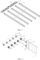
- FIG. 1 is a first perspective schematic diagram of the liquid cooling assembly provided by the embodiments of the present application
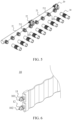
- FIG. 2 is a second perspective schematic diagram of the liquid cooling assembly provided by the embodiments of the present application.
- the liquid cooling assembly includes a plurality of liquid cooling plates 10 and a liquid inlet main pipe 20.
- the plurality of liquid cooling plates 10 are arranged in sequence and spaced apart, and an installation space for installing a heating element is formed between adjacent liquid cooling plates 10.
- Each liquid cooling plate 10 includes a circulation channel (not shown in the figure) and a liquid inlet 101 connected to the circulation channel.
- the liquid inlet main pipe 20 includes a plurality of first mating ports 201.
- the plurality of first mating ports 201 and the plurality of liquid inlets 101 are arranged by one-to-one correspondence.
- a first mating tube 30 is connected between the first mating port 201 and the liquid inlet 101, and the first mating tube 30 is at least partially flexible.
- FIG. 3 is a perspective schematic diagram of a liquid cooling assembly and a cylindrical battery provided in embodiments of the present application.
- the heating element may be a cylindrical battery
- the shape of the liquid cooling plate 10 may be a serpentine shape. This design may increase the contact area between the liquid cooling plate 10 and the cylindrical battery, thereby improving the cooling efficiency.
- the number of liquid cooling plates 10 may be 2, 3 or more.
- the liquid cooling plate 10 and the circulation channel of the liquid cooling plate are integrally formed, for example, by casting or 3D printing.
- the heating element may also be a battery that is approximately in the shape of a rectangular parallelepiped, and the shape of the liquid cooling plate 10 may also be a shape of a flat plate, so that the heating element is in full contact with the liquid cooling plate 10.
- the liquid inlet 101 may refer to an opening opened in the surface of the liquid cooling plate 10.
- a second joint 11 may be provided protruding from the surface of the liquid cooling plate 10.
- a through hole of the joint defines the liquid inlet 101, so as to facilitate to connect the first mating tube 30 through the second joint 11.
- the number of the first mating ports 201 may be 2, or 3 or more.
- the first mating port 201 may refer to an opening opened in the surface of the liquid inlet main pipe 20.
- a joint may be provided protruding from the surface of the liquid inlet main pipe 20, and a through hole of the joint defines the first mating port 201, so as to facilitate connect the first mating tube 30 through the joint.
- the liquid inlet main pipe 20 may be composed of a whole pipe. In some other embodiments of the present application, the liquid inlet main pipe 20 may be composed of multiple pipes connected in series, so as to facilitate replacement when one pipe is damaged.
- a first mating tube 30 is connected between the first mating port 201 of the liquid inlet main pipe 20 and the liquid inlet 101 of the liquid cooling plate 10, and the first mating tube 30 is at least partially flexible. Since the first mating tube 30 is at least partially flexible, that is, the first mating tube 30 has elasticity and scalability, the first mating tube 30 can absorb the tolerances of both the liquid inlet main pipe 20 and the liquid cooling plate 10 during the connection.
- the assembly of the liquid inlet main pipe 20 and the liquid cooling plate 10 becomes simple, and the reliability of the connection between the liquid inlet main pipe 20 and the liquid cooling plate 10 is ensured, and leakage between the liquid inlet main pipe 20 and the liquid cooling plate 10 is avoided, thereby avoiding the phenomenon that the cooling efficiency is reduced due to the leakage.
- the first mating tube 30 may be a flexible and bent pipe such as a hose or a corrugated tube.
- the liquid inlet 101 and the liquid return port 102 of the liquid cooling plate 10 are arranged at the same end, and the circulation channel can be arranged in a U-shape, which has better temperature uniformity.
- FIG. 1 and FIG. 3 are only schematic illustrations of the liquid inlet 101 and the liquid return port 102.
- the liquid return port 102 can be arranged at the end of the liquid cooling plate 10 facing away from the liquid inlet 101.
- the circulation channel can be arranged in a straight line or a curve.
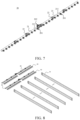
- FIG. 4 is a perspective schematic diagram of a first mating tube 30 provided in an embodiment of the present application
- FIG. 5 is a perspective schematic diagram of a first mating tube 30 and a liquid inlet main pipe 20 provided in an embodiment of the present application
- FIG. 6 is a perspective schematic diagram of a liquid cooling plate 10 provided in an embodiment of the present application.
- the first mating tube 30 has a first straight pipe section 31, a first corrugated section 32, and a second straight pipe section 33.
- the first corrugated section 32 is located between the first straight pipe section 31 and the second straight pipe section 33.
- the first straight pipe section 31 is connected to the first mating port 201
- the second straight pipe section 33 is connected to the liquid inlet 101
- the first corrugated section 32 is flexible.
- the first corrugated section 32 is a corrugated tube. Since the corrugated tube has elasticity and scalability, the tolerances of both the liquid inlet main pipe 20 and the liquid cooling plate 10 can be absorbed during the connection, thereby simplifying the assembly of the liquid inlet main pipe 20 and the liquid cooling plate 10.
- the first straight pipe section 31 and the second straight pipe section 33 are both straight pipes.
- a pore size of the first straight pipe section 31 matches a pore size of the first mating port 201.
- a pore size of the second straight pipe section 33 matches a pore size of the liquid inlet 101. So, the first straight pipe section 31 is tightly connected to the first mating port 201, and the second straight pipe section 33 is tightly connected to the liquid inlet 101, thereby ensuring that the coolant does not leak, and further improving the cooling efficiency.
- the liquid inlet main pipe 20 has a plurality of first joints 211, and the first joint 211 define the first mating port 201.
- the liquid cooling plate 10 has a second joint 11 defining a liquid inlet port 101.
- the first straight pipe section 31 is sleeved with the first joint 211, and the second straight pipe section 33 is sleeved with the second joint 11.
- the first joint 211 and the second joint 11 can improve the strength of the first mating tube 30.
- the first straight pipe section 31 can be sleeved on the first joint 211
- the second straight pipe section 33 can be sleeved on the second joint 11.
- first joint 211 can be sleeved on the first straight pipe section 31, and the second joint 11 can be sleeved on the second straight pipe section 33.
- first joint 211 and the second joint 11 are both bamboo joints.
- the first joint 211 can improve the strength of the first straight pipe section 31, and the second joint 11 can improve the strength of the second straight pipe section 33.
- the first straight pipe section 31 is expanded with the first joint 211
- the second straight pipe section 33 is expanded with the second joint 11, so as to prevent the first straight pipe section 31 and the second straight pipe section 33 from falling off.
- an end of the first straight pipe section 31 is inserted into a hole of the first joint 211.
- the end of the first straight pipe section 31 is expanded by a pipe expander, and the first straight pipe section 31 and the first joint 211 are tightly connected by utilizing the plastic deformation of the first straight pipe section 31 and the elastic deformation of the hole of the first joint 211.
- an end of the first joint 211 is inserted into a hole of the first straight pipe section 31.
- the end of the first joint 211 is expanded by a pipe expander, and the first straight pipe section 31 and the first joint 211 are tightly connected by utilizing the plastic deformation of the first joint 211 and the elastic deformation of the hole of the first straight pipe section 31.
- an end of the second straight pipe section 33 is inserted into a hole of the second joint 11.
- the end of the second straight pipe section 33 is expanded by a pipe expander, and the second straight pipe section 33 and the second joint 11 are tightly connected by using the plastic deformation of the second straight pipe section 33 and the elastic deformation of the hole of the second joint 11.
- an end of the second joint 11 is inserted into a hole of the second straight pipe section 33.
- the end of the second joint 11 is expanded by a pipe expander, and the second straight pipe section 33 and the second joint 11 are tightly connected by using the plastic deformation of the second joint 11 and the elastic deformation of the hole of the second straight pipe section 33.
- first joint 211 and the second joint 11 may also be connected to the first mating tube 30 in other ways, such as welding or threaded connection.
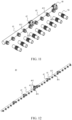
- FIG. 7 is a perspective schematic diagram of a liquid inlet main pipe 20 provided in an embodiment of the present application.
- the liquid inlet main pipe 20 includes a plurality of first main pipes 21 that are separately arranged, and the plurality of first main pipes 21 are connected in sequence. At least some of the first main pipes 21 have first mating ports 201.
- the first main pipe 21 is arranged with a plurality of first joints 211, and the first joints 211 are integrally formed with the first main pipe 21.
- the number of the first main pipes 21 may be 1, 2, 3 or more than 3.
- Each first main pipe 21 may be provided with one, two, three or more than three first joints 211.
- the first joints 211 are integrally formed with the first main pipe 21, for example, by casting or 3D printing, etc., which can reduce the cost of the liquid cooling assembly and improve the structural strength of the liquid inlet main pipe 20.
- a first quick-plug connector 22 is provided between adjacent first main pipes 21, and the first quick-plug connector 22 is enabled to communicate the adjacent first main pipes 21. Since the first quick-plug connector 22 can be quickly connected and disconnected, the number of first main pipes 21 can be flexibly set according to actual needs, thereby reducing the waste of the first main pipes 21 and improving the use efficiency.
- the material of the first quick-plug connector 22 can be plastic, such as PA66 GF30.
- the first quick-plug connector 22 can be of a finished pipe connection structure, such as a pipe hoop, a quick connector, etc.
- the liquid inlet main pipe 20 has a total water inlet 202.
- inner diameters of the plurality of first joints 211 gradually increase, so that the flow rate of each first joint 211 flowing into the liquid cooling plate 10 can be equal to each other.
- FIG. 8 is a third perspective schematic diagram of the liquid cooling assembly provided by the embodiment of the present application
- FIG. 9 is a fourth perspective schematic diagram of the liquid cooling assembly provided by the embodiment of the present application.
- the liquid cooling assembly further includes a liquid return pipe 40.
- Each liquid cooling plate 10 is in communication with the liquid return port 102 of the circulation channel.
- the liquid return pipe 40 has a plurality of second mating ports 401.
- the plurality of second mating ports 401 and the plurality of liquid return ports 102 are arranged by one-to-one correspondence.
- a second mating tube 50 is connected between the second mating port 401 and the liquid return port 102, and the second mating tube 50 is at least partially flexible.
- the number of the second mating ports 401 in the some embodiments of the present application may be 2, 3 or more.
- the second mating port 401 may refer to an opening opened in the surface of the liquid return main pipe 40.
- a joint may be provided protruding from the surface of the liquid return main pipe 40, and a through hole of the joint defines the second mating port 401, so as to facilitate to connect with the second mating tube 50 through the joint.
- the liquid return main pipe 40 may be composed of a whole pipe. In some other embodiments of the present application, the liquid return main pipe 40 may be composed of a plurality of pipes connected in series, so as to facilitate replacement when one pipe is damaged.
- the second mating tube 50 is connected between the second mating port 401 of the liquid return main pipe 40 and the liquid return port 102 of the liquid cooling plate 10, and the second mating tube 50 is at least partially flexible. Since the second mating tube 50 is at least partially flexible, that is, the second mating tube 50 has elasticity and scalability, the second mating tube 50 can absorb the tolerances of both the liquid return main pipe 40 and the liquid cooling plate 10 during the connection, thereby simplifying the assembly of the liquid return main pipe 40 and the liquid cooling plate 10. So, it can ensure the reliability of the connection between the liquid return main pipe 40 and the liquid cooling plate 10, thereby avoiding leakage between the liquid return main pipe 40 and the liquid cooling plate 10, and further avoiding the phenomenon of reducing the cooling efficiency due to leakage.
- the second mating tube 50 may be a flexible and bent pipe such as a hose or a corrugated pipe.
- FIG. 10 is a perspective schematic diagram of the liquid return main pipe 40 provided in the embodiment of the present application
- FIG. 11 is a perspective schematic diagram of the second mating tube 50 and the liquid return main pipe 40 provided in the embodiment of the present application.
- the second mating tube 50 has a third straight pipe section 51, a second corrugated section 52 and a fourth straight pipe section 53.
- the second corrugated section 52 is located between the third straight pipe section 51 and the fourth straight pipe section 53.
- the third straight pipe section 51 is connected to the second mating port 401
- the fourth straight pipe section 53 is connected to the liquid return port 102
- the second corrugated section 52 is flexible.
- the second corrugated section 52 is a corrugated pipe. Because the corrugated pipe has elasticity and flexibility, the second corrugated section 52 can absorb the tolerances of both the liquid return main pipe 40 and the liquid cooling plate 10 during the connection process, thereby simplifying the assembly of the liquid return main pipe 40 and the liquid cooling plate 10.
- the third straight pipe section 51 and the fourth straight pipe section 53 are both straight pipes.
- a pore size of the third straight pipe section 51 matches a pore size of the second mating port 401.
- a pore size of the fourth straight pipe section 53 matches a pore size of the liquid return port 102. In this way, the third straight pipe section 51 is tightly connected to the second mating port 401, and the fourth straight pipe section 53 is tightly connected to the liquid return port 102, thereby ensuring that the coolant does not leak, and further improving the cooling efficiency.
- the liquid return main pipe 40 has a plurality of third joints 411, and the third joint 411 define a second mating port 401.
- the liquid cooling plate 10 has a fourth joint 12 defining a liquid return port 102.
- the third straight pipe section 51 is sleeved with the third joint 411, and the fourth straight pipe section 53 is sleeved with the fourth joint 12.
- the third joint 411 and the fourth joint 12 can improve the strength of the second mating tube 50.
- the third straight pipe section 51 can be sleeved on the third joint 411
- the fourth straight pipe section 53 can be sleeved on the fourth joint 12.
- the third joint 411 can be sleeved on the third straight pipe section 51, and the fourth joint 12 can be sleeved on the fourth straight pipe section 53.
- the third joint 411 and the fourth joint 12 are both bamboo joints, the third joint 411 can improve the strength of the third straight pipe section 51, and the fourth joint 12 can improve the strength of the fourth straight pipe section 53.
- the third straight pipe section 51 is expanded with the third joint 411
- the fourth straight pipe section 53 is expanded with the fourth joint 12, so as to prevent the third straight pipe section 51 and the fourth straight pipe section 53 from falling off.
- an end of the third straight pipe section 51 is inserted into a hole of the third joint 411.
- the end of the third straight pipe section 51 is expanded by a pipe expander, and the third straight pipe section 51 and the third joint 411 are tightly connected by using the plastic deformation of the third straight pipe section 51 and the elastic deformation of the hole of the third joint 411.
- an end of the third joint 411 is inserted into a hole of the third straight pipe section 51.
- the end of the third joint 411 is expanded by a pipe expander, and the third straight pipe section 51 and the third joint 411 are tightly connected by using the plastic deformation of the third joint 411 and the elastic deformation of the hole of the third straight pipe section 51.
- an end of the fourth straight pipe section 53 is inserted into a hole of the fourth joint 12.
- the end of the fourth straight pipe section 53 is expanded by a pipe expander, and the fourth straight pipe section 53 and the fourth joint 12 are tightly connected by utilizing the plastic deformation of the fourth straight pipe section 53 and the elastic deformation of the hole of the fourth joint 12.
- an end of the fourth joint 12 is inserted into a hole of the fourth straight pipe section 53.
- the end of the fourth joint 12 is expanded by a pipe expander, and the fourth straight pipe section 53 and the fourth joint 12 are tightly connected by utilizing the plastic deformation of the fourth joint 12 and the elastic deformation of the hole of the fourth straight pipe section 53 .
- third joint 411 and the fourth joint 12 may also be connected to the second mating tube 50 in other ways, such as welding or threaded connection.
- FIG. 12 is a perspective schematic diagram of a liquid return main pipe provided in an embodiment of the present application.
- the liquid return main pipe 40 includes a plurality of second main pipes 41, and the plurality of second main pipes 41 are connected in sequence.
- the second main pipes 41 are disposed separately, and the second main pipe 41 has a second mating port 401.
- the second main pipe 41 is arranged with a plurality of third joints 411, and the third joints 411 are integrally formed with the second main pipe 41.
- the number of the second main pipes 41 may be 1, 2, 3 or more than 3.
- Each second main pipe 41 may be provided with one, two, three or more than three third joints 411.
- the third joints 411 are integrally formed with the second main pipe 41, for example, by casting or 3D printing, etc., which can reduce the cost of the liquid cooling assembly and improve the structural strength of the liquid return main pipe 40.
- a second quick-plug connector 42 is provided between adjacent second main pipes 41.
- the second quick-plug connector 42 is enabled to communicate with the adjacent second main pipes 41.
- the adjacent second main pipes 41 can be quickly connected and disconnected by the second quick-plug connector 42. So, the number of second main pipes 41 can be flexibly set according to actual needs, thereby reducing the waste of the second main pipes 41 and improving the use efficiency.
- the material of the second quick-plug connector 42 can be plastic, such as PA66 GF30.
- the second quick-plug connector 42 can be of a finished pipe connection structure, such as a pipe hoop, a quick connector, etc.
- the liquid return main pipe 40 has a total water return port 402. Along a direction away from the total water return port 402, inner diameters of the plurality of third joints 411 gradually increase, so that the flow rate of each third joint 411 out of the liquid cooling plate 10 can be equal to each other.
- the liquid inlet 101 and the liquid return port 102 are arranged at the same end of the liquid cooling plate 10, and the liquid inlet main pipe 20 and the liquid return main pipe 40 are located at the same ends of the liquid cooling plates 10, which can save space and costs.
- the liquid return port 102 can be arranged on an upper side of the liquid cooling plate 10, and the liquid inlet 101 can be arranged on a lower side of the liquid cooling plate 10.
- the liquid return port 102 can be arranged on the lower side of the liquid cooling plate 10, and the liquid inlet 101 can be arranged on the upper side of the liquid cooling plate 10.
- the present application also provides a battery pack.
- the battery pack includes the liquid cooling assembly as in the above embodiments.
- the liquid inlet main pipe is connected to the liquid cooling plate through the first mating tube. Since the first mating tube is at least partially flexible, the tolerances of both the liquid inlet pipe and the liquid cooling plate can be absorbed during the connection process, thereby making the assembly of the liquid inlet main pipe and the liquid cooling plate simple, and ensuring the reliability of the connection between the liquid inlet main pipe and the liquid cooling plate, avoiding leakage between the liquid inlet main pipe and the liquid cooling plate, and further avoiding the phenomenon of reducing cooling efficiency due to leakage.
Landscapes
- Engineering & Computer Science (AREA)
- Chemical & Material Sciences (AREA)
- Chemical Kinetics & Catalysis (AREA)
- Electrochemistry (AREA)
- General Chemical & Material Sciences (AREA)
- Manufacturing & Machinery (AREA)
- Physics & Mathematics (AREA)
- Thermal Sciences (AREA)
- Mechanical Engineering (AREA)
- General Engineering & Computer Science (AREA)
- Cooling Or The Like Of Electrical Apparatus (AREA)
- Secondary Cells (AREA)
Abstract
Description
- This application claims priority to
Chinese Patent Application No. 202322613031.1, filed with Chinese Patent Office on September 25, 2023 - The present application relates to the field of battery technologies, and in particular to a liquid cooling assembly and a battery pack.
- In the related art, liquid cooling plates are widely used in batteries, and the main function of the liquid cooling plates is to cool the battery through the circulation of coolant, thereby maintaining the stability of the battery temperature. Liquid cooling plates are usually connected to the liquid inlet pipe with the nylon tubes.
- However, due to tolerances in the connection, it is difficult to assemble the liquid inlet pipe and the liquid cooling plate, which can easily cause leakage in both the liquid inlet pipe and the liquid cooling plate, thereby reducing the cooling efficiency and ultimately causing the battery to be damaged due to the excessive temperature of the battery.
- The present application provides a liquid cooling assembly, including: a plurality of liquid cooling plates, in which the plurality of liquid cooling plates are arranged in sequence at intervals, an installation space for installing a heating element is formed between adjacent ones of the plurality of liquid cooling plates, and the plurality of liquid cooling plates include circulation channels, and liquid inlets each communicating with a corresponding one of the circulation channels; and a liquid inlet main pipe, in which the liquid inlet main pipe includes a plurality of first mating ports, and the plurality of first mating ports and the liquid inlets are arranged by one-to-one correspondence; in which first mating tubes are connected between the first mating ports and the liquid inlets, and each of the first mating tubes is at least partially flexible.
- The present application also provides a battery pack including the above-mentioned liquid cooling assembly.
- In the liquid cooling assembly provided by the present application, by setting a first mating tube between the liquid cooling plate and the liquid inlet main pipe, because the first mating tube is at least partially flexible, the first mating tube can absorb the tolerances of both the liquid inlet main pipe and the liquid cooling plate during the connection process. In this way, the assembly of the liquid inlet main pipe and the liquid cooling plate becomes simple, and the reliability of the connection between the liquid inlet main pipe and the liquid cooling plate is ensured, and leakage between the liquid inlet pipe and the liquid cooling plate is avoided, thereby avoiding the phenomenon of reducing cooling efficiency due to the leakage.
- In the battery pack provided in the present application, the liquid cooling plate is connected to the liquid inlet main pipe via the first mating tube. Since the first mating tube is at least partially flexible, the tolerances of the liquid inlet main pipe and the liquid cooling plate can be absorbed during the connection process, In this way, the assembly of the liquid inlet main pipe and the liquid cooling plate becomes simple, and the reliability of the connection between the liquid inlet main pipe and the liquid cooling plate is ensured, and leakage between the liquid inlet pipe and the liquid cooling plate is avoided, thereby avoiding the phenomenon of reducing cooling efficiency due to the leakage.
-
-
FIG. 1 is a first perspective schematic diagram of a liquid cooling assembly provided by the present application; -
FIG. 2 is a second perspective schematic diagram of a liquid cooling assembly provided by the present application; -
FIG. 3 is a perspective schematic diagram of a liquid cooling assembly and a cylindrical battery provided by the present application ; -
FIG. 4 is a perspective schematic diagram of a first mating tube provided by the present application; -
FIG. 5 is a perspective schematic diagram of first mating tubes and a liquid inlet main pipe provided by the present application; -
FIG. 6 is a perspective schematic diagram of a liquid cooling plate provided in the present application ; -
FIG. 7 is a perspective schematic diagram of a liquid inlet main pipe provided by the present application ; -
FIG. 8 is a third perspective schematic diagram of a liquid cooling assembly provided by the present application; -
FIG. 9 is a fourth perspective schematic diagram of a liquid cooling assembly provided by the present application; -
FIG. 10 is a perspective schematic diagram of a liquid return main pipe provided by the present application; -
FIG. 11 is a perspective schematic diagram of second mating tubes and a liquid return main pipe provided by the present application; and -
FIG. 12 is a perspective schematic diagram of a liquid return main pipe provided in the present application. - 10-liquid cooling plate, 101-liquid inlet, 102-liquid return port, 11-second joint, 12-fourth joint, 20-liquid inlet main pipe, 201-first mating port, 202-total water inlet, 21-first main pipe, 211-first joint, 22-first quick-plug connector, 30-first mating tube, 31-first straight pipe section, 32-first corrugated section, 33-second straight pipe section, 40-liquid return main pipe, 401-second mating port, 402-total water return port, 41-second main pipe, 411-third joint, 42-second quick-plug connector, 50-second mating tube, 51-third straight pipe section, 52-second corrugated section, and 53-fourth straight pipe section.
- In the description of the present application, unless otherwise expressly specified and limited, the terms "conjoint", "connect", and "fix" are to be understood in a broad sense, for example, as a fixed connection, as a detachable connection, or as a one-piece connection; also as a mechanical connection or an electrical connection; or may be directly connected or indirectly connected by means of an intermediate medium; or may be internal communication of the two elements or interaction of the two elements. The specific meaning of the above terms in the present application may be understood by one of ordinary skill in the art as the case may be.
- In the description of this embodiment, the terms "first" and "second" are used to distinguish in the description and have no special meanings.
- The embodiments of the present application provide a liquid cooling plate assembly.
FIG. 1 is a first perspective schematic diagram of the liquid cooling assembly provided by the embodiments of the present application, andFIG. 2 is a second perspective schematic diagram of the liquid cooling assembly provided by the embodiments of the present application. Referring toFIG. 1 and FIG. 2 , the liquid cooling assembly includes a plurality ofliquid cooling plates 10 and a liquid inletmain pipe 20. The plurality ofliquid cooling plates 10 are arranged in sequence and spaced apart, and an installation space for installing a heating element is formed between adjacentliquid cooling plates 10. Eachliquid cooling plate 10 includes a circulation channel (not shown in the figure) and aliquid inlet 101 connected to the circulation channel. The liquid inletmain pipe 20 includes a plurality offirst mating ports 201. The plurality offirst mating ports 201 and the plurality ofliquid inlets 101 are arranged by one-to-one correspondence. Afirst mating tube 30 is connected between thefirst mating port 201 and theliquid inlet 101, and thefirst mating tube 30 is at least partially flexible. - In some embodiments of the present application,
FIG. 3 is a perspective schematic diagram of a liquid cooling assembly and a cylindrical battery provided in embodiments of the present application. Referring toFIGS. 1 to 3 , the heating element may be a cylindrical battery, and the shape of theliquid cooling plate 10 may be a serpentine shape. This design may increase the contact area between theliquid cooling plate 10 and the cylindrical battery, thereby improving the cooling efficiency. The number ofliquid cooling plates 10 may be 2, 3 or more. Theliquid cooling plate 10 and the circulation channel of the liquid cooling plate are integrally formed, for example, by casting or 3D printing. - It can be understood that the heating element may also be a battery that is approximately in the shape of a rectangular parallelepiped, and the shape of the
liquid cooling plate 10 may also be a shape of a flat plate, so that the heating element is in full contact with theliquid cooling plate 10. - In some embodiments of the present application, the
liquid inlet 101 may refer to an opening opened in the surface of theliquid cooling plate 10. In some embodiments of the present application, as shown inFIG. 2 , asecond joint 11 may be provided protruding from the surface of theliquid cooling plate 10. A through hole of the joint defines theliquid inlet 101, so as to facilitate to connect thefirst mating tube 30 through thesecond joint 11. - In some embodiments of the present application, referring to
FIG. 1 and FIG. 2 , the number of thefirst mating ports 201 may be 2, or 3 or more. In some embodiments of the present application, thefirst mating port 201 may refer to an opening opened in the surface of the liquid inletmain pipe 20. In some embodiments of the present application, as shown inFIG. 2 , a joint may be provided protruding from the surface of the liquid inletmain pipe 20, and a through hole of the joint defines thefirst mating port 201, so as to facilitate connect thefirst mating tube 30 through the joint. - In some embodiments of the present application, the liquid inlet
main pipe 20 may be composed of a whole pipe. In some other embodiments of the present application, the liquid inletmain pipe 20 may be composed of multiple pipes connected in series, so as to facilitate replacement when one pipe is damaged. - A
first mating tube 30 is connected between thefirst mating port 201 of the liquid inletmain pipe 20 and theliquid inlet 101 of theliquid cooling plate 10, and thefirst mating tube 30 is at least partially flexible. Since thefirst mating tube 30 is at least partially flexible, that is, thefirst mating tube 30 has elasticity and scalability, thefirst mating tube 30 can absorb the tolerances of both the liquid inletmain pipe 20 and theliquid cooling plate 10 during the connection. In this way, the assembly of the liquid inletmain pipe 20 and theliquid cooling plate 10 becomes simple, and the reliability of the connection between the liquid inletmain pipe 20 and theliquid cooling plate 10 is ensured, and leakage between the liquid inletmain pipe 20 and theliquid cooling plate 10 is avoided, thereby avoiding the phenomenon that the cooling efficiency is reduced due to the leakage. - Exemplarily, the
first mating tube 30 may be a flexible and bent pipe such as a hose or a corrugated tube. - In some embodiments of the present application, referring to
FIG. 1 andFIG. 3 , theliquid inlet 101 and theliquid return port 102 of theliquid cooling plate 10 are arranged at the same end, and the circulation channel can be arranged in a U-shape, which has better temperature uniformity. Of course,FIG. 1 andFIG. 3 are only schematic illustrations of theliquid inlet 101 and theliquid return port 102. In other embodiments, theliquid return port 102 can be arranged at the end of theliquid cooling plate 10 facing away from theliquid inlet 101. The circulation channel can be arranged in a straight line or a curve. - In some embodiments of the present application,
FIG. 4 is a perspective schematic diagram of afirst mating tube 30 provided in an embodiment of the present application,FIG. 5 is a perspective schematic diagram of afirst mating tube 30 and a liquid inletmain pipe 20 provided in an embodiment of the present application; andFIG. 6 is a perspective schematic diagram of aliquid cooling plate 10 provided in an embodiment of the present application. Referring toFIGS. 4 to 6 , thefirst mating tube 30 has a firststraight pipe section 31, a firstcorrugated section 32, and a secondstraight pipe section 33. The firstcorrugated section 32 is located between the firststraight pipe section 31 and the secondstraight pipe section 33. The firststraight pipe section 31 is connected to thefirst mating port 201, the secondstraight pipe section 33 is connected to theliquid inlet 101, and the firstcorrugated section 32 is flexible. - Specifically, the first
corrugated section 32 is a corrugated tube. Since the corrugated tube has elasticity and scalability, the tolerances of both the liquid inletmain pipe 20 and theliquid cooling plate 10 can be absorbed during the connection, thereby simplifying the assembly of the liquid inletmain pipe 20 and theliquid cooling plate 10. At the same time, the firststraight pipe section 31 and the secondstraight pipe section 33 are both straight pipes. A pore size of the firststraight pipe section 31 matches a pore size of thefirst mating port 201. A pore size of the secondstraight pipe section 33 matches a pore size of theliquid inlet 101. So, the firststraight pipe section 31 is tightly connected to thefirst mating port 201, and the secondstraight pipe section 33 is tightly connected to theliquid inlet 101, thereby ensuring that the coolant does not leak, and further improving the cooling efficiency. - In some embodiments of the present application, referring to
FIGS. 4 to 6 , the liquid inletmain pipe 20 has a plurality offirst joints 211, and the first joint 211 define thefirst mating port 201. Theliquid cooling plate 10 has a second joint 11 defining aliquid inlet port 101. The firststraight pipe section 31 is sleeved with the first joint 211, and the secondstraight pipe section 33 is sleeved with the second joint 11. The first joint 211 and the second joint 11 can improve the strength of thefirst mating tube 30. In one example, the firststraight pipe section 31 can be sleeved on the first joint 211, and the secondstraight pipe section 33 can be sleeved on the second joint 11. In another example, the first joint 211 can be sleeved on the firststraight pipe section 31, and the second joint 11 can be sleeved on the secondstraight pipe section 33. Specifically, the first joint 211 and the second joint 11 are both bamboo joints. The first joint 211 can improve the strength of the firststraight pipe section 31, and the second joint 11 can improve the strength of the secondstraight pipe section 33. - In some embodiments of the present application, the first
straight pipe section 31 is expanded with the first joint 211, and the secondstraight pipe section 33 is expanded with the second joint 11, so as to prevent the firststraight pipe section 31 and the secondstraight pipe section 33 from falling off. In one example, an end of the firststraight pipe section 31 is inserted into a hole of the first joint 211. For example, the end of the firststraight pipe section 31 is expanded by a pipe expander, and the firststraight pipe section 31 and the first joint 211 are tightly connected by utilizing the plastic deformation of the firststraight pipe section 31 and the elastic deformation of the hole of the first joint 211. In another example, an end of the first joint 211 is inserted into a hole of the firststraight pipe section 31. For example, the end of the first joint 211 is expanded by a pipe expander, and the firststraight pipe section 31 and the first joint 211 are tightly connected by utilizing the plastic deformation of the first joint 211 and the elastic deformation of the hole of the firststraight pipe section 31. In one example, an end of the secondstraight pipe section 33 is inserted into a hole of the second joint 11. For example, the end of the secondstraight pipe section 33 is expanded by a pipe expander, and the secondstraight pipe section 33 and the second joint 11 are tightly connected by using the plastic deformation of the secondstraight pipe section 33 and the elastic deformation of the hole of the second joint 11. In another example, an end of the second joint 11 is inserted into a hole of the secondstraight pipe section 33. For example, the end of the second joint 11 is expanded by a pipe expander, and the secondstraight pipe section 33 and the second joint 11 are tightly connected by using the plastic deformation of the second joint 11 and the elastic deformation of the hole of the secondstraight pipe section 33. - It is understandable that the first joint 211 and the second joint 11 may also be connected to the
first mating tube 30 in other ways, such as welding or threaded connection. - In some embodiments of the present application,
FIG. 7 is a perspective schematic diagram of a liquid inletmain pipe 20 provided in an embodiment of the present application. Referring toFIG. 7 , the liquid inletmain pipe 20 includes a plurality of firstmain pipes 21 that are separately arranged, and the plurality of firstmain pipes 21 are connected in sequence. At least some of the firstmain pipes 21 havefirst mating ports 201. The firstmain pipe 21 is arranged with a plurality offirst joints 211, and thefirst joints 211 are integrally formed with the firstmain pipe 21. The number of the firstmain pipes 21 may be 1, 2, 3 or more than 3. Each firstmain pipe 21 may be provided with one, two, three or more than threefirst joints 211. Thefirst joints 211 are integrally formed with the firstmain pipe 21, for example, by casting or 3D printing, etc., which can reduce the cost of the liquid cooling assembly and improve the structural strength of the liquid inletmain pipe 20. - In some embodiments of the present application, referring to
FIG. 7 , a first quick-plug connector 22 is provided between adjacent firstmain pipes 21, and the first quick-plug connector 22 is enabled to communicate the adjacent firstmain pipes 21. Since the first quick-plug connector 22 can be quickly connected and disconnected, the number of firstmain pipes 21 can be flexibly set according to actual needs, thereby reducing the waste of the firstmain pipes 21 and improving the use efficiency. Here, the material of the first quick-plug connector 22 can be plastic, such as PA66 GF30. The first quick-plug connector 22 can be of a finished pipe connection structure, such as a pipe hoop, a quick connector, etc. - In some embodiments of the present application, referring to
FIG. 6 andFIG. 7 , the liquid inletmain pipe 20 has atotal water inlet 202. Along the direction away from thetotal water inlet 202, inner diameters of the plurality offirst joints 211 gradually increase, so that the flow rate of each first joint 211 flowing into theliquid cooling plate 10 can be equal to each other. - In some embodiments of the present application,
FIG. 8 is a third perspective schematic diagram of the liquid cooling assembly provided by the embodiment of the present application; andFIG. 9 is a fourth perspective schematic diagram of the liquid cooling assembly provided by the embodiment of the present application. Referring toFIG. 8 andFIG. 9 , the liquid cooling assembly further includes aliquid return pipe 40. Eachliquid cooling plate 10 is in communication with theliquid return port 102 of the circulation channel. Theliquid return pipe 40 has a plurality ofsecond mating ports 401. The plurality ofsecond mating ports 401 and the plurality ofliquid return ports 102 are arranged by one-to-one correspondence. Asecond mating tube 50 is connected between thesecond mating port 401 and theliquid return port 102, and thesecond mating tube 50 is at least partially flexible. - The number of the
second mating ports 401 in the some embodiments of the present application may be 2, 3 or more. In some embodiments of the present application, thesecond mating port 401 may refer to an opening opened in the surface of the liquid returnmain pipe 40. In some embodiments of the present application, as shown inFIG. 9 , a joint may be provided protruding from the surface of the liquid returnmain pipe 40, and a through hole of the joint defines thesecond mating port 401, so as to facilitate to connect with thesecond mating tube 50 through the joint. - In some embodiments of the present application, the liquid return
main pipe 40 may be composed of a whole pipe. In some other embodiments of the present application, the liquid returnmain pipe 40 may be composed of a plurality of pipes connected in series, so as to facilitate replacement when one pipe is damaged. - The
second mating tube 50 is connected between thesecond mating port 401 of the liquid returnmain pipe 40 and theliquid return port 102 of theliquid cooling plate 10, and thesecond mating tube 50 is at least partially flexible. Since thesecond mating tube 50 is at least partially flexible, that is, thesecond mating tube 50 has elasticity and scalability, thesecond mating tube 50 can absorb the tolerances of both the liquid returnmain pipe 40 and theliquid cooling plate 10 during the connection, thereby simplifying the assembly of the liquid returnmain pipe 40 and theliquid cooling plate 10. So, it can ensure the reliability of the connection between the liquid returnmain pipe 40 and theliquid cooling plate 10, thereby avoiding leakage between the liquid returnmain pipe 40 and theliquid cooling plate 10, and further avoiding the phenomenon of reducing the cooling efficiency due to leakage. - Exemplarily, the
second mating tube 50 may be a flexible and bent pipe such as a hose or a corrugated pipe. - In some embodiments of the present application,
FIG. 10 is a perspective schematic diagram of the liquid returnmain pipe 40 provided in the embodiment of the present application, andFIG. 11 is a perspective schematic diagram of thesecond mating tube 50 and the liquid returnmain pipe 40 provided in the embodiment of the present application. Referring toFIGS. 9 to 11 , thesecond mating tube 50 has a thirdstraight pipe section 51, a secondcorrugated section 52 and a fourthstraight pipe section 53. The secondcorrugated section 52 is located between the thirdstraight pipe section 51 and the fourthstraight pipe section 53. The thirdstraight pipe section 51 is connected to thesecond mating port 401, the fourthstraight pipe section 53 is connected to theliquid return port 102, and the secondcorrugated section 52 is flexible. Specifically, the secondcorrugated section 52 is a corrugated pipe. Because the corrugated pipe has elasticity and flexibility, the secondcorrugated section 52 can absorb the tolerances of both the liquid returnmain pipe 40 and theliquid cooling plate 10 during the connection process, thereby simplifying the assembly of the liquid returnmain pipe 40 and theliquid cooling plate 10. At the same time, the thirdstraight pipe section 51 and the fourthstraight pipe section 53 are both straight pipes. A pore size of the thirdstraight pipe section 51 matches a pore size of thesecond mating port 401. A pore size of the fourthstraight pipe section 53 matches a pore size of theliquid return port 102. In this way, the thirdstraight pipe section 51 is tightly connected to thesecond mating port 401, and the fourthstraight pipe section 53 is tightly connected to theliquid return port 102, thereby ensuring that the coolant does not leak, and further improving the cooling efficiency. - In some embodiments of the present application, referring to
FIGS. 9 to 11 , the liquid returnmain pipe 40 has a plurality ofthird joints 411, and the third joint 411 define asecond mating port 401. Theliquid cooling plate 10 has a fourth joint 12 defining aliquid return port 102. The thirdstraight pipe section 51 is sleeved with the third joint 411, and the fourthstraight pipe section 53 is sleeved with the fourth joint 12. The third joint 411 and the fourth joint 12 can improve the strength of thesecond mating tube 50. In one example, the thirdstraight pipe section 51 can be sleeved on the third joint 411, and the fourthstraight pipe section 53 can be sleeved on the fourth joint 12. In another example, the third joint 411 can be sleeved on the thirdstraight pipe section 51, and the fourth joint 12 can be sleeved on the fourthstraight pipe section 53. Specifically, the third joint 411 and the fourth joint 12 are both bamboo joints, the third joint 411 can improve the strength of the thirdstraight pipe section 51, and the fourth joint 12 can improve the strength of the fourthstraight pipe section 53. - In some embodiments of the present application, referring to
FIGS. 9 to 11 , the thirdstraight pipe section 51 is expanded with the third joint 411, and the fourthstraight pipe section 53 is expanded with the fourth joint 12, so as to prevent the thirdstraight pipe section 51 and the fourthstraight pipe section 53 from falling off. In one example, an end of the thirdstraight pipe section 51 is inserted into a hole of the third joint 411. For example, the end of the thirdstraight pipe section 51 is expanded by a pipe expander, and the thirdstraight pipe section 51 and the third joint 411 are tightly connected by using the plastic deformation of the thirdstraight pipe section 51 and the elastic deformation of the hole of the third joint 411. In another example, an end of the third joint 411 is inserted into a hole of the thirdstraight pipe section 51. For example, the end of the third joint 411 is expanded by a pipe expander, and the thirdstraight pipe section 51 and the third joint 411 are tightly connected by using the plastic deformation of the third joint 411 and the elastic deformation of the hole of the thirdstraight pipe section 51. In one example, an end of the fourthstraight pipe section 53 is inserted into a hole of the fourth joint 12. For example, the end of the fourthstraight pipe section 53 is expanded by a pipe expander, and the fourthstraight pipe section 53 and the fourth joint 12 are tightly connected by utilizing the plastic deformation of the fourthstraight pipe section 53 and the elastic deformation of the hole of the fourth joint 12. In another example, an end of the fourth joint 12 is inserted into a hole of the fourthstraight pipe section 53. For example, the end of the fourth joint 12 is expanded by a pipe expander, and the fourthstraight pipe section 53 and the fourth joint 12 are tightly connected by utilizing the plastic deformation of the fourth joint 12 and the elastic deformation of the hole of the fourthstraight pipe section 53 . - It is understandable that the third joint 411 and the fourth joint 12 may also be connected to the
second mating tube 50 in other ways, such as welding or threaded connection. - In some embodiments of the present application,
FIG. 12 is a perspective schematic diagram of a liquid return main pipe provided in an embodiment of the present application. Referring toFIG. 12 , the liquid returnmain pipe 40 includes a plurality of secondmain pipes 41, and the plurality of secondmain pipes 41 are connected in sequence. The secondmain pipes 41 are disposed separately, and the secondmain pipe 41 has asecond mating port 401. The secondmain pipe 41 is arranged with a plurality ofthird joints 411, and thethird joints 411 are integrally formed with the secondmain pipe 41. The number of the secondmain pipes 41 may be 1, 2, 3 or more than 3. Each secondmain pipe 41 may be provided with one, two, three or more than threethird joints 411. Thethird joints 411 are integrally formed with the secondmain pipe 41, for example, by casting or 3D printing, etc., which can reduce the cost of the liquid cooling assembly and improve the structural strength of the liquid returnmain pipe 40. - In some embodiments of the present application, referring to
FIG. 12 , a second quick-plug connector 42 is provided between adjacent secondmain pipes 41. The second quick-plug connector 42 is enabled to communicate with the adjacent secondmain pipes 41. The adjacent secondmain pipes 41 can be quickly connected and disconnected by the second quick-plug connector 42. So, the number of secondmain pipes 41 can be flexibly set according to actual needs, thereby reducing the waste of the secondmain pipes 41 and improving the use efficiency. Here, the material of the second quick-plug connector 42 can be plastic, such as PA66 GF30. The second quick-plug connector 42 can be of a finished pipe connection structure, such as a pipe hoop, a quick connector, etc. - In some embodiments of the present application, the liquid return
main pipe 40 has a totalwater return port 402. Along a direction away from the totalwater return port 402, inner diameters of the plurality ofthird joints 411 gradually increase, so that the flow rate of each third joint 411 out of theliquid cooling plate 10 can be equal to each other. - In some embodiments of the present application, referring to
FIG. 2 andFIG. 3 , theliquid inlet 101 and theliquid return port 102 are arranged at the same end of theliquid cooling plate 10, and the liquid inletmain pipe 20 and the liquid returnmain pipe 40 are located at the same ends of theliquid cooling plates 10, which can save space and costs. Here, theliquid return port 102 can be arranged on an upper side of theliquid cooling plate 10, and theliquid inlet 101 can be arranged on a lower side of theliquid cooling plate 10. Or, theliquid return port 102 can be arranged on the lower side of theliquid cooling plate 10, and theliquid inlet 101 can be arranged on the upper side of theliquid cooling plate 10. - Furthermore, in order to better implement the liquid cooling assembly in the embodiment of the present application, on the basis of the liquid cooling assembly, the present application also provides a battery pack. The battery pack includes the liquid cooling assembly as in the above embodiments. In the battery pack of the present application, the liquid inlet main pipe is connected to the liquid cooling plate through the first mating tube. Since the first mating tube is at least partially flexible, the tolerances of both the liquid inlet pipe and the liquid cooling plate can be absorbed during the connection process, thereby making the assembly of the liquid inlet main pipe and the liquid cooling plate simple, and ensuring the reliability of the connection between the liquid inlet main pipe and the liquid cooling plate, avoiding leakage between the liquid inlet main pipe and the liquid cooling plate, and further avoiding the phenomenon of reducing cooling efficiency due to leakage.
Claims (10)
- A liquid cooling assembly comprising:a plurality of liquid cooling plates (10), wherein the plurality of liquid cooling plates (10) are arranged in sequence at intervals, an installation space for installing a heating element is formed between adjacent ones of the plurality of liquid cooling plates (10), and the plurality of liquid cooling plates (10) comprise circulation channels, and liquid inlets (101) each communicating with a corresponding one of the circulation channels; anda liquid inlet main pipe (20), wherein the liquid inlet main pipe (20) comprises a plurality of first mating ports (201), and the plurality of first mating ports (201) and the liquid inlets (101) are arranged by one-to-one correspondence;wherein first mating tubes (30) are connected between the first mating ports (201) and the liquid inlets (101), and each of the first mating tubes (30 ) is at least partially flexible.
- The liquid cooling assembly according to claim 1, wherein each of the first mating tubes (30) comprises a first straight pipe section (31), a first corrugated section (32) and a second straight pipe section (33);
the first corrugated section (32) is located between the first straight pipe section (31) and the second straight pipe section (33); the first straight pipe section (31) is connected to a respective one of the first mating ports (201); the second straight pipe section (33) is connected to a respective one of the liquid inlets (101); and the first corrugated section (32) is flexible. - The liquid cooling assembly according to claim 2, wherein the liquid inlet main pipe (20) comprises a plurality of first joints (211), and the first joints (211) define the first mating ports (201);
each of the liquid cooling plates (10) comprises a second joint (11) defining a respective one of the liquid inlets (101), the first straight pipe section (31) is sleeved with a respective one of the first joints (211), and the second straight pipe section (33) is sleeved with the second joint (11). - The liquid cooling assembly according to claim 3, wherein the first straight pipe section (31) is expanded with the first joint (211), and the second straight pipe section (33) is expanded with the second joint (11).
- The liquid cooling assembly according to claim 1, wherein the liquid inlet main pipe (20) comprises a plurality of first main pipes (21) which are separately arranged, and the plurality of first main pipes (21) are connected in sequence;
at least a part of the plurality of first main pipes (21) have ones of the plurality of first mating ports (201). - The liquid cooling assembly according to claim 5, wherein a first quick-plug connector (22) is provided between adjacent ones of the plurality of first main pipes (21), and the first quick-plug connector (22) is in communication with the adjacent ones of the plurality of first main pipes (21).
- The liquid cooling assembly according to claim 3, wherein the liquid inlet main pipe (20) comprises a total water inlet (202);
in a direction away from the total water inlet (202), inner diameters of the plurality of first joints (211) gradually increase. - The liquid cooling assembly according to claim 1, further comprising a liquid return main pipe (40), wherein the plurality of liquid cooling plates (10) are in communication with liquid return ports (102) of the circulation channels;
the liquid return main pipe (40) comprises a plurality of second mating ports (401), the plurality of second mating ports (401) and the liquid return ports (102) are arranged by one-to-one correspondence, a second mating tube (50) is connected between each of the second mating ports (401) and a respective one of the liquid return ports (102), and the second mating tube (50) is at least partially flexible. - The liquid cooling assembly according to claim 8, wherein each of the liquid inlets (101) and a corresponding one of the liquid return ports (102) are arranged at a same end of a respective one of the liquid cooling plates (10), and the liquid inlet main pipe (20) and the liquid return main pipe (40) are located at same ends of the liquid cooling plates (10).
- A battery pack, comprising the liquid cooling assembly according to any one of claims 1 to 9.
Applications Claiming Priority (2)
| Application Number | Priority Date | Filing Date | Title |
|---|---|---|---|
| CN202322613031.1U CN220895631U (en) | 2023-09-25 | 2023-09-25 | Liquid cooling assembly and battery pack |
| PCT/CN2024/108987 WO2025066531A1 (en) | 2023-09-25 | 2024-07-31 | Liquid cooling assembly and battery pack |
Publications (3)
| Publication Number | Publication Date |
|---|---|
| EP4557460A1 true EP4557460A1 (en) | 2025-05-21 |
| EP4557460A4 EP4557460A4 (en) | 2025-10-15 |
| EP4557460B1 EP4557460B1 (en) | 2026-03-11 |
Family
ID=90839722
Family Applications (1)
| Application Number | Title | Priority Date | Filing Date |
|---|---|---|---|
| EP24852927.3A Active EP4557460B1 (en) | 2023-09-25 | 2024-07-31 | Liquid cooling assembly and battery pack |
Country Status (5)
| Country | Link |
|---|---|
| US (1) | US20250158161A1 (en) |
| EP (1) | EP4557460B1 (en) |
| KR (1) | KR20250152628A (en) |
| CN (1) | CN220895631U (en) |
| WO (1) | WO2025066531A1 (en) |
Families Citing this family (2)
| Publication number | Priority date | Publication date | Assignee | Title |
|---|---|---|---|---|
| CN220895631U (en) * | 2023-09-25 | 2024-05-03 | 惠州亿纬锂能股份有限公司 | Liquid cooling assembly and battery pack |
| CN223401690U (en) * | 2024-10-21 | 2025-09-30 | 惠州亿纬锂能股份有限公司 | Thermal management system, battery pack and vehicle |
Family Cites Families (6)
| Publication number | Priority date | Publication date | Assignee | Title |
|---|---|---|---|---|
| JP5659622B2 (en) * | 2010-08-19 | 2015-01-28 | 株式会社デンソー | Battery pack |
| CN207269046U (en) * | 2017-10-17 | 2018-04-24 | 河南森源重工有限公司 | A kind of liquid cooling system and the battery system using the liquid cooling system |
| CN218101445U (en) * | 2022-08-29 | 2022-12-20 | 小米汽车科技有限公司 | Power Battery |
| CN218783100U (en) * | 2022-11-16 | 2023-03-31 | 湖北亿纬动力有限公司 | A liquid cooling system and battery pack |
| CN219226394U (en) * | 2023-02-08 | 2023-06-20 | 弗兰科希管件系统(上海)有限公司 | Compact cooling pipeline for power battery |
| CN220895631U (en) * | 2023-09-25 | 2024-05-03 | 惠州亿纬锂能股份有限公司 | Liquid cooling assembly and battery pack |
-
2023
- 2023-09-25 CN CN202322613031.1U patent/CN220895631U/en active Active
-
2024
- 2024-07-31 KR KR1020257031227A patent/KR20250152628A/en active Pending
- 2024-07-31 EP EP24852927.3A patent/EP4557460B1/en active Active
- 2024-07-31 WO PCT/CN2024/108987 patent/WO2025066531A1/en active Pending
-
2025
- 2025-01-17 US US19/026,667 patent/US20250158161A1/en active Pending
Also Published As
| Publication number | Publication date |
|---|---|
| CN220895631U (en) | 2024-05-03 |
| KR20250152628A (en) | 2025-10-23 |
| WO2025066531A1 (en) | 2025-04-03 |
| EP4557460B1 (en) | 2026-03-11 |
| EP4557460A4 (en) | 2025-10-15 |
| US20250158161A1 (en) | 2025-05-15 |
Similar Documents
| Publication | Publication Date | Title |
|---|---|---|
| EP4557460A1 (en) | Liquid cooling assembly and battery pack | |
| CN219457896U (en) | Cell module | |
| CN219626816U (en) | Cell module | |
| KR102173362B1 (en) | cooling module for electric element | |
| US20170122668A1 (en) | Heat exchanger | |
| CN115000589B (en) | Liquid-cooled plate assemblies, power batteries and electric vehicles | |
| CN218270317U (en) | Plate heat exchanger and vehicle | |
| CN222438234U (en) | Heat exchangers, temperature control systems and energy storage devices | |
| KR102173395B1 (en) | heat exchanger for cooling electric element | |
| CN219284029U (en) | Low-carbon energy-saving heat exchanger | |
| CN216288644U (en) | Battery module cooling system | |
| CN213042951U (en) | A liquid cooling plate and liquid cooling system | |
| CN219717008U (en) | Cooling pipe fitting, cooling assembly and battery module | |
| CN110471513A (en) | Radiator assembly, air-cooled radiator and air conditioner | |
| CN221766852U (en) | Pipeline structure and battery system | |
| CN121677419B (en) | Modularized micro-channel liquid cooling radiator | |
| CN222619850U (en) | Liquid cooling system and battery system | |
| CN214581932U (en) | Combined evaporator | |
| CN223596644U (en) | Heat exchanger | |
| CN220400716U (en) | Water pipe components for battery packs, battery packs and vehicles | |
| CN223167520U (en) | Heat exchange device and battery PACK | |
| CN217334210U (en) | Thermal management module and vehicle with same | |
| CN213636103U (en) | Pipeline subassembly and battery module | |
| CN223580736U (en) | A heat exchanger | |
| JP2025171924A (en) | heat exchanger |
Legal Events
| Date | Code | Title | Description |
|---|---|---|---|
| STAA | Information on the status of an ep patent application or granted ep patent |
Free format text: STATUS: UNKNOWN |
|
| STAA | Information on the status of an ep patent application or granted ep patent |
Free format text: STATUS: THE INTERNATIONAL PUBLICATION HAS BEEN MADE |
|
| PUAI | Public reference made under article 153(3) epc to a published international application that has entered the european phase |
Free format text: ORIGINAL CODE: 0009012 |
|
| STAA | Information on the status of an ep patent application or granted ep patent |
Free format text: STATUS: REQUEST FOR EXAMINATION WAS MADE |
|
| 17P | Request for examination filed |
Effective date: 20250217 |
|
| AK | Designated contracting states |
Kind code of ref document: A1 Designated state(s): AL AT BE BG CH CY CZ DE DK EE ES FI FR GB GR HR HU IE IS IT LI LT LU LV MC ME MK MT NL NO PL PT RO RS SE SI SK SM TR |
|
| A4 | Supplementary search report drawn up and despatched |
Effective date: 20250916 |
|
| RIC1 | Information provided on ipc code assigned before grant |
Ipc: H01M 10/613 20140101AFI20250910BHEP Ipc: H01M 10/625 20140101ALI20250910BHEP |
|
| GRAP | Despatch of communication of intention to grant a patent |
Free format text: ORIGINAL CODE: EPIDOSNIGR1 |
|
| STAA | Information on the status of an ep patent application or granted ep patent |
Free format text: STATUS: GRANT OF PATENT IS INTENDED |
|
| R17P | Request for examination filed (corrected) |
Effective date: 20250217 |
|
| RIC1 | Information provided on ipc code assigned before grant |
Ipc: H01M 10/613 20140101AFI20251024BHEP Ipc: H01M 10/625 20140101ALI20251024BHEP |
|
| INTG | Intention to grant announced |
Effective date: 20251110 |
|
| GRAS | Grant fee paid |
Free format text: ORIGINAL CODE: EPIDOSNIGR3 |
|
| GRAA | (expected) grant |
Free format text: ORIGINAL CODE: 0009210 |
|
| STAA | Information on the status of an ep patent application or granted ep patent |
Free format text: STATUS: THE PATENT HAS BEEN GRANTED |
|
| DAV | Request for validation of the european patent (deleted) | ||
| DAX | Request for extension of the european patent (deleted) | ||
| AK | Designated contracting states |
Kind code of ref document: B1 Designated state(s): AL AT BE BG CH CY CZ DE DK EE ES FI FR GB GR HR HU IE IS IT LI LT LU LV MC ME MK MT NL NO PL PT RO RS SE SI SK SM TR |
|
| P01 | Opt-out of the competence of the unified patent court (upc) registered |
Free format text: CASE NUMBER: UPC_APP_0004077_4557460/2026 Effective date: 20260204 |
|
| REG | Reference to a national code |
Ref country code: CH Ref legal event code: F10 Free format text: ST27 STATUS EVENT CODE: U-0-0-F10-F00 (AS PROVIDED BY THE NATIONAL OFFICE) Effective date: 20260311 Ref country code: GB Ref legal event code: FG4D |
|
| REG | Reference to a national code |
Ref country code: DE Ref legal event code: R096 Ref document number: 602024003170 Country of ref document: DE |
|
| REG | Reference to a national code |
Ref country code: IE Ref legal event code: FG4D |