EP4557417A1 - Secondary battery and method of manufacturing same - Google Patents
Secondary battery and method of manufacturing same Download PDFInfo
- Publication number
- EP4557417A1 EP4557417A1 EP24203824.8A EP24203824A EP4557417A1 EP 4557417 A1 EP4557417 A1 EP 4557417A1 EP 24203824 A EP24203824 A EP 24203824A EP 4557417 A1 EP4557417 A1 EP 4557417A1
- Authority
- EP
- European Patent Office
- Prior art keywords
- electrode
- positive electrode
- negative electrode
- negative
- positive
- Prior art date
- Legal status (The legal status is an assumption and is not a legal conclusion. Google has not performed a legal analysis and makes no representation as to the accuracy of the status listed.)
- Pending
Links
Images














Classifications
-
- H—ELECTRICITY
- H01—ELECTRIC ELEMENTS
- H01M—PROCESSES OR MEANS, e.g. BATTERIES, FOR THE DIRECT CONVERSION OF CHEMICAL ENERGY INTO ELECTRICAL ENERGY
- H01M10/00—Secondary cells; Manufacture thereof
- H01M10/05—Accumulators with non-aqueous electrolyte
- H01M10/058—Construction or manufacture
-
- H—ELECTRICITY
- H01—ELECTRIC ELEMENTS
- H01M—PROCESSES OR MEANS, e.g. BATTERIES, FOR THE DIRECT CONVERSION OF CHEMICAL ENERGY INTO ELECTRICAL ENERGY
- H01M50/00—Constructional details or processes of manufacture of the non-active parts of electrochemical cells other than fuel cells, e.g. hybrid cells
- H01M50/40—Separators; Membranes; Diaphragms; Spacing elements inside cells
- H01M50/46—Separators, membranes or diaphragms characterised by their combination with electrodes
-
- H—ELECTRICITY
- H01—ELECTRIC ELEMENTS
- H01M—PROCESSES OR MEANS, e.g. BATTERIES, FOR THE DIRECT CONVERSION OF CHEMICAL ENERGY INTO ELECTRICAL ENERGY
- H01M10/00—Secondary cells; Manufacture thereof
- H01M10/04—Construction or manufacture in general
- H01M10/0413—Large-sized flat cells or batteries for motive or stationary systems with plate-like electrodes
-
- H—ELECTRICITY
- H01—ELECTRIC ELEMENTS
- H01M—PROCESSES OR MEANS, e.g. BATTERIES, FOR THE DIRECT CONVERSION OF CHEMICAL ENERGY INTO ELECTRICAL ENERGY
- H01M10/00—Secondary cells; Manufacture thereof
- H01M10/04—Construction or manufacture in general
- H01M10/049—Processes for forming or storing electrodes in the battery container
-
- H—ELECTRICITY
- H01—ELECTRIC ELEMENTS
- H01M—PROCESSES OR MEANS, e.g. BATTERIES, FOR THE DIRECT CONVERSION OF CHEMICAL ENERGY INTO ELECTRICAL ENERGY
- H01M10/00—Secondary cells; Manufacture thereof
- H01M10/05—Accumulators with non-aqueous electrolyte
- H01M10/052—Li-accumulators
- H01M10/0525—Rocking-chair batteries, i.e. batteries with lithium insertion or intercalation in both electrodes; Lithium-ion batteries
-
- H—ELECTRICITY
- H01—ELECTRIC ELEMENTS
- H01M—PROCESSES OR MEANS, e.g. BATTERIES, FOR THE DIRECT CONVERSION OF CHEMICAL ENERGY INTO ELECTRICAL ENERGY
- H01M10/00—Secondary cells; Manufacture thereof
- H01M10/05—Accumulators with non-aqueous electrolyte
- H01M10/058—Construction or manufacture
- H01M10/0583—Construction or manufacture of accumulators with folded construction elements except wound ones, i.e. folded positive or negative electrodes or separators, e.g. with "Z"-shaped electrodes or separators
-
- H—ELECTRICITY
- H01—ELECTRIC ELEMENTS
- H01M—PROCESSES OR MEANS, e.g. BATTERIES, FOR THE DIRECT CONVERSION OF CHEMICAL ENERGY INTO ELECTRICAL ENERGY
- H01M10/00—Secondary cells; Manufacture thereof
- H01M10/05—Accumulators with non-aqueous electrolyte
- H01M10/058—Construction or manufacture
- H01M10/0585—Construction or manufacture of accumulators having only flat construction elements, i.e. flat positive electrodes, flat negative electrodes and flat separators
-
- H—ELECTRICITY
- H01—ELECTRIC ELEMENTS
- H01M—PROCESSES OR MEANS, e.g. BATTERIES, FOR THE DIRECT CONVERSION OF CHEMICAL ENERGY INTO ELECTRICAL ENERGY
- H01M10/00—Secondary cells; Manufacture thereof
- H01M10/05—Accumulators with non-aqueous electrolyte
- H01M10/058—Construction or manufacture
- H01M10/0587—Construction or manufacture of accumulators having only wound construction elements, i.e. wound positive electrodes, wound negative electrodes and wound separators
-
- H—ELECTRICITY
- H01—ELECTRIC ELEMENTS
- H01M—PROCESSES OR MEANS, e.g. BATTERIES, FOR THE DIRECT CONVERSION OF CHEMICAL ENERGY INTO ELECTRICAL ENERGY
- H01M4/00—Electrodes
- H01M4/02—Electrodes composed of, or comprising, active material
- H01M4/13—Electrodes for accumulators with non-aqueous electrolyte, e.g. for lithium-accumulators; Processes of manufacture thereof
-
- H—ELECTRICITY
- H01—ELECTRIC ELEMENTS
- H01M—PROCESSES OR MEANS, e.g. BATTERIES, FOR THE DIRECT CONVERSION OF CHEMICAL ENERGY INTO ELECTRICAL ENERGY
- H01M50/00—Constructional details or processes of manufacture of the non-active parts of electrochemical cells other than fuel cells, e.g. hybrid cells
- H01M50/10—Primary casings; Jackets or wrappings
- H01M50/102—Primary casings; Jackets or wrappings characterised by their shape or physical structure
- H01M50/103—Primary casings; Jackets or wrappings characterised by their shape or physical structure prismatic or rectangular
-
- H—ELECTRICITY
- H01—ELECTRIC ELEMENTS
- H01M—PROCESSES OR MEANS, e.g. BATTERIES, FOR THE DIRECT CONVERSION OF CHEMICAL ENERGY INTO ELECTRICAL ENERGY
- H01M50/00—Constructional details or processes of manufacture of the non-active parts of electrochemical cells other than fuel cells, e.g. hybrid cells
- H01M50/10—Primary casings; Jackets or wrappings
- H01M50/147—Lids or covers
- H01M50/148—Lids or covers characterised by their shape
- H01M50/15—Lids or covers characterised by their shape for prismatic or rectangular cells
-
- H—ELECTRICITY
- H01—ELECTRIC ELEMENTS
- H01M—PROCESSES OR MEANS, e.g. BATTERIES, FOR THE DIRECT CONVERSION OF CHEMICAL ENERGY INTO ELECTRICAL ENERGY
- H01M50/00—Constructional details or processes of manufacture of the non-active parts of electrochemical cells other than fuel cells, e.g. hybrid cells
- H01M50/10—Primary casings; Jackets or wrappings
- H01M50/183—Sealing members
- H01M50/186—Sealing members characterised by the disposition of the sealing members
-
- H—ELECTRICITY
- H01—ELECTRIC ELEMENTS
- H01M—PROCESSES OR MEANS, e.g. BATTERIES, FOR THE DIRECT CONVERSION OF CHEMICAL ENERGY INTO ELECTRICAL ENERGY
- H01M50/00—Constructional details or processes of manufacture of the non-active parts of electrochemical cells other than fuel cells, e.g. hybrid cells
- H01M50/40—Separators; Membranes; Diaphragms; Spacing elements inside cells
- H01M50/463—Separators, membranes or diaphragms characterised by their shape
-
- H—ELECTRICITY
- H01—ELECTRIC ELEMENTS
- H01M—PROCESSES OR MEANS, e.g. BATTERIES, FOR THE DIRECT CONVERSION OF CHEMICAL ENERGY INTO ELECTRICAL ENERGY
- H01M50/00—Constructional details or processes of manufacture of the non-active parts of electrochemical cells other than fuel cells, e.g. hybrid cells
- H01M50/40—Separators; Membranes; Diaphragms; Spacing elements inside cells
- H01M50/471—Spacing elements inside cells other than separators, membranes or diaphragms; Manufacturing processes thereof
- H01M50/474—Spacing elements inside cells other than separators, membranes or diaphragms; Manufacturing processes thereof characterised by their position inside the cells
-
- H—ELECTRICITY
- H01—ELECTRIC ELEMENTS
- H01M—PROCESSES OR MEANS, e.g. BATTERIES, FOR THE DIRECT CONVERSION OF CHEMICAL ENERGY INTO ELECTRICAL ENERGY
- H01M50/00—Constructional details or processes of manufacture of the non-active parts of electrochemical cells other than fuel cells, e.g. hybrid cells
- H01M50/50—Current conducting connections for cells or batteries
- H01M50/531—Electrode connections inside a battery casing
-
- H—ELECTRICITY
- H01—ELECTRIC ELEMENTS
- H01M—PROCESSES OR MEANS, e.g. BATTERIES, FOR THE DIRECT CONVERSION OF CHEMICAL ENERGY INTO ELECTRICAL ENERGY
- H01M50/00—Constructional details or processes of manufacture of the non-active parts of electrochemical cells other than fuel cells, e.g. hybrid cells
- H01M50/50—Current conducting connections for cells or batteries
- H01M50/543—Terminals
- H01M50/547—Terminals characterised by the disposition of the terminals on the cells
- H01M50/548—Terminals characterised by the disposition of the terminals on the cells on opposite sides of the cell
-
- H—ELECTRICITY
- H01—ELECTRIC ELEMENTS
- H01M—PROCESSES OR MEANS, e.g. BATTERIES, FOR THE DIRECT CONVERSION OF CHEMICAL ENERGY INTO ELECTRICAL ENERGY
- H01M10/00—Secondary cells; Manufacture thereof
- H01M10/05—Accumulators with non-aqueous electrolyte
- H01M10/052—Li-accumulators
-
- H—ELECTRICITY
- H01—ELECTRIC ELEMENTS
- H01M—PROCESSES OR MEANS, e.g. BATTERIES, FOR THE DIRECT CONVERSION OF CHEMICAL ENERGY INTO ELECTRICAL ENERGY
- H01M2220/00—Batteries for particular applications
- H01M2220/20—Batteries in motive systems, e.g. vehicle, ship, plane
-
- H—ELECTRICITY
- H01—ELECTRIC ELEMENTS
- H01M—PROCESSES OR MEANS, e.g. BATTERIES, FOR THE DIRECT CONVERSION OF CHEMICAL ENERGY INTO ELECTRICAL ENERGY
- H01M50/00—Constructional details or processes of manufacture of the non-active parts of electrochemical cells other than fuel cells, e.g. hybrid cells
- H01M50/30—Arrangements for facilitating escape of gases
- H01M50/342—Non-re-sealable arrangements
- H01M50/3425—Non-re-sealable arrangements in the form of rupturable membranes or weakened parts, e.g. pierced with the aid of a sharp member
-
- Y—GENERAL TAGGING OF NEW TECHNOLOGICAL DEVELOPMENTS; GENERAL TAGGING OF CROSS-SECTIONAL TECHNOLOGIES SPANNING OVER SEVERAL SECTIONS OF THE IPC; TECHNICAL SUBJECTS COVERED BY FORMER USPC CROSS-REFERENCE ART COLLECTIONS [XRACs] AND DIGESTS
- Y02—TECHNOLOGIES OR APPLICATIONS FOR MITIGATION OR ADAPTATION AGAINST CLIMATE CHANGE
- Y02E—REDUCTION OF GREENHOUSE GAS [GHG] EMISSIONS, RELATED TO ENERGY GENERATION, TRANSMISSION OR DISTRIBUTION
- Y02E60/00—Enabling technologies; Technologies with a potential or indirect contribution to GHG emissions mitigation
- Y02E60/10—Energy storage using batteries
-
- Y—GENERAL TAGGING OF NEW TECHNOLOGICAL DEVELOPMENTS; GENERAL TAGGING OF CROSS-SECTIONAL TECHNOLOGIES SPANNING OVER SEVERAL SECTIONS OF THE IPC; TECHNICAL SUBJECTS COVERED BY FORMER USPC CROSS-REFERENCE ART COLLECTIONS [XRACs] AND DIGESTS
- Y02—TECHNOLOGIES OR APPLICATIONS FOR MITIGATION OR ADAPTATION AGAINST CLIMATE CHANGE
- Y02P—CLIMATE CHANGE MITIGATION TECHNOLOGIES IN THE PRODUCTION OR PROCESSING OF GOODS
- Y02P70/00—Climate change mitigation technologies in the production process for final industrial or consumer products
- Y02P70/50—Manufacturing or production processes characterised by the final manufactured product
Definitions
- the present technology relates to a secondary battery and a method of manufacturing the secondary battery.
- U.S. Patent Publication No. 2022/0302533 discloses a structure in which electrode tab groups are provided at both ends of an electrode assembly and the electrode tab groups are connected to electrode terminals at both ends of a battery case in a long-side direction thereof. Components that accommodate the electrode tab groups at the both end sides of the battery case are provided to simplify each of the shapes of the electrode tab groups, thereby suppressing a current collecting path from being long in length.
- the electrode assembly When inserting the electrode assembly into the battery case and/or when raising the case at the time of injection, the electrode assembly (a negative electrode active material layer present at a corner portion) may be damaged. Further, when inserting the electrode assembly into the battery case and/or when raising the case at the time of injection, an end portion of the negative electrode located at a lower end thereof may be brought into contact with a spacer, a current collector or the like, and may be accordingly damaged.
- An object of the present technology is to provide a secondary battery and a method of manufacturing the secondary battery to avoid possible damage of an electrode assembly when inserting the electrode assembly into a battery case and/or when raising the case at the time of injection so as to attain high energy density and high reliability.
- the present technology provides the following secondary battery and the following method of manufacturing the secondary battery.
- the terms “comprise”, “include”, and “have” are open-end terms. That is, when a certain configuration is included, a configuration other than the foregoing configuration may or may not be included.
- secondary battery is not limited to a lithium ion battery, and may include other secondary batteries such as a nickel-metal hydride battery and a sodium-ion battery.
- electrode may collectively represent a positive electrode and a negative electrode.
- the X direction is defined as a long-side direction of a stacked surface
- the X direction is defined as a direction along a winding axis thereof.
- the Y direction is defined as a short-side direction of the electrode assembly when viewed in the X direction
- the Z direction is defined as a long-side direction of the electrode assembly when viewed in the X direction.
- the first direction (X direction) may be referred to as a "width direction” of the secondary battery or the case main body
- the second direction (Z direction) may be referred to as a "height direction” of the secondary battery or the case main body
- the third direction (Y direction) may be referred to as a "thickness direction” of the secondary battery or the case main body.
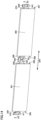
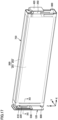
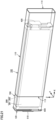
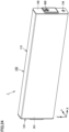
- Fig. 1 is a front view of a secondary battery 1 according to one embodiment.
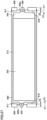
- Figs. 2 to 5 are diagrams showing states of secondary battery 1 shown in Fig. 1 when viewed in directions of arrows II, III, IV, and V respectively.
- Fig. 6 is a front cross sectional view of secondary battery 1 shown in Fig. 1 .
- Secondary battery 1 can be mounted on a battery electric vehicle (BEV), a plug-in hybrid electric vehicle (PHEV), a hybrid electric vehicle (HEV), or the like. It should be noted that the purpose of use of secondary battery 1 is not limited to the use on a vehicle.
- BEV battery electric vehicle
- PHEV plug-in hybrid electric vehicle
- HEV hybrid electric vehicle
- secondary battery 1 includes a case 100, an electrode assembly 200, electrode terminals 300, and current collectors 400.
- Case 100 includes a case main body 110, a sealing plate 120 (first sealing plate), and a sealing plate 130 (second sealing plate).
- a plurality of secondary batteries 1 are stacked in the thickness direction of each of the plurality of secondary batteries 1.
- Secondary batteries 1 stacked may be restrained in the stacking direction (Y direction) by a restraint member to form a battery module, or the battery assembly may be directly supported by a side surface of a case of a battery pack without using the restraint member.
- Case main body 110 is constituted of a member having a tubular shape, preferably, a prismatic tubular shape. Thus, secondary battery 1 having a prismatic shape is obtained.
- Case main body 110 is composed of a metal. Specifically, case main body 110 is composed of aluminum, an aluminum alloy, iron, an iron alloy, or the like.
- sealing plate 120 first wall
- sealing plate 130 second wall
- Case main body 110 can be formed to have a prismatic tubular shape in, for example, the following manner: end sides of a plate-shaped member having been bent are brought into abutment with each other (joining portion 115 illustrated in Fig. 2 ) and are joined together (for example, laser welding).
- Each of the corners of the "prismatic tubular shape” may have a shape with a curvature.
- the secondary battery in the present technology is not necessarily limited to the prismatic secondary battery.
- case main body 110 is formed to be longer in the width direction (X direction) of secondary battery 1 than in each of the thickness direction (Y direction) and the height direction (Z direction) of secondary battery 1.
- the size (width) of case main body 110 in the X direction is preferably about 30 cm or more. In this way, secondary battery 1 can be formed to have a relatively large size (high capacity).
- the size (height) of case main body 110 in the Z direction is preferably about 20 cm or less, more preferably about 15 cm or less, and further preferably about 10 cm or less.
- (low-height) secondary battery 1 having a relatively low height can be formed, thus resulting in improved ease of mounting on a vehicle, for example.
- Case main body 110 includes a pair of first side surface portions 111 and a pair of second side surface portions 112.
- the pair of first side surface portions 111 constitute parts of the side surfaces of case 100.
- the pair of second side surface portions 112 constitute the bottom surface portion and upper surface portion of case 100.
- the pair of first side surface portions 111 and the pair of second side surface portions 112 are provided to intersect each other.
- the pair of first side surface portions 111 and the pair of second side surface portions 112 are connected at their respective end portions.
- Each of the pair of first side surface portions 111 desirably has an area larger than that of each of the pair of second side surface portions 112.
- a gas-discharge valve 150 is provided in one second side surface portion 112A of the pair of second side surface portions 112.
- Gas-discharge valve 150 extends in the width direction (X direction) of secondary battery 1.
- Gas-discharge valve 150 extends from the center of case main body 110 in the X direction to such an extent that gas-discharge valve 150 does not reach both ends of case main body 110 in the X direction. Gas-discharge valve 150 can be changed appropriately.
- the thickness of the plate-shaped member in gas-discharge valve 150 is thinner than the thickness of the plate-shaped member of case main body 110 other than gas-discharge valve 150.
- joining portion 115 is formed at the other second side surface portion 112B of the pair of second side surface portions 112. Joining portion 115 extends in the width direction (X direction) of secondary battery 1. At joining portion 115, the end sides of the plate-shaped member of case main body 110 are joined to each other.
- an opening 113 (first opening) is provided at an end portion of case main body 110 on a first side in the first direction (X direction). Opening 113 is sealed by sealing plate 120. Joining portion 115 is formed at opening 113 so as to seal opening 113.
- Each of opening 113 and sealing plate 120 has a substantially rectangular shape in which the Y direction corresponds to its short-side direction and the Z direction corresponds to its long-side direction. It should be noted that the substantially rectangular shape includes a rectangular shape or a generally rectangular shape such as a rectangular shape having corners each with a curvature.
- Sealing plate 120 (first sealing plate) is provided with a negative electrode terminal 301.
- the position of negative electrode terminal 301 can be appropriately changed.
- an opening 114 (second opening) is provided at an end portion of case main body 110 on a second side opposite to the first side in the first direction (X direction). That is, opening 114 is located at an end portion opposite to opening 113, and openings 113, 114 face each other. Opening 114 is sealed by sealing plate 130. Joining portion 115 is formed at opening 114 so as to seal opening 114.
- Each of opening 114 and sealing plate 130 has a substantially rectangular shape in which the Y direction corresponds to its short-side direction and the Z direction corresponds to its long-side direction.
- Sealing plate 130 (second sealing plate) is provided with a positive electrode terminal 302 and an injection hole 134.
- the positions of positive electrode terminal 302 and injection hole 134 can be appropriately changed.
- Each of sealing plate 120 and sealing plate 130 is composed of a metal. Specifically, each of sealing plate 120 and sealing plate 130 is composed of aluminum, an aluminum alloy, iron, an iron alloy, or the like.
- Negative electrode terminal 301 (first electrode terminal) is electrically connected to a negative electrode of electrode assembly 200. Negative electrode terminal 301 is attached to sealing plate 120, i.e., case 100.
- Positive electrode terminal 302 (second electrode terminal) is electrically connected to a positive electrode of electrode assembly 200. Positive electrode terminal 302 is attached to sealing plate 130, i.e., case 100.
- Negative electrode terminal 301 is composed of a conductive material (more specifically, a metal), and can be composed of copper, a copper alloy, or the like, for example. A portion or layer composed of aluminum or an aluminum alloy may be provided at a portion of an outer surface of negative electrode terminal 301.
- Positive electrode terminal 302 is composed of a conductive material (more specifically, a metal), and can be composed of aluminum, an aluminum alloy, or the like, for example.
- Injection hole 134 is sealed by a sealing member (not shown).
- a sealing member for example, a blind rivet or another metal member can be used.
- Electrode assembly 200 is an electrode assembly having a flat shape and having a below-described positive electrode plate and a below-described negative electrode plate stacked on each other.
- electrode assembly 200 is a stacked type electrode assembly (see Fig. 29 below) in which a plurality of positive electrode plates and a plurality of negative electrode plates are alternately stacked with below-described separators 800 being interposed therebetween.
- the "electrode assembly” is not limited to the stacked type electrode assembly, and may be a wound type electrode assembly (see Fig. 31 below) in which a strip-shaped positive electrode plate and a strip-shaped negative electrode plate are wound together with a strip-shaped separator being interposed therebetween.
- case 100 accommodates electrode assembly 200.
- Fig. 6 illustrates a first electrode assembly 201 described below.
- First electrode assembly 201 is accommodated in case 100 such that the long-side direction thereof is parallel to the X direction.
- electrolyte solution non-aqueous electrolyte solution
- EC ethylene carbonate
- EMC ethyl methyl carbonate
- DMC dimethyl carbonate
- First electrode assembly 201 includes a main body portion having a substantially rectangular shape, a negative electrode tab group 220 (first electrode tab group), and a positive electrode tab group 250 (second electrode tab group).
- the main body portion is constituted of a below-described negative electrode plate 210 and a below-described positive electrode plate 240.
- Negative electrode tab group 220 is located at an end portion of first electrode assembly 201 on the first side with respect to the main body portion thereof in the first direction (X direction).
- the first side in the present embodiment is the sealing plate 120 side.
- Positive electrode tab group 250 is located at an end portion of first electrode assembly 201 on the second side with respect to the main body portion thereof in the first direction (X direction).
- the second side in the present embodiment is the sealing plate 130 side.
- Each of negative electrode tab group 220 and positive electrode tab group 250 is formed to protrude from a central portion of electrode assembly 200 toward sealing plate 120 or sealing plate 130.
- Current collectors 400 include a negative electrode current collector 400A and a positive electrode current collector 400B. Each of negative electrode current collector 400A and positive electrode current collector 400B is constituted of a plate-shaped member. Electrode assembly 200 is electrically connected to negative electrode terminal 301 and positive electrode terminal 302 through current collectors 400.
- Negative electrode current collector 400A is disposed on sealing plate 120 with an insulating member composed of a resin being interposed therebetween. Negative electrode current collector 400A is electrically connected to negative electrode tab group 220 and negative electrode terminal 301. Negative electrode current collector 400A is composed of a conductive material (more specifically, a metal), and can be composed of copper, a copper alloy, or the like, for example. It should be noted that details of negative electrode current collector 400A will be described later.
- Positive electrode current collector 400B is disposed on sealing plate 130 with an insulating member composed of a resin being interposed therebetween. Positive electrode current collector 400B is electrically connected to positive electrode tab group 250 and positive electrode terminal 302. Positive electrode current collector 400B is composed of a conductive material (more specifically, a metal), and can be composed of aluminum, an aluminum alloy, or the like, for example. It should be noted that positive electrode tab group 250 may be electrically connected to sealing plate 130 directly or via positive electrode current collector 400B. In this case, sealing plate 130 may serve as positive electrode terminal 302. Moreover, details of positive electrode current collector 400B will be described later.
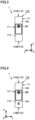
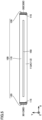
- Fig. 7 is a cross sectional view of negative electrode plate 210 (cross sectional view along VII-VII in Fig. 8), and Fig. 8 is a front view showing negative electrode plate 210.
- a negative electrode tab 230 (first electrode tab) constituted of a negative electrode core body 211 is provided at one end portion, in the width direction, of negative electrode plate 210.
- first electrode tab constituted of a negative electrode core body 211
- a plurality of negative electrode tabs 230 are stacked to form negative electrode tab group 220.
- the length of each of the plurality of negative electrode tabs 230 in the plurality of negative electrode plates 210 in the protruding direction is appropriately adjusted in consideration of the state in which negative electrode tab group 220 is connected to negative electrode current collector 400A.
- the shape of negative electrode tab 230 is not limited to the one illustrated in Fig. 7 .
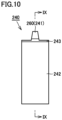
- Fig. 9 is a cross sectional view of positive electrode plate 240 (cross sectional view along IX-IX in Fig. 10), and Fig. 10 is a front view showing positive electrode plate 240.
- a positive electrode tab 260 (second electrode tab) constituted of a positive electrode core body 241 is provided at one end portion, in the width direction, of positive electrode plate 240 formed.
- a plurality of positive electrode tabs 260 are stacked to form positive electrode tab group 250.
- the length of each of positive electrode tabs 260 in the plurality of positive electrode plates 240 in the protruding direction is appropriately adjusted in consideration of the state in which positive electrode tab group 250 is connected to positive electrode current collector 400B. It should be noted that the shape of positive electrode tab 260 is not limited to the one illustrated in Fig. 10 .
- a positive electrode protective layer 243 is provided at the root of positive electrode tab 260.
- Positive electrode protective layer 243 may not necessarily be provided at the root of positive electrode tab 260.
- the thickness of (one) negative electrode tab 230 is smaller than the thickness of (one) positive electrode tab 260.
- the thickness of negative electrode tab group 220 is smaller than the thickness of positive electrode tab group 250.
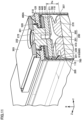
- Fig. 11 is a cross sectional view of the secondary battery shown in Fig. 1 along XI-XI.
- electrode assembly 200 includes first electrode assembly 201 and a second electrode assembly 202.
- Each of first electrode assembly 201 and second electrode assembly 202 includes a positive electrode (second electrode) and a negative electrode (first electrode).
- electrode assembly 200 may be constituted of three or more electrode assemblies.
- Electrode assembly 200 is formed by overlapping first electrode assembly 201 and second electrode assembly 202 with each other.
- First electrode assembly 201 and second electrode assembly 202 are arranged side by side in the thickness direction (Y direction) of each of first electrode assembly 201 and second electrode assembly 202.
- First electrode assembly 201 includes negative electrode tab group 220. Negative electrode tab group 220 is electrically connected to a current collector 410 (negative electrode current collector) at its first end portion 205 in the X direction. Second electrode assembly 202 includes a negative electrode tab group 270. Negative electrode tab group 270 is electrically connected to a current collector 430 (negative electrode current collector) at its third end portion 207 in the X direction.
- Negative electrode tab group 220 has a curved portion 221 and a tip portion 222.
- Curved portion 221 is a portion at which negative electrode tab group 220 is curved on the side, on which the first electrode is connected, with respect to tip portion 222.
- Tip portion 222 is a portion located at an end portion of negative electrode tab group 220 on the side opposite to the side on which the first electrode is connected.
- Negative electrode tab group 270 has a curved portion 271 and a tip portion 272.
- Curved portion 271 is a portion at which negative electrode tab group 270 is curved on the side, on which the first electrode is connected, with respect to tip portion 272.
- Tip portion 272 is a portion located at an end portion of negative electrode tab group 270 on the side opposite to the side on which the first electrode is connected.
- Negative electrode tab group 220 and negative electrode tab group 270 are curved in opposite directions such that tip portions 222, 272 are close to each other. It should be noted that tip portions 222, 272 are separated from each other in the present embodiment; however, it is not limited to this configuration, and tip portions 222, 272 may be in contact with each other.
- Negative electrode current collector 400A electrically connects negative electrode terminal 301 to negative electrode tab group 220 and negative electrode tab group 270. Negative electrode current collector 400A in the present embodiment is connected to negative electrode terminal 301 between electrode assembly 200 and sealing plate 120.
- Negative electrode current collector 400A includes current collector 410, current collector 430 (third current collecting member), and a current collector 440 (fourth current collecting member).
- Current collector 410 is a plate-shaped member.
- Current collector 410 has a long-side direction in the Z direction and a short-side direction in the Y direction.
- Current collector 430 is a plate-shaped member.
- Current collector 430 has a long-side direction in the Z direction and a short-side direction in the Y direction.
- Current collector 410 and current collector 430 are arranged side by side in parallel in the X direction. In this way, current collector 410 and current collector 430 are constituted of separate components.
- Negative electrode tab group 220 is joined to current collector 410 at a joining location 411 described later.
- Negative electrode tab group 270 is joined to current collector 430 at a joining location 431 described later.
- Joining locations 411, 431 can be formed by, for example, ultrasonic welding, resistance welding, laser welding, swaging, or the like.
- negative electrode tab group 220 and current collector 410 are joined by ultrasonic joining, and negative electrode tab group 270 and current collector 430 are joined by ultrasonic joining, for example.
- Current collector 440 is joined to each of current collector 410 and current collector 430 at a joining location (not shown) located at its end portion in the Z direction.
- Current collector 440 is connected to negative electrode terminal 301.
- the connection between current collector 440 and negative electrode terminal 301 can be formed by swaging and/or welding, for example.
- Negative electrode terminal 301 is provided to be exposed to the outside of sealing plate 120 and reach current collector 440 of negative electrode current collector 400A provided on the inner surface side of sealing plate 120. Negative electrode terminal 301 is connected to a plate-shaped member 303.
- Plate-shaped member 303 is located on the outer side with respect to sealing plate 120. Plate-shaped member 303 is disposed along sealing plate 120. Plate-shaped member 303 has electric conductivity. Plate-shaped member 303 is disposed to secure an area of connection with a bus bar or the like that electrically connects secondary battery 1 and another secondary battery adjacent thereto.
- the connection between negative electrode terminal 301 and plate-shaped member 303 can be formed by, for example, laser welding or the like.
- An insulating member 510 is disposed between plate-shaped member 303 and sealing plate 120.
- An insulating member 520 is disposed between negative electrode terminal 301 and sealing plate 120.
- An insulating member 530 is disposed between current collector 440 and sealing plate 120.
- negative electrode terminal 301 may be electrically connected to sealing plate 120. Further, sealing plate 120 may function as negative electrode terminal 301.
- spacer 600 (first spacer) is disposed between sealing plate 120 and the main body portion (negative electrode tab group 220 is not included) of electrode assembly 200.
- Spacer 600 is composed of a resin member having an insulating property.
- spacer 600 is provided with a protrusion 616 protruding in the Y direction. With this protrusion 616 of spacer 600, spacer 600 functions as a guide to facilitate curving of curved portions 221, 271 when forming curved portions 221, 271.
- Insulating sheet 700 (electrode assembly holder) composed of a resin is disposed between electrode assembly 200 and case main body 110.
- Insulating sheet 700 may be composed of, for example, a resin. More specifically, the material of insulating sheet 700 is, for example, polypropylene (PP), polyethylene terephthalate (PET), polyphenylene sulfide (PPS), polyimide (PI), or polyolefin (PO).
- PP polypropylene
- PET polyethylene terephthalate
- PPS polyphenylene sulfide
- PI polyimide
- PO polyolefin
- Fig. 12 is a cross sectional view of the secondary battery shown in Fig. 1 along XII-XII.
- the connection structure between electrode assembly 200 and current collector 400 on the positive electrode side of secondary battery 1 according to the present embodiment is different from that of the configuration on the negative electrode side in the following point: a portion corresponding to current collector 410 and current collector 430 on the negative electrode side is constituted of a single component.
- First electrode assembly 201 includes positive electrode tab group 250. Positive electrode tab group 250 is electrically connected to a current collector 420 (positive electrode current collector) at its second end portion 206 in the X direction. Second electrode assembly 202 includes a positive electrode tab group 280. Positive electrode tab group 280 is electrically connected to current collector 420 (positive electrode current collector) at its fourth end portion 208 in the X direction.
- Positive electrode tab group 250 has a curved portion 251 and a tip portion 252.
- Curved portion 251 is a portion at which positive electrode tab group 250 is curved on the side, on which the second electrode is connected, with respect to tip portion 252.
- Tip portion 252 is a portion located at an end portion of positive electrode tab group 250 on the side opposite to the side on which the second electrode is connected.
- Positive electrode tab group 280 has a curved portion 281 and a tip portion 282.
- Curved portion 281 is a portion at which positive electrode tab group 280 is curved on the side, on which the second electrode is connected, with respect to tip portion 282.
- Tip portion 282 is a portion located at an end portion of positive electrode tab group 280 on the side opposite to the side on which the second electrode is connected.
- Positive electrode tab group 250 and positive electrode tab group 280 are curved in opposite directions such that tip portions 252, 282 are close to each other. It should be noted that tip portions 252, 282 are separated from each other in the present embodiment; however, it is not limited to this configuration, and tip portions 252, 282 may be in contact with each other.
- Positive electrode current collector 400B electrically connects positive electrode terminal 302 to positive electrode tab group 250 and positive electrode tab group 280. Positive electrode current collector 400B in the present embodiment is connected to positive electrode terminal 302 between electrode assembly 200 and sealing plate 130.
- Positive electrode current collector 400B includes current collector 420 (first current collecting member) and a current collector 450 (second current collecting member).
- Current collector 420 is a plate-shaped member.
- Current collector 420 has a long-side direction in the Z direction and a short-side direction in the Y direction.
- Current collector 420 is constituted of a single component in one piece.
- Positive electrode tab group 250 and positive electrode tab group 280 are joined, at below-described joining locations 421, to current collector 420 constituted of the single component.
- Each of joining locations 421 may be formed by ultrasonic welding, resistance welding, laser welding, swaging, or the like, for example.
- positive electrode tab group 250 and positive electrode tab group 280 are joined to current collector 420 by ultrasonic joining, for example.
- Current collector 450 is joined to current collector 420 at a joining location (not shown) located at its end portion in the Z direction.
- Current collector 450 is connected to positive electrode terminal 302.
- the connection between current collector 450 and positive electrode terminal 302 may be formed by swaging and/or welding, for example.
- Positive electrode terminal 302 is provided to be exposed to the outside of sealing plate 130 and reach current collector 450 of positive electrode current collector 400B provided on the inner surface side of sealing plate 130. Positive electrode terminal 302 is connected to a plate-shaped member 304.
- Plate-shaped member 304 is located on the outer side with respect to sealing plate 130. Plate-shaped member 304 is disposed along sealing plate 130. Plate-shaped member 304 has electric conductivity. Plate-shaped member 304 is disposed to secure an area of connection with a bus bar or the like that electrically connects secondary battery 1 and another secondary battery adjacent thereto.
- the connection between positive electrode terminal 302 and plate-shaped member 304 may be formed by, for example, laser welding or the like.
- An insulating member 510 is disposed between plate-shaped member 304 and sealing plate 130.
- An insulating member 520 is disposed between positive electrode terminal 302 and sealing plate 130.
- An insulating member 530 is disposed between current collector 450 and sealing plate 130.
- positive electrode terminal 302 may be electrically connected to sealing plate 130. Further, sealing plate 130 may function as positive electrode terminal 302.
- a spacer 600 (second spacer) is disposed between sealing plate 130 and the main body portion (positive electrode tab groups 250, 280 are not included) of electrode assembly 200.
- Spacer 600 is composed of a resin member having an insulating property.
- spacer 600 is provided with a protrusion 616 protruding in the Y direction. With this protrusion 616 of spacer 600, spacer 600 functions as a guide to facilitate curving of curved portions 251, 281 when forming curved portions 251, 281.
- Insulating sheet 700 (electrode assembly holder) composed of a resin as described above is disposed between electrode assembly 200 and case main body 110.
- Fig. 13 is a flowchart showing a method of manufacturing the secondary battery according to the first embodiment.
- Fig. 14 is a perspective view showing a state before two electrode assemblies included in the secondary battery according to the first embodiment are overlapped with each other.
- Fig. 15 is a cross sectional view of each of the electrode assemblies and the current collectors shown in Fig. 14 along XV-XV.
- first, first electrode assembly 201 and second electrode assembly 202 are produced (step S1). Parts of the tips of negative electrode tab group 220, positive electrode tab group 250, negative electrode tab group 270, and positive electrode tab group 280 are cut such that they have the same tip length when bundled.
- negative electrode tab group 220 is joined to current collector 410 (step S2).
- Negative electrode tab group 220 is joined to current collector 410 at joining location 411.
- negative electrode tab group 270 is joined to current collector 430 (step S3).
- Negative electrode tab group 270 is joined to current collector 430 at joining location 431.
- first electrode assembly 201, current collector 420, and second electrode assembly 202 are disposed side by side in this order in the first direction (DR1 direction).
- Positive electrode tab group 250 is disposed on one side with respect to current collector 420 in the first direction (DR1 direction).
- Positive electrode tab group 250 and positive electrode tab group 280 are joined to current collector 420 with positive electrode tab group 280 being disposed on the other side with respect to current collector 420 in the first direction (DR1 direction) (step S4).
- Positive electrode tab group 250 and positive electrode tab group 280 are joined to current collector 420 at joining locations 421.
- each of current collector 410, current collector 420 and current collector 430 is disposed on one side with respect to the center of each of first electrode assembly 201 and second electrode assembly 202.
- each of the current collectors can be formed to be short, thereby reducing the size of the current collector.
- each of current collector 410, current collector 420, and current collector 430 is not limited to this configuration. In the height direction of each of first electrode assembly 201 and second electrode assembly 202, each of current collector 410, current collector 420, and current collector 430 may be disposed at the center of a corresponding one of first electrode assembly 201 and second electrode assembly 202.
- each of negative electrode tab group 220, positive electrode tab group 250, negative electrode tab group 270, and positive electrode tab group 280 is disposed at the center of a corresponding one of first electrode assembly 201 and second electrode assembly 202 so as to correspond to a corresponding one of current collector 410, current collector 420, and current collector 430.
- each of the respective steps of joining current collector 410 and current collector 430 to first electrode assembly 201 and second electrode assembly 202 is preferably performed before the below-described step of overlapping first electrode assembly 201 and second electrode assembly 202 with each other, and is preferably performed before the step of joining current collector 420 to first electrode assembly 201 and second electrode assembly 202.
- positive electrode tab group 250 and positive electrode tab group 280 are bent in the thickness direction (direction orthogonal to the DR1 direction in Figs. 14 and 15 ) of each of first electrode assembly 201 and second electrode assembly 202, thereby overlapping first electrode assembly 201 and second electrode assembly 202 with each other (step S5). That is, first electrode assembly 201 and second electrode assembly 202 are collected together.
- the first electrode assembly and the second electrode assembly may be overlapped with each other directly, or another member may be disposed between the first electrode assembly and the second electrode assembly. Further, the first electrode assembly and the second electrode assembly may or may not be fixed by a tape or the like. Further, the first electrode assembly, the current collector, and the second electrode assembly may not be disposed on a straight line in the first direction (DR1 direction), and the first electrode assembly or the second electrode assembly may be inclined with respect to the current collector in the first direction (DR1 direction).
- Positive electrode tab group 250 and positive electrode tab group 280 are folded such that tip portions thereof face each other.
- negative electrode tab group 220 and negative electrode tab group 270 are also folded such that tip portions thereof face each other.
- FIG. 13 and 16 is a perspective view showing a state of attaching the holder and the spacer to the electrode assembly. As shown in Fig. 16 , next, spacer 600 and insulating sheet 700 are assembled to electrode assembly 200 (step S6).
- insulating sheet 700 does not necessarily need to cover a whole of the surfaces of electrode assembly 200.
- Insulating sheet 700 preferably covers an area of about 50% or more, more preferably about 70% or more, of the outer surfaces of the electrode assembly.
- Insulating sheet 700 preferably covers a whole of at least four surfaces of the six surfaces of electrode assembly 200 having a substantially rectangular parallelepiped shape (flat shape) other than the two surfaces thereof on which negative electrode tab group 220 and positive electrode tab group 250 are formed respectively.
- Fig. 17 is a perspective view showing a state of attaching sealing plate 120 to the current collectors on the negative electrode side.
- Fig. 18 is a cross sectional view of each of the electrode assemblies and the current collectors shown in Fig. 17 along XVIII-XVIII.
- Figs. 19 and 20 are first and second perspective views each showing an implementation of spacer 600.
- spacer 600 is composed of a resin member having an insulating property.
- Spacer 600 includes: a first component 612 and a second component 614 each having three surrounding side walls; and a coupling wall 611 that couples one side wall of first component 612 and one side wall of second component 614 to each other.
- Protrusion 616 is provided on an inner side of coupling wall 611 so as to extend between first component 612 and second component 614 (in the Z direction).
- First component 612 includes a first plate portion 617 provided to couple the three walls.
- First plate portion 617 is provided with a plurality of first through holes 617s each having an elliptical shape.
- the shape of each first through hole 617s and the number of first through holes 617s are appropriately selected, and are not limited to the shape and number shown.
- Second component 614 includes a second plate portion 618 provided to couple the three walls.
- Second plate portion 618 is provided with a plurality of second through holes 618s each having an elliptical shape.
- the shape of each second through hole 618s and the number of second through holes 618s are appropriately selected, and are not limited to the shape and number shown.
- first plate portion 617 and second plate portion 618 described above is located on an end surface side of the electrode assembly.
- Each of these plate portions may be in abutment with the end surface of the electrode assembly, or when each of these plate portions is not in abutment with the end surface, the shortest distance therebetween is preferably 2 mm or less, and is more preferably 1 mm or less. Further, since first through hole 617s and second through hole 618s are provided, when secondary battery 1 shown in Fig.
- case main body 110 is placed with the Z direction corresponding to the upward direction (such a direction that opening 113 (first opening) and opening 114 (second opening) at the both ends of case main body 110 are arranged on the left and right), even if the electrolyte solution pushed out from the electrode assembly flows to outside of the through holes during charging (generally, the electrode plate is expanded), the electrolyte solution can be readily returned to inside of the electrode assembly during discharging (generally, the electrode plate is contracted).
- step S7 can be performed before step S6.
- negative electrode tab group 220 and negative electrode tab group 270 are folded such that tip portions 222, 272 face each other.
- Each of negative electrode terminal 301 and current collector 440 is attached to sealing plate 120 with an insulating member being interposed therebetween.
- Current collector 440 is brought into abutment with current collector 410 and current collector 430 in the X direction. It should be noted that the connecting of plate-shaped member 303 to negative electrode terminal 301 may be performed at any timing.
- Current collector 440 is joined to current collector 410 and current collector 430 by laser welding from between sealing plate 120 and insulating sheet 700.
- Fig. 21 is a perspective view showing a state of inserting the electrode assemblies into the case main body.
- first electrode assembly 201 and second electrode assembly 202 are inserted into case main body 110 via opening 113 with the current collector 420 side being inserted first (step S8).
- first electrode assembly 201 and second electrode assembly 202 are inserted into case main body 110 with negative electrode active material layer 212 protruding to the negative electrode tab 230 side with respect to the end portion of positive electrode active material layer 242, and details thereof will be described later.
- sealing plate 120 After bringing sealing plate 120 into abutment with case main body 110, sealing plate 120 is temporarily joined to case main body 110. By the temporary joining, sealing plate 120 is partially joined to opening 113 of case main body 110. Thus, sealing plate 120 is positioned with respect to case main body 110.
- electrode assembly 200 When inserting electrode assembly 200 into case main body 110, electrode assembly 200 may be pulled from the current collector 420 side, or may be pushed from each of the current collector 410 side and the current collector 430 side. When electrode assembly 200 is pressed from each of the current collector 410 side and the current collector 430 side, negative electrode tab group 220 and negative electrode tab group 270 can be curved at the same time.
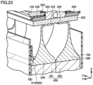
- Fig. 22 is a perspective view showing a state of attaching sealing plate 130 to the current collectors on the positive electrode side.
- Fig. 23 is a cross sectional view of each of the electrode assemblies and the current collectors shown in Fig. 22 along XXIII-XXIII. It should be noted that in Fig. 23 , case main body 110 is not shown.
- current collector 420 is electrically connected to positive electrode terminal 302 after inserting first electrode assembly 201 and second electrode assembly 202 into case main body 110 (step S9).
- each of positive electrode terminal 302 and current collector 450 is attached to sealing plate 130 with an insulating member being interposed therebetween. After inserting first electrode assembly 201 and second electrode assembly 202 into case main body 110, current collector 450 is brought into abutment, in the X direction, with current collector 420 protruding from opening 114. It should be noted that the connecting of plate-shaped portion 304 to positive electrode terminal 302 may be performed at any timing.
- positive electrode tab group 250 and positive electrode tab group 280 connected to current collector 420 are folded such that tip portions 252, 282 face each other.
- sealing plate 130 is brought into abutment with case main body 110.
- positive electrode tab group 250 and positive electrode tab group 280 are curved by bringing sealing plate 130 and the main body portion of electrode assembly 200 close to each other.
- positive electrode tab group 250 and positive electrode tab group 280 are curved along the shape of spacer 600 such that the folded portions of curved portions 251, 281 are close to case main body 110 in the Y direction.
- sealing plate 130 After sealing plate 130 is brought into abutment with case main body 110, sealing plate 130 is temporarily welded to case main body 110. By the temporary joining, sealing plate 130 is partially joined to opening 114 of case main body 110. Thus, sealing plate 130 is positioned with respect to case main body 110.
- Fig. 24 is a perspective view showing the configuration of secondary battery 1.
- sealing plate 120 and sealing plate 130 are joined to case main body 110 (step S10).
- Sealing plate 120 seals opening 113 of case main body 110
- sealing plate 130 seals opening 114 of case main body 110.
- first electrode assembly 201 and second electrode assembly 202 are accommodated in case 100.
- an inspection such as a leakage inspection is performed (step S11).
- secondary battery 1 is dried to remove moisture in case 100.
- the electrolyte solution is injected into case 100 through injection hole 134.
- case 100 is inclined with sealing plate 130 facing upward and sealing plate 120 facing downward, thereby injecting the electrolyte solution into case 100 via injection hole 134 of sealing plate 130.
- charging is performed to result in release of gas.
- injection hole 134 may be temporarily sealed. Thereafter, injection hole 134 is sealed, thereby completing secondary battery 1.
- the order of the step of inserting electrode assembly 200 and the step of connecting the current collectors is not limited to the above-described example.
- negative electrode terminal 301 first electrode terminal
- negative electrode tab groups 220, 270 first electrode tab
- electrode assembly 200 may be inserted into case main body 110 until the end portion of negative electrode active material layer 212 on the opening 113 side is disposed inside case main body 110 (second step). That is, negative electrode terminal 301 and electrode assembly 200 can be electrically connected to each other during the step of inserting electrode assembly 200 into case main body 110.
- first electrode assembly 201 is provided with negative electrode tab group 220 and positive electrode tab group 250 and second electrode assembly 202 is provided with negative electrode tab group 270 and positive electrode tab group 280
- first electrode assembly 201 and second electrode assembly 202 can be configured to have separate electrode tabs.
- the electrode tabs can be shortened as compared with a case where one collective electrode tab is formed by first electrode assembly 201 and second electrode assembly 202 and the electrode tab is bent.
- the occupied volume of the electrode tabs can be reduced, thereby improving the energy density of secondary battery 1.
- the electrode tabs are readily bent and the electrode tabs and the current collectors can be therefore readily joined as compared with the case where one collective electrode tab is formed by first electrode assembly 201 and second electrode assembly 202, with the result that the secondary battery can be stably manufactured.
- secondary battery 1 since secondary battery 1 can be stably manufactured, reliability of the connection portion between each of the electrode tabs and each of the current collectors can be increased.
- Fig. 25 is a cross sectional view taken along a plane including the Z axis with the electrode assembly being inserted in the case main body
- Fig. 26 is a cross sectional view taken along the plane including the Z axis and showing a schematic configuration of electrode assembly 200 after stacking
- Fig. 27 is a cross sectional view taken along the plane including the Z axis and showing a schematic configuration of electrode assembly 200 after the secondary battery is completed. It should be noted that for convenience of description, in each of Figs. 25 to 27 , the current collectors, the case main body, and the sealing plates are not shown as appropriate.
- positive electrode protective layer 243 is provided to protrude to the positive electrode tab 260 side with respect to the end portion of negative electrode active material layer 212 (X1 in the figure), and at the end portion of the main body portion of electrode assembly 200 on the negative electrode tab 230 side, negative electrode active material layer 212 is provided to protrude to the negative electrode tab 230 side with respect to the end portion of positive electrode active material layer 242 (Y1 in the figure).
- separator 800 has a positive-electrode-side protruding region 800x (its protruding length is represented by X2 in the figure) protruding to the positive electrode tab 260 side with respect to the end portion of positive electrode protective layer 243, and at the end portion of separator 800 on the negative electrode tab 230 side, separator 800 has a negative-electrode-side protruding region 800y (its protruding length is represented by Y2 in the figure) protruding to the negative electrode tab 230 side with respect to the end portion of negative electrode active material layer 212.
- the protruding length (Y2) of negative-electrode-side protruding region 800y is provided to be larger than the protruding length (X2) of positive-electrode-side protruding region 800x (Y2>X2).
- electrode assembly 200 is pushed into case main body 110 by external force F applied to sealing plate 120 while first plate portion 617 and second plate portion 618 of spacer 600 are in abutment with the end surface of the electrode assembly, more specifically, are in abutment with negative-electrode-side protruding region 800y.
- electrode assembly 200 is pushed into case main body 110 in a state in which at least portions of the regions of negative-electrode-side protruding region 800y in abutment with spacer 600 are crushed and the region of negative-electrode-side protruding region 800y not in abutment with spacer 600 remains unchanged.
- protruding length X1 of positive electrode protective layer 243 with respect to negative electrode active material layer 212 is about 1.0 mm.
- Protruding length X2 of positive-electrode-side protruding region 800x of separator 800 is about 2.5 mm. It should be noted that protruding length X2 of positive-electrode-side protruding region 800x may be 2 mm or more.
- protruding length Y2 of negative-electrode-side protruding region 800y is about 3.0 mm. It should be noted that protruding length Y2 of negative-electrode-side protruding region 800y may be 2 mm or more.
- a protrusion allowance dimension Tx of positive electrode tab 260 from the end portion of positive electrode protective layer 243 and a protrusion allowance dimension Ty of negative electrode tab 230 from the end portion of negative electrode active material layer 212 before electrode assembly 200 is inserted into the case main body are provided to be substantially the same.
- Electrode assembly 200 After electrode assembly 200 is inserted into the case main body, the configuration on the negative electrode tab 230 side is in the state shown in Fig. 11 , and the configuration on the positive electrode tab 260 side is in the state shown in Fig. 12 .
- positive-electrode-side protruding region 800x of separator 800 is in a state in which the regions thereof in abutment with first plate portion 617 and second plate portion 618 of spacer 600 are crushed.
- a length (X3 in the figure) by which positive-electrode-side protruding region 800x is crushed is less than about 1.5 mm. Therefore, the width of positive-electrode-side protruding region 800x in electrode assembly 200 after being inserted into the case main body is about 1.0 mm to 2.5 mm.
- negative-electrode-side protruding region 800y of separator 800 is also in a state in which the regions thereof in abutment with first plate portion 617 and second plate portion 618 of spacer 600 are crushed.
- a length (Y3 in the figure) by which negative-electrode-side protruding region 800y is crushed is larger than that on the positive-electrode-side protruding region 800x side and exceeds about 1.5 mm. Therefore, the width of negative-electrode-side protruding region 800y in electrode assembly 200 after being inserted into the case main body is about 0.5 mm to 2.5 mm.
- electrode assembly 200 when inserting the electrode assembly into the case main body, electrode assembly 200 is pushed into case main body 110 by external force F applied to sealing plate 120 while first plate portion 617 and second plate portion 618 of spacer 600 are in abutment with negative-electrode-side protruding region 800y.
- negative-electrode-side protruding region 800y of separator 800 serves as a cushion because the protruding length of negative-electrode-side protruding region 800y is provided to be larger than the protruding length of positive-electrode-side protruding region 800x, thereby suppressing damage of the end portion of the negative electrode of the electrode assembly on the negative electrode tab 230 side when inserting electrode assembly 200 into the case main body.
- a space volume from the end portion of negative electrode active material layer 212 on the negative electrode tab 230 side to sealing plate 120 is assumed to be smaller than a space volume from the end portion of positive electrode protective layer 243 on the positive electrode tab 260 side to sealing plate 130.
- protrusion allowance dimension Tx of positive electrode tab 260 from the end portion of positive electrode protective layer 243 and protrusion allowance dimension Ty of positive electrode tab 260 from the end portion of negative electrode active material layer 212 before electrode assembly 200 is inserted into the case main body are provided to be substantially the same; however, after the manufacturing of secondary battery 1 is completed, a distance Hy (distance from the root of the tab to the current collector) shown in Fig. 12 (positive electrode side) is assumed to be larger than a distance Hx (distance from the root of the tab to the current collector) shown in Fig. 11 (negative electrode side).
- positive electrode core body 241 is composed of, for example, a metal foil containing aluminum, an aluminum alloy, or the like.
- the thickness of positive electrode core body 241 is, for example, about 3 ⁇ m or more, and is preferably about 5 ⁇ m or more.
- the thickness of positive electrode core body 241 is, for example, about 30 ⁇ m or less, and is preferably about 20 ⁇ m or less.
- Positive electrode active material layer 242 includes a positive electrode active material.
- Positive electrode active material layer 242 may include a binder (such as PVDF) or a conductive member (such as a carbon material) in addition to the positive electrode active material.
- the positive electrode active material is preferably a lithium transition metal composite oxide or the like.
- the positive electrode active material may be a mixture of a plurality of types of materials.
- the thickness of positive electrode active material layer 242 is preferably about 30 ⁇ m or more, is more preferably about 40 ⁇ m or more, and is further preferably about 50 ⁇ m or more, for example.
- the thickness of positive electrode active material layer 242 is preferably about 500 ⁇ m or less, and is more preferably about 300 ⁇ m or less, for example.
- Positive electrode protective layer 243 has higher electric resistance than that of positive electrode active material layer 242.
- Positive electrode protective layer 243 includes substantially no positive electrode active material or includes only a slight amount of the positive electrode active material.
- the mass of the positive electrode active material therein with respect to the total mass of positive electrode protective layer 243 is about 5% or less, and is preferably about 1% or less.
- Positive electrode protective layer 243 preferably includes inorganic particles (for example, alumina, boehmite, or the like). Positive electrode protective layer 243 preferably includes the inorganic particles and a binder. Positive electrode protective layer 243 preferably includes about 50 mass% or more of the inorganic particles. Positive electrode protective layer 243 may be an insulating resin layer or may include a carbon material having electric conductivity.
- inorganic particles for example, alumina, boehmite, or the like.
- Positive electrode protective layer 243 preferably includes the inorganic particles and a binder.
- Positive electrode protective layer 243 preferably includes about 50 mass% or more of the inorganic particles.
- Positive electrode protective layer 243 may be an insulating resin layer or may include a carbon material having electric conductivity.
- Positive electrode protective layer 243 is preferably formed on positive electrode core body 241 along an end portion of its portion at which positive electrode active material layer 242 is formed. Positive electrode protective layer 243 is preferably disposed to face the end portion of negative electrode active material layer 212 with a separator (insulating sheet) being interposed therebetween. Thus, a short circuit between positive electrode core body 241 and the end portion of negative electrode active material layer 212 can be suppressed.
- the thickness of positive electrode protective layer 243 is preferably smaller than the thickness of positive electrode active material layer 242.
- the thickness of positive electrode protective layer 243 is preferably about 10 ⁇ m or more, is more preferably about 20 ⁇ m or more, and is further preferably about 30 ⁇ m or more.
- the thickness of positive electrode protective layer 243 is preferably about 200 ⁇ m or less, is more preferably about 100 ⁇ m or less, and is further preferably about 50 ⁇ m or less, for example.
- negative electrode core body 211 is preferably composed of a metal including, for example, copper or a copper alloy, and is more preferably composed of a metal foil.
- the thickness of negative electrode core body 211 is, for example, about 3 ⁇ m or more, and is preferably about 5 ⁇ m or more.
- the thickness of negative electrode core body 211 is, for example, about 30 ⁇ m or less, and is preferably about 20 ⁇ m or less.
- Negative electrode active material layer 212 includes a negative electrode active material. Negative electrode active material layer 212 may include a binder (such as SBR or CMC) and a conductive member (such as a carbon material) in addition to the negative electrode active material.
- the negative electrode active material is preferably a carbon material such as graphite or a silicon material such as SiO or SiC.
- the negative electrode active material may be a mixture of a plurality of types of materials.
- the thickness of negative electrode active material layer 212 is preferably about 50 ⁇ m or more, is more preferably about 60 ⁇ m or more, and is further preferably about 70 ⁇ m or more, for example.
- the thickness of negative electrode active material layer 212 is preferably about 500 ⁇ m or less, and is more preferably about 300 ⁇ m or less, for example.
- separator 800 Since separator 800 is greatly crushed on the negative electrode tab 230 side as described above, separator 800 preferably has strength to some extent and it is preferable to use, for example, a material having a tensile break strength of 500 kgf/cm 2 or more in a TD direction, which is a direction of crushing.
- the material include a single-layer film or stacked-layer film composed of polyethylene, polypropylene, or the like and having a thickness of about 5 ⁇ m to 20 ⁇ m.
- an insulating heat-resistant layer including a ceramic such as alumina, boehmite, or magnesia and a binder (such as PVDF) may be formed on one surface or each of both surfaces of the separator.
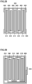
- Figs. 29 and 30 are schematic cross sectional views showing various implementations of the electrode assembly. It should be noted that in each of the figures, a separator fixing tape 900 is shown.
- the electrode assembly there is employed a stacked type electrode assembly of an individual-sheet type in which independent separators 800 are disposed between negative electrode plates 210 and positive electrode plates 240 as shown in Fig. 28 ; however, the implementation of the electrode assembly is not limited thereto.
- a stacked type electrode assembly of a meandering type in which one separator 800 is disposed to extend back and forth between negative electrode plates 210 and positive electrode plates 240.
- a wound type electrode assembly in which a separator 800 is disposed between negative electrode plate 210 and positive electrode plate 240 and is wound around an axis.
- the meandering type of the stacked type rigidity is obtained in folded portions of the separator at its upper and lower ends and the electrode plates are less likely to be damaged as compared with the individual-sheet type of the stacked type. Therefore, the meandering type is considered to be suitable for the step of inserting the electrode assembly into the case main body and the step of injecting the electrolyte solution into the case in the present embodiment.
Landscapes
- Chemical & Material Sciences (AREA)
- Chemical Kinetics & Catalysis (AREA)
- Electrochemistry (AREA)
- General Chemical & Material Sciences (AREA)
- Engineering & Computer Science (AREA)
- Manufacturing & Machinery (AREA)
- Materials Engineering (AREA)
- Connection Of Batteries Or Terminals (AREA)
- Secondary Cells (AREA)
- Sealing Battery Cases Or Jackets (AREA)
- Cell Separators (AREA)
Abstract
In a method of manufacturing a secondary battery, a separator (800) has a positive-electrode-side protruding region (800x) protruding to a positive electrode tab (260) side with respect to an end portion of a positive electrode protective layer (243), at an end portion of the separator (800) on a negative electrode tab (230) side, the separator (800) has a negative-electrode-side protruding region (800y) protruding to the negative electrode tab (230) side with respect to an end portion of a negative electrode active material layer (212), and at the negative-electrode-side protruding region (800y), the separator (800) has a region crushed by the first spacer (600).
Description
- This nonprovisional application is based on
Japanese Patent Application No. 2023-194371 filed on November 15, 2023 - The present technology relates to a secondary battery and a method of manufacturing the secondary battery.
-
U.S. Patent Publication No. 2022/0302533 discloses a structure in which electrode tab groups are provided at both ends of an electrode assembly and the electrode tab groups are connected to electrode terminals at both ends of a battery case in a long-side direction thereof. Components that accommodate the electrode tab groups at the both end sides of the battery case are provided to simplify each of the shapes of the electrode tab groups, thereby suppressing a current collecting path from being long in length. - When inserting the electrode assembly into the battery case and/or when raising the case at the time of injection, the electrode assembly (a negative electrode active material layer present at a corner portion) may be damaged. Further, when inserting the electrode assembly into the battery case and/or when raising the case at the time of injection, an end portion of the negative electrode located at a lower end thereof may be brought into contact with a spacer, a current collector or the like, and may be accordingly damaged.
- An object of the present technology is to provide a secondary battery and a method of manufacturing the secondary battery to avoid possible damage of an electrode assembly when inserting the electrode assembly into a battery case and/or when raising the case at the time of injection so as to attain high energy density and high reliability.
- The present technology provides the following secondary battery and the following method of manufacturing the secondary battery.
- [1] A secondary battery comprising: an electrode assembly in which a positive electrode plate and a negative electrode plate are stacked with a separator being interposed between the positive electrode plate and the negative electrode plate; and a case that accommodates the electrode assembly, wherein the case includes a case main body provided with a first opening at one end portion of the case main body and a second opening at the other end portion of the case main body, a first sealing plate that seals the first opening, and a second sealing plate that seals the second opening, a first spacer is disposed between the first sealing plate and the electrode assembly, a second spacer is disposed between the second sealing plate and the electrode assembly, the positive electrode plate has a positive electrode tab at an end portion of the positive electrode plate on the second sealing plate side, the negative electrode plate has a negative electrode tab at an end portion of the negative electrode plate on the first sealing plate side, the positive electrode plate includes a positive electrode core body, a positive electrode active material layer formed on the positive electrode core body, and a positive electrode protective layer formed on the positive electrode core body, in the positive electrode plate, the positive electrode protective layer is located on the positive electrode tab side with respect to the positive electrode active material layer, the negative electrode plate includes a negative electrode core body and a negative electrode active material layer formed on the negative electrode core body, at an end portion of the separator on the positive electrode tab side, the separator has a positive-electrode-side protruding region protruding to the positive electrode tab side with respect to an end portion of the positive electrode protective layer, at an end portion of the separator on the negative electrode tab side, the separator has a negative-electrode-side protruding region protruding to the negative electrode tab side with respect to an end portion of the negative electrode active material layer, and at the negative-electrode-side protruding region, the separator has a region crushed by the first spacer.
- [2] The secondary battery according to [1], wherein at the positive-electrode-side protruding region, the separator has a region crushed by the second spacer, and a width by which the negative-electrode-side protruding region is crushed is larger than a width by which the positive-electrode-side protruding region is crushed.
- [3] The secondary battery according to [1] or [2], wherein in the separator, a width of the negative-electrode-side protruding region is larger than a width of the positive-electrode-side protruding region.
- [4] The secondary battery according to any one of [1] to [3], wherein a space volume from the end portion of the negative electrode active material layer to the first sealing plate is smaller than a space volume from the end portion of the positive electrode protective layer to the second sealing plate.
- [5] A method of manufacturing a secondary battery, the method comprising: producing an electrode assembly in which a positive electrode plate and a negative electrode plate are stacked with a separator being interposed between the positive electrode plate and the negative electrode plate; and accommodating the electrode assembly in a case, wherein the case includes a case main body provided with a first opening at one end portion of the case main body and a second opening at the other end portion of the case main body, a first sealing plate that seals the first opening, and a second sealing plate that seals the second opening, the accommodating the electrode assembly in the case includes inserting the electrode assembly into the case main body through the first opening, the electrode assembly has a main body portion, a positive electrode tab located on the second sealing plate side with respect to the main body portion and provided on the positive electrode plate, and a negative electrode tab located on the first sealing plate side with respect to the main body portion and provided on the negative electrode plate, the positive electrode plate includes a positive electrode core body, a positive electrode active material layer formed on the positive electrode core body, and a positive electrode protective layer formed on the positive electrode core body, in the positive electrode plate, the positive electrode protective layer is located on the positive electrode tab side with respect to the positive electrode active material layer, the negative electrode plate includes a negative electrode core body and a negative electrode active material layer formed on the negative electrode core body, at an end portion of the main body portion of the electrode assembly on the positive electrode tab side, the positive electrode protective layer protrudes to the positive electrode tab side with respect to an end portion of the negative electrode active material layer, at an end portion of the main body portion of the electrode assembly on the negative electrode tab side, the negative electrode active material layer protrudes to the negative electrode tab side with respect to an end portion of the positive electrode active material layer, at an end portion of the separator on the positive electrode tab side, the separator has a positive-electrode-side protruding region protruding to the positive electrode tab side with respect to an end portion of the positive electrode protective layer, at an end portion of the separator on the negative electrode tab side, the separator has a negative-electrode-side protruding region protruding to the negative electrode tab side with respect to an end portion of the negative electrode active material layer, and a protruding length of the negative-electrode-side protruding region is larger than a protruding length of the positive-electrode-side protruding region.
- [6] The method of manufacturing a secondary battery according to [5], wherein each of the protruding length of the negative-electrode-side protruding region and the protruding length of the positive-electrode-side protruding region is 2 mm or more.
- [7] The method of manufacturing a secondary battery according to [5] or [6], wherein the inserting the electrode assembly into the case main body through the first opening includes inserting the electrode assembly into the case main body through the first opening with the spacer being disposed between the first sealing plate and the electrode assembly, and the negative-electrode-side protruding region is accommodated in the case main body with the negative-electrode-side protruding region being crushed at a region in abutment with the spacer.
- [8] The method of manufacturing a secondary battery according to any one of [5] to [7], wherein the electrode assembly is inserted into the case main body from an end portion of the electrode assembly on a side on which the positive electrode tab is disposed.
- [9] The method of manufacturing a secondary battery according to [8], wherein after the negative electrode tab and the first sealing plate are connected to each other, the electrode assembly is inserted into the case main body.
- [10] The method of manufacturing a secondary battery according to [8], wherein after the electrode assembly is inserted into the case main body, the positive electrode tab and the second sealing plate are connected to each other.
- [11] The method of manufacturing a secondary battery according to any one of [5] to [10], wherein the negative electrode tab is electrically connected, through a negative electrode current collector, to a negative electrode terminal attached to the first sealing plate.
- [12] The method of manufacturing a secondary battery according to any one of [5] to [10], wherein the positive electrode tab is electrically connected, through a positive electrode current collector, to a positive electrode terminal attached to the second sealing plate.
- The foregoing and other objects, features, aspects and advantages of the present invention will become more apparent from the following detailed description of the present invention when taken in conjunction with the accompanying drawings.
-
-
Fig. 1 is a front view showing a configuration of a secondary battery according to one embodiment. -
Fig. 2 is a diagram showing a state in which the secondary battery shown inFig. 1 is viewed in a direction of arrow II. -
Fig. 3 is a diagram showing a state in which the secondary battery shown inFig. 1 is viewed in a direction of arrow III. -
Fig. 4 is a diagram showing a state in which the secondary battery shown inFig. 1 is viewed in a direction of arrow IV. -
Fig. 5 is a diagram showing a state in which the secondary battery shown inFig. 1 is viewed in a direction of arrow V. -
Fig. 6 is a front cross sectional view of the secondary battery shown inFig. 1 . -
Fig. 7 is a cross sectional view of a negative electrode plate. -
Fig. 8 is a front view showing the negative electrode plate. -
Fig. 9 is a cross sectional view of a positive electrode plate. -
Fig. 10 is a front view showing the positive electrode plate. -
Fig. 11 is a cross sectional view of the secondary battery shown inFig. 1 along XI-XI. -
Fig. 12 is a cross sectional view of the secondary battery shown inFig. 1 along XII-XII. -
Fig. 13 is a flowchart showing a method of manufacturing the secondary battery according to one embodiment. -
Fig. 14 is a perspective view showing a state before two electrode assemblies included in the secondary battery according to one embodiment are overlapped with each other. -
Fig. 15 is a cross sectional view of each of the electrode assemblies and the current collectors shown inFig. 14 along XV-XV. -
Fig. 16 is a perspective view showing a state of attaching a holder and a spacer to the electrode assembly. -
Fig. 17 is a perspective view showing a state of attaching a sealing plate to the current collectors on the negative electrode side. -
Fig. 18 is a cross sectional view of each of the electrode assemblies and the current collectors shown inFig. 17 along XVIII-XVIII. -
Fig. 19 is a first perspective view showing an implementation of the spacer. -
Fig. 20 is a second perspective view showing the implementation of the spacer. -
Fig. 21 is a perspective view showing a state of inserting the electrode assemblies into the case main body. -
Fig. 22 is a perspective view showing a state of attaching a sealing plate to current collectors on the positive electrode side. -
Fig. 23 is a cross sectional view of each of the electrode assemblies and the current collectors shown inFig. 22 along XXIII-XXIII. -
Fig. 24 is a perspective view showing a configuration of the secondary battery. -
Fig. 25 is a cross sectional view taken along a plane including the Z axis with the electrode assembly being inserted in the case main body. -
Fig. 26 is a cross sectional view taken along the plane including the Z axis and showing a schematic configuration of the electrode assembly after stacking. -
Fig. 27 is a cross sectional view taken along the plane including the Z axis and showing a schematic configuration of the electrode assembly after the secondary battery is completed. -
Fig. 28 is a schematic cross sectional view showing an implementation (individual-sheet type) of the electrode assembly. -
Fig. 29 is a schematic cross sectional view showing an implementation (meandering type) of the electrode assembly. -
Fig. 30 is a schematic cross sectional view showing an implementation (wound type) of the electrode assembly. - Hereinafter, embodiments of the present technology will be described. It should be noted that the same or corresponding portions are denoted by the same reference characters, and may not be described repeatedly.
- It should be noted that in the embodiments described below, when reference is made to number, amount, and the like, the scope of the present technology is not necessarily limited to the number, amount, and the like unless otherwise stated particularly. Further, in the embodiments described below, each component is not necessarily essential to the present technology unless otherwise stated particularly. Further, the present technology is not limited to one that necessarily exhibits all the functions and effects stated in the present embodiment.
- It should be noted that in the present specification, the terms "comprise", "include", and "have" are open-end terms. That is, when a certain configuration is included, a configuration other than the foregoing configuration may or may not be included.
- Also, in the present specification, when geometric terms and terms representing positional/directional relations are used, for example, when terms such as "parallel", "orthogonal", "obliquely at 45°", "coaxial", and "along" are used, these terms permit manufacturing errors or slight fluctuations. In the present specification, when terms representing relative positional relations such as "upper side" and "lower side" are used, each of these terms is used to indicate a relative positional relation in one state, and the relative positional relation may be reversed or turned at any angle in accordance with an installation direction of each mechanism (for example, the entire mechanism is reversed upside down).
- In the present specification, the term "secondary battery" is not limited to a lithium ion battery, and may include other secondary batteries such as a nickel-metal hydride battery and a sodium-ion battery. In the present specification, the term "electrode" may collectively represent a positive electrode and a negative electrode.
- It should be noted that in the figures, when the electrode assembly included in the secondary battery is a stacked type electrode assembly, the X direction is defined as a long-side direction of a stacked surface, whereas when the electrode assembly is a wound type electrode assembly, the X direction is defined as a direction along a winding axis thereof. Further, the Y direction is defined as a short-side direction of the electrode assembly when viewed in the X direction, and the Z direction is defined as a long-side direction of the electrode assembly when viewed in the X direction. In order to facilitate understanding of the invention, the size of each configuration in the figures may be illustrated to be changed from its actual size.
- In the specification of the present application, the first direction (X direction) may be referred to as a "width direction" of the secondary battery or the case main body, the second direction (Z direction) may be referred to as a "height direction" of the secondary battery or the case main body, and the third direction (Y direction) may be referred to as a "thickness direction" of the secondary battery or the case main body.
-
Fig. 1 is a front view of asecondary battery 1 according to one embodiment.Figs. 2 to 5 are diagrams showing states ofsecondary battery 1 shown inFig. 1 when viewed in directions of arrows II, III, IV, and V respectively.Fig. 6 is a front cross sectional view ofsecondary battery 1 shown inFig. 1 . -
Secondary battery 1 can be mounted on a battery electric vehicle (BEV), a plug-in hybrid electric vehicle (PHEV), a hybrid electric vehicle (HEV), or the like. It should be noted that the purpose of use ofsecondary battery 1 is not limited to the use on a vehicle. - As shown in
Figs. 1 to 6 ,secondary battery 1 includes acase 100, anelectrode assembly 200,electrode terminals 300, andcurrent collectors 400.Case 100 includes a casemain body 110, a sealing plate 120 (first sealing plate), and a sealing plate 130 (second sealing plate). - When forming a battery assembly including
secondary battery 1, a plurality ofsecondary batteries 1 are stacked in the thickness direction of each of the plurality ofsecondary batteries 1.Secondary batteries 1 stacked may be restrained in the stacking direction (Y direction) by a restraint member to form a battery module, or the battery assembly may be directly supported by a side surface of a case of a battery pack without using the restraint member. - Case
main body 110 is constituted of a member having a tubular shape, preferably, a prismatic tubular shape. Thus,secondary battery 1 having a prismatic shape is obtained. Casemain body 110 is composed of a metal. Specifically, casemain body 110 is composed of aluminum, an aluminum alloy, iron, an iron alloy, or the like. - As shown in
Figs. 1 and2 , sealing plate 120 (first wall) and sealing plate 130 (second wall) are provided at respective end portions of the case main body. Casemain body 110 can be formed to have a prismatic tubular shape in, for example, the following manner: end sides of a plate-shaped member having been bent are brought into abutment with each other (joiningportion 115 illustrated inFig. 2 ) and are joined together (for example, laser welding). Each of the corners of the "prismatic tubular shape" may have a shape with a curvature. Moreover, the secondary battery in the present technology is not necessarily limited to the prismatic secondary battery. - In the present embodiment, case
main body 110 is formed to be longer in the width direction (X direction) ofsecondary battery 1 than in each of the thickness direction (Y direction) and the height direction (Z direction) ofsecondary battery 1. The size (width) of casemain body 110 in the X direction is preferably about 30 cm or more. In this way,secondary battery 1 can be formed to have a relatively large size (high capacity). The size (height) of casemain body 110 in the Z direction is preferably about 20 cm or less, more preferably about 15 cm or less, and further preferably about 10 cm or less. Thus, (low-height)secondary battery 1 having a relatively low height can be formed, thus resulting in improved ease of mounting on a vehicle, for example. - Case
main body 110 includes a pair of firstside surface portions 111 and a pair of secondside surface portions 112. The pair of firstside surface portions 111 constitute parts of the side surfaces ofcase 100. The pair of secondside surface portions 112 constitute the bottom surface portion and upper surface portion ofcase 100. The pair of firstside surface portions 111 and the pair of secondside surface portions 112 are provided to intersect each other. The pair of firstside surface portions 111 and the pair of secondside surface portions 112 are connected at their respective end portions. Each of the pair of firstside surface portions 111 desirably has an area larger than that of each of the pair of secondside surface portions 112. - As shown in
Fig. 5 , a gas-discharge valve 150 is provided in one secondside surface portion 112A of the pair of secondside surface portions 112. Gas-discharge valve 150 extends in the width direction (X direction) ofsecondary battery 1. Gas-discharge valve 150 extends from the center of casemain body 110 in the X direction to such an extent that gas-discharge valve 150 does not reach both ends of casemain body 110 in the X direction. Gas-discharge valve 150 can be changed appropriately. - The thickness of the plate-shaped member in gas-
discharge valve 150 is thinner than the thickness of the plate-shaped member of casemain body 110 other than gas-discharge valve 150. Thus, when the pressure incase 100 becomes equal to or more than a predetermined value, gas-discharge valve 150 is fractured prior to the other portions of casemain body 110, thereby discharging the gas incase 100 to the outside. - As shown in
Fig. 2 , joiningportion 115 is formed at the other secondside surface portion 112B of the pair of secondside surface portions 112. Joiningportion 115 extends in the width direction (X direction) ofsecondary battery 1. At joiningportion 115, the end sides of the plate-shaped member of casemain body 110 are joined to each other. - As shown in
Fig. 3 , an opening 113 (first opening) is provided at an end portion of casemain body 110 on a first side in the first direction (X direction).Opening 113 is sealed by sealingplate 120. Joiningportion 115 is formed at opening 113 so as to sealopening 113. Each ofopening 113 and sealingplate 120 has a substantially rectangular shape in which the Y direction corresponds to its short-side direction and the Z direction corresponds to its long-side direction. It should be noted that the substantially rectangular shape includes a rectangular shape or a generally rectangular shape such as a rectangular shape having corners each with a curvature. - Sealing plate 120 (first sealing plate) is provided with a
negative electrode terminal 301. The position ofnegative electrode terminal 301 can be appropriately changed. - As shown in
Fig. 4 , an opening 114 (second opening) is provided at an end portion of casemain body 110 on a second side opposite to the first side in the first direction (X direction). That is, opening 114 is located at an end portion opposite to opening 113, andopenings Opening 114 is sealed by sealingplate 130. Joiningportion 115 is formed at opening 114 so as to sealopening 114. Each ofopening 114 and sealingplate 130 has a substantially rectangular shape in which the Y direction corresponds to its short-side direction and the Z direction corresponds to its long-side direction. - Sealing plate 130 (second sealing plate) is provided with a
positive electrode terminal 302 and aninjection hole 134. The positions ofpositive electrode terminal 302 andinjection hole 134 can be appropriately changed. - Each of sealing
plate 120 and sealingplate 130 is composed of a metal. Specifically, each of sealingplate 120 and sealingplate 130 is composed of aluminum, an aluminum alloy, iron, an iron alloy, or the like. - Negative electrode terminal 301 (first electrode terminal) is electrically connected to a negative electrode of
electrode assembly 200.Negative electrode terminal 301 is attached to sealingplate 120, i.e.,case 100. - Positive electrode terminal 302 (second electrode terminal) is electrically connected to a positive electrode of
electrode assembly 200.Positive electrode terminal 302 is attached to sealingplate 130, i.e.,case 100. -
Negative electrode terminal 301 is composed of a conductive material (more specifically, a metal), and can be composed of copper, a copper alloy, or the like, for example. A portion or layer composed of aluminum or an aluminum alloy may be provided at a portion of an outer surface ofnegative electrode terminal 301. -
Positive electrode terminal 302 is composed of a conductive material (more specifically, a metal), and can be composed of aluminum, an aluminum alloy, or the like, for example. -
Injection hole 134 is sealed by a sealing member (not shown). As the sealing member, for example, a blind rivet or another metal member can be used. -
Electrode assembly 200 is an electrode assembly having a flat shape and having a below-described positive electrode plate and a below-described negative electrode plate stacked on each other. Specifically,electrode assembly 200 is a stacked type electrode assembly (seeFig. 29 below) in which a plurality of positive electrode plates and a plurality of negative electrode plates are alternately stacked with below-describedseparators 800 being interposed therebetween. However, in the present specification, the "electrode assembly" is not limited to the stacked type electrode assembly, and may be a wound type electrode assembly (see Fig. 31 below) in which a strip-shaped positive electrode plate and a strip-shaped negative electrode plate are wound together with a strip-shaped separator being interposed therebetween. The separator can be constituted of, for example, a microporous membrane composed of polyolefin. When the electrode assembly is the stacked type electrode assembly including the plurality of positive electrode plates and the plurality of negative electrode plates, positive electrode tabs provided on the positive electrode plates may be stacked to form a positive electrode tab group, and negative electrode tabs provided on the negative electrode plates may be stacked to form a negative electrode tab group. - As shown in
Fig. 6 ,case 100 accommodateselectrode assembly 200.Fig. 6 illustrates afirst electrode assembly 201 described below.First electrode assembly 201 is accommodated incase 100 such that the long-side direction thereof is parallel to the X direction. - Specifically, one or a plurality of the stacked type electrode assemblies and an electrolyte solution (electrolyte) (not shown) are accommodated inside a below-described
insulating sheet 700 disposed incase 100. As the electrolyte solution (non-aqueous electrolyte solution), it is possible to use, for example, a solution obtained by dissolving LiPF6 at a concentration of 1.2 mol/L in a non-aqueous solvent obtained by mixing ethylene carbonate (EC), ethyl methyl carbonate (EMC), and dimethyl carbonate (DMC) at a volume ratio (25°C) of 30:30:40. It should be noted that instead of the electrolyte solution, a solid electrolyte may be used. -
First electrode assembly 201 includes a main body portion having a substantially rectangular shape, a negative electrode tab group 220 (first electrode tab group), and a positive electrode tab group 250 (second electrode tab group). - The main body portion is constituted of a below-described
negative electrode plate 210 and a below-describedpositive electrode plate 240. Negativeelectrode tab group 220 is located at an end portion offirst electrode assembly 201 on the first side with respect to the main body portion thereof in the first direction (X direction). The first side in the present embodiment is the sealingplate 120 side. Positiveelectrode tab group 250 is located at an end portion offirst electrode assembly 201 on the second side with respect to the main body portion thereof in the first direction (X direction). The second side in the present embodiment is the sealingplate 130 side. - Each of negative
electrode tab group 220 and positiveelectrode tab group 250 is formed to protrude from a central portion ofelectrode assembly 200 toward sealingplate 120 or sealingplate 130. -
Current collectors 400 include a negative electrodecurrent collector 400A and a positive electrodecurrent collector 400B. Each of negative electrodecurrent collector 400A and positive electrodecurrent collector 400B is constituted of a plate-shaped member.Electrode assembly 200 is electrically connected tonegative electrode terminal 301 andpositive electrode terminal 302 throughcurrent collectors 400. - Negative electrode
current collector 400A is disposed on sealingplate 120 with an insulating member composed of a resin being interposed therebetween. Negative electrodecurrent collector 400A is electrically connected to negativeelectrode tab group 220 andnegative electrode terminal 301. Negative electrodecurrent collector 400A is composed of a conductive material (more specifically, a metal), and can be composed of copper, a copper alloy, or the like, for example. It should be noted that details of negative electrodecurrent collector 400A will be described later. - Positive electrode
current collector 400B is disposed on sealingplate 130 with an insulating member composed of a resin being interposed therebetween. Positive electrodecurrent collector 400B is electrically connected to positiveelectrode tab group 250 andpositive electrode terminal 302. Positive electrodecurrent collector 400B is composed of a conductive material (more specifically, a metal), and can be composed of aluminum, an aluminum alloy, or the like, for example. It should be noted that positiveelectrode tab group 250 may be electrically connected to sealingplate 130 directly or via positive electrodecurrent collector 400B. In this case, sealingplate 130 may serve aspositive electrode terminal 302. Moreover, details of positive electrodecurrent collector 400B will be described later. -
Fig. 7 is a cross sectional view of negative electrode plate 210 (cross sectional view along VII-VII inFig. 8), and Fig. 8 is a front view showingnegative electrode plate 210. - As shown in
Fig. 8 , a negative electrode tab 230 (first electrode tab) constituted of a negativeelectrode core body 211 is provided at one end portion, in the width direction, ofnegative electrode plate 210. Whennegative electrode plates 210 are stacked, a plurality ofnegative electrode tabs 230 are stacked to form negativeelectrode tab group 220. The length of each of the plurality ofnegative electrode tabs 230 in the plurality ofnegative electrode plates 210 in the protruding direction is appropriately adjusted in consideration of the state in which negativeelectrode tab group 220 is connected to negative electrodecurrent collector 400A. It should be noted that the shape ofnegative electrode tab 230 is not limited to the one illustrated inFig. 7 . -
Fig. 9 is a cross sectional view of positive electrode plate 240 (cross sectional view along IX-IX inFig. 10), and Fig. 10 is a front view showingpositive electrode plate 240. - As shown in
Fig. 10 , a positive electrode tab 260 (second electrode tab) constituted of a positiveelectrode core body 241 is provided at one end portion, in the width direction, ofpositive electrode plate 240 formed. Whenpositive electrode plates 240 are stacked, a plurality ofpositive electrode tabs 260 are stacked to form positiveelectrode tab group 250. The length of each ofpositive electrode tabs 260 in the plurality ofpositive electrode plates 240 in the protruding direction is appropriately adjusted in consideration of the state in which positiveelectrode tab group 250 is connected to positive electrodecurrent collector 400B. It should be noted that the shape ofpositive electrode tab 260 is not limited to the one illustrated inFig. 10 . - A positive electrode
protective layer 243 is provided at the root ofpositive electrode tab 260. Positive electrodeprotective layer 243 may not necessarily be provided at the root ofpositive electrode tab 260. - In a typical example, the thickness of (one)
negative electrode tab 230 is smaller than the thickness of (one)positive electrode tab 260. In this case, the thickness of negativeelectrode tab group 220 is smaller than the thickness of positiveelectrode tab group 250. -
Fig. 11 is a cross sectional view of the secondary battery shown inFig. 1 along XI-XI. As shown inFig. 11 ,electrode assembly 200 includesfirst electrode assembly 201 and asecond electrode assembly 202. Each offirst electrode assembly 201 andsecond electrode assembly 202 includes a positive electrode (second electrode) and a negative electrode (first electrode). It should be noted thatelectrode assembly 200 may be constituted of three or more electrode assemblies. -
Electrode assembly 200 is formed by overlappingfirst electrode assembly 201 andsecond electrode assembly 202 with each other.First electrode assembly 201 andsecond electrode assembly 202 are arranged side by side in the thickness direction (Y direction) of each offirst electrode assembly 201 andsecond electrode assembly 202. -
First electrode assembly 201 includes negativeelectrode tab group 220. Negativeelectrode tab group 220 is electrically connected to a current collector 410 (negative electrode current collector) at itsfirst end portion 205 in the X direction.Second electrode assembly 202 includes a negativeelectrode tab group 270. Negativeelectrode tab group 270 is electrically connected to a current collector 430 (negative electrode current collector) at itsthird end portion 207 in the X direction. - Negative
electrode tab group 220 has acurved portion 221 and atip portion 222.Curved portion 221 is a portion at which negativeelectrode tab group 220 is curved on the side, on which the first electrode is connected, with respect to tipportion 222.Tip portion 222 is a portion located at an end portion of negativeelectrode tab group 220 on the side opposite to the side on which the first electrode is connected. - Negative
electrode tab group 270 has acurved portion 271 and atip portion 272.Curved portion 271 is a portion at which negativeelectrode tab group 270 is curved on the side, on which the first electrode is connected, with respect to tipportion 272.Tip portion 272 is a portion located at an end portion of negativeelectrode tab group 270 on the side opposite to the side on which the first electrode is connected. - Negative
electrode tab group 220 and negativeelectrode tab group 270 are curved in opposite directions such thattip portions tip portions tip portions - Negative electrode
current collector 400A electrically connectsnegative electrode terminal 301 to negativeelectrode tab group 220 and negativeelectrode tab group 270. Negative electrodecurrent collector 400A in the present embodiment is connected tonegative electrode terminal 301 betweenelectrode assembly 200 and sealingplate 120. - Negative electrode
current collector 400A includescurrent collector 410, current collector 430 (third current collecting member), and a current collector 440 (fourth current collecting member). -
Current collector 410 is a plate-shaped member.Current collector 410 has a long-side direction in the Z direction and a short-side direction in the Y direction.Current collector 430 is a plate-shaped member.Current collector 430 has a long-side direction in the Z direction and a short-side direction in the Y direction.Current collector 410 andcurrent collector 430 are arranged side by side in parallel in the X direction. In this way,current collector 410 andcurrent collector 430 are constituted of separate components. - Negative
electrode tab group 220 is joined tocurrent collector 410 at a joininglocation 411 described later. Negativeelectrode tab group 270 is joined tocurrent collector 430 at a joininglocation 431 described later. Joininglocations electrode tab group 220 andcurrent collector 410 are joined by ultrasonic joining, and negativeelectrode tab group 270 andcurrent collector 430 are joined by ultrasonic joining, for example. -
Current collector 440 is joined to each ofcurrent collector 410 andcurrent collector 430 at a joining location (not shown) located at its end portion in the Z direction.Current collector 440 is connected tonegative electrode terminal 301. The connection betweencurrent collector 440 andnegative electrode terminal 301 can be formed by swaging and/or welding, for example. -
Negative electrode terminal 301 is provided to be exposed to the outside of sealingplate 120 and reachcurrent collector 440 of negative electrodecurrent collector 400A provided on the inner surface side of sealingplate 120.Negative electrode terminal 301 is connected to a plate-shapedmember 303. - Plate-shaped
member 303 is located on the outer side with respect to sealingplate 120. Plate-shapedmember 303 is disposed along sealingplate 120. Plate-shapedmember 303 has electric conductivity. Plate-shapedmember 303 is disposed to secure an area of connection with a bus bar or the like that electrically connectssecondary battery 1 and another secondary battery adjacent thereto. The connection betweennegative electrode terminal 301 and plate-shapedmember 303 can be formed by, for example, laser welding or the like. - An insulating
member 510 is disposed between plate-shapedmember 303 and sealingplate 120. An insulatingmember 520 is disposed betweennegative electrode terminal 301 and sealingplate 120. An insulatingmember 530 is disposed betweencurrent collector 440 and sealingplate 120. - It should be noted that
negative electrode terminal 301 may be electrically connected to sealingplate 120. Further, sealingplate 120 may function asnegative electrode terminal 301. - A below-described spacer 600 (first spacer) is disposed between sealing
plate 120 and the main body portion (negativeelectrode tab group 220 is not included) ofelectrode assembly 200.Spacer 600 is composed of a resin member having an insulating property. - Although a detailed structure of
spacer 600 will be described later,spacer 600 is provided with aprotrusion 616 protruding in the Y direction. With thisprotrusion 616 ofspacer 600, spacer 600 functions as a guide to facilitate curving ofcurved portions curved portions - Insulating sheet 700 (electrode assembly holder) composed of a resin is disposed between
electrode assembly 200 and casemain body 110. Insulatingsheet 700 may be composed of, for example, a resin. More specifically, the material of insulatingsheet 700 is, for example, polypropylene (PP), polyethylene terephthalate (PET), polyphenylene sulfide (PPS), polyimide (PI), or polyolefin (PO). -
Fig. 12 is a cross sectional view of the secondary battery shown inFig. 1 along XII-XII. The connection structure betweenelectrode assembly 200 andcurrent collector 400 on the positive electrode side ofsecondary battery 1 according to the present embodiment is different from that of the configuration on the negative electrode side in the following point: a portion corresponding tocurrent collector 410 andcurrent collector 430 on the negative electrode side is constituted of a single component. -
First electrode assembly 201 includes positiveelectrode tab group 250. Positiveelectrode tab group 250 is electrically connected to a current collector 420 (positive electrode current collector) at itssecond end portion 206 in the X direction.Second electrode assembly 202 includes a positiveelectrode tab group 280. Positiveelectrode tab group 280 is electrically connected to current collector 420 (positive electrode current collector) at itsfourth end portion 208 in the X direction. - Positive
electrode tab group 250 has acurved portion 251 and atip portion 252.Curved portion 251 is a portion at which positiveelectrode tab group 250 is curved on the side, on which the second electrode is connected, with respect to tipportion 252.Tip portion 252 is a portion located at an end portion of positiveelectrode tab group 250 on the side opposite to the side on which the second electrode is connected. - Positive
electrode tab group 280 has acurved portion 281 and atip portion 282.Curved portion 281 is a portion at which positiveelectrode tab group 280 is curved on the side, on which the second electrode is connected, with respect to tipportion 282.Tip portion 282 is a portion located at an end portion of positiveelectrode tab group 280 on the side opposite to the side on which the second electrode is connected. - Positive
electrode tab group 250 and positiveelectrode tab group 280 are curved in opposite directions such thattip portions tip portions tip portions - Positive electrode
current collector 400B electrically connectspositive electrode terminal 302 to positiveelectrode tab group 250 and positiveelectrode tab group 280. Positive electrodecurrent collector 400B in the present embodiment is connected topositive electrode terminal 302 betweenelectrode assembly 200 and sealingplate 130. - Positive electrode
current collector 400B includes current collector 420 (first current collecting member) and a current collector 450 (second current collecting member). -
Current collector 420 is a plate-shaped member.Current collector 420 has a long-side direction in the Z direction and a short-side direction in the Y direction.Current collector 420 is constituted of a single component in one piece. - Positive
electrode tab group 250 and positiveelectrode tab group 280 are joined, at below-described joininglocations 421, tocurrent collector 420 constituted of the single component. Each of joininglocations 421 may be formed by ultrasonic welding, resistance welding, laser welding, swaging, or the like, for example. In the present embodiment, positiveelectrode tab group 250 and positiveelectrode tab group 280 are joined tocurrent collector 420 by ultrasonic joining, for example. -
Current collector 450 is joined tocurrent collector 420 at a joining location (not shown) located at its end portion in the Z direction.Current collector 450 is connected topositive electrode terminal 302. The connection betweencurrent collector 450 andpositive electrode terminal 302 may be formed by swaging and/or welding, for example. -
Positive electrode terminal 302 is provided to be exposed to the outside of sealingplate 130 and reachcurrent collector 450 of positive electrodecurrent collector 400B provided on the inner surface side of sealingplate 130.Positive electrode terminal 302 is connected to a plate-shapedmember 304. - Plate-shaped
member 304 is located on the outer side with respect to sealingplate 130. Plate-shapedmember 304 is disposed along sealingplate 130. Plate-shapedmember 304 has electric conductivity. Plate-shapedmember 304 is disposed to secure an area of connection with a bus bar or the like that electrically connectssecondary battery 1 and another secondary battery adjacent thereto. The connection betweenpositive electrode terminal 302 and plate-shapedmember 304 may be formed by, for example, laser welding or the like. - An insulating
member 510 is disposed between plate-shapedmember 304 and sealingplate 130. An insulatingmember 520 is disposed betweenpositive electrode terminal 302 and sealingplate 130. An insulatingmember 530 is disposed betweencurrent collector 450 and sealingplate 130. - It should be noted that
positive electrode terminal 302 may be electrically connected to sealingplate 130. Further, sealingplate 130 may function aspositive electrode terminal 302. - A spacer 600 (second spacer) is disposed between sealing
plate 130 and the main body portion (positiveelectrode tab groups electrode assembly 200.Spacer 600 is composed of a resin member having an insulating property. - Although a detailed structure of
spacer 600 will be described later,spacer 600 is provided with aprotrusion 616 protruding in the Y direction. With thisprotrusion 616 ofspacer 600, spacer 600 functions as a guide to facilitate curving ofcurved portions curved portions - Insulating sheet 700 (electrode assembly holder) composed of a resin as described above is disposed between
electrode assembly 200 and casemain body 110. - Hereinafter, a method of manufacturing the secondary battery according to the present embodiment will be described.
Fig. 13 is a flowchart showing a method of manufacturing the secondary battery according to the first embodiment.Fig. 14 is a perspective view showing a state before two electrode assemblies included in the secondary battery according to the first embodiment are overlapped with each other.Fig. 15 is a cross sectional view of each of the electrode assemblies and the current collectors shown inFig. 14 along XV-XV. - As shown in
Fig. 13 , in the method of manufacturing the secondary battery according to the present embodiment, first,first electrode assembly 201 andsecond electrode assembly 202 are produced (step S1). Parts of the tips of negativeelectrode tab group 220, positiveelectrode tab group 250, negativeelectrode tab group 270, and positiveelectrode tab group 280 are cut such that they have the same tip length when bundled. - As shown in
Figs. 13 to 15 , after producingfirst electrode assembly 201 andsecond electrode assembly 202, negativeelectrode tab group 220 is joined to current collector 410 (step S2). Negativeelectrode tab group 220 is joined tocurrent collector 410 at joininglocation 411. Next, negativeelectrode tab group 270 is joined to current collector 430 (step S3). Negativeelectrode tab group 270 is joined tocurrent collector 430 at joininglocation 431. - Next,
first electrode assembly 201,current collector 420, andsecond electrode assembly 202 are disposed side by side in this order in the first direction (DR1 direction). Positiveelectrode tab group 250 is disposed on one side with respect tocurrent collector 420 in the first direction (DR1 direction). Positiveelectrode tab group 250 and positiveelectrode tab group 280 are joined tocurrent collector 420 with positiveelectrode tab group 280 being disposed on the other side with respect tocurrent collector 420 in the first direction (DR1 direction) (step S4). Positiveelectrode tab group 250 and positiveelectrode tab group 280 are joined tocurrent collector 420 at joininglocations 421. - In the height direction of each of
first electrode assembly 201 andsecond electrode assembly 202, each ofcurrent collector 410,current collector 420 andcurrent collector 430 is disposed on one side with respect to the center of each offirst electrode assembly 201 andsecond electrode assembly 202. Thus, each of the current collectors can be formed to be short, thereby reducing the size of the current collector. - It should be noted that each of
current collector 410,current collector 420, andcurrent collector 430 is not limited to this configuration. In the height direction of each offirst electrode assembly 201 andsecond electrode assembly 202, each ofcurrent collector 410,current collector 420, andcurrent collector 430 may be disposed at the center of a corresponding one offirst electrode assembly 201 andsecond electrode assembly 202. In this case, in the height direction of each offirst electrode assembly 201 andsecond electrode assembly 202, each of negativeelectrode tab group 220, positiveelectrode tab group 250, negativeelectrode tab group 270, and positiveelectrode tab group 280 is disposed at the center of a corresponding one offirst electrode assembly 201 andsecond electrode assembly 202 so as to correspond to a corresponding one ofcurrent collector 410,current collector 420, andcurrent collector 430. - Further, the order of the steps of joining
current collector 410,current collector 420 andcurrent collector 430 tofirst electrode assembly 201 andsecond electrode assembly 202 is not limited to the one described above, and the order may be changed. Each of the respective steps of joiningcurrent collector 410 andcurrent collector 430 tofirst electrode assembly 201 andsecond electrode assembly 202 is preferably performed before the below-described step of overlappingfirst electrode assembly 201 andsecond electrode assembly 202 with each other, and is preferably performed before the step of joiningcurrent collector 420 tofirst electrode assembly 201 andsecond electrode assembly 202. - Next, after joining positive
electrode tab group 250 and positiveelectrode tab group 280 tocurrent collector 420, positiveelectrode tab group 250 and positiveelectrode tab group 280 are bent in the thickness direction (direction orthogonal to the DR1 direction inFigs. 14 and15 ) of each offirst electrode assembly 201 andsecond electrode assembly 202, thereby overlappingfirst electrode assembly 201 andsecond electrode assembly 202 with each other (step S5). That is,first electrode assembly 201 andsecond electrode assembly 202 are collected together. - Regarding the expression "overlapping the first electrode assembly and the second electrode assembly with each other", the first electrode assembly and the second electrode assembly may be overlapped with each other directly, or another member may be disposed between the first electrode assembly and the second electrode assembly. Further, the first electrode assembly and the second electrode assembly may or may not be fixed by a tape or the like. Further, the first electrode assembly, the current collector, and the second electrode assembly may not be disposed on a straight line in the first direction (DR1 direction), and the first electrode assembly or the second electrode assembly may be inclined with respect to the current collector in the first direction (DR1 direction).
- Positive
electrode tab group 250 and positiveelectrode tab group 280 are folded such that tip portions thereof face each other. Similarly, negativeelectrode tab group 220 and negativeelectrode tab group 270 are also folded such that tip portions thereof face each other. - Each of
Figs. 13 and16 is a perspective view showing a state of attaching the holder and the spacer to the electrode assembly. As shown inFig. 16 , next,spacer 600 and insulatingsheet 700 are assembled to electrode assembly 200 (step S6). - It should be noted that insulating
sheet 700 does not necessarily need to cover a whole of the surfaces ofelectrode assembly 200. Insulatingsheet 700 preferably covers an area of about 50% or more, more preferably about 70% or more, of the outer surfaces of the electrode assembly. Insulatingsheet 700 preferably covers a whole of at least four surfaces of the six surfaces ofelectrode assembly 200 having a substantially rectangular parallelepiped shape (flat shape) other than the two surfaces thereof on which negativeelectrode tab group 220 and positiveelectrode tab group 250 are formed respectively. -
Fig. 17 is a perspective view showing a state of attachingsealing plate 120 to the current collectors on the negative electrode side.Fig. 18 is a cross sectional view of each of the electrode assemblies and the current collectors shown inFig. 17 along XVIII-XVIII.Figs. 19 and 20 are first and second perspective views each showing an implementation ofspacer 600. - As shown in
Figs. 19 and 20 ,spacer 600 is composed of a resin member having an insulating property.Spacer 600 includes: afirst component 612 and asecond component 614 each having three surrounding side walls; and acoupling wall 611 that couples one side wall offirst component 612 and one side wall ofsecond component 614 to each other.Protrusion 616 is provided on an inner side ofcoupling wall 611 so as to extend betweenfirst component 612 and second component 614 (in the Z direction). -
First component 612 includes afirst plate portion 617 provided to couple the three walls.First plate portion 617 is provided with a plurality of first throughholes 617s each having an elliptical shape. The shape of each first throughhole 617s and the number of first throughholes 617s are appropriately selected, and are not limited to the shape and number shown. -
Second component 614 includes asecond plate portion 618 provided to couple the three walls.Second plate portion 618 is provided with a plurality of second throughholes 618s each having an elliptical shape. The shape of each second throughhole 618s and the number of second throughholes 618s are appropriately selected, and are not limited to the shape and number shown. - Each of
first plate portion 617 andsecond plate portion 618 described above is located on an end surface side of the electrode assembly. Each of these plate portions may be in abutment with the end surface of the electrode assembly, or when each of these plate portions is not in abutment with the end surface, the shortest distance therebetween is preferably 2 mm or less, and is more preferably 1 mm or less. Further, since first throughhole 617s and second throughhole 618s are provided, whensecondary battery 1 shown inFig. 1 is placed with the Z direction corresponding to the upward direction (such a direction that opening 113 (first opening) and opening 114 (second opening) at the both ends of casemain body 110 are arranged on the left and right), even if the electrolyte solution pushed out from the electrode assembly flows to outside of the through holes during charging (generally, the electrode plate is expanded), the electrolyte solution can be readily returned to inside of the electrode assembly during discharging (generally, the electrode plate is contracted). - As shown in
Figs. 13 ,17 , and18 ,current collector 410 andcurrent collector 430 are electrically connected tonegative electrode terminal 301 viacurrent collector 440 after joining negativeelectrode tab group 220 tocurrent collector 410, joining negativeelectrode tab group 270 tocurrent collector 430, and overlappingfirst electrode assembly 201 andsecond electrode assembly 202 with each other (step S7). It should be noted that step S7 can be performed before step S6. - Specifically, negative
electrode tab group 220 and negativeelectrode tab group 270 are folded such thattip portions - Each of
negative electrode terminal 301 andcurrent collector 440 is attached to sealingplate 120 with an insulating member being interposed therebetween.Current collector 440 is brought into abutment withcurrent collector 410 andcurrent collector 430 in the X direction. It should be noted that the connecting of plate-shapedmember 303 tonegative electrode terminal 301 may be performed at any timing.Current collector 440 is joined tocurrent collector 410 andcurrent collector 430 by laser welding from between sealingplate 120 and insulatingsheet 700. -
Fig. 21 is a perspective view showing a state of inserting the electrode assemblies into the case main body. As shown inFigs. 13 and21 , next, after overlappingfirst electrode assembly 201 andsecond electrode assembly 202 with each other,first electrode assembly 201 andsecond electrode assembly 202 are inserted into casemain body 110 via opening 113 with thecurrent collector 420 side being inserted first (step S8). On this occasion, at each of the end portions offirst electrode assembly 201 andsecond electrode assembly 202 on thenegative electrode tab 230 side,first electrode assembly 201 andsecond electrode assembly 202 are inserted into casemain body 110 with negative electrodeactive material layer 212 protruding to thenegative electrode tab 230 side with respect to the end portion of positive electrodeactive material layer 242, and details thereof will be described later. - Negative
electrode tab group 220 and negativeelectrode tab group 270 are curved by bringing sealingplate 120 close to the main body portion of electrode assembly 200 (first electrode assembly 201 and second electrode assembly 202). It should be noted that sealingplate 120 and casemain body 110 are preferably brought close to each other by bringing sealingplate 120 close to the main body portion ofelectrode assembly 200 disposed in casemain body 110. As shown inFig. 11 , negativeelectrode tab group 220 and negativeelectrode tab group 270 are curved along the shape ofspacer 600 such that the folded portions ofcurved portions main body 110 in the Y direction. - After bringing
sealing plate 120 into abutment with casemain body 110, sealingplate 120 is temporarily joined to casemain body 110. By the temporary joining, sealingplate 120 is partially joined to opening 113 of casemain body 110. Thus, sealingplate 120 is positioned with respect to casemain body 110. - When inserting
electrode assembly 200 into casemain body 110,electrode assembly 200 may be pulled from thecurrent collector 420 side, or may be pushed from each of thecurrent collector 410 side and thecurrent collector 430 side. Whenelectrode assembly 200 is pressed from each of thecurrent collector 410 side and thecurrent collector 430 side, negativeelectrode tab group 220 and negativeelectrode tab group 270 can be curved at the same time. -
Fig. 22 is a perspective view showing a state of attachingsealing plate 130 to the current collectors on the positive electrode side.Fig. 23 is a cross sectional view of each of the electrode assemblies and the current collectors shown inFig. 22 along XXIII-XXIII. It should be noted that inFig. 23 , casemain body 110 is not shown. - As shown in
Figs. 13 ,21 and22 ,current collector 420 is electrically connected topositive electrode terminal 302 after insertingfirst electrode assembly 201 andsecond electrode assembly 202 into case main body 110 (step S9). - Specifically, each of
positive electrode terminal 302 andcurrent collector 450 is attached to sealingplate 130 with an insulating member being interposed therebetween. After insertingfirst electrode assembly 201 andsecond electrode assembly 202 into casemain body 110,current collector 450 is brought into abutment, in the X direction, withcurrent collector 420 protruding fromopening 114. It should be noted that the connecting of plate-shapedportion 304 topositive electrode terminal 302 may be performed at any timing. - As shown in
Fig. 23 , positiveelectrode tab group 250 and positiveelectrode tab group 280 connected tocurrent collector 420 are folded such thattip portions Fig. 23 , sealingplate 130 is brought into abutment with casemain body 110. On this occasion, positiveelectrode tab group 250 and positiveelectrode tab group 280 are curved by bringing sealingplate 130 and the main body portion ofelectrode assembly 200 close to each other. As shown inFig. 12 , positiveelectrode tab group 250 and positiveelectrode tab group 280 are curved along the shape ofspacer 600 such that the folded portions ofcurved portions main body 110 in the Y direction. - After sealing
plate 130 is brought into abutment with casemain body 110, sealingplate 130 is temporarily welded to casemain body 110. By the temporary joining, sealingplate 130 is partially joined to opening 114 of casemain body 110. Thus, sealingplate 130 is positioned with respect to casemain body 110. -
Fig. 24 is a perspective view showing the configuration ofsecondary battery 1. As shown inFigs. 13 and24 , next, sealingplate 120 and sealingplate 130 are joined to case main body 110 (step S10).Sealing plate 120 seals opening 113 of casemain body 110, and sealingplate 130 seals opening 114 of casemain body 110. Thus,first electrode assembly 201 andsecond electrode assembly 202 are accommodated incase 100. - After the above-described steps, an inspection such as a leakage inspection is performed (step S11). After the leakage inspection,
secondary battery 1 is dried to remove moisture incase 100. Then, the electrolyte solution is injected intocase 100 throughinjection hole 134. When injecting the electrolyte solution,case 100 is inclined with sealingplate 130 facing upward and sealingplate 120 facing downward, thereby injecting the electrolyte solution intocase 100 viainjection hole 134 of sealingplate 130. Thereafter, charging is performed to result in release of gas. For performing the charging to result in release of gas,injection hole 134 may be temporarily sealed. Thereafter,injection hole 134 is sealed, thereby completingsecondary battery 1. - It should be noted that the order of the step of inserting
electrode assembly 200 and the step of connecting the current collectors is not limited to the above-described example. For example, after only a portion ofelectrode assembly 200 is inserted into casemain body 110 with the end portion of negative electrode active material layer 212 (second electrode active material layer) on theopening 113 side being disposed outside case main body 110 (first step), negative electrode terminal 301 (first electrode terminal) provided on sealing plate 120 (first sealing plate) and negativeelectrode tab groups 220, 270 (first electrode tab) may be electrically connected to each other, and thenelectrode assembly 200 may be inserted into casemain body 110 until the end portion of negative electrodeactive material layer 212 on theopening 113 side is disposed inside case main body 110 (second step). That is,negative electrode terminal 301 andelectrode assembly 200 can be electrically connected to each other during the step of insertingelectrode assembly 200 into casemain body 110. - In the present embodiment, since
first electrode assembly 201 is provided with negativeelectrode tab group 220 and positiveelectrode tab group 250 andsecond electrode assembly 202 is provided with negativeelectrode tab group 270 and positiveelectrode tab group 280,first electrode assembly 201 andsecond electrode assembly 202 can be configured to have separate electrode tabs. With this configuration, the electrode tabs can be shortened as compared with a case where one collective electrode tab is formed byfirst electrode assembly 201 andsecond electrode assembly 202 and the electrode tab is bent. As a result, the occupied volume of the electrode tabs can be reduced, thereby improving the energy density ofsecondary battery 1. Further, in the configuration in which the separate electrode tabs are respectively provided forfirst electrode assembly 201 andsecond electrode assembly 202, the electrode tabs are readily bent and the electrode tabs and the current collectors can be therefore readily joined as compared with the case where one collective electrode tab is formed byfirst electrode assembly 201 andsecond electrode assembly 202, with the result that the secondary battery can be stably manufactured. In particular, sincesecondary battery 1 can be stably manufactured, reliability of the connection portion between each of the electrode tabs and each of the current collectors can be increased. - A structure of each end portion of
electrode assembly 200 will be described with reference toFigs. 25 to 27 .Fig. 25 is a cross sectional view taken along a plane including the Z axis with the electrode assembly being inserted in the case main body,Fig. 26 is a cross sectional view taken along the plane including the Z axis and showing a schematic configuration ofelectrode assembly 200 after stacking, andFig. 27 is a cross sectional view taken along the plane including the Z axis and showing a schematic configuration ofelectrode assembly 200 after the secondary battery is completed. It should be noted that for convenience of description, in each ofFigs. 25 to 27 , the current collectors, the case main body, and the sealing plates are not shown as appropriate. - Referring to
Fig. 25 , at the end portion of the main body portion ofelectrode assembly 200 on thepositive electrode tab 260 side, positive electrodeprotective layer 243 is provided to protrude to thepositive electrode tab 260 side with respect to the end portion of negative electrode active material layer 212 (X1 in the figure), and at the end portion of the main body portion ofelectrode assembly 200 on thenegative electrode tab 230 side, negative electrodeactive material layer 212 is provided to protrude to thenegative electrode tab 230 side with respect to the end portion of positive electrode active material layer 242 (Y1 in the figure). - At the end portion of
separator 800 on thepositive electrode tab 260 side,separator 800 has a positive-electrode-side protruding region 800x (its protruding length is represented by X2 in the figure) protruding to thepositive electrode tab 260 side with respect to the end portion of positive electrodeprotective layer 243, and at the end portion ofseparator 800 on thenegative electrode tab 230 side,separator 800 has a negative-electrode-side protruding region 800y (its protruding length is represented by Y2 in the figure) protruding to thenegative electrode tab 230 side with respect to the end portion of negative electrodeactive material layer 212. The protruding length (Y2) of negative-electrode-side protruding region 800y is provided to be larger than the protruding length (X2) of positive-electrode-side protruding region 800x (Y2>X2). - In the state of inserting the electrode assembly into the case main body shown in
Fig. 21 ,electrode assembly 200 is pushed into casemain body 110 by external force F applied to sealingplate 120 whilefirst plate portion 617 andsecond plate portion 618 ofspacer 600 are in abutment with the end surface of the electrode assembly, more specifically, are in abutment with negative-electrode-side protruding region 800y. On this occasion,electrode assembly 200 is pushed into casemain body 110 in a state in which at least portions of the regions of negative-electrode-side protruding region 800y in abutment withspacer 600 are crushed and the region of negative-electrode-side protruding region 800y not in abutment withspacer 600 remains unchanged. - Here, a specific dimensional relation of
electrode assembly 200 before being inserted into the case main body will be described with reference toFig. 26 . On thepositive electrode tab 260 side, protruding length X1 of positive electrodeprotective layer 243 with respect to negative electrodeactive material layer 212 is about 1.0 mm. Protruding length X2 of positive-electrode-side protruding region 800x ofseparator 800 is about 2.5 mm. It should be noted that protruding length X2 of positive-electrode-side protruding region 800x may be 2 mm or more. - On the
negative electrode tab 230 side, protruding length Y2 of negative-electrode-side protruding region 800y is about 3.0 mm. It should be noted that protruding length Y2 of negative-electrode-side protruding region 800y may be 2 mm or more. - It should be noted that a protrusion allowance dimension Tx of
positive electrode tab 260 from the end portion of positive electrodeprotective layer 243 and a protrusion allowance dimension Ty ofnegative electrode tab 230 from the end portion of negative electrodeactive material layer 212 beforeelectrode assembly 200 is inserted into the case main body are provided to be substantially the same. - Next, a specific dimensional relation of
electrode assembly 200 after being inserted into the case main body will be described with reference toFig. 27 . Afterelectrode assembly 200 is inserted into the case main body, the configuration on thenegative electrode tab 230 side is in the state shown inFig. 11 , and the configuration on thepositive electrode tab 260 side is in the state shown inFig. 12 . - On the
positive electrode tab 260 side, positive-electrode-side protruding region 800x ofseparator 800 is in a state in which the regions thereof in abutment withfirst plate portion 617 andsecond plate portion 618 ofspacer 600 are crushed. In this case, a length (X3 in the figure) by which positive-electrode-side protruding region 800x is crushed is less than about 1.5 mm. Therefore, the width of positive-electrode-side protruding region 800x inelectrode assembly 200 after being inserted into the case main body is about 1.0 mm to 2.5 mm. - On the other hand, negative-electrode-
side protruding region 800y ofseparator 800 is also in a state in which the regions thereof in abutment withfirst plate portion 617 andsecond plate portion 618 ofspacer 600 are crushed. In this case, a length (Y3 in the figure) by which negative-electrode-side protruding region 800y is crushed is larger than that on the positive-electrode-side protruding region 800x side and exceeds about 1.5 mm. Therefore, the width of negative-electrode-side protruding region 800y inelectrode assembly 200 after being inserted into the case main body is about 0.5 mm to 2.5 mm. This is due to the following reason: when inserting the electrode assembly into the case main body,electrode assembly 200 is pushed into casemain body 110 by external force F applied to sealingplate 120 whilefirst plate portion 617 andsecond plate portion 618 ofspacer 600 are in abutment with negative-electrode-side protruding region 800y. - Thus, although the regions (at four locations in total) of
separator 800 in abutment withfirst plate portions 617 andsecond plate portions 618 ofspacers 600 disposed at the both ends are crushed, negative-electrode-side protruding region 800y ofseparator 800 serves as a cushion because the protruding length of negative-electrode-side protruding region 800y is provided to be larger than the protruding length of positive-electrode-side protruding region 800x, thereby suppressing damage of the end portion of the negative electrode of the electrode assembly on thenegative electrode tab 230 side when insertingelectrode assembly 200 into the case main body. - Further, in the case where
case 100 is raised such thatinjection hole 134 faces upward when injecting the electrolyte solution intocase 100 via injection hole 134 (in the case where the X direction corresponds to the upward/downward direction), a load is applied to a portion of negative-electrode-side protruding region 800y on thenegative electrode tab 230 side so as to bend the portion of negative-electrode-side protruding region 800y, with the result that the electrolyte solution can be suppressed from exiting from the end portion of the electrode assembly during charging and discharging and precipitation of Li in the vicinity ofnegative electrode tab 230 can be suppressed. - Further, since a distance Ly from the end portion of negative electrode
active material layer 212 on thenegative electrode tab 230 side to the sealingplate 120 side of thespacer 600 is smaller than a distance Lx from the end portion of positive electrodeprotective layer 243 on thepositive electrode tab 260 side to the sealingplate 130 side ofspacer 600 after the manufacturing ofsecondary battery 1 is completed, a space volume from the end portion of negative electrodeactive material layer 212 on thenegative electrode tab 230 side to sealingplate 120 is assumed to be smaller than a space volume from the end portion of positive electrodeprotective layer 243 on thepositive electrode tab 260 side to sealingplate 130. Specifically, protrusion allowance dimension Tx ofpositive electrode tab 260 from the end portion of positive electrodeprotective layer 243 and protrusion allowance dimension Ty ofpositive electrode tab 260 from the end portion of negative electrodeactive material layer 212 beforeelectrode assembly 200 is inserted into the case main body are provided to be substantially the same; however, after the manufacturing ofsecondary battery 1 is completed, a distance Hy (distance from the root of the tab to the current collector) shown inFig. 12 (positive electrode side) is assumed to be larger than a distance Hx (distance from the root of the tab to the current collector) shown inFig. 11 (negative electrode side). - Hereinafter, exemplary suitable configurations of the positive electrode plate and the negative electrode plate in
secondary battery 1 according to the present embodiment will be described, but the scope of the present technology is not limited thereto. - In the positive electrode plate, positive
electrode core body 241 is composed of, for example, a metal foil containing aluminum, an aluminum alloy, or the like. The thickness of positiveelectrode core body 241 is, for example, about 3 µm or more, and is preferably about 5 µm or more. The thickness of positiveelectrode core body 241 is, for example, about 30 µm or less, and is preferably about 20 µm or less. - Positive electrode
active material layer 242 includes a positive electrode active material. Positive electrodeactive material layer 242 may include a binder (such as PVDF) or a conductive member (such as a carbon material) in addition to the positive electrode active material. The positive electrode active material is preferably a lithium transition metal composite oxide or the like. The positive electrode active material may be a mixture of a plurality of types of materials. - The thickness of positive electrode
active material layer 242 is preferably about 30 µm or more, is more preferably about 40 µm or more, and is further preferably about 50 µm or more, for example. The thickness of positive electrodeactive material layer 242 is preferably about 500 µm or less, and is more preferably about 300 µm or less, for example. - Positive electrode
protective layer 243 has higher electric resistance than that of positive electrodeactive material layer 242. Positive electrodeprotective layer 243 includes substantially no positive electrode active material or includes only a slight amount of the positive electrode active material. For example, the mass of the positive electrode active material therein with respect to the total mass of positive electrodeprotective layer 243 is about 5% or less, and is preferably about 1% or less. - Positive electrode
protective layer 243 preferably includes inorganic particles (for example, alumina, boehmite, or the like). Positive electrodeprotective layer 243 preferably includes the inorganic particles and a binder. Positive electrodeprotective layer 243 preferably includes about 50 mass% or more of the inorganic particles. Positive electrodeprotective layer 243 may be an insulating resin layer or may include a carbon material having electric conductivity. - Positive electrode
protective layer 243 is preferably formed on positiveelectrode core body 241 along an end portion of its portion at which positive electrodeactive material layer 242 is formed. Positive electrodeprotective layer 243 is preferably disposed to face the end portion of negative electrodeactive material layer 212 with a separator (insulating sheet) being interposed therebetween. Thus, a short circuit between positiveelectrode core body 241 and the end portion of negative electrodeactive material layer 212 can be suppressed. - The thickness of positive electrode
protective layer 243 is preferably smaller than the thickness of positive electrodeactive material layer 242. The thickness of positive electrodeprotective layer 243 is preferably about 10 µm or more, is more preferably about 20 µm or more, and is further preferably about 30 µm or more. The thickness of positive electrodeprotective layer 243 is preferably about 200 µm or less, is more preferably about 100 µm or less, and is further preferably about 50 µm or less, for example. - In the negative electrode plate, negative
electrode core body 211 is preferably composed of a metal including, for example, copper or a copper alloy, and is more preferably composed of a metal foil. - The thickness of negative
electrode core body 211 is, for example, about 3 µm or more, and is preferably about 5 µm or more. The thickness of negativeelectrode core body 211 is, for example, about 30 µm or less, and is preferably about 20 µm or less. - Negative electrode
active material layer 212 includes a negative electrode active material. Negative electrodeactive material layer 212 may include a binder (such as SBR or CMC) and a conductive member (such as a carbon material) in addition to the negative electrode active material. The negative electrode active material is preferably a carbon material such as graphite or a silicon material such as SiO or SiC. The negative electrode active material may be a mixture of a plurality of types of materials. - The thickness of negative electrode
active material layer 212 is preferably about 50 µm or more, is more preferably about 60 µm or more, and is further preferably about 70 µm or more, for example. The thickness of negative electrodeactive material layer 212 is preferably about 500 µm or less, and is more preferably about 300 µm or less, for example. - Since
separator 800 is greatly crushed on thenegative electrode tab 230 side as described above,separator 800 preferably has strength to some extent and it is preferable to use, for example, a material having a tensile break strength of 500 kgf/cm2 or more in a TD direction, which is a direction of crushing. Examples of the material include a single-layer film or stacked-layer film composed of polyethylene, polypropylene, or the like and having a thickness of about 5 µm to 20 µm. Further, an insulating heat-resistant layer including a ceramic such as alumina, boehmite, or magnesia and a binder (such as PVDF) may be formed on one surface or each of both surfaces of the separator. - Other implementations of the electrode assembly will be described with reference to
Figs. 28 to 30 .Figs. 29 and30 are schematic cross sectional views showing various implementations of the electrode assembly. It should be noted that in each of the figures, aseparator fixing tape 900 is shown. - In the above-described embodiment, it has been described that as the electrode assembly, there is employed a stacked type electrode assembly of an individual-sheet type in which
independent separators 800 are disposed betweennegative electrode plates 210 andpositive electrode plates 240 as shown inFig. 28 ; however, the implementation of the electrode assembly is not limited thereto. As shown inFig. 29 , there may be employed a stacked type electrode assembly of a meandering type in which oneseparator 800 is disposed to extend back and forth betweennegative electrode plates 210 andpositive electrode plates 240. Further, as shown inFig. 30 , there may be employed a wound type electrode assembly in which aseparator 800 is disposed betweennegative electrode plate 210 andpositive electrode plate 240 and is wound around an axis. - It should be noted that since the
negative electrode tab 230 side ofseparator 800 is expected to be crushed in the above-described embodiment, there is a possibility that crushing of thenegative electrode tab 230 side is inhibited when the separator extending in the thickness direction (Y direction) of the electrode assembly exists. Therefore, this preferable crushing effect can be obtained in the order of the individual-sheet type, the meandering type, and the wound type. - On the other hand, it is considered that rapid charging performance in the stacked type is higher than that in the wound type, and in the meandering type of the stacked type, rigidity is obtained in folded portions of the separator at its upper and lower ends and the electrode plates are less likely to be damaged as compared with the individual-sheet type of the stacked type. Therefore, the meandering type is considered to be suitable for the step of inserting the electrode assembly into the case main body and the step of injecting the electrolyte solution into the case in the present embodiment.
- As described above, according to the technology of the present disclosure, possible damage of the electrode assembly can be avoided when inserting the electrode assembly into the battery case and/or when raising the case at the time of injection. As a result, it is possible to provide a secondary battery having high energy density and high reliability and a method of manufacturing such a secondary battery.
- Although the embodiments of the present invention have been described and illustrated in detail, it is clearly understood that the same is by way of illustration and example only and is not to be taken by way of limitation. The scope of the present invention is defined by the terms of the claims, and is intended to include any modifications within the scope and meaning equivalent to the terms of the claims.
Claims (12)
- A secondary battery comprising:an electrode assembly (200) in which a positive electrode plate (240) and a negative electrode plate (210) are stacked with a separator (800) being interposed between the positive electrode plate (240) and the negative electrode plate (210); anda case (100) that accommodates the electrode assembly (200), whereinthe case (100) includes a case main body (110) provided with a first opening (113) at one end portion of the case main body (110) and a second opening (114) at the other end portion of the case main body (110), a first sealing plate (120) that seals the first opening (113), and a second sealing plate (130) that seals the second opening (114),a first spacer (600) is disposed between the first sealing plate (120) and the electrode assembly (200),a second spacer (600) is disposed between the second sealing plate (130) and the electrode assembly (200),the positive electrode plate (240) has a positive electrode tab (260) at an end portion of the positive electrode plate (240) on the second sealing plate (130) side,the negative electrode plate (210) has a negative electrode tab (230) at an end portion of the negative electrode plate (210) on the first sealing plate (120) side,the positive electrode plate (240) includes a positive electrode core body (241), a positive electrode active material layer (242) formed on the positive electrode core body (241), and a positive electrode protective layer (243) formed on the positive electrode core body (241),in the positive electrode plate (240), the positive electrode protective layer (243) is located on the positive electrode tab (260) side with respect to the positive electrode active material layer (242),the negative electrode plate (210) includes a negative electrode core body (211) and a negative electrode active material layer (212) formed on the negative electrode core body (211),at an end portion of the separator (800) on the positive electrode tab (260) side, the separator (800) has a positive-electrode-side protruding region (800x) protruding to the positive electrode tab (260) side with respect to an end portion of the positive electrode protective layer (243),at an end portion of the separator (800) on the negative electrode tab (230) side, the separator (800) has a negative-electrode-side protruding region (800y) protruding to the negative electrode tab (230) side with respect to an end portion of the negative electrode active material layer (212), andat the negative-electrode-side protruding region (800y), the separator (800) has a region crushed by the first spacer (600).
- The secondary battery according to claim 1, whereinat the positive-electrode-side protruding region (800x), the separator (800) has a region crushed by the second spacer (600), anda width by which the negative-electrode-side protruding region (800y) is crushed is larger than a width by which the positive-electrode-side protruding region (800x) is crushed.
- The secondary battery according to claim 1 or 2, wherein in the separator (800), a width of the negative-electrode-side protruding region (800y) is larger than a width of the positive-electrode-side protruding region (800x).
- The secondary battery according to any one of claims 1 to 3, wherein a space volume from the end portion of the negative electrode active material layer (212) to the first sealing plate (120) is smaller than a space volume from the end portion of the positive electrode protective layer (243) to the second sealing plate (130).
- A method of manufacturing a secondary battery, the method comprising:producing an electrode assembly (200) in which a positive electrode plate (240) and a negative electrode plate (210) are stacked with a separator (800) being interposed between the positive electrode plate (240) and the negative electrode plate (210); andaccommodating the electrode assembly (200) in a case (100), whereinthe case (100) includes a case main body (110) provided with a first opening (113) at one end portion of the case main body (110) and a second opening (114) at the other end portion of the case main body (110), a first sealing plate (120) that seals the first opening (113), and a second sealing plate (130) that seals the second opening (114),the accommodating the electrode assembly (200) in the case (100) includes inserting the electrode assembly (200) into the case main body (110) through the first opening (113),the electrode assembly (200) has a main body portion, a positive electrode tab (260) located on the second sealing plate (130) side with respect to the main body portion and provided on the positive electrode plate (240), and a negative electrode tab (230) located on the first sealing plate (120) side with respect to the main body portion and provided on the negative electrode plate (210),the positive electrode plate (240) includes a positive electrode core body (241), a positive electrode active material layer (242) formed on the positive electrode core body (241), and a positive electrode protective layer (243) formed on the positive electrode core body (241),in the positive electrode plate (240), the positive electrode protective layer (243) is located on the positive electrode tab (260) side with respect to the positive electrode active material layer (242),the negative electrode plate (210) includes a negative electrode core body (211) and a negative electrode active material layer (212) formed on the negative electrode core body (211),at an end portion of the main body portion of the electrode assembly (200) on the positive electrode tab (260) side, the positive electrode protective layer (243) protrudes to the positive electrode tab (260) side with respect to an end portion of the negative electrode active material layer (212),at an end portion of the main body portion of the electrode assembly (200) on the negative electrode tab (230) side, the negative electrode active material layer (212) protrudes to the negative electrode tab (230) side with respect to an end portion of the positive electrode active material layer (242),at an end portion of the separator (800) on the positive electrode tab (260) side, the separator (800) has a positive-electrode-side protruding region (800x) protruding to the positive electrode tab (260) side with respect to an end portion of the positive electrode protective layer (243),at an end portion of the separator (800) on the negative electrode tab (230) side, the separator (800) has a negative-electrode-side protruding region (800y) protruding to the negative electrode tab (230) side with respect to an end portion of the negative electrode active material layer (212), anda protruding length of the negative-electrode-side protruding region (800y) is larger than a protruding length of the positive-electrode-side protruding region (800x).
- The method of manufacturing a secondary battery according to claim 5, wherein each of the protruding length of the negative-electrode-side protruding region (800y) and the protruding length of the positive-electrode-side protruding region (800x) is 2 mm or more.
- The method of manufacturing a secondary battery according to claim 5 or 6, whereinthe inserting the electrode assembly (200) into the case main body (110) through the first opening (113) includes inserting the electrode assembly (200) into the case main body (110) through the first opening (113) with the spacer (600) being disposed between the first sealing plate (120) and the electrode assembly (200), andthe negative-electrode-side protruding region (800y) is accommodated in the case main body (110) with the negative-electrode-side protruding region (800y) being crushed at a region in abutment with the spacer (600).
- The method of manufacturing a secondary battery according to any one of claims 5 to 7, wherein the electrode assembly (200) is inserted into the case main body (110) from an end portion of the electrode assembly (200) on a side on which the positive electrode tab (260) is disposed.
- The method of manufacturing a secondary battery according to claim 8, wherein after the negative electrode tab (230) and the first sealing plate (120) are connected to each other, the electrode assembly (200) is inserted into the case main body (110).
- The method of manufacturing a secondary battery according to claim 8, wherein after the electrode assembly (200) is inserted into the case main body (110), the positive electrode tab (260) and the second sealing plate (130) are connected to each other.
- The method of manufacturing a secondary battery according to any one of claims 5 to 10, wherein the negative electrode tab (230) is electrically connected, through a negative electrode current collector (400A), to a negative electrode terminal (301) attached to the first sealing plate (120).
- The method of manufacturing a secondary battery according to any one of claims 5 to 10, wherein the positive electrode tab (260) is electrically connected, through a positive electrode current collector (400B), to a positive electrode terminal (302) attached to the second sealing plate (130).
Applications Claiming Priority (1)
| Application Number | Priority Date | Filing Date | Title |
|---|---|---|---|
| JP2023194371A JP2025080951A (en) | 2023-11-15 | 2023-11-15 | Secondary battery and manufacturing method thereof |
Publications (1)
| Publication Number | Publication Date |
|---|---|
| EP4557417A1 true EP4557417A1 (en) | 2025-05-21 |
Family
ID=92967021
Family Applications (1)
| Application Number | Title | Priority Date | Filing Date |
|---|---|---|---|
| EP24203824.8A Pending EP4557417A1 (en) | 2023-11-15 | 2024-10-01 | Secondary battery and method of manufacturing same |
Country Status (5)
| Country | Link |
|---|---|
| US (1) | US20250158233A1 (en) |
| EP (1) | EP4557417A1 (en) |
| JP (1) | JP2025080951A (en) |
| KR (1) | KR20250071852A (en) |
| CN (1) | CN120015946A (en) |
Citations (3)
| Publication number | Priority date | Publication date | Assignee | Title |
|---|---|---|---|---|
| KR20180050133A (en) * | 2016-11-04 | 2018-05-14 | 주식회사 엘지화학 | Electrode assembly and the manufacturing method |
| US20220246908A1 (en) * | 2021-01-29 | 2022-08-04 | Prime Planet Energy & Solutions, Inc. | Method for manufacturing secondary battery and secondary battery |
| US20220302533A1 (en) | 2020-05-25 | 2022-09-22 | Samsung Sdi Co., Ltd. | Secondary battery |
-
2023
- 2023-11-15 JP JP2023194371A patent/JP2025080951A/en active Pending
-
2024
- 2024-10-01 EP EP24203824.8A patent/EP4557417A1/en active Pending
- 2024-11-08 US US18/942,102 patent/US20250158233A1/en active Pending
- 2024-11-08 CN CN202411587162.XA patent/CN120015946A/en active Pending
- 2024-11-08 KR KR1020240157711A patent/KR20250071852A/en active Pending
Patent Citations (3)
| Publication number | Priority date | Publication date | Assignee | Title |
|---|---|---|---|---|
| KR20180050133A (en) * | 2016-11-04 | 2018-05-14 | 주식회사 엘지화학 | Electrode assembly and the manufacturing method |
| US20220302533A1 (en) | 2020-05-25 | 2022-09-22 | Samsung Sdi Co., Ltd. | Secondary battery |
| US20220246908A1 (en) * | 2021-01-29 | 2022-08-04 | Prime Planet Energy & Solutions, Inc. | Method for manufacturing secondary battery and secondary battery |
Also Published As
| Publication number | Publication date |
|---|---|
| US20250158233A1 (en) | 2025-05-15 |
| KR20250071852A (en) | 2025-05-22 |
| JP2025080951A (en) | 2025-05-27 |
| CN120015946A (en) | 2025-05-16 |
Similar Documents
| Publication | Publication Date | Title |
|---|---|---|
| US20250266593A1 (en) | Secondary battery | |
| US20240413378A1 (en) | Method of manufacturing secondary battery | |
| EP4475286A1 (en) | Secondary battery and method of manufacturing same | |
| US20250158233A1 (en) | Secondary battery and method of manufacturing same | |
| US20250140934A1 (en) | Secondary battery and method of manufacturing same | |
| EP4521521B1 (en) | Secondary battery | |
| EP4557418A1 (en) | Non-aqueous electrolyte secondary battery, battery assembly, and vehicle | |
| EP4521518A2 (en) | Method of manufacturing secondary battery and secondary battery | |
| EP4521543A1 (en) | Method of manufacturing secondary battery and secondary battery | |
| EP4641731A1 (en) | Battery and mounted structure thereof | |
| US20250266583A1 (en) | Secondary battery | |
| US20250385350A1 (en) | Secondary battery and method of manufacturing same | |
| EP4521501A2 (en) | Secondary battery | |
| US20250266577A1 (en) | Secondary battery | |
| US20240413472A1 (en) | Secondary battery and battery assembly | |
| US20240413444A1 (en) | Secondary battery and method of manufacturing secondary battery | |
| EP4521500A1 (en) | Secondary battery and method of manufacturing same | |
| US20240413496A1 (en) | Secondary battery and method of manufacturing secondary battery | |
| EP4654342A1 (en) | Secondary battery and method of manufacturing same | |
| EP4664661A1 (en) | Secondary battery and method of manufacturing secondary battery | |
| US20240413493A1 (en) | Secondary battery | |
| US20250087852A1 (en) | Secondary battery and method of manufacturing secondary battery | |
| US20240413499A1 (en) | Secondary battery and method of manufacturing same | |
| EP4507061A1 (en) | Secondary battery | |
| US20250385271A1 (en) | Secondary battery |
Legal Events
| Date | Code | Title | Description |
|---|---|---|---|
| PUAI | Public reference made under article 153(3) epc to a published international application that has entered the european phase |
Free format text: ORIGINAL CODE: 0009012 |
|
| STAA | Information on the status of an ep patent application or granted ep patent |
Free format text: STATUS: REQUEST FOR EXAMINATION WAS MADE |
|
| 17P | Request for examination filed |
Effective date: 20241001 |
|
| AK | Designated contracting states |
Kind code of ref document: A1 Designated state(s): AL AT BE BG CH CY CZ DE DK EE ES FI FR GB GR HR HU IE IS IT LI LT LU LV MC ME MK MT NL NO PL PT RO RS SE SI SK SM TR |