EP4557392A1 - Negative electrode sheet, manufacturing method for negative electrode sheet, and lithium-ion battery - Google Patents
Negative electrode sheet, manufacturing method for negative electrode sheet, and lithium-ion battery Download PDFInfo
- Publication number
- EP4557392A1 EP4557392A1 EP23915698.7A EP23915698A EP4557392A1 EP 4557392 A1 EP4557392 A1 EP 4557392A1 EP 23915698 A EP23915698 A EP 23915698A EP 4557392 A1 EP4557392 A1 EP 4557392A1
- Authority
- EP
- European Patent Office
- Prior art keywords
- binding layer
- lithiated
- negative electrode
- electrode plate
- binding
- Prior art date
- Legal status (The legal status is an assumption and is not a legal conclusion. Google has not performed a legal analysis and makes no representation as to the accuracy of the status listed.)
- Pending
Links
Images




Classifications
-
- H—ELECTRICITY
- H01—ELECTRIC ELEMENTS
- H01M—PROCESSES OR MEANS, e.g. BATTERIES, FOR THE DIRECT CONVERSION OF CHEMICAL ENERGY INTO ELECTRICAL ENERGY
- H01M10/00—Secondary cells; Manufacture thereof
- H01M10/05—Accumulators with non-aqueous electrolyte
- H01M10/052—Li-accumulators
- H01M10/0525—Rocking-chair batteries, i.e. batteries with lithium insertion or intercalation in both electrodes; Lithium-ion batteries
-
- H—ELECTRICITY
- H01—ELECTRIC ELEMENTS
- H01M—PROCESSES OR MEANS, e.g. BATTERIES, FOR THE DIRECT CONVERSION OF CHEMICAL ENERGY INTO ELECTRICAL ENERGY
- H01M10/00—Secondary cells; Manufacture thereof
- H01M10/05—Accumulators with non-aqueous electrolyte
- H01M10/056—Accumulators with non-aqueous electrolyte characterised by the materials used as electrolytes, e.g. mixed inorganic/organic electrolytes
- H01M10/0564—Accumulators with non-aqueous electrolyte characterised by the materials used as electrolytes, e.g. mixed inorganic/organic electrolytes the electrolyte being constituted of organic materials only
- H01M10/0565—Polymeric materials, e.g. gel-type or solid-type
-
- H—ELECTRICITY
- H01—ELECTRIC ELEMENTS
- H01M—PROCESSES OR MEANS, e.g. BATTERIES, FOR THE DIRECT CONVERSION OF CHEMICAL ENERGY INTO ELECTRICAL ENERGY
- H01M10/00—Secondary cells; Manufacture thereof
- H01M10/42—Methods or arrangements for servicing or maintenance of secondary cells or secondary half-cells
- H01M10/4235—Safety or regulating additives or arrangements in electrodes, separators or electrolyte
-
- H—ELECTRICITY
- H01—ELECTRIC ELEMENTS
- H01M—PROCESSES OR MEANS, e.g. BATTERIES, FOR THE DIRECT CONVERSION OF CHEMICAL ENERGY INTO ELECTRICAL ENERGY
- H01M4/00—Electrodes
- H01M4/02—Electrodes composed of, or comprising, active material
- H01M4/04—Processes of manufacture in general
- H01M4/0402—Methods of deposition of the material
- H01M4/0404—Methods of deposition of the material by coating on electrode collectors
-
- H—ELECTRICITY
- H01—ELECTRIC ELEMENTS
- H01M—PROCESSES OR MEANS, e.g. BATTERIES, FOR THE DIRECT CONVERSION OF CHEMICAL ENERGY INTO ELECTRICAL ENERGY
- H01M4/00—Electrodes
- H01M4/02—Electrodes composed of, or comprising, active material
- H01M4/04—Processes of manufacture in general
- H01M4/0438—Processes of manufacture in general by electrochemical processing
- H01M4/0459—Electrochemical doping, intercalation, occlusion or alloying
-
- H—ELECTRICITY
- H01—ELECTRIC ELEMENTS
- H01M—PROCESSES OR MEANS, e.g. BATTERIES, FOR THE DIRECT CONVERSION OF CHEMICAL ENERGY INTO ELECTRICAL ENERGY
- H01M4/00—Electrodes
- H01M4/02—Electrodes composed of, or comprising, active material
- H01M4/13—Electrodes for accumulators with non-aqueous electrolyte, e.g. for lithium-accumulators; Processes of manufacture thereof
-
- H—ELECTRICITY
- H01—ELECTRIC ELEMENTS
- H01M—PROCESSES OR MEANS, e.g. BATTERIES, FOR THE DIRECT CONVERSION OF CHEMICAL ENERGY INTO ELECTRICAL ENERGY
- H01M4/00—Electrodes
- H01M4/02—Electrodes composed of, or comprising, active material
- H01M4/13—Electrodes for accumulators with non-aqueous electrolyte, e.g. for lithium-accumulators; Processes of manufacture thereof
- H01M4/139—Processes of manufacture
-
- H—ELECTRICITY
- H01—ELECTRIC ELEMENTS
- H01M—PROCESSES OR MEANS, e.g. BATTERIES, FOR THE DIRECT CONVERSION OF CHEMICAL ENERGY INTO ELECTRICAL ENERGY
- H01M4/00—Electrodes
- H01M4/02—Electrodes composed of, or comprising, active material
- H01M4/13—Electrodes for accumulators with non-aqueous electrolyte, e.g. for lithium-accumulators; Processes of manufacture thereof
- H01M4/139—Processes of manufacture
- H01M4/1395—Processes of manufacture of electrodes based on metals, Si or alloys
-
- H—ELECTRICITY
- H01—ELECTRIC ELEMENTS
- H01M—PROCESSES OR MEANS, e.g. BATTERIES, FOR THE DIRECT CONVERSION OF CHEMICAL ENERGY INTO ELECTRICAL ENERGY
- H01M4/00—Electrodes
- H01M4/02—Electrodes composed of, or comprising, active material
- H01M4/62—Selection of inactive substances as ingredients for active masses, e.g. binders, fillers
-
- H—ELECTRICITY
- H01—ELECTRIC ELEMENTS
- H01M—PROCESSES OR MEANS, e.g. BATTERIES, FOR THE DIRECT CONVERSION OF CHEMICAL ENERGY INTO ELECTRICAL ENERGY
- H01M4/00—Electrodes
- H01M4/02—Electrodes composed of, or comprising, active material
- H01M4/62—Selection of inactive substances as ingredients for active masses, e.g. binders, fillers
- H01M4/621—Binders
- H01M4/622—Binders being polymers
-
- H—ELECTRICITY
- H01—ELECTRIC ELEMENTS
- H01M—PROCESSES OR MEANS, e.g. BATTERIES, FOR THE DIRECT CONVERSION OF CHEMICAL ENERGY INTO ELECTRICAL ENERGY
- H01M4/00—Electrodes
- H01M4/02—Electrodes composed of, or comprising, active material
- H01M4/62—Selection of inactive substances as ingredients for active masses, e.g. binders, fillers
- H01M4/621—Binders
- H01M4/622—Binders being polymers
- H01M4/623—Binders being polymers fluorinated polymers
-
- H—ELECTRICITY
- H01—ELECTRIC ELEMENTS
- H01M—PROCESSES OR MEANS, e.g. BATTERIES, FOR THE DIRECT CONVERSION OF CHEMICAL ENERGY INTO ELECTRICAL ENERGY
- H01M4/00—Electrodes
- H01M4/02—Electrodes composed of, or comprising, active material
- H01M4/62—Selection of inactive substances as ingredients for active masses, e.g. binders, fillers
- H01M4/624—Electric conductive fillers
-
- H—ELECTRICITY
- H01—ELECTRIC ELEMENTS
- H01M—PROCESSES OR MEANS, e.g. BATTERIES, FOR THE DIRECT CONVERSION OF CHEMICAL ENERGY INTO ELECTRICAL ENERGY
- H01M4/00—Electrodes
- H01M4/02—Electrodes composed of, or comprising, active material
- H01M4/64—Carriers or collectors
- H01M4/66—Selection of materials
- H01M4/665—Composites
- H01M4/667—Composites in the form of layers, e.g. coatings
-
- H—ELECTRICITY
- H01—ELECTRIC ELEMENTS
- H01M—PROCESSES OR MEANS, e.g. BATTERIES, FOR THE DIRECT CONVERSION OF CHEMICAL ENERGY INTO ELECTRICAL ENERGY
- H01M4/00—Electrodes
- H01M4/86—Inert electrodes with catalytic activity, e.g. for fuel cells
- H01M4/88—Processes of manufacture
- H01M4/8878—Treatment steps after deposition of the catalytic active composition or after shaping of the electrode being free-standing body
- H01M4/8882—Heat treatment, e.g. drying, baking
-
- H—ELECTRICITY
- H01—ELECTRIC ELEMENTS
- H01M—PROCESSES OR MEANS, e.g. BATTERIES, FOR THE DIRECT CONVERSION OF CHEMICAL ENERGY INTO ELECTRICAL ENERGY
- H01M4/00—Electrodes
- H01M4/02—Electrodes composed of, or comprising, active material
- H01M2004/026—Electrodes composed of, or comprising, active material characterised by the polarity
- H01M2004/027—Negative electrodes
-
- H—ELECTRICITY
- H01—ELECTRIC ELEMENTS
- H01M—PROCESSES OR MEANS, e.g. BATTERIES, FOR THE DIRECT CONVERSION OF CHEMICAL ENERGY INTO ELECTRICAL ENERGY
- H01M4/00—Electrodes
- H01M4/02—Electrodes composed of, or comprising, active material
- H01M4/13—Electrodes for accumulators with non-aqueous electrolyte, e.g. for lithium-accumulators; Processes of manufacture thereof
- H01M4/134—Electrodes based on metals, Si or alloys
-
- Y—GENERAL TAGGING OF NEW TECHNOLOGICAL DEVELOPMENTS; GENERAL TAGGING OF CROSS-SECTIONAL TECHNOLOGIES SPANNING OVER SEVERAL SECTIONS OF THE IPC; TECHNICAL SUBJECTS COVERED BY FORMER USPC CROSS-REFERENCE ART COLLECTIONS [XRACs] AND DIGESTS
- Y02—TECHNOLOGIES OR APPLICATIONS FOR MITIGATION OR ADAPTATION AGAINST CLIMATE CHANGE
- Y02E—REDUCTION OF GREENHOUSE GAS [GHG] EMISSIONS, RELATED TO ENERGY GENERATION, TRANSMISSION OR DISTRIBUTION
- Y02E60/00—Enabling technologies; Technologies with a potential or indirect contribution to GHG emissions mitigation
- Y02E60/10—Energy storage using batteries
Definitions
- Embodiments of this application relate to the field of lithium-ion battery technologies, and in particular, to a negative electrode plate, a method for preparing a negative electrode plate, and a lithium-ion battery.
- a negative electrode plate of a lithium-ion battery has evolved from a carbon material to a silicon negative electrode material.
- the silicon negative electrode material has high capacity per gram, high volumetric specific capacity, appropriate lithium intercalation potentials, and low costs, which can increase energy density of the system of the lithium-ion battery.
- the silicon negative electrode material undergoes tremendous volume deformation during repeated deintercalation of lithium ions, causing the rupture of silicon particles and the collapse of the structure of the negative electrode plate, consequently resulting in a decrease in the capacity and cycle performance of the lithium-ion battery.
- a binder can be used to stabilize the structure of the silicon negative electrode material.
- the binder needs to provide a good lithium-conducting capability, low ohmic resistance, and a strong binding capability.
- the lithium-ion battery does not undergo detachment and has an excellent capability of fast charging and discharging.
- a conventional binder reacts with lithium ions in an electrolyte, resulting in a decrease in the lithium-conducting capability and initial coulombic efficiency of the lithium-ion battery, while a lithiated binder can improve the lithium-conducting capability of the battery, but has a low binding capability, leading to detachment in the negative electrode plate. Therefore, the negative electrode plate with the conventional binder cannot have both a good lithium-conducting capability and a strong binding capability.
- Embodiments of this application provide a negative electrode plate, a method for preparing a negative electrode plate, and a lithium-ion battery, which can resolve the problem of detachment in a negative electrode plate with a conventional binder, and increase initial coulombic efficiency of a lithium-ion battery, increasing capacity of the lithium-ion battery.
- this application provides a negative electrode plate, including: a negative current collecting layer; and a lithiated binding layer, attached to an inner surface of the negative current collecting layer, where a lithiation degree of a side of the lithiated binding layer away from the inner surface is greater than a lithiation degree of a side of the lithiated binding layer close to the inner surface.
- the lithiated binding layer in the negative electrode plate according to this application has a conductive gradient and a binding gradient through a gradient distribution of lithiation degrees in the lithiated binding layer.
- an adhesive force between the lithiated binding layer and the negative current collecting layer is increased, which can resolve the problem of detachment in the negative electrode plate, and a lithium-conducting capability of the surface of the lithiated binding layer is improved, and a rate of interface kinetics is increased, which can resolve the problem of a decrease in initial coulombic efficiency, thereby promoting an increase in energy density of a lithium-ion battery.
- a lithiation degree of the lithiated binding layer increases gradually in the direction of moving away from the inner surface; and the lithiated binding layer is obtained based on an electric-field inductive effect.
- the lithiation degree of the lithiated binding layer increases gradually in the direction of moving away from the inner surface based on the electric-field inductive effect, so that the lithiated binding layer in the negative electrode plate has a conductive gradient and a binding gradient.
- an adhesive force between the lithiated binding layer and the negative current collecting layer is increased, which can resolve the problem of detachment in the negative electrode plate, and a lithium-conducting capability of the surface of the lithiated binding layer is improved, which can resolve the problem of a decrease in initial coulombic efficiency, thereby promoting an increase in energy density of a lithium-ion battery.
- the lithiated binding layer includes a first binding layer close to the inner surface and a second binding layer away from the inner surface; and a lithiation degree of the first binding layer is less than a lithiation degree of the second binding layer, and the first binding layer and the second binding layer are obtained sequentially through coating on the inner surface of the negative current collecting layer.
- the lithiated binding layer has a conductive gradient and a binding gradient through layered coating.
- an adhesive force between the lithiated binding layer and the negative current collecting layer is increased, which can resolve the problem of detachment in the negative electrode plate, and a lithium-conducting capability of the surface of the lithiated binding layer is improved, which can resolve the problem of a decrease in initial coulombic efficiency, thereby promoting an increase in energy density of a lithium-ion battery.
- the first binding layer has a first thickness
- the second binding layer has a second thickness
- the second thickness and the first thickness have a first ratio
- the first ratio is greater than or equal to 0.2 and less than or equal to 5.
- the lithiation degree of the first binding layer is greater than or equal to 0.
- the first binding layer may be an unlithiated binder or a partially lithiated binder.
- the formed lithiated binding layer has an appropriate conductive gradient and binding gradient.
- lithium-ion conductivity of the side of the lithiated binding layer away from the inner surface is greater than lithium-ion conductivity of the side of the lithiated binding layer close to the inner surface.
- the formed lithiated binding layer has an appropriate conductive gradient.
- an adhesive force of the side of the lithiated binding layer away from the inner surface is less than an adhesive force of the side of the lithiated binding layer close to the inner surface.
- the formed lithiated binding layer has an appropriate binding gradient.
- this application provides a method for preparing a negative electrode plate, including: coating an inner surface of a negative current collecting layer with a lithiated binding layer to obtain the negative electrode plate, where a lithiation degree of a side of the lithiated binding layer away from the inner surface is greater than a lithiation degree of a side of the lithiated binding layer close to the inner surface.
- the lithiated binding layer in the negative electrode plate has a conductive gradient and a binding gradient through a gradient distribution of lithiation degrees in the lithiated binding layer.
- an adhesive force between the lithiated binding layer and the negative current collecting layer is increased, which can resolve the problem of detachment in the negative electrode plate, and a lithium-conducting capability of the surface of the lithiated binding layer is improved, which can resolve the problem of a decrease in initial coulombic efficiency, thereby promoting an increase in energy density of a lithium-ion battery.
- the coating an inner surface of a negative current collecting layer with a lithiated binding layer to obtain the negative electrode plate includes: coating the inner surface with the lithiated binding layer to obtain a to-be-treated negative electrode plate, where the lithiated binding layer is obtained by mixing binders of different lithiation degrees; placing the to-be-treated negative electrode plate between a positive plate and a negative plate of a planar electrode, where the negative current collecting layer is oriented toward the positive plate of the planar electrode, and the lithiated binding layer is oriented toward the negative plate of the planar electrode; applying an electric field between the positive plate and the negative plate of the planar electrode, for lithium ions in the lithiated binding layer to flow close to the negative plate under the electric field, so that the lithiation degree of the side of the lithiated binding layer away from the inner surface is greater than the lithiation degree of the side of the lithiated binding layer close to the inner surface; and placing the to-be-treated negative electrode plate and the planar
- the lithiation degree of the lithiated binding layer increases gradually in the direction of moving away from the inner surface based on the electric-field inductive effect, so that the lithiated binding layer in the negative electrode plate has a conductive gradient and a binding gradient.
- an adhesive force between the lithiated binding layer and the negative current collecting layer is increased, which can resolve the problem of detachment in the negative electrode plate, and a lithium-conducting capability of the surface of the lithiated binding layer is improved, which can resolve the problem of a decrease in initial coulombic efficiency, thereby promoting an increase in energy density of a lithium-ion battery.
- a distance between the positive plate and the negative plate of the planar electrode is greater than or equal to 1 cm and less than or equal to 10 cm; and a voltage of the electric field is greater than or equal to 0.1 kV and less than or equal to 10 kV.
- the lithiated binding layer formed based on appropriate electric field parameters has an appropriate conductive gradient and binding gradient.
- a drying temperature of the oven is greater than or equal to 70°C and less than or equal to 110°C.
- the lithiated binding layer formed based on an appropriate drying temperature has an appropriate conductive gradient and binding gradient.
- the coating an inner surface of a negative current collecting layer with a lithiated binding layer to obtain the negative electrode plate includes: coating the inner surface with a first binding layer; and coating a side of the first binding layer away from the inner surface with a second binding layer to obtain the lithiated binding layer including the first binding layer and the second binding layer, where a lithiation degree of the first binding layer is less than a lithiation degree of the second binding layer.
- the lithiated binding layer has a conductive gradient and a binding gradient through layered coating.
- an adhesive force between the lithiated binding layer and the negative current collecting layer is increased, which can resolve the problem of detachment in the negative electrode plate, and a lithium-conducting capability of the surface of the lithiated binding layer is improved, which can resolve the problem of a decrease in initial coulombic efficiency, thereby promoting an increase in energy density of a lithium-ion battery.
- the first binding layer has a first thickness
- the second binding layer has a second thickness
- the second thickness and the first thickness have a first ratio
- the first ratio is greater than or equal to 0.2 and less than or equal to 5.
- this application provides a lithium-ion battery, including: a positive electrode plate, a separator, and the negative electrode plate according to the first aspect and the implementations thereof, where the separator is located between the positive electrode plate and the negative electrode plate.
- A/B may indicate A or B.
- and/or describes only an association relationship for describing associated objects and indicates that three relationships may exist.
- a and/or B may indicate the following three cases: Only A exists, both A and B exist, and only B exists.
- at least one means one or more
- a plurality of means two or more. Terms such as “first” and “second” do not limit a quantity and an execution sequence, and the terms such as “first” and “second” do not indicate a definite difference.
- An electronic device in use usually requires a power supply device for power supply.
- various electronic devices usually use a rechargeable battery (rechargeable battery), that is, a battery that is reusable after discharge through recharging to activate active substances, as a power supply device.
- a rechargeable battery rechargeable battery
- a lithium-ion battery is a typical rechargeable battery, which works mainly relying on the movement of lithium ions (Li + ) between a positive electrode and a negative electrode of the battery.
- lithium ions move between the two electrodes for intercalation and deintercalation.
- lithium ions are deintercalated from the positive electrode and intercalated into the negative electrode through an electrolyte, and then the negative electrode is in a lithium-rich state. The opposite is true for discharging.
- a negative electrode plate of a lithium-ion battery has evolved from a carbon material to a silicon negative electrode material.
- the silicon negative electrode material has high capacity per gram, high volumetric specific capacity, appropriate lithium intercalation potentials, and low costs, which can increase energy density of the system of the lithium-ion battery.
- the silicon negative electrode material undergoes tremendous volume deformation during repeated deintercalation of lithium ions, causing the rupture of silicon particles and the collapse of the structure of the negative electrode plate, consequently resulting in a decrease in the capacity and cycle performance of the lithium-ion battery.
- FIG. 1 is a schematic diagram of a structure of a negative electrode plate 10 of a lithium-ion battery.
- the negative electrode plate 10 may include a current collector 11 and a negative-electrode active substance layer 12 attached to an inner surface of the current collector 11.
- the current collector 11 may be made of metal foil, such as copper foil or aluminum foil, for collecting currents generated by active substances 121 in the negative-electrode active substance layer 12, to form a larger current for outputting.
- the negative-electrode active substance layer 12 may include the active substances 121, a conductive agent (not shown in FIG. 1 ), and a binder 122, for increasing the energy density of the system of the negative electrode plate 10.
- the active substances 121 may be at least one of a graphite material, a pure silicon material, a silicon oxygen material, and a silicon carbon material.
- the negative electrode plate 10 may be preferably a high-silicon negative electrode containing more than 20 wt% of silicon in percentage by mass (wt%).
- the conductive agent may be at least one of conductive metal powder, metal fibers, metal oxides, and other carbon-based conductive materials, such as copper powder, gold powder, nickel powder, copper fibers, stainless steel fibers, carbon black, carbon fibers, carbon nanotubes, and graphite.
- the binder 122 may be at least one of polyvinylidene fluoride, polytetrafluoroethylene, polyamide, sodium carboxymethylcellulose, styrene butadiene rubber, polyacrylic acid, lithium carboxymethylcellulose, polyethylene oxide, and polyvinyl alcohol.
- the negative electrode plate 10 in this application may further include another structure, for example, a functional coating (not shown in FIG. 1 ) coated between the current collector 11 and the negative-electrode active substance layer 12. The functional coating may be provided for improving conductivity of the negative electrode plate. Other structures in the negative-electrode active substance layer 12 are not described in this application.
- a separator 20 is provided on a surface of a side of the negative-electrode active substance layer 12 away from the current collector 11, and the separator 20 is provided for separating a positive electrode plate from the negative electrode plate 10, to avoid a short circuit caused by the contact between the positive electrode plate and the negative electrode plate 10. It needs to be noted herein that, the separator 20 is not an internal structure of the negative electrode plate 10, and the separator 20 is only used in the embodiments of this application to describe a relative position of the internal structure of the negative electrode plate 10.
- the binder 122 may be a polymer compound for binding the active substances 121 to the current collector 11, which can bind the active substances 121 and maintain the activity of the active substances 121, and enhance the electronic contact between the active substances 121 and the conductive agent and the electronic contact between the active substances 121 and the current collector 11. In this way, the binder 122 can stabilize the structure of the negative electrode plate 10. When the negative electrode plate 10 is in the process of charging and discharging, the binder 122 can buffer volume expansion/contraction of the negative electrode plate 10, thereby preventing the collapse of the structure of the negative electrode plate 10.
- PAA polyacrylic acid
- PAA contains many carboxyl groups, which can form strong hydrogen bonding or direct bonding with functional groups on the surface of the active substances 121.
- the bonding enhances the binding force between the active substances 121 and the conductive agent and the binding force between the active substances 121 and the current collector 11, improving cycle performance of the silicon negative electrode material.
- PAA has a good binding force, there are still some problems in the use of this type of binder 122.
- PAA has an average lithium-conducting capability and has no low ohmic resistance, which affects a capability of fast charging and discharging of a lithium-ion battery.
- carboxyl groups of PAA react with lithium ions in an electrolyte, for example, Li + reacts with PAA to form LiPAA, and this reaction reduces initial coulombic efficiency of the negative electrode plate 100.
- the initial coulombic efficiency is an index for quantifying performance of a negative electrode plate of a lithium-ion battery, and is a ratio of discharge capacity to charge capacity in an initial charge-discharge cycle of the lithium-ion battery.
- the coulombic efficiency usually fails to reach 100%, and there is a part of irreversible discharge capacity for the lithium-ion battery. This part of capacity affects the assembly of the lithium-ion battery.
- Low initial coulombic efficiency indicates a severe side reaction, which directly reduces the capacity of the lithium-ion battery and shortens the cycle life of the lithium-ion battery.
- the binder 122 is a lithiated binder (for example, lithiated polyacrylic acid (LiPAA)), as LiPAA does not react with lithium ions in an electrolyte, this type of binder 122 does not affect the initial coulombic efficiency of the negative electrode plate 10. However, this type of binder 122 does not contain many carboxyl groups, which cannot form strong hydrogen bonding or direct bonding with functional groups on the surface of the active substances 121.
- LiPAA lithiated polyacrylic acid
- this type of binder 122 has a binding force significantly lower than PAA, which cannot provide a good binding force between the active substances 121 and the conductive agent and a good binding force between the active substances 121 and the current collector 11, easily leading to detachment between the current collector 11 and the negative-electrode active substance layer 12.
- the binder 122 is an unlithiated binder, the impedance of the binder is high, and the initial coulombic efficiency is low; or if the binder 122 is a lithiated binder, there is a problem of detachment in the negative electrode plate 10.
- an embodiment of this application provides a negative electrode plate 100.
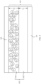
- FIG. 2 is a schematic diagram of a structure of a negative electrode plate 100 according to an embodiment of this application.
- the negative electrode plate 100 includes: a negative current collecting layer 101, and a lithiated binding layer 102 attached to an inner surface of the negative current collecting layer 101.
- a lithiation degree of a side of the lithiated binding layer 102 away from the inner surface is greater than a lithiation degree of a side of the lithiated binding layer 102 close to the inner surface.
- the negative current collecting layer 101 may be a current collector of a flat plate structure.
- the negative current collecting layer 101 may be made of metal foil, including but not limited to at least one of copper foil, aluminum foil, and titanium foil.
- the surface of the negative current collecting layer 101 may be coated with a functional coating, and the functional coating may be provided for improving conductivity of the negative electrode plate and improving safety of the negative electrode plate.
- the functional coating may include, but is not limited to, at least one of lithium iron phosphate, lithium manganese iron phosphate, lithium vanadium phosphate, lithium-manganese-rich base, artificial graphite, natural graphite, hard carbon, soft carbon, intermediate-phase carbon microspheres, carbon nanotubes, graphene, carbon fibers, vapor-grown carbon fibers, activated carbon, porous carbon, acetylene black, Ketjen black, conductive ink, thermally-expandable microspheres, polyethylene, polyamide, polybutadiene, ethylene ethyl acrylate, ethylene vinyl acetate copolymer, fluorinated ethylene propylene copolymer, polyethylene terephthalate, polypyrrole and derivatives thereof, polyvinylidene fluoride,
- the inner surface of the negative current collecting layer 101 may be coated with the lithiated binding layer 102.
- Active substances and a conductive agent may be mixed in the lithiated binding layer 102 to be used as an active substance layer of the negative electrode plate 100.
- the lithiated binding layer 102, the active substances, and the conductive agent may be mixed to form a slurry, and the inner surface of the negative current collecting layer 101 is coated with the slurry, for subsequent treatment.
- the lithiated binding layer 102 is formed by a binder.
- the binder may be at least one of polyvinylidene fluoride, polytetrafluoroethylene, polyamide, sodium carboxymethylcellulose, styrene butadiene rubber, polyacrylic acid, lithium carboxymethylcellulose, polyethylene oxide, and polyvinyl alcohol.
- the active substances may be at least one of a graphite material, a pure silicon material, a silicon oxygen material, and a silicon carbon material.
- the negative electrode plate 100 may be preferably a high-silicon negative electrode containing more than 20 wt% of silicon in percentage by mass.
- the conductive agent may be at least one of conductive metal powder, metal fibers, metal oxides, and other carbon-based conductive materials, such as copper powder, gold powder, nickel powder, copper fibers, stainless steel fibers, carbon black, carbon fibers, carbon nanotubes, and graphite.
- a separator 200 is provided on a surface of a side of the lithiated binding layer 102 away from the negative current collecting layer 101, and the separator 200 is provided for separating a positive electrode plate from the negative electrode plate 100, to avoid a short circuit caused by the contact between the positive electrode plate and the negative electrode plate 100.
- the separator 200 is not an internal structure of the negative electrode plate 100, and the separator 200 is only used in the embodiments of this application to describe a relative position of the internal structure of the negative electrode plate 100.
- the functional coating is provided between the negative current collecting layer 101 and the lithiated binding layer 102.
- the lithiated binding layer 102 may include lithiated binders of different lithiation degrees, for example, including a binder Li a -Binder of a lithiation degree a and a binder Li b -Binder of a lithiation degree b.
- Li a -Binder may be located in a region of the lithiated binding layer 102 close to the inner surface of the negative current collecting layer 101.
- Li b -Binder may be located in a region of the lithiated binding layer 102 away from the inner surface of the negative current collecting layer 101.
- the lithiation degree of Li b -Binder is greater than the lithiation degree of Li a -Binder.
- a and b meet the following relationship: 0 ⁇ a/b ⁇ 1.
- Li a -Binder indicates that a ratio of lithium ions to binder polymer repeating units is a:1.
- Li b -Binder indicates that a ratio of lithium ions to binder polymer repeating units is b:1.
- the lithiated binding layer 102 may include PAA binders of different lithiation degrees, for example, including a PAA binder Li a PAA of a lithiation degree a and a PAA binder Li b PAA of a lithiation degree b.
- PAA is a water-soluble polymer
- Li b PAA indicates that, for the PAA polymer molecules, a ratio of lithium ions to polymer repeating acrylic units is b:1.
- a region close to the inner surface of the negative current collecting layer 101 includes Li 0.2 PAA
- a region away from the inner surface of the negative current collecting layer 101 includes Li 0.5 PAA
- a region close to the inner surface of the negative current collecting layer 101 includes PAA
- a region away from the inner surface of the negative current collecting layer 101 includes LiPAA.
- the lithiated binding layer 102 has a gradient distribution of binders, and this gradient distribution may be a gradient distribution of lithiated binders of different lithiation degrees, such as Li 0.2 PAA and Li 0.5 PAA, or may be a gradient distribution of a lithiated binder and an unlithiated binder, such as PAA and LiPAA. Only PAA and LiPAA are used as an example in FIG. 2 .
- the lithiated binding layer 102 in the negative electrode plate 100 has a conductive gradient and a binding gradient through a gradient distribution of lithiation degrees in the lithiated binding layer 102.
- the lithiated binding layer 102 includes a first binding layer 1021 close to the inner surface of the negative current collecting layer 101 and a second binding layer 1022 away from the inner surface of the negative current collecting layer 101.
- a lithiation degree of the first binding layer 1021 is less than a lithiation degree of the second binding layer 1022, and the first binding layer 1021 and the second binding layer 1022 are obtained sequentially through coating on the inner surface of the negative current collecting layer 101.
- the lithiated binding layer 102 has two different lithiation degrees to form a lithiation degree gradient.
- the first binding layer 1021 has a first thickness h1
- the second binding layer 1022 has a second thickness h2
- the second thickness h2 and the first thickness h1 have a first ratio k
- the lithiated binding layer 102 formed based on this thickness relationship has an appropriate conductive gradient and binding gradient.
- the lithiation degree of the first binding layer 1021 may be greater than or equal to 0.
- the first binding layer 1021 may be an unlithiated binder or a partially lithiated binder.
- the first binding layer 1021 may be Li a PAA
- the second binding layer 1022 may be Li b PAA.
- the lithiated binding layer 102 has a gradient distribution of binders, and this gradient distribution may be a gradient distribution of two lithiated binders of different lithiation degrees, such as Li 0.2 PAA and Li 0.5 PAA, or may be a gradient distribution of a lithiated binder and an unlithiated binder, such as PAA and Li 0.5 PAA.
- the lithiated binding layer 102 in the negative electrode plate 100 has a conductive gradient and a binding gradient through a gradient distribution of lithiation degrees in the lithiated binding layer 102.
- the values of a and b in the foregoing embodiments are only used as examples for description.
- the values of a and b are not limited in the embodiments of this application.
- a is equal to 0 and b is equal to 1.
- the first binding layer 1021 is PAA, which is a binder that does not contain lithium ions and has a strong binding capability
- the second binding layer 1022 is LiPAA, which is a binder with a high lithiation degree and a strong conductive capability.
- FIG. 4 is a schematic diagram of a second concentration distribution of a negative electrode plate 100 according to an embodiment of this application.
- the lithiation degree of the lithiated binding layer 102 increases gradually in the direction of moving away from the inner surface of the negative current collecting layer 101, forming a structure with a gradient change in the lithiation degree.
- the lithiated binding layer 102 may include more structures of binding layers, such as a third binding layer 1023, ..., and an N th binding layer 102N (N ⁇ 2).
- the first binding layer 1021 to the N th binding layer 102N are obtained sequentially through coating on the inner surface of the negative current collecting layer 101 in the direction of moving away from the negative current collecting layer 101.
- the lithiated binding layer 102 may have multiple different lithiation degrees to form a lithiation degree gradient.
- the first binding layer 1021, the second binding layer 1022, the third binding layer 1023, ..., and the N th binding layer 102N may be sequentially Li a PAA, Li b PAA, Li c PAA, ..., and Li n PAA (0 ⁇ a ⁇ b ⁇ c ⁇ ... ⁇ n ⁇ 1).
- the lithiated binding layer 102 in the direction of moving away from the inner surface, the lithiated binding layer 102 has a gradually improved lithium-conducting capability and a gradually reduced adhesive force, so that the lithiated binding layer 102 has a conductive gradient and a binding gradient.
- the first binding layer 1021 to the N th binding layer that are of multiple different lithiation degrees may be obtained sequentially through coating, so that there are clear gradient boundaries.
- FIG. 5 is a schematic diagram of a third concentration distribution of a negative electrode plate 100 according to an embodiment of this application.
- the lithiation degree of the lithiated binding layer 102 increases gradually in the direction of moving away from the inner surface of the negative current collecting layer 101, forming a structure with lithium ions of a gradual concentration.
- the lithiated binding layer 102 includes two lithiated binders of different lithiation degrees, and the two lithiated binders of different lithiation degrees have different mixing ratios in the direction of moving away from the inner surface of the negative current collecting layer 101, so that the lithiation degree of the lithiated binding layer 102 increases gradually, forming a structure with lithium ions of a gradual concentration.
- the lithiated binding layer 102 may include two binders LiPAA and PAA of different lithiation degrees, the two binders are mixed and distributed in different ratios in the direction of moving away from the inner surface of the negative current collecting layer 101, and a mixing ratio of LiPAA to PAA increases gradually. If a thickness of the lithiated binding layer 102 is 100 ⁇ m, a ratio of LiPAA to PAA is 0.4-0.5 in a region of a thickness 80-100 ⁇ m, and a ratio of LiPAA to PAA is 0.3-0.4 in a region of a thickness 60-80 ⁇ m.
- LiPAA has a gradual concentration
- the gradual concentration of LiPAA provides a conductive gradient
- PAA has a gradual concentration
- the gradual concentration of PAA provides a binding gradient, so that the lithiated binding layer 102 has both the conductive gradient and the binding gradient.
- the lithiated binding layer of two different lithiation degrees may be obtained based on an electric-field inductive effect, and therefore has a gradual distribution in different mixing ratios with no clear gradient boundaries.
- the lithiated binding layer 102 includes multiple binders of different lithiation degrees, and the multiple binders of different lithiation degrees are mixed and distributed in different ratios in the direction of moving away from the inner surface of the negative current collecting layer 101.
- the lithiated binding layer 102 may include Li a PAA, Li b PAA, Li c PAA, ..., and Li n PAA (0 ⁇ a ⁇ b ⁇ c ⁇ ... ⁇ n ⁇ 1).
- Li a is equal to 0.2
- b is equal to 0.3
- c is equal to 0.4
- n is equal to 0.5
- Li 0.2 PAA, Li 0.3 PAA, Li 0.4 PAA, and Li 0.5 PAA are distributed sequentially in the lithiated binding layer 102 in the direction of moving away from the inner surface.
- the binders in the lithiated binding layer 102 are distributed in a gradual concentration.
- the lithiated binding layer 102 in the negative electrode plate 100 has a conductive gradient and a binding gradient through the distribution of lithiation degrees in the lithiated binding layer 102 in the gradual concentration.
- the lithiated binding layer 102 of multiple different lithiation degrees may be obtained based on an electric-field inductive effect.
- an electric field when an electric field is applied, lithium ions migrate under the action of the electric field in the direction of moving away from the negative current collecting layer 101, to increase the lithiation degree gradually.
- the lithiated binding layer 102 in the direction of moving away from the inner surface, has a gradually improved lithium-conducting capability and a gradually reduced adhesive force.
- the lithiated binding layer 102 has a gradual conductive capability and a gradual binding capability, with no clear gradient boundaries.
- lithium-ion conductivity of the side of the lithiated binding layer 102 away from the inner surface of the negative current collecting layer 100 is greater than lithium-ion conductivity of the side of the lithiated binding layer 102 close to the inner surface.
- lithium-ion conductivity ⁇ 2 of the second binding layer 1022 is greater than lithium-ion conductivity ⁇ 1 of the first binding layer 1021, that is, ⁇ 2 and ⁇ 1 meet the following relationship: ⁇ 2/ ⁇ 1 > 1.
- the negative electrode plate 100 shown in the schematic diagram of the first gradient distribution is only used as an example for description.
- lithium-ion conductivity ⁇ 2 of the side of the lithiated binding layer 102 away from the inner surface is greater than lithium-ion conductivity ⁇ 1 of the side of the lithiated binding layer 102 close to the inner surface.
- ⁇ 2 and ⁇ 1 meet the following relationship: ⁇ 2/ ⁇ 1 > 1.
- an adhesive force of the side of the lithiated binding layer 102 away from the inner surface is less than an adhesive force of the side of the lithiated binding layer 102 close to the inner surface.
- an adhesive force s2 of the second binding layer 1022 is less than an adhesive force s1 of the first binding layer 1021, that is, s2 and s1 meet the following relationship: s2/s1 ⁇ 1.
- the negative electrode plate 100 shown in the schematic diagram of the first gradient distribution is only used as an example for description.
- an adhesive force s2 of the side of the lithiated binding layer 102 away from the inner surface is less than an adhesive force s1 of the side of the lithiated binding layer 102 close to the inner surface.
- s2 and s1 meet the following relationship: s2/s1 ⁇ 1.
- the lithiated binding layer 102 in the negative electrode plate 100 has a conductive gradient and a binding gradient through a gradient distribution of lithiation degrees in the lithiated binding layer 102.
- the problem of detachment in a negative electrode plate with a conventional binder can be resolved, a rate of battery kinetics is increased, and initial coulombic efficiency of a lithium-ion battery is increased, increasing capacity of a lithium-ion battery.
- This application provides a method for preparing the negative electrode plate 100.
- the method for preparing the negative electrode plate 100 in the embodiments of this application includes step S100.
- Step S100 Coat an inner surface of a negative current collecting layer 101 with a lithiated binding layer 102 to obtain the negative electrode plate 100, where a lithiation degree of a side of the lithiated binding layer 102 away from the inner surface is greater than a lithiation degree of a side of the lithiated binding layer 102 close to the inner surface.
- FIG. 6 is a flowchart of a method for preparing a negative electrode plate 100 according to an embodiment of this application. As shown in FIG. 6 , step 100 may be further implemented through the following steps S101 and S102.
- Step S101 Coat the inner surface of the negative current collecting layer 101 with a first binding layer 1021.
- the first binding layer 1021 may be obtained by mixing a binder, active substances, and a conductive agent to form a slurry and coating the inner surface of the negative current collecting layer 101 with the slurry.
- the active substances and the conductive agent are not described in the embodiments of this application.
- the lithiation degree of the first binding layer 1021 may be greater than or equal to 0.
- the first binding layer 1021 may be an unlithiated binder or a partially lithiated binder.
- the first binding layer 1021 may be an unlithiated binder PAA.
- the first binding layer 1021 has a strong binding capability.
- the first binding layer 1021 may alternatively be a lithiated binder of another lithiation degree, for example, Li 0.2 PAA.
- the lithiation degree of the first binding layer 1021 is not limited in the embodiments of this application.
- Step S102 Coat a side of the first binding layer 1021 away from the inner surface of the negative current collecting layer 101 with a second binding layer 1022 to obtain the lithiated binding layer 102 including the first binding layer 1021 and the second binding layer 1022.
- a lithiation degree of the first binding layer 1021 is less than a lithiation degree of the second binding layer 1022.
- the second binding layer 1022 is LiPAA.
- the second binding layer 1022 has a strong conductive capability.
- the first binding layer 1021 has a first thickness h1
- the second binding layer 1022 has a second thickness h2
- the second thickness h2 and the first thickness h1 have a first ratio k
- the lithiated binding layer 102 formed based on this thickness relationship has an appropriate conductive gradient and binding gradient.
- the negative electrode plate 100 is prepared through layered coating.
- the negative current collecting layer 101 is coated directly with two binders of different lithiation degrees in layers, which can quickly form a conductive gradient and a binding gradient in the lithiated binding layer 102.
- the lithiated binding layer 102 may include more structures of binding layers, such as a third binding layer 1023, a fourth binding layer 1024, ..., and an N th binding layer 102N.
- the third binding layer 1023 to the N th binding layer 102N are provided between the first binding layer 1021 and the second binding layer 1022.
- the lithiated binding layer 102 may have multiple different lithiation degrees to form a lithiation degree gradient.
- the negative electrode plate 100 may be prepared through layered coating.
- the inner surface of the negative current collecting layer 101 is coated with the first binding layer 1021 to the N th binding layer that are of multiple different lithiation degrees sequentially.
- there are clear gradient boundaries among the first binding layer 1021 to the N th binding layer which can quickly form a conductive gradient and a binding gradient in the lithiated binding layer 102.
- the structure in the foregoing embodiments may be, but is not limited to, prepared through layered coating, or may be prepared based on an electric-field inductive effect.
- FIG. 7 is a flowchart of another method for preparing a negative electrode plate 100 according to an embodiment of this application.
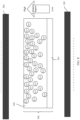
- FIG. 8 is a schematic diagram of an electric-field inductive effect according to an embodiment of this application. As shown in FIG. 7 and FIG. 8 , step S100 is implemented through the following steps S201 to S204.
- Step S201 Coat the inner surface of the negative current collecting layer 101 with the lithiated binding layer 102 to obtain a to-be-treated negative electrode plate, where the lithiated binding layer 102 is obtained by mixing binders of different lithiation degrees.
- the lithiated binding layer 102 is obtained by mixing two binders of different lithiation degrees, for example, obtained by mixing LiPAA and PAA.
- a mixing ratio of the two binders of different lithiation degrees is not limited in the embodiments of this application.
- the lithiated binding layer 102 is obtained by mixing multiple binders of different lithiation degrees, for example, the lithiated binding layer 102 is obtained by mixing Li a PAA, Li b PAA, Li c PAA, ..., and Li n PAA (0 ⁇ a ⁇ b ⁇ c ⁇ ... ⁇ n ⁇ 1).
- a mixing ratio of the multiple binders of different lithiation degrees is not limited in the embodiments of this application.
- Step S202 Place the to-be-treated negative electrode plate between a positive plate 301 and a negative plate 302 of a planar electrode, where the negative current collecting layer 101 is oriented toward the positive plate 301 of the planar electrode, and the lithiated binding layer 102 is oriented toward the negative plate 302 of the planar electrode.
- the lithium ions can migrate toward the negative plate 302 of the planar electrode.
- the negative current collecting layer 101 is oriented toward the positive plate 301 of the planar electrode
- the lithiated binding layer 102 is oriented toward the negative plate 302 of the planar electrode.
- Step S203 Apply an electric field between the positive plate 301 and the negative plate 302 of the planar electrode, for lithium ions in the lithiated binding layer 102 to flow close to the negative plate 302 under the electric field, so that the lithiation degree of the side of the lithiated binding layer 102 away from the inner surface of the negative current collecting layer 101 is greater than the lithiation degree of the side of the lithiated binding layer close to the inner surface of the negative current collecting layer 101.
- the lithium ions can complete the migration toward the negative plate 302, forming a conductive gradient and a binding gradient in the lithiated binding layer 102.
- the lithiated binding layer 102 is obtained by mixing two binders of different lithiation degrees, the two binders are mixed and distributed in different ratios in the direction of moving away from the inner surface of the negative current collecting layer 101, and a mixing ratio of LiPAA to PAA increases gradually.
- the lithium ions can complete the migration toward the negative plate 302, so that in the direction of moving away from the negative current collecting layer 101, the lithiation degree increases gradually, the lithium-conducting capability of the lithiated binding layer 102 increases gradually, and the binding capability decreases gradually, forming a conductive gradient and a binding gradient.
- the lithiated binding layer 102 is obtained by mixing multiple binders of different lithiation degrees, and the multiple binders are mixed and distributed in different ratios in the direction of moving away from the inner surface of the negative current collecting layer 101.
- the lithiation degree increases gradually, the lithium-conducting capability of the lithiated binding layer 102 increases gradually, and the binding capability decreases gradually, forming a conductive gradient and a binding gradient.
- a distance between the positive plate 301 and the negative plate 302 of the planar electrode is greater than or equal to 1 cm and less than or equal to 10 cm.
- a voltage of the electric field is greater than or equal to 0.1 kV and less than or equal to 10 kV.
- Step S204 Place the to-be-treated negative electrode plate and the planar electrode in an oven for drying to obtain the negative electrode plate 100.
- the binder in the lithiated binding layer 102 is a slurry, which needs to be dried to obtain the negative electrode plate 100.
- a drying temperature of the oven is 110°C.
- drying temperature in the embodiments of this application is only used as an example for description, and may be adjusted as required in a specific implementation process.
- the negative electrode plate 100 is prepared based on an electric-field inductive effect. A gradient distribution of the lithiation degree is completed in this process. It needs to be noted herein that, the mechanism of migration of lithium ions in this embodiment is different from a mechanism of migration of lithium ions in an electrolyte.
- FIG. 9 is a schematic diagram of a migration mechanism of lithium ions in an electrolyte.
- the electrolyte is a solvent-free polymer polyethylene oxide (PEO)
- PEO polymer polyethylene oxide
- the complexation is carried out through coordinate bonding of positive ions or neutral molecules with a specific quantity of nuclei or negative ions. Stable complicated ions or molecules are referred to as complex ions.
- a compound containing complex ions is referred to as a complex.
- a reaction in which complex ions or a complex is formed is the complexation.
- the region A in FIG. 9 shows a specific process of "decomplexation-recomplexation" between the lithium ions and the polymer.
- the electrolyte contains a complex formed from the lithium ions and the polymer. Lithium ions (Li + ) in the complex undergo the decomplexation with the surrounding oxygen atoms O1, O2, O3, O4, and O1' as in a first process 300 to be removed from these oxygen atoms, and are then combined with O4, O5, O2', and O3' to undergo the recomplexation as in a second process 400.
- O5, O2', and O3' in the first process 300 are atoms that do not react with Li +
- O1, O2, O3, and O1' in the second process 400 are atoms that do not react with Li + .
- the mixture can implement conversion through thermal motion between lithium ions and protons, and lithium ions undergo orientational motion due to electrostatic attraction when an electric field is applied, and lithium ions exchange with protons through free chain segmental relaxation of the polymer to implement orientational migration of the lithium ions.
- a gradient distribution of LiPAA and PAA is implemented based on the electric-field inductive effect.
- a gradual gradient formed in LiPAA provides a conductive gradient
- a gradual gradient formed in PAA provides a binding gradient, so that the lithiated binding layer 102 has both the conductive gradient and the binding gradient.
- the conductive gradient improves lithium-ion transport performance, and the binding gradient resolves the problem of detachment, improving cycle stability of a lithium-ion battery.
- the lithiated binding layer in the negative electrode plate 100 has a conductive gradient and a binding gradient through a gradient distribution of lithiation degrees in the lithiated binding layer 102.
- an adhesive force in the lithiated binding layer 100 is increased, which can resolve the problem of detachment in the negative electrode plate 100, and a lithium-conducting capability in the lithiated binding layer 102 is improved, which can resolve the problem of a decrease in initial coulombic efficiency, thereby promoting an increase in energy density of a lithium-ion battery.
- the lithium-ion battery includes a positive electrode plate, a separator 200, and the negative electrode plate 100 in the foregoing embodiments.
- the separator 200 is located between the positive electrode plate and the negative electrode plate 100. In this way, the separator 200 can separate the positive electrode plate from the negative electrode plate 100, avoiding a short circuit caused by the contact between the positive electrode plate and the negative electrode plate 100.
- the lithium-ion battery further includes a housing, and the housing is filled with an electrolyte.
- the positive electrode plate, the separator 200, and the negative electrode plate 100 are provided inside the housing.
- the positive electrode plate, the separator 200, and the negative electrode plate 100 are immersed in the electrolyte.
- the electrolyte includes a solvent and a lithium salt.
- the solvent is at least one of ethylene carbonate, propylene carbonate, dimethyl carbonate, ethyl methyl carbonate, propyl propionate, and ethyl propionate.
- the lithium salt may be at least one of lithium hexafluorophosphate, lithium bis(oxalate) borate, lithium difluoro(oxalato)borate, lithium bisdifluorosulfonimide, and lithium bis(trifluoromethanesulphonyl)imide.
- the positive electrode plate may include a positive-electrode current collector and a positive-electrode active substance layer attached to a surface of the positive-electrode current collector.
- Active substances in the positive-electrode active substance layer may be at least one of lithium cobaltate, lithium iron phosphate, sodium iron phosphate, lithium manganese iron phosphate, lithium vanadium phosphate, sodium vanadium phosphate, lithium vanadyl phosphate, sodium vanadyl phosphate, lithium vanadate, lithium nickelate, lithium manganate, lithium nickel cobalt manganate, lithium nickel cobalt aluminate, lithium titanate, and lithium-manganese-rich materials.
- the lithiated binding layer in the negative electrode plate 100 has a conductive gradient and a binding gradient through a gradient distribution of lithiation degrees in the negative electrode plate 100.
- an adhesive force between the lithiated binding layer and the current collector is increased, which can resolve the problem of detachment in the negative electrode plate, and a lithium-conducting capability of the surface of the lithiated binding layer is improved, and a rate of interface lithium-conducting kinetics is increased, which can resolve the problem of a decrease in initial coulombic efficiency, thereby promoting an increase in energy density of the lithium-ion battery.
- the lithium-ion battery in the embodiments of this application has high energy density.
- the electronic device includes an electrical element and the lithium-ion battery according to the foregoing embodiment.
- the lithium-ion battery may be electrically connected to the electrical element.
- a type of the electronic device includes, but is not limited to, a mobile phone, a tablet computer, a notebook computer, a large-screen device (such as a smart TV or a smart screen), a personal computer (persona1computer, PC), a handheld computer, a netbook, a personal digital assistant (personal digital assistant, PDA), a wearable electronic device, an onboard device, and a virtual reality device.
- the electronic device may also be a wireless charging electric vehicle, a wireless charging household appliance, an unmanned aircraft, and another electronic product.
- the lithiated binding layer in the negative electrode plate 100 has a conductive gradient and a binding gradient through a gradient distribution of lithiation degrees in the negative electrode plate 100 of the lithium-ion battery.
- an adhesive force in the lithiated binding layer is increased, which can resolve the problem of detachment in the negative electrode plate, and a lithium-conducting capability in the lithiated binding layer is improved, which can resolve the problem of a decrease in initial coulombic efficiency, thereby promoting an increase in energy density of a lithium-ion battery.
- the electronic device in the embodiments of this application has a long battery life.
- the term “include”, “comprise”, or any other variant thereof is intended to cover a non-exclusive inclusion, so that a process, a method, an object, or a device that includes a series of elements not only includes such elements, but also includes other elements not expressly listed, or further includes elements inherent to such process, method, object, or device.
Landscapes
- Chemical & Material Sciences (AREA)
- Chemical Kinetics & Catalysis (AREA)
- Electrochemistry (AREA)
- General Chemical & Material Sciences (AREA)
- Engineering & Computer Science (AREA)
- Manufacturing & Machinery (AREA)
- Materials Engineering (AREA)
- Physics & Mathematics (AREA)
- Composite Materials (AREA)
- Condensed Matter Physics & Semiconductors (AREA)
- Dispersion Chemistry (AREA)
- General Physics & Mathematics (AREA)
- Inorganic Chemistry (AREA)
- Thermal Sciences (AREA)
- Battery Electrode And Active Subsutance (AREA)
Abstract
Description
- This application claims priority to
Chinese Patent Application No. 202310073885.7, filed with the China National Intellectual Property Administration on January 13, 2023 - Embodiments of this application relate to the field of lithium-ion battery technologies, and in particular, to a negative electrode plate, a method for preparing a negative electrode plate, and a lithium-ion battery.
- With the development of lithium-ion batteries, a negative electrode plate of a lithium-ion battery has evolved from a carbon material to a silicon negative electrode material. The silicon negative electrode material has high capacity per gram, high volumetric specific capacity, appropriate lithium intercalation potentials, and low costs, which can increase energy density of the system of the lithium-ion battery. However, the silicon negative electrode material undergoes tremendous volume deformation during repeated deintercalation of lithium ions, causing the rupture of silicon particles and the collapse of the structure of the negative electrode plate, consequently resulting in a decrease in the capacity and cycle performance of the lithium-ion battery.
- A binder can be used to stabilize the structure of the silicon negative electrode material. The binder needs to provide a good lithium-conducting capability, low ohmic resistance, and a strong binding capability. In this case, the lithium-ion battery does not undergo detachment and has an excellent capability of fast charging and discharging. However, a conventional binder reacts with lithium ions in an electrolyte, resulting in a decrease in the lithium-conducting capability and initial coulombic efficiency of the lithium-ion battery, while a lithiated binder can improve the lithium-conducting capability of the battery, but has a low binding capability, leading to detachment in the negative electrode plate. Therefore, the negative electrode plate with the conventional binder cannot have both a good lithium-conducting capability and a strong binding capability.
- Embodiments of this application provide a negative electrode plate, a method for preparing a negative electrode plate, and a lithium-ion battery, which can resolve the problem of detachment in a negative electrode plate with a conventional binder, and increase initial coulombic efficiency of a lithium-ion battery, increasing capacity of the lithium-ion battery.
- According to a first aspect, this application provides a negative electrode plate, including: a negative current collecting layer; and a lithiated binding layer, attached to an inner surface of the negative current collecting layer, where a lithiation degree of a side of the lithiated binding layer away from the inner surface is greater than a lithiation degree of a side of the lithiated binding layer close to the inner surface.
- The lithiated binding layer in the negative electrode plate according to this application has a conductive gradient and a binding gradient through a gradient distribution of lithiation degrees in the lithiated binding layer. In this case, an adhesive force between the lithiated binding layer and the negative current collecting layer is increased, which can resolve the problem of detachment in the negative electrode plate, and a lithium-conducting capability of the surface of the lithiated binding layer is improved, and a rate of interface kinetics is increased, which can resolve the problem of a decrease in initial coulombic efficiency, thereby promoting an increase in energy density of a lithium-ion battery.
- In an implementation, a lithiation degree of the lithiated binding layer increases gradually in the direction of moving away from the inner surface; and the lithiated binding layer is obtained based on an electric-field inductive effect. By using this implementation, the lithiation degree of the lithiated binding layer increases gradually in the direction of moving away from the inner surface based on the electric-field inductive effect, so that the lithiated binding layer in the negative electrode plate has a conductive gradient and a binding gradient. In this case, an adhesive force between the lithiated binding layer and the negative current collecting layer is increased, which can resolve the problem of detachment in the negative electrode plate, and a lithium-conducting capability of the surface of the lithiated binding layer is improved, which can resolve the problem of a decrease in initial coulombic efficiency, thereby promoting an increase in energy density of a lithium-ion battery.
- In an implementation, the lithiated binding layer includes a first binding layer close to the inner surface and a second binding layer away from the inner surface; and a lithiation degree of the first binding layer is less than a lithiation degree of the second binding layer, and the first binding layer and the second binding layer are obtained sequentially through coating on the inner surface of the negative current collecting layer. By using this implementation, the lithiated binding layer has a conductive gradient and a binding gradient through layered coating. In this case, an adhesive force between the lithiated binding layer and the negative current collecting layer is increased, which can resolve the problem of detachment in the negative electrode plate, and a lithium-conducting capability of the surface of the lithiated binding layer is improved, which can resolve the problem of a decrease in initial coulombic efficiency, thereby promoting an increase in energy density of a lithium-ion battery.
- In an implementation, the first binding layer has a first thickness, the second binding layer has a second thickness, the second thickness and the first thickness have a first ratio, and the first ratio is greater than or equal to 0.2 and less than or equal to 5. By using this implementation, the lithiated binding layer formed in this ratio has an appropriate conductive gradient and binding gradient.
- In an implementation, the lithiation degree of the first binding layer is greater than or equal to 0. By using this implementation, the first binding layer may be an unlithiated binder or a partially lithiated binder. In this case, the formed lithiated binding layer has an appropriate conductive gradient and binding gradient.
- In an implementation, lithium-ion conductivity of the side of the lithiated binding layer away from the inner surface is greater than lithium-ion conductivity of the side of the lithiated binding layer close to the inner surface. By using this implementation, the formed lithiated binding layer has an appropriate conductive gradient.
- In an implementation, an adhesive force of the side of the lithiated binding layer away from the inner surface is less than an adhesive force of the side of the lithiated binding layer close to the inner surface. By using this implementation, the formed lithiated binding layer has an appropriate binding gradient.
- According to a second aspect, this application provides a method for preparing a negative electrode plate, including: coating an inner surface of a negative current collecting layer with a lithiated binding layer to obtain the negative electrode plate, where a lithiation degree of a side of the lithiated binding layer away from the inner surface is greater than a lithiation degree of a side of the lithiated binding layer close to the inner surface.
- By using the method for preparing the negative electrode plate in this application, the lithiated binding layer in the negative electrode plate has a conductive gradient and a binding gradient through a gradient distribution of lithiation degrees in the lithiated binding layer. In this case, an adhesive force between the lithiated binding layer and the negative current collecting layer is increased, which can resolve the problem of detachment in the negative electrode plate, and a lithium-conducting capability of the surface of the lithiated binding layer is improved, which can resolve the problem of a decrease in initial coulombic efficiency, thereby promoting an increase in energy density of a lithium-ion battery.
- In an implementation, the coating an inner surface of a negative current collecting layer with a lithiated binding layer to obtain the negative electrode plate includes: coating the inner surface with the lithiated binding layer to obtain a to-be-treated negative electrode plate, where the lithiated binding layer is obtained by mixing binders of different lithiation degrees; placing the to-be-treated negative electrode plate between a positive plate and a negative plate of a planar electrode, where the negative current collecting layer is oriented toward the positive plate of the planar electrode, and the lithiated binding layer is oriented toward the negative plate of the planar electrode; applying an electric field between the positive plate and the negative plate of the planar electrode, for lithium ions in the lithiated binding layer to flow close to the negative plate under the electric field, so that the lithiation degree of the side of the lithiated binding layer away from the inner surface is greater than the lithiation degree of the side of the lithiated binding layer close to the inner surface; and placing the to-be-treated negative electrode plate and the planar electrode in an oven for drying to obtain the negative electrode plate. By using this implementation, the lithiation degree of the lithiated binding layer increases gradually in the direction of moving away from the inner surface based on the electric-field inductive effect, so that the lithiated binding layer in the negative electrode plate has a conductive gradient and a binding gradient. In this case, an adhesive force between the lithiated binding layer and the negative current collecting layer is increased, which can resolve the problem of detachment in the negative electrode plate, and a lithium-conducting capability of the surface of the lithiated binding layer is improved, which can resolve the problem of a decrease in initial coulombic efficiency, thereby promoting an increase in energy density of a lithium-ion battery.
- In an implementation, a distance between the positive plate and the negative plate of the planar electrode is greater than or equal to 1 cm and less than or equal to 10 cm; and a voltage of the electric field is greater than or equal to 0.1 kV and less than or equal to 10 kV. By using this implementation, the lithiated binding layer formed based on appropriate electric field parameters has an appropriate conductive gradient and binding gradient.
- In an implementation, a drying temperature of the oven is greater than or equal to 70°C and less than or equal to 110°C. By using this implementation, the lithiated binding layer formed based on an appropriate drying temperature has an appropriate conductive gradient and binding gradient.
- In an implementation, the coating an inner surface of a negative current collecting layer with a lithiated binding layer to obtain the negative electrode plate includes: coating the inner surface with a first binding layer; and coating a side of the first binding layer away from the inner surface with a second binding layer to obtain the lithiated binding layer including the first binding layer and the second binding layer, where a lithiation degree of the first binding layer is less than a lithiation degree of the second binding layer. By using this implementation, the lithiated binding layer has a conductive gradient and a binding gradient through layered coating. In this case, an adhesive force between the lithiated binding layer and the negative current collecting layer is increased, which can resolve the problem of detachment in the negative electrode plate, and a lithium-conducting capability of the surface of the lithiated binding layer is improved, which can resolve the problem of a decrease in initial coulombic efficiency, thereby promoting an increase in energy density of a lithium-ion battery.
- In an implementation, the first binding layer has a first thickness, the second binding layer has a second thickness, the second thickness and the first thickness have a first ratio, and the first ratio is greater than or equal to 0.2 and less than or equal to 5. By using this implementation, the lithiated binding layer formed in this ratio has an appropriate conductive gradient and binding gradient.
- In an implementation, the lithiation degree of the first binding layer is greater than or equal to 0. By using this implementation, the first binding layer may be an unlithiated binder or a partially lithiated binder. In this case, the formed lithiated binding layer has an appropriate conductive gradient and binding gradient.
- According to a third aspect, this application provides a lithium-ion battery, including: a positive electrode plate, a separator, and the negative electrode plate according to the first aspect and the implementations thereof, where the separator is located between the positive electrode plate and the negative electrode plate.
- To describe the technical solutions of the embodiments of this application more clearly, the following briefly describes the accompanying drawings required in the embodiments. Apparently, a person of ordinary skill in the art may further derive other drawings from these accompanying drawings without creative efforts.
-
FIG. 1 is a schematic diagram of a structure of a negative electrode plate of a lithium-ion battery; -
FIG. 2 is a schematic diagram of a structure of a negative electrode plate according to an embodiment of this application; -
FIG. 3 is a schematic diagram of a first concentration distribution of a negative electrode plate according to an embodiment of this application; -
FIG. 4 is a schematic diagram of a second concentration distribution of a negative electrode plate according to an embodiment of this application; -
FIG. 5 is a schematic diagram of a third concentration distribution of a negative electrode plate according to an embodiment of this application; -
FIG. 6 is a flowchart of a method for preparing a negative electrode plate according to an embodiment of this application; -
FIG. 7 is a schematic diagram of an electric-field inductive effect according to an embodiment of this application; -
FIG. 8 is a flowchart of another method for preparing a negative electrode plate according to an embodiment of this application; and -
FIG. 9 is a schematic diagram of a migration mechanism of lithium ions in an electrolyte. - The following clearly describes the technical solutions of the embodiments of this application with reference to the accompanying drawings in the embodiments of this application.
- In descriptions of this application, unless otherwise specified, "/" means "or". For example, A/B may indicate A or B. In this specification, "and/or" describes only an association relationship for describing associated objects and indicates that three relationships may exist. For example, A and/or B may indicate the following three cases: Only A exists, both A and B exist, and only B exists. In addition, "at least one" means one or more, and "a plurality of" means two or more. Terms such as "first" and "second" do not limit a quantity and an execution sequence, and the terms such as "first" and "second" do not indicate a definite difference.
- It needs to be noted that, in this application, the word such as "example" or "for example" is used to indicate giving an example, an illustration, or a description. Any embodiment or design scheme described as an "example" or "for example" in this application should not be explained as being more preferred or having more advantages than another embodiment or design scheme. Exactly, use of the word such as "example" or "for example" is intended to present a related concept in a specific manner.
- Terms used in implementations of this application are only used for explaining the specific embodiments of this application, but are not intended to limit this application. The embodiments of this application are described in detail below with reference to the accompanying drawings.
- An electronic device in use usually requires a power supply device for power supply. Currently, various electronic devices usually use a rechargeable battery (rechargeable battery), that is, a battery that is reusable after discharge through recharging to activate active substances, as a power supply device.
- A lithium-ion battery is a typical rechargeable battery, which works mainly relying on the movement of lithium ions (Li+) between a positive electrode and a negative electrode of the battery. During charging and discharging of the battery, lithium ions move between the two electrodes for intercalation and deintercalation. During charging, lithium ions are deintercalated from the positive electrode and intercalated into the negative electrode through an electrolyte, and then the negative electrode is in a lithium-rich state. The opposite is true for discharging.
- With the development of lithium-ion batteries, a negative electrode plate of a lithium-ion battery has evolved from a carbon material to a silicon negative electrode material. The silicon negative electrode material has high capacity per gram, high volumetric specific capacity, appropriate lithium intercalation potentials, and low costs, which can increase energy density of the system of the lithium-ion battery. However, the silicon negative electrode material undergoes tremendous volume deformation during repeated deintercalation of lithium ions, causing the rupture of silicon particles and the collapse of the structure of the negative electrode plate, consequently resulting in a decrease in the capacity and cycle performance of the lithium-ion battery.
-
FIG. 1 is a schematic diagram of a structure of anegative electrode plate 10 of a lithium-ion battery. As shown inFIG. 1 , thenegative electrode plate 10 may include acurrent collector 11 and a negative-electrodeactive substance layer 12 attached to an inner surface of thecurrent collector 11. Thecurrent collector 11 may be made of metal foil, such as copper foil or aluminum foil, for collecting currents generated byactive substances 121 in the negative-electrodeactive substance layer 12, to form a larger current for outputting. The negative-electrodeactive substance layer 12 may include theactive substances 121, a conductive agent (not shown inFIG. 1 ), and abinder 122, for increasing the energy density of the system of thenegative electrode plate 10. Theactive substances 121 may be at least one of a graphite material, a pure silicon material, a silicon oxygen material, and a silicon carbon material. Thenegative electrode plate 10 may be preferably a high-silicon negative electrode containing more than 20 wt% of silicon in percentage by mass (wt%). The conductive agent may be at least one of conductive metal powder, metal fibers, metal oxides, and other carbon-based conductive materials, such as copper powder, gold powder, nickel powder, copper fibers, stainless steel fibers, carbon black, carbon fibers, carbon nanotubes, and graphite. Thebinder 122 may be at least one of polyvinylidene fluoride, polytetrafluoroethylene, polyamide, sodium carboxymethylcellulose, styrene butadiene rubber, polyacrylic acid, lithium carboxymethylcellulose, polyethylene oxide, and polyvinyl alcohol. Thenegative electrode plate 10 in this application may further include another structure, for example, a functional coating (not shown inFIG. 1 ) coated between thecurrent collector 11 and the negative-electrodeactive substance layer 12. The functional coating may be provided for improving conductivity of the negative electrode plate. Other structures in the negative-electrodeactive substance layer 12 are not described in this application. - Further, as shown in
FIG. 1 , aseparator 20 is provided on a surface of a side of the negative-electrodeactive substance layer 12 away from thecurrent collector 11, and theseparator 20 is provided for separating a positive electrode plate from thenegative electrode plate 10, to avoid a short circuit caused by the contact between the positive electrode plate and thenegative electrode plate 10. It needs to be noted herein that, theseparator 20 is not an internal structure of thenegative electrode plate 10, and theseparator 20 is only used in the embodiments of this application to describe a relative position of the internal structure of thenegative electrode plate 10. - The
binder 122 may be a polymer compound for binding theactive substances 121 to thecurrent collector 11, which can bind theactive substances 121 and maintain the activity of theactive substances 121, and enhance the electronic contact between theactive substances 121 and the conductive agent and the electronic contact between theactive substances 121 and thecurrent collector 11. In this way, thebinder 122 can stabilize the structure of thenegative electrode plate 10. When thenegative electrode plate 10 is in the process of charging and discharging, thebinder 122 can buffer volume expansion/contraction of thenegative electrode plate 10, thereby preventing the collapse of the structure of thenegative electrode plate 10. - Using an example in which the
binder 122 is polyacrylic acid (PAA), PAA contains many carboxyl groups, which can form strong hydrogen bonding or direct bonding with functional groups on the surface of theactive substances 121. The bonding enhances the binding force between theactive substances 121 and the conductive agent and the binding force between theactive substances 121 and thecurrent collector 11, improving cycle performance of the silicon negative electrode material. - However, although PAA has a good binding force, there are still some problems in the use of this type of
binder 122. According to a first aspect, PAA has an average lithium-conducting capability and has no low ohmic resistance, which affects a capability of fast charging and discharging of a lithium-ion battery. According to a second aspect, carboxyl groups of PAA react with lithium ions in an electrolyte, for example, Li+ reacts with PAA to form LiPAA, and this reaction reduces initial coulombic efficiency of thenegative electrode plate 100. It needs to be noted herein that, the initial coulombic efficiency is an index for quantifying performance of a negative electrode plate of a lithium-ion battery, and is a ratio of discharge capacity to charge capacity in an initial charge-discharge cycle of the lithium-ion battery. In the process of initial charging and discharging, the coulombic efficiency usually fails to reach 100%, and there is a part of irreversible discharge capacity for the lithium-ion battery. This part of capacity affects the assembly of the lithium-ion battery. Low initial coulombic efficiency indicates a severe side reaction, which directly reduces the capacity of the lithium-ion battery and shortens the cycle life of the lithium-ion battery. - Using an example in which the
binder 122 is a lithiated binder (for example, lithiated polyacrylic acid (LiPAA)), as LiPAA does not react with lithium ions in an electrolyte, this type ofbinder 122 does not affect the initial coulombic efficiency of thenegative electrode plate 10. However, this type ofbinder 122 does not contain many carboxyl groups, which cannot form strong hydrogen bonding or direct bonding with functional groups on the surface of theactive substances 121. In this case, this type ofbinder 122 has a binding force significantly lower than PAA, which cannot provide a good binding force between theactive substances 121 and the conductive agent and a good binding force between theactive substances 121 and thecurrent collector 11, easily leading to detachment between thecurrent collector 11 and the negative-electrodeactive substance layer 12. - In conclusion, if the
binder 122 is an unlithiated binder, the impedance of the binder is high, and the initial coulombic efficiency is low; or if thebinder 122 is a lithiated binder, there is a problem of detachment in thenegative electrode plate 10. - To resolve the foregoing problems, an embodiment of this application provides a
negative electrode plate 100. -
FIG. 2 is a schematic diagram of a structure of anegative electrode plate 100 according to an embodiment of this application. As shown inFIG. 2 , thenegative electrode plate 100 includes: a negativecurrent collecting layer 101, and a lithiatedbinding layer 102 attached to an inner surface of the negativecurrent collecting layer 101. A lithiation degree of a side of the lithiatedbinding layer 102 away from the inner surface is greater than a lithiation degree of a side of the lithiatedbinding layer 102 close to the inner surface. - The negative
current collecting layer 101 may be a current collector of a flat plate structure. The negativecurrent collecting layer 101 may be made of metal foil, including but not limited to at least one of copper foil, aluminum foil, and titanium foil. - In some embodiments, the surface of the negative
current collecting layer 101 may be coated with a functional coating, and the functional coating may be provided for improving conductivity of the negative electrode plate and improving safety of the negative electrode plate. The functional coating may include, but is not limited to, at least one of lithium iron phosphate, lithium manganese iron phosphate, lithium vanadium phosphate, lithium-manganese-rich base, artificial graphite, natural graphite, hard carbon, soft carbon, intermediate-phase carbon microspheres, carbon nanotubes, graphene, carbon fibers, vapor-grown carbon fibers, activated carbon, porous carbon, acetylene black, Ketjen black, conductive ink, thermally-expandable microspheres, polyethylene, polyamide, polybutadiene, ethylene ethyl acrylate, ethylene vinyl acetate copolymer, fluorinated ethylene propylene copolymer, polyethylene terephthalate, polypyrrole and derivatives thereof, polyvinylidene fluoride, polytetrafluoroethylene, polyamide, sodium carboxymethylcellulose, and styrene butadiene rubber. The inner surface of the negativecurrent collecting layer 101 may be coated with the lithiatedbinding layer 102. Active substances and a conductive agent may be mixed in the lithiatedbinding layer 102 to be used as an active substance layer of thenegative electrode plate 100. For example, the lithiatedbinding layer 102, the active substances, and the conductive agent may be mixed to form a slurry, and the inner surface of the negativecurrent collecting layer 101 is coated with the slurry, for subsequent treatment. - The lithiated
binding layer 102 is formed by a binder. The binder may be at least one of polyvinylidene fluoride, polytetrafluoroethylene, polyamide, sodium carboxymethylcellulose, styrene butadiene rubber, polyacrylic acid, lithium carboxymethylcellulose, polyethylene oxide, and polyvinyl alcohol. The active substances may be at least one of a graphite material, a pure silicon material, a silicon oxygen material, and a silicon carbon material. Thenegative electrode plate 100 may be preferably a high-silicon negative electrode containing more than 20 wt% of silicon in percentage by mass. The conductive agent may be at least one of conductive metal powder, metal fibers, metal oxides, and other carbon-based conductive materials, such as copper powder, gold powder, nickel powder, copper fibers, stainless steel fibers, carbon black, carbon fibers, carbon nanotubes, and graphite. - The embodiments of this application only describe a specific structure of the lithiated
binding layer 102, but do not describe the active substances and the conductive agent. - Further, as shown in
FIG. 2 , aseparator 200 is provided on a surface of a side of the lithiatedbinding layer 102 away from the negativecurrent collecting layer 101, and theseparator 200 is provided for separating a positive electrode plate from thenegative electrode plate 100, to avoid a short circuit caused by the contact between the positive electrode plate and thenegative electrode plate 100. It needs to be noted herein that, theseparator 200 is not an internal structure of thenegative electrode plate 100, and theseparator 200 is only used in the embodiments of this application to describe a relative position of the internal structure of thenegative electrode plate 100. - It needs to be noted herein that, if the surface of the negative
current collecting layer 101 is coated with a functional coating, the functional coating is provided between the negativecurrent collecting layer 101 and the lithiatedbinding layer 102. - In some embodiments, the lithiated
binding layer 102 may include lithiated binders of different lithiation degrees, for example, including a binder Lia-Binder of a lithiation degree a and a binder Lib-Binder of a lithiation degree b. Lia-Binder may be located in a region of the lithiatedbinding layer 102 close to the inner surface of the negativecurrent collecting layer 101. Lib-Binder may be located in a region of the lithiatedbinding layer 102 away from the inner surface of the negativecurrent collecting layer 101. The lithiation degree of Lib-Binder is greater than the lithiation degree of Lia-Binder. In other words, a and b meet the following relationship: 0 ≤ a/b < 1. Lia-Binder indicates that a ratio of lithium ions to binder polymer repeating units is a:1. Correspondingly, Lib-Binder indicates that a ratio of lithium ions to binder polymer repeating units is b:1. - For example, the lithiated
binding layer 102 may include PAA binders of different lithiation degrees, for example, including a PAA binder LiaPAA of a lithiation degree a and a PAA binder LibPAA of a lithiation degree b. PAA is a water-soluble polymer, and LibPAA indicates that, for the PAA polymer molecules, a ratio of lithium ions to polymer repeating acrylic units is b:1. - For example, when a is equal to 0.2 and b is equal to 0.5, in the lithiated
binding layer 102, a region close to the inner surface of the negativecurrent collecting layer 101 includes Li0.2PAA, and a region away from the inner surface of the negativecurrent collecting layer 101 includes Li0.5PAA. When a is equal to 0 and b is equal to 1, in the lithiatedbinding layer 102, a region close to the inner surface of the negativecurrent collecting layer 101 includes PAA, and a region away from the inner surface of the negativecurrent collecting layer 101 includes LiPAA. In other words, the lithiatedbinding layer 102 has a gradient distribution of binders, and this gradient distribution may be a gradient distribution of lithiated binders of different lithiation degrees, such as Li0.2PAA and Li0.5PAA, or may be a gradient distribution of a lithiated binder and an unlithiated binder, such as PAA and LiPAA. Only PAA and LiPAA are used as an example inFIG. 2 . In this way, the lithiatedbinding layer 102 in thenegative electrode plate 100 has a conductive gradient and a binding gradient through a gradient distribution of lithiation degrees in the lithiatedbinding layer 102.FIG. 3 is a schematic diagram of a first concentration distribution of anegative electrode plate 100 according to an embodiment of this application. As shown inFIG. 3 , in some embodiments, the lithiatedbinding layer 102 includes a firstbinding layer 1021 close to the inner surface of the negativecurrent collecting layer 101 and a secondbinding layer 1022 away from the inner surface of the negativecurrent collecting layer 101. A lithiation degree of the firstbinding layer 1021 is less than a lithiation degree of the secondbinding layer 1022, and the firstbinding layer 1021 and the secondbinding layer 1022 are obtained sequentially through coating on the inner surface of the negativecurrent collecting layer 101. In this case, the lithiatedbinding layer 102 has two different lithiation degrees to form a lithiation degree gradient. - In some embodiments, the first
binding layer 1021 has a first thickness h1, the secondbinding layer 1022 has a second thickness h2, the second thickness h2 and the first thickness h1 have a first ratio k, and the first ratio k is greater than or equal to 0.2 and less than or equal to 5, that is, h1, h2, and k meet the following relationship: h2/h1 = k (kε[0.2,5]). In this way, the lithiatedbinding layer 102 formed based on this thickness relationship has an appropriate conductive gradient and binding gradient. - In some embodiments, the lithiation degree of the first
binding layer 1021 may be greater than or equal to 0. In other words, the firstbinding layer 1021 may be an unlithiated binder or a partially lithiated binder. - The first
binding layer 1021 may be LiaPAA, and the secondbinding layer 1022 may be LibPAA. - For example, when a is equal to 0.2 and b is equal to 0.5, the first
binding layer 1021 is Li0.2PAA, and the secondbinding layer 1022 is Li0.5PAA. When a is equal to 0 and b is equal to 0.5, the firstbinding layer 1021 is PAA, and the secondbinding layer 1022 is Li0.5PAA. In other words, the lithiatedbinding layer 102 has a gradient distribution of binders, and this gradient distribution may be a gradient distribution of two lithiated binders of different lithiation degrees, such as Li0.2PAA and Li0.5PAA, or may be a gradient distribution of a lithiated binder and an unlithiated binder, such as PAA and Li0.5PAA. In this way, the lithiatedbinding layer 102 in thenegative electrode plate 100 has a conductive gradient and a binding gradient through a gradient distribution of lithiation degrees in the lithiatedbinding layer 102. - It needs to be noted herein that, the values of a and b in the foregoing embodiments are only used as examples for description. The values of a and b are not limited in the embodiments of this application. Preferably, a is equal to 0 and b is equal to 1. In this case, the first
binding layer 1021 is PAA, which is a binder that does not contain lithium ions and has a strong binding capability, and the secondbinding layer 1022 is LiPAA, which is a binder with a high lithiation degree and a strong conductive capability. -
FIG. 4 is a schematic diagram of a second concentration distribution of anegative electrode plate 100 according to an embodiment of this application. As shown inFIG. 4 , in some embodiments, the lithiation degree of the lithiatedbinding layer 102 increases gradually in the direction of moving away from the inner surface of the negativecurrent collecting layer 101, forming a structure with a gradient change in the lithiation degree. - In some embodiments, the lithiated
binding layer 102 may include more structures of binding layers, such as a thirdbinding layer 1023, ..., and an Nth binding layer 102N (N ≥ 2). The firstbinding layer 1021 to the Nth binding layer 102N are obtained sequentially through coating on the inner surface of the negativecurrent collecting layer 101 in the direction of moving away from the negativecurrent collecting layer 101. In this case, the lithiatedbinding layer 102 may have multiple different lithiation degrees to form a lithiation degree gradient. - For example, the first
binding layer 1021, the secondbinding layer 1022, the thirdbinding layer 1023, ..., and the Nth binding layer 102N may be sequentially LiaPAA, LibPAA, LicPAA, ..., and LinPAA (0 ≤ a < b < c < ... < n < 1). In this case, in the direction of moving away from the inner surface, the lithiatedbinding layer 102 has a gradually improved lithium-conducting capability and a gradually reduced adhesive force, so that the lithiatedbinding layer 102 has a conductive gradient and a binding gradient. - It needs to be noted herein that, in the foregoing embodiments, the first
binding layer 1021 to the Nth binding layer that are of multiple different lithiation degrees may be obtained sequentially through coating, so that there are clear gradient boundaries. -
FIG. 5 is a schematic diagram of a third concentration distribution of anegative electrode plate 100 according to an embodiment of this application. As shown inFIG. 5 , in some embodiments, the lithiation degree of the lithiatedbinding layer 102 increases gradually in the direction of moving away from the inner surface of the negativecurrent collecting layer 101, forming a structure with lithium ions of a gradual concentration. - In some embodiments, the lithiated
binding layer 102 includes two lithiated binders of different lithiation degrees, and the two lithiated binders of different lithiation degrees have different mixing ratios in the direction of moving away from the inner surface of the negativecurrent collecting layer 101, so that the lithiation degree of the lithiatedbinding layer 102 increases gradually, forming a structure with lithium ions of a gradual concentration. - For example, the lithiated
binding layer 102 may include two binders LiPAA and PAA of different lithiation degrees, the two binders are mixed and distributed in different ratios in the direction of moving away from the inner surface of the negativecurrent collecting layer 101, and a mixing ratio of LiPAA to PAA increases gradually. If a thickness of the lithiatedbinding layer 102 is 100 µm, a ratio of LiPAA to PAA is 0.4-0.5 in a region of a thickness 80-100 µm, and a ratio of LiPAA to PAA is 0.3-0.4 in a region of a thickness 60-80 µm. In this case, LiPAA has a gradual concentration, the gradual concentration of LiPAA provides a conductive gradient, PAA has a gradual concentration, and the gradual concentration of PAA provides a binding gradient, so that the lithiatedbinding layer 102 has both the conductive gradient and the binding gradient. - It needs to be noted herein that, in the foregoing embodiments, the lithiated binding layer of two different lithiation degrees may be obtained based on an electric-field inductive effect, and therefore has a gradual distribution in different mixing ratios with no clear gradient boundaries.
- In some embodiments, the lithiated
binding layer 102 includes multiple binders of different lithiation degrees, and the multiple binders of different lithiation degrees are mixed and distributed in different ratios in the direction of moving away from the inner surface of the negativecurrent collecting layer 101. - For example, the lithiated
binding layer 102 may include LiaPAA, LibPAA, LicPAA, ..., and LinPAA (0 ≤ a < b < c < ... < n < 1). For example, when a is equal to 0.2, b is equal to 0.3, c is equal to 0.4, and n is equal to 0.5, Li0.2PAA, Li0.3PAA, Li0.4PAA, and Li0.5PAA are distributed sequentially in the lithiatedbinding layer 102 in the direction of moving away from the inner surface. In other words, the binders in the lithiatedbinding layer 102 are distributed in a gradual concentration. In this way, the lithiatedbinding layer 102 in thenegative electrode plate 100 has a conductive gradient and a binding gradient through the distribution of lithiation degrees in the lithiatedbinding layer 102 in the gradual concentration. - It needs to be noted herein that, in the foregoing embodiments, the lithiated
binding layer 102 of multiple different lithiation degrees may be obtained based on an electric-field inductive effect. For example, when an electric field is applied, lithium ions migrate under the action of the electric field in the direction of moving away from the negativecurrent collecting layer 101, to increase the lithiation degree gradually. In this case, in the direction of moving away from the inner surface, the lithiatedbinding layer 102 has a gradually improved lithium-conducting capability and a gradually reduced adhesive force. The lithiatedbinding layer 102 has a gradual conductive capability and a gradual binding capability, with no clear gradient boundaries. - Based on the structure of the
negative electrode plate 100 in the foregoing embodiments, as the lithiatedbinding layer 102 has a conductive gradient, lithium-ion conductivity of the side of the lithiatedbinding layer 102 away from the inner surface of the negativecurrent collecting layer 100 is greater than lithium-ion conductivity of the side of the lithiatedbinding layer 102 close to the inner surface. - Using the
negative electrode plate 100 shown in the schematic diagram of the first gradient distribution as an example, lithium-ion conductivity σ2 of the secondbinding layer 1022 is greater than lithium-ion conductivity σ1 of the firstbinding layer 1021, that is, σ2 and σ1 meet the following relationship: σ2/σ1 > 1. - It needs to be noted herein that, the
negative electrode plate 100 shown in the schematic diagram of the first gradient distribution is only used as an example for description. In another structure of thenegative electrode plate 100, lithium-ion conductivity σ2 of the side of the lithiatedbinding layer 102 away from the inner surface is greater than lithium-ion conductivity σ1 of the side of the lithiatedbinding layer 102 close to the inner surface. In other words, in anynegative electrode plate 100 in the embodiments of this application, σ2 and σ1 meet the following relationship: σ2/σ1 > 1. - Based on the structure of the
negative electrode plate 100 in the foregoing embodiments, as the lithiatedbinding layer 102 has a binding gradient, an adhesive force of the side of the lithiatedbinding layer 102 away from the inner surface is less than an adhesive force of the side of the lithiatedbinding layer 102 close to the inner surface. - Using the
negative electrode plate 100 shown in the schematic diagram of the first gradient distribution as an example, an adhesive force s2 of the secondbinding layer 1022 is less than an adhesive force s1 of the firstbinding layer 1021, that is, s2 and s1 meet the following relationship: s2/s1 < 1. - It needs to be noted herein that, the
negative electrode plate 100 shown in the schematic diagram of the first gradient distribution is only used as an example for description. In another structure of thenegative electrode plate 100, an adhesive force s2 of the side of the lithiatedbinding layer 102 away from the inner surface is less than an adhesive force s1 of the side of the lithiatedbinding layer 102 close to the inner surface. In other words, in anynegative electrode plate 100 in the embodiments of this application, s2 and s1 meet the following relationship: s2/s1 < 1. - The lithiated
binding layer 102 in thenegative electrode plate 100 according to this application has a conductive gradient and a binding gradient through a gradient distribution of lithiation degrees in the lithiatedbinding layer 102. In this way, the problem of detachment in a negative electrode plate with a conventional binder can be resolved, a rate of battery kinetics is increased, and initial coulombic efficiency of a lithium-ion battery is increased, increasing capacity of a lithium-ion battery. - This application provides a method for preparing the
negative electrode plate 100. - The method for preparing the
negative electrode plate 100 in the embodiments of this application includes step S100. - Step S100: Coat an inner surface of a negative
current collecting layer 101 with a lithiatedbinding layer 102 to obtain thenegative electrode plate 100, where a lithiation degree of a side of the lithiatedbinding layer 102 away from the inner surface is greater than a lithiation degree of a side of the lithiatedbinding layer 102 close to the inner surface.FIG. 6 is a flowchart of a method for preparing anegative electrode plate 100 according to an embodiment of this application. As shown inFIG. 6 , step 100 may be further implemented through the following steps S101 and S102. - Step S101: Coat the inner surface of the negative
current collecting layer 101 with a firstbinding layer 1021. - The first
binding layer 1021 may be obtained by mixing a binder, active substances, and a conductive agent to form a slurry and coating the inner surface of the negativecurrent collecting layer 101 with the slurry. The active substances and the conductive agent are not described in the embodiments of this application. - In some embodiments, the lithiation degree of the first
binding layer 1021 may be greater than or equal to 0. In other words, the firstbinding layer 1021 may be an unlithiated binder or a partially lithiated binder. - For example, the first
binding layer 1021 may be an unlithiated binder PAA. In this case, the firstbinding layer 1021 has a strong binding capability. - It needs to be noted herein that, the first
binding layer 1021 may alternatively be a lithiated binder of another lithiation degree, for example, Li0.2PAA. The lithiation degree of the firstbinding layer 1021 is not limited in the embodiments of this application. - Step S102: Coat a side of the first
binding layer 1021 away from the inner surface of the negativecurrent collecting layer 101 with a secondbinding layer 1022 to obtain the lithiatedbinding layer 102 including the firstbinding layer 1021 and the secondbinding layer 1022. - A lithiation degree of the first
binding layer 1021 is less than a lithiation degree of the secondbinding layer 1022. - For example, the second
binding layer 1022 is LiPAA. In this case, the secondbinding layer 1022 has a strong conductive capability. - In some embodiments, the first
binding layer 1021 has a first thickness h1, the secondbinding layer 1022 has a second thickness h2, the second thickness h2 and the first thickness h1 have a first ratio k, and the first ratio k is greater than or equal to 0.2 and less than or equal to 5, that is, h1, h2, and k meet the following relationship: h2/h1 = k (kε[0.2,5]). In this way, the lithiatedbinding layer 102 formed based on this thickness relationship has an appropriate conductive gradient and binding gradient. - In the foregoing embodiment, the
negative electrode plate 100 is prepared through layered coating. The negativecurrent collecting layer 101 is coated directly with two binders of different lithiation degrees in layers, which can quickly form a conductive gradient and a binding gradient in the lithiatedbinding layer 102. In some embodiments, the lithiatedbinding layer 102 may include more structures of binding layers, such as a thirdbinding layer 1023, a fourth binding layer 1024, ..., and an Nth binding layer 102N. The thirdbinding layer 1023 to the Nth binding layer 102N are provided between the firstbinding layer 1021 and the secondbinding layer 1022. In this case, the lithiatedbinding layer 102 may have multiple different lithiation degrees to form a lithiation degree gradient. - In the foregoing embodiment, the
negative electrode plate 100 may be prepared through layered coating. For example, the inner surface of the negativecurrent collecting layer 101 is coated with the firstbinding layer 1021 to the Nth binding layer that are of multiple different lithiation degrees sequentially. In this case, there are clear gradient boundaries among the firstbinding layer 1021 to the Nth binding layer, which can quickly form a conductive gradient and a binding gradient in the lithiatedbinding layer 102. - It needs to be noted herein that, the structure in the foregoing embodiments may be, but is not limited to, prepared through layered coating, or may be prepared based on an electric-field inductive effect.
-
FIG. 7 is a flowchart of another method for preparing anegative electrode plate 100 according to an embodiment of this application.FIG. 8 is a schematic diagram of an electric-field inductive effect according to an embodiment of this application. As shown inFIG. 7 andFIG. 8 , step S100 is implemented through the following steps S201 to S204. - Step S201: Coat the inner surface of the negative
current collecting layer 101 with the lithiatedbinding layer 102 to obtain a to-be-treated negative electrode plate, where the lithiatedbinding layer 102 is obtained by mixing binders of different lithiation degrees. - In some embodiments, the lithiated
binding layer 102 is obtained by mixing two binders of different lithiation degrees, for example, obtained by mixing LiPAA and PAA. A mixing ratio of the two binders of different lithiation degrees is not limited in the embodiments of this application. - In some embodiments, the lithiated
binding layer 102 is obtained by mixing multiple binders of different lithiation degrees, for example, the lithiatedbinding layer 102 is obtained by mixing LiaPAA, LibPAA, LicPAA, ..., and LinPAA (0 ≤ a < b < c < ... < n < 1). A mixing ratio of the multiple binders of different lithiation degrees is not limited in the embodiments of this application. - Step S202: Place the to-be-treated negative electrode plate between a
positive plate 301 and anegative plate 302 of a planar electrode, where the negativecurrent collecting layer 101 is oriented toward thepositive plate 301 of the planar electrode, and the lithiatedbinding layer 102 is oriented toward thenegative plate 302 of the planar electrode. - As lithium ions are monovalent cations, the lithium ions can migrate toward the
negative plate 302 of the planar electrode. Based on this, the negativecurrent collecting layer 101 is oriented toward thepositive plate 301 of the planar electrode, and the lithiatedbinding layer 102 is oriented toward thenegative plate 302 of the planar electrode. - Step S203: Apply an electric field between the
positive plate 301 and thenegative plate 302 of the planar electrode, for lithium ions in the lithiatedbinding layer 102 to flow close to thenegative plate 302 under the electric field, so that the lithiation degree of the side of the lithiatedbinding layer 102 away from the inner surface of the negativecurrent collecting layer 101 is greater than the lithiation degree of the side of the lithiated binding layer close to the inner surface of the negativecurrent collecting layer 101. - After the electric field is applied between the
positive plate 301 and thenegative plate 302 of the planar electrode, the lithium ions can complete the migration toward thenegative plate 302, forming a conductive gradient and a binding gradient in the lithiatedbinding layer 102. - In some embodiments, the lithiated
binding layer 102 is obtained by mixing two binders of different lithiation degrees, the two binders are mixed and distributed in different ratios in the direction of moving away from the inner surface of the negativecurrent collecting layer 101, and a mixing ratio of LiPAA to PAA increases gradually. In this case, after the electric field is applied, the lithium ions can complete the migration toward thenegative plate 302, so that in the direction of moving away from the negativecurrent collecting layer 101, the lithiation degree increases gradually, the lithium-conducting capability of the lithiatedbinding layer 102 increases gradually, and the binding capability decreases gradually, forming a conductive gradient and a binding gradient. - In some embodiments, the lithiated
binding layer 102 is obtained by mixing multiple binders of different lithiation degrees, and the multiple binders are mixed and distributed in different ratios in the direction of moving away from the inner surface of the negativecurrent collecting layer 101. In this case, after the electric field is applied, in the direction of moving away from the negativecurrent collecting layer 101, the lithiation degree increases gradually, the lithium-conducting capability of the lithiatedbinding layer 102 increases gradually, and the binding capability decreases gradually, forming a conductive gradient and a binding gradient. - In some embodiments, a distance between the
positive plate 301 and thenegative plate 302 of the planar electrode is greater than or equal to 1 cm and less than or equal to 10 cm. - In some embodiments, a voltage of the electric field is greater than or equal to 0.1 kV and less than or equal to 10 kV.
- It needs to be noted herein that, the electric field setting parameters in the embodiments of this application are only used as examples for description, and may be adjusted as required in a specific implementation process.
- Step S204: Place the to-be-treated negative electrode plate and the planar electrode in an oven for drying to obtain the
negative electrode plate 100. - The binder in the lithiated
binding layer 102 is a slurry, which needs to be dried to obtain thenegative electrode plate 100. - In some embodiments, a drying temperature of the oven is 110°C.
- It needs to be noted herein that, the drying temperature in the embodiments of this application is only used as an example for description, and may be adjusted as required in a specific implementation process.
- In this embodiment, the
negative electrode plate 100 is prepared based on an electric-field inductive effect. A gradient distribution of the lithiation degree is completed in this process. It needs to be noted herein that, the mechanism of migration of lithium ions in this embodiment is different from a mechanism of migration of lithium ions in an electrolyte. -
FIG. 9 is a schematic diagram of a migration mechanism of lithium ions in an electrolyte. As shown inFIG. 9 , using an example in which the electrolyte is a solvent-free polymer polyethylene oxide (PEO), lithium ions undergo the "decomplexation-recomplexation" reaction in chain segmental relaxation of an amorphous fraction in the polymer, and this reaction is repeated, so that the lithium ions implement migration. The complexation is carried out through coordinate bonding of positive ions or neutral molecules with a specific quantity of nuclei or negative ions. Stable complicated ions or molecules are referred to as complex ions. A compound containing complex ions is referred to as a complex. A reaction in which complex ions or a complex is formed is the complexation. The region A inFIG. 9 shows a specific process of "decomplexation-recomplexation" between the lithium ions and the polymer. The electrolyte contains a complex formed from the lithium ions and the polymer. Lithium ions (Li+) in the complex undergo the decomplexation with the surrounding oxygen atoms O1, O2, O3, O4, and O1' as in afirst process 300 to be removed from these oxygen atoms, and are then combined with O4, O5, O2', and O3' to undergo the recomplexation as in asecond process 400. - It needs to be noted herein that, O5, O2', and O3' in the
first process 300 are atoms that do not react with Li+, and O1, O2, O3, and O1' in thesecond process 400 are atoms that do not react with Li+. - In this embodiment, using a mixture of LiPAA and PAA as an example, the mixture can implement conversion through thermal motion between lithium ions and protons, and lithium ions undergo orientational motion due to electrostatic attraction when an electric field is applied, and lithium ions exchange with protons through free chain segmental relaxation of the polymer to implement orientational migration of the lithium ions. Based on this, a gradient distribution of LiPAA and PAA is implemented based on the electric-field inductive effect. In this case, a gradual gradient formed in LiPAA provides a conductive gradient, and a gradual gradient formed in PAA provides a binding gradient, so that the lithiated
binding layer 102 has both the conductive gradient and the binding gradient. The conductive gradient improves lithium-ion transport performance, and the binding gradient resolves the problem of detachment, improving cycle stability of a lithium-ion battery. - By using the method for preparing the negative electrode plate in the embodiments of this application, the lithiated binding layer in the
negative electrode plate 100 has a conductive gradient and a binding gradient through a gradient distribution of lithiation degrees in the lithiatedbinding layer 102. In this case, an adhesive force in the lithiatedbinding layer 100 is increased, which can resolve the problem of detachment in thenegative electrode plate 100, and a lithium-conducting capability in the lithiatedbinding layer 102 is improved, which can resolve the problem of a decrease in initial coulombic efficiency, thereby promoting an increase in energy density of a lithium-ion battery. - This application further provides a lithium-ion battery. The lithium-ion battery includes a positive electrode plate, a
separator 200, and thenegative electrode plate 100 in the foregoing embodiments. Theseparator 200 is located between the positive electrode plate and thenegative electrode plate 100. In this way, theseparator 200 can separate the positive electrode plate from thenegative electrode plate 100, avoiding a short circuit caused by the contact between the positive electrode plate and thenegative electrode plate 100. - In some embodiments, the lithium-ion battery further includes a housing, and the housing is filled with an electrolyte. The positive electrode plate, the
separator 200, and thenegative electrode plate 100 are provided inside the housing. The positive electrode plate, theseparator 200, and thenegative electrode plate 100 are immersed in the electrolyte. - In some embodiments, the electrolyte includes a solvent and a lithium salt. The solvent is at least one of ethylene carbonate, propylene carbonate, dimethyl carbonate, ethyl methyl carbonate, propyl propionate, and ethyl propionate. The lithium salt may be at least one of lithium hexafluorophosphate, lithium bis(oxalate) borate, lithium difluoro(oxalato)borate, lithium bisdifluorosulfonimide, and lithium bis(trifluoromethanesulphonyl)imide.
- In some embodiments, the positive electrode plate may include a positive-electrode current collector and a positive-electrode active substance layer attached to a surface of the positive-electrode current collector. Active substances in the positive-electrode active substance layer may be at least one of lithium cobaltate, lithium iron phosphate, sodium iron phosphate, lithium manganese iron phosphate, lithium vanadium phosphate, sodium vanadium phosphate, lithium vanadyl phosphate, sodium vanadyl phosphate, lithium vanadate, lithium nickelate, lithium manganate, lithium nickel cobalt manganate, lithium nickel cobalt aluminate, lithium titanate, and lithium-manganese-rich materials.
- In the lithium-ion battery in this application, the lithiated binding layer in the
negative electrode plate 100 has a conductive gradient and a binding gradient through a gradient distribution of lithiation degrees in thenegative electrode plate 100. In this case, an adhesive force between the lithiated binding layer and the current collector is increased, which can resolve the problem of detachment in the negative electrode plate, and a lithium-conducting capability of the surface of the lithiated binding layer is improved, and a rate of interface lithium-conducting kinetics is increased, which can resolve the problem of a decrease in initial coulombic efficiency, thereby promoting an increase in energy density of the lithium-ion battery. The lithium-ion battery in the embodiments of this application has high energy density. - This application further provides an electronic device. The electronic device includes an electrical element and the lithium-ion battery according to the foregoing embodiment. The lithium-ion battery may be electrically connected to the electrical element.
- In this application, a type of the electronic device includes, but is not limited to, a mobile phone, a tablet computer, a notebook computer, a large-screen device (such as a smart TV or a smart screen), a personal computer (persona1computer, PC), a handheld computer, a netbook, a personal digital assistant (personal digital assistant, PDA), a wearable electronic device, an onboard device, and a virtual reality device. The electronic device may also be a wireless charging electric vehicle, a wireless charging household appliance, an unmanned aircraft, and another electronic product.
- In the electronic device in this application, the lithiated binding layer in the
negative electrode plate 100 has a conductive gradient and a binding gradient through a gradient distribution of lithiation degrees in thenegative electrode plate 100 of the lithium-ion battery. In this case, an adhesive force in the lithiated binding layer is increased, which can resolve the problem of detachment in the negative electrode plate, and a lithium-conducting capability in the lithiated binding layer is improved, which can resolve the problem of a decrease in initial coulombic efficiency, thereby promoting an increase in energy density of a lithium-ion battery. The electronic device in the embodiments of this application has a long battery life. - It needs to be noted that, in this specification, the term "include", "comprise", or any other variant thereof is intended to cover a non-exclusive inclusion, so that a process, a method, an object, or a device that includes a series of elements not only includes such elements, but also includes other elements not expressly listed, or further includes elements inherent to such process, method, object, or device.
- A person skilled in the art can easily figure out another implementation of this application after considering the specification and practicing the disclosed application. This application is intended to cover any variations, uses, or adaptive changes of this application. These variations, uses, or adaptive changes follow the general principles of this application and include common general knowledge or common technical means in the art, which are not disclosed in this application. The specification and the embodiments are considered as merely exemplary, and the scope and spirit of this application are pointed out in the following claims.
- It should be understood that this application is not limited to the precise structures described above and shown in the accompanying drawings, and various modifications and changes can be made without departing from the scope of this application. The scope of this application is subject only to the appended claims.
Claims (15)
- A negative electrode plate, comprising:a negative current collecting layer; anda lithiated binding layer, attached to an inner surface of the negative current collecting layer, whereina lithiation degree of a side of the lithiated binding layer away from the inner surface is greater than a lithiation degree of a side of the lithiated binding layer close to the inner surface.
- The negative electrode plate according to claim 1, whereina lithiation degree of the lithiated binding layer increases gradually in the direction of moving away from the inner surface; andthe lithiated binding layer is obtained based on an electric-field inductive effect.
- The negative electrode plate according to claim 1, wherein
the lithiated binding layer comprises a first binding layer close to the inner surface and a second binding layer away from the inner surface; and a lithiation degree of the first binding layer is less than a lithiation degree of the second binding layer, and the first binding layer and the second binding layer are obtained sequentially through coating on the inner surface of the negative current collecting layer. - The negative electrode plate according to claim 3, wherein
the first binding layer has a first thickness, the second binding layer has a second thickness, the second thickness and the first thickness have a first ratio, and the first ratio is greater than or equal to 0.2 and less than or equal to 5. - The negative electrode plate according to claim 3, wherein
the lithiation degree of the first binding layer is greater than or equal to 0. - The negative electrode plate according to claim 1, wherein
lithium-ion conductivity of the side of the lithiated binding layer away from the inner surface is greater than lithium-ion conductivity of the side of the lithiated binding layer close to the inner surface. - The negative electrode plate according to claim 1, wherein
an adhesive force of the side of the lithiated binding layer away from the inner surface is less than an adhesive force of the side of the lithiated binding layer close to the inner surface. - A method for preparing a negative electrode plate, comprising:coating an inner surface of a negative current collecting layer with a lithiated binding layer to obtain the negative electrode plate, whereina lithiation degree of a side of the lithiated binding layer away from the inner surface is greater than a lithiation degree of a side of the lithiated binding layer close to the inner surface.
- The method for preparing the negative electrode plate according to claim 8, wherein the coating an inner surface of a negative current collecting layer with a lithiated binding layer to obtain the negative electrode plate comprises:coating the inner surface with the lithiated binding layer to obtain a to-be-treated negative electrode plate, wherein the lithiated binding layer is obtained by mixing binders of different lithiation degrees;placing the to-be-treated negative electrode plate between a positive plate and a negative plate of a planar electrode, wherein the negative current collecting layer is oriented toward the positive plate of the planar electrode, and the lithiated binding layer is oriented toward the negative plate of the planar electrode;applying an electric field between the positive plate and the negative plate of the planar electrode, for lithium ions in the lithiated binding layer to flow close to the negative plate under the electric field, so that the lithiation degree of the side of the lithiated binding layer away from the inner surface is greater than the lithiation degree of the side of the lithiated binding layer close to the inner surface; andplacing the to-be-treated negative electrode plate and the planar electrode in an oven for drying to obtain the negative electrode plate.
- The method for preparing the negative electrode plate according to claim 9, whereina distance between the positive plate and the negative plate of the planar electrode is greater than or equal to 1 cm and less than or equal to 10 cm; anda voltage of the electric field is greater than or equal to 0.1 kV and less than or equal to 10 kV.
- The method for preparing the negative electrode plate according to claim 9, wherein
a drying temperature of the oven is greater than or equal to 70°C and less than or equal to 110°C. - The method for preparing the negative electrode plate according to claim 8, wherein the coating an inner surface of a negative current collecting layer with a lithiated binding layer to obtain the negative electrode plate comprises:coating the inner surface with a first binding layer; andcoating a side of the first binding layer away from the inner surface with a second binding layer to obtain the lithiated binding layer comprising the first binding layer and the second binding layer, whereina lithiation degree of the first binding layer is less than a lithiation degree of the second binding layer.
- The method for preparing the negative electrode plate according to claim 12, wherein
the first binding layer has a first thickness, the second binding layer has a second thickness, the second thickness and the first thickness have a first ratio, and the first ratio is greater than or equal to 0.2 and less than or equal to 5. - The method for preparing the negative electrode plate according to claim 12, wherein
the lithiation degree of the first binding layer is greater than or equal to 0. - A lithium-ion battery, comprising: a positive electrode plate, a separator, and the negative electrode plate according to any one of claims 1 to 7, wherein the separator is located between the positive electrode plate and the negative electrode plate.
Applications Claiming Priority (2)
| Application Number | Priority Date | Filing Date | Title |
|---|---|---|---|
| CN202310073885.7A CN117117077B (en) | 2023-01-13 | 2023-01-13 | Negative electrode sheet, method for preparing negative electrode sheet, and lithium ion battery |
| PCT/CN2023/130598 WO2024148940A1 (en) | 2023-01-13 | 2023-11-09 | Negative electrode sheet, manufacturing method for negative electrode sheet, and lithium-ion battery |
Publications (2)
| Publication Number | Publication Date |
|---|---|
| EP4557392A1 true EP4557392A1 (en) | 2025-05-21 |
| EP4557392A4 EP4557392A4 (en) | 2026-02-25 |
Family
ID=88806165
Family Applications (1)
| Application Number | Title | Priority Date | Filing Date |
|---|---|---|---|
| EP23915698.7A Pending EP4557392A4 (en) | 2023-01-13 | 2023-11-09 | Negative electrode film, manufacturing process for negative electrode film and lithium-ion battery |
Country Status (4)
| Country | Link |
|---|---|
| US (1) | US20260081165A1 (en) |
| EP (1) | EP4557392A4 (en) |
| CN (1) | CN117117077B (en) |
| WO (1) | WO2024148940A1 (en) |
Family Cites Families (23)
| Publication number | Priority date | Publication date | Assignee | Title |
|---|---|---|---|---|
| CN100365849C (en) * | 2002-11-29 | 2008-01-30 | 三井金属矿业株式会社 | Negative electrode for nonaqueous electrolyte secondary battery, method for producing same, and nonaqueous electrolyte secondary battery |
| TWI467840B (en) * | 2005-09-02 | 2015-01-01 | A123 Systems Inc | Nanocomposite electrodes and related devices |
| KR102201317B1 (en) * | 2014-02-24 | 2021-01-11 | 삼성전자주식회사 | Negative electrode for secondary battery and secondary battery comprising the negative electrode |
| CN105470450A (en) * | 2014-10-16 | 2016-04-06 | 万向A一二三系统有限公司 | Silicon negative electrode plate for lithium-ion power battery and preparation method of silicon negative electrode plate |
| CN104752729B (en) * | 2015-03-09 | 2018-02-27 | 李国富 | The preparation method of the water-based compound binding agent of lithium ion battery with electronics and ionic conductivity general character |
| US10411252B2 (en) * | 2016-02-09 | 2019-09-10 | GM Global Technology Operations LLC | Positive electrode composition, a positive electrode of a lithiumion electrochemical cell, and a method of forming the positive electrode |
| JP6696200B2 (en) * | 2016-02-12 | 2020-05-20 | 株式会社豊田自動織機 | Negative electrode binder, intermediate composition, negative electrode, power storage device, negative electrode slurry, polymer compound manufacturing method, and negative electrode manufacturing method |
| CN114865064B (en) * | 2018-02-26 | 2025-02-28 | 宁德新能源科技有限公司 | Positive electrode sheet and lithium ion battery |
| US10991942B2 (en) * | 2018-03-23 | 2021-04-27 | EnPower, Inc. | Electrochemical cells having one or more multilayer electrodes |
| US12424631B2 (en) * | 2018-05-03 | 2025-09-23 | Lg Energy Solution, Ltd. | Binder for lithium-sulfur secondary battery and lithium-sulfur secondary battery including same |
| CN109273674A (en) * | 2018-07-31 | 2019-01-25 | 广东工业大学 | Three-component cathode material coated with polyacrylic acid lithium, preparation method and application thereof |
| CN112956052A (en) * | 2018-09-06 | 2021-06-11 | 新罗纳米技术有限公司 | Electrode with conductive intermediate layer and method thereof |
| CN110212197A (en) * | 2019-06-05 | 2019-09-06 | 上海纳米技术及应用国家工程研究中心有限公司 | Preparation method of lithium ion battery bonding agent prelithiation and products thereof and application |
| CN112864374B (en) * | 2019-11-27 | 2022-06-03 | 郑州宇通集团有限公司 | Lithium cathode with gradient distribution of lithium content, preparation method thereof and lithium secondary battery |
| EP4094316A4 (en) * | 2020-01-21 | 2025-05-07 | 1S1 Energy, Inc. | ALKALINE ANION EXCHANGE MEMBRANE AND METHODS OF USE THEREOF |
| CN111261874B (en) * | 2020-02-12 | 2021-08-13 | 西安交通大学 | A lithium ion battery negative electrode and its preparation method and application |
| CN111490237A (en) * | 2020-04-07 | 2020-08-04 | 华中科技大学 | Lithium metal negative electrode containing cationic polymer coating and preparation and application thereof |
| CN111668485B (en) * | 2020-05-22 | 2021-11-02 | 远景动力技术(江苏)有限公司 | Binder for lithium ion battery, preparation method and application thereof |
| CN111900393A (en) * | 2020-06-24 | 2020-11-06 | 珠海冠宇电池股份有限公司 | High-ionic-conductivity binder and lithium ion battery containing same |
| CN113782744B (en) * | 2021-08-30 | 2022-12-27 | 上海纳米技术及应用国家工程研究中心有限公司 | Method for improving negative performance of high-specific-energy-density silicon monoxide by using lithium ion modified binder |
| CN114497496A (en) * | 2022-01-24 | 2022-05-13 | 苏州清陶新能源科技有限公司 | Low-power rate lithium ion battery |
| CN114927692A (en) * | 2022-05-30 | 2022-08-19 | 远景动力技术(江苏)有限公司 | Binder for negative electrode material and electrochemical device |
| CN115275106A (en) * | 2022-09-13 | 2022-11-01 | 南通佰能新材料有限公司 | Lithium ion battery negative pole piece with three-dimensional network structure binder |
-
2023
- 2023-01-13 CN CN202310073885.7A patent/CN117117077B/en active Active
- 2023-11-09 US US19/108,236 patent/US20260081165A1/en active Pending
- 2023-11-09 EP EP23915698.7A patent/EP4557392A4/en active Pending
- 2023-11-09 WO PCT/CN2023/130598 patent/WO2024148940A1/en not_active Ceased
Also Published As
| Publication number | Publication date |
|---|---|
| CN117117077B (en) | 2024-08-30 |
| EP4557392A4 (en) | 2026-02-25 |
| WO2024148940A1 (en) | 2024-07-18 |
| US20260081165A1 (en) | 2026-03-19 |
| CN117117077A (en) | 2023-11-24 |
Similar Documents
| Publication | Publication Date | Title |
|---|---|---|
| CN103904291B (en) | Aquo-lithium ion battery electrode and preparation method thereof, aquo-lithium ion battery | |
| CN114583136B (en) | Preparation method and battery of high-performance lithium/sodium ion battery | |
| CN102088086B (en) | Method for preparing high-voltage lithium ion battery anode | |
| CN105185987B (en) | Positive electrode and lithium rechargeable battery | |
| CN101262078A (en) | Rapidly chargeable lithium-ion battery and preparation method thereof | |
| CN102280656A (en) | Preparation method of lithium ion battery with positive electrode covered by conductive polymer | |
| CN113206350A (en) | Diaphragm and lithium ion battery comprising same | |
| JP2001015146A (en) | Battery | |
| CN105849949B (en) | Negative electrode for secondary battery containing additive for improving low-temperature characteristics, and secondary battery having the same | |
| CN104134818A (en) | High-energy-density lithium ion battery and preparation method thereof | |
| CN113410581A (en) | Diaphragm and lithium ion battery comprising same | |
| WO2006080110A1 (en) | Positive electrode material for lithium secondary cell | |
| CN110911685B (en) | Composition for negative electrode, and protective film, negative electrode and device comprising same | |
| CN102473922A (en) | Electrode for battery, battery provided with electrode for battery, and method for manufacturing the electrode for battery | |
| CN113451586A (en) | Electrode plate of secondary battery, secondary battery and preparation method of secondary battery | |
| KR101613285B1 (en) | Composite electrode comprising different electrode active material and electrode assembly | |
| CN103762335B (en) | Lithium titanate electrode plate and lithium ion battery | |
| JPWO2011052122A1 (en) | Non-aqueous electrolyte secondary battery current collector, electrode, non-aqueous electrolyte secondary battery, and manufacturing method thereof | |
| US8338033B2 (en) | Nonaqueous lithium secondary battery | |
| JPH10312811A (en) | Non-aqueous electrolyte secondary battery | |
| JP2023538082A (en) | Negative electrode and secondary battery containing the same | |
| CN107785537A (en) | A kind of method of modifying of new type lithium ion battery anode pole piece, its purposes and pole piece | |
| CN102214842B (en) | Lithium ion battery and preparation method thereof | |
| WO2026000732A1 (en) | Battery cell and preparation method therefor, battery and electric device | |
| US20260081165A1 (en) | Negative electrode plate, method for preparing negative electrode plate, and lithium-ion battery |
Legal Events
| Date | Code | Title | Description |
|---|---|---|---|
| STAA | Information on the status of an ep patent application or granted ep patent |
Free format text: STATUS: THE INTERNATIONAL PUBLICATION HAS BEEN MADE |
|
| PUAI | Public reference made under article 153(3) epc to a published international application that has entered the european phase |
Free format text: ORIGINAL CODE: 0009012 |
|
| STAA | Information on the status of an ep patent application or granted ep patent |
Free format text: STATUS: REQUEST FOR EXAMINATION WAS MADE |
|
| 17P | Request for examination filed |
Effective date: 20250213 |
|
| AK | Designated contracting states |
Kind code of ref document: A1 Designated state(s): AL AT BE BG CH CY CZ DE DK EE ES FI FR GB GR HR HU IE IS IT LI LT LU LV MC ME MK MT NL NO PL PT RO RS SE SI SK SM TR |
|
| A4 | Supplementary search report drawn up and despatched |
Effective date: 20260128 |
|
| RIC1 | Information provided on ipc code assigned before grant |
Ipc: H01M 4/13 20100101AFI20260122BHEP Ipc: H01M 4/139 20100101ALI20260122BHEP Ipc: H01M 4/04 20060101ALI20260122BHEP Ipc: H01M 10/0525 20100101ALI20260122BHEP Ipc: H01M 4/62 20060101ALI20260122BHEP Ipc: H01M 10/42 20060101ALI20260122BHEP Ipc: H01M 4/88 20060101ALI20260122BHEP Ipc: H01M 4/1395 20100101ALI20260122BHEP Ipc: H01M 4/66 20060101ALI20260122BHEP Ipc: H01M 10/0565 20100101ALI20260122BHEP Ipc: H01M 4/134 20100101ALN20260122BHEP |
|
| DAV | Request for validation of the european patent (deleted) | ||
| DAX | Request for extension of the european patent (deleted) |