EP4557380A1 - Solar cell and photovoltaic module - Google Patents
Solar cell and photovoltaic module Download PDFInfo
- Publication number
- EP4557380A1 EP4557380A1 EP23220582.3A EP23220582A EP4557380A1 EP 4557380 A1 EP4557380 A1 EP 4557380A1 EP 23220582 A EP23220582 A EP 23220582A EP 4557380 A1 EP4557380 A1 EP 4557380A1
- Authority
- EP
- European Patent Office
- Prior art keywords
- widened
- along
- portions
- finger electrodes
- substrate
- Prior art date
- Legal status (The legal status is an assumption and is not a legal conclusion. Google has not performed a legal analysis and makes no representation as to the accuracy of the status listed.)
- Pending
Links
Images



Classifications
-
- H—ELECTRICITY
- H10—SEMICONDUCTOR DEVICES; ELECTRIC SOLID-STATE DEVICES NOT OTHERWISE PROVIDED FOR
- H10F—INORGANIC SEMICONDUCTOR DEVICES SENSITIVE TO INFRARED RADIATION, LIGHT, ELECTROMAGNETIC RADIATION OF SHORTER WAVELENGTH OR CORPUSCULAR RADIATION
- H10F77/00—Constructional details of devices covered by this subclass
- H10F77/20—Electrodes
- H10F77/206—Electrodes for devices having potential barriers
- H10F77/211—Electrodes for devices having potential barriers for photovoltaic cells
- H10F77/215—Geometries of grid contacts
-
- H—ELECTRICITY
- H10—SEMICONDUCTOR DEVICES; ELECTRIC SOLID-STATE DEVICES NOT OTHERWISE PROVIDED FOR
- H10F—INORGANIC SEMICONDUCTOR DEVICES SENSITIVE TO INFRARED RADIATION, LIGHT, ELECTROMAGNETIC RADIATION OF SHORTER WAVELENGTH OR CORPUSCULAR RADIATION
- H10F19/00—Integrated devices, or assemblies of multiple devices, comprising at least one photovoltaic cell covered by group H10F10/00, e.g. photovoltaic modules
- H10F19/90—Structures for connecting between photovoltaic cells, e.g. interconnections or insulating spacers
- H10F19/902—Structures for connecting between photovoltaic cells, e.g. interconnections or insulating spacers for series or parallel connection of photovoltaic cells
-
- H—ELECTRICITY
- H10—SEMICONDUCTOR DEVICES; ELECTRIC SOLID-STATE DEVICES NOT OTHERWISE PROVIDED FOR
- H10F—INORGANIC SEMICONDUCTOR DEVICES SENSITIVE TO INFRARED RADIATION, LIGHT, ELECTROMAGNETIC RADIATION OF SHORTER WAVELENGTH OR CORPUSCULAR RADIATION
- H10F19/00—Integrated devices, or assemblies of multiple devices, comprising at least one photovoltaic cell covered by group H10F10/00, e.g. photovoltaic modules
- H10F19/80—Encapsulations or containers for integrated devices, or assemblies of multiple devices, having photovoltaic cells
-
- Y—GENERAL TAGGING OF NEW TECHNOLOGICAL DEVELOPMENTS; GENERAL TAGGING OF CROSS-SECTIONAL TECHNOLOGIES SPANNING OVER SEVERAL SECTIONS OF THE IPC; TECHNICAL SUBJECTS COVERED BY FORMER USPC CROSS-REFERENCE ART COLLECTIONS [XRACs] AND DIGESTS
- Y02—TECHNOLOGIES OR APPLICATIONS FOR MITIGATION OR ADAPTATION AGAINST CLIMATE CHANGE
- Y02E—REDUCTION OF GREENHOUSE GAS [GHG] EMISSIONS, RELATED TO ENERGY GENERATION, TRANSMISSION OR DISTRIBUTION
- Y02E10/00—Energy generation through renewable energy sources
- Y02E10/50—Photovoltaic [PV] energy
Definitions
- Embodiments of the present application relate to the technical field of photovoltaics, and in particular to a solar cell and a photovoltaic module.
- Fossil energy has air pollution and limited reserves, while solar energy has advantages such as cleanliness, pollution-free, and abundant resources. Therefore, solar energy is gradually becoming the core clean energy to replace fossil energy. Due to the desirable photovoltaic conversion efficiency, the solar cell has become the development focus of clean energy utilization.
- a photovoltaic module is one of the important components of solar power generation device.
- the sunlight irradiates on a front surface of the solar cell, which includes a substrate of the solar cell substrate and grid lines arranged on the front surface of the substrate.
- the development of the grid lines from a small number of busbars with a large size to a large number of busbars with and a small size, and finally to no busbar at all.
- the embodiments of the present application provide a solar cell and a photovoltaic module, which are at least beneficial for increasing the welding area of the solar cell.
- a solar cell in a first aspect, includes: a substrate having a central region and two peripheral regions on two opposite sides of the central region, respectively.
- the solar cell further includes multiple finger electrodes arranged at intervals along a first direction, and the multiple finger electrodes includes first finger electrodes and second finger electrodes, each of the two peripheral regions has at least one first finger electrodes in the first finger electrodes, and the second finger electrodes are arranged in the central region, wherein the multiple finger electrodes are arranged on a surface of the substrate and each of the multiple finger electrodes extends along a second direction.
- a respective first finger electrode of the first finger electrodes includes first body portions and first widened portions arranged alternatingly along the second direction
- a respective second finger electrode of the second finger electrodes includes second body portions and second widened portions arranged alternatingly along the second direction
- the first widened portions are respectively aligned to the second widened portions.
- Each of the first widened portion has a larger orthographic projection on the substrate than each of the second widened portions
- each of the first widened portions has a larger orthographic projection on the substrate than each of the first body portions
- each of the second widened portions has a larger orthographic projection on the substrate than each of the second body portions
- a respective first widened portion of either one of two first finger electrodes farthest from the central region has a larger orthographic projection than a respective first widened portion of each of two first finger electrodes closet to the central region.
- At least one of the first widened portions in a same column of the columns gradually increases in orthographic projection area on the substrate along the first direction or a direction opposite to the first direction.
- different first widened portions in a same column of the columns gradually increases in size along the first direction, and/or different first widened portions in the same column of the columns gradually increases in size along the second direction.
- different first widened portions in a same column of the columns have a same size along the second direction, and/or different second widened portions in the same column of the columns have a same size along the second direction.
- a respective first widened portion and a respective second widened portion in the same column of the columns have a same size along the first direction.
- a respective peripheral region in the two peripheral regions includes a first sub region and two second sub regions arranged on two opposite sides of the first sub region along the second direction, respectively, and a respective first widened portion in the first sub region is smaller than a respective first widened portion in the two second sub regions in average area.
- At least one of the first widened portions of a same first finger electrode in the two second sub regions gradually increases in size along the second direction or a direction opposite to the second direction.
- the first body portions have a same size as the second body portions.
- At least one the first body portions in a same column of the columns gradually increases in size along the first direction or a direction opposite to the first direction.
- the first widened portions and/or the second widened portions have a rectangular shaped, an elliptical shaped, or a wave shaped orthographic projections on the substrate.
- a photovoltaic module in a second aspect, includes: a cell string including edge cells arranged close to edges of the photovoltaic module and a central cell, each of the edge cells includes a substrate having a central region and two peripheral regions on two opposite sides of the central region, respectively.
- the solar cell further includes multiple finger electrodes arranged at intervals along a first direction, and the multiple finger electrodes includes first finger electrodes and second finger electrodes, each of the two peripheral regions has at least one first finger electrode, and the second finger electrodes are arranged in the central region.
- the multiple finger electrodes are arranged on a surface of the substrate and each of the multiple finger electrodes extends along a second direction.
- a respective first finger electrode of the first finger electrodes includes first body portions and first widened portions arranged alternatingly along the second direction
- a respective second finger electrode of the second finger electrodes includes second body portions and second widened portions arranged alternatingly along the second direction
- the first widened portions are respectively aligned to the second widened portions.
- Each of the first widened portions has a larger orthographic projection on the substrate than each of the second widened portion, each of the first widened portion have a larger orthographic projection on the substrate than each of the first body portions, each of the second widened portions has a larger orthographic projection on the substrate than each of the second body portions, and a respective first widened portion of either one of two first finger electrodes farthest from the central region has a larger orthographic projection than a respective first widened portion of each of two first finger electrodes closet to the central region.
- the photovoltaic module further includes welding strips arranged at intervals along the second direction and extending along the first direction, a respective welding strip in the multiple welding strips is in contact and connected to the first widened portions and the second widened portions in a same respective column to connect two adjacent cells.
- the photovoltaic module further includes at least one encapsulation adhesive film configured to cover the at least one cell string; and at least one cover plate configured to cover the at least one encapsulation adhesive film.
- each of the first widened portions of each respective first finger electrode of a respective edge cell closest to the central cell has a smaller orthographic projection on the substrate than each of the first widened portions of the first finger electrodes of a respective edge cell farthest away from the central cell.
- At least one of the first widened portions of each respective first finger electrode of a respective edge cell closest to the central cell has a larger orthographic projection on the substrate than some of the first widened portions in a same column of the columns along the first direction of each respective first finger electrodes of two edge cells closest to the central cell.
- any of the first widened portions of each respective first finger electrodes of a respective edge cell farthest from the central cell has a larger orthographic projection on the substrate than any of the first widened portions in a same column of the columns along the first direction of each respective first finger electrodes of a respective edge cell closest to the central cell.
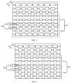
- FIG. 1 is a top view of a first solar cell provided according to an embodiment of the present application.
- the solar cell includes multiple finger electrodes 101 arranged at intervals along a first direction X.
- the finger electrodes 101 are arranged on a surface of the substrate 100 and each of the finger electrodes 101 extends along a second direction Y.
- each finger electrode 101 including multiple body portions 111 and multiple widened portions 121 arranged alternatingly along the second direction Y.
- the widened portion 121 is a portion connected to the welding strip.
- the embodiments of the present application provides a solar cell that additionally widens the widened portion 121 close to the edges of the substrate 100, such that the orthographic projections of the widened portions 121 close to the edges of the substrate 100 on the substrate 100 is larger than the orthographic projections of the widened portions 121 away from the edge of the substrate 100 on the substrate 100, thereby improving the reliability of the connection between the finger electrodes 101 and the welding strips.
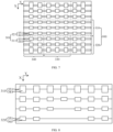
- FIG. 2 is a top view of a second solar cell provided according to an embodiment of the present application.
- the substrate 200 includes: a central region 210 and two peripheral regions 220 arranged on two opposite sides of the central region 210 along the first direction X, respectively.
- the finger electrodes 201 arranged in the peripheral region 220 is defined as the first finger electrode 211
- the finger electrodes 201 arranged in the central region 210 is defined as the second finger electrode 221.
- Each of the first finger electrodes 211 includes multiple first body portions 231 and multiple first widened portions 241 arranged alternatingly along the second direction Y.
- Each of the multiple second finger electrodes 221 includes multiple second body portions 251 and multiple second widened portions 261 arranged alternatingly along the second direction Y.
- the first widened portion 241 and the second widened portion 261 are arranged in columns along the first direction X, and the first widened portion 241 has a larger orthographic projection on the substrate 200 than the second widened portions 261 on the substrate 200.
- the first widened portion 241 has a larger orthographic projection on the substrate 200 than the first body portion 231 on the substrate 200, and the second widened portion 261 has a larger orthographic projection on the substrate 200 than the second body portion 251.
- the first widened portions 241 have the orthographic projections with the same area, the size of different first widened portions 241 along the first direction X is the same, the size of different first widened portions 241 along the second direction Y is also the same.
- the reliability of the connection between the first finger electrode 211 arranged in the peripheral region 220 and the welding strip can be improved, thereby improving the reliability of the photovoltaic module formed subsequent.
- FIG. 3 is a top view of a third solar cell provided according to an embodiment of the present application.
- the solar cell provided according to the embodiments of the present application includes a substrate 300, which includes a central region 310 and peripheral regions 320 arranged on two opposite sides of the central region 310 along the first direction X, respectively.
- the solar cell further includes multiple finger electrodes 301 arranged on a surface of the substrate 300 and extend along a second direction Y, and the multiple finger electrodes 301 include multiple first finger electrodes 311 and multiple second finger electrodes 321, each of the two peripheral regions 320 has at least one first finger electrodes 311, and the multiple second finger electrodes 321 are arranged in the central region 310.
- a respective first finger electrode 311 of the multiple first finger electrodes 311 includes first body portions 331 and first widened portions 341 arranged alternatingly along the second direction Y
- a respective second finger electrode 321 of the multiple second finger electrodes 321 includes second body portions 351 and second widened portions 361 arranged alternatingly along the second direction Y.
- the first widened portions 341 are arranged and aligned to the second widened portions 361 along the first direction X.
- Each of the first widened portions 341 has a larger orthographic projection on the substrate 300 than each of the second widened portion 361, each of the first widened portions 341 has a larger orthographic projection on the substrate 300 than each of the first body portions 331, each of the second widened portions 361 has a larger orthographic projection on the substrate than each of the second body portions 351, and along the first direction, a respective first widened portion 341 of a respective first finger electrode 311 in two first finger electrodes 311 farthest from the central region 310 on the substrate 300 has a larger orthographic projection than a respective first widened portion 341 of each of two first finger electrode 311 closet to the central region 310.
- FIG. 3 there are two peripheral regions 320 arranged on two sides of the central region 310 along the first direction X, respectively. Therefore, there are two first finger electrodes 311 closet to the central region 310 along the first direction X, and the two first finger electrodes 311 closet to the central region 310 are arranged in the two peripheral region 320, respectively. Similarly, there are two first finger electrodes farthest from the central region 310 along the first direction X, and the two first finger electrodes 311 farthest from the central region 310 are arranged in the two peripheral region 320, respectively.
- the first finger electrode 311 includes first body portions 341 and first widened portions 331 arranged alternatingly along the second direction Y.
- the first widened portion 341 refers to a part where the solar cell is connected to the welding strip corresponding to a cell string when connecting the solar cell to form the cell string.
- the probability of failure between the first finger electrode 311 arranged in the peripheral region 320 and the welding strip is greater than that of failure between the second finger electrode 321 arranged in the central region 310 and the welding strip. Therefore, it is also set that the orthographic projections of the first widened portion 341 on the substrate 300 is larger than the orthographic projections of the second widened portion 361, which can further improve the reliability of the connection between the first finger electrode 311 arranged in the peripheral region 320 and the welding strip. In addition, the probability of failure in the connection between the first finger electrode 311 farthest from the central region 310 and the welding strip is greater than that of the connection between the first finger electrode 311 closest to the central region 310 and the welding strip.
- the orthographic projections of the first widened portion 341 of the first finger electrode 311 farthest from the central region 310 on the substrate 300 is larger than the orthographic projections of the first widened portion 341 of the first finger electrode 311 closest to the central region 310 on the substrate 300, which can further improve the reliability of the connection between the solar cell and the welding strip.
- the substrate 300 is a substrate 300 that has already formed a partial structure of the solar cell.
- the tunnel oxide passivated contact (TOPcon) solar cell is taken as an example, a tunneling layer, a doped conductive layer, a passivation layer, and other film layers are already formed on the substrate 300.
- the substrate 300 may also be other types of solar cell structures, for example, a heterojunction cell or a busbar-free cell, etc.
- the central region 310 and the two peripheral regions 320 are divisions of the substrate 300.
- the central region 310 and two peripheral regions 320 are three parts of the substrate 300 along the first direction X, with the middle part referred to as the central region 310 and other two parts referred to as the peripheral regions 320, and a ratio of the volume of any peripheral region 320 of the substrate 300 to the volume of the substrate 300 is less than or equal to 1/3. In other words, a ratio of the area of any peripheral region 320 of the substrate 300 on the top surface of the substrate 300 to the top surface of the substrate 300 is less than or equal to 1/3.
- the size of the first widened portion 341 and the second widened portion 361 along the second direction Y can be greater than the size of the welding strip along the second direction Y. On the one hand, it can facilitate the alignment of the welding strip with the first widened portions 341 and the second widened portions 361. On the other hand, there may be lamination and other processes during the formation of the photovoltaic module, which may cause deformation of the welding strip. By setting the size of the first widened portion 341 and the second widened portion 361 along the second direction Y to be greater than the size of the welding strip, a region to be in contact with the welding strip can be reserved.
- the first widened portions 341 and the first body portions 331 can be integrally formed, in other words, the first widened portions 341 and the first body portions 331 are formed in the same process step by using the same slurry. In some embodiments, the first widened portions 341 and the first body portions 331 are two interconnected structures. In other words, the first widened portions 341 and the first body portions 331 are formed in different process steps by using the same or different slurries.
- FIG. 3 is a top view of a third solar cell provided according to an embodiment of the present application.
- FIG. 4 is a top view of a fourth solar cell provided according to an embodiment of the present application.
- FIG. 5 is a top view of a fifth solar cell provided according to an embodiment of the present application.
- FIG. 6 is a top view of a sixth solar cell provided according to an embodiment of the present application.
- At least one of the first widened portions 341 in a same column of the columns gradually increases in orthographic projection area on the substrate 300 along the first direction X or a direction opposite to the first direction X.
- the number of finger electrodes 301 included in FIG. 3 is 9.
- the number of second finger electrodes 321 in the central region 310 is 3
- the number of first finger electrodes 311 on one side of the second finger electrode 321 is 3.
- the three first finger electrodes 311 in one of the peripheral regions 320 are named as a first of first finger electrode, a second of first finger electrode, and a third of first finger electrode, respectively from the central region 310 to the peripheral region 320.
- At least one of the first widened portions 341 in a same column of the columns gradually increases in orthographic projection area on the substrate 300, which can refer to: the first widened portion 341 of the first of first finger electrode has a smaller orthographic projection area on the substrate 300 than the first widened portion 341 of the second of first finger electrode, and the first widened portion 341 of the second of first finger electrode has a smaller orthographic projection area on the substrate 300 than the first widened portion 341 of the third of first finger electrode.
- the first widened portion 341 of the first of first finger electrode has a smaller orthographic projection area on the substrate 300 than the first widened portion 341 of the second of first finger electrode, and the first widened portion 341 of the second of first finger electrode has the same orthographic projection area on the substrate 300 than the first widened portion 341 of the third of first finger electrode. It can also refer to the first widened portion 341 of the first of first finger electrode has the same orthographic projection area on the substrate 300 than the first widened portion 341 of the second of first finger electrode, and the first widened portion 341 of the second of first finger electrode has a smaller orthographic projection area on the substrate 300 than the first widened portion 341 of the third of first finger electrode.
- the number of the first finger electrode 311 on one side of the central region 310 being 3 is taken as an example in the above explanation, and the number of the first finger electrode 311 in the peripheral region 320 may also be other quantities. That is to say, there are more cases for the expression of at least one of the first widened portions 341 in a same column of the columns gradually increasing in orthographic projection area on the substrate 300.
- the orthographic projection area of the first widened portion 341 of the first finger electrode 311 on the substrate 300 above refers to: in response to the number of first widened portions 341 being one, it refers to the area of this first widened portion 341, in response to the number of first widened portions 341 being multiple, the orthographic projection area of the first widened portion 341 of the first finger electrode 311 on the substrate 300 can refer to the orthographic projection area of any first widened portion 341 of the first finger electrode 311 on the substrate 300, or it can refer to the average orthographic projection area of the multiple first widened portions 341 of the first finger electrode 311 on the substrate 300.
- At least one of the first widened portions 341 in a same column of the columns may not gradually increases in orthographic projection area on the substrate 300 along the first direction X or a direction opposite to the first direction X, and the orthographic projection area may change irregularly.
- the number of the first finger electrodes 311 on one side of the central region 310 being 3 is taken as an example, the first widened portion 341 of the first of first finger electrode 311 on the substrate 300 has a larger orthographic projection area than the first widened portion 341 of the second of first finger electrode 311, and the first widened portion 341 of the third of first finger electrode 311 on the substrate 300 has a larger orthographic projection area than the first widened portion 341 of the first of first finger electrode 311.
- some of the first widened portions 341 in the same column of the columns have the same orthographic projection area on the substrate 300, and the morphological dimensions of these first widened portion 341 are the same.
- different first widened portions 341 in a same column of the columns gradually increases in size along the first direction X
- different first widened portions 341 in the same column of the columns gradually increases in size along the second direction Y.
- the two factors that affect the area parameter are the size and size of the first widened portion 341. Therefore, by changing the size and/or size of different first widened portions 341 in the same column of the columns, the orthographic projection area of the first widened portions 341 in the same column of the columns on the substrate 300 can be adjusted.
- the size of different first widened portions 341 in the same column of the columns along the first direction X gradually increases.
- the size of different first widened portions 341 in the same column of the columns along the second direction Y can gradually increase, remain unchanged, or gradually decrease.
- FIG. 3 shows that the size of different first widened portions 341 in the same column of the columns gradually increases along the first direction X, while the size of different first widened portions 341 in the same column of the columns remains equal along the second direction Y.
- FIG. 4 shows that the size of different first widened portions 341 along the first direction X in the same column of the columns gradually increases, while the size of different first widened portions 341 along the second direction Y in the same column of the columns gradually increases.
- the size gradually increases that is, the farther away from the central region 310, the larger the size of the first widened portion 341, which can improve the reliability of the connection between the first finger electrode 311 at the edges and the welding strip.
- the size remains unchanged, that is, the size of different first widened portions 341 in the same column of the columns is equal, which can simplify the process steps of forming the first finger electrode 311.
- the size gradually decreases that is, the farther away from the central region 310, the smaller the size of the first widened portion 341, which can balance the amount of slurry used.
- the size difference between two adjacent first widened portions 341 in the same column of the columns along the first direction X is less than or equal to 0.2mm, such as 0.05mm, 0.1mm, or 0.15mm.
- the size difference between the adjacent first widened portions 341 can be reduced. On the one hand, it can improve the aesthetics of the solar cell, and on the other hand, it can avoid anomalies caused by excessive size differences between adjacent first widened portions 341.
- the maximum size of the first widened portion 341 farthest from the central region 310 along the second direction Y is 0.6mm to 0.8mm, such as 0.65mm, 0.68mm, or 0.75mm, etc. It can be understood that in response to the maximum size of the first widened portion 341 farthest from the central region 310 along the second direction Y being less than 0.6mm, the reliability of the connection between the first finger electrode 311 and the welding strip is improved.
- the shading area of the first widened portion 341 may be too large, which may lead to a decrease in the photovoltaic conversion efficiency of the solar cell.
- the size of different first widened portions 341 in the same column of the columns gradually increases along the second direction Y, and the size of different first widened portions 341 in the same column of the columns along the first direction X may gradually increase, remain unchanged, or gradually decrease.
- FIG. 4 shows that the size of different first widened portions 341 in the same column of the columns gradually increases along the second direction Y, and the size of different first widened portions 341 in the same column of the columns gradually increases along the first direction X.
- FIG. 5 shows that the size of different first widened portions 341 in the same column of the columns gradually increases along the second direction Y, and the size of different first widened portions 341 in the same column of the columns remains unchanged along the first direction X.
- the size difference between two adjacent first widened portions 341 in the same column of the columns along the second direction Y is less than or equal to 0.3mm, such as 0.1mm, 0.2mm, or 0.25mm, etc.
- the size difference between the two adjacent first widened portions 341 in the same column of the columns along the second direction Y can be reduced. On the one hand, it can improve the aesthetics of the solar cell, and on the other hand, it can avoid anomalies caused by excessive size differences between adjacent first widened portions 341.
- the maximum size of the first widened portion 341 farthest from the central region 310 along the second direction Y is 1mm to 1.6mm, such as 1.1mm, 1.2mm, or 1.4mm, etc. It can be understood that in response to the maximum size of the first widened portion 341 farthest from the central region 310 along the second direction Y being less than 1mm, the reliability of the connection between the first finger electrode 311 and the welding strip is improved.
- the shading area of the first widened portion 341 may be too large, which may lead to a decrease in the photovoltaic conversion efficiency of the solar cell.
- the size gradually increases that is, the farther away from the central region 310, the wider the first widened portion 341 becomes, which can improve the reliability of aligning the first finger electrode 311 at the edges with the welding strip.
- the size remains unchanged, that is, the size of different first widened portions 341 in the same column of the columns is equal, which can simplify the process steps of forming the first finger electrode 311.
- the size gradually decreases, that is, the farther away from the central region 310, the smaller the size of the first widened portion 341, which can balance the amount of slurry used.
- the size of the first widened portion 341 is the dimension along the first direction X, and the size is the dimension along the second direction Y.
- the size of the first widened portion 341 can be considered as the projection dimension of the two points with the longest distance along the first direction X of the first widened portion 341
- the size can be considered as the projection dimension of the two points with the longest distance along the second direction Y of the first widened portion 341.
- the two peripheral regions 320 arranged on opposite sides of the central region 310 are symmetrically distributed.
- the number of first finger electrodes 311 in each of the two peripheral regions 320 is 3.
- the first of first finger electrodes, the second of first finger electrodes, and the third of first finger electrodes in the two peripheral regions are the same. That is to say, the morphology and size of the first widened portion 341 and the first body portion 331 of the symmetrically distributed first finger electrode 311 are the same, which can reduce the process difficulty of the solar cell.
- the peripheral regions 320 arranged on two opposite sides of the central region 310 are asymmetrically distributed.
- the size of different first widened portions 341 in the same column of the columns of the peripheral region 320 arranged on one side of the central region 310 gradually increases along the first direction X
- the size of different first widened portions 341 in the same column of the columns of the peripheral region 320 arranged on the other side of the central region 310 gradually increases along the second direction Y.
- the size of different first widened portions 341 in the same column of the columns along the second direction Y is equal, and/or the size of different second widened portions 361 in the same column of the columns along the second direction Y is equal.
- the size of different first widened portions 341 in the same column of the columns along the second direction Y is equal, and the size of different second widened portions 361 in the same column of the columns along the second direction Y may be equal, gradually decreases or gradually increases.
- FIG. 3 only show that the size of different first widened portions 341 in the same column of the columns is equal along the second direction Y, and the size of different second widened portions 361 in the same column of the columns is equal along the second direction Y.
- the size of different second widened portions 361 in the same column of the columns along the second direction Y is equal, and the size of different first widened portions 341 in the same column of the columns along the second direction Y may be equal, gradually decreases or gradually increases.
- the different first widened portions 341 in the same column of the columns refer to the different first widened portions 341 connected to the same welding strip in the future
- the different second widened portions 361 in the same column of the columns refer to the different second widened portions 361 connected to the same welding strip in the future.
- the size of the first widened portion 341 in the same column of the columns is equal to the size of the second widened portion 361.
- the size of the first widened portion 341 and the second widened portion 361 connected to the same welding strip are both equal, which can also reduce the process difficulty of the solar cell.
- FIG. 7 is a top view of a seventh solar cell provided according to an embodiment of the present application.
- Each of the two peripheral regions 320 includes a first sub region 330 and a second sub region 340 arranged on opposite sides of the first sub region 330 along the second direction Y.
- the average surface area of the first widened portion 341 of the first sub region 330 is smaller than the average area of the first widened portion 341 of the second sub region 340. It can be understood that for the solar cell, the second sub region 340 is closer to the edge of the solar cell compared to the first sub region 330.
- the reliability of the connection between the edge part of the solar cell and the welding strip can be further increased, thereby improving the reliability of the solar cell.
- the average area of the first widened portion 341 of the first sub region 330 is smaller than that of the first widened portion 341 of the second sub region 340. That is, each of the first widened portions 341 of the first sub region 330 has a smaller orthographic projection on the substrate than each of the first widened portion 341 of the second sub region 340, or it can be that each of the first widened portions 341 of the first sub region 330 has a smaller orthographic projection on the substrate than each of the first widened portions 341 of the second sub region 340.
- the first body portion 331 and the first widened portion 341 can be freely arranged.
- the size of the first body portion 331 along the second direction Y of different first finger electrodes 311 can be different.
- FIG. 8 which is an enlarged view of the dashed box in FIG. 3 . It can be seen that there is a longest first body portion 331 in the first finger electrode 311 closest to the center area, in other words, the number of first widened portions 341 on the first finger electrode 311 closest to the center area is the smallest.
- the size of at least a portion of the first widened portion 341 arranged on the same first finger electrode 311 in the second sub region 340 gradually increases. It can be understood that the greater the size, the stronger the reliability of connecting with the welding strip, and the more it is arranged at the edge of the solar cell, the stronger the reliability is required. Therefore, the size of at least a portion of the first widened portion 341 on the same first finger electrode 311 gradually increases, which can increase the reliability of connection with the welding strip at the edge of the solar cell.
- the gradual increase in size of at least one of the first widened portions 341 mentioned above can refer to the increase in size of all the first widened portions 341 arranged in the second sub region 340.
- the number of first widened portions 341 arranged in the second sub region 340 in a first finger electrode 311 is 3.
- the 3 first widened portions 341 are sequentially named as a first of first widened portion, a second of first widened portion, and a third of first widened portion along the direction from the first sub region 330 towards the second sub region 340.
- the size of the first of first widened portion is smaller than that of the second first widened portion, and the size of the second of first widened portion is smaller than the size of the third of first widened portion.
- At least one of the first widened portions 341 gradually increases in size, which can also refer to only a part of the first widened portions 341 gradually increases in size.
- the number of first widened portions 341 arranged in the second sub region 340 of a first finger electrode 311 being 3 is taken as an example, where the size of the first of first widened portion can be smaller than the size of the second of first widened portion, the size of the second of first widened portion can be equal to the size of the third of first widened portion, or the size of the first of first widened portion can be equal to the size of the second of first widened portion, and the size of the second of first widened portion can be smaller than the size of the third of first widened portion.
- first widened portions 341 arranged in the second sub region 340 of a first finger electrode 311 is 3 as an example.
- the number of first widened portions 341 arranged in the second sub region 340 of a first finger electrode 311 may also be other quantities. That is to say, the size of at least one of the first widened portions 341 on the same first finger electrode 311 arranged in the second sub region 340 gradually increases, and there can be more arrangement options.
- the substrate 300 has a first axis parallel to the first direction X, and the substrate 300 is symmetrical along the first axis.
- the size of a part away from the first axis is greater than the size of the part close to the first axis.
- the shape of the first widened portion 341 is a trapezoid rotated by 90 degrees, and for the first widened portion 341 arranged on the first axis, the shape of the first widened portion 341 is in a tie shape.
- the farther away from the first axis the more it belongs to the edge part of the solar cell. Therefore, by setting the size of the part away from the first axis to be greater than the size of the part close to the first axis, the reliability of the solar cell can be further improved.
- the first widened portion 341 at different positions in the solar cell is asymmetric.
- the peripheral regions 320 arranged on two opposite sides of the central region 310 are taken as an example, the first widened portion 341 on the first finger electrode 311 closest to the central region in one peripheral region 320 may have a different morphology or size from the first widened portion 341 on the first finger electrode 311 closest to the central region 310 in another peripheral region 320.
- the peripheral region 320 includes the first sub region 330 and two second sub regions 340, where the morphology or size of the first widened portion 341 in a column closest to the first sub region 330 in one second sub region 340 and the first widened portion 341 in a column closest to the first sub region 330 in another second sub region 340 are different.
- the size of the first body portion 331 is the same as that of the second body portion 351. It can be understood that the first body portion 331 and the second body portion 351 are also arranged in columns along the first direction.
- the size of the first body portion 331 and the size of the second body portion 351 are the same, which means that in the same column of the columns, the size of the first body portion 331 and the second body portion 351 are the same.
- the size of all first body portions 331 on the same first finger electrode 311 is the same.
- the size of all second body portions 351 on the same second finger electrode 321 is the same.
- the size of all first body portions 331 and all second body portions 351 are the same.
- FIG. 10 is a schematic diagram of the top view of a tenth solar cell provided according to an embodiment of the present application.
- at least one the first body portions 331 in the same column of the columns gradually increases in size along the first direction or the direction opposite to the first direction X.
- the welding strips not only in contact with and connect to the first widened portion 341, but also in contact with and connect to a part of the first body portion 331. Therefore, at least one the first body portions 331 in the same column of the columns gradually increases in size, which can increase the reliability of the connection between the welding strips and the first finger electrodes 311.
- the gradual increase in size of at least one of the first body portions 331 can refer to the increase in size of all the first body portions 331 along the first direction or the direction opposite to the first direction X.
- the number of first body portions 331 is three, where the three first body portions 331 are named as a first of first body portion, a second of first body portion, and a third of first body portion along the second direction Y or the direction opposite to the second direction Y.
- the size of the first of first body portion is smaller than that of the second of first body portion, and the size of the second of first body portion is smaller than that of the third of first body portion.
- At least one of the first body portions 331 gradually increases in size, which can also refer to only a part of the first body portions 331 gradually increases in size.
- the number of first body portions 331 is three.
- the size of the first of first body portion is smaller than the size of the second of first body portion
- the size of the second of first body portion is equal to the size of the third of first body portion
- the size of the first of first body portion is equal to the size of the second of first body portion
- the size of the second of first body portion is smaller than the size of the third of first body portion.
- the first widened portions 341 and/or the second widened portions 361 have a rectangular shaped, an elliptical shaped, or a wave shaped orthographic projections on the substrate 300.
- regular shapes can facilitate the production process of the first widened portions 341 and the second widened portions 361, thereby reducing the difficulty of forming the solar cell.
- the first widened portions 341 with the wave shaped orthographic projections can increase the contact area with the welding strip while reducing the amount of material required to form the finger electrodes 301.
- the number of first finger electrodes 311 on one side of the second finger electrode 321 is 2 to 10, such as 3, 5, 7, or 9. It can be understood that the more the number of first finger electrodes 311, the larger the area of the peripheral region 320, the fewer the number of first finger electrodes 311, and the smaller the area of the peripheral region 320.
- the number of first finger electrodes 311 on one side of the second finger electrode 321 to 2 to 10 that is, setting the number of finger electrodes 301 with the first widened portion 341 to 2 to 10.
- the maximum size of the first widened portion 341 along the first direction X is 0.05mm to 0.8mm, such as 0.1mm, 0.3mm, or 0.5mm, etc. It can be understood that the larger the maximum size of the first widened portion 341, the higher the reliability of the connection with the welding strip. However, the larger the maximum size, the higher the possibility of interconnection between adjacent finger electrodes 301. Therefore, by setting the maximum size of the first widened portion 341 along the first direction to 0.05mm to 0.8mm, it is possible to increase the reliability of the connection with the welding strip while creating a certain gap between adjacent finger electrodes 301.
- the maximum size of the first widened portion 341 along the first direction X can refer to the maximum projection size of any two points on the first widened portion 341 along the first direction X.
- the maximum size of the first widened portion 341 along the second direction Y is 0.5mm to 1.6mm, such as 0.7mm, 0.9mm, 1.1mm, or 1.3mm.
- the maximum size of the first widened portion 341 along the second direction Y can refer to the maximum projection size of any two points on the first widened portion 341 along the second direction Y.
- the first finger electrode 311 includes first body portions 341 and first widened portions 331 arranged alternatingly along the second direction Y.
- the first widened portion 341 refers to a part where the solar cell is connected to the welding strip corresponding to a cell string when connecting the solar cell to form the cell string.
- the probability of failure between the first finger electrode 311 arranged in the peripheral region 320 and the welding strip is greater than that of failure between the second finger electrode 321 arranged in the central region 310 and the welding strip. Therefore, it is also set that the orthographic projections of the first widened portion 341 on the substrate 300 is larger than the orthographic projections of the second widened portion 361, which can further improve the reliability of the connection between the first finger electrode 311 arranged in the peripheral region 320 and the welding strip. In addition, the probability of failure in the connection between the first finger electrode 311 farthest from the central region 310 and the welding strip is greater than that of the connection between the first finger electrode 311 closest to the central region 310 and the welding strip.
- the orthographic projections of the first widened portion 341 of the first finger electrode 311 farthest from the central region 310 on the substrate 300 is larger than the orthographic projections of the first widened portion 341 of the first finger electrode 311 closest to the central region 310 on the substrate 300, which can further improve the reliability of the connection between the solar cell and the welding strip.
- a photovoltaic module is further provided according to another embodiment of the present application, and the photovoltaic module includes the solar cell according to above embodiments.
- the following will explain the photovoltaic module provided according to another embodiment of the present application in conjunction with the accompanying drawings. It is necessary to note that the same or corresponding parts of the above embodiments can be referred to in the corresponding explanation of the above embodiments, which will not be elaborated below.
- FIG. 11 is a three-dimensional view of a first photovoltaic module provided according to an embodiment of the present application.
- FIG. 12 is a top view of the first photovoltaic module provided according to an embodiment of the present application.
- FIG. 13 is a top view of a second photovoltaic module provided according to an embodiment of the present application.
- FIG. 14 is a top view of a third photovoltaic module provided according to an embodiment of the present application.
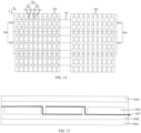
- FIG. 15 is a cross-sectional view of the first photovoltaic module provided according to another embodiment of the present application along dash line M1-M2.
- a photovoltaic module is further provided according to another embodiment of the present application, and the photovoltaic module includes: a cell string including edge cells 505 arranged close to edges of the photovoltaic module and a central cell 506, each of the edge cells 505 includes a substrate 500 having a central region 510 and two peripheral regions 520 formed on two opposite sides of the central region 510 along a first direction X, respectively, and multiple finger electrodes 501 are arranged at intervals along the first direction X.
- the multiple finger electrodes 501 are arranged on a surface of the substrate 500 and extend along a second direction Y, and the multiple finger electrodes 501 include multiple first finger electrodes 511 arranged in the two peripheral regions 520 and multiple second finger electrodes 521 arranged in the central region 510.
- a respective first finger electrode 511 of the multiple first finger electrodes 511 includes first body portions 531 and first widened portions 541 arranged alternatingly along the second direction Y
- a respective second finger electrode 521 of the multiple second finger electrodes 521 includes second body portions 551 and second widened portions 561 arranged alternatingly along the second direction Y
- the first widened portions 541 are arranged and aligned to the second widened portions 561 along the first direction X.
- the first widened portions 541 have larger orthographic projections on the substrate 500 than the second widened portions 561, the first widened portions 541 have larger orthographic projections on the substrate 500 than the first body portions 531, the second widened portions 561 have larger orthographic projections on the substrate 500 than the second body portions 551, and a respective first widened portion 541 of a respective first finger electrode 511 in two first finger electrodes 511 farthest from the central region 510 has a larger orthographic projection on the substrate 500 than a respective first widened portion 541 of a first finger electrode 511arranged in a middle of the central region 510.
- the photovoltaic module further includes welding strips 507 arranged at intervals along the second direction Y and extending along the first direction X, a respective welding strip 507 in the multiple welding strips 507 is in contact and connected to the first widened portions 541 and the second widened portions 561 in a same respective column to connect two adjacent cells.
- the photovoltaic modules provided according to the embodiments of the present application further includes at least one encapsulation adhesive film 508 configured to cover the at least one cell string.
- the photovoltaic module provided according to the embodiments of the present application further includes at least one cover plate 509 configured to cover the at least one encapsulation adhesive film 508.
- the photovoltaic module provided according to the embodiments of the present application includes at least one cell string including edge cells 505 and a central cell 506.
- the reliability of the edge cells 505 is relatively low. Therefore, by setting the edge cells 505 to include first body portions 531 and first widened portions 541, and the first widened portions 541 have larger orthographic projections on the substrate 500 than the first body portions 531, the reliability of the connection between the first finger electrode 511 and the welding strip 507 can be increased.
- the probability of failure between the first finger electrode 511 arranged in the peripheral region 520 and the welding strip is greater than that of failure between the second finger electrode 521 arranged in the central region 510 and the welding strip.
- the orthographic projections of the first widened portion 541 on the substrate 500 is larger than the orthographic projections of the second widened portion 561, which can further improve the reliability of the connection between the first finger electrode 511 arranged in the peripheral region 520 and the welding strip.
- the probability of failure in the connection between the first finger electrode 511 farthest from the central region 510 and the welding strip is greater than that of the connection between the first finger electrode 511 closest to the central region 510 and the welding strip.
- the orthographic projections of the first widened portion 541 of the first finger electrode 511 farthest from the central region 510 on the substrate 500 is larger than the orthographic projections of the first widened portion 541 of the first finger electrode 511 closest to the central region 510 on the substrate 500, which can further improve the reliability of the connection between the edge cells 505 and the welding strips 507, and thereby improving the reliability of the photovoltaic module.
- edge cells 505 may be the two or four outermost edge cells in a cell string.
- the outermost edge cells here can refer to the several outermost edge cells along the second direction Y of the cell string.
- the central cell 506 is a cell arranged between edge cells 505, and the structure of the central cell 506 is the same as that of the edge cells 505. Reference may be made to the corresponding structures shown in FIG. 1 and FIG. 2 and related explanations, which will not be repeated here.
- each of the at least one encapsulation adhesive film 508 includes a first encapsulation layer (not shown) and a second encapsulation layer (not shown), where the first encapsulation layer is configured to cover one of a front surface or a rear surface of the solar cell, and the second encapsulation layer is configured to cover the other of the front surface or the rear surface of the solar cell.
- At least one of the first encapsulation layer or the second encapsulation layer is an organic encapsulation adhesive film, such as a polyvinyl butyral (PVB) film, an ethylene vinyl acetate copolymer (EVA) film, a polyolefin thermoplastic elastomer (POE) film, or a polyethylene glycol terephthalate (PET) film.
- PVB polyvinyl butyral
- EVA ethylene vinyl acetate copolymer
- POE polyolefin thermoplastic elastomer
- PET polyethylene glycol terephthalate
- first encapsulation layer and the second encapsulation layer have a boundary before the lamination process. After the lamination process, the concept of the first encapsulation layer and the second encapsulation layer will no longer exist in the formed photovoltaic module, that is, the first encapsulation layer and the second encapsulation layer have formed a complete encapsulation adhesive film 508.
- each of the at least one cover plate 509 may be a glass cover plate, a plastic cover plate, or other cover plates with transparent functions.
- a surface of each of the at least one cover plate 509 facing toward the at least one encapsulation adhesive film 508 is a surface with protrusions and recesses, thereby increasing the utilization of incident light.
- the at least one cover plate 509 includes a first cover plate and a second cover plate, the first cover plate is arranged opposite to the first encapsulation layer and the second cover plate is arranged opposite to the second encapsulation layer.
- the first widened portions 541 of each respective first finger electrode 511 of a respective edge cell 505 closest to the central cell 506 have smaller orthographic projections on the substrate 500 than the first widened portions 541 of the first finger electrodes 511 of a respective edge cell 505 farthest away from the central cell 506.
- the edge cells 505 there is a side close to the central cell 506 and a side away from the central cell.
- the first finger electrode 511 away from the central cell 506 has a higher probability of failure in connection with the welding strip. Therefore, by setting the first widened portions 541 of the first finger electrode 511 away from the central cell 506 to have larger orthographic projections on the substrate 500, the reliability of the connection between the first finger electrode 511 away from the central cell 506 and the welding strip 507 can be increased.
- At least one of the first widened portions 541 of each respective first finger electrode 511 of a respective edge cell 505 closest to the central cell 506 has a larger orthographic projection on the substrate 500 than some of the first widened portions 541 in a same column of the columns along the first direction X of each respective first finger electrodes 511 of two edge cells 505 closest to the central cell 506.
- edge cells 505 close to the central cell 506 have relatively higher reliability in connecting to the welding strip 507.
- the orthographic projection area of at least one the first widened portion 541 of the edge cell 505 farthest from the central cell 506 on the substrate 500 is defined as a first area
- the orthographic projection area of at least one the first widened portions 541 of the edge cell 505 closest to the central cell 506 in the same column of the columns along the first direction X on the substrate 500 is defined as a second area.
- the first widened portions 541 and the second widened portions 561 are arranged in a column along the first direction X, and for the cell string, the solar cells are also arranged along the first direction X. Therefore, there is not only the first widened portions 541 and the second widened portions 561 of one solar cell arranged in a column along the first direction X.
- each respective first finger electrode 511 of a respective edge cell 505 closest to the central cell 506 has a larger orthographic projection on the substrate 500 than some of the first widened portions 541 in a same column of the columns along the first direction X of each respective first finger electrodes 511 of two edge cells 505 closest to the central cell 506, the reliability of the connection between the edge cells 505 and the welding strips 507 can be increased.
- At least one of the first widened portions 541 may refer to: all first widened portions 541 in the edge cell 505 farthest from the central cell 506 have larger orthographic projections on the substrate 500 than all first widened portions 541 in the edge cell 505 closest to the central cell 506. At least one of the first widened portions 541 may also refer to: the first widened portions 541 on the first finger electrode 511 farthest from the central cell 506 in the edge cell 505 farthest to the central cell 506 have larger orthographic projections on the substrate 500 than the first widened portions 541 on the first finger electrode 511 farthest from the central cell 506 in the edge cell 505 closest to the central cell 506.
- At least one of the first widened portions 541 may also refer to: any first widened portion 541 in the edge cell 505 farthest from the central cell 506 has a larger orthographic projection on the substrate 500 than any first widened portion 541 in the edge cell 505 closest to the central cell 506.
- any of the first widened portions 541 of each respective first finger electrodes 511 of a respective edge cell 505 farthest from the central cell 506 has a larger orthographic projection on the substrate 500 than any of the first widened portions 541 in a same column of the columns along the first direction X of each respective first finger electrodes 511 of a respective edge cell 505 closest to the central cell 506.
- all first widened portions 541 of the edge cell 505 farthest from the central cell 506 have larger orthographic projections on the substrate 500 than all first widened portions 541 of the edge cell 505 closest to the central cell 506, thereby further improving the reliability of connection in the photovoltaic module.
- the photovoltaic module includes two first regions 502 and a second region 503, and the two first regions 502 are arranged on opposite sides of the second region 503 along the second direction Y, respectively. It can be understood that the two first regions 502 belong to the peripheral part of the photovoltaic module compared to the second region 503.
- the first widened portions 541 of a respective first region 502 farthest from the second region 503 have larger orthographic projections on the substrate 500 than the first widened portions 541 of the respective first region 502 closest to the second region 503 and in the same row along the second direction Y.
- the orthographic projection area of the first widened portions 541 on the substrate 500 in the same first finger electrode 511 is different.
- the first widened portion 541 closest to the second region 503 on the substrate 500 has a smaller orthographic projection on the substrate 500 than the first widened portion 541 farthest from the first region 502.
- the reliability of the connection between the welding strip 507 and the finger electrode 501 in the photovoltaic module can be further improved.
- the second widened portion 561 in the first region 502 farthest from the second region 503 has a larger orthographic projection on the substrate 500 than the second widened portion 561 in the same first region 502 closest to the second region 503 and in the same row along the second direction Y.
- the orthographic projection area of the second widened portions 561 in the same second finger electrode 521 on the substrate 500 is different.
- the second widened portion 561 closest to the second region 503 has a smaller orthographic projection on the substrate 500 than the second widened portion 561 farthest from the first region 502.
- At least one the first widened portions 541 on the same first finger electrode 511 in the first region 502 gradually increases in the orthographic projection area on the substrate 500
- at least one of the second widened portions 561 on the same second finger electrode 521 in the first region 502 gradually increases in the orthographic projection area on the substrate 500.
- variation in the orthographic projection area can refer to the variation in the orthographic projection area of the first widened portion of the edge region in the solar cell mentioned above, which will not be repeated here.
- the photovoltaic module includes multiple cell strings.
- the multiple cell strings are arranged along the second direction Y in FIG. 11 .
- there are edge cell strings and a central cell string and the edge cell strings naturally has a side close to the central cell string and a side away from the central cell string.
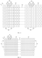
- FIG. 14 which is a top view of a third photovoltaic module provided according to an embodiment of the present application.
- FIG. 14 shows an edge cell string, and the edge cell string includes a first region 502 on a side away from the central cell string, a second region 503, and a first region 502 on the other side close to the central cell string.
- the average orthographic projection area of the first widened portions 541 of the first region 502 away from the central cell string on the substrate 500 is larger than the average orthographic projection area of the first widened portions 541 of the first region 502 close to the central cell string on the substrate 500.
- the first region 502 away from the central cell string belongs to a part closer to the edges of the photovoltaic module. Therefore, the reliability of the photovoltaic module can be further improved by setting the average orthographic projection area of the first widened portions 541 of the first region 502 away from the central cell string on the substrate 500 to be larger than the average orthographic projection area of the first widened portions 541 of the first region 502 close to the central cell string on the substrate 500.
- the first widened portions 541 in the first region 502 on two opposite sides of the second region 503 is at least partially different in morphology.
- the average orthographic projection area of the second widened portions 561 of the first region 502 on the substrate 500 away from the side of the central cell string is larger than the average orthographic projection area of the second widened portions 561 of the first region 502, which can further improve the reliability of the photovoltaic module.
- the average orthographic projection area of the first widened portions 541 in the second region 503 on the substrate 500 is equal to the average orthographic projection area of the first widened portions 541 in the first region 502 close to the side of the central cell string.
- the average orthographic projection area of the second widened portions 561 in the second region 503 on the substrate 500 is equal to the average orthographic projection area of the second widened portions 561 in the first region 502 close to the central cell string.
- the orthographic projection area of the first widened portions 541 in the second region 503 on the substrate 500 is equal to the orthographic projection area of the first widened portions 541 in the same finger electrode 511 in the first region 502 close to the central cell string.
- the orthographic projection area of the second widened portions 561 in the second region 503 on the substrate 500 is equal to the orthographic projection area of the second widened portions 561 in the same second finger electrode 521 in the first region 502 close to the central cell string.
- the orthographic projection area is related to the size of the first widened portion 541 along the first direction X and the size of the first widened portion 541 along the second direction Y. Reference of corresponding description may be made to the corresponding description of the first widened portion in the solar cell mentioned above. Similarly, the size of the second widened portion 561 along the first direction X and the size of the second direction Y can refer to the corresponding description of the second widened portion in the solar cell mentioned above.
- parts such as a layer, a film, a region, or a plate
- it may be “directly on” another part or may have another part present therebetween.
- a part of a layer, film, region, plate, etc. is “directly on” another part, it means that no other part is positioned therebetween.
Landscapes
- Photovoltaic Devices (AREA)
Abstract
Description
- Embodiments of the present application relate to the technical field of photovoltaics, and in particular to a solar cell and a photovoltaic module.
- Fossil energy has air pollution and limited reserves, while solar energy has advantages such as cleanliness, pollution-free, and abundant resources. Therefore, solar energy is gradually becoming the core clean energy to replace fossil energy. Due to the desirable photovoltaic conversion efficiency, the solar cell has become the development focus of clean energy utilization.
- A photovoltaic module is one of the important components of solar power generation device. The sunlight irradiates on a front surface of the solar cell, which includes a substrate of the solar cell substrate and grid lines arranged on the front surface of the substrate. The development of the grid lines from a small number of busbars with a large size to a large number of busbars with and a small size, and finally to no busbar at all.
- The embodiments of the present application provide a solar cell and a photovoltaic module, which are at least beneficial for increasing the welding area of the solar cell.
- According to some embodiments of the present application, in a first aspect, a solar cell is provided according to the present application, and the solar cell includes: a substrate having a central region and two peripheral regions on two opposite sides of the central region, respectively. The solar cell further includes multiple finger electrodes arranged at intervals along a first direction, and the multiple finger electrodes includes first finger electrodes and second finger electrodes, each of the two peripheral regions has at least one first finger electrodes in the first finger electrodes, and the second finger electrodes are arranged in the central region, wherein the multiple finger electrodes are arranged on a surface of the substrate and each of the multiple finger electrodes extends along a second direction. A respective first finger electrode of the first finger electrodes includes first body portions and first widened portions arranged alternatingly along the second direction, a respective second finger electrode of the second finger electrodes includes second body portions and second widened portions arranged alternatingly along the second direction, and the first widened portions are respectively aligned to the second widened portions. Each of the first widened portion has a larger orthographic projection on the substrate than each of the second widened portions, each of the first widened portions has a larger orthographic projection on the substrate than each of the first body portions, each of the second widened portions has a larger orthographic projection on the substrate than each of the second body portions, and along the first direction, a respective first widened portion of either one of two first finger electrodes farthest from the central region has a larger orthographic projection than a respective first widened portion of each of two first finger electrodes closet to the central region.
- In some embodiments, at least one of the first widened portions in a same column of the columns gradually increases in orthographic projection area on the substrate along the first direction or a direction opposite to the first direction.
- In some embodiments, along the first direction or a direction opposite to the first direction, different first widened portions in a same column of the columns gradually increases in size along the first direction, and/or different first widened portions in the same column of the columns gradually increases in size along the second direction.
- In some embodiments, along the first direction or a direction opposite to the first direction, different first widened portions in a same column of the columns have a same size along the second direction, and/or different second widened portions in the same column of the columns have a same size along the second direction.
- In some embodiments, a respective first widened portion and a respective second widened portion in the same column of the columns have a same size along the first direction.
- In some embodiments, a respective peripheral region in the two peripheral regions includes a first sub region and two second sub regions arranged on two opposite sides of the first sub region along the second direction, respectively, and a respective first widened portion in the first sub region is smaller than a respective first widened portion in the two second sub regions in average area.
- In some embodiments, at least one of the first widened portions of a same first finger electrode in the two second sub regions gradually increases in size along the second direction or a direction opposite to the second direction.
- In some embodiments, the first body portions have a same size as the second body portions.
- In some embodiments, at least one the first body portions in a same column of the columns gradually increases in size along the first direction or a direction opposite to the first direction.
- In some embodiments, the first widened portions and/or the second widened portions have a rectangular shaped, an elliptical shaped, or a wave shaped orthographic projections on the substrate.
- In some embodiments, there are 2 to 10 first finger electrodes on one each of the two peripheral regions.
- According to some embodiments of the present application, in a second aspect, a photovoltaic module is further provided according to the present application, and the photovoltaic module includes: a cell string including edge cells arranged close to edges of the photovoltaic module and a central cell, each of the edge cells includes a substrate having a central region and two peripheral regions on two opposite sides of the central region, respectively. The solar cell further includes multiple finger electrodes arranged at intervals along a first direction, and the multiple finger electrodes includes first finger electrodes and second finger electrodes, each of the two peripheral regions has at least one first finger electrode, and the second finger electrodes are arranged in the central region. The multiple finger electrodes are arranged on a surface of the substrate and each of the multiple finger electrodes extends along a second direction. A respective first finger electrode of the first finger electrodes includes first body portions and first widened portions arranged alternatingly along the second direction, a respective second finger electrode of the second finger electrodes includes second body portions and second widened portions arranged alternatingly along the second direction, and the first widened portions are respectively aligned to the second widened portions. Each of the first widened portions has a larger orthographic projection on the substrate than each of the second widened portion, each of the first widened portion have a larger orthographic projection on the substrate than each of the first body portions, each of the second widened portions has a larger orthographic projection on the substrate than each of the second body portions, and a respective first widened portion of either one of two first finger electrodes farthest from the central region has a larger orthographic projection than a respective first widened portion of each of two first finger electrodes closet to the central region. The photovoltaic module further includes welding strips arranged at intervals along the second direction and extending along the first direction, a respective welding strip in the multiple welding strips is in contact and connected to the first widened portions and the second widened portions in a same respective column to connect two adjacent cells. The photovoltaic module further includes at least one encapsulation adhesive film configured to cover the at least one cell string; and at least one cover plate configured to cover the at least one encapsulation adhesive film.
- In some embodiments, each of the first widened portions of each respective first finger electrode of a respective edge cell closest to the central cell has a smaller orthographic projection on the substrate than each of the first widened portions of the first finger electrodes of a respective edge cell farthest away from the central cell.
- In some embodiments, along the second direction or a direction opposite to the second direction, at least one of the first widened portions of each respective first finger electrode of a respective edge cell closest to the central cell has a larger orthographic projection on the substrate than some of the first widened portions in a same column of the columns along the first direction of each respective first finger electrodes of two edge cells closest to the central cell.
- In some embodiments, any of the first widened portions of each respective first finger electrodes of a respective edge cell farthest from the central cell has a larger orthographic projection on the substrate than any of the first widened portions in a same column of the columns along the first direction of each respective first finger electrodes of a respective edge cell closest to the central cell.
- One or more embodiments are described as examples with reference to the corresponding figures in the accompanying drawings, and the exemplary description does not constitute a limitation to the embodiments. The figures in the accompanying drawings do not constitute a proportion limitation unless otherwise stated. For more clearly illustrating embodiments of the present application or the technical solutions in the conventional technology, drawings referred to for describing the embodiments or the conventional technology will be briefly described hereinafter. Apparently, drawings in the following description are only examples of the present application, and for the person skilled in the art, other drawings may be acquired based on the provided drawings without any creative efforts.
-
FIG. 1 is a top view of a first solar cell provided according to an embodiment of the present application; -
FIG. 2 is a top view of a second solar cell provided according to an embodiment of the present application; -
FIG. 3 is a top view of a third solar cell provided according to an embodiment of the present application; -
FIG. 4 is a top view of a fourth solar cell provided according to an embodiment of the present application; -
FIG. 5 is a top view of a fifth solar cell provided according to an embodiment of the present application; -
FIG. 6 is a top view of a sixth solar cell provided according to an embodiment of the present application; -
FIG. 7 is a top view of a seventh solar cell provided according to an embodiment of the present application; -
FIG. 8 is a top view of an eighth solar cell provided according to an embodiment of the present application; -
FIG. 9 is a top view of a ninth solar cell provided according to an embodiment of the present application; -
FIG. 10 is a top view of a tenth solar cell provided according to an embodiment of the present application; -
FIG. 11 is a three-dimensional view of a first photovoltaic module provided according to an embodiment of the present application; -
FIG. 12 is a top view of the first photovoltaic module provided according to an embodiment of the present application; -
FIG. 13 is a top view of a second photovoltaic module provided according to an embodiment of the present application; -
FIG. 14 is a top view of a third photovoltaic module provided according to an embodiment of the present application; and -
FIG. 15 is a cross-sectional view of the first photovoltaic module provided according to an embodiment of the present application. -
FIG. 1 is a top view of a first solar cell provided according to an embodiment of the present application. Referring toFIG. 1 , in some embodiments, the solar cell includesmultiple finger electrodes 101 arranged at intervals along a first direction X. Thefinger electrodes 101 are arranged on a surface of thesubstrate 100 and each of thefinger electrodes 101 extends along a second direction Y. - At present, in order to improve the reliability of connection between the welding strips and the
finger electrodes 101, eachfinger electrode 101 includingmultiple body portions 111 and multiple widenedportions 121 arranged alternatingly along the second direction Y. Among them, the widenedportion 121 is a portion connected to the welding strip. However, when conducting reliability analysis on the connected photovoltaic modules, it was found that, the failure of the connection between thefinger electrode 101 and the welding strip is prone to occur close to the edges of thesubstrate 100. - At least to solve the above problems, the embodiments of the present application provides a solar cell that additionally widens the
widened portion 121 close to the edges of thesubstrate 100, such that the orthographic projections of the widenedportions 121 close to the edges of thesubstrate 100 on thesubstrate 100 is larger than the orthographic projections of the widenedportions 121 away from the edge of thesubstrate 100 on thesubstrate 100, thereby improving the reliability of the connection between thefinger electrodes 101 and the welding strips. -
FIG. 2 is a top view of a second solar cell provided according to an embodiment of the present application. Referring toFIG. 2 , in some embodiments, thesubstrate 200 includes: acentral region 210 and twoperipheral regions 220 arranged on two opposite sides of thecentral region 210 along the first direction X, respectively. Thefinger electrodes 201 arranged in theperipheral region 220 is defined as the first finger electrode 211, and thefinger electrodes 201 arranged in thecentral region 210 is defined as the second finger electrode 221. Each of the first finger electrodes 211 includes multiple first body portions 231 and multiple first widened portions 241 arranged alternatingly along the second direction Y. Each of the multiple second finger electrodes 221 includes multiple second body portions 251 and multiple second widenedportions 261 arranged alternatingly along the second direction Y. The first widened portion 241 and the second widenedportion 261 are arranged in columns along the first direction X, and the first widened portion 241 has a larger orthographic projection on thesubstrate 200 than the second widenedportions 261 on thesubstrate 200. The first widened portion 241 has a larger orthographic projection on thesubstrate 200 than the first body portion 231 on thesubstrate 200, and the second widenedportion 261 has a larger orthographic projection on thesubstrate 200 than the second body portion 251. Along the first direction X and the second direction Y, the first widened portions 241 have the orthographic projections with the same area, the size of different first widened portions 241 along the first direction X is the same, the size of different first widened portions 241 along the second direction Y is also the same. - By setting the first widened portion 241 of the first finger electrode 211 arranged in the
peripheral region 220 to have larger orthographic projections on thesubstrate 200 than the second widenedportion 261, the reliability of the connection between the first finger electrode 211 arranged in theperipheral region 220 and the welding strip can be improved, thereby improving the reliability of the photovoltaic module formed subsequent. - Referring to
FIG. 3 , which is a top view of a third solar cell provided according to an embodiment of the present application. - In some embodiments, the solar cell provided according to the embodiments of the present application includes a
substrate 300, which includes acentral region 310 andperipheral regions 320 arranged on two opposite sides of thecentral region 310 along the first direction X, respectively. - The solar cell further includes
multiple finger electrodes 301 arranged on a surface of thesubstrate 300 and extend along a second direction Y, and themultiple finger electrodes 301 include multiplefirst finger electrodes 311 and multiplesecond finger electrodes 321, each of the twoperipheral regions 320 has at least onefirst finger electrodes 311, and the multiplesecond finger electrodes 321 are arranged in thecentral region 310. A respectivefirst finger electrode 311 of the multiplefirst finger electrodes 311 includesfirst body portions 331 and first widenedportions 341 arranged alternatingly along the second direction Y, a respectivesecond finger electrode 321 of the multiplesecond finger electrodes 321 includessecond body portions 351 and second widenedportions 361 arranged alternatingly along the second direction Y. The first widenedportions 341 are arranged and aligned to the second widenedportions 361 along the first direction X. - Each of the first widened
portions 341 has a larger orthographic projection on thesubstrate 300 than each of the second widenedportion 361, each of the first widenedportions 341 has a larger orthographic projection on thesubstrate 300 than each of thefirst body portions 331, each of the second widenedportions 361 has a larger orthographic projection on the substrate than each of thesecond body portions 351, and along the first direction, a respective first widenedportion 341 of a respectivefirst finger electrode 311 in twofirst finger electrodes 311 farthest from thecentral region 310 on thesubstrate 300 has a larger orthographic projection than a respective first widenedportion 341 of each of twofirst finger electrode 311 closet to thecentral region 310. - Specifically, as shown in
FIG. 3 , there are twoperipheral regions 320 arranged on two sides of thecentral region 310 along the first direction X, respectively. Therefore, there are twofirst finger electrodes 311 closet to thecentral region 310 along the first direction X, and the twofirst finger electrodes 311 closet to thecentral region 310 are arranged in the twoperipheral region 320, respectively. Similarly, there are two first finger electrodes farthest from thecentral region 310 along the first direction X, and the twofirst finger electrodes 311 farthest from thecentral region 310 are arranged in the twoperipheral region 320, respectively. - In the solar cell provided according to the embodiments of the present application, the
first finger electrode 311 includesfirst body portions 341 and first widenedportions 331 arranged alternatingly along the second direction Y. The first widenedportion 341 refers to a part where the solar cell is connected to the welding strip corresponding to a cell string when connecting the solar cell to form the cell string. By arranging the orthographic projections of the first widenedportion 341 on thesubstrate 300 to be larger than the orthographic projections of thefirst body portion 331 on the substrate, the reliability of the connection between thefirst finger electrode 311 and the welding strip can be increased. Similarly, for thesecond finger electrode 321, the second widenedportion 361 can also increase the reliability of the connection between thesecond finger electrode 321 and the welding strip. Moreover, for the solar cell, the probability of failure between thefirst finger electrode 311 arranged in theperipheral region 320 and the welding strip is greater than that of failure between thesecond finger electrode 321 arranged in thecentral region 310 and the welding strip. Therefore, it is also set that the orthographic projections of the first widenedportion 341 on thesubstrate 300 is larger than the orthographic projections of the second widenedportion 361, which can further improve the reliability of the connection between thefirst finger electrode 311 arranged in theperipheral region 320 and the welding strip. In addition, the probability of failure in the connection between thefirst finger electrode 311 farthest from thecentral region 310 and the welding strip is greater than that of the connection between thefirst finger electrode 311 closest to thecentral region 310 and the welding strip. Therefore, it is also set that the orthographic projections of the first widenedportion 341 of thefirst finger electrode 311 farthest from thecentral region 310 on thesubstrate 300 is larger than the orthographic projections of the first widenedportion 341 of thefirst finger electrode 311 closest to thecentral region 310 on thesubstrate 300, which can further improve the reliability of the connection between the solar cell and the welding strip. - In some embodiments, the
substrate 300 is asubstrate 300 that has already formed a partial structure of the solar cell. The tunnel oxide passivated contact (TOPcon) solar cell is taken as an example, a tunneling layer, a doped conductive layer, a passivation layer, and other film layers are already formed on thesubstrate 300. Thesubstrate 300 may also be other types of solar cell structures, for example, a heterojunction cell or a busbar-free cell, etc. - In some embodiments, the
central region 310 and the twoperipheral regions 320 are divisions of thesubstrate 300. For example, thecentral region 310 and twoperipheral regions 320 are three parts of thesubstrate 300 along the first direction X, with the middle part referred to as thecentral region 310 and other two parts referred to as theperipheral regions 320, and a ratio of the volume of anyperipheral region 320 of thesubstrate 300 to the volume of thesubstrate 300 is less than or equal to 1/3. In other words, a ratio of the area of anyperipheral region 320 of thesubstrate 300 on the top surface of thesubstrate 300 to the top surface of thesubstrate 300 is less than or equal to 1/3. - In some embodiments, the size of the first widened
portion 341 and the second widenedportion 361 along the second direction Y can be greater than the size of the welding strip along the second direction Y. On the one hand, it can facilitate the alignment of the welding strip with the first widenedportions 341 and the second widenedportions 361. On the other hand, there may be lamination and other processes during the formation of the photovoltaic module, which may cause deformation of the welding strip. By setting the size of the first widenedportion 341 and the second widenedportion 361 along the second direction Y to be greater than the size of the welding strip, a region to be in contact with the welding strip can be reserved. - In some embodiments, the first widened
portions 341 and thefirst body portions 331 can be integrally formed, in other words, the first widenedportions 341 and thefirst body portions 331 are formed in the same process step by using the same slurry. In some embodiments, the first widenedportions 341 and thefirst body portions 331 are two interconnected structures. In other words, the first widenedportions 341 and thefirst body portions 331 are formed in different process steps by using the same or different slurries. - Referring to
FIG. 3 to FIG. 6 ,FIG. 3 is a top view of a third solar cell provided according to an embodiment of the present application.FIG. 4 is a top view of a fourth solar cell provided according to an embodiment of the present application.FIG. 5 is a top view of a fifth solar cell provided according to an embodiment of the present application.FIG. 6 is a top view of a sixth solar cell provided according to an embodiment of the present application. - In some embodiments, at least one of the first widened
portions 341 in a same column of the columns gradually increases in orthographic projection area on thesubstrate 300 along the first direction X or a direction opposite to the first direction X. - Referring to
FIG. 3 , for example, the number offinger electrodes 301 included inFIG. 3 is 9. Among them, the number ofsecond finger electrodes 321 in thecentral region 310 is 3, and the number offirst finger electrodes 311 on one side of thesecond finger electrode 321 is 3. The threefirst finger electrodes 311 in one of theperipheral regions 320 are named as a first of first finger electrode, a second of first finger electrode, and a third of first finger electrode, respectively from thecentral region 310 to theperipheral region 320. Among them, at least one of the first widenedportions 341 in a same column of the columns gradually increases in orthographic projection area on thesubstrate 300, which can refer to: the first widenedportion 341 of the first of first finger electrode has a smaller orthographic projection area on thesubstrate 300 than the first widenedportion 341 of the second of first finger electrode, and the first widenedportion 341 of the second of first finger electrode has a smaller orthographic projection area on thesubstrate 300 than the first widenedportion 341 of the third of first finger electrode. It can also refer to that the first widenedportion 341 of the first of first finger electrode has a smaller orthographic projection area on thesubstrate 300 than the first widenedportion 341 of the second of first finger electrode, and the first widenedportion 341 of the second of first finger electrode has the same orthographic projection area on thesubstrate 300 than the first widenedportion 341 of the third of first finger electrode. It can also refer to the first widenedportion 341 of the first of first finger electrode has the same orthographic projection area on thesubstrate 300 than the first widenedportion 341 of the second of first finger electrode, and the first widenedportion 341 of the second of first finger electrode has a smaller orthographic projection area on thesubstrate 300 than the first widenedportion 341 of the third of first finger electrode. - It should be noted that the number of the
first finger electrode 311 on one side of thecentral region 310 being 3 is taken as an example in the above explanation, and the number of thefirst finger electrode 311 in theperipheral region 320 may also be other quantities. That is to say, there are more cases for the expression of at least one of the first widenedportions 341 in a same column of the columns gradually increasing in orthographic projection area on thesubstrate 300. - It should be noted that the orthographic projection area of the first widened
portion 341 of thefirst finger electrode 311 on thesubstrate 300 above refers to: in response to the number of first widenedportions 341 being one, it refers to the area of this first widenedportion 341, in response to the number of first widenedportions 341 being multiple, the orthographic projection area of the first widenedportion 341 of thefirst finger electrode 311 on thesubstrate 300 can refer to the orthographic projection area of any first widenedportion 341 of thefirst finger electrode 311 on thesubstrate 300, or it can refer to the average orthographic projection area of the multiple first widenedportions 341 of thefirst finger electrode 311 on thesubstrate 300. - In some embodiments, at least one of the first widened
portions 341 in a same column of the columns may not gradually increases in orthographic projection area on thesubstrate 300 along the first direction X or a direction opposite to the first direction X, and the orthographic projection area may change irregularly. The number of thefirst finger electrodes 311 on one side of thecentral region 310 being 3 is taken as an example, the first widenedportion 341 of the first offirst finger electrode 311 on thesubstrate 300 has a larger orthographic projection area than the first widenedportion 341 of the second offirst finger electrode 311, and the first widenedportion 341 of the third offirst finger electrode 311 on thesubstrate 300 has a larger orthographic projection area than the first widenedportion 341 of the first offirst finger electrode 311. - In some embodiments, some of the first widened
portions 341 in the same column of the columns have the same orthographic projection area on thesubstrate 300, and the morphological dimensions of these first widenedportion 341 are the same. By setting some of the first widenedportions 341 in the same column of the columns to have the same orthographic projection area on thesubstrate 300, and the morphological dimensions of these first widenedportions 341 are the same, the process difficulty of forming thefinger electrodes 301 can be reduced. - Continuing with reference to
FIG. 3 to FIG. 5 , in some embodiments, along the first direction X or a direction opposite to the first direction X, different first widenedportions 341 in a same column of the columns gradually increases in size along the first direction X, and/or different first widenedportions 341 in the same column of the columns gradually increases in size along the second direction Y. In other words, for the area parameter, the two factors that affect the area parameter are the size and size of the first widenedportion 341. Therefore, by changing the size and/or size of different first widenedportions 341 in the same column of the columns, the orthographic projection area of the first widenedportions 341 in the same column of the columns on thesubstrate 300 can be adjusted. - Referring to
FIG. 3 and FIG. 4 , in some embodiments, along the first direction X or the direction opposite to the first direction X, the size of different first widenedportions 341 in the same column of the columns along the first direction X gradually increases. At the same time, the size of different first widenedportions 341 in the same column of the columns along the second direction Y can gradually increase, remain unchanged, or gradually decrease. Among them,FIG. 3 shows that the size of different first widenedportions 341 in the same column of the columns gradually increases along the first direction X, while the size of different first widenedportions 341 in the same column of the columns remains equal along the second direction Y.FIG. 4 shows that the size of different first widenedportions 341 along the first direction X in the same column of the columns gradually increases, while the size of different first widenedportions 341 along the second direction Y in the same column of the columns gradually increases. - As the size gradually increases, that is, the farther away from the
central region 310, the larger the size of the first widenedportion 341, which can improve the reliability of the connection between thefirst finger electrode 311 at the edges and the welding strip. The size remains unchanged, that is, the size of different first widenedportions 341 in the same column of the columns is equal, which can simplify the process steps of forming thefirst finger electrode 311. As the size gradually decreases, that is, the farther away from thecentral region 310, the smaller the size of the first widenedportion 341, which can balance the amount of slurry used. - In some embodiments, along the first direction X or the direction opposite to the first direction X, the size difference between two adjacent first widened
portions 341 in the same column of the columns along the first direction X is less than or equal to 0.2mm, such as 0.05mm, 0.1mm, or 0.15mm. By setting the size difference between two adjacent first widenedportions 341 in the same column of the columns along the first direction X to be less than or equal to 0.2mm, the size difference between the adjacent first widenedportions 341 can be reduced. On the one hand, it can improve the aesthetics of the solar cell, and on the other hand, it can avoid anomalies caused by excessive size differences between adjacent first widenedportions 341. - In some embodiments, the maximum size of the first widened
portion 341 farthest from thecentral region 310 along the second direction Y is 0.6mm to 0.8mm, such as 0.65mm, 0.68mm, or 0.75mm, etc. It can be understood that in response to the maximum size of the first widenedportion 341 farthest from thecentral region 310 along the second direction Y being less than 0.6mm, the reliability of the connection between thefirst finger electrode 311 and the welding strip is improved. In response to the maximum size of the first widenedportion 341 farthest from thecentral region 310 along the second direction Y being greater than 0.8mm, it may cause the shading area of the first widenedportion 341 to be too large, which may lead to a decrease in the photovoltaic conversion efficiency of the solar cell. - Referring to
FIG. 4 andFIG. 5 , in some embodiments, the size of different first widenedportions 341 in the same column of the columns gradually increases along the second direction Y, and the size of different first widenedportions 341 in the same column of the columns along the first direction X may gradually increase, remain unchanged, or gradually decrease. Among them,FIG. 4 shows that the size of different first widenedportions 341 in the same column of the columns gradually increases along the second direction Y, and the size of different first widenedportions 341 in the same column of the columns gradually increases along the first direction X.FIG. 5 shows that the size of different first widenedportions 341 in the same column of the columns gradually increases along the second direction Y, and the size of different first widenedportions 341 in the same column of the columns remains unchanged along the first direction X. - In some embodiments, along the first direction X or the direction opposite to the first direction X, the size difference between two adjacent first widened
portions 341 in the same column of the columns along the second direction Y is less than or equal to 0.3mm, such as 0.1mm, 0.2mm, or 0.25mm, etc. By setting the size difference between two adjacent first widenedportions 341 in the same column of the columns along the second direction Y to be less than or equal to 0.3mm, the size difference between the two adjacent first widenedportions 341 can be reduced. On the one hand, it can improve the aesthetics of the solar cell, and on the other hand, it can avoid anomalies caused by excessive size differences between adjacent first widenedportions 341. - In some embodiments, the maximum size of the first widened
portion 341 farthest from thecentral region 310 along the second direction Y is 1mm to 1.6mm, such as 1.1mm, 1.2mm, or 1.4mm, etc. It can be understood that in response to the maximum size of the first widenedportion 341 farthest from thecentral region 310 along the second direction Y being less than 1mm, the reliability of the connection between thefirst finger electrode 311 and the welding strip is improved. In response to the maximum size of the first widenedportion 341 farthest from thecentral region 310 along the second direction Y being greater than 1.6mm, it may cause the shading area of the first widenedportion 341 to be too large, which may lead to a decrease in the photovoltaic conversion efficiency of the solar cell. - As the size gradually increases, that is, the farther away from the
central region 310, the wider the first widenedportion 341 becomes, which can improve the reliability of aligning thefirst finger electrode 311 at the edges with the welding strip. The size remains unchanged, that is, the size of different first widenedportions 341 in the same column of the columns is equal, which can simplify the process steps of forming thefirst finger electrode 311. The size gradually decreases, that is, the farther away from thecentral region 310, the smaller the size of the first widenedportion 341, which can balance the amount of slurry used. - It should be noted that for a regular shape, such as a rectangle, the size of the first widened
portion 341 is the dimension along the first direction X, and the size is the dimension along the second direction Y. For irregular shapes, the size of the first widenedportion 341 can be considered as the projection dimension of the two points with the longest distance along the first direction X of the first widenedportion 341, the size can be considered as the projection dimension of the two points with the longest distance along the second direction Y of the first widenedportion 341. - In some embodiments, the two
peripheral regions 320 arranged on opposite sides of thecentral region 310 are symmetrically distributed. For example, the number offirst finger electrodes 311 in each of the twoperipheral regions 320 is 3. The first of first finger electrodes, the second of first finger electrodes, and the third of first finger electrodes in the two peripheral regions are the same. That is to say, the morphology and size of the first widenedportion 341 and thefirst body portion 331 of the symmetrically distributedfirst finger electrode 311 are the same, which can reduce the process difficulty of the solar cell. - Referring to
FIG. 6 , in some embodiments, theperipheral regions 320 arranged on two opposite sides of thecentral region 310 are asymmetrically distributed. For example, the size of different first widenedportions 341 in the same column of the columns of theperipheral region 320 arranged on one side of thecentral region 310 gradually increases along the first direction X, and the size of different first widenedportions 341 in the same column of the columns of theperipheral region 320 arranged on the other side of thecentral region 310 gradually increases along the second direction Y. - Continuing with reference to
FIG. 3 , in some embodiments, along the first direction X or the direction opposite to the first direction X, the size of different first widenedportions 341 in the same column of the columns along the second direction Y is equal, and/or the size of different second widenedportions 361 in the same column of the columns along the second direction Y is equal. By setting the size of different first widenedportions 341 in the same column of the columns to be equal along the second direction Y, the process difficulty of the solar cell can be reduced. Similarly, by setting the size of different second widenedportions 361 in the same column of the columns to be equal along the second direction Y, the process difficulty of the solar cell can also be reduced. - Along the first direction X or the direction opposite to the first direction X, the size of different first widened
portions 341 in the same column of the columns along the second direction Y is equal, and the size of different second widenedportions 361 in the same column of the columns along the second direction Y may be equal, gradually decreases or gradually increases.FIG. 3 only show that the size of different first widenedportions 341 in the same column of the columns is equal along the second direction Y, and the size of different second widenedportions 361 in the same column of the columns is equal along the second direction Y. Along the first direction X or the direction opposite to the first direction X, the size of different second widenedportions 361 in the same column of the columns along the second direction Y is equal, and the size of different first widenedportions 341 in the same column of the columns along the second direction Y may be equal, gradually decreases or gradually increases. - It should be noted that the different first widened
portions 341 in the same column of the columns refer to the different first widenedportions 341 connected to the same welding strip in the future, and the different second widenedportions 361 in the same column of the columns refer to the different second widenedportions 361 connected to the same welding strip in the future. - Referring to
FIG. 3 , in some embodiments, the size of the first widenedportion 341 in the same column of the columns is equal to the size of the second widenedportion 361. In other words, the size of the first widenedportion 341 and the second widenedportion 361 connected to the same welding strip are both equal, which can also reduce the process difficulty of the solar cell. - Referring to
FIG. 7 , which is a top view of a seventh solar cell provided according to an embodiment of the present application. Each of the twoperipheral regions 320 includes afirst sub region 330 and asecond sub region 340 arranged on opposite sides of thefirst sub region 330 along the second direction Y. The average surface area of the first widenedportion 341 of thefirst sub region 330 is smaller than the average area of the first widenedportion 341 of thesecond sub region 340. It can be understood that for the solar cell, thesecond sub region 340 is closer to the edge of the solar cell compared to thefirst sub region 330. Therefore, by setting the average area of the first widenedportion 341 of thesecond sub region 340 to be greater than the average area of the first widenedportion 341 of thefirst sub region 330, the reliability of the connection between the edge part of the solar cell and the welding strip can be further increased, thereby improving the reliability of the solar cell. - In some embodiments, the average area of the first widened
portion 341 of thefirst sub region 330 is smaller than that of the first widenedportion 341 of thesecond sub region 340. That is, each of the first widenedportions 341 of thefirst sub region 330 has a smaller orthographic projection on the substrate than each of the first widenedportion 341 of thesecond sub region 340, or it can be that each of the first widenedportions 341 of thefirst sub region 330 has a smaller orthographic projection on the substrate than each of the first widenedportions 341 of thesecond sub region 340. - It can be understood that for the
first finger electrode 311, thefirst body portion 331 and the first widenedportion 341 can be freely arranged. In other words, the size of thefirst body portion 331 along the second direction Y of differentfirst finger electrodes 311 can be different. Referring toFIG. 8 , which is an enlarged view of the dashed box inFIG. 3 . It can be seen that there is a longestfirst body portion 331 in thefirst finger electrode 311 closest to the center area, in other words, the number of first widenedportions 341 on thefirst finger electrode 311 closest to the center area is the smallest. - Continuing with reference to
FIG. 7 , in some embodiments, along the second direction Y or a direction opposite to the second direction Y, the size of at least a portion of the first widenedportion 341 arranged on the samefirst finger electrode 311 in thesecond sub region 340 gradually increases. It can be understood that the greater the size, the stronger the reliability of connecting with the welding strip, and the more it is arranged at the edge of the solar cell, the stronger the reliability is required. Therefore, the size of at least a portion of the first widenedportion 341 on the samefirst finger electrode 311 gradually increases, which can increase the reliability of connection with the welding strip at the edge of the solar cell. - In some embodiments, the gradual increase in size of at least one of the first widened
portions 341 mentioned above can refer to the increase in size of all the first widenedportions 341 arranged in thesecond sub region 340. For example, the number of first widenedportions 341 arranged in thesecond sub region 340 in afirst finger electrode 311 is 3. Among them, the 3 first widenedportions 341 are sequentially named as a first of first widened portion, a second of first widened portion, and a third of first widened portion along the direction from thefirst sub region 330 towards thesecond sub region 340. The size of the first of first widened portion is smaller than that of the second first widened portion, and the size of the second of first widened portion is smaller than the size of the third of first widened portion. At least one of the first widenedportions 341 gradually increases in size, which can also refer to only a part of the first widenedportions 341 gradually increases in size. Similarly, the number of first widenedportions 341 arranged in thesecond sub region 340 of afirst finger electrode 311 being 3 is taken as an example, where the size of the first of first widened portion can be smaller than the size of the second of first widened portion, the size of the second of first widened portion can be equal to the size of the third of first widened portion, or the size of the first of first widened portion can be equal to the size of the second of first widened portion, and the size of the second of first widened portion can be smaller than the size of the third of first widened portion. - It should be noted that the above explanation takes the number of first widened
portions 341 arranged in thesecond sub region 340 of afirst finger electrode 311 being 3 as an example. The number of first widenedportions 341 arranged in thesecond sub region 340 of afirst finger electrode 311 may also be other quantities. That is to say, the size of at least one of the first widenedportions 341 on the samefirst finger electrode 311 arranged in thesecond sub region 340 gradually increases, and there can be more arrangement options. - Referring to
FIG. 9 , which is a top view of a ninth solar cell provided according to an embodiment of the present application. In some embodiments, thesubstrate 300 has a first axis parallel to the first direction X, and thesubstrate 300 is symmetrical along the first axis. For the same first widenedportion 341, the size of a part away from the first axis is greater than the size of the part close to the first axis. In other words, for the first widenedportion 341 on two sides of the first axis, the shape of the first widenedportion 341 is a trapezoid rotated by 90 degrees, and for the first widenedportion 341 arranged on the first axis, the shape of the first widenedportion 341 is in a tie shape. It can be understood that the farther away from the first axis, the more it belongs to the edge part of the solar cell. Therefore, by setting the size of the part away from the first axis to be greater than the size of the part close to the first axis, the reliability of the solar cell can be further improved. - In some embodiments, the first widened
portion 341 at different positions in the solar cell is asymmetric. Theperipheral regions 320 arranged on two opposite sides of thecentral region 310 are taken as an example, the first widenedportion 341 on thefirst finger electrode 311 closest to the central region in oneperipheral region 320 may have a different morphology or size from the first widenedportion 341 on thefirst finger electrode 311 closest to thecentral region 310 in anotherperipheral region 320. Alternatively, theperipheral region 320 includes thefirst sub region 330 and twosecond sub regions 340, where the morphology or size of the first widenedportion 341 in a column closest to thefirst sub region 330 in onesecond sub region 340 and the first widenedportion 341 in a column closest to thefirst sub region 330 in anothersecond sub region 340 are different. - Referring to
FIG. 3 , in some embodiments, along the first direction X, the size of thefirst body portion 331 is the same as that of thesecond body portion 351. It can be understood that thefirst body portion 331 and thesecond body portion 351 are also arranged in columns along the first direction. Here, along the first direction X, the size of thefirst body portion 331 and the size of thesecond body portion 351 are the same, which means that in the same column of the columns, the size of thefirst body portion 331 and thesecond body portion 351 are the same. - In some embodiments, for the same
first finger electrode 311, the size of allfirst body portions 331 on the samefirst finger electrode 311 is the same. Similarly, for the samesecond finger electrode 321, the size of allsecond body portions 351 on the samesecond finger electrode 321 is the same. - In some embodiments, for the convenience of the process, the size of all
first body portions 331 and allsecond body portions 351 are the same. - Referring to
FIG. 10 , which is a schematic diagram of the top view of a tenth solar cell provided according to an embodiment of the present application. In some embodiments, at least one thefirst body portions 331 in the same column of the columns gradually increases in size along the first direction or the direction opposite to the first direction X. In some embodiments, the welding strips not only in contact with and connect to the first widenedportion 341, but also in contact with and connect to a part of thefirst body portion 331. Therefore, at least one thefirst body portions 331 in the same column of the columns gradually increases in size, which can increase the reliability of the connection between the welding strips and thefirst finger electrodes 311. - It can be understood that the gradual increase in size of at least one of the
first body portions 331 here can refer to the increase in size of all thefirst body portions 331 along the first direction or the direction opposite to the first direction X. For example, the number offirst body portions 331 is three, where the threefirst body portions 331 are named as a first of first body portion, a second of first body portion, and a third of first body portion along the second direction Y or the direction opposite to the second direction Y. The size of the first of first body portion is smaller than that of the second of first body portion, and the size of the second of first body portion is smaller than that of the third of first body portion. At least one of thefirst body portions 331 gradually increases in size, which can also refer to only a part of thefirst body portions 331 gradually increases in size. Similarly, the number offirst body portions 331 is three. For example, the size of the first of first body portion is smaller than the size of the second of first body portion, the size of the second of first body portion is equal to the size of the third of first body portion, or the size of the first of first body portion is equal to the size of the second of first body portion, and the size of the second of first body portion is smaller than the size of the third of first body portion. - In some embodiments, the first widened
portions 341 and/or the second widenedportions 361 have a rectangular shaped, an elliptical shaped, or a wave shaped orthographic projections on thesubstrate 300. For rectangular shaped and elliptical shaped orthographic projections, regular shapes can facilitate the production process of the first widenedportions 341 and the second widenedportions 361, thereby reducing the difficulty of forming the solar cell. For the wave shaped orthographic projections, the first widenedportions 341 with the wave shaped orthographic projections can increase the contact area with the welding strip while reducing the amount of material required to form thefinger electrodes 301. - In some embodiments, the number of
first finger electrodes 311 on one side of thesecond finger electrode 321 is 2 to 10, such as 3, 5, 7, or 9. It can be understood that the more the number offirst finger electrodes 311, the larger the area of theperipheral region 320, the fewer the number offirst finger electrodes 311, and the smaller the area of theperipheral region 320. By setting the number offirst finger electrodes 311 on one side of thesecond finger electrode 321 to 2 to 10, that is, setting the number offinger electrodes 301 with the first widenedportion 341 to 2 to 10, themore finger electrodes 301 with the first widenedportion 341, the greater the reliability of the connection between the solar cell and the welding strip, the fewer thefinger electrodes 301 with the first widenedportion 341, and the relatively less slurry required to form thefinger electrodes 301. Therefore, by setting the number offirst finger electrodes 311 on one side of thesecond finger electrode 321 to 2 to 10, the reliability of the connection between the solar cell and the welding strip is increased, and the cost of forming the solar cell is also considered. - In some embodiments, the maximum size of the first widened
portion 341 along the first direction X is 0.05mm to 0.8mm, such as 0.1mm, 0.3mm, or 0.5mm, etc. It can be understood that the larger the maximum size of the first widenedportion 341, the higher the reliability of the connection with the welding strip. However, the larger the maximum size, the higher the possibility of interconnection betweenadjacent finger electrodes 301. Therefore, by setting the maximum size of the first widenedportion 341 along the first direction to 0.05mm to 0.8mm, it is possible to increase the reliability of the connection with the welding strip while creating a certain gap betweenadjacent finger electrodes 301. - It should be noted that the maximum size of the first widened
portion 341 along the first direction X can refer to the maximum projection size of any two points on the first widenedportion 341 along the first direction X. - In some embodiments, the maximum size of the first widened
portion 341 along the second direction Y is 0.5mm to 1.6mm, such as 0.7mm, 0.9mm, 1.1mm, or 1.3mm. The larger the maximum size of the first widenedportion 341, the greater the space for connecting the first widenedportions 341 to the welding strips, and the less difficult it is to align the welding strips. However, the larger the maximum size of the first widenedportion 341, the more materials need to be used, that is, the more cost. Therefore, the maximum size of the first widenedportion 341 along the second direction Y is 0.5mm to 1.6mm, which can increase the space for connecting with the welding strip while reducing the cost of formingfinger electrodes 301. - It should be noted that the maximum size of the first widened
portion 341 along the second direction Y can refer to the maximum projection size of any two points on the first widenedportion 341 along the second direction Y. - In the solar cell provided according to the embodiments of the present application, the
first finger electrode 311 includesfirst body portions 341 and first widenedportions 331 arranged alternatingly along the second direction Y. The first widenedportion 341 refers to a part where the solar cell is connected to the welding strip corresponding to a cell string when connecting the solar cell to form the cell string. By arranging the orthographic projections of the first widenedportion 341 on thesubstrate 300 to be larger than the orthographic projections of thefirst body portion 331 on the substrate, the reliability of the connection between thefirst finger electrode 311 and the welding strip can be increased. Similarly, for thesecond finger electrode 321, the second widenedportion 361 can also increase the reliability of the connection between thesecond finger electrode 321 and the welding strip. Moreover, for the solar cell, the probability of failure between thefirst finger electrode 311 arranged in theperipheral region 320 and the welding strip is greater than that of failure between thesecond finger electrode 321 arranged in thecentral region 310 and the welding strip. Therefore, it is also set that the orthographic projections of the first widenedportion 341 on thesubstrate 300 is larger than the orthographic projections of the second widenedportion 361, which can further improve the reliability of the connection between thefirst finger electrode 311 arranged in theperipheral region 320 and the welding strip. In addition, the probability of failure in the connection between thefirst finger electrode 311 farthest from thecentral region 310 and the welding strip is greater than that of the connection between thefirst finger electrode 311 closest to thecentral region 310 and the welding strip. Therefore, it is also set that the orthographic projections of the first widenedportion 341 of thefirst finger electrode 311 farthest from thecentral region 310 on thesubstrate 300 is larger than the orthographic projections of the first widenedportion 341 of thefirst finger electrode 311 closest to thecentral region 310 on thesubstrate 300, which can further improve the reliability of the connection between the solar cell and the welding strip. - A photovoltaic module is further provided according to another embodiment of the present application, and the photovoltaic module includes the solar cell according to above embodiments. The following will explain the photovoltaic module provided according to another embodiment of the present application in conjunction with the accompanying drawings. It is necessary to note that the same or corresponding parts of the above embodiments can be referred to in the corresponding explanation of the above embodiments, which will not be elaborated below.
- Referring to
FIG. 11 to FIG. 15 ,FIG. 11 is a three-dimensional view of a first photovoltaic module provided according to an embodiment of the present application.FIG. 12 is a top view of the first photovoltaic module provided according to an embodiment of the present application.FIG. 13 is a top view of a second photovoltaic module provided according to an embodiment of the present application.FIG. 14 is a top view of a third photovoltaic module provided according to an embodiment of the present application.FIG. 15 is a cross-sectional view of the first photovoltaic module provided according to another embodiment of the present application along dash line M1-M2. - Referring to
FIG. 11 ,FIG. 12 , andFIG. 15 , a photovoltaic module is further provided according to another embodiment of the present application, and the photovoltaic module includes: a cell string includingedge cells 505 arranged close to edges of the photovoltaic module and acentral cell 506, each of theedge cells 505 includes asubstrate 500 having acentral region 510 and twoperipheral regions 520 formed on two opposite sides of thecentral region 510 along a first direction X, respectively, andmultiple finger electrodes 501 are arranged at intervals along the first direction X. Themultiple finger electrodes 501 are arranged on a surface of thesubstrate 500 and extend along a second direction Y, and themultiple finger electrodes 501 include multiplefirst finger electrodes 511 arranged in the twoperipheral regions 520 and multiplesecond finger electrodes 521 arranged in thecentral region 510. A respectivefirst finger electrode 511 of the multiplefirst finger electrodes 511 includesfirst body portions 531 and first widenedportions 541 arranged alternatingly along the second direction Y, a respectivesecond finger electrode 521 of the multiplesecond finger electrodes 521 includessecond body portions 551 and second widenedportions 561 arranged alternatingly along the second direction Y, and the first widenedportions 541 are arranged and aligned to the second widenedportions 561 along the first direction X. The first widenedportions 541 have larger orthographic projections on thesubstrate 500 than the second widenedportions 561, the first widenedportions 541 have larger orthographic projections on thesubstrate 500 than thefirst body portions 531, the second widenedportions 561 have larger orthographic projections on thesubstrate 500 than thesecond body portions 551, and a respective first widenedportion 541 of a respectivefirst finger electrode 511 in twofirst finger electrodes 511 farthest from thecentral region 510 has a larger orthographic projection on thesubstrate 500 than a respective first widenedportion 541 of a first finger electrode 511arranged in a middle of thecentral region 510. The photovoltaic module further includes welding strips 507 arranged at intervals along the second direction Y and extending along the first direction X, arespective welding strip 507 in the multiple welding strips 507 is in contact and connected to the first widenedportions 541 and the second widenedportions 561 in a same respective column to connect two adjacent cells. - The photovoltaic modules provided according to the embodiments of the present application further includes at least one
encapsulation adhesive film 508 configured to cover the at least one cell string. - The photovoltaic module provided according to the embodiments of the present application further includes at least one
cover plate 509 configured to cover the at least oneencapsulation adhesive film 508. - The photovoltaic module provided according to the embodiments of the present application includes at least one cell string including
edge cells 505 and acentral cell 506. Compared to thecentral cell 506, the reliability of theedge cells 505 is relatively low. Therefore, by setting theedge cells 505 to includefirst body portions 531 and first widenedportions 541, and the first widenedportions 541 have larger orthographic projections on thesubstrate 500 than thefirst body portions 531, the reliability of the connection between thefirst finger electrode 511 and thewelding strip 507 can be increased. Moreover, for theedge cells 505, the probability of failure between thefirst finger electrode 511 arranged in theperipheral region 520 and the welding strip is greater than that of failure between thesecond finger electrode 521 arranged in thecentral region 510 and the welding strip. Therefore, it is also set that the orthographic projections of the first widenedportion 541 on thesubstrate 500 is larger than the orthographic projections of the second widenedportion 561, which can further improve the reliability of the connection between thefirst finger electrode 511 arranged in theperipheral region 520 and the welding strip. In addition, the probability of failure in the connection between thefirst finger electrode 511 farthest from thecentral region 510 and the welding strip is greater than that of the connection between thefirst finger electrode 511 closest to thecentral region 510 and the welding strip. Therefore, it is also set that the orthographic projections of the first widenedportion 541 of thefirst finger electrode 511 farthest from thecentral region 510 on thesubstrate 500 is larger than the orthographic projections of the first widenedportion 541 of thefirst finger electrode 511 closest to thecentral region 510 on thesubstrate 500, which can further improve the reliability of the connection between theedge cells 505 and the welding strips 507, and thereby improving the reliability of the photovoltaic module. - In some embodiments,
edge cells 505 may be the two or four outermost edge cells in a cell string. The outermost edge cells here can refer to the several outermost edge cells along the second direction Y of the cell string. Thecentral cell 506 is a cell arranged betweenedge cells 505, and the structure of thecentral cell 506 is the same as that of theedge cells 505. Reference may be made to the corresponding structures shown inFIG. 1 and FIG. 2 and related explanations, which will not be repeated here. - In some embodiments, each of the at least one
encapsulation adhesive film 508 includes a first encapsulation layer (not shown) and a second encapsulation layer (not shown), where the first encapsulation layer is configured to cover one of a front surface or a rear surface of the solar cell, and the second encapsulation layer is configured to cover the other of the front surface or the rear surface of the solar cell. Specifically, at least one of the first encapsulation layer or the second encapsulation layer is an organic encapsulation adhesive film, such as a polyvinyl butyral (PVB) film, an ethylene vinyl acetate copolymer (EVA) film, a polyolefin thermoplastic elastomer (POE) film, or a polyethylene glycol terephthalate (PET) film. - It can be understood that the first encapsulation layer and the second encapsulation layer have a boundary before the lamination process. After the lamination process, the concept of the first encapsulation layer and the second encapsulation layer will no longer exist in the formed photovoltaic module, that is, the first encapsulation layer and the second encapsulation layer have formed a complete
encapsulation adhesive film 508. - In some embodiments, each of the at least one
cover plate 509 may be a glass cover plate, a plastic cover plate, or other cover plates with transparent functions. Specifically, a surface of each of the at least onecover plate 509 facing toward the at least oneencapsulation adhesive film 508 is a surface with protrusions and recesses, thereby increasing the utilization of incident light. The at least onecover plate 509 includes a first cover plate and a second cover plate, the first cover plate is arranged opposite to the first encapsulation layer and the second cover plate is arranged opposite to the second encapsulation layer. - Referring to
FIG. 12 , in some embodiments, the first widenedportions 541 of each respectivefirst finger electrode 511 of arespective edge cell 505 closest to thecentral cell 506 have smaller orthographic projections on thesubstrate 500 than the first widenedportions 541 of thefirst finger electrodes 511 of arespective edge cell 505 farthest away from thecentral cell 506. For theedge cells 505, there is a side close to thecentral cell 506 and a side away from the central cell. Naturally, there is afirst finger electrode 511 close to thecentral cell 506 and afirst finger electrode 511 away from thecentral cell 506. Compared to thefirst finger electrode 511 close to thecentral cell 506, thefirst finger electrode 511 away from thecentral cell 506 has a higher probability of failure in connection with the welding strip. Therefore, by setting the first widenedportions 541 of thefirst finger electrode 511 away from thecentral cell 506 to have larger orthographic projections on thesubstrate 500, the reliability of the connection between thefirst finger electrode 511 away from thecentral cell 506 and thewelding strip 507 can be increased. - In some embodiments, along the second direction Y or a direction opposite to the second direction Y, at least one of the first widened
portions 541 of each respectivefirst finger electrode 511 of arespective edge cell 505 closest to thecentral cell 506 has a larger orthographic projection on thesubstrate 500 than some of the first widenedportions 541 in a same column of the columns along the first direction X of each respectivefirst finger electrodes 511 of twoedge cells 505 closest to thecentral cell 506. - In other words, for one side of the cell string including
multiple edge cells 505, there naturally existedge cells 505 close to thecentral cell 506 andedge cells 505 relatively away from thecentral cell 506. Compared to edgecells 505 away from thecentral cell 506,edge cells 505 close to thecentral cell 506 have relatively higher reliability in connecting to thewelding strip 507. The orthographic projection area of at least one the first widenedportion 541 of theedge cell 505 farthest from thecentral cell 506 on thesubstrate 500 is defined as a first area, and the orthographic projection area of at least one the first widenedportions 541 of theedge cell 505 closest to thecentral cell 506 in the same column of the columns along the first direction X on thesubstrate 500 is defined as a second area. By setting the first area to be greater than the second area, the reliability of the connection between the relativelymore edge cells 505 and the welding strips 507 can be increased. - It should be noted that for the solar cell, the first widened
portions 541 and the second widenedportions 561 are arranged in a column along the first direction X, and for the cell string, the solar cells are also arranged along the first direction X. Therefore, there is not only the first widenedportions 541 and the second widenedportions 561 of one solar cell arranged in a column along the first direction X. By setting at least one of the first widenedportions 541 of each respectivefirst finger electrode 511 of arespective edge cell 505 closest to thecentral cell 506 has a larger orthographic projection on thesubstrate 500 than some of the first widenedportions 541 in a same column of the columns along the first direction X of each respectivefirst finger electrodes 511 of twoedge cells 505 closest to thecentral cell 506, the reliability of the connection between theedge cells 505 and the welding strips 507 can be increased. - In some embodiments, at least one of the first widened
portions 541 may refer to: all first widenedportions 541 in theedge cell 505 farthest from thecentral cell 506 have larger orthographic projections on thesubstrate 500 than all first widenedportions 541 in theedge cell 505 closest to thecentral cell 506. At least one of the first widenedportions 541 may also refer to: the first widenedportions 541 on thefirst finger electrode 511 farthest from thecentral cell 506 in theedge cell 505 farthest to thecentral cell 506 have larger orthographic projections on thesubstrate 500 than the first widenedportions 541 on thefirst finger electrode 511 farthest from thecentral cell 506 in theedge cell 505 closest to thecentral cell 506. At least one of the first widenedportions 541 may also refer to: any first widenedportion 541 in theedge cell 505 farthest from thecentral cell 506 has a larger orthographic projection on thesubstrate 500 than any first widenedportion 541 in theedge cell 505 closest to thecentral cell 506. - In some embodiments, any of the first widened
portions 541 of each respectivefirst finger electrodes 511 of arespective edge cell 505 farthest from thecentral cell 506 has a larger orthographic projection on thesubstrate 500 than any of the first widenedportions 541 in a same column of the columns along the first direction X of each respectivefirst finger electrodes 511 of arespective edge cell 505 closest to thecentral cell 506. In other words, in the same column of the columns, all first widenedportions 541 of theedge cell 505 farthest from thecentral cell 506 have larger orthographic projections on thesubstrate 500 than all first widenedportions 541 of theedge cell 505 closest to thecentral cell 506, thereby further improving the reliability of connection in the photovoltaic module. - Referring to
FIG. 13 , in some embodiments, the photovoltaic module includes twofirst regions 502 and asecond region 503, and the twofirst regions 502 are arranged on opposite sides of thesecond region 503 along the second direction Y, respectively. It can be understood that the twofirst regions 502 belong to the peripheral part of the photovoltaic module compared to thesecond region 503. In addition, the first widenedportions 541 of a respectivefirst region 502 farthest from thesecond region 503 have larger orthographic projections on thesubstrate 500 than the first widenedportions 541 of the respectivefirst region 502 closest to thesecond region 503 and in the same row along the second direction Y. In other words, for the solar cell, the orthographic projection area of the first widenedportions 541 on thesubstrate 500 in the samefirst finger electrode 511 is different. The first widenedportion 541 closest to thesecond region 503 on thesubstrate 500 has a smaller orthographic projection on thesubstrate 500 than the first widenedportion 541 farthest from thefirst region 502. - By setting the first widened
portion 541 closest to thesecond region 503 on thesubstrate 500 to have a smaller orthographic projection on thesubstrate 500 than the first widenedportion 541 farthest from thefirst region 502, the reliability of the connection between thewelding strip 507 and thefinger electrode 501 in the photovoltaic module can be further improved. - In some embodiments, the second widened
portion 561 in thefirst region 502 farthest from thesecond region 503 has a larger orthographic projection on thesubstrate 500 than the second widenedportion 561 in the samefirst region 502 closest to thesecond region 503 and in the same row along the second direction Y. In other words, for the solar cell, the orthographic projection area of the second widenedportions 561 in the samesecond finger electrode 521 on thesubstrate 500 is different. The second widenedportion 561 closest to thesecond region 503 has a smaller orthographic projection on thesubstrate 500 than the second widenedportion 561 farthest from thefirst region 502. - In some embodiments, along the second direction Y or the direction opposite to the second direction Y, at least one the first widened
portions 541 on the samefirst finger electrode 511 in thefirst region 502 gradually increases in the orthographic projection area on thesubstrate 500, and/or, at least one of the second widenedportions 561 on the samesecond finger electrode 521 in thefirst region 502 gradually increases in the orthographic projection area on thesubstrate 500. - It should be noted that the variation in the orthographic projection area here can refer to the variation in the orthographic projection area of the first widened portion of the edge region in the solar cell mentioned above, which will not be repeated here.
- In some embodiments, the photovoltaic module includes multiple cell strings. Referring to
FIG. 11 , the multiple cell strings are arranged along the second direction Y inFIG. 11 . For multiple cell strings, there are edge cell strings and a central cell string, and the edge cell strings naturally has a side close to the central cell string and a side away from the central cell string. Combining with reference fromFIG. 14 , which is a top view of a third photovoltaic module provided according to an embodiment of the present application.FIG. 14 shows an edge cell string, and the edge cell string includes afirst region 502 on a side away from the central cell string, asecond region 503, and afirst region 502 on the other side close to the central cell string. In some embodiments, the average orthographic projection area of the first widenedportions 541 of thefirst region 502 away from the central cell string on thesubstrate 500 is larger than the average orthographic projection area of the first widenedportions 541 of thefirst region 502 close to the central cell string on thesubstrate 500. Thefirst region 502 away from the central cell string belongs to a part closer to the edges of the photovoltaic module. Therefore, the reliability of the photovoltaic module can be further improved by setting the average orthographic projection area of the first widenedportions 541 of thefirst region 502 away from the central cell string on thesubstrate 500 to be larger than the average orthographic projection area of the first widenedportions 541 of thefirst region 502 close to the central cell string on thesubstrate 500. In other words, the first widenedportions 541 in thefirst region 502 on two opposite sides of thesecond region 503 is at least partially different in morphology. - In some embodiments, the average orthographic projection area of the second widened
portions 561 of thefirst region 502 on thesubstrate 500 away from the side of the central cell string is larger than the average orthographic projection area of the second widenedportions 561 of thefirst region 502, which can further improve the reliability of the photovoltaic module. - In some embodiments, the average orthographic projection area of the first widened
portions 541 in thesecond region 503 on thesubstrate 500 is equal to the average orthographic projection area of the first widenedportions 541 in thefirst region 502 close to the side of the central cell string. The average orthographic projection area of the second widenedportions 561 in thesecond region 503 on thesubstrate 500 is equal to the average orthographic projection area of the second widenedportions 561 in thefirst region 502 close to the central cell string. - Furthermore, the orthographic projection area of the first widened
portions 541 in thesecond region 503 on thesubstrate 500 is equal to the orthographic projection area of the first widenedportions 541 in thesame finger electrode 511 in thefirst region 502 close to the central cell string. The orthographic projection area of the second widenedportions 561 in thesecond region 503 on thesubstrate 500 is equal to the orthographic projection area of the second widenedportions 561 in the samesecond finger electrode 521 in thefirst region 502 close to the central cell string. - It can be understood that the orthographic projection area is related to the size of the first widened
portion 541 along the first direction X and the size of the first widenedportion 541 along the second direction Y. Reference of corresponding description may be made to the corresponding description of the first widened portion in the solar cell mentioned above. Similarly, the size of the second widenedportion 561 along the first direction X and the size of the second direction Y can refer to the corresponding description of the second widened portion in the solar cell mentioned above. - The terminology used in the description of the various described embodiments herein is for the purpose of describing particular embodiments only and is not intended to be limiting. As used in the description of the various described embodiments and the appended claims, the singular forms "a", "an" and "the" are intended to include the plural forms as well, unless the context clearly indicates otherwise. It will also be understood that the term "and/or" as used herein refers to and encompasses any and all possible combinations of one or more of the associated listed items. It will be further understood that the terms "includes," "including," "has," "having," "comprises," and/or "comprising," when used in this specification, specify the presence of stated features, integers, steps, operations, elements, and/or components, but do not preclude the presence or addition of one or more other features, integers, steps, operations, elements, components, and/or groups thereof.
- In addition, when parts such as a layer, a film, a region, or a plate is referred to as being "on" another part, it may be "directly on" another part or may have another part present therebetween. In addition, when a part of a layer, film, region, plate, etc., is "directly on" another part, it means that no other part is positioned therebetween.
- Those of ordinary skill in the art can understand that the above embodiments are specific embodiments of the present application, and in practical applications, various changes may be made in form and details without deviating from the scope of the present application. Any one of ordinary skills in the art may make various changes and modifications without departing from the scope of the present application. Therefore, the scope of protection of the present application shall be subject to the scope limited by the claims.
Claims (15)
- A solar cell, comprising:a substrate (300) having a central region (310) and two peripheral regions (320) on two opposite sides of the central region (310), respectively; anda plurality of finger electrodes (301) arranged at intervals along a first direction (X) and including first finger electrodes (311) and second finger electrodes (321), wherein each of the two peripheral regions (320) has at least one first finger electrode (311) in the first finger electrodes (311),, and the second finger electrodes (321) are arranged in the central region (310), wherein the plurality of finger electrodes (301) are arranged on a surface of the substrate (300) and each of the plurality of finger electrodes (301) extends along a second direction (Y);wherein a respective first finger electrode (311) of the first finger electrodes (311) includes first body portions (331) and first widened portions (341) arranged alternatingly along the second direction (Y), a respective second finger electrode (321) of the second finger electrodes (321) includes second body portions (351) and second widened portions (361) arranged alternatingly along the second direction (Y), and the first widened portions (341) are respectively aligned to the second widened portions along the first direction (X) to form columns;wherein each of the first widened portions (341) has a larger orthographic projection on the substrate (300) than each of the second widened portions (361), each of the first widened portions (341) has a larger orthographic projection on the substrate (300) than each of the first body portions (331), each of the second widened portions (361) has a larger orthographic projection on the substrate (300) than each of the second body portions (351), and along the first direction (X), a respective first widened portion (341) of either one of two first finger electrodes (311) farthest from the central region (310) has a larger orthographic projection on the substrate (300) than a respective first widened portion (341) of each of two first finger electrodes (311) arranged closet to the central region (310).
- The solar cell according to claim 1, wherein at least one of the first widened portions (341) in a same column of the columns gradually increases in orthographic projection area on the substrate (300) along the first direction (X) or a direction opposite to the first direction (X).
- The solar cell according to claim 1 or 2, wherein along the first direction (X) or a direction opposite to the first direction (X), different first widened portions (341) in a same column of the columns gradually increases in size along the first direction (X), and/or different first widened portions (341) in the same column of the columns gradually increases in size along the second direction (Y).
- The solar cell according to claim 1, wherein along the first direction (X) or a direction opposite to the first direction (X), different first widened portions (341) in a same column of the columns have a same size along the second direction (Y), and/or different second widened portions (361) in the same column of the columns have a same size along the second direction (Y).
- The solar cell according to claim 4, wherein a respective first widened portion (341) and a respective second widened portion (361) in the same column of the columns have a same size along the first direction (X).
- The solar cell according to claim 1, wherein a respective peripheral region (320) in the two peripheral regions (320) includes a first sub region (330) and two second sub regions (340) arranged on two opposite sides of the first sub region (330) along the second direction (Y), respectively, and a respective first widened portion (341) in the first sub region (330) is smaller than a respective first widened portion (341) in the two second sub regions (340) in average area.
- The solar cell according to claim 6, wherein at least one of the first widened portions (341) of a same first finger electrode (311) in the two second sub regions (340) gradually increases in size along the second direction (Y) or a direction opposite to the second direction (Y).
- The solar cell according to claim 1 or 6, wherein the first body portions (331) have a same size as the second body portions (351) along the second direction (Y).
- The solar cell according to claim 1 or 6, wherein at least one the first body portions (331) in a same column of the columns gradually increases in size along the first direction (X) or a direction opposite to the first direction (X).
- The solar cell according to claim 1 or 6, wherein the first widened portions (341) and/or the second widened portions (361) have a rectangular shaped, an elliptical shaped, or a wave shaped orthographic projections on the substrate (300).
- The solar cell according to claim 1, wherein there are 2 to 10 first finger electrodes (311) on one each of the two peripheral regions (320).
- A photovoltaic module, comprising:a cell string including edge cells (505) arranged close to edges of the photovoltaic module and a central cell (506), wherein each of the edge cells (505) includes:a substrate (500) having a central region (510) and two peripheral regions (520) on two opposite sides of the central region (510), respectively; anda plurality of finger electrodes (501) arranged at intervals along a first direction (X) and including first finger electrodes (511) and second finger electrodes (521), wherein each of the two peripheral regions (520) has at least one first finger electrode (511) in the first finger electrodes (511), and the second finger electrodes (521) are arranged in the central region (510), wherein the plurality of finger electrodes (501) are arranged on a surface of the substrate (500) and each of the plurality of finger electrodes (501) extends along a second direction (Y);wherein a respective first finger electrode (511) of the first finger electrodes (511) includes first body portions (531) and first widened portions (541) arranged alternatingly along the second direction (Y), a respective second finger electrode (521) of the second finger electrodes (521) includes second body portions (551) and second widened portions (561) arranged alternatingly along the second direction (Y), and the first widened portions (541) are respectively aligned to the second widened portions along the first direction (X) to form columns;wherein each of the first widened portions (541) has a larger orthographic projection on the substrate (500) than each of the second widened portions (561), each of the first widened portions (541) has a larger orthographic projection on the substrate (500) than each of the first body portions (531), each of the second widened portions (561) has a larger orthographic projection on the substrate (500) than each of the second body portions (551), and along the first direction (X), a respective first widened portion (541) of either one of two first finger electrodes (511) farthest from the central region (510) has a larger orthographic projection on the substrate (500) than a respective first widened portion (541) of each of two first finger electrodes (511) arranged closet to the central region (510);a plurality of welding strips (507) arranged at intervals along the second direction (Y) and extending along the first direction (X), wherein a respective welding strip (507) in the plurality of welding strips (507) is in contact and connected to the first widened portions (541) and the second widened portions (561) in a same respective column to connect two adjacent cells;at least one encapsulation adhesive film (508) configured to cover the at least one cell string; andat least one cover plate (509) configured to cover the at least one encapsulation adhesive film (508).
- The photovoltaic module according to claim 12, wherein each of the first widened portions (541) of each respective first finger electrode (511) of a respective edge cell (505) closest to the central cell (506) has a smaller orthographic projection on the substrate (500) than each of the first widened portions (541) of the first finger electrodes (511) of a respective edge cell (505) farthest away from the central cell (506).
- The photovoltaic module according to claim 12, wherein along the second direction (Y) or a direction opposite to the second direction (Y), at least one of the first widened portions (541) of each respective first finger electrode (511) of a respective edge cell (505) closest to the central cell (506) has a larger orthographic projection on the substrate (500) than some of the first widened portions (541) in a same column of the columns along the first direction (X) of each respective first finger electrodes (511) of two edge cells (505) closest to the central cell (506).
- The photovoltaic module according to claim 12 or 14, wherein any of the first widened portions (541) of each respective first finger electrodes (511) of a respective edge cell (505) farthest from the central cell (506)has a larger orthographic projection on the substrate (500) than any of the first widened portions (541) in a same column of the columns along the first direction (X) of each respective first finger electrodes (511) of a respective edge cell (505) closest to the central cell (506).
Applications Claiming Priority (1)
| Application Number | Priority Date | Filing Date | Title |
|---|---|---|---|
| CN202311526407.3A CN117238985A (en) | 2023-11-16 | 2023-11-16 | Solar cells and photovoltaic modules |
Publications (1)
| Publication Number | Publication Date |
|---|---|
| EP4557380A1 true EP4557380A1 (en) | 2025-05-21 |
Family
ID=89088426
Family Applications (1)
| Application Number | Title | Priority Date | Filing Date |
|---|---|---|---|
| EP23220582.3A Pending EP4557380A1 (en) | 2023-11-16 | 2023-12-28 | Solar cell and photovoltaic module |
Country Status (3)
| Country | Link |
|---|---|
| US (1) | US12142699B1 (en) |
| EP (1) | EP4557380A1 (en) |
| CN (1) | CN117238985A (en) |
Families Citing this family (8)
| Publication number | Priority date | Publication date | Assignee | Title |
|---|---|---|---|---|
| EP4661630A1 (en) * | 2024-06-03 | 2025-12-10 | Longi Green Energy Technology Co., Ltd. | Solar cell and photovoltaic module |
| CN118748215A (en) * | 2024-08-09 | 2024-10-08 | 珠海富山爱旭太阳能科技有限公司 | Busbar-free back contact cells, battery modules and photovoltaic systems |
| CN119521801B (en) * | 2024-11-21 | 2025-12-30 | 晶科能源股份有限公司 | Solar cells, photovoltaic modules and printing plates |
| CN120711885A (en) * | 2024-12-17 | 2025-09-26 | 嘉兴隆基光伏科技有限公司 | Back contact cell and photovoltaic module |
| CN120882104B (en) * | 2025-09-28 | 2026-02-03 | 晶科能源(海宁)有限公司 | Solar cell, photovoltaic module and printing screen |
| CN121240556A (en) * | 2025-12-04 | 2025-12-30 | 晶科能源(海宁)有限公司 | Solar cells and photovoltaic modules |
| CN121712123A (en) * | 2026-02-05 | 2026-03-20 | 晶科能源(海宁)有限公司 | Photovoltaic module |
| CN121751808A (en) * | 2026-02-26 | 2026-03-27 | 晶科能源(海宁)有限公司 | A photovoltaic module |
Citations (2)
| Publication number | Priority date | Publication date | Assignee | Title |
|---|---|---|---|---|
| US20160005905A1 (en) * | 2014-07-07 | 2016-01-07 | Lg Electronics Inc. | Solar cell module |
| WO2023280308A1 (en) * | 2021-07-08 | 2023-01-12 | 天合光能股份有限公司 | Solar cell |
Family Cites Families (18)
| Publication number | Priority date | Publication date | Assignee | Title |
|---|---|---|---|---|
| CN102388458A (en) | 2009-04-09 | 2012-03-21 | 三洋电机株式会社 | Solar cell and solar cell module |
| JP6189971B2 (en) * | 2013-10-30 | 2017-08-30 | 京セラ株式会社 | Solar cell and solar cell module |
| CN106206807A (en) * | 2014-10-31 | 2016-12-07 | 比亚迪股份有限公司 | Solaode chip arrays, solar module and preparation method thereof |
| CN204966514U (en) | 2015-04-30 | 2016-01-13 | 比亚迪股份有限公司 | Solar cell unit, battery piece array, battery pack |
| WO2017026016A1 (en) * | 2015-08-07 | 2017-02-16 | 三菱電機株式会社 | Solar battery cell and method for fabricating solar battery cell |
| US11462652B2 (en) | 2016-09-27 | 2022-10-04 | Lg Electronics Inc. | Solar cell and solar cell panel including the same |
| CN206432271U (en) * | 2016-12-30 | 2017-08-22 | 青岛瑞元鼎泰新能源科技有限公司 | Solar energy is without main gate line crystal-silicon battery slice |
| KR101883757B1 (en) | 2017-03-23 | 2018-07-31 | 엘지전자 주식회사 | Double-sided light receiving solar module |
| KR102577910B1 (en) | 2018-09-18 | 2023-09-14 | 상라오 징코 솔라 테크놀러지 디벨롭먼트 컴퍼니, 리미티드 | Solar cell and solar cell panel including the same |
| KR20200039184A (en) | 2018-10-05 | 2020-04-16 | 엘지전자 주식회사 | Solar cell panel |
| CN209993604U (en) * | 2019-05-31 | 2020-01-24 | 苏州阿特斯阳光电力科技有限公司 | Solar cell and photovoltaic module |
| CN209708990U (en) | 2019-05-31 | 2019-11-29 | 苏州阿特斯阳光电力科技有限公司 | Solar battery cell, cell piece and component |
| DE102019122125A1 (en) * | 2019-08-16 | 2021-02-18 | Hanwha Q Cells Gmbh | Wafer solar cell |
| CN210200746U (en) * | 2019-08-30 | 2020-03-27 | 无锡携创新能源科技有限公司 | Main-grid-free solar cell and main-grid-free solar photovoltaic module |
| CN112635586A (en) | 2020-12-30 | 2021-04-09 | 通威太阳能(成都)有限公司 | Efficient high-reliability PERC solar cell, front electrode thereof and manufacturing method |
| CN115172485B (en) | 2022-07-06 | 2024-02-06 | 浙江晶科能源有限公司 | Solar cell and photovoltaic module |
| US12080819B2 (en) * | 2022-10-24 | 2024-09-03 | Zhejiang Jinko Solar Co., Ltd. | Solar cell and photovoltaic module |
| CN116646409A (en) * | 2023-05-23 | 2023-08-25 | 晶科能源股份有限公司 | Solar cell, photovoltaic module and preparation method thereof |
-
2023
- 2023-11-16 CN CN202311526407.3A patent/CN117238985A/en active Pending
- 2023-12-28 EP EP23220582.3A patent/EP4557380A1/en active Pending
- 2023-12-29 US US18/401,297 patent/US12142699B1/en active Active
Patent Citations (2)
| Publication number | Priority date | Publication date | Assignee | Title |
|---|---|---|---|---|
| US20160005905A1 (en) * | 2014-07-07 | 2016-01-07 | Lg Electronics Inc. | Solar cell module |
| WO2023280308A1 (en) * | 2021-07-08 | 2023-01-12 | 天合光能股份有限公司 | Solar cell |
Also Published As
| Publication number | Publication date |
|---|---|
| CN117238985A (en) | 2023-12-15 |
| US12142699B1 (en) | 2024-11-12 |
Similar Documents
| Publication | Publication Date | Title |
|---|---|---|
| US12142699B1 (en) | Solar cell and photovoltaic module | |
| WO2012176516A1 (en) | Solar battery module | |
| JP7261923B1 (en) | Photovoltaic module and manufacturing method thereof | |
| CN120076484A (en) | Back contact battery, manufacturing method thereof and photovoltaic module | |
| CN119789595B (en) | Back contact battery and photovoltaic module | |
| CN218215318U (en) | Whole solar cell, split cell, photovoltaic module and photovoltaic roof | |
| CN117712197A (en) | Solar cell and photovoltaic module | |
| CN120344037B (en) | A back-contact battery, a back-contact tandem battery, and a photovoltaic module | |
| CN120343989B (en) | Back contact photovoltaic module | |
| CN210156385U (en) | Silicon-based heterojunction solar cell laminated photovoltaic module | |
| CN120417560A (en) | Back contact cell, back contact stacked cell and photovoltaic module | |
| KR20200122394A (en) | Solar cell module, glass building material, and manufacturing method of solar cell module | |
| CN120379391B (en) | A back-contact battery, a back-contact tandem battery, and a photovoltaic module | |
| CN214203701U (en) | Photovoltaic module | |
| CN119486356B (en) | Solar cells and their manufacturing methods, photovoltaic modules | |
| CN120390462A (en) | Photovoltaic modules | |
| CN222465215U (en) | Back contact solar cell and photovoltaic module | |
| EP4601015A1 (en) | Solar cell, tandem solar cell, and photovoltaic module | |
| CN119486282A (en) | Photovoltaic module and preparation method thereof | |
| CN104091840B (en) | A kind of selective emitter solar battery | |
| CN212542456U (en) | Battery pack | |
| CN204741024U (en) | A new light-transmitting photovoltaic cell module | |
| EP4597581A1 (en) | Solar cell and photovoltaic module | |
| JP7843411B1 (en) | Solar cell and its manufacturing method, stacked cell, photovoltaic assembly | |
| CN223714518U (en) | Grid line structure for solar cell, solar cell and photovoltaic module |
Legal Events
| Date | Code | Title | Description |
|---|---|---|---|
| PUAI | Public reference made under article 153(3) epc to a published international application that has entered the european phase |
Free format text: ORIGINAL CODE: 0009012 |
|
| STAA | Information on the status of an ep patent application or granted ep patent |
Free format text: STATUS: REQUEST FOR EXAMINATION WAS MADE |
|
| 17P | Request for examination filed |
Effective date: 20231228 |
|
| AK | Designated contracting states |
Kind code of ref document: A1 Designated state(s): AL AT BE BG CH CY CZ DE DK EE ES FI FR GB GR HR HU IE IS IT LI LT LU LV MC ME MK MT NL NO PL PT RO RS SE SI SK SM TR |
|
| REG | Reference to a national code |
Ref country code: DE Ref legal event code: R079 Free format text: PREVIOUS MAIN CLASS: H01L0031022400 Ipc: H10F0019900000 |
|
| STAA | Information on the status of an ep patent application or granted ep patent |
Free format text: STATUS: EXAMINATION IS IN PROGRESS |
|
| 17Q | First examination report despatched |
Effective date: 20260217 |
|
| RIC1 | Information provided on ipc code assigned before grant |
Ipc: H10F 19/90 20250101AFI20260206BHEP Ipc: H10F 77/20 20250101ALI20260206BHEP |