EP4557187A1 - A method for predicting electric energy consumption in an electric grid - Google Patents
A method for predicting electric energy consumption in an electric grid Download PDFInfo
- Publication number
- EP4557187A1 EP4557187A1 EP23210163.4A EP23210163A EP4557187A1 EP 4557187 A1 EP4557187 A1 EP 4557187A1 EP 23210163 A EP23210163 A EP 23210163A EP 4557187 A1 EP4557187 A1 EP 4557187A1
- Authority
- EP
- European Patent Office
- Prior art keywords
- energy consumption
- data
- mathematical model
- prediction
- electric grid
- Prior art date
- Legal status (The legal status is an assumption and is not a legal conclusion. Google has not performed a legal analysis and makes no representation as to the accuracy of the status listed.)
- Granted
Links
Images


Classifications
-
- G—PHYSICS
- G05—CONTROLLING; REGULATING
- G05B—CONTROL OR REGULATING SYSTEMS IN GENERAL; FUNCTIONAL ELEMENTS OF SUCH SYSTEMS; MONITORING OR TESTING ARRANGEMENTS FOR SUCH SYSTEMS OR ELEMENTS
- G05B19/00—Program-control systems
- G05B19/02—Program-control systems electric
- G05B19/04—Program control other than numerical control, i.e. in sequence controllers or logic controllers
- G05B19/042—Program control other than numerical control, i.e. in sequence controllers or logic controllers using digital processors
-
- G—PHYSICS
- G06—COMPUTING OR CALCULATING; COUNTING
- G06Q—INFORMATION AND COMMUNICATION TECHNOLOGY [ICT] SPECIALLY ADAPTED FOR ADMINISTRATIVE, COMMERCIAL, FINANCIAL, MANAGERIAL OR SUPERVISORY PURPOSES; SYSTEMS OR METHODS SPECIALLY ADAPTED FOR ADMINISTRATIVE, COMMERCIAL, FINANCIAL, MANAGERIAL OR SUPERVISORY PURPOSES, NOT OTHERWISE PROVIDED FOR
- G06Q10/00—Administration; Management
- G06Q10/06—Resources, workflows, human or project management; Enterprise or organisation planning; Enterprise or organisation modelling
- G06Q10/063—Operations research, analysis or management
-
- G—PHYSICS
- G06—COMPUTING OR CALCULATING; COUNTING
- G06F—ELECTRIC DIGITAL DATA PROCESSING
- G06F18/00—Pattern recognition
- G06F18/20—Analysing
- G06F18/27—Regression, e.g. linear or logistic regression
-
- G—PHYSICS
- G06—COMPUTING OR CALCULATING; COUNTING
- G06Q—INFORMATION AND COMMUNICATION TECHNOLOGY [ICT] SPECIALLY ADAPTED FOR ADMINISTRATIVE, COMMERCIAL, FINANCIAL, MANAGERIAL OR SUPERVISORY PURPOSES; SYSTEMS OR METHODS SPECIALLY ADAPTED FOR ADMINISTRATIVE, COMMERCIAL, FINANCIAL, MANAGERIAL OR SUPERVISORY PURPOSES, NOT OTHERWISE PROVIDED FOR
- G06Q10/00—Administration; Management
- G06Q10/04—Forecasting or optimisation specially adapted for administrative or management purposes, e.g. linear programming or "cutting stock problem"
-
- G—PHYSICS
- G06—COMPUTING OR CALCULATING; COUNTING
- G06Q—INFORMATION AND COMMUNICATION TECHNOLOGY [ICT] SPECIALLY ADAPTED FOR ADMINISTRATIVE, COMMERCIAL, FINANCIAL, MANAGERIAL OR SUPERVISORY PURPOSES; SYSTEMS OR METHODS SPECIALLY ADAPTED FOR ADMINISTRATIVE, COMMERCIAL, FINANCIAL, MANAGERIAL OR SUPERVISORY PURPOSES, NOT OTHERWISE PROVIDED FOR
- G06Q10/00—Administration; Management
- G06Q10/06—Resources, workflows, human or project management; Enterprise or organisation planning; Enterprise or organisation modelling
-
- G—PHYSICS
- G06—COMPUTING OR CALCULATING; COUNTING
- G06Q—INFORMATION AND COMMUNICATION TECHNOLOGY [ICT] SPECIALLY ADAPTED FOR ADMINISTRATIVE, COMMERCIAL, FINANCIAL, MANAGERIAL OR SUPERVISORY PURPOSES; SYSTEMS OR METHODS SPECIALLY ADAPTED FOR ADMINISTRATIVE, COMMERCIAL, FINANCIAL, MANAGERIAL OR SUPERVISORY PURPOSES, NOT OTHERWISE PROVIDED FOR
- G06Q50/00—Information and communication technology [ICT] specially adapted for implementation of business processes of specific business sectors, e.g. utilities or tourism
- G06Q50/06—Energy or water supply
-
- H—ELECTRICITY
- H02—GENERATION; CONVERSION OR DISTRIBUTION OF ELECTRIC POWER
- H02J—ELECTRIC POWER NETWORKS; CIRCUIT ARRANGEMENTS OR SYSTEMS FOR SUPPLYING OR DISTRIBUTING ELECTRIC POWER; SYSTEMS FOR STORING ELECTRIC ENERGY
- H02J13/00—Circuit arrangements for providing remote monitoring or remote control of equipment in a power distribution network
- H02J13/14—Circuit arrangements for providing remote monitoring or remote control of equipment in a power distribution network the power network being locally controlled, e.g. home energy management systems [HEMS]
-
- H—ELECTRICITY
- H02—GENERATION; CONVERSION OR DISTRIBUTION OF ELECTRIC POWER
- H02J—ELECTRIC POWER NETWORKS; CIRCUIT ARRANGEMENTS OR SYSTEMS FOR SUPPLYING OR DISTRIBUTING ELECTRIC POWER; SYSTEMS FOR STORING ELECTRIC ENERGY
- H02J3/00—Circuit arrangements for AC mains or AC distribution networks
- H02J3/003—Load forecast, e.g. methods or systems for forecasting future load demand
-
- G—PHYSICS
- G05—CONTROLLING; REGULATING
- G05B—CONTROL OR REGULATING SYSTEMS IN GENERAL; FUNCTIONAL ELEMENTS OF SUCH SYSTEMS; MONITORING OR TESTING ARRANGEMENTS FOR SUCH SYSTEMS OR ELEMENTS
- G05B2219/00—Program-control systems
- G05B2219/20—Pc systems
- G05B2219/26—Pc applications
- G05B2219/2639—Energy management, use maximum of cheap power, keep peak load low
-
- H—ELECTRICITY
- H02—GENERATION; CONVERSION OR DISTRIBUTION OF ELECTRIC POWER
- H02J—ELECTRIC POWER NETWORKS; CIRCUIT ARRANGEMENTS OR SYSTEMS FOR SUPPLYING OR DISTRIBUTING ELECTRIC POWER; SYSTEMS FOR STORING ELECTRIC ENERGY
- H02J2103/00—Details of circuit arrangements for mains or AC distribution networks
- H02J2103/30—Simulating, planning, modelling, reliability check or computer assisted design [CAD] of electric power networks
-
- H—ELECTRICITY
- H02—GENERATION; CONVERSION OR DISTRIBUTION OF ELECTRIC POWER
- H02J—ELECTRIC POWER NETWORKS; CIRCUIT ARRANGEMENTS OR SYSTEMS FOR SUPPLYING OR DISTRIBUTING ELECTRIC POWER; SYSTEMS FOR STORING ELECTRIC ENERGY
- H02J2103/00—Details of circuit arrangements for mains or AC distribution networks
- H02J2103/30—Simulating, planning, modelling, reliability check or computer assisted design [CAD] of electric power networks
- H02J2103/35—Grid-level management of power transmission or distribution systems, e.g. load flow analysis or active network management
Definitions
- the present invention relates to the field of electric power distribution grids. More particularly, the present invention relates to a method for predicting electric energy consumption in an electric grid.
- the management of electric grids generally requires an accurate prediction activity of the electric energy consumption to allow system operators to properly plan the use of electric energy over time, thereby preventing or limiting demand peaks and making more favourable purchase plans of electric energy.
- ML-based prediction methods can thus be hardly implemented by computing systems typically managing the operation of field devices and switchboards in electric grids, which often have relatively limited storage and computational resources unsuitable to process huge amounts of data.
- computing systems are, in fact, commonly based on Edge computing architectures and are basically aimed at bringing computation and data storage closer to the sources of data to improve response times and save bandwidth rather than processing large datasets.
- prediction methods e.g., based on linear regression analysis techniques
- linear regression analysis techniques which normally require lighter computational and data storage resources compared to ML-based forecast methods and which would therefore be adapted for being implemented computing systems commonly used to manage electric grids.
- the main task of the present invention is to provide to a method for predicting electric energy consumption in an electric grid, which can overcome the limitations of the prior art highlighted above.
- another purpose of the present invention is to provide a prediction method, which can ensure high level performances in terms of reliability and prediction accuracy.
- a further aim of the invention is to provide a prediction method, which can be easily implemented even when limited computational and data storage resources are available and which is therefore suitable for being implemented in computing systems commonly used for managing the operation of electric grids, for example in computing systems based on Edge computing architectures.
- the method comprises the following steps:
- the method according to the invention comprises the step of acquiring second detection data including detection values related to the energy consumption in said electric grid during a first time window preceding said reference instant.
- the linear auto-regressive mathematical model is configured to process first exogenous input values indicative of a first periodic function approximating the profile of the electric energy consumption in said electric grid over said first time window.
- the method according to the invention comprises also the step of acquiring third detection data including detection values related to the energy consumption in said electric grid during a second time window preceding said reference instant.
- the linear auto-regressive mathematical model is configured to process second exogenous input values indicative of a second periodic function approximating the profile of the electric energy consumption in said electric grid over said second time window.
- such a second time window is longer than said first time window.
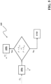
- figure 1 schematically illustrates a generic electric grid for electric power distribution applications while figures 2-5 schematically illustrate the prediction method, according to the invention.
- the present invention relates to a method 100 for predicting an electric energy consumption in an electric grid 1 ( figure1 ).
- the electric grid 1 may be of any type, for example a smart grid, a micro-grid, or an electric power distribution network for industrial, commercial, or residential buildings or plants.
- the electric grid 1 operates at low or medium voltage levels, where the term “low voltage” relates to operational voltages up to 1.2 kV AC and 1.5 kV DC and the term “medium voltage” relates to operational voltages higher than 1.2 kV AC and 1.5 kV DC up to several tens of kV, e.g., up to 72 kV AC and 100 kV DC.
- low voltage relates to operational voltages up to 1.2 kV AC and 1.5 kV DC
- intermediate voltage relates to operational voltages higher than 1.2 kV AC and 1.5 kV DC up to several tens of kV, e.g., up to 72 kV AC and 100 kV DC.
- the electric grid 1 may be of the single-phase type or multiple-phase (e.g., three-phase) type.
- the electric grid 1 can be electrically connected to one or more power sources 2 (e.g., an electric power utility) and to one or more electrical loads 3, each consuming a corresponding amount of electric energy in operation.
- power sources 2 e.g., an electric power utility
- electrical loads 3 each consuming a corresponding amount of electric energy in operation.
- the electric grid 1 may comprise one or more field devices 4 (e.g., switching devices, sensors, and the like) configured to regulate the flow of electric power along the branches of the electric grid and one or more intelligent electronic devices 5 (e.g., controllers, protection relays, smart interfaces, and the like) configured to control the operation of the above-mentioned field devices and, more generally, of the electric grid.
- field devices 4 e.g., switching devices, sensors, and the like
- intelligent electronic devices 5 e.g., controllers, protection relays, smart interfaces, and the like
- the intelligent electronic devices 5 may be equipped with suitable computing and storage resources to process data related to the operation of the electric grid.
- the intelligent electronic devices 5 are based on Edge computing architectures.
- the above-mentioned electric grid 1, the power source 2, the electrical loads 3, the field devices 4 and intelligent electronic devices 5 may be of known type and will not be here further described in details for the sake of brevity.
- the method 100 is adapted for being executed by a computerized device.
- This latter may advantageously include data processing resources capable of executing software instructions configured to implement the method.
- Such a computerized device is preferably an intelligent electronic device 5 of the electric grid, which may be installed on the field as a self-standing device (e.g., a controller) or embedded in an electrical device 4 (e.g., as a protection relay).
- an intelligent electronic device may be an intelligent switchboard HMI operatively coupled with a certain number of field devices 4 of the electric grid and configured to process data related to the operation of the electric grid.
- the method 100 provides for calculating prediction data D P related to the electric energy consumption in the electric grid by using a special mathematical model M R , which is cyclically set based on training data D T calculated by collecting and processing detection data D S1 , D S2 , D S3 related to the real-time and historical electric energy consumption in the electric grid.
- the real time detection data Dsi are continuously acquired while historical detection data D S2 , D S3 are acquired at subsequent reference instants t R , at which the above-mentioned mathematical model is set.
- the historical detection data D S2 , D S3 refer to different training time windows TW 1 , TW 2 preceding the corresponding time reference instant t R and have different selectable durations (e.g., some weeks or some months or years respectively).
- the set mathematical model M R is used to calculate prediction data related to the future electric energy consumption in the electric grid during a prediction time-window TW 3 (e.g., a week) following the reference instant t R .
- a prediction time-window TW 3 e.g., a week
- the above-mentioned prediction data D P are calculated periodically with a predefined time granularity T P (e.g., 15 minutes) and with reference to a predefined time horizon T H (e.g., 24 hours).
- a new mathematical model is set at a new reference time instant and it is used to calculate the above-mentioned prediction data during a new prediction time window following said new reference instant.
- the method 100 comprises a step 101 of acquiring first detection data D S1 including detection values related to the actual (real-time) electric energy consumption in the electric grid.
- the first detection data D S1 refer to the instantaneous energy consumption in the electric grid at each generic operation instant.
- the first detection data D S1 may be collected from one or more field devices 4 (e.g., sensors) or from one or more intelligent electronic devices 5 installed on the field or even from remote computerized devices.
- field devices 4 e.g., sensors
- intelligent electronic devices 5 installed on the field or even from remote computerized devices.
- the step 101 is continuously executed, possibly in parallel to other steps of the method 100.
- the first detection data Dsi thus include vectors of detection values, which are continuously and cyclically acquired and stored in a memory at subsequent acquisition instants, in which two consecutive acquisition instants are separated by a time interval corresponding to a predefined acquisition period of said first detection data.
- the prediction method 100 comprises one or more acquisition steps 102, 103, in which one or more sets of additional detection data D S2 , D S3 are acquired.
- Each set of additional data includes detection values related to the historical energy consumption in the electric grid during a corresponding time window TW 1 , TW 2 preceding a given reference instant t R .
- the time reference instant t R is a time instant, at which a mathematical model M R for calculating the prediction data D P related to the future electric energy consumption in the electric grid is established.
- the prediction method 100 comprises a step 102 of acquiring second detection data D S 2 including detection values related to a historical electric energy consumption in the electric grid during a first time window TW 1 preceding the reference instant t R .
- the second detection data D S 2 refer to the energy consumption in the electric grid at operation instants preceding the time reference instant t R and included in the first time window TW 1 .
- the duration of the first time window TW 1 may be selected each time the above-mentioned mathematical model is established.
- the first time window TW 1 may refer to some weeks preceding the time reference instant t R .
- the second detection data D S 2 may be acquired from a memory or from one or more intelligent electronic devices 5 installed on the field or even from remote computerized devices.
- the prediction method 100 comprises a step 103 of acquiring third detection data D S3 including detection values related to a historical electric energy consumption in the electric grid during a second time window TW 2 preceding the reference instant t R .
- the third detection data D S3 refer to the energy consumption in the electric grid at operation instants preceding the time reference instant t R and included in the second time window TW 2 .
- the duration of the second time window TW 2 is preferably very longer than the duration of the first time window TW 1 .
- the second time window TW 2 may refer to months or years preceding the time reference instant t R .
- the third detection data D S3 may be acquired from a memory or from one or more intelligent electronic devices 5 installed on the field or even from remote computerized devices.
- the prediction method 100 comprises a step 104 of acquiring calendar data D C including chronological information associated to the operation of the electric grid.
- the calendar data Dc may include information related to working days, non-working days, or holidays or, more generally, other chronological circumstances, which may influence the energy power consumption in the electric grid.
- the collected chronological information advantageously refers to a time window TW 3 following the reference instant t R .
- the calendar data D C may be acquired from a memory or from one or more intelligent electronic devices 5 installed on the field or even from remote computerized devices.
- the prediction method 100 comprises a step 105 of calculating training data D T by processing the acquired detection data and calendar data.
- the training data D T are intended to be used for setting a mathematical model describing the trend of the electric energy consumption in the electric grid during a third time window TW 3 following the reference instant t R .
- the duration of the third time window TW 3 may be varied each time the above-mentioned mathematical model is established.
- the third time window TW 3 may refer to a week following the time reference instant t R .
- the calculation step 105 includes processing the first detection data D S1 , which are continuously acquired from outer data sources, to check the correctness of the acquired data.
- the first detection data D S1 are processed by means of suitable statistical techniques to identify outlier values or missing values. Possible incorrect detection values are conveniently replaced by using suitable interpolation techniques.
- the calculation step 105 includes processing the acquired second detection data D S 2 to identify the trend of the electric energy consumption in the electric grid during the first time window TW 1 .
- the acquired second detection data D S 2 are analysed through suitable statistic techniques to identify a short-term behaviour of the electric energy consumption in the electric grid before the reference instant t R .
- the information obtained through this processing activity are conveniently used to calculate a first periodic function U(t) describing the profile of the electric energy consumption in the electric grid over the first time window WTI.
- the information obtained through this processing activity may be also used to tune appropriately the duration of the first time window TW 1 .
- the first time window T W 1 may be tuned at two weeks or four weeks preceding the reference instant t R , if the detected electric energy consumption shows a high level of periodicity or a less regular profile, respectively.
- the duration of the first time window T W 1 may be tuned depending also on the chronological information referring to said time window, which may be advantageously derived from the acquired calendar data D C .
- the calculation step 105 includes processing the acquired third detection data D S3 to identify the trend of the electric energy consumption in the electric grid during the second time window TW 2 .
- the acquired third detection data D S 2 are analysed through suitable statistic techniques to identify a long-term trend (or seasonality) of the electric energy consumption in the electric grid before the reference instant t R . This would not be possible, if only the historical detection data related to the first time window T W 1 were considered.
- the information obtained through this processing activity are conveniently used to calculate a second periodic function Ui(t) describing the profile of the electric energy consumption in the electric grid over the second time window TW 2 .
- the prediction method 100 comprises a step 106 of setting a linear auto-regressive mathematical model M R based on the calculated training data D T .
- the mathematical model M R describes the trend of the electric energy consumption in the electric grid and it is intended to be used for calculating the prediction data D P related to the electric energy consumption at instants following the reference instant t R , particularly at subsequent instants k included in the electric grid during the third time window TW 3 .
- the mathematical model M R is configured to process endogenous input values y(k) referred to a preceding instant k.
- the endogenous input values y(k) include previously calculated prediction values related to electric energy consumption in the electric grid and, possibly, also previously acquired detection values related to the instantaneous electric energy consumption in the electric grid, which are included in the first detection data D S1 .
- the mathematical model M R is configured to process one or more sets of exogenous input values U(k), U l (k).
- Each set of exogenous input values is indicative of a corresponding periodic function U(t), U l (t) approximating the profile of the electric energy consumption in the electric grid over a corresponding time window TW 1 , TW 2 preceding the reference instant t R .
- the linear auto-regressive model M R is configured to process first exogenous input values U(k) referred to an instant k preceding the reference instant t R .
- the first exogenous input values U(k) are indicative of a first periodic function U(t) approximating the profile of the electric energy consumption in the electric grid over the first time window TW 1 .
- the first periodic function U(t) is a combination of cosine and sine functions having unitary amplitude and different frequencies, for example ranging from hourly values to weekly values.
- the first periodic function U(t) is calculated based on training data obtained by processing the acquired second detection data D S 2 to identify the trend of the electric energy consumption in the electric grid during the first time window TW 1 .
- the linear auto-regressive model M R is configured to process second exogenous input values U l (k) referred to an instant k preceding the reference instant t R .
- the second exogenous input values U l (k) are indicative of a second periodic function Ui(t) approximating the profile of the electric energy consumption in the electric grid over the second time window TW 2 .
- the second periodic function Ui(t) is a combination of cosine and sine functions having unitary amplitude and different frequencies, for example ranging from monthly values to yearly values.
- the second periodic function Ui(t) is calculated based on training data obtained by processing the acquired third detection data D S3 to identify the trend of the electric energy consumption in the electric grid during the second time window TW 2 .
- the setting of the mathematical model M R is conveniently carried out during a training phase, which may include one or more training steps.
- the parameters ⁇ of the mathematical model are iteratively calculated until a maximum number of training steps is reached or the estimated error of the calculated prediction values is sufficiently low.
- the step 106 of setting the mathematical model M R conveniently comprises setting the auto-regressive order m of said mathematical model and setting the maximum number T max of training steps for training said mathematical model.
- the autoregressive order m is a parameter that may be selected depending on the desired model complexity level, or the length of the considered time windows TW i , or based on a cross-validation phase performed before the implementation of the described approach, for example on a different dataset D S0 , if available
- the maximum number T max of training steps is a parameter that may be selected depending for example on the performance of the available edge computing unit, or on possible time constraints of the considered application.
- the number of training events is T > 1.
- two following training events are advantageously separated by a time interval, which is relatively long compared to the time granularity set for calculating the prediction data D P .
- the time interval between two subsequent training events may be 24 hours.
- the linear auto-regressive mathematical model M R is a linear ARX mathematical model with one or more (more preferably multiple) exogeneous inputs.
- the training phase of the mathematical model M R is terminated if the maximum number of training steps T max is achieved or the calculated error ⁇ A i - Y i ⁇ is lower than a predefined threshold.
- one or more final parameters of the mathematical model M R are tuned based on previously calculated corresponding parameters of the mathematical model.
- the final model parameters ⁇ Ul combining the second exogenous input values input U l (k) may be calculated based on corresponding parameters ⁇ ' Ul calculated during the training phase and previously calculated corresponding parameters ⁇ " Ul (i.e., corresponding parameters of previously set mathematical models, which were obtained during previous training events).
- the tunable parameter a allows tuning the speed of adaptation of the input values (second exogenous input values), which are adapted to consider a long-term seasonality of the electric energy consumption, on the acquired detection values indicative of the instantaneous electric energy consumption of the electric grid.
- a larger value of ⁇ provides a slower adaptation as more weight is given to the contribution of the parameters calculated during preceding training events while a smaller value of ⁇ provides a faster adaptation as more weight is given to the contribution of the parameter set during the latest training event.
- the prediction method 100 comprises a step 107 of calculating the prediction data D P based on the mathematical model M R set at the preceding steps 106.
- the prediction data D P include prediction values related to the electric energy consumption in the electric grid during the third time window TW 3 .
- the prediction data D P are cyclically calculated at subsequent calculation instants k with a predefined time granularity T P (e.g, 15 minutes).
- the prediction data D P are calculated with a predefined time horizon T H (e.g, 24 hours).
- the prediction method 100 is cyclically repeated as described above at the end of each third time window TW 3 .
- steps 102-106 of the method 100 are thus repeated with reference to new time windows TW 1 , TW 2 and TW 3 calculated based on the new reference instant t R while the above-mentioned first detection data D S1 are continuously acquired (step 101 of the method 100) at each acquisition period.
- the newly set mathematical model M R is then used to calculate prediction values related to the electric energy consumption in the electric grid during a new time window TW 3 following the new reference instant t R .
- the method 100 comprises a step 108 of carrying out a first check procedure to check the computational performances of the mathematical model M R established at the reference instant t R .
- the first check procedure 108 is aimed at checking whether the prediction data D P calculated by the mathematical model M R match with corresponding detection data D S1 indicative of the actual electric energy consumption in the electric grid.
- the first check procedure 108 comprises a step 108a of comparing the first detection data Dsi and the prediction data D P , which have respectively been acquired and calculated in a time interval (checking period) between the last execution instant of the first check procedure 108 (or the reference instant t R if the check procedure is executed for the first time) and the current execution instant of the check procedure.
- a time interval checking period
- the first check procedure 108 comprises a step 108b of calculating an error function E indicative of differences between the detection values included in the collected first detection data D S1 and the prediction values included in the calculated prediction data D P .
- the error function E which may be for example a MAPE error function, provides a measure of prediction accuracy ensured by the mathematical model M R while calculating the prediction data D P .
- the check procedure 108 includes a step 108c of updating the mathematical model M R , if the above-mentioned error function E takes values exceeding a threshold error value E TH .
- the updating of the mathematical model M R is carrying out by newly executing the step 106 of the method 100, as described above.
- the mathematical model M R is updated by forcing a new training event to be carried out as described above.
- the first check procedure 108 is carried out cyclically during the third time window T W3 , for example with a checking period of 24 hours.
- the method 100 comprises a step 109 of carrying out a second check procedure to check the predicted electric energy consumption in the electric grid.
- the first check procedure 108 is aimed at checking whether the prediction data D P calculated by the mathematical model M R falls within a confidence band of prediction.
- the second check procedure 109 comprises a step 109a of processing the calculated prediction data D P to calculate a prediction function P indicative of a predicted trend of the electric energy consumption in the electric grid.
- the calculated prediction data D P may be processed by means of suitable statistical techniques of known type.
- the second check procedure 109 comprises a step 109b of generating an alert signal AL , if the prediction function P takes values higher than a predefined maximum confidence value P Max or lower than a predefined minimum confidence value P Min .
- the confidence values P max , P min may be conveniently calculated by calculating an error function indicative of differences between the detection values included in the collected first detection data D S1 and the prediction values included in the calculated prediction data D P and processing said error function by means of suitable statistical techniques of known type.
- the second check procedure 109 is terminated.
- the second check procedure 109 is carried out cyclically during the third time window T W3 , for example with a repetition period of 24 hours.
- the prediction method 100 provides relevant advantages.
- the prediction method 100 ensure high level performances in terms of prediction accuracy.
- the fine tuning of the model parameters ⁇ carried out after the completion of the training phase, particularly of the parameters ⁇ Ul intended to model the long-term seasonality of the electric energy consumption, further improves the performances provided by the prediction method 100.
- the iterative checking of the accuracy of the calculated prediction data further improves the reliability of the prediction method.
- the prediction method 100 is configured to process relatively small sets of data. Therefore, it is particularly adapted for being implemented in computing systems having limited computational and data storage resources, for example in Edge computing systems commonly-used for managing the operation of electric grids.
- the prediction method 100 is thus particularly adapted to be implemented using the hardware and software resources already installed on the field to manage the operation of an electric grid.
- the prediction method 100 is thus adapted for being implemented in digitally enabled power distribution networks (smart grids, micro-grids and the like).
Landscapes
- Engineering & Computer Science (AREA)
- Business, Economics & Management (AREA)
- Human Resources & Organizations (AREA)
- Economics (AREA)
- Strategic Management (AREA)
- Physics & Mathematics (AREA)
- General Physics & Mathematics (AREA)
- Entrepreneurship & Innovation (AREA)
- Theoretical Computer Science (AREA)
- Tourism & Hospitality (AREA)
- Marketing (AREA)
- General Business, Economics & Management (AREA)
- Quality & Reliability (AREA)
- Operations Research (AREA)
- Game Theory and Decision Science (AREA)
- Development Economics (AREA)
- Educational Administration (AREA)
- Power Engineering (AREA)
- Health & Medical Sciences (AREA)
- Data Mining & Analysis (AREA)
- Automation & Control Theory (AREA)
- Bioinformatics & Cheminformatics (AREA)
- Primary Health Care (AREA)
- Life Sciences & Earth Sciences (AREA)
- Artificial Intelligence (AREA)
- General Health & Medical Sciences (AREA)
- Water Supply & Treatment (AREA)
- Public Health (AREA)
- Evolutionary Computation (AREA)
- Bioinformatics & Computational Biology (AREA)
- Computer Vision & Pattern Recognition (AREA)
- Evolutionary Biology (AREA)
- General Engineering & Computer Science (AREA)
- Supply And Distribution Of Alternating Current (AREA)
Abstract
Description
- The present invention relates to the field of electric power distribution grids. More particularly, the present invention relates to a method for predicting electric energy consumption in an electric grid.
- As is known, the management of electric grids generally requires an accurate prediction activity of the electric energy consumption to allow system operators to properly plan the use of electric energy over time, thereby preventing or limiting demand peaks and making more favourable purchase plans of electric energy.
- Most common forecast methods are based on machine learning (ML) techniques and require that relevant amounts of data are processed to provide accurate predictions. Additionally, these methods typically provide for carrying out a computationally intensive training phase of an artificial intelligence unit (e.g., a neural network) executing the ML algorithms. ML-based prediction methods can thus be hardly implemented by computing systems typically managing the operation of field devices and switchboards in electric grids, which often have relatively limited storage and computational resources unsuitable to process huge amounts of data. These computing systems are, in fact, commonly based on Edge computing architectures and are basically aimed at bringing computation and data storage closer to the sources of data to improve response times and save bandwidth rather than processing large datasets.
- In the state of the art, there have been developed prediction methods (e.g., based on linear regression analysis techniques), which normally require lighter computational and data storage resources compared to ML-based forecast methods and which would therefore be adapted for being implemented computing systems commonly used to manage electric grids.
- An example of these prediction methods is described in
US10515308B2 - However, available prediction methods of this type often provide relatively poor performances in terms of reliability and prediction accuracy compared to ML-based prediction techniques. The main task of the present invention is to provide to a method for predicting electric energy consumption in an electric grid, which can overcome the limitations of the prior art highlighted above.
- Within this aim, another purpose of the present invention is to provide a prediction method, which can ensure high level performances in terms of reliability and prediction accuracy.
- A further aim of the invention is to provide a prediction method, which can be easily implemented even when limited computational and data storage resources are available and which is therefore suitable for being implemented in computing systems commonly used for managing the operation of electric grids, for example in computing systems based on Edge computing architectures.
- This task and these aims, as well as other aims that will appear evident from the subsequent description and from the attached drawings, are achieved, according to the invention, by a prediction method, according to
claim 1 and to the related dependent claims proposed below. - In a general definition, the method, according to the invention, comprises the following steps:
- acquiring first detection data including detection values related to an actual electric energy consumption in said electric grid;
- acquiring additional detection data including detection values related to the energy consumption in said electric grid during at least a time window preceding a given reference instant;
- acquiring calendar data including chronological information associated to the operation of said electric grid;
- calculating training data based on the acquired detection data and calendar data;
- based on said training data, setting a linear auto-regressive mathematical model describing the trend of the electric energy consumption in said electric grid. Such a linear auto-regressive mathematical model is configured to process at least a set of exogenous input values indicative of at least a periodic function approximating the profile of the electric energy consumption in said electric grid over said at least a time window preceding said reference instant;
- based on said linear auto-regressive model, calculating prediction data including prediction values related to the electric energy consumption in said electric grid during a time window following said reference instant.
- Preferably, the method according to the invention comprises the step of acquiring second detection data including detection values related to the energy consumption in said electric grid during a first time window preceding said reference instant. In this case, the linear auto-regressive mathematical model is configured to process first exogenous input values indicative of a first periodic function approximating the profile of the electric energy consumption in said electric grid over said first time window.
- Preferably, the method according to the invention comprises also the step of acquiring third detection data including detection values related to the energy consumption in said electric grid during a second time window preceding said reference instant. In this case, the linear auto-regressive mathematical model is configured to process second exogenous input values indicative of a second periodic function approximating the profile of the electric energy consumption in said electric grid over said second time window. Preferably, such a second time window is longer than said first time window.
- Further characteristics and advantages of the present invention shall emerge more clearly from the description of preferred but not exclusive embodiments illustrated purely by way of example and without limitation in the attached drawings, in which
figure 1 schematically illustrates a generic electric grid for electric power distribution applications whilefigures 2-5 schematically illustrate the prediction method, according to the invention. - With reference to the mentioned figures, the present invention relates to a method 100 for predicting an electric energy consumption in an electric grid 1 (
figure1 ). - In principle, the
electric grid 1 may be of any type, for example a smart grid, a micro-grid, or an electric power distribution network for industrial, commercial, or residential buildings or plants. - Preferably, the
electric grid 1 operates at low or medium voltage levels, where the term "low voltage" relates to operational voltages up to 1.2 kV AC and 1.5 kV DC and the term "medium voltage" relates to operational voltages higher than 1.2 kV AC and 1.5 kV DC up to several tens of kV, e.g., up to 72 kV AC and 100 kV DC. - The
electric grid 1 may be of the single-phase type or multiple-phase (e.g., three-phase) type. In general terms, theelectric grid 1 can be electrically connected to one or more power sources 2 (e.g., an electric power utility) and to one or moreelectrical loads 3, each consuming a corresponding amount of electric energy in operation. - The
electric grid 1 may comprise one or more field devices 4 (e.g., switching devices, sensors, and the like) configured to regulate the flow of electric power along the branches of the electric grid and one or more intelligent electronic devices 5 (e.g., controllers, protection relays, smart interfaces, and the like) configured to control the operation of the above-mentioned field devices and, more generally, of the electric grid. - Advantageously, the intelligent electronic devices 5 may be equipped with suitable computing and storage resources to process data related to the operation of the electric grid.
- Preferably, the intelligent electronic devices 5 are based on Edge computing architectures.
- In general, the above-mentioned
electric grid 1, thepower source 2, theelectrical loads 3, the field devices 4 and intelligent electronic devices 5 may be of known type and will not be here further described in details for the sake of brevity. - The method 100, according to the invention, is adapted for being executed by a computerized device. This latter may advantageously include data processing resources capable of executing software instructions configured to implement the method.
- Such a computerized device is preferably an intelligent electronic device 5 of the electric grid, which may be installed on the field as a self-standing device (e.g., a controller) or embedded in an electrical device 4 (e.g., as a protection relay). As an example, such an intelligent electronic device may be an intelligent switchboard HMI operatively coupled with a certain number of field devices 4 of the electric grid and configured to process data related to the operation of the electric grid.
- As it will be better explained in the following, the method 100 provides for calculating prediction data DP related to the electric energy consumption in the electric grid by using a special mathematical model MR , which is cyclically set based on training data DT calculated by collecting and processing detection data DS1, DS2, DS3 related to the real-time and historical electric energy consumption in the electric grid.
- Referring to
figure 2 , the real time detection data Dsi are continuously acquired while historical detection data DS2, DS3 are acquired at subsequent reference instants tR , at which the above-mentioned mathematical model is set. The historical detection data DS2, DS3 refer to different training time windows TW1 , TW2 preceding the corresponding time reference instant tR and have different selectable durations (e.g., some weeks or some months or years respectively). - Once it is set at the corresponding reference instant tR , the set mathematical model MR is used to calculate prediction data related to the future electric energy consumption in the electric grid during a prediction time-window TW3 (e.g., a week) following the reference instant tR . During the above-mentioned prediction time window TW3, the above-mentioned prediction data DP are calculated periodically with a predefined time granularity TP (e.g., 15 minutes) and with reference to a predefined time horizon TH (e.g., 24 hours).
- At the end of the prediction time-window TW 3, a new mathematical model is set at a new reference time instant and it is used to calculate the above-mentioned prediction data during a new prediction time window following said new reference instant.
- The prediction method 100, according to the invention, will now be described in details. Referring to
figures 2-3 , the method 100 comprises astep 101 of acquiring first detection data DS1 including detection values related to the actual (real-time) electric energy consumption in the electric grid. - The first detection data DS1 refer to the instantaneous energy consumption in the electric grid at each generic operation instant.
- The first detection data DS1 may be collected from one or more field devices 4 (e.g., sensors) or from one or more intelligent electronic devices 5 installed on the field or even from remote computerized devices.
- Preferably, the
step 101 is continuously executed, possibly in parallel to other steps of the method 100. The first detection data Dsi thus include vectors of detection values, which are continuously and cyclically acquired and stored in a memory at subsequent acquisition instants, in which two consecutive acquisition instants are separated by a time interval corresponding to a predefined acquisition period of said first detection data. - According to the invention, the prediction method 100 comprises one or
more acquisition steps - Each set of additional data includes detection values related to the historical energy consumption in the electric grid during a corresponding time window TW1, TW2 preceding a given reference instant tR . As it is explained above, the time reference instant tR is a time instant, at which a mathematical model MR for calculating the prediction data DP related to the future electric energy consumption in the electric grid is established.
- Preferably, the prediction method 100 comprises a
step 102 of acquiring second detection data D S2 including detection values related to a historical electric energy consumption in the electric grid during a first time window TW1 preceding the reference instant tR . - The second detection data D S2 refer to the energy consumption in the electric grid at operation instants preceding the time reference instant tR and included in the first time window TW1 . The duration of the first time window TW1 may be selected each time the above-mentioned mathematical model is established. As an example, the first time window TW1 may refer to some weeks preceding the time reference instant tR .
- The second detection data D S2 may be acquired from a memory or from one or more intelligent electronic devices 5 installed on the field or even from remote computerized devices. Preferably, the prediction method 100 comprises a
step 103 of acquiring third detection data DS3 including detection values related to a historical electric energy consumption in the electric grid during a second time window TW2 preceding the reference instant tR . - The third detection data DS3 refer to the energy consumption in the electric grid at operation instants preceding the time reference instant tR and included in the second time window TW2. The duration of the second time window TW2 is preferably very longer than the duration of the first time window TW1. As an example, the second time window TW2 may refer to months or years preceding the time reference instant tR .
- The third detection data DS3 may be acquired from a memory or from one or more intelligent electronic devices 5 installed on the field or even from remote computerized devices. According to the invention, the prediction method 100 comprises a
step 104 of acquiring calendar data DC including chronological information associated to the operation of the electric grid. The calendar data Dc may include information related to working days, non-working days, or holidays or, more generally, other chronological circumstances, which may influence the energy power consumption in the electric grid. - The collected chronological information advantageously refers to a time window TW3 following the reference instant tR .
- The calendar data DC may be acquired from a memory or from one or more intelligent electronic devices 5 installed on the field or even from remote computerized devices.
- According to the invention, the prediction method 100 comprises a
step 105 of calculating training data DT by processing the acquired detection data and calendar data. - The training data DT are intended to be used for setting a mathematical model describing the trend of the electric energy consumption in the electric grid during a third time window TW3 following the reference instant tR .
- In principle, the duration of the third time window TW3 may be varied each time the above-mentioned mathematical model is established. As an example, the third time window TW3 may refer to a week following the time reference instant tR .
- Preferably, the
calculation step 105 includes processing the first detection data DS1, which are continuously acquired from outer data sources, to check the correctness of the acquired data. Advantageously, the first detection data DS1 are processed by means of suitable statistical techniques to identify outlier values or missing values. Possible incorrect detection values are conveniently replaced by using suitable interpolation techniques. - Preferably, the
calculation step 105 includes processing the acquired second detection data D S2 to identify the trend of the electric energy consumption in the electric grid during the first time window TW1. In practice, the acquired second detection data D S2 are analysed through suitable statistic techniques to identify a short-term behaviour of the electric energy consumption in the electric grid before the reference instant tR . - As it will be more apparent from the following, the information obtained through this processing activity are conveniently used to calculate a first periodic function U(t) describing the profile of the electric energy consumption in the electric grid over the first time window WTI.
- This allows setting the above-mentioned mathematical model MR in such a way to consider possible short-term non-linearities influencing the electric energy consumption in the electric grid.
- The information obtained through this processing activity may be also used to tune appropriately the duration of the first time window TW1.
- As an example, the first time window TW 1 may be tuned at two weeks or four weeks preceding the reference instant tR , if the detected electric energy consumption shows a high level of periodicity or a less regular profile, respectively.
- Advantageously, the duration of the first time window TW 1 may be tuned depending also on the chronological information referring to said time window, which may be advantageously derived from the acquired calendar data DC.
- Preferably, the
calculation step 105 includes processing the acquired third detection data DS3 to identify the trend of the electric energy consumption in the electric grid during the second time window TW2. In practice, the acquired third detection data D S2 are analysed through suitable statistic techniques to identify a long-term trend (or seasonality) of the electric energy consumption in the electric grid before the reference instant tR . This would not be possible, if only the historical detection data related to the first time window TW 1 were considered. - As it will be more apparent from the following, the information obtained through this processing activity are conveniently used to calculate a second periodic function Ui(t) describing the profile of the electric energy consumption in the electric grid over the second time window TW2.
- This allows setting the above-mentioned mathematical model in such a way to consider possible long-term non-linearities or seasonal factors influencing the electric energy consumption in the electric grid.
- According to the invention, the prediction method 100 comprises a
step 106 of setting a linear auto-regressive mathematical model MR based on the calculated training data DT. - The mathematical model MR describes the trend of the electric energy consumption in the electric grid and it is intended to be used for calculating the prediction data DP related to the electric energy consumption at instants following the reference instant tR , particularly at subsequent instants k included in the electric grid during the third time window TW3.
- As it has an auto-regressive nature, at each instant k+1, the mathematical model MR is configured to process endogenous input values y(k) referred to a preceding instant k.
- The endogenous input values y(k) include previously calculated prediction values related to electric energy consumption in the electric grid and, possibly, also previously acquired detection values related to the instantaneous electric energy consumption in the electric grid, which are included in the first detection data DS1.
- According to a particularly important aspect of the invention, however, the mathematical model MR is configured to process one or more sets of exogenous input values U(k), Ul(k).
- Each set of exogenous input values is indicative of a corresponding periodic function U(t), Ul(t) approximating the profile of the electric energy consumption in the electric grid over a corresponding time window TW 1, TW2 preceding the reference instant tR .
- Preferably, the linear auto-regressive model MR is configured to process first exogenous input values U(k) referred to an instant k preceding the reference instant tR .
- The first exogenous input values U(k) are indicative of a first periodic function U(t) approximating the profile of the electric energy consumption in the electric grid over the first time window TW1.
- Preferably, the first periodic function U(t) is a combination of cosine and sine functions having unitary amplitude and different frequencies, for example ranging from hourly values to weekly values. Advantageously, the first periodic function U(t) is calculated based on training data obtained by processing the acquired second detection data D S2 to identify the trend of the electric energy consumption in the electric grid during the first time window TW1.
- A vector of first exogenous input values U(k) at a generic instant k preceding the reference instant tR may thus be expressed as the combination of n sinusoidal terms according to the following expression:

- Preferably, the linear auto-regressive model MR is configured to process second exogenous input values Ul(k) referred to an instant k preceding the reference instant tR .
- The second exogenous input values Ul(k) are indicative of a second periodic function Ui(t) approximating the profile of the electric energy consumption in the electric grid over the second time window TW2.
- Preferably, the second periodic function Ui(t) is a combination of cosine and sine functions having unitary amplitude and different frequencies, for example ranging from monthly values to yearly values.
- Advantageously, the second periodic function Ui(t) is calculated based on training data obtained by processing the acquired third detection data DS3 to identify the trend of the electric energy consumption in the electric grid during the second time window TW2.
- A vector of second exogenous input values Ul(k) at a generic instant k preceding the reference instant tR may thus be expressed as the combination of q sinusoidal terms according to the following expression:

- The setting of the mathematical model MR is conveniently carried out during a training phase, which may include one or more training steps.
- At each training event, the parameters θ of the mathematical model are iteratively calculated until a maximum number of training steps is reached or the estimated error of the calculated prediction values is sufficiently low.
- The
step 106 of setting the mathematical model MR conveniently comprises setting the auto-regressive order m of said mathematical model and setting the maximum number Tmax of training steps for training said mathematical model. - The autoregressive order m is a parameter that may be selected depending on the desired model complexity level, or the length of the considered time windows TWi , or based on a cross-validation phase performed before the implementation of the described approach, for example on a different dataset DS0, if available
- As an example, the autoregressive order m may be set as m =3.
- The maximum number Tmax of training steps is a parameter that may be selected depending for example on the performance of the available edge computing unit, or on possible time constraints of the considered application.
- Preferably, the number of training events is T > 1. In this case, two following training events are advantageously separated by a time interval, which is relatively long compared to the time granularity set for calculating the prediction data DP. For example, if a time granularity of 15 minutes is set, the time interval between two subsequent training events may be 24 hours. Preferably, the linear auto-regressive mathematical model MR is a linear ARX mathematical model with one or more (more preferably multiple) exogeneous inputs.
- In general terms, the mathematical model MR may thus be expressed as:

- y(k) is a vector of endogenous input values. For k <= 2m, y(k) includes both previously calculated prediction values and real-time detection values included in the first detection data DS1 while y(k) includes only previously calculated prediction values for k > 2m;
- U(k) is a vector of first exogenous input values indicative of a first periodic function U(t) approximating the profile of the electric energy consumption in the electric grid over the first time window TW 1;
- Ul(k) is a vector of second exogenous input values indicative of a second periodic function Ui(t) approximating the profile of the electric energy consumption in the electric grid over the second time window TW2,
- θ is a vector of model parameters to be calculated during the training phase of the mathematical model;
- TH is the time horizon set for calculating the prediction data DP. As an example, TH may be set as TH = 24 hours;
- TP is the time granularity set for calculating the prediction data DP. As an example, TP may be set as TP = 15 minutes.
- The ratio TH /TP defines the number of prediction and detection values to be considered for calculating the prediction error. As an example, the ratio takes a value TH /TP = 96 with a time horizon TH set at 24 hours and a time granularity TP set at 15 minutes.
- At each training event, a preliminary vector θ' of model parameters is calculated by solving the unconstrained linear problem:

- Tis the number representing the elapsed time (preferably counted in days) up to the training event and during which the first detection data DS1 have been collected;
- Ai is a vector of (TH /TP - m) detection values included in a time unit i (preferably a day i), during which the first detection data DS1 have been collected, where m is the set number of regression steps. As an example, the vector Ai has (96-m) values with a time horizon TH set at 24 hours and a time granularity TP set at 15 minutes;
- Yi is a vector of (TH /TP - m) prediction values calculated for a time unit i (preferably a day i), during which the detection data Dsi have been collected. As an example, the vector Yi has (96-m) values with a time horizon TH set at 24 hours and a time granularity TP set at 15 minutes.
- The training phase of the mathematical model MR is terminated if the maximum number of training steps Tmax is achieved or the calculated error∥ Ai - Yi ∥ is lower than a predefined threshold.
- At the end of the training phase, the last calculated vector θ' of model parameters becomes the final vector θ of model parameters of the mathematical model. The mathematical model MR is thus finally set.
- The final vector of model parameters θ may be expressed as:

- θy is a vector of calculated model parameters linearly combining the endogenous input values input y (k);
- θ U is a vector of calculated model parameters linearly combining the first exogenous input values input U(k);
- θ Ul is a vector of calculated model parameters linearly combining the second exogenous input values input Ul(k).
- According to an aspect of the invention, one or more final parameters of the mathematical model MR are tuned based on previously calculated corresponding parameters of the mathematical model.
- In particular, the final model parameters θ Ul combining the second exogenous input values input U l(k) may be calculated based on corresponding parameters θ'Ul calculated during the training phase and previously calculated corresponding parameters θ"Ul (i.e., corresponding parameters of previously set mathematical models, which were obtained during previous training events). The vector θ Ul of final model parameters combining the second exogenous input values input Ul(k) may be calculated as:

- θ'Ul is a vector of corresponding parameters calculated during the latest training event;
- θ'Ul is a vector of corresponding parameters calculated during a previous training event;
- α is a tunable parameter, with 0 < a < = 1.
- The tunable parameter a allows tuning the speed of adaptation of the input values (second exogenous input values), which are adapted to consider a long-term seasonality of the electric energy consumption, on the acquired detection values indicative of the instantaneous electric energy consumption of the electric grid.
- A larger value of α provides a slower adaptation as more weight is given to the contribution of the parameters calculated during preceding training events while a smaller value of α provides a faster adaptation as more weight is given to the contribution of the parameter set during the latest training event.
- According to the invention, the prediction method 100 comprises a
step 107 of calculating the prediction data DP based on the mathematical model MR set at the precedingsteps 106. - The prediction data DP include prediction values related to the electric energy consumption in the electric grid during the third time window TW3.
- As shown above, preferably, the prediction data DP are cyclically calculated at subsequent calculation instants k with a predefined time granularity TP (e.g, 15 minutes).
- Preferably, at each calculation instant k, the prediction data DP are calculated with a predefined time horizon TH (e.g, 24 hours).
- Preferably, the prediction method 100 is cyclically repeated as described above at the end of each third time window TW3.
- When third time window TW3 expires, a new linear auto-regressive mathematical MR model is set at a new reference instant tR .
- The above-described steps 102-106 of the method 100 are thus repeated with reference to new time windows TW1 , TW2 and TW3 calculated based on the new reference instant tR while the above-mentioned first detection data DS1 are continuously acquired (step 101 of the method 100) at each acquisition period.
- The newly set mathematical model MR is then used to calculate prediction values related to the electric energy consumption in the electric grid during a new time window TW3 following the new reference instant tR .
- According to an aspect of the invention (
figures 3-4 ), the method 100 comprises astep 108 of carrying out a first check procedure to check the computational performances of the mathematical model MR established at the reference instant tR . - The
first check procedure 108 is aimed at checking whether the prediction data DP calculated by the mathematical model MR match with corresponding detection data DS1 indicative of the actual electric energy consumption in the electric grid. - Preferably, the
first check procedure 108 comprises astep 108a of comparing the first detection data Dsi and the prediction data DP, which have respectively been acquired and calculated in a time interval (checking period) between the last execution instant of the first check procedure 108 (or the reference instant tR if the check procedure is executed for the first time) and the current execution instant of the check procedure. - Preferably, the
first check procedure 108 comprises astep 108b of calculating an error function E indicative of differences between the detection values included in the collected first detection data DS1 and the prediction values included in the calculated prediction data DP . - The error function E, which may be for example a MAPE error function, provides a measure of prediction accuracy ensured by the mathematical model MR while calculating the prediction data DP.
- The
check procedure 108 includes astep 108c of updating the mathematical model MR, if the above-mentioned error function E takes values exceeding a threshold error value ETH. - The updating of the mathematical model MR is carrying out by newly executing the
step 106 of the method 100, as described above. In practice, the mathematical model MR is updated by forcing a new training event to be carried out as described above. - If the above-mentioned error function E takes values, which do not exceed the threshold error value ETH, the mathematical model MR is maintained and the
first check procedure 108 is terminated. - Preferably, the
first check procedure 108 is carried out cyclically during the third time window TW3, for example with a checking period of 24 hours. - According to another aspect of the invention (
figures 3 and5 ), the method 100 comprises astep 109 of carrying out a second check procedure to check the predicted electric energy consumption in the electric grid. - The
first check procedure 108 is aimed at checking whether the prediction data DP calculated by the mathematical model MR falls within a confidence band of prediction. - Preferably, the
second check procedure 109 comprises astep 109a of processing the calculated prediction data DP to calculate a prediction function P indicative of a predicted trend of the electric energy consumption in the electric grid. - In order to calculate the prediction function P, the calculated prediction data DP may be processed by means of suitable statistical techniques of known type.
- Preferably, the
second check procedure 109 comprises astep 109b of generating an alert signal AL, if the prediction function P takes values higher than a predefined maximum confidence value PMax or lower than a predefined minimum confidence value PMin. - The confidence values Pmax, Pmin may be conveniently calculated by calculating an error function indicative of differences between the detection values included in the collected first detection data DS1 and the prediction values included in the calculated prediction data DP and processing said error function by means of suitable statistical techniques of known type.
- If the above-mentioned prediction function P takes values within the confidence band defined by the confidence values Pmax, Pmin, the
second check procedure 109 is terminated. Preferably, thesecond check procedure 109 is carried out cyclically during the third time window TW3 , for example with a repetition period of 24 hours. - The prediction method 100, according to the present invention, provides relevant advantages. The prediction method 100 ensure high level performances in terms of prediction accuracy.
- The circumstance that the linear auto-regressive model MR is configured to process both first and second exogenous input values U(k), Ul(k) is particularly relevant from this point of view. This solution, in fact, allows remarkably improving the prediction accuracy as short-term and long-term factors, which may influence the trend of the electric energy consumption, are duly considered while calculating the prediction data DP.
- The fine tuning of the model parameters θ carried out after the completion of the training phase, particularly of the parameters θ Ul intended to model the long-term seasonality of the electric energy consumption, further improves the performances provided by the prediction method 100.
- The iterative checking of the accuracy of the calculated prediction data further improves the reliability of the prediction method.
- In confirmation of the above, experimental tests have shown that the prediction method 100 ensures accuracy performances fully comparable with the accuracy performances provided by the known methods of the state of the art based on ML algorithms.
- The prediction method 100 is configured to process relatively small sets of data. Therefore, it is particularly adapted for being implemented in computing systems having limited computational and data storage resources, for example in Edge computing systems commonly-used for managing the operation of electric grids.
- The prediction method 100 is thus particularly adapted to be implemented using the hardware and software resources already installed on the field to manage the operation of an electric grid. The prediction method 100 is thus adapted for being implemented in digitally enabled power distribution networks (smart grids, micro-grids and the like).
Claims (17)
- Method (100) for predicting electric energy consumption in an electric grid (1), said method being characterised by the following steps:- acquiring (101) first detection data (DS1 ) including detection values related to an actual electric energy consumption in said electric grid;- acquiring (102, 103) additional detection data (DS2 , DS3 ) including detection values related to the energy consumption in said electric grid during at least a time window (TW1, TW2 ) preceding a reference instant (tR );- acquiring (104) calendar data (DC ) including chronological information associated to the operation of said electric grid;- calculating (105) training data (DT ) based on the acquired detection data and calendar data;- based on said training data (DT ), setting (106) a linear auto-regressive mathematical model (MR ) describing the trend of the electric energy consumption in said electric grid, said linear auto-regressive mathematical model (MR ) being configured to process at least a set of exogenous input values (U(k), Ul(k)) indicative of at least a periodic function (U(t), Ul(t)) approximating the profile of the electric energy consumption in said electric grid over said at least a time window (TW1, TW2 ) preceding said reference instant (tR );- based on said linear auto-regressive model (MR ), calculating (107) prediction data (DP ) including prediction values related to the electric energy consumption in said electric grid during a time window (TW3 ) following said reference instant (tR ).
- Method, according to claim 1, characterised in that it comprises the step of acquiring (102) second detection data (DS2 ) including detection values related to the energy consumption in said electric grid during a first time window (TW1 ) preceding said reference instant (tR ), wherein said linear auto-regressive mathematical model (MR ) is configured to process first exogenous input values (U(k)) indicative of a first periodic function (U(t)) approximating the profile of the electric energy consumption in said electric grid over said first time window (TW1 ).
- Method, according to one of the previous claims, characterised in that it comprises the step of acquiring (103) third detection data (DS3 ) including detection values related to the energy consumption in said electric grid during a second time window (TW2 ) preceding said reference instant (tR ), wherein said linear auto-regressive mathematical model (MR ) is configured to process second exogenous input values (Ul(k)) indicative of a second periodic function (Ul(t)) approximating the profile of the electric energy consumption in said electric grid over said second time window (TW2 ).
- Method, according to one of the previous claims, characterised in that the step (105) of calculating said training data (DT ) includes processing the acquired first detection data (DS1 ) to check the correctness of said data.
- Method, according to claim 2, characterised in that the step (105) of calculating said training data (DT ) includes processing the acquired second detection data (DS2 ) to identify the trend of the electric energy consumption in the electric grid during the first time window (TW1 ).
- Method, according to claim 3, characterised in that the step (105) of calculating said training data (DT ) includes processing the acquired third detection data (DS3 ) to identify the trend of the electric energy consumption in the electric grid during the second time window (TW2 ).
- Method, according to one of the previous claims, characterised in that said prediction data (DP ) are cyclically calculated with a predefined time granularity (TP ) and with a predefined time horizon (TH ).
- Method, according to one of the previous claims, characterised in that said linear auto-regressive mathematical model (MR ) is a linear ARX mathematical model with one or more exogeneous inputs.
- Method, according to one of the previous claims, characterised in that setting said linear auto-regressive mathematical model (MR ) includes:- setting a regression order (m) and a maximum number (Tmax ) of training steps for said linear auto-regressive mathematical model (MR );- iteratively calculating one or more parameters ( θ ) of said linear auto-regressive mathematical model (MR ) based on said training data (DT ) during said training steps by solving an unconstrained linear problem established basing on the set regression order (m) and maximum number (Tmax ) of training steps.
- Method, according to one of the previous claims, characterised in that setting said linear auto-regressive mathematical model (MR ) includes tuning one or more parameters ( θUl ) of said linear auto-regressive model (MR ) based on corresponding parameters ( θ'Ul ) calculated during said training steps and one or more parameters ( θ'Ul ) calculated for previously set linear auto-regressive mathematical models (MR ).
- Method, according to one of the previous claims, characterised in that it comprises the step (108) of carrying out a first check procedure to check the computational performances of said mathematical model.
- Method, according to claim 11, characterised in that said first check procedure (108) comprises:- comparing (108a) the first detection data (DS1 ) acquired during a predefined checking period and the prediction data (DP ) calculated during said checking interval;- calculating (108b) an error function (E) indicative of differences between the detection values included in said first detection data (DS1 ) and the prediction values included in said prediction data (DP );- updating (108c) said auto-regressive mathematical model (MR ), if said error function (E) takes values exceeding a threshold error value (ETH ).
- Method, according to one of the previous claims, characterised in that it comprises the step (109) of carrying out a second check procedure to check the electric energy consumption predicted by said mathematical model.
- Method, according to claim 13, characterised in that said second check procedure (109) comprises:- processing (109a) the calculated prediction data (DP ) to calculate a prediction function (P) indicative of a predicted trend of the electric energy consumption in said electric grid;- generating (109b) an alert signal, if said prediction function (P) takes values higher a maximum confidence value (Pmax ) or lower than a minimum confidence value (Pmin).
- A computer program, which is stored or storable in a storage medium, characterised in that it comprises software instructions to implement a method (100), according to one or more of the previous claims.
- A computerized device characterised in that it comprises data processing resources configured to execute software instructions to implement a method (100), according to one or more of the claims from 1 to 14.
- A computerised device, according to claim 16, characterised in that it is an intelligent electronic device (5) for an electric power distribution grid (1).
Priority Applications (3)
| Application Number | Priority Date | Filing Date | Title |
|---|---|---|---|
| EP23210163.4A EP4557187B1 (en) | 2023-11-15 | 2023-11-15 | A method for predicting electric energy consumption in an electric grid |
| CN202411590630.9A CN120016428A (en) | 2023-11-15 | 2024-11-08 | Method for predicting electrical energy consumption in an electric network |
| US18/946,350 US20250155861A1 (en) | 2023-11-15 | 2024-11-13 | Method for predicting electric energy consumption in an electric grid |
Applications Claiming Priority (1)
| Application Number | Priority Date | Filing Date | Title |
|---|---|---|---|
| EP23210163.4A EP4557187B1 (en) | 2023-11-15 | 2023-11-15 | A method for predicting electric energy consumption in an electric grid |
Publications (2)
| Publication Number | Publication Date |
|---|---|
| EP4557187A1 true EP4557187A1 (en) | 2025-05-21 |
| EP4557187B1 EP4557187B1 (en) | 2026-05-06 |
Family
ID=88837420
Family Applications (1)
| Application Number | Title | Priority Date | Filing Date |
|---|---|---|---|
| EP23210163.4A Active EP4557187B1 (en) | 2023-11-15 | 2023-11-15 | A method for predicting electric energy consumption in an electric grid |
Country Status (3)
| Country | Link |
|---|---|
| US (1) | US20250155861A1 (en) |
| EP (1) | EP4557187B1 (en) |
| CN (1) | CN120016428A (en) |
Families Citing this family (2)
| Publication number | Priority date | Publication date | Assignee | Title |
|---|---|---|---|---|
| CN120474104B (en) * | 2025-05-20 | 2026-02-13 | 深圳市深鹏达电网科技有限公司 | Energy scheduling and energy saving optimization method for smart power grid |
| CN121212847A (en) * | 2025-09-29 | 2025-12-26 | 朋熙半导体科技(北京)有限公司 | Methods, systems, devices and media for predicting power grid energy consumption in semiconductor factories |
Citations (2)
| Publication number | Priority date | Publication date | Assignee | Title |
|---|---|---|---|---|
| US10515308B2 (en) | 2015-10-30 | 2019-12-24 | Global Design Corporation Ltd. | System, method and cloud-based platform for predicting energy consumption |
| US11416936B1 (en) * | 2019-06-05 | 2022-08-16 | Form Energy, Inc. | Systems and methods for managing a renewable power asset |
-
2023
- 2023-11-15 EP EP23210163.4A patent/EP4557187B1/en active Active
-
2024
- 2024-11-08 CN CN202411590630.9A patent/CN120016428A/en active Pending
- 2024-11-13 US US18/946,350 patent/US20250155861A1/en active Pending
Patent Citations (2)
| Publication number | Priority date | Publication date | Assignee | Title |
|---|---|---|---|---|
| US10515308B2 (en) | 2015-10-30 | 2019-12-24 | Global Design Corporation Ltd. | System, method and cloud-based platform for predicting energy consumption |
| US11416936B1 (en) * | 2019-06-05 | 2022-08-16 | Form Energy, Inc. | Systems and methods for managing a renewable power asset |
Non-Patent Citations (1)
| Title |
|---|
| DAVIDE ANGUITA ET AL: "Long-term energy load forecasting using Auto-Regressive and approximating Support Vector Regression", ENERGY CONFERENCE AND EXHIBITION (ENERGYCON), 2012 IEEE INTERNATIONAL, IEEE, 9 September 2012 (2012-09-09), pages 842 - 847, XP032466790, ISBN: 978-1-4673-1453-4, DOI: 10.1109/ENERGYCON.2012.6348269 * |
Also Published As
| Publication number | Publication date |
|---|---|
| EP4557187B1 (en) | 2026-05-06 |
| CN120016428A (en) | 2025-05-16 |
| US20250155861A1 (en) | 2025-05-15 |
Similar Documents
| Publication | Publication Date | Title |
|---|---|---|
| US20250155861A1 (en) | Method for predicting electric energy consumption in an electric grid | |
| Dang-Ha et al. | Local short term electricity load forecasting: Automatic approaches | |
| US20200350766A1 (en) | System and method for optimal control of energy storage system | |
| EP3451479A1 (en) | System and method for distribution load forecasting in a power grid | |
| Sheshadri | Electrical load forecasting using time series analysis | |
| US10734809B2 (en) | Energy monitoring system | |
| US12444973B2 (en) | Energy disaggregation methods and systems using weather data | |
| Lin et al. | Event-triggered load frequency control based on age-of-information | |
| Marrero et al. | An application of load forecasting based on ARIMA models and particle swarm optimization | |
| US12130778B2 (en) | Method and device for facilitating storage of data from an industrial automation control system or power system | |
| Nassif | Short term power demand prediction using stochastic gradient boosting | |
| WO2024184286A1 (en) | Method and processing system for processing data related to a power grid, and system comprising a power grid | |
| Sharma et al. | An Experimental Study for Comparing Different Method for Time Series Forecasting Prediction & Anomaly Detection | |
| Kisku et al. | Optimization and leveraging of peak demand using lstm and fuzzy logic approaches in demand-side management | |
| Pawłowski et al. | Lagrange interpolation for signal reconstruction in event-based GPC | |
| Netsanet et al. | Short term load forecasting using wavelet augmented non-linear autoregressive neural networks: A single customer level perspective | |
| Arabali et al. | Short-term electricity price forecasting | |
| Clairand et al. | Forecasting Building Electric Consumption Patterns Through | |
| Alam | A critical review on various short term load forecasting methods for distribution network planning and associated challenges | |
| Pi | Journal of Applied Engineering and Technological Science | |
| Chramcov | Forecast of heat demand according the Box-Jenkins methodology for specific locality | |
| Singh et al. | Power Demand Forecasting | |
| Boloron et al. | Short-Horizon Load Forecasting for Peak-Shaving Opportunities | |
| Liu et al. | Short-Term Electricity Load Forecasting Using Single-Input Transfer Function Models | |
| Johnson et al. | Review of Advancements in Forecasting-aided State Estimation based on Kalman Filter Approach for Voltage Profile of Power Systems |
Legal Events
| Date | Code | Title | Description |
|---|---|---|---|
| PUAI | Public reference made under article 153(3) epc to a published international application that has entered the european phase |
Free format text: ORIGINAL CODE: 0009012 |
|
| STAA | Information on the status of an ep patent application or granted ep patent |
Free format text: STATUS: THE APPLICATION HAS BEEN PUBLISHED |
|
| AK | Designated contracting states |
Kind code of ref document: A1 Designated state(s): AL AT BE BG CH CY CZ DE DK EE ES FI FR GB GR HR HU IE IS IT LI LT LU LV MC ME MK MT NL NO PL PT RO RS SE SI SK SM TR |
|
| STAA | Information on the status of an ep patent application or granted ep patent |
Free format text: STATUS: REQUEST FOR EXAMINATION WAS MADE |
|
| 17P | Request for examination filed |
Effective date: 20251022 |
|
| GRAP | Despatch of communication of intention to grant a patent |
Free format text: ORIGINAL CODE: EPIDOSNIGR1 |
|
| STAA | Information on the status of an ep patent application or granted ep patent |
Free format text: STATUS: GRANT OF PATENT IS INTENDED |
|
| RIC1 | Information provided on ipc code assigned before grant |
Ipc: G06Q 10/04 20230101AFI20251230BHEP Ipc: G06Q 10/06 20230101ALI20251230BHEP Ipc: G06Q 10/063 20230101ALI20251230BHEP Ipc: G06Q 50/06 20240101ALI20251230BHEP Ipc: H02J 3/00 20060101ALI20251230BHEP Ipc: H02J 13/00 20060101ALI20251230BHEP |
|
| INTG | Intention to grant announced |
Effective date: 20260203 |
|
| GRAS | Grant fee paid |
Free format text: ORIGINAL CODE: EPIDOSNIGR3 |
|
| GRAA | (expected) grant |
Free format text: ORIGINAL CODE: 0009210 |
|
| STAA | Information on the status of an ep patent application or granted ep patent |
Free format text: STATUS: THE PATENT HAS BEEN GRANTED |
|
| AK | Designated contracting states |
Kind code of ref document: B1 Designated state(s): AL AT BE BG CH CY CZ DE DK EE ES FI FR GB GR HR HU IE IS IT LI LT LU LV MC ME MK MT NL NO PL PT RO RS SE SI SK SM TR |
|
| REG | Reference to a national code |
Ref country code: CH Ref legal event code: F10 Free format text: ST27 STATUS EVENT CODE: U-0-0-F10-F00 (AS PROVIDED BY THE NATIONAL OFFICE) Effective date: 20260506 Ref country code: GB Ref legal event code: FG4D |