EP4557009A1 - Image forming apparatus - Google Patents
Image forming apparatus Download PDFInfo
- Publication number
- EP4557009A1 EP4557009A1 EP24212570.6A EP24212570A EP4557009A1 EP 4557009 A1 EP4557009 A1 EP 4557009A1 EP 24212570 A EP24212570 A EP 24212570A EP 4557009 A1 EP4557009 A1 EP 4557009A1
- Authority
- EP
- European Patent Office
- Prior art keywords
- image forming
- forming apparatus
- image
- image reading
- stacking
- Prior art date
- Legal status (The legal status is an assumption and is not a legal conclusion. Google has not performed a legal analysis and makes no representation as to the accuracy of the status listed.)
- Pending
Links
Images







Classifications
-
- H—ELECTRICITY
- H04—ELECTRIC COMMUNICATION TECHNIQUE
- H04N—PICTORIAL COMMUNICATION, e.g. TELEVISION
- H04N1/00—Scanning, transmission or reproduction of documents or the like, e.g. facsimile transmission; Details thereof
- H04N1/00795—Reading arrangements
-
- H—ELECTRICITY
- H04—ELECTRIC COMMUNICATION TECHNIQUE
- H04N—PICTORIAL COMMUNICATION, e.g. TELEVISION
- H04N1/00—Scanning, transmission or reproduction of documents or the like, e.g. facsimile transmission; Details thereof
- H04N1/00127—Connection or combination of a still picture apparatus with another apparatus, e.g. for storage, processing or transmission of still picture signals or of information associated with a still picture
- H04N1/00249—Connection or combination of a still picture apparatus with another apparatus, e.g. for storage, processing or transmission of still picture signals or of information associated with a still picture with a photographic apparatus, e.g. a photographic printer or a projector
- H04N1/00254—Connection or combination of a still picture apparatus with another apparatus, e.g. for storage, processing or transmission of still picture signals or of information associated with a still picture with a photographic apparatus, e.g. a photographic printer or a projector with an electrophotographic copying machine, i.e. a photocopier
-
- G—PHYSICS
- G03—PHOTOGRAPHY; CINEMATOGRAPHY; ANALOGOUS TECHNIQUES USING WAVES OTHER THAN OPTICAL WAVES; ELECTROGRAPHY; HOLOGRAPHY
- G03G—ELECTROGRAPHY; ELECTROPHOTOGRAPHY; MAGNETOGRAPHY
- G03G21/00—Arrangements not provided for by groups G03G13/00 - G03G19/00, e.g. cleaning, elimination of residual charge
- G03G21/16—Mechanical means for facilitating the maintenance of the apparatus, e.g. modular arrangements
- G03G21/1604—Arrangement or disposition of the entire apparatus
-
- G—PHYSICS
- G03—PHOTOGRAPHY; CINEMATOGRAPHY; ANALOGOUS TECHNIQUES USING WAVES OTHER THAN OPTICAL WAVES; ELECTROGRAPHY; HOLOGRAPHY
- G03G—ELECTROGRAPHY; ELECTROPHOTOGRAPHY; MAGNETOGRAPHY
- G03G15/00—Apparatus for electrographic processes using a charge pattern
- G03G15/50—Machine control of apparatus for electrographic processes using a charge pattern, e.g. regulating differents parts of the machine, multimode copiers, microprocessor control
- G03G15/5016—User-machine interface; Display panels; Control console
-
- G—PHYSICS
- G03—PHOTOGRAPHY; CINEMATOGRAPHY; ANALOGOUS TECHNIQUES USING WAVES OTHER THAN OPTICAL WAVES; ELECTROGRAPHY; HOLOGRAPHY
- G03G—ELECTROGRAPHY; ELECTROPHOTOGRAPHY; MAGNETOGRAPHY
- G03G15/00—Apparatus for electrographic processes using a charge pattern
- G03G15/60—Apparatus which relate to the handling of originals
-
- G—PHYSICS
- G03—PHOTOGRAPHY; CINEMATOGRAPHY; ANALOGOUS TECHNIQUES USING WAVES OTHER THAN OPTICAL WAVES; ELECTROGRAPHY; HOLOGRAPHY
- G03G—ELECTROGRAPHY; ELECTROPHOTOGRAPHY; MAGNETOGRAPHY
- G03G15/00—Apparatus for electrographic processes using a charge pattern
- G03G15/65—Apparatus which relate to the handling of copy material
- G03G15/6552—Means for discharging uncollated sheet copy material, e.g. discharging rollers, exit trays
-
- G—PHYSICS
- G03—PHOTOGRAPHY; CINEMATOGRAPHY; ANALOGOUS TECHNIQUES USING WAVES OTHER THAN OPTICAL WAVES; ELECTROGRAPHY; HOLOGRAPHY
- G03G—ELECTROGRAPHY; ELECTROPHOTOGRAPHY; MAGNETOGRAPHY
- G03G21/00—Arrangements not provided for by groups G03G13/00 - G03G19/00, e.g. cleaning, elimination of residual charge
- G03G21/16—Mechanical means for facilitating the maintenance of the apparatus, e.g. modular arrangements
- G03G21/1604—Arrangement or disposition of the entire apparatus
- G03G21/1619—Frame structures
-
- G—PHYSICS
- G03—PHOTOGRAPHY; CINEMATOGRAPHY; ANALOGOUS TECHNIQUES USING WAVES OTHER THAN OPTICAL WAVES; ELECTROGRAPHY; HOLOGRAPHY
- G03G—ELECTROGRAPHY; ELECTROPHOTOGRAPHY; MAGNETOGRAPHY
- G03G21/00—Arrangements not provided for by groups G03G13/00 - G03G19/00, e.g. cleaning, elimination of residual charge
- G03G21/16—Mechanical means for facilitating the maintenance of the apparatus, e.g. modular arrangements
- G03G21/1642—Mechanical means for facilitating the maintenance of the apparatus, e.g. modular arrangements for connecting the different parts of the apparatus
- G03G21/1647—Mechanical connection means
-
- H—ELECTRICITY
- H04—ELECTRIC COMMUNICATION TECHNIQUE
- H04N—PICTORIAL COMMUNICATION, e.g. TELEVISION
- H04N1/00—Scanning, transmission or reproduction of documents or the like, e.g. facsimile transmission; Details thereof
- H04N1/0035—User-machine interface; Control console
- H04N1/00405—Output means
- H04N1/00408—Display of information to the user, e.g. menus
- H04N1/00411—Display of information to the user, e.g. menus the display also being used for user input, e.g. touch screen
-
- H—ELECTRICITY
- H04—ELECTRIC COMMUNICATION TECHNIQUE
- H04N—PICTORIAL COMMUNICATION, e.g. TELEVISION
- H04N1/00—Scanning, transmission or reproduction of documents or the like, e.g. facsimile transmission; Details thereof
- H04N1/0035—User-machine interface; Control console
- H04N1/00493—Particular location of the interface or console
-
- H—ELECTRICITY
- H04—ELECTRIC COMMUNICATION TECHNIQUE
- H04N—PICTORIAL COMMUNICATION, e.g. TELEVISION
- H04N1/00—Scanning, transmission or reproduction of documents or the like, e.g. facsimile transmission; Details thereof
- H04N1/00519—Constructional details not otherwise provided for, e.g. housings, covers
- H04N1/00525—Providing a more compact apparatus, e.g. sheet discharge tray in cover
-
- H—ELECTRICITY
- H04—ELECTRIC COMMUNICATION TECHNIQUE
- H04N—PICTORIAL COMMUNICATION, e.g. TELEVISION
- H04N1/00—Scanning, transmission or reproduction of documents or the like, e.g. facsimile transmission; Details thereof
- H04N1/00519—Constructional details not otherwise provided for, e.g. housings, covers
- H04N1/00525—Providing a more compact apparatus, e.g. sheet discharge tray in cover
- H04N1/00535—Providing a more compact apparatus, e.g. sheet discharge tray in cover using rotatably mounted or foldable components
-
- H—ELECTRICITY
- H04—ELECTRIC COMMUNICATION TECHNIQUE
- H04N—PICTORIAL COMMUNICATION, e.g. TELEVISION
- H04N1/00—Scanning, transmission or reproduction of documents or the like, e.g. facsimile transmission; Details thereof
- H04N1/00519—Constructional details not otherwise provided for, e.g. housings, covers
- H04N1/00543—Allowing easy access, e.g. for maintenance or in case of paper jam
-
- H—ELECTRICITY
- H04—ELECTRIC COMMUNICATION TECHNIQUE
- H04N—PICTORIAL COMMUNICATION, e.g. TELEVISION
- H04N1/00—Scanning, transmission or reproduction of documents or the like, e.g. facsimile transmission; Details thereof
- H04N1/00567—Handling of original or reproduction media, e.g. cutting, separating, stacking
- H04N1/00631—Ejecting or stacking
-
- H—ELECTRICITY
- H04—ELECTRIC COMMUNICATION TECHNIQUE
- H04N—PICTORIAL COMMUNICATION, e.g. TELEVISION
- H04N1/00—Scanning, transmission or reproduction of documents or the like, e.g. facsimile transmission; Details thereof
- H04N1/23—Reproducing arrangements
- H04N1/2307—Circuits or arrangements for the control thereof, e.g. using a programmed control device, according to a measured quantity
- H04N1/2315—Circuits or arrangements for the control thereof, e.g. using a programmed control device, according to a measured quantity according to characteristics of the reproducing apparatus, e.g. capability
Definitions
- the present invention relates to an image forming apparatus.
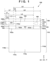
- FIG. 1 is a front view showing the front side of an image forming apparatus 100.
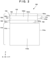
- FIG. 2 is a side view showing the left side of the image forming apparatus 100.
- FIG. 3 is a rear view showing the rear side of the image forming apparatus 100.
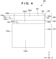
- FIG. 4 is a right side view showing the right side of the image forming apparatus 100.
- FIG. 5 is a schematic cross-sectional view for illustrating the internal structure of an image forming unit 110.
- the X direction represents the width direction of the image forming apparatus 100.
- the Y direction represents the depth direction of the image forming apparatus 100.
- the Z direction represents the height direction of the image forming apparatus 100.
- the image forming apparatus 100 includes the image forming unit 110 and an image reading device 150.
- the image forming unit 110 forms images on sheets S based on image data of a document obtained by the image reading device 150.
- the case of the image forming unit 110 has a front surface 110a, a left side surface 110b, a rear surface 110c ( FIG. 3 ), and a right side surface 110d.
- a left beam 102 and a right beam 103 are provided on the upper side of the image forming unit 110.
- the left beam 102 and the right beam 103 function as a supporting member that supports the image reading device 150.
- the case of the left beam 102 has a front surface 102a, a left side surface 102b, a rear surface 102c ( FIG. 3 ), and a right side surface 102d.
- the case of the right beam 103 has a front surface 103a, a left side surface 103b, a rear surface 103c ( FIG. 3 ), and a right side surface 103d.
- a discharge stacking unit 101 on which sheets S discharged from the image forming unit 110 are stacked is provided between the left beam 102 and the right beam 103. As shown in FIG. 5 , the stacking surface of the discharge stacking unit 101 may have a downward slope surface in a region extending from the front surface 110a of the image forming unit 110 to the rear surface 110c.
- the image reading device 150 includes an image reading unit 151, a cover 152, a platen glass 153, an image sensor 160, and the like.
- the platen glass 153 is disposed on the upper side of the image reading unit 151.
- the cover 152 for exposing or protecting the platen glass 153 is provided above the platen glass 153.
- the image reading unit 151 and the cover 152 are coupled to each other by hinges 154 provided in the vicinity of the rear surface 150c.
- the hinges 154 enable the cover 152 to rotate relative to the image reading unit 151.
- a hinge 155 is provided between the image reading device 150 (image reading unit 151) and the left beam 102.
- the hinge 155 is also provided between the image reading device 150 (image reading unit 151) and the right beam 103.
- the hinges 155 enable the image reading device 150 to rotate relative to the image forming unit 110. An image reading operation will be described in detail later with reference to FIG. 5 .
- the image reading device 150 has a front surface 150a, a left side surface 150b, a rear surface 150c ( FIG. 3 ), and a right side surface 150d.
- An operation unit 170 is provided on the front surface 150a of the image reading unit 151.
- the operation unit 170 has a front surface 170a, a left side surface 170b, and a right side surface 170d. Note that, in a case where the case of operation unit 170 is integrated with the case of the image reading unit 151, the operation unit 170 does not need to have a rear surface.
- a feeding cassette 13 is provided below the image forming unit 110, and can accommodate a large number of sheets S.
- An elevating plate 14 can elevate a large number of sheets S.
- a feeding roller 11 and a separation pad 12 separate a sheet S from a plurality of sheets S taken out from the feeding cassette 13, and feed the sheet S to a conveyance path P1.
- a photosensitive drum 1 is an image carrying member that rotates while carrying an electrostatic latent image or a toner image.
- a charging member 2 charges the surface of the photosensitive drum 1 such that the surface potential of the photosensitive drum 1 is a uniform potential.
- An exposure light source 3 outputs a laser beam 4 modulated based on image data, and scans the laser beam 4 over the photosensitive drum 1. Accordingly, an electrostatic latent image is formed on the surface of the photosensitive drum 1.
- a developing roller 5 develops the electrostatic latent image using toner and forms a toner image.
- a transfer roller 6 faces the photosensitive drum 1, and transfers the toner image from the photosensitive drum 1 onto the sheet S.
- a fixing unit 17 includes a heating roller 15 and a pressing roller 16. The heating roller 15 heats the sheet S and the toner image, and the pressing roller 16 pressurizes the sheet S and the toner image. Accordingly, the toner image is fixed to the sheet S.
- a discharge roller 18 discharges the sheet S to the upper side of the discharge stacking unit 101.
- the image forming unit 110 may employ an image forming method different from the electrophotographic method.
- An inkjet recording method may be employed, for example.
- the image reading device 150 is disposed above the discharge stacking unit 101.
- the image reading device 150 includes the image reading unit 151, the platen glass 153, and the cover 152.
- the image reading unit 151 causes the image sensor 160 to read a document placed on the platen glass 153, generates image data, and outputs the image data to the image forming unit 110. This realizes copy of the document.
- the platen glass 153 is a transparent plate having a light-transmitting property.
- the cover 152 can rotate using the hinges 154 as a rotation shaft, and move between a position at which the platen glass 153 is exposed and a position at which the platen glass 153 is protected.
- the user opens the cover 152, places a document on the platen glass 153, and gives an instruction to read the document through the operation unit 170.
- the image reading unit 151 illuminates the document, and causes the image sensor 160 to read the document while moving the image sensor 160 in the X direction.
- the image reading unit 151 may transmit image data of the document as electronic data to an external computer or store the image data in a removable medium, instead of transmitting the image data to the image forming unit 110.
- the left beam 102 is provided on the upper left side of the image forming unit 110.
- the right beam 103 is provided on the upper right side of the image forming unit 110.
- the image reading device 150 is disposed on the upper side of the left beam 102 and the right beam 103. That is to say, the left beam 102 and the right beam 103 support the image reading device 150 disposed above the image forming unit 110.
- the width of the image reading device 150 is larger than the width of the image forming unit 110. As shown in FIG. 1 , the left side surface 150b of the image reading device 150 protrudes in the leftward direction (X direction) beyond the left side surface 110b of the image forming unit 110.
- L1 denotes the amount of protrusion of the image reading device 150 with respect to the image forming unit 110.
- L2 denotes the distance between the left side surface 110b of the image forming unit 110 and the left side surface 170b of the operation unit 170.
- L3 denotes the distance between the left side surface 170b of the operation unit 170 and the right side surface 102d of the left beam 102.
- L4 denotes the distance between the left side surface 170b of the operation unit 170 and the left side surface 103b of the right beam 103.
- L3 is shorter than L4.
- L5 denotes the distance between the right side surface 170d of the operation unit 170 and the right side surface 102d of the left beam 102.
- L6 denotes the distance between the right side surface 170d of the operation unit 170 and the left side surface 103b of the right beam 103.
- L5 is shorter than L6.
- L7 denotes the distance between the left side surface 150b of the image reading device 150 and the right side surface 102d of the left beam 102.
- L8 denotes the distance between the right side surface 150d of the image reading device 150 and the right side surface 102d of the left beam 102.
- L7 is shorter than L8.
- FIG. 6 is a front view showing a state where the image reading device 150 has moved to an open position relative to the image forming unit 110 using the hinges 155.
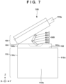
- FIG. 7 is a left side view showing a state where the image reading device 150 has moved to the open position relative to the image forming unit 110 using the hinges 155.
- a bottom surface 170f of the operation unit 170 is visible.
- the holding mechanism 600 may have a structure similar to an open-type link mechanism. Note that it is sufficient that the holding mechanism 600 is a mechanism that can hold and fix the image reading device 150. For this reason, the holding mechanism 600 may be a mechanism different from the open-type link mechanism.
- the holding mechanism 600 may be realized by an oil damper or the like.
- FIG. 8 shows the operation unit 170 of the image forming apparatus 100.
- the operation unit 170 for operating the image forming apparatus 100 may be formed integrally with the image reading unit 151.
- the operation unit 170 includes a display region 811 and an operation region 812.
- the display region 811 includes a liquid crystal display device, an organic EL display device, or the like.
- the operation region 812 includes a hardware switch or a software switch (e.g., a touch sensor).
- the front surface 103a of the right beam 103 is positioned rearward of (on the -Y direction side relative to) the front surface 102a of the left beam 102.
- the distance between the front surface 103a of the right beam 103 and the front surface 102a of the left beam 102 in the Y direction is denoted by d1. This makes it easier for the user to remove the sheets S from the discharge stacking unit 101. In particular, for a right-handed user, the sheets S stacked in the discharge stacking unit 101 may be easily accessed.
- the size of the operation unit 170 can be increased while maintaining the size of the image forming apparatus 100 in the width direction (X direction). As a result, the operability of the operation unit 170 is improved. Furthermore, the visual recognizability of display information on the operation unit 170 is improved. That is to say, it is possible to achieve the visual recognizability of the sheets S in the discharge stacking unit 101, the ease of removing the sheets S, and the visual recognizability and the operability of the operation unit 170.
- FIGS. 10 and 11 show a second embodiment that is a variation of the first embodiment.
- FIG. 10 is a front view showing the front side of the image forming apparatus 100 according to the second embodiment.
- FIG. 11 is a plan view of the image forming apparatus 100 according to the second embodiment.
- the operation unit 170 is expanded compared with the first embodiment.
- constituent elements common to the first embodiment are given the same reference signs, and a description thereof is omitted.
- the left side surface 170b of the operation unit 170 is positioned on the left side relative to the left side surface 110b of the image forming unit 110.
- the right side surface 170d of the operation unit 170 is disposed so as not to extend to the right side beyond a central position of the discharge stacking unit 101 having a width d2.
- the position of the left end of the discharge stacking unit 101 in the X direction coincides with the position of the right side surface 102d of the left beam 102
- the position of the right end of the discharge stacking unit 101 coincides with the position of the left side surface 103b of the right beam 103.
- the distance between the right side surface 102d of the left beam 102 (the left end of the discharge stacking unit 101) and the center of the discharge stacking unit 101 in the width direction of the image forming apparatus 100 is d2/2. That is to say, it is sufficient that the distance L5 between the right side surface 102d of the left beam 102 (the left end of the discharge stacking unit 101) and the right side surface 170d of the operation unit 170 is equal to or shorter than d2/2.
- the second embodiment it is possible to increase at least one of the display area and the operation area of the operation unit 170. Furthermore, the visual recognizability of the sheets S discharged to the upper side of the discharge stacking unit 101 and the ease of removing the sheets S may be lower than those of the first embodiment, but are still improved compared with conventional technologies.
- the display region 811 of the operation unit 170 is expanded, the amount of display information increases.
- the operation region 812 is expanded, the number of operation buttons and the like increase, and the operability is improved.
- FIGS. 12 and 13 show a third embodiment that is a variation of the first and second embodiments.
- FIG. 12 shows the front side of the image forming apparatus 100 according to the third embodiment.
- FIG. 13 is a plan view of the image forming apparatus 100 according to the third embodiment.
- an ADF 1200 is adopted in place of the cover 152.
- ADF is an abbreviation for Auto Document Feeder.
- the image reading device 150 can also support an operation of skimming through a document, as a result of mounting the ADF 1200.
- the image sensor 160 In a fixed reading mode for reading a document placed on the platen glass 153, the image sensor 160 reads the document while moving in the width direction of the image reading device 150 (X direction).
- the image sensor 160 In a skimming mode, the image sensor 160 reads a document that is being conveyed by the ADF 1200 while stopping in the vicinity of the left end of the image reading device 150.
- the image sensor 160 is fixed in the vicinity of the right end of the image reading device 150 in both modes, and a light source that illuminates a document and an optical box that directs the light from the document to the image sensor 160 reciprocates in the X direction.
- the ADF 1200 includes a feeding tray 1201 on which a document is stacked, a feeding unit 1202 for feeding the document, and a discharge tray 1203.
- the image sensor 160 moves to a reading position, and the feeding roller of the feeding unit 1202 starts feeding the document stacked on the feeding tray 1201.
- the document enters the feeding unit 1202 from a feeding port 1204, and is conveyed along a conveyance path P2.
- the image sensor 160 reads the document passing through the reading position, and generates image data.
- the document is then discharged to and stacked on the discharge tray 1203.
- image data is transmitted to the image forming unit 110.
- the image forming unit 110 forms an image of the document on the sheet S, and discharges the sheet S to the discharge stacking unit 101.
- a document insertion/removing direction of the ADF 1200 (the direction in which the user places a document on the feeding tray 1201 and the direction in which the user removes the document from the discharge tray 1203) is parallel to the Y direction.
- the direction in which the user visually recognizes and removes the sheets S on the discharge stacking unit 101 is also generally parallel to the Y direction. This suggests that the user (worker) does not need to make any major change to the sight line.
- the visual recognizability and the operability of the document, and the visual recognizability and the operability of a copied article are improved.
- the operation unit 170 may have a tilt mechanism 1400.
- the tilt mechanism 1400 can be realized by a torque, a hinge, or the like.
- the tilt mechanism 1400 can be realized by a rotation shaft about which the operation unit 170 rotates, and a friction mechanism for holding the operation unit 170 at a fixed position, for example.
- a tilt angle A of the display region 811 can be suitably adjusted using the tilt mechanism.
- the operation region 812 may be realized by a touch sensor. In this case, the operation region 812 may overlap the display region 811. That is to say, the operation unit 170 may be realized as a touch panel.
- the left beam 102 and the right beam 103 are examples of a supporting member that is provided between the image reading device 150 and the image forming unit 110 in the height direction of the image forming apparatus 100, and supports the image reading device 150 disposed above the image forming unit.
- the discharge stacking unit 101 is an example of a stacking unit that is provided between the image reading device 150 and the image forming unit 110 in the height direction of the image forming apparatus 100, and is disposed adjacent to the supporting member, and on which sheets discharged from the image forming unit 110 are stacked.
- a discharge roller 108 is an example of a discharge unit that is provided in the image forming unit 110, and discharges sheets from the image forming unit 110 to the stacking unit.
- the operation unit 170 accepts input for operating at least one of the image forming unit 110 and the image reading device 150, and is supported by the image reading device 150, on the front side of the image forming apparatus 100.
- the operation unit 170 is offset with respect to the stacking unit and the image forming unit 110. As a result, it is possible to achieve all of the visual recognizability of sheets discharged to the stacking unit, the ease of removing the sheets, the visual recognizability and the operability of the operation unit 170.
- the hinges 155 are an example of a hinge mechanism for rotatably supporting the image reading device 150 relative to the image forming unit 110.
- the image reading device 150 By the image reading device 150 being spaced apart from the image forming unit 110, the user may be able to more easily remove sheets from the stacking unit.
- the operation unit 170 is disposed to be offset with respect to the stacking unit and the image forming unit 110. As a result, it is possible to achieve all of the visual recognizability of sheets discharged to the stacking unit, the ease of removing the sheets, the visual recognizability of the operation unit 170, and the operability of the operation unit.
- the distance between the right side surface 170d, which is the second end portion, and the first stacking end is smaller than the distance between the second end portion and the second stacking end, and thus the operation unit is unlikely to hinder the visual recognizability of the stacking unit.
- the position of the first stacking end of the stacking unit is substantially the same as the position of the right side surface 102d of the left beam 102.
- the distance between the right side surface 170d and the first stacking end (e.g., L5) is shorter than the distance between the right side surface 170d and the central position of the stacking unit (e.g., d2/2). Accordingly, the visual recognizability of the stacking unit and the ease of removing sheets may be improved.
- the discharge unit may discharge sheets in a direction from the rear side of the image forming apparatus 100 to the front side. Accordingly, the user (operator) can remove sheets from the front side of the image forming apparatus 100, and the ease of removing sheets is improved.
- the ADF 1200 is an example of a document feeding device that feeds a document to the upper side of a transparent plate one sheet at a time.
- the distance between the feeding port 1204 of the document feeding device and the left side surface 170b of the operation unit 170 may be shorter than the distance between the feeding port 1204 and the right side surface 110d.
- the difference between these two distances is denoted by d1.
- the operation unit is disposed closer to a first supporting portion than to a second supporting portion.
- the first supporting portion needs to support a larger weight.
- the first supporting portion may be larger than the second supporting portion and extend closer to the front side.
- a connector may be provided on the first supporting portion positioned on the front side relative to the second supporting portion. This makes it easy for the user to access the connector.
- the holding mechanism 600 is an example of a holding unit that holds the image reading device 150 at a second position. This may enable the user to easily hold the image reading device 150 and also improve the ease of removing sheets.
- the holding mechanism 600 may include a link mechanism that includes the fixed-end rotation shaft 601 fixed to the image reading device 150, the fixed-end rotation shaft 605 fixed to the supporting member, and a link member connected these shafts (e.g., the upper coupling rod 602, the lower coupling rod 604, and the free-end rotation shaft 603).
- a link mechanism that includes the fixed-end rotation shaft 601 fixed to the image reading device 150, the fixed-end rotation shaft 605 fixed to the supporting member, and a link member connected these shafts (e.g., the upper coupling rod 602, the lower coupling rod 604, and the free-end rotation shaft 603).
- the operation unit 170 may include a tilt mechanism that is tilted between a first state where the operation unit 170 is standing and a second state in which the operation unit 170 is lying. As illustrated in FIG. 14 , by adopting the tilt mechanism, the user can adjust the visual recognizability and the operability of the operation unit.
- the front side of the operation unit 170 may protrude outward beyond the front side of the image reading device 150. This may make it possible to increase the area of the operation unit, and further improve the operability and the visual recognizability of the operation unit.
- the front surface 110a of the image forming unit 110 may protrude outward beyond the front surface 150a of the image reading device 150. This improves the visual recognizability of sheets stacked on the stacking unit and the ease of removing the sheets.
- Embodiment (s) of the present invention can also be realized by a computer of a system or apparatus that reads out and executes computer executable instructions (e.g., one or more programs) recorded on a storage medium (which may also be referred to more fully as a 'non-transitory computer-readable storage medium') to perform the functions of one or more of the above-described embodiment(s) and/or that includes one or more circuits (e.g., application specific integrated circuit (ASIC)) for performing the functions of one or more of the above-described embodiment(s), and by a method performed by the computer of the system or apparatus by, for example, reading out and executing the computer executable instructions from the storage medium to perform the functions of one or more of the above-described embodiment(s) and/or controlling the one or more circuits to perform the functions of one or more of the above-described embodiment(s).
- computer executable instructions e.g., one or more programs
- a storage medium which may also be referred to more fully as
- the computer may comprise one or more processors (e.g., central processing unit (CPU), micro processing unit (MPU)) and may include a network of separate computers or separate processors to read out and execute the computer executable instructions.
- the computer executable instructions may be provided to the computer, for example, from a network or the storage medium.
- the storage medium may include, for example, one or more of a hard disk, a random-access memory (RAM), a read only memory (ROM), a storage of distributed computing systems, an optical disk (such as a compact disc (CD), digital versatile disc (DVD), or Blu-ray Disc (BD) TM ), a flash memory device, a memory card, and the like.
Landscapes
- Engineering & Computer Science (AREA)
- Multimedia (AREA)
- Signal Processing (AREA)
- Physics & Mathematics (AREA)
- General Physics & Mathematics (AREA)
- Microelectronics & Electronic Packaging (AREA)
- Human Computer Interaction (AREA)
- Electrophotography Configuration And Component (AREA)
- Facsimiles In General (AREA)
Abstract
Description
- The present invention relates to an image forming apparatus.
- There are known image forming apparatuses in which an image forming unit forms, on a sheet, an image read by an image reading device, and the sheet is discharged to a stacking unit provided above the image forming unit. According to
Japanese Patent Laid-Open No. 2022-157991 - In conventional image forming apparatuses, an operation unit is disposed above and covers a stacking unit. For this reason, it has not been easy for the user to visually recognize discharged sheets due to the operation unit blocking the view. In particular, small sheets are not visible to the user. There may be cases where the operation unit prohibits the user from removing a sheet. A decrease in the size of the operation unit may make it easy to visually recognize a sheet discharged to the stacking unit. However, in exchange for that, the operability of the operation unit may decrease, and it may be difficult to visually recognize information displayed on the operation unit.
- The present disclosure provides an image forming apparatus as specified in
Claims 1 to 18. - Further features of the present invention will become apparent from the following description of exemplary embodiments (with reference to the attached drawings).
-
-
FIG. 1 is a front view illustrating an image forming apparatus. -
FIG. 2 is a left side view illustrating the image forming apparatus. -
FIG. 3 is a rear view illustrating the image forming apparatus. -
FIG. 4 is a right side view illustrating the image forming apparatus. -
FIG. 5 is a schematic cross-sectional view illustrating the interior of an image forming unit. -
FIG. 6 is a front view illustrating a state where an image reading device is open. -
FIG. 7 is a left side view illustrating the state where the image reading device is open and a holding mechanism. -
FIG. 8 is a diagram illustrating an operation unit. -
FIG. 9 is a perspective view showing the state where the image reading device is open. -
FIG. 10 is a front view illustrating a variation. -
FIG. 11 is a plan view illustrating the variation. -
FIG. 12 is a front view illustrating a variation. -
FIG. 13 is a plan view illustrating the variation. -
FIG. 14 is a perspective view illustrating a variation. - Hereinafter, embodiments will be described in detail with reference to the attached drawings. Note, the following embodiments are not intended to limit the scope of the claimed invention. Multiple features are described in the embodiments, but limitation is not made to an invention that requires all such features, and multiple such features may be combined as appropriate. Furthermore, in the attached drawings, the same reference numerals are given to the same or similar configurations, and redundant description thereof is omitted.
-
FIG. 1 is a front view showing the front side of animage forming apparatus 100.FIG. 2 is a side view showing the left side of theimage forming apparatus 100.FIG. 3 is a rear view showing the rear side of theimage forming apparatus 100.FIG. 4 is a right side view showing the right side of theimage forming apparatus 100.FIG. 5 is a schematic cross-sectional view for illustrating the internal structure of animage forming unit 110. The X direction represents the width direction of theimage forming apparatus 100. The Y direction represents the depth direction of theimage forming apparatus 100. The Z direction represents the height direction of theimage forming apparatus 100. - As shown in
FIGS. 1 to 4 , theimage forming apparatus 100 includes theimage forming unit 110 and animage reading device 150. Theimage forming unit 110 forms images on sheets S based on image data of a document obtained by theimage reading device 150. As shown inFIGS. 1 to 4 , the case of theimage forming unit 110 has afront surface 110a, aleft side surface 110b, arear surface 110c (FIG. 3 ), and aright side surface 110d. Aleft beam 102 and aright beam 103 are provided on the upper side of theimage forming unit 110. Theleft beam 102 and theright beam 103 function as a supporting member that supports theimage reading device 150. The case of theleft beam 102 has afront surface 102a, aleft side surface 102b, arear surface 102c (FIG. 3 ), and aright side surface 102d. The case of theright beam 103 has afront surface 103a, aleft side surface 103b, arear surface 103c (FIG. 3 ), and aright side surface 103d. Adischarge stacking unit 101 on which sheets S discharged from theimage forming unit 110 are stacked is provided between theleft beam 102 and theright beam 103. As shown inFIG. 5 , the stacking surface of thedischarge stacking unit 101 may have a downward slope surface in a region extending from thefront surface 110a of theimage forming unit 110 to therear surface 110c. - The
image reading device 150 includes animage reading unit 151, acover 152, aplaten glass 153, animage sensor 160, and the like. Theplaten glass 153 is disposed on the upper side of theimage reading unit 151. Thecover 152 for exposing or protecting theplaten glass 153 is provided above theplaten glass 153. As shown inFIG. 3 , theimage reading unit 151 and thecover 152 are coupled to each other byhinges 154 provided in the vicinity of therear surface 150c. Thehinges 154 enable thecover 152 to rotate relative to theimage reading unit 151. Note that ahinge 155 is provided between the image reading device 150 (image reading unit 151) and theleft beam 102. Anotherhinge 155 is also provided between the image reading device 150 (image reading unit 151) and theright beam 103. Thehinges 155 enable theimage reading device 150 to rotate relative to theimage forming unit 110. An image reading operation will be described in detail later with reference toFIG. 5 . Theimage reading device 150 has afront surface 150a, aleft side surface 150b, arear surface 150c (FIG. 3 ), and aright side surface 150d. - An
operation unit 170 is provided on thefront surface 150a of theimage reading unit 151. Theoperation unit 170 has afront surface 170a, aleft side surface 170b, and aright side surface 170d. Note that, in a case where the case ofoperation unit 170 is integrated with the case of theimage reading unit 151, theoperation unit 170 does not need to have a rear surface. - According to
FIG. 5 , a feedingcassette 13 is provided below theimage forming unit 110, and can accommodate a large number of sheets S.An elevating plate 14 can elevate a large number of sheets S. A feedingroller 11 and aseparation pad 12 separate a sheet S from a plurality of sheets S taken out from the feedingcassette 13, and feed the sheet S to a conveyance path P1. - A
photosensitive drum 1 is an image carrying member that rotates while carrying an electrostatic latent image or a toner image. A chargingmember 2 charges the surface of thephotosensitive drum 1 such that the surface potential of thephotosensitive drum 1 is a uniform potential. An exposurelight source 3 outputs alaser beam 4 modulated based on image data, and scans thelaser beam 4 over thephotosensitive drum 1. Accordingly, an electrostatic latent image is formed on the surface of thephotosensitive drum 1. - A developing
roller 5 develops the electrostatic latent image using toner and forms a toner image. Atransfer roller 6 faces thephotosensitive drum 1, and transfers the toner image from thephotosensitive drum 1 onto the sheet S. A fixingunit 17 includes aheating roller 15 and a pressing roller 16. Theheating roller 15 heats the sheet S and the toner image, and the pressing roller 16 pressurizes the sheet S and the toner image. Accordingly, the toner image is fixed to the sheet S.A discharge roller 18 discharges the sheet S to the upper side of thedischarge stacking unit 101. - Note that the
image forming unit 110 may employ an image forming method different from the electrophotographic method. An inkjet recording method may be employed, for example. - As shown in
FIG. 1 and the like, theimage reading device 150 is disposed above thedischarge stacking unit 101. Theimage reading device 150 includes theimage reading unit 151, theplaten glass 153, and thecover 152. Theimage reading unit 151 causes theimage sensor 160 to read a document placed on theplaten glass 153, generates image data, and outputs the image data to theimage forming unit 110. This realizes copy of the document. Theplaten glass 153 is a transparent plate having a light-transmitting property. As suggested inFIGS. 2 and4 , thecover 152 can rotate using thehinges 154 as a rotation shaft, and move between a position at which theplaten glass 153 is exposed and a position at which theplaten glass 153 is protected. - The user opens the
cover 152, places a document on theplaten glass 153, and gives an instruction to read the document through theoperation unit 170. In accordance with this, theimage reading unit 151 illuminates the document, and causes theimage sensor 160 to read the document while moving theimage sensor 160 in the X direction. Theimage reading unit 151 may transmit image data of the document as electronic data to an external computer or store the image data in a removable medium, instead of transmitting the image data to theimage forming unit 110. - As shown in
FIGS. 1 to 5 , theleft beam 102 is provided on the upper left side of theimage forming unit 110. Theright beam 103 is provided on the upper right side of theimage forming unit 110. Theimage reading device 150 is disposed on the upper side of theleft beam 102 and theright beam 103. That is to say, theleft beam 102 and theright beam 103 support theimage reading device 150 disposed above theimage forming unit 110. - If the size of the
image forming apparatus 100 is reduced, the width of theimage reading device 150 is larger than the width of theimage forming unit 110. As shown inFIG. 1 , theleft side surface 150b of theimage reading device 150 protrudes in the leftward direction (X direction) beyond theleft side surface 110b of theimage forming unit 110. - As shown in
FIG. 1 , the distance between theleft side surface 110b of theimage forming unit 110 and theleft side surface 150b of theimage reading device 150 in the X direction is L1. Therefore, L1 denotes the amount of protrusion of theimage reading device 150 with respect to theimage forming unit 110. L2 denotes the distance between theleft side surface 110b of theimage forming unit 110 and theleft side surface 170b of theoperation unit 170. L3 denotes the distance between theleft side surface 170b of theoperation unit 170 and theright side surface 102d of theleft beam 102. L4 denotes the distance between theleft side surface 170b of theoperation unit 170 and theleft side surface 103b of theright beam 103. L3 is shorter than L4. L5 denotes the distance between theright side surface 170d of theoperation unit 170 and theright side surface 102d of theleft beam 102. L6 denotes the distance between theright side surface 170d of theoperation unit 170 and theleft side surface 103b of theright beam 103. L5 is shorter than L6. L7 denotes the distance between theleft side surface 150b of theimage reading device 150 and theright side surface 102d of theleft beam 102. L8 denotes the distance between theright side surface 150d of theimage reading device 150 and theright side surface 102d of theleft beam 102. L7 is shorter than L8. -
FIG. 6 is a front view showing a state where theimage reading device 150 has moved to an open position relative to theimage forming unit 110 using thehinges 155.FIG. 7 is a left side view showing a state where theimage reading device 150 has moved to the open position relative to theimage forming unit 110 using thehinges 155. InFIG. 6 , abottom surface 170f of theoperation unit 170 is visible. - A
holding mechanism 600 is a mechanism for holding and fixing theimage reading device 150 at the open position. Theholding mechanism 600 is provided on theleft beam 102. When theimage reading device 150 is moved to a closed position, theholding mechanism 600 is folded and is accommodated in a groove-like housing space 606 provided in theleft beam 102. - The
holding mechanism 600 includes alower coupling rod 604, anupper coupling rod 602, fixed-end rotation shafts end rotation shaft 603. The fixed-end rotation shaft 601 is fixed to the bottom surface side of theimage reading device 150 and passes through theupper coupling rod 602. Accordingly, theupper coupling rod 602 pivots about the fixed-end rotation shaft 601. The lower end of theupper coupling rod 602 and the upper end of thelower coupling rod 604 overlap each other, and the free-end rotation shaft 603 passes therethrough. Theupper coupling rod 602 and thelower coupling rod 604 pivot relative to each other about the free-end rotation shaft 603. The fixed-end rotation shaft 605 passes through the lower end of thelower coupling rod 604. Thelower coupling rod 604 pivots about the fixed-end rotation shaft 605. The fixed-end rotation shaft 605 is fixed to a left wall surface and a right wall surface that define thehousing space 606. - As shown in
FIG. 7 , theholding mechanism 600 may have a structure similar to an open-type link mechanism. Note that it is sufficient that theholding mechanism 600 is a mechanism that can hold and fix theimage reading device 150. For this reason, theholding mechanism 600 may be a mechanism different from the open-type link mechanism. Theholding mechanism 600 may be realized by an oil damper or the like. - When the
image reading device 150 is at the open position, theupper coupling rod 602 and thelower coupling rod 604 are fixed, and theimage reading device 150 is maintained at the open position. At this time, theupper coupling rod 602 and thelower coupling rod 604 may be in a braced state. When theimage reading device 150 is at the closed position, theupper coupling rod 602 and thelower coupling rod 604 fold together, and are stored in thehousing space 606 in theleft beam 102. -
FIG. 8 shows theoperation unit 170 of theimage forming apparatus 100. Theoperation unit 170 for operating theimage forming apparatus 100 may be formed integrally with theimage reading unit 151. Theoperation unit 170 includes adisplay region 811 and anoperation region 812. Thedisplay region 811 includes a liquid crystal display device, an organic EL display device, or the like. Theoperation region 812 includes a hardware switch or a software switch (e.g., a touch sensor). - As shown in
FIG. 1 , theleft side surface 170b of theoperation unit 170 is located about L2 to the left of theleft side surface 110b of theimage forming unit 110. Here, 0 < L2 ≤ L1. -
FIG. 9 is a perspective view of theimage forming apparatus 100 in a state where theimage reading device 150 is open relative to theimage forming unit 110. AUSB connector 901 is provided on thefront surface 102a of theleft beam 102. USB is an abbreviation for Universal Serial Bus. In this example, aremovable memory 902 is connected to theUSB connector 901. Theremovable memory 902 stores, for example, image data of a document obtained by theimage reading device 150 or image data to be printed. Note that, in a state where theimage reading device 150 is in a closed state relative to theimage forming unit 110, theUSB connector 901 is positioned below theoperation unit 170. - The
front surface 103a of theright beam 103 is positioned rearward of (on the -Y direction side relative to) thefront surface 102a of theleft beam 102. The distance between thefront surface 103a of theright beam 103 and thefront surface 102a of theleft beam 102 in the Y direction is denoted by d1. This makes it easier for the user to remove the sheets S from thedischarge stacking unit 101. In particular, for a right-handed user, the sheets S stacked in thedischarge stacking unit 101 may be easily accessed. - As shown in
FIG. 9 , the left stacking end of thedischarge stacking unit 101 may be integral with theright side surface 102d of theleft beam 102. Similarly, the right stacking end of thedischarge stacking unit 101 may be integral with theleft side surface 103b of theright beam 103. That is to say, in the X direction, the position of theright side surface 102d coincides with the position of the left stacking end of thedischarge stacking unit 101. In the X direction, the position of theleft side surface 103b of theright beam 103 coincides with the position of the right stacking end of thedischarge stacking unit 101. - As shown in
FIG. 9 , theoperation unit 170, theholding mechanism 600, and theUSB connector 901 are disposed on the left side of theimage forming apparatus 100 in a concentrated manner. Furthermore, theright beam 103 is positioned rearward of theleft beam 102. This improves the visual recognizability of the sheets S discharged and stacked on thedischarge stacking unit 101. Furthermore, the ease of removing the sheets S from thedischarge stacking unit 101 improves. - The size of the
operation unit 170 can be increased while maintaining the size of theimage forming apparatus 100 in the width direction (X direction). As a result, the operability of theoperation unit 170 is improved. Furthermore, the visual recognizability of display information on theoperation unit 170 is improved. That is to say, it is possible to achieve the visual recognizability of the sheets S in thedischarge stacking unit 101, the ease of removing the sheets S, and the visual recognizability and the operability of theoperation unit 170. - In the first embodiment, the
image reading device 150 protrudes to the left side beyond theimage forming unit 110. However, this is merely exemplary. Theimage reading device 150 may protrude to the right side beyond theimage forming unit 110. -
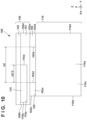
FIGS. 10 and11 show a second embodiment that is a variation of the first embodiment. In particular,FIG. 10 is a front view showing the front side of theimage forming apparatus 100 according to the second embodiment.FIG. 11 is a plan view of theimage forming apparatus 100 according to the second embodiment. In particular, in the second embodiment, theoperation unit 170 is expanded compared with the first embodiment. In the second embodiment, constituent elements common to the first embodiment are given the same reference signs, and a description thereof is omitted. - The
left side surface 170b of theoperation unit 170 is positioned on the left side relative to theleft side surface 110b of theimage forming unit 110. In the width direction of theimage forming apparatus 100, theright side surface 170d of theoperation unit 170 is disposed so as not to extend to the right side beyond a central position of thedischarge stacking unit 101 having a width d2. InFIG. 10 , as an example, the position of the left end of thedischarge stacking unit 101 in the X direction coincides with the position of theright side surface 102d of theleft beam 102, and the position of the right end of thedischarge stacking unit 101 coincides with the position of theleft side surface 103b of theright beam 103. Thus, the distance between theright side surface 102d of the left beam 102 (the left end of the discharge stacking unit 101) and the center of thedischarge stacking unit 101 in the width direction of theimage forming apparatus 100 is d2/2. That is to say, it is sufficient that the distance L5 between theright side surface 102d of the left beam 102 (the left end of the discharge stacking unit 101) and theright side surface 170d of theoperation unit 170 is equal to or shorter than d2/2. - In this manner, according to the second embodiment, it is possible to increase at least one of the display area and the operation area of the
operation unit 170. Furthermore, the visual recognizability of the sheets S discharged to the upper side of thedischarge stacking unit 101 and the ease of removing the sheets S may be lower than those of the first embodiment, but are still improved compared with conventional technologies. When thedisplay region 811 of theoperation unit 170 is expanded, the amount of display information increases. When theoperation region 812 is expanded, the number of operation buttons and the like increase, and the operability is improved. -
FIGS. 12 and13 show a third embodiment that is a variation of the first and second embodiments. In particular,FIG. 12 shows the front side of theimage forming apparatus 100 according to the third embodiment.FIG. 13 is a plan view of theimage forming apparatus 100 according to the third embodiment. In the third embodiment, anADF 1200 is adopted in place of thecover 152. ADF is an abbreviation for Auto Document Feeder. - The
image reading device 150 can also support an operation of skimming through a document, as a result of mounting theADF 1200. In a fixed reading mode for reading a document placed on theplaten glass 153, theimage sensor 160 reads the document while moving in the width direction of the image reading device 150 (X direction). On the other hand, in a skimming mode, theimage sensor 160 reads a document that is being conveyed by theADF 1200 while stopping in the vicinity of the left end of theimage reading device 150. Note that a configuration may be adopted in which theimage sensor 160 is fixed in the vicinity of the right end of theimage reading device 150 in both modes, and a light source that illuminates a document and an optical box that directs the light from the document to theimage sensor 160 reciprocates in the X direction. - The
ADF 1200 includes afeeding tray 1201 on which a document is stacked, afeeding unit 1202 for feeding the document, and adischarge tray 1203. When a read instruction is input through theoperation unit 170, theimage sensor 160 moves to a reading position, and the feeding roller of thefeeding unit 1202 starts feeding the document stacked on thefeeding tray 1201. The document enters thefeeding unit 1202 from a feedingport 1204, and is conveyed along a conveyance path P2. Theimage sensor 160 reads the document passing through the reading position, and generates image data. The document is then discharged to and stacked on thedischarge tray 1203. - If an instruction input through the
operation unit 170 is a "copy" instruction, image data is transmitted to theimage forming unit 110. Theimage forming unit 110 forms an image of the document on the sheet S, and discharges the sheet S to thedischarge stacking unit 101. - The user faces the front side of the
image forming apparatus 100, and performs operations on theoperation unit 170. For this reason, a document insertion/removing direction of the ADF 1200 (the direction in which the user places a document on thefeeding tray 1201 and the direction in which the user removes the document from the discharge tray 1203) is parallel to the Y direction. The direction in which the user visually recognizes and removes the sheets S on thedischarge stacking unit 101 is also generally parallel to the Y direction. This suggests that the user (worker) does not need to make any major change to the sight line. Thus, the visual recognizability and the operability of the document, and the visual recognizability and the operability of a copied article are improved. - As shown in
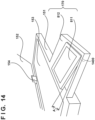
FIG. 14 , theoperation unit 170 may have atilt mechanism 1400. Thetilt mechanism 1400 can be realized by a torque, a hinge, or the like. Thetilt mechanism 1400 can be realized by a rotation shaft about which theoperation unit 170 rotates, and a friction mechanism for holding theoperation unit 170 at a fixed position, for example. InFIG. 14 , a tilt angle A of thedisplay region 811 can be suitably adjusted using the tilt mechanism. Theoperation region 812 may be realized by a touch sensor. In this case, theoperation region 812 may overlap thedisplay region 811. That is to say, theoperation unit 170 may be realized as a touch panel. - The
left beam 102 and theright beam 103 are examples of a supporting member that is provided between theimage reading device 150 and theimage forming unit 110 in the height direction of theimage forming apparatus 100, and supports theimage reading device 150 disposed above the image forming unit. - The
discharge stacking unit 101 is an example of a stacking unit that is provided between theimage reading device 150 and theimage forming unit 110 in the height direction of theimage forming apparatus 100, and is disposed adjacent to the supporting member, and on which sheets discharged from theimage forming unit 110 are stacked. A discharge roller 108 is an example of a discharge unit that is provided in theimage forming unit 110, and discharges sheets from theimage forming unit 110 to the stacking unit. Theoperation unit 170 accepts input for operating at least one of theimage forming unit 110 and theimage reading device 150, and is supported by theimage reading device 150, on the front side of theimage forming apparatus 100. - In this manner, the
operation unit 170 is offset with respect to the stacking unit and theimage forming unit 110. As a result, it is possible to achieve all of the visual recognizability of sheets discharged to the stacking unit, the ease of removing the sheets, the visual recognizability and the operability of theoperation unit 170. - The hinges 155 are an example of a hinge mechanism for rotatably supporting the
image reading device 150 relative to theimage forming unit 110. By theimage reading device 150 being spaced apart from theimage forming unit 110, the user may be able to more easily remove sheets from the stacking unit. - The
operation unit 170 is disposed to be offset with respect to the stacking unit and theimage forming unit 110. As a result, it is possible to achieve all of the visual recognizability of sheets discharged to the stacking unit, the ease of removing the sheets, the visual recognizability of theoperation unit 170, and the operability of the operation unit. In particular, in the width direction of theimage forming apparatus 100, the distance between theright side surface 170d, which is the second end portion, and the first stacking end is smaller than the distance between the second end portion and the second stacking end, and thus the operation unit is unlikely to hinder the visual recognizability of the stacking unit. The position of the first stacking end of the stacking unit is substantially the same as the position of theright side surface 102d of theleft beam 102. - As shown in
FIGS. 10 and11 , theright side surface 170d may be positioned between the first stacking end and theleft side surface 170b, which is a first end portion, in the width direction of theimage forming apparatus 100. Accordingly, it is possible to increase the area of theoperation unit 170. Accordingly, the visual recognizability and the operability of theoperation unit 170 may be improved. - As shown in
FIGS. 10 and11 , in the width direction of theimage forming apparatus 100, theright side surface 170d may be positioned between the first stacking end and the second stacking end. Accordingly, it is possible to increase the area of theoperation unit 170. Accordingly, the visual recognizability and the operability of theoperation unit 170 may be improved. - As shown in
FIGS. 1 and10 , the distance between theright side surface 170d and the first stacking end (e.g., L5) is shorter than the distance between theright side surface 170d and the central position of the stacking unit (e.g., d2/2). Accordingly, the visual recognizability of the stacking unit and the ease of removing sheets may be improved. - As shown in
FIG. 5 , the discharge unit may discharge sheets in a direction from the rear side of theimage forming apparatus 100 to the front side. Accordingly, the user (operator) can remove sheets from the front side of theimage forming apparatus 100, and the ease of removing sheets is improved. - The
image reading device 150 may include a first side surface (e.g., theleft side surface 150b) and a second side surface (e.g., theright side surface 150d). As shown inFIGS. 1 and9 to 12 , the distance between theleft side surface 150b and the first stacking end (e.g., L7) may be shorter than the distance between theright side surface 150d and the first stacking end (e.g., L8). It suffices for theleft side surface 150b to be positioned outside theimage forming unit 110. Accordingly, theimage reading device 150 can read a fixed size document, and the size of theimage forming unit 110 can be reduced. - The
ADF 1200 is an example of a document feeding device that feeds a document to the upper side of a transparent plate one sheet at a time. The distance between the feedingport 1204 of the document feeding device and theleft side surface 170b of theoperation unit 170 may be shorter than the distance between the feedingport 1204 and theright side surface 110d. In this manner, also in theimage forming apparatus 100 that adopts a document feeding device, the visual recognizability of sheets in the stacking unit and the ease of removing the sheets are improved. - The
operation unit 170 may be integrated with the case of theimage reading device 150. This may improve the efficiency of a manufacturing process and an assembly process of the operation unit. - The supporting member may include the
left beam 102 and theright beam 103 that support theimage reading device 150. By adopting the supporting member in this manner, a space can be provided between theimage forming unit 110 and theimage reading device 150, and the stacking unit can be provided in the space. In addition, a space is ensured above the stacking unit by the supporting member, and thus the visual recognizability of the sheets and the ease of removing the sheets may be further improved. - As shown in
FIG. 9 , the difference between these two distances is denoted by d1. In addition, the operation unit is disposed closer to a first supporting portion than to a second supporting portion. For this reason, the first supporting portion needs to support a larger weight. Thus, the first supporting portion may be larger than the second supporting portion and extend closer to the front side. On the other hand, by receding the second supporting portion relative to the first supporting portion, the user can easily remove the sheets from the stacking unit. - A connector may be provided on the first supporting portion positioned on the front side relative to the second supporting portion. This makes it easy for the user to access the connector.
- The
holding mechanism 600 is an example of a holding unit that holds theimage reading device 150 at a second position. This may enable the user to easily hold theimage reading device 150 and also improve the ease of removing sheets. - The
holding mechanism 600 may include a link mechanism that includes the fixed-end rotation shaft 601 fixed to theimage reading device 150, the fixed-end rotation shaft 605 fixed to the supporting member, and a link member connected these shafts (e.g., theupper coupling rod 602, thelower coupling rod 604, and the free-end rotation shaft 603). By adopting the link mechanism, the size of the holding unit may be reduced. - The
operation unit 170 may include a tilt mechanism that is tilted between a first state where theoperation unit 170 is standing and a second state in which theoperation unit 170 is lying. As illustrated inFIG. 14 , by adopting the tilt mechanism, the user can adjust the visual recognizability and the operability of the operation unit. - As shown in
FIGS. 2 ,4 to 7 ,9 ,11 ,13 , and14 , the front side of theoperation unit 170 may protrude outward beyond the front side of theimage reading device 150. This may make it possible to increase the area of the operation unit, and further improve the operability and the visual recognizability of the operation unit. - As shown in
FIG. 9 , thefront surface 110a of theimage forming unit 110 may protrude outward beyond thefront surface 150a of theimage reading device 150. This improves the visual recognizability of sheets stacked on the stacking unit and the ease of removing the sheets. - Embodiment (s) of the present invention can also be realized by a computer of a system or apparatus that reads out and executes computer executable instructions (e.g., one or more programs) recorded on a storage medium (which may also be referred to more fully as a 'non-transitory computer-readable storage medium') to perform the functions of one or more of the above-described embodiment(s) and/or that includes one or more circuits (e.g., application specific integrated circuit (ASIC)) for performing the functions of one or more of the above-described embodiment(s), and by a method performed by the computer of the system or apparatus by, for example, reading out and executing the computer executable instructions from the storage medium to perform the functions of one or more of the above-described embodiment(s) and/or controlling the one or more circuits to perform the functions of one or more of the above-described embodiment(s). The computer may comprise one or more processors (e.g., central processing unit (CPU), micro processing unit (MPU)) and may include a network of separate computers or separate processors to read out and execute the computer executable instructions. The computer executable instructions may be provided to the computer, for example, from a network or the storage medium. The storage medium may include, for example, one or more of a hard disk, a random-access memory (RAM), a read only memory (ROM), a storage of distributed computing systems, an optical disk (such as a compact disc (CD), digital versatile disc (DVD), or Blu-ray Disc (BD)™), a flash memory device, a memory card, and the like.
- While the present invention has been described with reference to exemplary embodiments, it is to be understood that the invention is not limited to the disclosed exemplary embodiments. The scope of the following claims is to be accorded the broadest interpretation so as to encompass all such modifications and equivalent structures and functions.
Claims (18)
- An image forming apparatus (100) characterized by comprising:image reading means (150) for reading a document;image forming means (110), provided below the image reading means, for forming an image on a sheet;supporting means (102, 103), provided between the image reading means and the image forming means in a height direction of the image forming apparatus, for supporting the image reading means disposed above the image forming means;stacking means (101) provided between the image reading means and the image forming means in the height direction of the image forming apparatus, and disposed adjacent to the supporting means, the sheet is discharged from the image forming means to the stacking means;discharge means (18), provided in the image forming means, for discharging the sheet from the image forming means to the stacking means; andoperation means (170) for accepting input for operating at least one of the image forming means and the image reading means, and supported by the image reading means, on a front side of the image forming apparatus,wherein the supporting means supports the image reading means such that the image reading means is movable between a first position at which a front side of the image reading means is close to the image forming means and a second position at which the front side of the image reading means is spaced apart from the image forming means,a first end portion (170b) of the operation means protrudes outward of the image forming means from one side surface of the image forming means, in a width direction of the image forming apparatus, anda second end portion (170d) of the operation means that opposes the first end portion is positioned on an inner side of the image forming means relative to the one side surface of the image forming means, in the width direction of the image forming apparatus.
- The image forming apparatus according to claim 1, wherein
the supporting means includes hinge means (155) for rotatably supporting the image reading means relative to the image forming means, and the image reading means is supported by the hinge means such that the image reading means is movable between the first position and the second position. - The image forming apparatus according to claim 1 or 2, whereinthe stacking means includes a first stacking end and a second stacking end in the width direction of the image forming apparatus, and a distance between the first stacking end and the first end portion is smaller than a distance between the second stacking end and the first end portion, anda distance between the second end portion and the first stacking end is shorter than a distance between the second end portion and the second stacking end, in the width direction of the image forming apparatus.
- The image forming apparatus according to claim 3, wherein
the second end portion is positioned between the first stacking end and the first end portion in the width direction of the image forming apparatus. - The image forming apparatus according to claim 3, wherein
the second end portion is positioned between the first stacking end and the second stacking end in the width direction of the image forming apparatus. - The image forming apparatus according to claim 3, wherein
the distance between the second end portion and the first stacking end is shorter than a distance between the second end portion and a central position of the stacking means, in the width direction of the image forming apparatus. - The image forming apparatus according to any one of claims 1 to 6, wherein
the discharge means discharges the sheet in a direction from a rear side of the image forming apparatus to the front side. - The image forming apparatus according to any one of claims 2-6, whereinthe image reading means includes a first side surface and a second side surface in the width direction of the image forming apparatus,a distance between the first side surface and the first stacking end is shorter than a distance between the second side surface and the first stacking end, andthe first side surface of the image reading means is positioned outside the image forming means relative to the one side surface of the image forming means, in the width direction of the image forming apparatus.
- The image forming apparatus according to any one of claims 1 to 8, whereinthe image reading means includes:transparent means (153) for supporting the document, and having a light-transmitting property,image sensing means (160) for reading the document supported by the transparent means, anddocument feeding means (1200) for feeding the document to an upper side of the transparent plate one sheet at a time,wherein, in the width direction of the image forming apparatus, a distance between a feeding port of the document feeding means and the first end portion of the operation means is shorter than a distance between the feeding port of the document feeding means and the other side surface opposing the one side surface of the image forming means.
- The image forming apparatus according to any one of claims 1 to 9, wherein
the operation means is integrated with a case of the image reading means. - The image forming apparatus according to any one of claims 1 to 10, whereinthe supporting means includes first and second supporting portions that support the image reading means,a distance between the first supporting portion and the operation means is shorter than a distance between the second supporting portion and the operation means, in the width direction of the image forming apparatus, andthe stacking means is disposed between the first supporting portion and the second supporting portion.
- The image forming apparatus according to claim 11, wherein
in a depth direction of the image forming apparatus, a distance between the first supporting portion and the front side of the image reading means is shorter than a distance between the second supporting portion and the front side of the image reading means. - The image forming apparatus according to claim 12, further comprising
connector means (901) provided on a front side of the first supporting portion, and to which a removable storage means is connected. - The image forming apparatus according to claim 1, further comprising
holding means (600) for holding the image reading means at the second position. - The image forming apparatus according to claim 14, wherein
the holding means includes link means that includes a first fixed end fixed to the image reading means, a second fixed end fixed to the supporting means, and a link member connected to the first fixed end and the second fixed end. - The image forming apparatus according to any one of claims 1 to 15, wherein
the operation means includes tilt means that is tilted between a first state where the operation means is standing and a second state where the operation means is lying. - The image forming apparatus according to claim 1, wherein
a front side of the operation means protrudes outward beyond the front side of the image reading means, in a depth direction of the image forming apparatus. - The image forming apparatus according to claim 17, wherein
a front side of the image forming means protrudes outward beyond the front side of the image reading means, in the depth direction of the image forming apparatus.
Applications Claiming Priority (1)
| Application Number | Priority Date | Filing Date | Title |
|---|---|---|---|
| JP2023193850A JP2025080593A (en) | 2023-11-14 | 2023-11-14 | Image forming device |
Publications (1)
| Publication Number | Publication Date |
|---|---|
| EP4557009A1 true EP4557009A1 (en) | 2025-05-21 |
Family
ID=93521550
Family Applications (1)
| Application Number | Title | Priority Date | Filing Date |
|---|---|---|---|
| EP24212570.6A Pending EP4557009A1 (en) | 2023-11-14 | 2024-11-13 | Image forming apparatus |
Country Status (4)
| Country | Link |
|---|---|
| US (1) | US20250159086A1 (en) |
| EP (1) | EP4557009A1 (en) |
| JP (1) | JP2025080593A (en) |
| CN (1) | CN120017757A (en) |
Citations (5)
| Publication number | Priority date | Publication date | Assignee | Title |
|---|---|---|---|---|
| JP2008065353A (en) * | 2007-11-12 | 2008-03-21 | Nisca Corp | Image forming apparatus |
| US20100091315A1 (en) * | 2008-10-10 | 2010-04-15 | Ricoh Company, Ltd. | Image forming apparatus |
| US20180077307A1 (en) * | 2016-09-09 | 2018-03-15 | Canon Kabushiki Kaisha | Image forming apparatus |
| US20200285188A1 (en) * | 2019-03-04 | 2020-09-10 | Brother Kogyo Kabushiki Kaisha | Image forming apparatus |
| JP2022157991A (en) | 2021-04-01 | 2022-10-14 | ブラザー工業株式会社 | Multi-functional printer |
Family Cites Families (4)
| Publication number | Priority date | Publication date | Assignee | Title |
|---|---|---|---|---|
| JP4389177B2 (en) * | 2006-10-26 | 2009-12-24 | ブラザー工業株式会社 | Image forming apparatus |
| JP5674108B2 (en) * | 2010-10-25 | 2015-02-25 | 富士ゼロックス株式会社 | Image forming apparatus and opening / closing apparatus |
| JP6674130B2 (en) * | 2016-01-05 | 2020-04-01 | セイコーエプソン株式会社 | Recording device |
| JP2020138475A (en) * | 2019-02-28 | 2020-09-03 | ブラザー工業株式会社 | Image forming device |
-
2023
- 2023-11-14 JP JP2023193850A patent/JP2025080593A/en active Pending
-
2024
- 2024-11-11 CN CN202411596681.2A patent/CN120017757A/en active Pending
- 2024-11-12 US US18/944,955 patent/US20250159086A1/en active Pending
- 2024-11-13 EP EP24212570.6A patent/EP4557009A1/en active Pending
Patent Citations (5)
| Publication number | Priority date | Publication date | Assignee | Title |
|---|---|---|---|---|
| JP2008065353A (en) * | 2007-11-12 | 2008-03-21 | Nisca Corp | Image forming apparatus |
| US20100091315A1 (en) * | 2008-10-10 | 2010-04-15 | Ricoh Company, Ltd. | Image forming apparatus |
| US20180077307A1 (en) * | 2016-09-09 | 2018-03-15 | Canon Kabushiki Kaisha | Image forming apparatus |
| US20200285188A1 (en) * | 2019-03-04 | 2020-09-10 | Brother Kogyo Kabushiki Kaisha | Image forming apparatus |
| JP2022157991A (en) | 2021-04-01 | 2022-10-14 | ブラザー工業株式会社 | Multi-functional printer |
Also Published As
| Publication number | Publication date |
|---|---|
| JP2025080593A (en) | 2025-05-26 |
| CN120017757A (en) | 2025-05-16 |
| US20250159086A1 (en) | 2025-05-15 |
Similar Documents
| Publication | Publication Date | Title |
|---|---|---|
| US7957689B2 (en) | Image forming apparatus | |
| US11987471B2 (en) | Image forming apparatus | |
| US11609529B2 (en) | Image forming apparatus with draw-out unit having electrical contact | |
| CN100399209C (en) | Opening/closing mechanism and image forming apparatus using same | |
| US20090245906A1 (en) | Image forming device and image forming apparatus having the same | |
| US6665047B1 (en) | Image forming apparatus | |
| US20250159086A1 (en) | Arrangement of operation unit in image forming apparatus | |
| JP7175671B2 (en) | image forming device | |
| US7463848B2 (en) | Image forming apparatus having a state in which a conveying roller is pressed toward a recording medium | |
| US12459762B2 (en) | Sheet feeding device, image reading device and image forming apparatus | |
| JP7130435B2 (en) | image forming device | |
| US20060140670A1 (en) | Image forming apparatus | |
| JP2006117382A (en) | Automatic document feeder, reading unit including the automatic document feeder, and image forming apparatus | |
| JP2001042588A (en) | Image forming device | |
| JP2004279692A (en) | Image forming device | |
| JP2007286395A (en) | Image forming apparatus and multifunction machine | |
| US7688484B2 (en) | Image-forming device having both an image-reading unit and an image-forming unit being made compact | |
| JP7158951B2 (en) | image forming device | |
| JP2023080719A (en) | image forming device | |
| JP6674148B2 (en) | Image forming apparatus equipped with IC card reader | |
| JP4238863B2 (en) | Image reading apparatus and multi-function machine provided with image reading apparatus | |
| JP2005227634A (en) | Image formation system | |
| EP3330806B1 (en) | Image-forming device | |
| JP2020050467A (en) | Medium storage device and image forming device | |
| JP2023082376A (en) | image forming device |
Legal Events
| Date | Code | Title | Description |
|---|---|---|---|
| PUAI | Public reference made under article 153(3) epc to a published international application that has entered the european phase |
Free format text: ORIGINAL CODE: 0009012 |
|
| STAA | Information on the status of an ep patent application or granted ep patent |
Free format text: STATUS: THE APPLICATION HAS BEEN PUBLISHED |
|
| AK | Designated contracting states |
Kind code of ref document: A1 Designated state(s): AL AT BE BG CH CY CZ DE DK EE ES FI FR GB GR HR HU IE IS IT LI LT LU LV MC ME MK MT NL NO PL PT RO RS SE SI SK SM TR |
|
| STAA | Information on the status of an ep patent application or granted ep patent |
Free format text: STATUS: REQUEST FOR EXAMINATION WAS MADE |
|
| 17P | Request for examination filed |
Effective date: 20251121 |
|
| GRAP | Despatch of communication of intention to grant a patent |
Free format text: ORIGINAL CODE: EPIDOSNIGR1 |
|
| STAA | Information on the status of an ep patent application or granted ep patent |
Free format text: STATUS: GRANT OF PATENT IS INTENDED |
|
| INTG | Intention to grant announced |
Effective date: 20260211 |