EP4556914A1 - Isolation resistance evaluation system for a high voltage battery, in particular for an electric vehicle - Google Patents
Isolation resistance evaluation system for a high voltage battery, in particular for an electric vehicle Download PDFInfo
- Publication number
- EP4556914A1 EP4556914A1 EP24212623.3A EP24212623A EP4556914A1 EP 4556914 A1 EP4556914 A1 EP 4556914A1 EP 24212623 A EP24212623 A EP 24212623A EP 4556914 A1 EP4556914 A1 EP 4556914A1
- Authority
- EP
- European Patent Office
- Prior art keywords
- isolation
- terminal
- battery pack
- circuit
- positive
- Prior art date
- Legal status (The legal status is an assumption and is not a legal conclusion. Google has not performed a legal analysis and makes no representation as to the accuracy of the status listed.)
- Pending
Links
Images
Classifications
-
- G—PHYSICS
- G01—MEASURING; TESTING
- G01R—MEASURING ELECTRIC VARIABLES; MEASURING MAGNETIC VARIABLES
- G01R27/00—Arrangements for measuring resistance, reactance, impedance, or electric characteristics derived therefrom
- G01R27/02—Measuring real or complex resistance, reactance, impedance, or other two-pole characteristics derived therefrom, e.g. time constant
- G01R27/025—Measuring very high resistances, e.g. isolation resistances, i.e. megohm-meters
-
- B—PERFORMING OPERATIONS; TRANSPORTING
- B60—VEHICLES IN GENERAL
- B60L—PROPULSION OF ELECTRICALLY-PROPELLED VEHICLES; SUPPLYING ELECTRIC POWER FOR AUXILIARY EQUIPMENT OF ELECTRICALLY-PROPELLED VEHICLES; ELECTRODYNAMIC BRAKE SYSTEMS FOR VEHICLES IN GENERAL; MAGNETIC SUSPENSION OR LEVITATION FOR VEHICLES; MONITORING OPERATING VARIABLES OF ELECTRICALLY-PROPELLED VEHICLES; ELECTRIC SAFETY DEVICES FOR ELECTRICALLY-PROPELLED VEHICLES
- B60L3/00—Electric devices on electrically-propelled vehicles for safety purposes; Monitoring operating variables, e.g. speed, deceleration or energy consumption
- B60L3/0023—Detecting, eliminating, remedying or compensating for drive train abnormalities, e.g. failures within the drive train
- B60L3/0046—Detecting, eliminating, remedying or compensating for drive train abnormalities, e.g. failures within the drive train relating to electric energy storage systems, e.g. batteries or capacitors
-
- B—PERFORMING OPERATIONS; TRANSPORTING
- B60—VEHICLES IN GENERAL
- B60L—PROPULSION OF ELECTRICALLY-PROPELLED VEHICLES; SUPPLYING ELECTRIC POWER FOR AUXILIARY EQUIPMENT OF ELECTRICALLY-PROPELLED VEHICLES; ELECTRODYNAMIC BRAKE SYSTEMS FOR VEHICLES IN GENERAL; MAGNETIC SUSPENSION OR LEVITATION FOR VEHICLES; MONITORING OPERATING VARIABLES OF ELECTRICALLY-PROPELLED VEHICLES; ELECTRIC SAFETY DEVICES FOR ELECTRICALLY-PROPELLED VEHICLES
- B60L3/00—Electric devices on electrically-propelled vehicles for safety purposes; Monitoring operating variables, e.g. speed, deceleration or energy consumption
- B60L3/0023—Detecting, eliminating, remedying or compensating for drive train abnormalities, e.g. failures within the drive train
- B60L3/0069—Detecting, eliminating, remedying or compensating for drive train abnormalities, e.g. failures within the drive train relating to the isolation, e.g. ground fault or leak current
-
- G—PHYSICS
- G01—MEASURING; TESTING
- G01R—MEASURING ELECTRIC VARIABLES; MEASURING MAGNETIC VARIABLES
- G01R31/00—Arrangements for testing electric properties; Arrangements for locating electric faults; Arrangements for electrical testing characterised by what is being tested not provided for elsewhere
- G01R31/36—Arrangements for testing, measuring or monitoring the electrical condition of accumulators or electric batteries, e.g. capacity or state of charge [SoC]
- G01R31/396—Acquisition or processing of data for testing or for monitoring individual cells or groups of cells within a battery
Definitions
- the present solution relates to an isolation resistance evaluation system for a high-voltage battery (HVB), in particular for an electrically driven, hybrid or fully electric vehicle, so called BEV (Battery Electric Vehicle).
- HVB high-voltage battery
- BEV Battery Electric Vehicle
- BMS Battery Management System
- GFD Ground Fault Detection
- electric or hybrid motor vehicles are provided with an electric or hybrid drive assembly, which is designed to drive at least one wheel resting on the ground; a high-voltage, rechargeable battery pack, which is designed to accumulate a given amount of electrical energy to supply the electric or hybrid drive assembly; and an electronically controlled inverter, which is coupled between the battery pack and the drive assembly and is designed to transform, based on commands given by the driver of the vehicle, the direct current electrical energy coming from the battery pack into alternating current for the drive assembly.
- the battery pack is internally provided with a management module, so-called BMS module, which interacts with the vehicle electronics and is designed to manage the operation and monitor the operating state of the battery pack, for example so as to avoid operation beyond safe conditions.
- BMS module a management module, so-called BMS module, which interacts with the vehicle electronics and is designed to manage the operation and monitor the operating state of the battery pack, for example so as to avoid operation beyond safe conditions.
- the BMS module is designed to control and manage the group of electrochemical cells of the battery pack, monitoring their charge status, temperature, voltage and/or other parameters, in order, for example, to balance the charge status in case of an unbalance between the various electrochemical cells.
- the battery packs of current motor vehicles may even reach nominal voltages of 800 V (generally operating at high voltages, ranging between 400 and 800 V), it is important to be able to detect any ground faults of the battery pack that may compromise the electrical isolation and be hazardous for people and/or the vehicle's low-voltage circuits that share the same ground connection.
- faults may, for example, be due to ageing of the electrical components, various kinds of stress (mechanical, electrical, thermal, or, in general, environmental) or to accidents to which the battery pack may be subjected, such as, for example, the puncturing of a corresponding sealed container in which the electrolytic cells are housed.
- stress mechanical, electrical, thermal, or, in general, environmental
- accidents to which the battery pack may be subjected such as, for example, the puncturing of a corresponding sealed container in which the electrolytic cells are housed.
- the battery packs are equipped with ground fault detection circuits that are able to assess (potentially by means of suitable estimation) the electrical resistance between the positive pole of the battery pack and ground and/or between the negative pole of the same battery pack and ground, in particular operating conditions of the battery pack specified by the current regulations.
- ground fault detection circuits may, advantageously, be included in the BMS module of the high-voltage battery.
- the BMS module thus also has the function of monitoring the above-mentioned isolation resistance of the battery pack, being, for example, configured to interrupt, by means of suitable circuit interruption elements, the supply of loads by the same battery pack if there is a change in the isolation resistance that potentially is indicative of a ground fault.
- known solutions do not enable to locate possible isolation losses inside the battery pack, being, at most, only able to determine whether the isolation inside the battery pack has deteriorated and, if so, to signal the need to replace the whole battery pack.
- the aim of the present invention is, in general, to overcome the limitations associated with the current solutions and, in particular, to provide a solution for evaluating the isolation resistance of a high-voltage battery, in particular for an electric motor vehicle, which is able to estimate the isolation resistance and, in addition, locate a position of the electrolytic cell inside the battery pack where the electric isolation is damaged or, in any case, compromised.
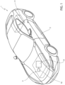
- reference 1 denotes, as a whole, a vehicle, in particular an electric or hybrid motor vehicle that has a body 2 resting on the ground by means of wheels 3 and comprising: an electric or hybrid drive assembly 4, including at least one synchronous or asynchronous electric motor, designed to drive in rotation at least one of the wheels 3; and a rechargeable, high-voltage battery (HVB) 5 that is able to accumulate a given quantity of electrical energy to supply the above-mentioned drive assembly 4.
- HVB high-voltage battery
- the drive assembly 4 and the high-voltage battery 5 are housed inside the body 2, in the example illustrated the electric or hybrid drive assembly 4 being positioned in the rear part and the high-voltage battery 5 in the front part of the body 2.
- an electrical unit in particular including an electronically controlled inverter, is coupled between the high-voltage battery 5 and the drive assembly 4 to transform, based on commands given by the driver of the vehicle, the direct current electrical energy coming from the high-voltage battery 5 into alternating current electrical energy for the drive assembly 4.
- the high-voltage battery 5 has, for example, a nominal capacity greater than or equal to 50 kWh and a nominal voltage ranging between 400 V and 800 Volt, in particular equal to 800 V.
- the high-voltage battery 5 internally comprises a battery pack 8 and a BMS module 10, operationally coupled to the battery pack 8, to manage and supervise its operation.
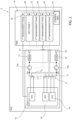
- Figure 2 schematically shows, in a more detailed manner, a possible implementation of the above-mentioned high-voltage battery 5.
- the battery pack 8 consists of a given number of modules or electrochemical cells 12, connected in series between a positive terminal HV + and a negative terminal HV - , between which a battery voltage V HV is provided, which has a high value, for example in the range of 400 - 800 V.
- a first circuit interruption element (contactor) 14a is arranged between the positive terminal HV + and a positive output node P 1 of the battery pack 8, by means of the interposition of a current sensor element 15.
- a second circuit interruption element (contactor) 14b is arranged between the negative terminal HV - and a negative output node P 2 of the battery pack 8, by means of the interposition, in this case, of a fuse element 16.
- the above-mentioned positive and negative output nodes P 1 , P 2 are coupled to a high-voltage output bus, here not illustrated, of the battery pack 8, designed to transport electrical energy towards loads (in particular towards the electric or hybrid drive assembly 4).
- the battery pack 8 also comprises a Cell Supervisor Circuit (CSC) 18, comprising a plurality of Analog Front End (AFE) stages 19, each coupled to a respective electrochemical cell 12.
- CSC Cell Supervisor Circuit
- AFE Analog Front End
- This supervisor circuit 18 has, among other features, the function of monitoring the voltage of the individual electrochemical cells 12 and balancing the voltages of the same electrochemical cells 12.
- the BMS module 10 comprises:
- the BMS module 10 also comprises a Ground Fault Detection (GFD) stage 30 coupled to the above-mentioned positive HV + and negative HV - terminals of the battery pack 8 and configured to perform isolation resistance evaluations for the high-voltage battery 5.
- GFD Ground Fault Detection
- the ground fault detection stage 30 is configured to estimate the isolation resistance towards the ground and, in addition, locate inside the battery pack 8 a position of the electrochemical cell 12 where the electrical isolation is damaged or, in any case, compromised.
- the above-mentioned BMS module 10 further comprises a control unit 31, having a micro-processor, micro-controller, or similar digital processing unit, operationally coupled to the above-mentioned first, second, third, and fourth management stages 20, 22, 24, 26 and to the above-mentioned GFD stage 30, so as to control operation and functioning thereof, also as a function of controls received from outside, for example from an Electronic Control Unit (ECU) of the motor vehicle (not illustrated here).
- ECU Electronic Control Unit
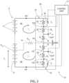
- the above-mentioned GFD stage 30 comprises a first circuit branch 32, electrically connected between the negative terminal HV - of the battery pack 8 and a reference terminal GND, connected to the ground of the vehicle 1 (not illustrated here; for example, this reference terminal GND may be connected to the body 2, or frame, of the above-mentioned vehicle 1); and a second circuit branch 33 electrically connected between the positive terminal HV + of the battery pack 8 and the same reference terminal GND.
- Each of the first and the second circuit branches 32, 33 implements a resistive divider between the negative terminal HV - , respectively positive terminal HV + , of the battery pack 8 and the reference terminal GND; the above-mentioned resistive dividers define a negative output terminal Out - , respectively, positive output terminal Out + of the GFD stage 30.
- each of the first and second circuit branches 32, 33 comprises a first resistive divider block 32a, 33a connected between the negative terminal HV - , respectively the positive terminal HV + of the battery pack 8 and the negative output terminal Out - , respectively, the positive output terminal Out + of the GFD stage 30; and a second resistive divider block 32b, 33b connected between the negative output terminal Out - , respectively, the positive output terminal Out + of the GFD stage 30 and the above-mentioned reference terminal GND.
- the negative and positive output terminals Out - , Out + are also connected to the control unit 31 of the BMS module 10.
- the first resistive divider block 32a, 33a of each of the circuit branches 32, 33 consists of a first series resistor 35', connected between the negative terminal HV - , respectively positive terminal HV + of the battery pack 8 and a respective internal node N in ; a second series resistor 35", connected between the respective internal node N in and the negative output terminal Out - , respectively, positive output terminal Out + of the GFD stage 30; and a respective switch element 36, connected in parallel to the first series resistor 35' and controlled by a respective control signal S c .
- control signals S c may be provided by the above-mentioned control unit 31 of the BMS module 10, in accordance with an operation logic (described in detail below).
- first and second series resistors 35', 35" have, in the implementation described, a same resistance value R, for example 3 M ⁇ ⁇ 1%.
- the above-mentioned resistive divider block 32b, 33b of the first and second circuit branches 32, 33 consists of a respective partition resistor 38, with a resistance value R p , for example of 14 k ⁇ ⁇ 1%.
- FIG. 3 schematically shows the presence of a partial or total interruption of isolation in the battery pack 8, due to a ground fault, schematically depicted by an isolation resistor 40, with resistance R iso that can be represented being connected between an isolation interruption point P ISO inside the battery pack 8, at a certain module or electrolytic cell 12, in which the fault has occurred, and ground (i.e., the above-mentioned reference terminal GND).
- a first and second circuit meshes 42, 44 can thus be defined, in which a first, respectively a second, mesh currents i 1 , i 2 flow (due to the dispersion, or leakage, towards ground).
- an unbalancing is caused with respect to a balanced condition (in the absence of ground faults and electric isolation interruption), in particular between the values of the voltages V Out - and V Out + at the negative output terminal Out - , respectively, the positive output terminal Out + of the GFD stage 30.
- the first circuit mesh 42 consists of the electrolytic cells 12 that are connected in series between the negative terminal HV - of the battery pack 8 and the isolation interruption point P ISO , the above-mentioned isolation resistor 40 and the first circuit branch 32 of the GFD stage 30.
- the second circuit mesh 44 consists of the remaining electrolytic cells 12 of the battery pack 8 in series between the above-mentioned isolation interruption point P ISO and the positive terminal HV + of the same battery pack 8, the above-mentioned isolation resistor 40 and the second circuit branch 33 of the GFD stage 30.
- isolation resistor 40 is, thus, shared between the first and second circuit meshes 42, 44.
- the GFD stage 30 allows both to estimate the resistance value R iso of the isolation resistor 40 and to locate the position of the isolation interruption point P ISO inside the battery pack 8, by means of the analysis of at least one (advantageously, both) of the above-mentioned first and second circuit meshes 42, 44.
- V x indicates the voltage across the electrochemical cells 12 that are part of this first circuit mesh 42 (in series between the negative terminal HV - of the battery pack 8 and the isolation interruption point P ISO )
- i 1 a indicates the current circulating in the first circuit mesh 42 in the first operating condition
- i 2 a indicates the current circulating in the second circuit mesh 44 in the same first operating condition ( i 2 a - i 1 a being, thus, the current that flows in the isolation resistor 40 in this first operating condition).
- R iso R ⁇ i 1 b ⁇ 2 ⁇ R ⁇ i 1 a + R p ⁇ i 1 b ⁇ i 1 a i 2 b ⁇ i 1 b ⁇ i 2 a + i 1 a
- the resistances R and R p are of a known value, based on design data of the GFD stage 30.
- the value of the unknown voltage V x can, thus, be obtained as a function of the value previously calculated for the resistance R iso , using the mesh equations previously indicated.
- V cell_av indicates an average cell voltage value of the electrochemical cells 12 of the battery pack 8 (for example a pre-set or design value).
- the above-mentioned position of the isolation interruption point P ISO could be calculated as a function of the value of the unknown voltage V x and of the measured value of the voltage drops on the electrochemical cells 12 of the circuit mesh being analysed (in this case, the cells starting from the negative terminal HV - ).
- control unit 31 of the BMS module 10 is also configured, in cooperation with the GFD stage 30, to calculate the above-mentioned value of the resistance R iso of the isolation resistor 40 and locate the position of the isolation interruption point P ISO , as a function of the above-mentioned values of the voltages V Out - and V Out + received as inputs by the negative output terminal Out - , respectively, the positive output terminal Out + of the same GFD stage 30.
- control unit 31 is designed to implement suitable software instructions of a processing program stored in a corresponding non-volatile memory (not illustrated here).
- control unit 31 is configured to control the opening of the respective switch element 36 of the first and/or second circuit branches 32, 33, so as to implement the above-mentioned first and second operating conditions and, consequently, allow the possibility to assess the two mesh equations previously discussed, for estimating the value and position of the isolation resistance.
- An additional aspect of the present solution envisages that, for the calculation of the above-mentioned value of the resistance R iso of the isolation resistor 40 and for locating the position of the isolation interruption point P ISO , the first circuit mesh 42 or the second circuit mesh 44 is alternatively used, depending on the different unbalance detected between the first and second circuit meshes 42, 44 (in other words, as a function of the different values of the first, respectively second, mesh currents i 1 , i 2 ).
- control unit 31 may be, in this case, configured to carry out a preliminary evaluation of the value of the mesh currents i 1 , i 2 (under the same operating conditions, whether the first or second operating condition) and use the first circuit mesh 42 if the first mesh current i 1 is greater than the second mesh current i 2 , or the second circuit mesh 44 if the first mesh current i 1 is less than the second mesh current i 2 (if the two current values are basically equal, the first or the second circuit mesh 42, 44 may be chosen).
- This preliminary evaluation may, advantageously, allow to increase precision in estimating the value of the isolation resistance and, in addition, in locating the fault inside the battery pack 8.
- the above-mentioned preliminary evaluation may be carried out as a function of the isolation resistance values measured (in a known way, not described in detail here) at the positive and negative terminals HV + , HV - of the battery pack 8.
- the first circuit mesh 42 may be, in this case, used for the evaluation of the isolation if the value of the isolation resistance at the negative terminal HV - of the battery pack 8 is greater than the isolation resistance at the positive terminal HV + ; similarly, the second circuit mesh 44 may be used if the value of the isolation resistance at the negative terminal HV - of the battery pack 8 is less than the isolation resistance at the positive terminal HV + .
- the measurements made in relation to the isolation resistance may be implemented at pre-defined intervals or at the occurrence of particular events, for example if the measurements taken relating to the isolation resistances at the positive and negative terminals HV + , HV - of the battery pack 8 is indicative of a possible ground fault (the type of algorithm that can be implemented being selectable).
- the solution described allows to determine, in case of an isolation loss in the battery pack, not just an estimate of the resulting isolation resistance, but also to locate, during a diagnosis phase, the position of the isolation loss inside the same battery pack.
- the present Applicant has demonstrated, with simulations and experimental tests, the possibility of obtaining very accurate estimates of the isolation resistance value, as well as excellent precision in locating the isolation loss inside the battery pack.
Landscapes
- Engineering & Computer Science (AREA)
- Power Engineering (AREA)
- Life Sciences & Earth Sciences (AREA)
- Sustainable Development (AREA)
- Sustainable Energy (AREA)
- Transportation (AREA)
- Mechanical Engineering (AREA)
- Physics & Mathematics (AREA)
- General Physics & Mathematics (AREA)
- Secondary Cells (AREA)
- Measurement Of Resistance Or Impedance (AREA)
Abstract
An isolation resistance system for a battery (5) of a vehicle (1) having a battery pack (8) with a plurality of electrolytic cells (12) connected in series between a positive terminal (HV+) and a negative terminal (HV-). A ground fault detection stage (30) is coupled to the positive and negative terminals and consists of: a first circuit branch (32), electrically coupled between the negative terminal and a reference terminal (GND), connected to the ground of the vehicle (1); and a second circuit branch (33), electrically coupled between the positive terminal and the reference terminal (GND). The first and the second circuit branches implement a respective resistive divider defining a negative output terminal (Out-), respectively, a positive output terminal (Out+), of the ground fault detection stage having, in use, a respective output voltage (VOut -, VOut +). A control unit (31) operatively coupled to the negative and positive output terminals determines an isolation resistance value (Riso ) associated with an isolation loss of the battery pack and locates an isolation loss position within the battery pack, as a function of the values of the output voltages (VOut -, VOut +) at the positive and negative output terminals of the ground fault detection stage (30).
Description
- This patent application claims priority from
Italian patent application no. 102023000024207 filed on November 15, 2023 - The present solution relates to an isolation resistance evaluation system for a high-voltage battery (HVB), in particular for an electrically driven, hybrid or fully electric vehicle, so called BEV (Battery Electric Vehicle).
- This solution may find preferable application in a BMS (Battery Management System) module provided with a Ground Fault Detection (GFD) system of an electric or hybrid vehicle having a high-voltage battery pack, to which the following discussion will make explicit reference without any loss of generality.
- As is known, electric or hybrid motor vehicles are provided with an electric or hybrid drive assembly, which is designed to drive at least one wheel resting on the ground; a high-voltage, rechargeable battery pack, which is designed to accumulate a given amount of electrical energy to supply the electric or hybrid drive assembly; and an electronically controlled inverter, which is coupled between the battery pack and the drive assembly and is designed to transform, based on commands given by the driver of the vehicle, the direct current electrical energy coming from the battery pack into alternating current for the drive assembly.
- In a known manner, the battery pack is internally provided with a management module, so-called BMS module, which interacts with the vehicle electronics and is designed to manage the operation and monitor the operating state of the battery pack, for example so as to avoid operation beyond safe conditions.
- In particular, the BMS module is designed to control and manage the group of electrochemical cells of the battery pack, monitoring their charge status, temperature, voltage and/or other parameters, in order, for example, to balance the charge status in case of an unbalance between the various electrochemical cells.
- Given that the battery packs of current motor vehicles may even reach nominal voltages of 800 V (generally operating at high voltages, ranging between 400 and 800 V), it is important to be able to detect any ground faults of the battery pack that may compromise the electrical isolation and be hazardous for people and/or the vehicle's low-voltage circuits that share the same ground connection.
- These faults may, for example, be due to ageing of the electrical components, various kinds of stress (mechanical, electrical, thermal, or, in general, environmental) or to accidents to which the battery pack may be subjected, such as, for example, the puncturing of a corresponding sealed container in which the electrolytic cells are housed. When a ground fault occurs, a significant reduction in the electrical resistance associated with the isolation results; this entails the flow of a given leakage current, which may not be negligible.
- It is, therefore, envisaged that the battery packs are equipped with ground fault detection circuits that are able to assess (potentially by means of suitable estimation) the electrical resistance between the positive pole of the battery pack and ground and/or between the negative pole of the same battery pack and ground, in particular operating conditions of the battery pack specified by the current regulations.
- These ground fault detection circuits may, advantageously, be included in the BMS module of the high-voltage battery. In this case, the BMS module thus also has the function of monitoring the above-mentioned isolation resistance of the battery pack, being, for example, configured to interrupt, by means of suitable circuit interruption elements, the supply of loads by the same battery pack if there is a change in the isolation resistance that potentially is indicative of a ground fault.
- This Applicant has realized that, despite the important function performed, the above-mentioned ground fault detection circuits currently may only provide an overall indication of the electrical isolation of the battery pack and, at the most, a qualitative evaluation of the state of electrical isolation inside the same battery pack, with the operating limits that derive from this.
- In particular, known solutions do not enable to locate possible isolation losses inside the battery pack, being, at most, only able to determine whether the isolation inside the battery pack has deteriorated and, if so, to signal the need to replace the whole battery pack.
- The aim of the present invention is, in general, to overcome the limitations associated with the current solutions and, in particular, to provide a solution for evaluating the isolation resistance of a high-voltage battery, in particular for an electric motor vehicle, which is able to estimate the isolation resistance and, in addition, locate a position of the electrolytic cell inside the battery pack where the electric isolation is damaged or, in any case, compromised.
- In view of the object indicated above, a system as defined in the attached claims is provided, according to the present invention.
- The present invention will now be described with reference to the attached drawings that illustrate a nonlimiting embodiment thereof, in which:
-
Figure 1 is a schematic perspective view of an electric or hybrid motor vehicle provided with a battery pack having a BMS module, with parts removed for clarity; -
Figure 2 is a block diagram of a high-voltage battery of the motor vehicle ofFigure 1 ; and -
Figure 3 is a circuit diagram of an isolation resistance evaluation system for the high-voltage battery ofFigure 2 . - In
Figure 1 , reference 1 denotes, as a whole, a vehicle, in particular an electric or hybrid motor vehicle that has abody 2 resting on the ground by means of wheels 3 and comprising: an electric orhybrid drive assembly 4, including at least one synchronous or asynchronous electric motor, designed to drive in rotation at least one of the wheels 3; and a rechargeable, high-voltage battery (HVB) 5 that is able to accumulate a given quantity of electrical energy to supply the above-mentioneddrive assembly 4. - The
drive assembly 4 and the high-voltage battery 5 are housed inside thebody 2, in the example illustrated the electric orhybrid drive assembly 4 being positioned in the rear part and the high-voltage battery 5 in the front part of thebody 2. - In a known manner, not illustrated herein, an electrical unit, in particular including an electronically controlled inverter, is coupled between the high-
voltage battery 5 and thedrive assembly 4 to transform, based on commands given by the driver of the vehicle, the direct current electrical energy coming from the high-voltage battery 5 into alternating current electrical energy for thedrive assembly 4. - The high-
voltage battery 5 has, for example, a nominal capacity greater than or equal to 50 kWh and a nominal voltage ranging between 400 V and 800 Volt, in particular equal to 800 V. - As schematically shown in the above-mentioned
Figure 1 , the high-voltage battery 5 internally comprises abattery pack 8 and aBMS module 10, operationally coupled to thebattery pack 8, to manage and supervise its operation. -
Figure 2 schematically shows, in a more detailed manner, a possible implementation of the above-mentioned high-voltage battery 5. - In particular, the
battery pack 8 consists of a given number of modules orelectrochemical cells 12, connected in series between a positive terminal HV+ and a negative terminal HV-, between which a battery voltage VHV is provided, which has a high value, for example in the range of 400 - 800 V. - In the embodiment illustrated, a first circuit interruption element (contactor) 14a is arranged between the positive terminal HV+ and a positive output node P1 of the
battery pack 8, by means of the interposition of acurrent sensor element 15. - Similarly, a second circuit interruption element (contactor) 14b is arranged between the negative terminal HV- and a negative output node P2 of the
battery pack 8, by means of the interposition, in this case, of afuse element 16. - The above-mentioned positive and negative output nodes P1, P2 are coupled to a high-voltage output bus, here not illustrated, of the
battery pack 8, designed to transport electrical energy towards loads (in particular towards the electric or hybrid drive assembly 4). - The
battery pack 8 also comprises a Cell Supervisor Circuit (CSC) 18, comprising a plurality of Analog Front End (AFE)stages 19, each coupled to a respectiveelectrochemical cell 12. Thissupervisor circuit 18 has, among other features, the function of monitoring the voltage of the individualelectrochemical cells 12 and balancing the voltages of the sameelectrochemical cells 12. - In the implementation illustrated, the
BMS module 10 comprises: - a
first management stage 20, coupled to thecell supervisor circuit 18 and configured to manage operation thereof; - a
second management stage 22, coupled to the above-mentioned, high-voltage bus and configured to manage operation thereof; - a
third management stage 24, coupled to the first and secondcircuit interruption elements circuit interruption elements - a
fourth management stage 26, coupled to thecurrent sensor element 15 and to thefuse element 16 and configured to manage their operation. - The
BMS module 10 also comprises a Ground Fault Detection (GFD)stage 30 coupled to the above-mentioned positive HV+ and negative HV- terminals of thebattery pack 8 and configured to perform isolation resistance evaluations for the high-voltage battery 5. - In particular, according to one aspect of this solution, the ground
fault detection stage 30 is configured to estimate the isolation resistance towards the ground and, in addition, locate inside the battery pack 8 a position of theelectrochemical cell 12 where the electrical isolation is damaged or, in any case, compromised. - The above-mentioned
BMS module 10 further comprises acontrol unit 31, having a micro-processor, micro-controller, or similar digital processing unit, operationally coupled to the above-mentioned first, second, third, andfourth management stages GFD stage 30, so as to control operation and functioning thereof, also as a function of controls received from outside, for example from an Electronic Control Unit (ECU) of the motor vehicle (not illustrated here). - Specifically, and with reference to
Figure 3 , according to one embodiment of this solution, the above-mentionedGFD stage 30 comprises afirst circuit branch 32, electrically connected between the negative terminal HV- of thebattery pack 8 and a reference terminal GND, connected to the ground of the vehicle 1 (not illustrated here; for example, this reference terminal GND may be connected to thebody 2, or frame, of the above-mentioned vehicle 1); and asecond circuit branch 33 electrically connected between the positive terminal HV+ of thebattery pack 8 and the same reference terminal GND. - Each of the first and the
second circuit branches battery pack 8 and the reference terminal GND; the above-mentioned resistive dividers define a negative output terminal Out-, respectively, positive output terminal Out+ of theGFD stage 30. - Specifically, each of the first and
second circuit branches resistive divider block battery pack 8 and the negative output terminal Out-, respectively, the positive output terminal Out+ of theGFD stage 30; and a secondresistive divider block GFD stage 30 and the above-mentioned reference terminal GND. - As schematically illustrated, the negative and positive output terminals Out-, Out+ are also connected to the
control unit 31 of theBMS module 10. - More specifically, the first
resistive divider block circuit branches battery pack 8 and a respective internal node Nin; asecond series resistor 35", connected between the respective internal node Nin and the negative output terminal Out-, respectively, positive output terminal Out+ of theGFD stage 30; and arespective switch element 36, connected in parallel to the first series resistor 35' and controlled by a respective control signal Sc. - As schematically illustrated, the control signals Sc may be provided by the above-mentioned
control unit 31 of theBMS module 10, in accordance with an operation logic (described in detail below). - In particular, the first and
second series resistors 35', 35" have, in the implementation described, a same resistance value R, for example 3 MΩ ± 1%. - The above-mentioned
resistive divider block second circuit branches respective partition resistor 38, with a resistance value Rp, for example of 14 kΩ ± 1%. - The same
Figure 3 schematically shows the presence of a partial or total interruption of isolation in thebattery pack 8, due to a ground fault, schematically depicted by anisolation resistor 40, with resistance Riso that can be represented being connected between an isolation interruption point PISO inside thebattery pack 8, at a certain module orelectrolytic cell 12, in which the fault has occurred, and ground (i.e., the above-mentioned reference terminal GND). - A first and
second circuit meshes GFD stage 30. - Specifically, the
first circuit mesh 42 consists of theelectrolytic cells 12 that are connected in series between the negative terminal HV- of thebattery pack 8 and the isolation interruption point PISO, the above-mentionedisolation resistor 40 and thefirst circuit branch 32 of theGFD stage 30. - The
second circuit mesh 44 consists of the remainingelectrolytic cells 12 of thebattery pack 8 in series between the above-mentioned isolation interruption point PISO and the positive terminal HV+ of thesame battery pack 8, the above-mentionedisolation resistor 40 and thesecond circuit branch 33 of theGFD stage 30. - The above-mentioned
isolation resistor 40 is, thus, shared between the first andsecond circuit meshes - As indicated above, according to one aspect of the present solution, the
GFD stage 30 allows both to estimate the resistance value Riso of theisolation resistor 40 and to locate the position of the isolation interruption point PISO inside thebattery pack 8, by means of the analysis of at least one (advantageously, both) of the above-mentioned first andsecond circuit meshes - In this regard, and initially considering, by way of example, the
first circuit mesh 42, the mesh equation in a first operating condition, wherein therespective switch element 36 is open (theswitch element 36 of thesecond circuit mesh 44 being closed), is the following:
electrochemical cells 12 that are part of this first circuit mesh 42 (in series between the negative terminal HV- of thebattery pack 8 and the isolation interruption point PISO), i 1a indicates the current circulating in thefirst circuit mesh 42 in the first operating condition and i 2a indicates the current circulating in thesecond circuit mesh 44 in the same first operating condition (i 2a - i 1a being, thus, the current that flows in theisolation resistor 40 in this first operating condition). - Similarly, one can define, for the same
first circuit mesh 42, the mesh equation in a second operating condition, wherein therespective switch element 36 is closed (again, theswitch element 36 of thesecond circuit mesh 44 being closed):
first circuit mesh 42 in the second operating condition and i 2b indicates the current circulating in thesecond circuit mesh 44 in the same second operating condition (i 2b - i 1b being, thus, the current flowing in theisolation resistor 40 in this second operating condition). - Thus, two equations with two unknowns are obtained, Vx and Riso , that may be resolved, for example, to obtain the following expression for the resistance Riso :

- In particular, it is underlined that the resistances R and Rp are of a known value, based on design data of the
GFD stage 30. - In addition, the values of the currents circulating in the first and second circuit meshes 42, 44, in the first and second operating conditions (specifically, i 1a , i 1b , i 2a , i 2b ) may be calculated based on the values of the voltages VOut -and VOut + at the negative output terminal Out-, respectively, the positive output terminal Out+ of the
GFD stage 30 and of the known value of the above-mentioned resistance Rp , in particular by means of the following relations:
- The value of the unknown voltage Vx can, thus, be obtained as a function of the value previously calculated for the resistance Riso, using the mesh equations previously indicated.
- Advantageously, based on this value of the unknown voltage Vx it is also possible to calculate the position of the isolation inside the
battery pack 8, or locate the above-mentioned isolation interruption point PISO. - For example, the following expression can be used to estimate the position of the isolation interruption point PISO:

electrochemical cells 12 of the battery pack 8 (for example a pre-set or design value). - Alternatively, should the voltage drops on the individual
electrochemical cells 12 be know (for example, using the information provided by thecell supervisor circuit 18 of the battery pack 8), the above-mentioned position of the isolation interruption point PISO could be calculated as a function of the value of the unknown voltage Vx and of the measured value of the voltage drops on theelectrochemical cells 12 of the circuit mesh being analysed (in this case, the cells starting from the negative terminal HV-). - What was described in detail for the
first circuit mesh 42 may clearly be applied in an entirely similar manner for thesecond circuit mesh 44, with clear changes in the mesh equations to take into account the corresponding circuit components. - In one possible embodiment, the
control unit 31 of theBMS module 10 is also configured, in cooperation with theGFD stage 30, to calculate the above-mentioned value of the resistance Riso of theisolation resistor 40 and locate the position of the isolation interruption point PISO, as a function of the above-mentioned values of the voltages VOut -and VOut + received as inputs by the negative output terminal Out-, respectively, the positive output terminal Out+ of thesame GFD stage 30. - To this end, the
control unit 31 is designed to implement suitable software instructions of a processing program stored in a corresponding non-volatile memory (not illustrated here). - In particular, the
control unit 31 is configured to control the opening of therespective switch element 36 of the first and/orsecond circuit branches - An additional aspect of the present solution envisages that, for the calculation of the above-mentioned value of the resistance Riso of the
isolation resistor 40 and for locating the position of the isolation interruption point PISO, thefirst circuit mesh 42 or thesecond circuit mesh 44 is alternatively used, depending on the different unbalance detected between the first and second circuit meshes 42, 44 (in other words, as a function of the different values of the first, respectively second, mesh currents i1, i2). - In particular, the above-mentioned
control unit 31 may be, in this case, configured to carry out a preliminary evaluation of the value of the mesh currents i1, i2 (under the same operating conditions, whether the first or second operating condition) and use thefirst circuit mesh 42 if the first mesh current i1 is greater than the second mesh current i2, or thesecond circuit mesh 44 if the first mesh current i1 is less than the second mesh current i2 (if the two current values are basically equal, the first or thesecond circuit mesh - This preliminary evaluation may, advantageously, allow to increase precision in estimating the value of the isolation resistance and, in addition, in locating the fault inside the
battery pack 8. - Alternatively, the above-mentioned preliminary evaluation may be carried out as a function of the isolation resistance values measured (in a known way, not described in detail here) at the positive and negative terminals HV+, HV-of the
battery pack 8. - In particular, the
first circuit mesh 42 may be, in this case, used for the evaluation of the isolation if the value of the isolation resistance at the negative terminal HV- of thebattery pack 8 is greater than the isolation resistance at the positive terminal HV+; similarly, thesecond circuit mesh 44 may be used if the value of the isolation resistance at the negative terminal HV- of thebattery pack 8 is less than the isolation resistance at the positive terminal HV+. - It may also be seen that the measurements made in relation to the isolation resistance may be implemented at pre-defined intervals or at the occurrence of particular events, for example if the measurements taken relating to the isolation resistances at the positive and negative terminals HV+, HV- of the
battery pack 8 is indicative of a possible ground fault (the type of algorithm that can be implemented being selectable). - The advantages that this solution enables are evident from what has been discussed.
- In particular, the solution described allows to determine, in case of an isolation loss in the battery pack, not just an estimate of the resulting isolation resistance, but also to locate, during a diagnosis phase, the position of the isolation loss inside the same battery pack.
- In this regard, the present Applicant has demonstrated, with simulations and experimental tests, the possibility of obtaining very accurate estimates of the isolation resistance value, as well as excellent precision in locating the isolation loss inside the battery pack.
- This solution thus allow not only to implement suitable actions to limit the risks, for example disconnecting the battery pack from loads by opening the contactors coupled to the positive and negative terminals of the battery pack; but also to implement targeted strategies to repair faults, for example with the possibility of replacing one or more modules inside the battery pack and not the whole battery pack (with clear benefits both in terms of costs and time).
- Lastly, it is clear that modifications and variations may be made to that described herein without departing from the scope of the present invention, as set forth in the claims.
- In particular, it is clear that the solution described can, advantageously, be applied in various fields of use, without being limited to applications for electric or hybrid vehicles, for example for drive batteries, used with the function of supplying drives and/or electric motors in industrial vehicles, robots, or electric machinery.
Claims (15)
- An isolation resistance evaluation system for a battery (5) of a vehicle (1), having a battery pack (8) with a plurality of electrolytic cells (12) connected in series between a positive terminal (HV+) and a negative terminal (HV-),comprising a ground fault detection stage (30) designed to be coupled to said positive terminal (HV+) and to said negative terminal (HV-) of the battery pack (8) and including: a first circuit branch (32) electrically coupled between the negative terminal (HV-) of the battery pack (8) and a reference terminal (GND) connected to the ground of the vehicle (1); and a second circuit branch (33) electrically coupled between the positive terminal (HV+) of the battery pack (8) and said reference terminal (GND), wherein the first and the second circuit branches (32, 33) implement a respective resistive divider connected between the negative terminal (HV-), respectively the positive terminal (HV+), of the battery pack (8) and the reference terminal (GND) and defining a negative output terminal (Out-), respectively a positive output terminal (Out+), of the ground fault detection stage (30) having, in use, a respective output voltage (VOut -, VOut +),characterized by comprising a control unit (31) operatively coupled to said negative output terminal (Out-) and positive output terminal (Out+) and configured, in cooperation with the ground fault detection stage (30), to determine an isolation resistance value (Riso ) associated with an isolation loss of the battery pack (8) and to locate an isolation loss position within the battery pack (8) as a function of the values of the output voltages (VOut -, VOut +) at the positive and negative output terminals (Out-, Out+) of the ground fault detection stage (30).
- The system according to claim 1, wherein said first and second circuit branches (32, 33) are designed to form a first, respectively a second, circuit mesh (42, 44), with an isolation resistor (40), having said isolation resistance (Riso) and connected between an isolation interruption point (PISO) within said battery (8), at said isolation loss position, and said reference terminal (GND), said isolation resistor (40) being shared by said first and second circuit meshes (42, 44); and wherein said ground fault detection stage (30) is configured to estimate the value of the isolation resistance (Riso) and to locate the isolation loss position through the analysis of at least one of said first and second circuit meshes (42, 44).
- The system according to claim 2, wherein said control unit (31) is configured to implement: a first operating condition of said ground fault detection stage (30), which is associated with a first mesh equation of said at least one of said first and second circuit meshes (42, 44); and a second operating condition of said ground fault detection stage (30), which is associated with a second mesh equation of said at least one of said first and second circuit meshes (42, 44); and wherein said first and second mesh equations form a system of two equations with two unknowns, corresponding to said value of the isolation resistance (Riso) and to an isolation voltage (Vx ) across the electrochemical cells (12) that are part of said at least one of said first and second circuit meshes (42, 44).
- The system according to claim 3, wherein the position of the isolation interruption point (PISO) within the battery pack (8) is determined as:

- The system according to claim 3 or 4, wherein said first circuit mesh (42) is formed by the electrolytic cells (12) series-connected between the negative terminal (HV-) of said battery pack (8) and the isolation interruption point (PISO), by the isolation resistor (40) and by said first circuit branch (32) of the ground fault detection stage (30); and said second circuit mesh (44) is formed by the remaining electrolytic cells (12) of said battery pack (8) series-connected between the isolation interruption point (PISO) and the positive terminal (HV+) of the battery pack (8), by the isolation resistor (40) and by the second circuit branch (33) of the ground fault detection stage (30).
- The system according to any of claims 3-5, wherein said respective resistive divider comprises a first resistive divider block (32a, 33a) connected between the negative terminal (HV-), respectively the positive terminal (HV+), of the battery pack (8) and the negative output terminal (Out-), respectively the positive output terminal (Out+), of the ground fault detection stage (30); and a second resistive divider block (32b, 33b) connected between the negative output terminal (Out-), respectively the positive output terminal (Out+), of the ground fault detection stage (30) and said reference terminal (GND).
- The system according to claim 6, wherein said first resistive divider block (32a, 33a) is formed by a first series resistor (35') connected between the negative terminal (HV-), respectively the positive terminal (HV+), of the battery pack (8) and a respective internal node (Nin); a second series resistor (35") connected between the respective internal node (Nin) and the negative output terminal (Out-), respectively the positive output terminal (Out+), of the ground fault detection stage (30); and a respective switch element (36) connected in parallel to the first series resistor (35') and controlled by a respective control signal (Sc); wherein said control unit (31) is configured to provide said respective control signal (Sc) in order to implement said first operating condition, corresponding to a first operating state, either open or closed, of said respective switch element (36), and said second operating condition, corresponding to a second operating state, either open or closed, different from said first operating state, of said respective switch element (36) .
- The system according to any of claims 2-7, wherein said ground fault detection stage (30) is configured to estimate the value of the isolation resistance (Riso) and to locate the isolation loss position, alternatively through the analysis of the first circuit mesh (42) or of the second circuit mesh (44), as a function of a different unbalance detected between said first and second circuit meshes (42, 44) relative to a balanced condition in the absence of ground faults and electric isolation interruption.
- A battery (5) for a vehicle (1) having a battery pack (8) with a plurality of electrolytic cells (12) connected in series between a positive terminal (HV+) and a negative terminal (HV-) and a BMS module (10), operatively coupled to the battery pack (8) for managing and controlling operation thereof; further comprising an isolation resistance evaluation system according to any of the preceding claims.
- The battery (5) according to claim 9, wherein said BMS module (10) includes said isolation resistance evaluation system.
- The battery (5) according to claim 9 or 10, of a high-voltage type, with an operating voltage between said positive terminal (HV+) and negative terminal (HV-) in the range 400-800 V.
- A motor vehicle (1) having wheels (3) resting on the ground and comprising: an electric or hybrid drive assembly (4) designed to cause rotation of at least one of said wheels (3); and a battery (5) according to any one of claims 9-11, designed to store a given quantity of electrical energy to be supplied to said drive assembly (4).
- An isolation resistance evaluation method for a battery (5) of a vehicle (1) having a battery pack (8) with a plurality of electrolytic cells (12) connected in series between a positive terminal (HV+) and a negative terminal (HV-),comprising defining a first circuit branch (32) electrically coupled between the negative terminal (HV-) of the battery pack (8) and a reference terminal (GND) connected to the ground of the vehicle (1); and a second circuit branch (33) electrically coupled between the positive terminal (HV+) of the battery pack (8) and said reference terminal (GND), wherein the first and the second circuit branches (32, 33) implement a respective resistive divider connected between the negative terminal (HV-), respectively the positive terminal (HV+), of the battery pack (8) and the reference terminal (GND), defining a negative output terminal (Out-), respectively a positive output terminal (Out+), having in use a respective output voltage VOut -, VOut +),characterized by comprising: determining an isolation resistance value (Riso ) associated with an isolation loss of the battery pack (8) and locating an isolation loss position inside the battery pack (8), as a function of the values of the output voltages (VOut -, VOut +) at the positive and negative output terminals (Out-, Out+).
- The method according to claim 13, wherein said first and second circuit branches (32, 33) are designed to form a first and, respectively, a second circuit mesh (42, 44) with an isolation resistor (40) having said isolation resistance (Riso) and connected between an isolation interruption point (PISO) inside said battery (8), at said isolation loss position, and said reference terminal (GND), said isolation resistor (40) being shared by said first and second circuit meshes (42, 44); comprising estimating the value of the isolation resistance (Riso) and locating the isolation loss position through the analysis of at least one of said first and second circuit meshes (42, 44).
- The method according to claim 14, wherein estimating comprising implementing: a first operating condition of said ground fault detection stage (30), which is associated with a first mesh equation of said at least one of said first and second circuit meshes (42, 44); and a second operating condition of said ground fault detection stage (30), which is associated with a second mesh equation of said at least one of said first and second circuit meshes (42, 44); and wherein said first and second mesh equations form a system of two equations with two unknowns, corresponding to said value of the isolation resistance (Riso) and to an isolation voltage (Vx ) across the electrochemical cells (12) that are part of said at least one of said first and second circuit meshes (42, 44).
Applications Claiming Priority (1)
| Application Number | Priority Date | Filing Date | Title |
|---|---|---|---|
| IT102023000024207A IT202300024207A1 (en) | 2023-11-15 | 2023-11-15 | INSULATION RESISTANCE EVALUATION SYSTEM FOR A HIGH VOLTAGE BATTERY, PARTICULARLY FOR AN ELECTRIC-PROPULSION VEHICLE |
Publications (1)
| Publication Number | Publication Date |
|---|---|
| EP4556914A1 true EP4556914A1 (en) | 2025-05-21 |
Family
ID=89897712
Family Applications (1)
| Application Number | Title | Priority Date | Filing Date |
|---|---|---|---|
| EP24212623.3A Pending EP4556914A1 (en) | 2023-11-15 | 2024-11-13 | Isolation resistance evaluation system for a high voltage battery, in particular for an electric vehicle |
Country Status (2)
| Country | Link |
|---|---|
| EP (1) | EP4556914A1 (en) |
| IT (1) | IT202300024207A1 (en) |
Citations (6)
| Publication number | Priority date | Publication date | Assignee | Title |
|---|---|---|---|---|
| CN106501611A (en) * | 2016-10-28 | 2017-03-15 | 深圳市航盛电子股份有限公司 | Insulation resistance detection method and device |
| CN106997007A (en) * | 2017-05-25 | 2017-08-01 | 上海炙云新能源科技有限公司 | Electric automobile direct-current high-voltage system insulating resistance measurement apparatus and its measuring method |
| CN111060748A (en) * | 2019-12-04 | 2020-04-24 | 珠海格力电器股份有限公司 | Selective electric vehicle insulation resistance detection method and system |
| WO2020135703A1 (en) * | 2018-12-29 | 2020-07-02 | 蜂巢能源科技有限公司 | Insulation detection system based on full-bridge insulation detection circuit and electric automobile |
| CN113791278A (en) * | 2021-09-30 | 2021-12-14 | 蜂巢能源科技有限公司 | Battery pack insulation resistance detection method, device, battery pack and vehicle |
| CN114200210A (en) * | 2021-12-07 | 2022-03-18 | 珠海格力电器股份有限公司 | Insulation resistance detection system and method and automobile |
-
2023
- 2023-11-15 IT IT102023000024207A patent/IT202300024207A1/en unknown
-
2024
- 2024-11-13 EP EP24212623.3A patent/EP4556914A1/en active Pending
Patent Citations (6)
| Publication number | Priority date | Publication date | Assignee | Title |
|---|---|---|---|---|
| CN106501611A (en) * | 2016-10-28 | 2017-03-15 | 深圳市航盛电子股份有限公司 | Insulation resistance detection method and device |
| CN106997007A (en) * | 2017-05-25 | 2017-08-01 | 上海炙云新能源科技有限公司 | Electric automobile direct-current high-voltage system insulating resistance measurement apparatus and its measuring method |
| WO2020135703A1 (en) * | 2018-12-29 | 2020-07-02 | 蜂巢能源科技有限公司 | Insulation detection system based on full-bridge insulation detection circuit and electric automobile |
| CN111060748A (en) * | 2019-12-04 | 2020-04-24 | 珠海格力电器股份有限公司 | Selective electric vehicle insulation resistance detection method and system |
| CN113791278A (en) * | 2021-09-30 | 2021-12-14 | 蜂巢能源科技有限公司 | Battery pack insulation resistance detection method, device, battery pack and vehicle |
| CN114200210A (en) * | 2021-12-07 | 2022-03-18 | 珠海格力电器股份有限公司 | Insulation resistance detection system and method and automobile |
Also Published As
| Publication number | Publication date |
|---|---|
| IT202300024207A1 (en) | 2025-05-15 |
Similar Documents
| Publication | Publication Date | Title |
|---|---|---|
| US9931960B2 (en) | Electric or hybrid vehicle battery pack voltage measurement functional assessment and redundancy | |
| EP3455917B1 (en) | Method and apparatus of a modular management system for energy storage cells | |
| US7548821B2 (en) | Battery management system and driving method thereof | |
| EP3182146B1 (en) | Electronic device, system and method for insulation resistance measurements with functions of self-diagnosis and diagnosis of insulation loss with respect to ground of an energized electrical apparatus | |
| EP2360485B1 (en) | Battery management system and driving method thereof | |
| EP1873542B1 (en) | Apparatus and method for estimating charge of a battery | |
| US9770997B2 (en) | Detection of imbalance across multiple battery cells measured by the same voltage sensor | |
| EP1607727B1 (en) | Method for detecting abnormality of temperature sensors, and power supply apparatus | |
| US9634361B2 (en) | Battery system and associated method for determining the internal resistance of battery cells or battery modules of said battery system | |
| WO2021092109A1 (en) | System for charging a series of connected batteries | |
| CN111435150B (en) | Method and system for estimating energy of residual battery pack using charge state variation range of battery pack | |
| US20170057372A1 (en) | Electric or hybrid vehicle battery pack voltage measurement | |
| KR102701207B1 (en) | Apparatus for diagnosing isolation of battery | |
| KR101189582B1 (en) | Voltage sensing system for detecting disconnection of voltage sensing line of battery | |
| EP3699616B1 (en) | Detection circuit and method | |
| EP4084187A1 (en) | Battery control device and battery system | |
| US12183898B2 (en) | Current sensor fault diagnostics | |
| EP4409308B1 (en) | Estimating battery state of health | |
| EP3872920B1 (en) | BATTERY CONTROL DEVICE | |
| US12365264B2 (en) | Voltage measurement method and operating method for a vehicle on-board power supply system | |
| US11125786B2 (en) | Method for detecting an internal short circuit in a first electrical energy storage unit of an electrical energy storage device | |
| EP4556914A1 (en) | Isolation resistance evaluation system for a high voltage battery, in particular for an electric vehicle | |
| EP4099027B1 (en) | Earth fault detection apparatus | |
| Thobde et al. | State of Charge (SoC) algorithm for Battery Management System (BMS) | |
| JP7377743B2 (en) | battery management device |
Legal Events
| Date | Code | Title | Description |
|---|---|---|---|
| PUAI | Public reference made under article 153(3) epc to a published international application that has entered the european phase |
Free format text: ORIGINAL CODE: 0009012 |
|
| STAA | Information on the status of an ep patent application or granted ep patent |
Free format text: STATUS: THE APPLICATION HAS BEEN PUBLISHED |
|
| AK | Designated contracting states |
Kind code of ref document: A1 Designated state(s): AL AT BE BG CH CY CZ DE DK EE ES FI FR GB GR HR HU IE IS IT LI LT LU LV MC ME MK MT NL NO PL PT RO RS SE SI SK SM TR |
|
| STAA | Information on the status of an ep patent application or granted ep patent |
Free format text: STATUS: REQUEST FOR EXAMINATION WAS MADE |
|
| 17P | Request for examination filed |
Effective date: 20251120 |