EP4556856A1 - Electronic device, control method, and non-transitory computer readable storage medium - Google Patents
Electronic device, control method, and non-transitory computer readable storage medium Download PDFInfo
- Publication number
- EP4556856A1 EP4556856A1 EP24212811.4A EP24212811A EP4556856A1 EP 4556856 A1 EP4556856 A1 EP 4556856A1 EP 24212811 A EP24212811 A EP 24212811A EP 4556856 A1 EP4556856 A1 EP 4556856A1
- Authority
- EP
- European Patent Office
- Prior art keywords
- common object
- image
- feature points
- data
- map
- Prior art date
- Legal status (The legal status is an assumption and is not a legal conclusion. Google has not performed a legal analysis and makes no representation as to the accuracy of the status listed.)
- Pending
Links
Images




Classifications
-
- G—PHYSICS
- G01—MEASURING; TESTING
- G01C—MEASURING DISTANCES, LEVELS OR BEARINGS; SURVEYING; NAVIGATION; GYROSCOPIC INSTRUMENTS; PHOTOGRAMMETRY OR VIDEOGRAMMETRY
- G01C21/00—Navigation; Navigational instruments not provided for in groups G01C1/00 - G01C19/00
- G01C21/38—Electronic maps specially adapted for navigation; Updating thereof
- G01C21/3804—Creation or updating of map data
-
- G—PHYSICS
- G01—MEASURING; TESTING
- G01C—MEASURING DISTANCES, LEVELS OR BEARINGS; SURVEYING; NAVIGATION; GYROSCOPIC INSTRUMENTS; PHOTOGRAMMETRY OR VIDEOGRAMMETRY
- G01C21/00—Navigation; Navigational instruments not provided for in groups G01C1/00 - G01C19/00
- G01C21/26—Navigation; Navigational instruments not provided for in groups G01C1/00 - G01C19/00 specially adapted for navigation in a road network
- G01C21/34—Route searching; Route guidance
- G01C21/36—Input/output arrangements for on-board computers
- G01C21/3602—Input other than that of destination using image analysis, e.g. detection of road signs, lanes, buildings, real preceding vehicles using a camera
-
- G—PHYSICS
- G01—MEASURING; TESTING
- G01C—MEASURING DISTANCES, LEVELS OR BEARINGS; SURVEYING; NAVIGATION; GYROSCOPIC INSTRUMENTS; PHOTOGRAMMETRY OR VIDEOGRAMMETRY
- G01C21/00—Navigation; Navigational instruments not provided for in groups G01C1/00 - G01C19/00
- G01C21/38—Electronic maps specially adapted for navigation; Updating thereof
- G01C21/3804—Creation or updating of map data
- G01C21/3807—Creation or updating of map data characterised by the type of data
-
- G—PHYSICS
- G01—MEASURING; TESTING
- G01C—MEASURING DISTANCES, LEVELS OR BEARINGS; SURVEYING; NAVIGATION; GYROSCOPIC INSTRUMENTS; PHOTOGRAMMETRY OR VIDEOGRAMMETRY
- G01C21/00—Navigation; Navigational instruments not provided for in groups G01C1/00 - G01C19/00
- G01C21/38—Electronic maps specially adapted for navigation; Updating thereof
- G01C21/3804—Creation or updating of map data
- G01C21/3807—Creation or updating of map data characterised by the type of data
- G01C21/3811—Point data, e.g. Point of Interest [POI]
-
- G—PHYSICS
- G01—MEASURING; TESTING
- G01C—MEASURING DISTANCES, LEVELS OR BEARINGS; SURVEYING; NAVIGATION; GYROSCOPIC INSTRUMENTS; PHOTOGRAMMETRY OR VIDEOGRAMMETRY
- G01C21/00—Navigation; Navigational instruments not provided for in groups G01C1/00 - G01C19/00
- G01C21/38—Electronic maps specially adapted for navigation; Updating thereof
- G01C21/3804—Creation or updating of map data
- G01C21/3833—Creation or updating of map data characterised by the source of data
- G01C21/3848—Data obtained from both position sensors and additional sensors
-
- G—PHYSICS
- G06—COMPUTING OR CALCULATING; COUNTING
- G06T—IMAGE DATA PROCESSING OR GENERATION, IN GENERAL
- G06T19/00—Manipulating three-dimensional [3D] models or images for computer graphics
- G06T19/20—Editing of three-dimensional [3D] images, e.g. changing shapes or colours, aligning objects or positioning parts
-
- G—PHYSICS
- G06—COMPUTING OR CALCULATING; COUNTING
- G06T—IMAGE DATA PROCESSING OR GENERATION, IN GENERAL
- G06T7/00—Image analysis
- G06T7/50—Depth or shape recovery
- G06T7/55—Depth or shape recovery from multiple images
- G06T7/579—Depth or shape recovery from multiple images from motion
-
- G—PHYSICS
- G06—COMPUTING OR CALCULATING; COUNTING
- G06T—IMAGE DATA PROCESSING OR GENERATION, IN GENERAL
- G06T7/00—Image analysis
- G06T7/70—Determining position or orientation of objects or cameras
- G06T7/73—Determining position or orientation of objects or cameras using feature-based methods
-
- G—PHYSICS
- G06—COMPUTING OR CALCULATING; COUNTING
- G06V—IMAGE OR VIDEO RECOGNITION OR UNDERSTANDING
- G06V10/00—Arrangements for image or video recognition or understanding
- G06V10/10—Image acquisition
-
- G—PHYSICS
- G06—COMPUTING OR CALCULATING; COUNTING
- G06V—IMAGE OR VIDEO RECOGNITION OR UNDERSTANDING
- G06V10/00—Arrangements for image or video recognition or understanding
- G06V10/40—Extraction of image or video features
-
- G—PHYSICS
- G06—COMPUTING OR CALCULATING; COUNTING
- G06V—IMAGE OR VIDEO RECOGNITION OR UNDERSTANDING
- G06V10/00—Arrangements for image or video recognition or understanding
- G06V10/40—Extraction of image or video features
- G06V10/44—Local feature extraction by analysis of parts of the pattern, e.g. by detecting edges, contours, loops, corners, strokes or intersections; Connectivity analysis, e.g. of connected components
-
- G—PHYSICS
- G06—COMPUTING OR CALCULATING; COUNTING
- G06V—IMAGE OR VIDEO RECOGNITION OR UNDERSTANDING
- G06V10/00—Arrangements for image or video recognition or understanding
- G06V10/70—Arrangements for image or video recognition or understanding using pattern recognition or machine learning
- G06V10/74—Image or video pattern matching; Proximity measures in feature spaces
-
- G—PHYSICS
- G06—COMPUTING OR CALCULATING; COUNTING
- G06V—IMAGE OR VIDEO RECOGNITION OR UNDERSTANDING
- G06V10/00—Arrangements for image or video recognition or understanding
- G06V10/70—Arrangements for image or video recognition or understanding using pattern recognition or machine learning
- G06V10/74—Image or video pattern matching; Proximity measures in feature spaces
- G06V10/75—Organisation of the matching processes, e.g. simultaneous or sequential comparisons of image or video features; Coarse-fine approaches, e.g. multi-scale approaches; using context analysis; Selection of dictionaries
- G06V10/757—Matching configurations of points or features
-
- G—PHYSICS
- G06—COMPUTING OR CALCULATING; COUNTING
- G06V—IMAGE OR VIDEO RECOGNITION OR UNDERSTANDING
- G06V10/00—Arrangements for image or video recognition or understanding
- G06V10/70—Arrangements for image or video recognition or understanding using pattern recognition or machine learning
- G06V10/764—Arrangements for image or video recognition or understanding using pattern recognition or machine learning using classification, e.g. of video objects
-
- G—PHYSICS
- G06—COMPUTING OR CALCULATING; COUNTING
- G06V—IMAGE OR VIDEO RECOGNITION OR UNDERSTANDING
- G06V20/00—Scenes; Scene-specific elements
- G06V20/10—Terrestrial scenes
- G06V20/176—Urban or other man-made structures
-
- G—PHYSICS
- G06—COMPUTING OR CALCULATING; COUNTING
- G06V—IMAGE OR VIDEO RECOGNITION OR UNDERSTANDING
- G06V20/00—Scenes; Scene-specific elements
- G06V20/35—Categorising the entire scene, e.g. birthday party or wedding scene
- G06V20/38—Outdoor scenes
- G06V20/39—Urban scenes
-
- G—PHYSICS
- G06—COMPUTING OR CALCULATING; COUNTING
- G06V—IMAGE OR VIDEO RECOGNITION OR UNDERSTANDING
- G06V20/00—Scenes; Scene-specific elements
- G06V20/60—Type of objects
- G06V20/64—Three-dimensional [3D] objects
-
- G—PHYSICS
- G06—COMPUTING OR CALCULATING; COUNTING
- G06T—IMAGE DATA PROCESSING OR GENERATION, IN GENERAL
- G06T2219/00—Indexing scheme for manipulating 3D models or images for computer graphics
- G06T2219/20—Indexing scheme for editing of 3D models
- G06T2219/2004—Aligning objects, relative positioning of parts
-
- G—PHYSICS
- G06—COMPUTING OR CALCULATING; COUNTING
- G06T—IMAGE DATA PROCESSING OR GENERATION, IN GENERAL
- G06T2219/00—Indexing scheme for manipulating 3D models or images for computer graphics
- G06T2219/20—Indexing scheme for editing of 3D models
- G06T2219/2016—Rotation, translation, scaling
Definitions
- the present application relates to an electronic device, a control method, and a non-transitory computer readable storage medium. More particularly, the present application relates to an electronic device, a control method, and a non-transitory computer readable storage medium with a SLAM (simultaneous localization and mapping) system.
- SLAM simultaneous localization and mapping
- the disclosure provides an electronic device.
- the electronic device is configured to construct a SLAM map with a SLAM module.
- the electronic device includes a memory, a camera circuit, and a processor.
- the memory is configured to store a physical map and a database.
- the database includes several predefined common object images corresponding several common object 3D data.
- the camera circuit is configured to capture an environmental image.
- the processor is coupled to the memory and the camera circuit.
- the processor is configured to: obtain a first common object image from the environmental image; extract several feature points from the environmental image; adjust several first feature points of the feature points when a first common object 3D data of the several common object 3D data is aligned to the first common object image; and update the SLAM map according to the plurality of feature points of the environmental image.
- the disclosure provides a control method.
- the control method is suitable for an electronic device.
- the control method includes the following operations: storing a physical map and a database, in which the database includes several predefined common object images corresponding several common object 3D data; capturing an environmental image; obtaining a first common object image from the environmental image,; extracting several feature points from the environmental image; adjusting several first feature points of the feature points when a first common object 3D data of the several common object 3D data is aligned to the first common object image; and updating a SLAM map constructed by the electronic device according to the plurality of feature points of the environmental image.
- the disclosure provides a non-transitory computer readable storage medium with a computer program to execute aforesaid control method.
- Fig. 1 is a schematic block diagram illustrating an electronic device 100 in accordance with some embodiments of the present disclosure.
- the electronic device 100 includes a memory 110, a camera circuit 130, and a processor 150.
- the memory 110 is coupled to the processor 150
- the processor 150 is coupled to the camera circuit 130.
- the electronic device 100 in Fig. 1 is for illustrative purposes only, and the embodiments of the present disclosure are not limited thereto.
- the electronic device 100 includes several camera circuits.
- the electronic device 100 may be an HMD (head-mounted display) device, a tracking device, or any other device with self-tracking function.
- the HMD device may be worn on the head of a user.
- the memory 110 stores a SLAM (Simultaneous localization and mapping) module.
- the electronic device 100 may be configured to process the SLAM module.
- the SLAM module includes functions such as image capturing, features extracting from the image, and localizing according to the extracted features.
- the SLAM module includes a SLAM algorithm, in which the processor 150 accesses and processes the SLAM module so as to generate a SLAM map according to the extracted features and to localize the electronic device 100 within the SLAM map according to the images captured by the camera circuit 130 of the electronic device 100.
- the electronic device 100 may be applied in a virtual reality (VR)/mixed reality (MR)/augmented reality (AR) system.
- the electronic device 100 may be realized by a standalone head mounted display device (HMD) or VIVE HMD.
- the processor 150 can be realized by, for example, one or more processing circuits, such as central processing circuits and/or micro processing circuits but are not limited in this regard.
- the memory 110 includes one or more memory devices, each of which includes, or a plurality of which collectively include a computer readable storage medium.
- the non-transitory computer readable storage medium may include a read-only memory (ROM), a flash memory, a floppy disk, a hard disk, an optical disc, a flash disk, a flash drive, a tape, a database accessible from a network, and/or any storage medium with the same functionality that can be contemplated by persons of ordinary skill in the art to which this disclosure pertains.
- the camera circuit 130 may be a camera with image capturing functions.
- the electronic device 100 includes other circuits such as a display circuit and an I/O circuit.
- the display circuit covers a field of view of the user and shows a virtual image at the field of view of the user.
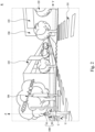
- Fig. 2 is a schematic diagram illustrating a user U operating the electronic device 100 as illustrated in Fig. 1 in accordance with some embodiments of the present disclosure.
- the user U is wearing an HMD device 10 on the head and holding tracking devices 20 on the hands.
- the HMD device 10 and the tracking devices 20 as illustrated in Fig. 2 represent the electronic device 100 as illustrated in Fig. 1 .
- the camera circuit 130 as illustrated in Fig. 1 obtains several environmental images corresponding to the real space R.
- the environmental images are the tracking scenes
- the processor 150 establishes a SLAM map including a coordinate system C in correspondence to the real space R according to several environmental images obtained by the camera circuit 130.
- the directions X, Y, and Z are the three axes of the coordinate system C.
- the processor 150 obtains a pose of the electronic device 100 within the coordinate system C of the SLAM map according to the features obtained from the environmental images captured by the camera circuit 130.
- the processor 150 tracks the pose of the electronic device 100 within the coordinate system C of the SLAM map.
- the coordinate system C of the SLAM map could be an augmented reality coordinate system, an extended reality coordinate system, or a mixed reality coordinate system.
- the pose of the electronic device 100 includes a position and a rotation angle.
- the real space R includes several common objects O1 to O6 that commonly exist outdoors, such as the sidewalks, trees, signs, streetlights, traffic lights, buildings, and so on. It should be noted that the common objects O1 to O6 as mentioned above are for illustrative purposes only, and more common objects may exist in the real space R.
- Fig. 3 is a flowchart illustrating a control method 300 in accordance with some embodiments of the present disclosure. It should be noted that the control method 300 can be applied to a device having a structure that is the same as or similar to the structured of the electronic device 100 shown in Fig. 1 . To simplify the description below, the embodiments shown in Fig. 1 will be used as an example to describe the control method 300 in accordance with some embodiments of the present disclosure. However, the present disclosure is not limited to the embodiments shown in Fig. 1 .
- control method 300 includes operations S310 to S370.
- a physical map and a database are stored in the memory 110 of the electronic device 100.
- the database includes several common object types.
- Each of the common object types includes several predefined common object images and common object 3D data.
- each of the predefined common object images corresponds to one of the common object 3D data.
- the common object types include a sidewalks type, a trees type, a signs type, a streetlights type, a traffic lights type, a buildings type, and so on.
- the streetlights type Take the streetlights type as an example.
- the streetlights type includes several different images of the streetlights and several 3D data (for example, 3D images or 3D models) of different street lights.
- the processor 150 obtains the GPS (global positioning system) position of the electronic device 100. According to the GPS position of the electronic device 100, the processor 150 obtains the physical map and the database corresponding to the GPS position. For example, in some embodiments, the processor 150 obtains the physical map within a certain range of the GPS position, and the processor 150 obtains the database with the common objects within the certain range of the GPS position.
- GPS global positioning system
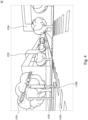
- Fig. 4 is a schematic diagram illustrating an environmental image EI captured by the camera circuit 130 while the electronic device 100 is operated in the real space R as illustrated in Fig. 2 in accordance with some embodiments of the present disclosure.
- the common object image CO1 is a common object image of a traffic light
- the common object image CO2 is a common object image of a streetlight
- the common object image CO3 is a common object image of a sidewalks
- the common object image CO4 and the common object image CO5 are common object images of buildings.
- operation S340 several common object images are classified and the regions of the common object images are obtained by the processor 150.
- the processor 150 compares the common object image CO1 to the several predefined common object images of the database, and the processor 150 chooses the common object image type including the predefined common object image most similar to the common object image CO1.
- the processor 150 decides that the streetlights type is the common object image type of the common object image CO1.
- the processor 150 obtains the region COR of the common object image CO1 in the environmental image EI, as illustrated in Fig. 4 .
- the processor 150 obtains the region COR with image detection algorithm.
- operation S350 several feature points are extracted from the environmental image EI.
- the processor 150 further emphasized the region COR of the common object image CO1 in the environmental image EI and the feature points within the region COR corresponding to the common object image CO1.
- operation S360 the feature points corresponding to the common object images are adjusted by the processor 150.
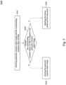
- Fig. 5 is a flow chart illustrating the operation S360 as illustrated in Fig. 3 in accordance with some embodiments of the present disclosure.
- operation S360 includes operations S361 to S364.
- the common object 3D data includes the geometric and visual properties of objects in three-dimensional space.
- operation S362 it is determined whether the corresponding common object 3D data is aligned to the particular common object image by the processor 150.
- the processor 150 adjusts the size and the position of the corresponding common object 3D data to align the corresponding common object 3D data to the particular common object image.
- the processor 150 further rotates the corresponding common object 3D data to align the corresponding common object 3D data to the particular common object image.
- operation S364 when the corresponding common object 3D data is successfully aligned to the particular common object image, operation S364 is performed.
- operation S363 is performed when the corresponding common object 3D data is not successfully aligned to the particular common object image.
- the deviation between the adjusted, rotated, and positioned corresponding common object 3D data and the particular common object image is smaller than a deviation threshold, it is determined that the corresponding common object 3D data is successfully aligned to the particular common object image.
- the particular common object image is aborted by the processor 150. That is, the particular common object image and the corresponding feature points are not emphasized when locating the pose of the electronic device 100 or when updating the SLAM map.
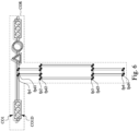
- Fig. 6 is a schematic diagram illustrating an example of operation S364 in accordance with some embodiments of the present disclosure.
- the common object image CO1 includes several feature points fp1 to fp4, and when the corresponding common object 3D data CO1D is aligned to the common object image CO1 within the environmental image EI, the corresponding common object 3D data CO1D includes the feature points fpd1 to fpd4.
- the processor 150 adjusts the feature points corresponding to the common object image CO1 of the environmental image EI by replacing the feature points fp1 to fp4 with the feature points fpd1 to fpd4. That is, when locating the pose of the electronic device 100 or when updating the SLAM map, the processor 150 takes the feature points fp1 to fp4 into consideration instead of the feature points fpd1 to fpd4.
- the feature points of the environmental image EI captured by the processor 150 are taken as the map points of the SLAM map.
- Each of the map points includes a coordinate value in the coordinate system C of the SLAM map.
- Each of the feature points may be converted into a map point.
- the conversion method between the map points and the feature points may be, for example, through the feature points and the coordinate values and the direction values of the images, that is, the environmental image, captured by the camera circuit 130 of the electronic device 100.
- all of the images captured by the camera circuit 130 of the electronic device 100 will be given a coordinate value and a direction value, and the feature points of the environmental image EI can be converted into map point coordinates through the coordinate value and the direction value of the environmental image EI.
- the environmental image EI of the past is stored in the SLAM map as a key frame, and the coordinate values and the direction values of the environmental image EI will be updated at the same time when the SLAM map is updated.
- the map points are correspondingly adjusted.
- Fig. 7 is a flow chart illustrating operation S370 as illustrated in Fig. 3 in accordance with some embodiments of the present disclosure. As illustrated in Fig. 7 , operation S370 includes operation S371 to S375.
- the environmental image EI with the feature points and the adjusted feature points in operation S360 as illustrated in Fig. 3 is taken as the current key frame in operation S370.
- Fig. 8 is a schematic diagram illustrating a physical map 800 in accordance with some embodiments of the present disclosure.
- the physical map 800 includes the positions of the streets, the buildings, the street blocks, etc., as illustrated in Fig. 8 . In some embodiments, the physical map 800 also includes relative distances between the streets, the buildings, the street blocks.
- Fig. 9 is a flow chart illustrating the operation S371 as illustrated in Fig. 7 in accordance with some embodiments of the present disclosure. As illustrated in Fig. 9 , operation S371 includes operations S371a to S371d.
- the processor 150 in Fig. 1 obtains the map point of the common object O5 as illustrated in Fig. 2 corresponding to the common object image CO5.
- the processor 150 in Fig. 1 obtains the map point of the common object O4 as illustrated in Fig. 2 corresponding to the common object image CO4.
- the center or the average of the feature points of the common object image is used to calculate the map point of the common object corresponding to the common object image.
- the physical object P1 is the common object O5 in Fig. 8
- the physical object P2 is the common object O4 in Fig. 8
- the physical map 800 records the physical distance between the physical object P1 and the physical object P2.
- the physical distance is the actual distance in the real space R.
- the processor 150 compares the physical distance between the physical object P1 and the physical object P2 to the distance between the map point of the common object O4 and the common object O5. When the deviation between the physical distance between the physical object P1 and the physical object P2 and the distance between the map point of the common object O4 and the map point of the common object O5 is smaller than a threshold value, it is determined that the physical distance between the physical object P1 and the physical object P2 fits the distance between the map point of the common object O4 and the map point of the common object O5.
- operation S371c it is determined that the environmental image is successfully mapped to the physical map. That is, the corresponding pose of the electronic device 100 can be found in the physical map according to the current key frame, and the current key frame is successfully mapped to the physical map.
- operation S371d it is determined that the environmental image is not successfully mapped to the physical map. That is, the corresponding pose of the electronic device 100 cannot be found in the physical map according to the current key frame, and the current key frame is not successfully mapped to the physical map.
- operation S372 it is determined whether the current key frame mapped to the physical map matches the current SLAM map. In some embodiments, the processor 150 determines whether the current key frame conforms to the nearby key frames (e.g. the previous key frame and/or the following key frame).
- the processor 150 determines that the current key frame matches the current SLAM map according to the physical map information of the current SLAM map.
- the current key frame is inserted into the SLAM map without the physical map information.
- the corresponding pose of the electronic device 100 cannot be found in the physical map or the pose corresponding to the current key frame in the physical map does not match the physical map information of the current SLAM map. That is, the current key frame is not mapped to the physical map or the current key frame does not matches the current SLAM map.
- the current key frame is only inserted into the SLAM map in the form of the feature points, with all real matched information ignored.
- the current key frame is inserted into the SLAM map and the SLAM module without the physical map information.
- the current key frame is inserted into the SLAM map with the physical map information.
- the corresponding pose of the electronic device 100 is successfully found in the physical map and the current key frame matches the physical map of the SLAM map. That is, the current key frame is mapped to the physical map and the current key frame matches the current SLAM map.
- the current key frame is inserted into the SLAM map and the SLAM module with the physical map information and the feature points.
- the SLAM map is updated.
- the processor 150 updates the SLAM map according to the inserted current key frame with/without the physical map information.
- the physical map information includes the GPS information, the physical positions and relative distances between the objects within the physical map or the SLAM map, etc. With the updated SLAM map, the pose of the electronic device 100 may be obtained more accurately.
- an electronic device a control method, and a non-transitory computer readable storage medium are implemented.
- pre-trained models may be employed to detect common object images in the environmental images and utilizing object discovery algorithms to search for the presence of expected common objects in the environmental images.
- object discovery algorithms to search for the presence of expected common objects in the environmental images.
- the actual dimensions of the common objects in the physical map are prepared in advance. For example, the actual width of a crosswalk, the types and sizes of tiles, the patterns and feature locations of business signs, the sizes of streetlights and traffic lights, the dimensions of directional signs, and so on.
- control method 300 no particular sequence is required unless otherwise specified. Moreover, the operations may also be performed simultaneously or the execution times thereof may at least partially overlap.
- control method 300 may be added to, replaced, and/or eliminated as appropriate, in accordance with various embodiments of the present disclosure.
- circuits either dedicated circuits, or general purpose circuits, which operate under the control of one or more processing circuits and coded instructions
- the functional blocks will typically include transistors or other circuit elements that are configured in such a way as to control the operation of the circuity in accordance with the functions and operations described herein.
Landscapes
- Engineering & Computer Science (AREA)
- Physics & Mathematics (AREA)
- General Physics & Mathematics (AREA)
- Theoretical Computer Science (AREA)
- Remote Sensing (AREA)
- Radar, Positioning & Navigation (AREA)
- Computer Vision & Pattern Recognition (AREA)
- Multimedia (AREA)
- Software Systems (AREA)
- Automation & Control Theory (AREA)
- Health & Medical Sciences (AREA)
- Artificial Intelligence (AREA)
- Computing Systems (AREA)
- Databases & Information Systems (AREA)
- Evolutionary Computation (AREA)
- General Health & Medical Sciences (AREA)
- Medical Informatics (AREA)
- Computer Graphics (AREA)
- Architecture (AREA)
- Computer Hardware Design (AREA)
- General Engineering & Computer Science (AREA)
- Processing Or Creating Images (AREA)
- User Interface Of Digital Computer (AREA)
- Length Measuring Devices By Optical Means (AREA)
Abstract
An electronic device is disclosed. The electronic device includes a memory, a camera circuit, and a processor. The memory is configured to store a physical map and a database. The database includes several predefined common object images corresponding several common object 3D data. The camera circuit is configured to capture an environmental image. The processor is configured to: obtain a first common object image from the environmental image; extract several feature points from the environmental image; adjust several first feature points of the feature points when a first common object 3D data of the several common object 3D data is aligned to the first common object image; and update the SLAM map according to the plurality of feature points of the environmental image.
Description
- The present application relates to an electronic device, a control method, and a non-transitory computer readable storage medium. More particularly, the present application relates to an electronic device, a control method, and a non-transitory computer readable storage medium with a SLAM (simultaneous localization and mapping) system.
- When using SLAM (Simultaneous Localization and Mapping) systems outdoors, there are often more challenging tracking conditions compared to indoor environments. These challenges include the presence of moving objects such as pedestrians and vehicles, as well as dynamic elements like trees and clouds, which exhibit high similarity but inherent variations. These tracking challenges are frequently encountered in outdoor scenes.
- Another difference between outdoor and indoor environments is the infinite expanse of the skyline. Outdoors, there are no end walls, which reduce the availability of trackable features. Instead, the sky and ground often occupy the tracking scene, both of which are challenging to track.
- Therefore, how to track the features of the outdoor environments and to locate the electronic device within the SLAM map precisely while operating the electronic device with the SLAM system outdoors is a problem to be solved.
- The disclosure provides an electronic device. The electronic device is configured to construct a SLAM map with a SLAM module. The electronic device includes a memory, a camera circuit, and a processor. The memory is configured to store a physical map and a database. The database includes several predefined common object images corresponding several
common object 3D data. The camera circuit is configured to capture an environmental image. The processor is coupled to the memory and the camera circuit. The processor is configured to: obtain a first common object image from the environmental image; extract several feature points from the environmental image; adjust several first feature points of the feature points when a firstcommon object 3D data of the severalcommon object 3D data is aligned to the first common object image; and update the SLAM map according to the plurality of feature points of the environmental image. - The disclosure provides a control method. The control method is suitable for an electronic device. The control method includes the following operations: storing a physical map and a database, in which the database includes several predefined common object images corresponding several
common object 3D data; capturing an environmental image; obtaining a first common object image from the environmental image,; extracting several feature points from the environmental image; adjusting several first feature points of the feature points when a firstcommon object 3D data of the severalcommon object 3D data is aligned to the first common object image; and updating a SLAM map constructed by the electronic device according to the plurality of feature points of the environmental image. - The disclosure provides a non-transitory computer readable storage medium with a computer program to execute aforesaid control method.
- It is to be understood that both the foregoing general description and the following detailed description are by examples and are intended to provide further explanation of the invention as claimed.
- Aspects of the present disclosure are best understood from the following detailed description when read with the accompanying figures. It is noted that, according to the standard practice in the industry, various features are not drawn to scale. In fact, the dimensions of the various features may be arbitrarily increased or reduced for clarity of discussion.
-
Fig. 1 is a schematic block diagram illustrating an electronic device in accordance with some embodiments of the present disclosure. -
Fig. 2 is a schematic diagram illustrating a user operating the electronic device as illustrated inFig. 1 in accordance with some embodiments of the present disclosure. -
Fig. 3 is a flowchart illustrating a control method in accordance with some embodiments of the present disclosure. -
Fig. 4 is a schematic diagram illustrating an environmental image captured by the camera circuit while the electronic device is operated in the real space as illustrated inFig. 2 in accordance with some embodiments of the present disclosure. -
Fig. 5 is a flow chart illustrating an operation as illustrated inFig. 3 in accordance with some embodiments of the present disclosure. -
Fig. 6 is a schematic diagram illustrating an example of an operation as illustrated inFig. 5 in accordance with some embodiments of the present disclosure. -
Fig. 7 is a flow chart illustrating an operation as illustrated inFig. 3 in accordance with some embodiments of the present disclosure. -
Fig. 8 is a schematic diagram illustrating a physical map in accordance with some embodiments of the present disclosure. -
Fig. 9 is a flow chart illustrating an operation as illustrated inFig. 7 in accordance with some embodiments of the present disclosure. - Reference will now be made in detail to the present embodiments of the disclosure, examples of which are illustrated in the accompanying drawings. Wherever possible, the same reference numbers are used in the drawings and the description to refer to the same or like parts.
- It will be understood that, in the description herein and throughout the claims that follow, although the terms "first," "second," etc. may be used to describe various elements, these elements should not be limited by these terms. These terms are only used to distinguish one element from another. For example, a first element could be termed a second element, and, similarly, a second element could be termed a first element, without departing from the scope of the embodiments.
- It will be understood that, in the description herein and throughout the claims that follow, the terms "comprise" or "comprising," "include" or "including," "have" or "having," "contain" or "containing" and the like used herein are to be understood to be open-ended, i.e., to mean including but not limited to.
- It will be understood that, in the description herein and throughout the claims that follow, the phrase "and/or" includes any and all combinations of one or more of the associated listed items.
- Reference is made to
Fig. 1. Fig. 1 is a schematic block diagram illustrating anelectronic device 100 in accordance with some embodiments of the present disclosure. As illustrated inFig. 1 , theelectronic device 100 includes amemory 110, acamera circuit 130, and aprocessor 150. In the connection relationship, thememory 110 is coupled to theprocessor 150, and theprocessor 150 is coupled to thecamera circuit 130. - It should be noted that the
electronic device 100 inFig. 1 is for illustrative purposes only, and the embodiments of the present disclosure are not limited thereto. For example, in some embodiments, theelectronic device 100 includes several camera circuits. - One or more programs are stored in the
memory 110 and are configured to be executed by theprocessor 150, in order to perform a control method. - In some embodiments, the
electronic device 100 may be an HMD (head-mounted display) device, a tracking device, or any other device with self-tracking function. The HMD device may be worn on the head of a user. - In some embodiments, the
memory 110 stores a SLAM (Simultaneous localization and mapping) module. Theelectronic device 100 may be configured to process the SLAM module. The SLAM module includes functions such as image capturing, features extracting from the image, and localizing according to the extracted features. In some embodiments, the SLAM module includes a SLAM algorithm, in which theprocessor 150 accesses and processes the SLAM module so as to generate a SLAM map according to the extracted features and to localize theelectronic device 100 within the SLAM map according to the images captured by thecamera circuit 130 of theelectronic device 100. - Specifically, in some embodiments, the
electronic device 100 may be applied in a virtual reality (VR)/mixed reality (MR)/augmented reality (AR) system. For example, theelectronic device 100 may be realized by a standalone head mounted display device (HMD) or VIVE HMD. - In some embodiments, the
processor 150 can be realized by, for example, one or more processing circuits, such as central processing circuits and/or micro processing circuits but are not limited in this regard. In some embodiments, thememory 110 includes one or more memory devices, each of which includes, or a plurality of which collectively include a computer readable storage medium. The non-transitory computer readable storage medium may include a read-only memory (ROM), a flash memory, a floppy disk, a hard disk, an optical disc, a flash disk, a flash drive, a tape, a database accessible from a network, and/or any storage medium with the same functionality that can be contemplated by persons of ordinary skill in the art to which this disclosure pertains. - In some embodiments, the
camera circuit 130 may be a camera with image capturing functions. - In some embodiments, the
electronic device 100 includes other circuits such as a display circuit and an I/O circuit. In some embodiments, the display circuit covers a field of view of the user and shows a virtual image at the field of view of the user. - Reference is made to
Fig. 2 together.Fig. 2 is a schematic diagram illustrating a user U operating theelectronic device 100 as illustrated inFig. 1 in accordance with some embodiments of the present disclosure. - As illustrated in
Fig. 2 , the user U is wearing anHMD device 10 on the head and holdingtracking devices 20 on the hands. In some embodiments, theHMD device 10 and thetracking devices 20 as illustrated inFig. 2 represent theelectronic device 100 as illustrated inFig. 1 . - In some embodiments, when the
electronic device 100 is operating in the real space R, thecamera circuit 130 as illustrated inFig. 1 obtains several environmental images corresponding to the real space R. In some embodiments, the environmental images are the tracking scenes, and theprocessor 150 establishes a SLAM map including a coordinate system C in correspondence to the real space R according to several environmental images obtained by thecamera circuit 130. The directions X, Y, and Z are the three axes of the coordinate system C. In some embodiments, theprocessor 150 obtains a pose of theelectronic device 100 within the coordinate system C of the SLAM map according to the features obtained from the environmental images captured by thecamera circuit 130. - When the
electronic device 100 moves in the real space R, theprocessor 150 tracks the pose of theelectronic device 100 within the coordinate system C of the SLAM map. - In other embodiments, the coordinate system C of the SLAM map could be an augmented reality coordinate system, an extended reality coordinate system, or a mixed reality coordinate system. In some embodiments, the pose of the
electronic device 100 includes a position and a rotation angle. - As illustrated in
Fig. 2 . In some embodiments, the real space R includes several common objects O1 to O6 that commonly exist outdoors, such as the sidewalks, trees, signs, streetlights, traffic lights, buildings, and so on. It should be noted that the common objects O1 to O6 as mentioned above are for illustrative purposes only, and more common objects may exist in the real space R. - Reference is made to
Fig. 3 . For better understanding of the present disclosure, the detailed operation of theelectronic device 100 as illustrated inFig. 1 will be discussed in accompanying the embodiments shown inFig. 3. Fig. 3 is a flowchart illustrating acontrol method 300 in accordance with some embodiments of the present disclosure. It should be noted that thecontrol method 300 can be applied to a device having a structure that is the same as or similar to the structured of theelectronic device 100 shown inFig. 1 . To simplify the description below, the embodiments shown inFig. 1 will be used as an example to describe thecontrol method 300 in accordance with some embodiments of the present disclosure. However, the present disclosure is not limited to the embodiments shown inFig. 1 . - As shown in
Fig. 3 , thecontrol method 300 includes operations S310 to S370. - In operation S310, a physical map and a database are stored in the
memory 110 of theelectronic device 100. In some embodiments, the database includes several common object types. Each of the common object types includes several predefined common object images andcommon object 3D data. In some embodiments, each of the predefined common object images corresponds to one of thecommon object 3D data. - For example, in some embodiments, the common object types include a sidewalks type, a trees type, a signs type, a streetlights type, a traffic lights type, a buildings type, and so on. Take the streetlights type as an example. In some embodiments, the streetlights type includes several different images of the streetlights and several 3D data (for example, 3D images or 3D models) of different street lights.
- In some embodiments, the
processor 150 obtains the GPS (global positioning system) position of theelectronic device 100. According to the GPS position of theelectronic device 100, theprocessor 150 obtains the physical map and the database corresponding to the GPS position. For example, in some embodiments, theprocessor 150 obtains the physical map within a certain range of the GPS position, and theprocessor 150 obtains the database with the common objects within the certain range of the GPS position. - In operation S320, an environmental image is captured by the
camera circuit 130. Reference is made toFig. 4 together.Fig. 4 is a schematic diagram illustrating an environmental image EI captured by thecamera circuit 130 while theelectronic device 100 is operated in the real space R as illustrated inFig. 2 in accordance with some embodiments of the present disclosure. - In operation S330, several common object images are obtained from the environmental image EI by the
processor 150. Reference is made toFig. 4 together. According to the environmental image EI, theprocessor 150 obtains common object images CO1 to CO5. Each of the common object images CO1 to CO5 corresponds to one of the common objects in the real space R as illustrated inFig. 2 . - In
Fig. 4 , the common object image CO1 is a common object image of a traffic light, the common object image CO2 is a common object image of a streetlight, the common object image CO3 is a common object image of a sidewalks, the common object image CO4 and the common object image CO5 are common object images of buildings. - In operation S340, several common object images are classified and the regions of the common object images are obtained by the
processor 150. Reference is made toFig. 4 together. Take the common object image CO1 as an example. In operation S340, theprocessor 150 compares the common object image CO1 to the several predefined common object images of the database, and theprocessor 150 chooses the common object image type including the predefined common object image most similar to the common object image CO1. For example, in an embodiment, theprocessor 150 decides that the streetlights type is the common object image type of the common object image CO1. - Moreover, in operation S340, the
processor 150 obtains the region COR of the common object image CO1 in the environmental image EI, as illustrated inFig. 4 . In some embodiments, theprocessor 150 obtains the region COR with image detection algorithm. - In operation S350, several feature points are extracted from the environmental image EI. In some embodiments, in operation S350, the
processor 150 further emphasized the region COR of the common object image CO1 in the environmental image EI and the feature points within the region COR corresponding to the common object image CO1. - In operation S360, the feature points corresponding to the common object images are adjusted by the
processor 150. Reference is made toFig. 5 together.Fig. 5 is a flow chart illustrating the operation S360 as illustrated inFig. 3 in accordance with some embodiments of the present disclosure. As illustrated inFig. 5 , operation S360 includes operations S361 to S364. - In operation S361, the particular common object image and the corresponding
common object 3D data are retrieved by theprocessor 150. Reference is made toFig. 4 together. - For example, in operation S361, common object image CO1 is taken as the particular common object image. The
processor 150 then retrieves the correspondingcommon object 3D data which corresponds to the predefined common object image which is most similar to the common object image CO1 from the database. - In some embodiments, the
common object 3D data includes the geometric and visual properties of objects in three-dimensional space. - In operation S362, it is determined whether the corresponding
common object 3D data is aligned to the particular common object image by theprocessor 150. In some embodiments, theprocessor 150 adjusts the size and the position of the correspondingcommon object 3D data to align the correspondingcommon object 3D data to the particular common object image. In some embodiments, theprocessor 150 further rotates the correspondingcommon object 3D data to align the correspondingcommon object 3D data to the particular common object image. - In some embodiments, when the corresponding
common object 3D data is successfully aligned to the particular common object image, operation S364 is performed. When the correspondingcommon object 3D data is not successfully aligned to the particular common object image, operation S363 is performed. - In some embodiments, when the deviation between the adjusted, rotated, and positioned corresponding
common object 3D data and the particular common object image is smaller than a deviation threshold, it is determined that the correspondingcommon object 3D data is successfully aligned to the particular common object image. - In operation S363, the particular common object image is aborted by the
processor 150. That is, the particular common object image and the corresponding feature points are not emphasized when locating the pose of theelectronic device 100 or when updating the SLAM map. - In operation S364, the feature points and the map points are adjusted by the
processor 150. Reference is made toFig. 6 together.Fig. 6 is a schematic diagram illustrating an example of operation S364 in accordance with some embodiments of the present disclosure. As illustrated inFig. 6 , within the region COR corresponding to the common object image CO1, the common object image CO1 includes several feature points fp1 to fp4, and when the correspondingcommon object 3D data CO1D is aligned to the common object image CO1 within the environmental image EI, the correspondingcommon object 3D data CO1D includes the feature points fpd1 to fpd4. - In some embodiments, in operation S364, the
processor 150 adjusts the feature points corresponding to the common object image CO1 of the environmental image EI by replacing the feature points fp1 to fp4 with the feature points fpd1 to fpd4. That is, when locating the pose of theelectronic device 100 or when updating the SLAM map, theprocessor 150 takes the feature points fp1 to fp4 into consideration instead of the feature points fpd1 to fpd4. - In some embodiments, the feature points of the environmental image EI captured by the
processor 150 are taken as the map points of the SLAM map. Each of the map points includes a coordinate value in the coordinate system C of the SLAM map. Each of the feature points may be converted into a map point. - The conversion method between the map points and the feature points may be, for example, through the feature points and the coordinate values and the direction values of the images, that is, the environmental image, captured by the
camera circuit 130 of theelectronic device 100. In the SLAM system, all of the images captured by thecamera circuit 130 of theelectronic device 100 will be given a coordinate value and a direction value, and the feature points of the environmental image EI can be converted into map point coordinates through the coordinate value and the direction value of the environmental image EI. - The environmental image EI of the past is stored in the SLAM map as a key frame, and the coordinate values and the direction values of the environmental image EI will be updated at the same time when the SLAM map is updated.
- In some embodiments, when the feature points are adjusted in operation S364, the map points are correspondingly adjusted.
- Reference is made to
Fig. 3 again. In operation S370, the SLAM map is updated with the physical map and the feature points by theprocessor 150. Reference is made toFig. 7 together.Fig. 7 is a flow chart illustrating operation S370 as illustrated inFig. 3 in accordance with some embodiments of the present disclosure. As illustrated inFig. 7 , operation S370 includes operation S371 to S375. - In some embodiments, the environmental image EI with the feature points and the adjusted feature points in operation S360 as illustrated in
Fig. 3 is taken as the current key frame in operation S370. - In operation S371, it is determined whether the current key frame is successfully mapped to the physical map. Reference is made to
Fig. 8. Fig. 8 is a schematic diagram illustrating aphysical map 800 in accordance with some embodiments of the present disclosure. - In some embodiments, the
physical map 800 includes the positions of the streets, the buildings, the street blocks, etc., as illustrated inFig. 8 . In some embodiments, thephysical map 800 also includes relative distances between the streets, the buildings, the street blocks. - Reference is made to
Fig. 9 together.Fig. 9 is a flow chart illustrating the operation S371 as illustrated inFig. 7 in accordance with some embodiments of the present disclosure. As illustrated inFig. 9 , operation S371 includes operations S371a to S371d. - In operation S371a, a first map point of the first common object and a second map point of the second common object within the SLAM map are obtained.
- Reference is made to
Fig. 2 andFig. 4 together. According to the feature points of the common object image CO5 inFig. 4 , theprocessor 150 inFig. 1 obtains the map point of the common object O5 as illustrated inFig. 2 corresponding to the common object image CO5. Similarly, according to the feature points of the common object image CO4 inFig. 4 , theprocessor 150 inFig. 1 obtains the map point of the common object O4 as illustrated inFig. 2 corresponding to the common object image CO4. - In some embodiments, the center or the average of the feature points of the common object image is used to calculate the map point of the common object corresponding to the common object image.
- In operation S371b, it is determined whether a distance between the first map point and the second map point fits a physical distance between a first physical object corresponding to the first common object and a second physical object corresponding to the second common object within the physical map.
- Reference is made to
Fig. 8 together. InFig. 8 , the physical object P1 is the common object O5 inFig. 8 , and the physical object P2 is the common object O4 inFig. 8 . In some embodiments, thephysical map 800 records the physical distance between the physical object P1 and the physical object P2. In some embodiments, the physical distance is the actual distance in the real space R. - In some embodiments, the
processor 150 compares the physical distance between the physical object P1 and the physical object P2 to the distance between the map point of the common object O4 and the common object O5. When the deviation between the physical distance between the physical object P1 and the physical object P2 and the distance between the map point of the common object O4 and the map point of the common object O5 is smaller than a threshold value, it is determined that the physical distance between the physical object P1 and the physical object P2 fits the distance between the map point of the common object O4 and the map point of the common object O5. - In operation S371c, it is determined that the environmental image is successfully mapped to the physical map. That is, the corresponding pose of the
electronic device 100 can be found in the physical map according to the current key frame, and the current key frame is successfully mapped to the physical map. - On the other hand, in operation S371d, it is determined that the environmental image is not successfully mapped to the physical map. That is, the corresponding pose of the
electronic device 100 cannot be found in the physical map according to the current key frame, and the current key frame is not successfully mapped to the physical map. - Reference is made to
Fig. 7 again. In operation S372, it is determined whether the current key frame mapped to the physical map matches the current SLAM map. In some embodiments, theprocessor 150 determines whether the current key frame conforms to the nearby key frames (e.g. the previous key frame and/or the following key frame). - When the current key frame conflicts with the nearby key frames, it is determined that the current key frame mapped to the physical map does not match the current SLAM map, and operation S373 is performed. On the other hand, when the current key frame conforms to the nearby key frames, it is determined that the current key frame mapped to the physical map matches the current SLAM map, and operation S374 is performed.
- In some embodiments, in operation S372, the
processor 150 determines that the current key frame matches the current SLAM map according to the physical map information of the current SLAM map. - In operation S373, the current key frame is inserted into the SLAM map without the physical map information. In some embodiments, in operation S373, according to the current key frame, the corresponding pose of the
electronic device 100 cannot be found in the physical map or the pose corresponding to the current key frame in the physical map does not match the physical map information of the current SLAM map. That is, the current key frame is not mapped to the physical map or the current key frame does not matches the current SLAM map. Then, in operation S373, the current key frame is only inserted into the SLAM map in the form of the feature points, with all real matched information ignored. The current key frame is inserted into the SLAM map and the SLAM module without the physical map information. - In operation S374, the current key frame is inserted into the SLAM map with the physical map information. In some embodiments, in operation S374, according to the current key frame, the corresponding pose of the
electronic device 100 is successfully found in the physical map and the current key frame matches the physical map of the SLAM map. That is, the current key frame is mapped to the physical map and the current key frame matches the current SLAM map. Then, in operation S374, the current key frame is inserted into the SLAM map and the SLAM module with the physical map information and the feature points. - In operation S375, the SLAM map is updated. In some embodiments, in operation S375, the
processor 150 updates the SLAM map according to the inserted current key frame with/without the physical map information. In some embodiments, the physical map information includes the GPS information, the physical positions and relative distances between the objects within the physical map or the SLAM map, etc. With the updated SLAM map, the pose of theelectronic device 100 may be obtained more accurately. - Through the operations of various embodiments described above, an electronic device, a control method, and a non-transitory computer readable storage medium are implemented. According to the predefined common object images such as sidewalks, crosswalks, business signs, streetlights, traffic lights, and more, stored in the database of the memory, pre-trained models may be employed to detect common object images in the environmental images and utilizing object discovery algorithms to search for the presence of expected common objects in the environmental images. By aligning the corresponding
common object 3D data to the common object images in the environmental image, the accuracy of the feature points in the environmental image may be increased, and the accuracy of the tracking of the pose of the electronic device within the SLAM map may be increased. - Furthermore, in the embodiments of the present disclosure, the actual dimensions of the common objects in the physical map are prepared in advance. For example, the actual width of a crosswalk, the types and sizes of tiles, the patterns and feature locations of business signs, the sizes of streetlights and traffic lights, the dimensions of directional signs, and so on. By mapping the environmental image to the physical map according to the common objects, the accuracy of the pose of the electronic device within the SLAM map is further increased.
- The advantage of tracking such predefined common objects lies in the fact that these common objects often have a long-term presence, are common in the outdoor environment of the area, and their predefined dimensions contribute to the accuracy of SLAM map points.
- It should be noted that in the operations of the
abovementioned control method 300, no particular sequence is required unless otherwise specified. Moreover, the operations may also be performed simultaneously or the execution times thereof may at least partially overlap. - Furthermore, the operations of the
control method 300 may be added to, replaced, and/or eliminated as appropriate, in accordance with various embodiments of the present disclosure. - Various functional components or blocks have been described herein. As will be appreciated by persons skilled in the art, the functional blocks will preferably be implemented through circuits (either dedicated circuits, or general purpose circuits, which operate under the control of one or more processing circuits and coded instructions), which will typically include transistors or other circuit elements that are configured in such a way as to control the operation of the circuity in accordance with the functions and operations described herein.
- Although the present disclosure has been described in considerable detail with reference to certain embodiments thereof, other embodiments are possible. Therefore, the scope of the appended claims should not be limited to the description of the embodiments contained herein.
- It will be apparent to those skilled in the art that various modifications and variations can be made to the structured of the present invention without departing from the scope or spirit of the invention. In view of the foregoing, it is intended that the present invention cover modifications and variations of this invention provided they fall within the scope of the following claims.
Claims (15)
- An electronic device, configured to construct a SLAM map with a SLAM module, comprising:a memory, configured to store a physical map and a database, wherein the database comprises a plurality of predefined common object images corresponding a plurality of common object 3D data;a camera circuit, configured to capture an environmental image; anda processor, coupled to the memory and the camera circuit, configured to:obtain a first common object image from the environmental image;extract a plurality of feature points from the environmental image;adjust a plurality of first feature points of the feature points when a first common object 3D data of the plurality of common object 3D data is aligned to the first common object image; andupdate the SLAM map according to the plurality of feature points of the environmental image.
- The electronic device of claim 1, wherein the first common object image matches a first predefined common object image of the plurality of predefined common object images, the first common object 3D data corresponds to the first predefined common object image, and the plurality of first feature points corresponds to the first common object image.
- The electronic device of claim 1, wherein the processor is further configured to:obtain a GPS position of the electronic device; andobtain the physical map and the database according to the GPS position.
- The electronic device of claim 1, wherein the database comprises a plurality of common object types, the processor is further configured to:classify the first common object image into one of the plurality of common object types; andobtain and emphasize a region of the first common object image within the environmental image.
- The electronic device of claim 1, wherein the processor is further configured to:
abort the first common object image when the first common object 3D data is not aligned to the first common object image. - The electronic device of claim 1, wherein the processor is further configured to:adjust a size and a location of the first common object 3D data to align the first common object 3D data to the first common object image;obtain a plurality of second feature points according to the first common object 3D data when the first common object 3D data is aligned to the first common object image; andreplace the plurality of first feature points with the plurality of second feature points.
- The electronic device of claim 1, wherein the processor is further configured to:
update the SLAM map with a physical map information of the physical map when the environmental image is mapped to the physical map and the environmental image matches the SLAM map. - The electronic device of claim 7, wherein the environmental image further comprises a second common object image corresponding a second common object, wherein the first common object image corresponds to a first common object, wherein the processor is further configured to:obtain a first map point of the first common object and a second map point of the second common object within the SLAM map;determine whether a distance between the first map point and the second map point fits a physical distance between a first physical object corresponding to the first common object and a second physical object corresponding to the second common object within the physical map; anddetermine that the environmental image is mapped to the physical map when the distance fits the physical distance.
- A control method, suitable for an electronic device, comprising:storing a physical map and a database, wherein the database comprises a plurality of predefined common object images corresponding a plurality of common object 3D data;capturing an environmental image;obtaining a first common object image from the environmental image;extracting a plurality of feature points from the environmental image;adjusting a plurality of first feature points of the feature points when a first common object 3D data of the plurality of common object 3D data is aligned to the first common object image; andupdating a SLAM map constructed by the electronic device according to the plurality of feature points of the environmental image.
- The control method of claim 9, wherein the first common object image matches a first predefined common object image of the plurality of predefined common object images, the first common object 3D data corresponds to the first predefined common object image, and the plurality of first feature points corresponds to the first common object image.
- The control method of claim 9, further comprising:obtaining a GPS position of the electronic device; andobtaining the physical map and the database according to the GPS position.
- The control method of claim 9, wherein the database comprises a plurality of common object types, wherein the control method further comprising:classifying the first common object image into one of the plurality of common object types; andobtaining and emphasizing a region of the first common object image within the environmental image.
- The control method of claim 9, further comprising:
aborting the first common object image when the first common object 3D data is not aligned to the first common object image. - The control method of claim 9, wherein the operation of adjusting the plurality of first feature points of the plurality of feature points when the first common object 3D data of the plurality of common object 3D data is aligned to the first common object image of the environmental image comprising:adjusting a size and a location of the first common object 3D data to align the first common object 3D data to the first common object image;obtaining a plurality of second feature points according to the first common object 3D data when the first common object 3D data is aligned to the first common object image;replacing the plurality of first feature points with the plurality of second feature points; andupdating the SLAM map with a physical map information of the physical map when the environmental image is mapped to the physical map and the environmental image matches the SLAM map.
- A non-transitory computer readable storage medium, wherein the non-transitory computer readable storage medium comprises one or more computer programs stored therein, and the one or more computer programs can be executed by one or more processors so as to be configured to operate a control method, wherein the control method comprises:storing a physical map and a database, wherein the database comprises a plurality of predefined common object images corresponding a plurality of common object 3D data;capturing an environmental image;obtaining a first common object image from the environmental image;extracting a plurality of feature points from the environmental image;adjusting a plurality of first feature points of the feature points when a first common object 3D data of the plurality of common object 3D data is aligned to the first common object image,; andupdating a SLAM map according to the plurality of feature points of the environmental image.
Applications Claiming Priority (2)
| Application Number | Priority Date | Filing Date | Title |
|---|---|---|---|
| US202363598915P | 2023-11-14 | 2023-11-14 | |
| US202363598914P | 2023-11-14 | 2023-11-14 |
Publications (1)
| Publication Number | Publication Date |
|---|---|
| EP4556856A1 true EP4556856A1 (en) | 2025-05-21 |
Family
ID=93521581
Family Applications (1)
| Application Number | Title | Priority Date | Filing Date |
|---|---|---|---|
| EP24212811.4A Pending EP4556856A1 (en) | 2023-11-14 | 2024-11-13 | Electronic device, control method, and non-transitory computer readable storage medium |
Country Status (4)
| Country | Link |
|---|---|
| US (1) | US20250157067A1 (en) |
| EP (1) | EP4556856A1 (en) |
| CN (1) | CN120008579A (en) |
| TW (1) | TWI906030B (en) |
Citations (2)
| Publication number | Priority date | Publication date | Assignee | Title |
|---|---|---|---|---|
| US20140323148A1 (en) * | 2013-04-30 | 2014-10-30 | Qualcomm Incorporated | Wide area localization from slam maps |
| US20230129620A1 (en) * | 2016-12-09 | 2023-04-27 | Tomtom Global Content B.V. | Method and System for Video-Based Positioning and Mapping |
Family Cites Families (7)
| Publication number | Priority date | Publication date | Assignee | Title |
|---|---|---|---|---|
| US10445895B2 (en) * | 2014-11-21 | 2019-10-15 | Apple Inc. | Method and system for determining spatial coordinates of a 3D reconstruction of at least part of a real object at absolute spatial scale |
| US10989542B2 (en) * | 2016-03-11 | 2021-04-27 | Kaarta, Inc. | Aligning measured signal data with slam localization data and uses thereof |
| CN112785715B (en) * | 2019-11-08 | 2024-06-25 | 华为技术有限公司 | Virtual object display method and electronic device |
| AU2020409014A1 (en) * | 2019-12-20 | 2022-08-18 | Niantic Spatial, Inc. | Merging local maps from mapping devices |
| CN111161347B (en) * | 2020-04-01 | 2020-09-29 | 亮风台(上海)信息科技有限公司 | Method and equipment for initializing SLAM |
| CN111311684B (en) * | 2020-04-01 | 2021-02-05 | 亮风台(上海)信息科技有限公司 | Method and equipment for initializing SLAM |
| US12399501B2 (en) * | 2020-12-10 | 2025-08-26 | AI Incorporated | Method of lightweight simultaneous localization and mapping performed on a real-time computing and battery operated wheeled device |
-
2024
- 2024-11-12 TW TW113143434A patent/TWI906030B/en active
- 2024-11-12 CN CN202411605094.5A patent/CN120008579A/en active Pending
- 2024-11-12 US US18/943,976 patent/US20250157067A1/en active Pending
- 2024-11-13 EP EP24212811.4A patent/EP4556856A1/en active Pending
Patent Citations (2)
| Publication number | Priority date | Publication date | Assignee | Title |
|---|---|---|---|---|
| US20140323148A1 (en) * | 2013-04-30 | 2014-10-30 | Qualcomm Incorporated | Wide area localization from slam maps |
| US20230129620A1 (en) * | 2016-12-09 | 2023-04-27 | Tomtom Global Content B.V. | Method and System for Video-Based Positioning and Mapping |
Also Published As
| Publication number | Publication date |
|---|---|
| US20250157067A1 (en) | 2025-05-15 |
| TW202519830A (en) | 2025-05-16 |
| CN120008579A (en) | 2025-05-16 |
| TWI906030B (en) | 2025-11-21 |
Similar Documents
| Publication | Publication Date | Title |
|---|---|---|
| US20260085946A1 (en) | Method and system for video-based positioning and mapping | |
| CN107967457B (en) | A method and system for location recognition and relative positioning that adapts to changes in visual features | |
| US20220114797A1 (en) | Method for detecting objects and localizing a mobile computing device within an augmented reality experience | |
| US9400941B2 (en) | Method of matching image features with reference features | |
| Ventura et al. | Global localization from monocular slam on a mobile phone | |
| US8989483B2 (en) | Method and apparatus for inferring the geographic location of captured scene depictions | |
| Ramalingam et al. | Skyline2gps: Localization in urban canyons using omni-skylines | |
| CN115035260A (en) | Indoor mobile robot three-dimensional semantic map construction method | |
| Li et al. | TextSLAM: Visual SLAM with semantic planar text features | |
| CN109584302B (en) | Camera pose optimization method, device, electronic equipment and computer-readable medium | |
| US20150138310A1 (en) | Automatic scene parsing | |
| Gao et al. | Ground and aerial meta-data integration for localization and reconstruction: A review | |
| CN110794955A (en) | Positioning tracking method, device, terminal device and computer-readable storage medium | |
| CN108776976B (en) | A method, system and storage medium for simultaneous positioning and mapping | |
| EP4502950A1 (en) | Visual localization method and related apparatus | |
| CN114969221A (en) | Method for updating map and related equipment | |
| Höllerer et al. | “Anywhere augmentation”: Towards mobile augmented reality in unprepared environments | |
| KR20010055957A (en) | Image Registration Method Using 3D Tracker And Computer Vision For Augmented Reality | |
| WO2021250850A1 (en) | Training apparatus, control method, and non-transitory computer-readable storage medium | |
| CN113570535B (en) | Visual positioning method, and related device and equipment | |
| Schall et al. | 3D tracking in unknown environments using on-line keypoint learning for mobile augmented reality | |
| US20250157067A1 (en) | Electronic device, control method, and non-transitory computer readable storage medium | |
| CN114911985A (en) | Wartime field intelligent rescue system | |
| CN114550172A (en) | Electronic device positioning method, apparatus and computer readable storage medium | |
| CN116337068A (en) | Method and system for synchronous semantic positioning and mapping of robots based on humanoid thinking |
Legal Events
| Date | Code | Title | Description |
|---|---|---|---|
| PUAI | Public reference made under article 153(3) epc to a published international application that has entered the european phase |
Free format text: ORIGINAL CODE: 0009012 |
|
| STAA | Information on the status of an ep patent application or granted ep patent |
Free format text: STATUS: EXAMINATION IS IN PROGRESS |
|
| 17P | Request for examination filed |
Effective date: 20241113 |
|
| AK | Designated contracting states |
Kind code of ref document: A1 Designated state(s): AL AT BE BG CH CY CZ DE DK EE ES FI FR GB GR HR HU IE IS IT LI LT LU LV MC ME MK MT NL NO PL PT RO RS SE SI SK SM TR |