EP4556840A1 - Plate heat exchange module - Google Patents
Plate heat exchange module Download PDFInfo
- Publication number
- EP4556840A1 EP4556840A1 EP24020330.7A EP24020330A EP4556840A1 EP 4556840 A1 EP4556840 A1 EP 4556840A1 EP 24020330 A EP24020330 A EP 24020330A EP 4556840 A1 EP4556840 A1 EP 4556840A1
- Authority
- EP
- European Patent Office
- Prior art keywords
- turbulising
- elements
- plate
- module according
- plates
- Prior art date
- Legal status (The legal status is an assumption and is not a legal conclusion. Google has not performed a legal analysis and makes no representation as to the accuracy of the status listed.)
- Pending
Links
Images


Classifications
-
- F—MECHANICAL ENGINEERING; LIGHTING; HEATING; WEAPONS; BLASTING
- F28—HEAT EXCHANGE IN GENERAL
- F28D—HEAT-EXCHANGE APPARATUS, NOT PROVIDED FOR IN ANOTHER SUBCLASS, IN WHICH THE HEAT-EXCHANGE MEDIA DO NOT COME INTO DIRECT CONTACT
- F28D9/00—Heat-exchange apparatus having stationary plate-like or laminated conduit assemblies for both heat-exchange media, the media being in contact with different sides of a conduit wall
- F28D9/0031—Heat-exchange apparatus having stationary plate-like or laminated conduit assemblies for both heat-exchange media, the media being in contact with different sides of a conduit wall the conduits for one heat-exchange medium being formed by paired plates touching each other
- F28D9/0043—Heat-exchange apparatus having stationary plate-like or laminated conduit assemblies for both heat-exchange media, the media being in contact with different sides of a conduit wall the conduits for one heat-exchange medium being formed by paired plates touching each other the plates having openings therein for circulation of at least one heat-exchange medium from one conduit to another
- F28D9/005—Heat-exchange apparatus having stationary plate-like or laminated conduit assemblies for both heat-exchange media, the media being in contact with different sides of a conduit wall the conduits for one heat-exchange medium being formed by paired plates touching each other the plates having openings therein for circulation of at least one heat-exchange medium from one conduit to another the plates having openings therein for both heat-exchange media
-
- F—MECHANICAL ENGINEERING; LIGHTING; HEATING; WEAPONS; BLASTING
- F28—HEAT EXCHANGE IN GENERAL
- F28F—DETAILS OF HEAT-EXCHANGE AND HEAT-TRANSFER APPARATUS, OF GENERAL APPLICATION
- F28F3/00—Plate-like or laminated elements; Assemblies of plate-like or laminated elements
- F28F3/02—Elements or assemblies thereof with means for increasing heat-transfer area, e.g. with fins, with recesses, with corrugations
- F28F3/022—Elements or assemblies thereof with means for increasing heat-transfer area, e.g. with fins, with recesses, with corrugations the means being wires or pins
-
- F—MECHANICAL ENGINEERING; LIGHTING; HEATING; WEAPONS; BLASTING
- F28—HEAT EXCHANGE IN GENERAL
- F28D—HEAT-EXCHANGE APPARATUS, NOT PROVIDED FOR IN ANOTHER SUBCLASS, IN WHICH THE HEAT-EXCHANGE MEDIA DO NOT COME INTO DIRECT CONTACT
- F28D9/00—Heat-exchange apparatus having stationary plate-like or laminated conduit assemblies for both heat-exchange media, the media being in contact with different sides of a conduit wall
- F28D9/0062—Heat-exchange apparatus having stationary plate-like or laminated conduit assemblies for both heat-exchange media, the media being in contact with different sides of a conduit wall the conduits for one heat-exchange medium being formed by spaced plates with inserted elements
- F28D9/0075—Heat-exchange apparatus having stationary plate-like or laminated conduit assemblies for both heat-exchange media, the media being in contact with different sides of a conduit wall the conduits for one heat-exchange medium being formed by spaced plates with inserted elements the plates having openings therein for circulation of the heat-exchange medium from one conduit to another
-
- F—MECHANICAL ENGINEERING; LIGHTING; HEATING; WEAPONS; BLASTING
- F28—HEAT EXCHANGE IN GENERAL
- F28F—DETAILS OF HEAT-EXCHANGE AND HEAT-TRANSFER APPARATUS, OF GENERAL APPLICATION
- F28F13/00—Arrangements for modifying heat-transfer, e.g. increasing, decreasing
- F28F13/06—Arrangements for modifying heat-transfer, e.g. increasing, decreasing by affecting the pattern of flow of the heat-exchange media
- F28F13/08—Arrangements for modifying heat-transfer, e.g. increasing, decreasing by affecting the pattern of flow of the heat-exchange media by varying the cross-section of the flow channels
-
- F—MECHANICAL ENGINEERING; LIGHTING; HEATING; WEAPONS; BLASTING
- F28—HEAT EXCHANGE IN GENERAL
- F28F—DETAILS OF HEAT-EXCHANGE AND HEAT-TRANSFER APPARATUS, OF GENERAL APPLICATION
- F28F19/00—Preventing the formation of deposits or corrosion, e.g. by using filters or scrapers
-
- F—MECHANICAL ENGINEERING; LIGHTING; HEATING; WEAPONS; BLASTING
- F28—HEAT EXCHANGE IN GENERAL
- F28F—DETAILS OF HEAT-EXCHANGE AND HEAT-TRANSFER APPARATUS, OF GENERAL APPLICATION
- F28F3/00—Plate-like or laminated elements; Assemblies of plate-like or laminated elements
- F28F3/08—Elements constructed for building-up into stacks, e.g. capable of being taken apart for cleaning
-
- F—MECHANICAL ENGINEERING; LIGHTING; HEATING; WEAPONS; BLASTING
- F28—HEAT EXCHANGE IN GENERAL
- F28D—HEAT-EXCHANGE APPARATUS, NOT PROVIDED FOR IN ANOTHER SUBCLASS, IN WHICH THE HEAT-EXCHANGE MEDIA DO NOT COME INTO DIRECT CONTACT
- F28D21/00—Heat-exchange apparatus not covered by any of the groups F28D1/00 - F28D20/00
- F28D2021/0019—Other heat exchangers for particular applications; Heat exchange systems not otherwise provided for
- F28D2021/0061—Other heat exchangers for particular applications; Heat exchange systems not otherwise provided for for phase-change applications
- F28D2021/0064—Vaporizers, e.g. evaporators
-
- F—MECHANICAL ENGINEERING; LIGHTING; HEATING; WEAPONS; BLASTING
- F28—HEAT EXCHANGE IN GENERAL
- F28F—DETAILS OF HEAT-EXCHANGE AND HEAT-TRANSFER APPARATUS, OF GENERAL APPLICATION
- F28F2250/00—Arrangements for modifying the flow of the heat exchange media, e.g. flow guiding means; Particular flow patterns
- F28F2250/02—Streamline-shaped elements
-
- F—MECHANICAL ENGINEERING; LIGHTING; HEATING; WEAPONS; BLASTING
- F28—HEAT EXCHANGE IN GENERAL
- F28F—DETAILS OF HEAT-EXCHANGE AND HEAT-TRANSFER APPARATUS, OF GENERAL APPLICATION
- F28F2250/00—Arrangements for modifying the flow of the heat exchange media, e.g. flow guiding means; Particular flow patterns
- F28F2250/10—Particular pattern of flow of the heat exchange media
- F28F2250/104—Particular pattern of flow of the heat exchange media with parallel flow
Definitions
- the invention concerns a plate heat exchange module.
- the invention is intended for energy-efficient heating and cooling devices, and for energy systems.
- EP 4 089 359 A1 is a heat exchanger plate fitted with numerous corrugations in the shape of ridges and grooves which form the flow paths along the plate surface, where the ridges and/or grooves are asymmetrical in shape with respect to the central ridge and/or groove line.
- the plates are set together to form a heat exchanger and can be bonded to one another permanently or detachably.
- each of the heat exchanger plates incorporates a metal foil sheet and where situated on the surface of each heat exchanger plate is at least one duct for the flow of a fluid, at least one inlet, and at least one outlet for the first fluid, at least one inlet and at least one outlet for the second fluid, and where the first fluid flow path for the first fluid and the second fluid flow path for the second fluid are formed of the ducts in a stack of many heat exchanger plates, and where at least one of the heat exchanger plates also incorporates at least one longitudinal opening which stretches across the surface of the heat exchanger plate, and where the longitudinal opening is isolated from the fluid in the first and second fluid flow path.
- EP 3 957 940 A1 is a module of a countercurrent plate heat exchanger incorporating individual plates which are set together into a stack with a flow duct for the first gaseous agent or for the second gaseous agent and at least one spacer element placed between the individual neighbouring plates in the stack, and further where the first plate section is made of the first material, and the second plate section is made of the second material, while the second plate section is made of high-grade steel resistant to corrosion.
- the purpose of the present invention is to design a countercurrent plate module for exchanging heat, optimally adjusted to applications in which the working agents significantly change their volume and/or state of matter during the heat exchange process.
- the invention solves the problem of an immense increase in the resistances occurring in the flow of an agent the volume of which increases substantially during the heat exchange process which leads to an increase in its velocity, resulting in exponential growth of hydraulic resistances.
- a plate heat exchange module which comprises two plates featuring a rib structure, where each plate is fitted with an inlet connection and outlet connection for the working agent which flows through the plate is characterised in that the rib structure takes the form of turbulising elements arranged in rows on one side of each of the plates, while the other side of each plate is flat, where the height of the turbulising elements in any successive row is different with respect to the preceding row by the same value, and where the plates are set together so that positioned on one plate on its side which features the lowest turbulising elements is the side of the other plate with the highest turbulising elements.
- the side surface of the turbulising elements is arched.
- the flat side of one plate contacts the turbulising elements of the other plate; alternatively, placed between the plates with the rib structure thereon is a separating plate.
- the flat side of one plate contacts the turbulising elements of the other plate at the point where the turbulising elements of the other plate are positioned, or at the point where some of the turbulising elements of the other plate are positioned.
- the turbulising elements are distributed evenly on the plate surface.
- the turbulising elements are set in an arrangement based on an equilateral triangle so that the distance between the rows equals the height of the equilateral triangle the apexes of which are positioned at the ends of two neighbouring turbulising elements of the same row and at the respective end of the turbulising element positioned in the neighbouring row between the said turbulising elements.
- the cross section of the turbulising elements has the shape of the aeronautical profile the leading edge of which is arched in shape and/or the trailing edge of which is arched in shape, where preferably the radius of the trailing edge is smaller than the radius of the leading edge.
- the cross section of the turbulising elements may be given the shape of an ellipse.
- the width of the turbulising elements does not exceed 7mm.
- the length of the turbulising elements does not exceed 15 mm.
- ⁇ width of the turbulising element' denotes the distance between the points in the cross section across the turbulising element (transversely to the direction of the flow of the working agent) which are found farthest apart.
- ⁇ length of the turbulising element' denotes the distance between the points in the cross section along the turbulising element (in line with the direction of the flow of the working agent) which are found farthest apart.
- the point of the maximum width of the turbulising elements falls no farther than 0.5 the length of the turbulising element when measuring from the leading edge, preferably at 0.10 the length.
- the turbulising elements can take the shape of a circle the diameter of which is not larger than 15 mm.
- the pattern of arrangement of the turbulising elements on the plates is the same.
- the shape of the turbulising elements in both plates may be identical or different.
- the height of the turbulising elements in one plate may be the same or different than the height of the turbulising elements in the second plate.
- the rib structure of the plate incorporates between 16000 and 39000 turbulising elements per 1 m 2 of the surface, not counting the turbulising elements which occupy between 8% and 20% of the surface, respectively.
- the end plates of the module are parallel to each other.
- the plates and the turbulising elements are made of the same material.
- each plate features a frame positioned along the perimeter of the plate.
- the solution according to the invention ensures that the plate which separates the agent flow spaces is supported on the turbulising elements, which is prerequisite for obtaining diffusion bonding of the desired quality and durability.
- the fact that the heat exchange module incorporates two end plates parallel to each other enables module multiplications so as to achieve the desired power, and the use of the diffusion bonding technology for making the module itself and the heat exchanger made up of a module stack.
- the rib structure may incorporate between 16000 and 39000 turbulising elements per 1 m 2 of the surface, not counting the turbulising elements which occupy between 8% and 20% of the surface, respectively.
- Bodies of plates 1A, 1B are made e.g. of a sheet of stainless steel (SA-240 316L) 0.5 mm thick, sized 148 mm x 722 mm.
- turbulising elements 2 Placed on one side of each plate 1A, 1B are turbulising elements 2 the cross section of which takes the shape of e.g. aeronautical profile, the leading edge n and the trailing edge s of which are arched in shape, and where the radius of the trailing edge s is smaller than the radius of the leading edge n of the turbulising element 2 ( Fig. 5, Fig. 6 ).
- the point of the maximum width b of turbulising elements 2 falls at the distance of up to 1 ⁇ 2 the length of turbulising element 2 measuring from leading edge n, preferably at 1/10 the length.
- Plates 1A, 1B are stacked one on top of another using a positioning stacking frame so that the flat side of one plate 1A contacts the turbulising elements 2 of the second plate 1B, and the module is closed on the top and bottom with end plates 6 the thickness of which is 8 mm.
- the flat side of one plate 1A contacts the turbulising elements 2 of the other plate 1B at the point where the turbulising elements 2 of the second plate 1B are situated, and in another embodiment the flat side of one plate 1A contacts the turbulising elements 2 of the second plate 1B at the point where some turbulising elements 2 of the second plate 1B are situated, i.e. with a slight mutual shift of turbulising elements 2 of plates 1A, 1B.
- the cross section of turbulising elements 2 may be given the shape of a circle or ellipse (not shown on the drawing). Turbulising elements 2 on one plate 1A, 1B may be of the same or different shapes.
- turbulising elements 2 may be distributed on both plates 1A, 1B to the same pattern, the shape of turbulising elements 2 on both plates 1A, 1B may be identical or different, and the height h of turbulising elements 2 on both plates 1A, 1B may be identical or different.
- plates 1A, 1B, turbulising elements 2, and frames 3 may be made of the same material.
- the module may incorporate two types of plates 1A, 1B, different in terms of their geometrical features, depending on the working agents.
- one of the working agents may be R513A, and the other may be water.
- the height h of turbulising elements 2 changes (increases or decreases in line with the direction of the flow of the agent), irrespective of the working agent used in the module so that each successive row (in line with the direction of the flow of the working agent) of turbulising elements 2 is higher or lower than in the preceding row, as the result of which the surfaces of any neighbouring plates are not parallel to each other, unlike in the known plate exchangers.
- the above enables obtaining a flow space the cross section of which increases or decreases in line with the direction of flow of the agent, which ensures increasing the effective cross section while the volume of the agent from heat exchange changes.
- turbulising elements 2 are characterised by height increasing in the direction of flow of the working agent, which is advantageous because the working agent changes its state of matter during the operation of the device from liquid to gaseous, as the result of which it increases in volume 1.5 times. If the flow space is constant in cross section, the resistance caused by the change in velocity of the boiling working agent would be 2.25 than higher than in the case of the flow of the same agent in the liquid state. For this reason, the space for the flow of that working agent is characterized by changing cross section.
- the height h of the first row of turbulising elements 2 is 1 mm, while the height of the last row of turbulising elements 2 is 2 mm, thanks to which the area of the effective crossn section at the outlet is twice larger which in turn enables fourfold reduction of the flow resistances.
- the space of flow is also characterised by changing cross section.
- the height of the first row of turbulising elements 2 is 2 mm, while of the last row is 3 mm.
- the area of the smaller heights of the turbulising elements on the water side corresponds to the area on the side of the second working agent, where R513A present there in the gaseous state is characterised by nearly 10 times lower heat transfer coefficient than in the evaporation process.
- the smaller effective cross section for the flow of water intensifies heat transfer coefficient on the water side, thanks to which the required heat exchange surface in this area can be smaller than in the case of a flow space characterised by constant cross section, which leads to the reduction of weight and volume of the module, and in the case of module multiplication to the reduction of weight and volume of the exchanger.
- the increasing effective cross section enables reduction of high flow resistances which would be caused by excessively high speed of the water flow, where the speed is not necessary for operation of the device in the areas where R513A evaporates and is characterized by very high heat transfer coefficient.
Landscapes
- Engineering & Computer Science (AREA)
- Physics & Mathematics (AREA)
- Thermal Sciences (AREA)
- Mechanical Engineering (AREA)
- General Engineering & Computer Science (AREA)
- Heat-Exchange Devices With Radiators And Conduit Assemblies (AREA)
Abstract
A plate heat exchange module comprising two plates featuring a rib structure, where each plate is fitted with an inlet connection and outlet connection for the working agent which flows through the plate is characterised in that the rib structure takes the form of turbulising elements (2) arranged in rows on one side of each of the plates (1A, 1B), while the other side of each plate (1A, 1B) is flat, where the height (h) of the turbulising elements (2) in any successive row is different with respect to the preceding row by the same value, and where the plates (1A, 1B) are set together so that positioned on one plate on its side which features the lowest turbulising elements (2) is the side of the other plate with the highest turbulising elements (2).
Description
- The invention concerns a plate heat exchange module.
The invention is intended for energy-efficient heating and cooling devices, and for energy systems. - Known in the prior art are plate heat exchangers in which the plates feature ribs of various shapes, arranged in various patterns of configuration. It is known that the shape, size, and configuration of the ribs carry an impact on heat exchange parameters.
- Known from
patent document EP 4 089 359 A1 is a heat exchanger plate fitted with numerous corrugations in the shape of ridges and grooves which form the flow paths along the plate surface, where the ridges and/or grooves are asymmetrical in shape with respect to the central ridge and/or groove line. The plates are set together to form a heat exchanger and can be bonded to one another permanently or detachably. - Known from patent document
US 2023/0175785 A1 is a flat heat exchanger module incorporating a plate stack, where each of the heat exchanger plates incorporates a metal foil sheet and where situated on the surface of each heat exchanger plate is at least one duct for the flow of a fluid, at least one inlet, and at least one outlet for the first fluid, at least one inlet and at least one outlet for the second fluid, and where the first fluid flow path for the first fluid and the second fluid flow path for the second fluid are formed of the ducts in a stack of many heat exchanger plates, and where at least one of the heat exchanger plates also incorporates at least one longitudinal opening which stretches across the surface of the heat exchanger plate, and where the longitudinal opening is isolated from the fluid in the first and second fluid flow path. - Known from
patent document EP 3 957 940 A1 is a module of a countercurrent plate heat exchanger incorporating individual plates which are set together into a stack with a flow duct for the first gaseous agent or for the second gaseous agent and at least one spacer element placed between the individual neighbouring plates in the stack, and further where the first plate section is made of the first material, and the second plate section is made of the second material, while the second plate section is made of high-grade steel resistant to corrosion. - Known from
patent document EP 2 645 038 A1 is a plate heat exchanger which incorporates two main modules featuring ducts, through which a heat exchanging agent flows which are confined from the outside by shielding plates. The rectangular side of one main module is placed adjacent to the respective rectangular side of another main module. Parts of the stacking frame are mounted on the rectangular sides of the main modules. - In the known countercurrent plate heat exchangers the area of the cross section between the ribbed plates remains constant along the entire length of the heat exchanger.
- The purpose of the present invention is to design a countercurrent plate module for exchanging heat, optimally adjusted to applications in which the working agents significantly change their volume and/or state of matter during the heat exchange process.
- The invention solves the problem of an immense increase in the resistances occurring in the flow of an agent the volume of which increases substantially during the heat exchange process which leads to an increase in its velocity, resulting in exponential growth of hydraulic resistances.
- According to the present invention, a plate heat exchange module which comprises two plates featuring a rib structure, where each plate is fitted with an inlet connection and outlet connection for the working agent which flows through the plate is characterised in that the rib structure takes the form of turbulising elements arranged in rows on one side of each of the plates, while the other side of each plate is flat, where the height of the turbulising elements in any successive row is different with respect to the preceding row by the same value, and where the plates are set together so that positioned on one plate on its side which features the lowest turbulising elements is the side of the other plate with the highest turbulising elements.
- Preferably, the side surface of the turbulising elements is arched.
- Preferably, the flat side of one plate contacts the turbulising elements of the other plate; alternatively, placed between the plates with the rib structure thereon is a separating plate.
- Preferably, the flat side of one plate contacts the turbulising elements of the other plate at the point where the turbulising elements of the other plate are positioned, or at the point where some of the turbulising elements of the other plate are positioned.
- Preferably, the turbulising elements are distributed evenly on the plate surface. Preferably, the turbulising elements are set in an arrangement based on an equilateral triangle so that the distance between the rows equals the height of the equilateral triangle the apexes of which are positioned at the ends of two neighbouring turbulising elements of the same row and at the respective end of the turbulising element positioned in the neighbouring row between the said turbulising elements.
- Preferably, the cross section of the turbulising elements has the shape of the aeronautical profile the leading edge of which is arched in shape and/or the trailing edge of which is arched in shape, where preferably the radius of the trailing edge is smaller than the radius of the leading edge.
- The cross section of the turbulising elements may be given the shape of an ellipse.
- Preferably, the width of the turbulising elements does not exceed 7mm. Preferably the length of the turbulising elements does not exceed 15 mm.
- The expression `width of the turbulising element' denotes the distance between the points in the cross section across the turbulising element (transversely to the direction of the flow of the working agent) which are found farthest apart.
- The expression `length of the turbulising element' denotes the distance between the points in the cross section along the turbulising element (in line with the direction of the flow of the working agent) which are found farthest apart. Preferably, the point of the maximum width of the turbulising elements falls no farther than 0.5 the length of the turbulising element when measuring from the leading edge, preferably at 0.10 the length.
- In cross section, the turbulising elements can take the shape of a circle the diameter of which is not larger than 15 mm.
- Preferably, the pattern of arrangement of the turbulising elements on the plates is the same.
- The shape of the turbulising elements in both plates may be identical or different.
- The height of the turbulising elements in one plate may be the same or different than the height of the turbulising elements in the second plate.
- Preferably, the rib structure of the plate incorporates between 16000 and 39000 turbulising elements per 1 m2 of the surface, not counting the turbulising elements which occupy between 8% and 20% of the surface, respectively. Preferably, the end plates of the module are parallel to each other.
- Preferably, the plates and the turbulising elements are made of the same material.
- Preferably, each plate features a frame positioned along the perimeter of the plate.
- Preferably, the frame is made of the same material as the plate.
- Preferably, the frame is a single-piece element.
- The modules according to this invention may be stacked so that the inlet and outlet openings in the plates for the first agent are connected via common inlet and outlet connections for the first agent, while the inlet and outlet openings for the second agent are connected via common inlet and outlet connections for the second agent. The number of the modules in a heat exchanger may be selected so as to achieve the desired parameters.
- The structure of the module according to present invention ensures obtaining a changing area of the cross section between the module plates along the direction of the flow of the working agents. The area of the cross section between the plates along the module decreases for one agent and increases for the other, thus enabling the increasing/decreasing of the active volume for the flow of the agent in the direction of its flow. The turbulising elements placed on the plate, where the working agent is e.g. R513A, are characterised by the height growing in the direction of the agent flow, which is advantageous because the agent changes its state of matter from liquid to gaseous, as the result of which it increases in volume 1.5 times. The increase of the volume of the working agent within a specific working space rapidly increases the agent flow resistance. In the case of the ducts in the working space of constant cross section of the agent's flow, the resistance caused by the change in velocity of the boiling agent would be 2.25 times higher than in the case of the flow of the same agent in the liquid state. For this reason, the cross section of the working space for this type of agent, according to this invention, grows in the direction of the agent flow. The solution according to this invention enables maintaining and adjusting the desired thermodynamical parameters in the course of the variable operation of the device. The adjusted parameter is the Reynolds number, where the adjustment is achieved by changing the height of the elements disturbing the flow, which results in the changing of heat transfer and flow resistance coefficients on the entire heat exchange surface in accordance with the direction of the flow.
- Moreover, the solution according to the invention ensures that the plate which separates the agent flow spaces is supported on the turbulising elements, which is prerequisite for obtaining diffusion bonding of the desired quality and durability. The fact that the heat exchange module incorporates two end plates parallel to each other enables module multiplications so as to achieve the desired power, and the use of the diffusion bonding technology for making the module itself and the heat exchanger made up of a module stack.
- The increasing height of the turbulising elements on the plate is additionally advantageous in that it enables enlarging the heat exchange surface in the areas where the heat exchange intensity is lower.
- It is crucial that the change of the cross section of the agent flow space is possible while keeping identical location of the elements which turbulise the flow on both module plates (one 'under/on top of another') and retaining all advantages of intensified heat exchange and durability of the structure.
- An example of the invention is shown in the drawings, where:
-
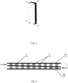
Fig. 1 shows the heat exchanger incorporating stacked modules, in spatial view; -
Fig. 2 presents the module in cross section; -
Fig. 3 depicts the module plate in bird's eye view; -
Fig. 4 shows the arrangement of the turbulising elements on the plate; -
Fig. 5 presents the turbulising element in bird's eye view; -
Fig. 6 depicts the turbulising element in side view; -
Fig. 7 shows the modules in a stack, in cross section. - An embodiment of a plate heat exchange module comprises two
plates turbulising elements 2 with arched side surfaces (Fig. 5, Fig. 6 ), positioned in rows on one side of each ofplate plate Fig. 3 ). - The rib structure may incorporate between 16000 and 39000 turbulising elements per 1 m2 of the surface, not counting the turbulising elements which occupy between 8% and 20% of the surface, respectively.
- The height h of
turbulising elements 2 in the successive rows is different with respect to the neighbouring row by the same value, where the plates are set together so that positioned on oneplate 1A on its side featuring the lowestturbulising elements 2 is the side of theother plate 1B featuring the highestturbulising elements 2, as shown inFig. 2 . - Bodies of
plates plate turbulising elements 2 the cross section of which takes the shape of e.g. aeronautical profile, the leading edge n and the trailing edge s of which are arched in shape, and where the radius of the trailing edge s is smaller than the radius of the leading edge n of the turbulising element 2 (Fig. 5, Fig. 6 ). The point of the maximum width b ofturbulising elements 2 falls at the distance of up to ½ the length ofturbulising element 2 measuring from leading edge n, preferably at 1/10 the length. - The ratio of the maximum width b of
turbulising element 2 and the length l is 1:5, where the width b of the maximum cross section ofturbulising element 2 is 1.2 mm, while its length l is 6 mm.Turbulising elements 2 are distributed evenly on the surface of eachplate turbulising elements 2 of the same row and at the respective end ofturbulising element 2 positioned in the neighbouring row between the saidturbulising elements 2, as shown inFig. 4 . - Height h of
turbulising elements 2 is different depending on the working agent, it also changes in the direction of the flow of the working agent, as described above.Plates frame 3, the width d of which is 3 mm and the height of which depends on height h ofturbulising elements 2 which are found on therespective plate turbulising elements 2. In all corners of each of theplates openings plate frame 3, while the remaining two openings form ducts for the working agent flowing through the plate. The first working agent flows ontoplate 1A via oneopening 4, then it spreads across the plate while flowing all aroundturbulising elements 2 and leaves the plate via the second opening 4', whereopenings 5, 5' on thatplate 1A are blinded withframe 3. On the other hand, onplate 1B, the second working agent flows onto that plate via oneopening 5 flowing all aroundturbulising elements 2 and leaves via the second opening 5', whereopenings 4, 4' on thatplate 1B are blinded withframe 3. One duct ofplate 1A ends, respectively, withinlet connection 40, and the other duct of the same plate ends with outlet connection 40', while one duct ofplate 1B ends withinlet connection 50 and the other duct of the same plate ends with outlet connection 50'.Plates plate 1A contacts theturbulising elements 2 of thesecond plate 1B, and the module is closed on the top and bottom withend plates 6 the thickness of which is 8 mm. - In another embodiment, there is a separating plate (not shown on the drawing) between
plates - In one embodiment, the flat side of one
plate 1A contacts theturbulising elements 2 of theother plate 1B at the point where theturbulising elements 2 of thesecond plate 1B are situated, and in another embodiment the flat side of oneplate 1A contacts theturbulising elements 2 of thesecond plate 1B at the point where someturbulising elements 2 of thesecond plate 1B are situated, i.e. with a slight mutual shift ofturbulising elements 2 ofplates - In other embodiments, the cross section of
turbulising elements 2 may be given the shape of a circle or ellipse (not shown on the drawing).Turbulising elements 2 on oneplate - Moreover,
turbulising elements 2 may be distributed on bothplates turbulising elements 2 on bothplates turbulising elements 2 on bothplates - Moreover,
plates turbulising elements 2, and frames 3 may be made of the same material. - The module may incorporate two types of
plates - For example, one of the working agents may be R513A, and the other may be water. In the solution according to this invention the height h of
turbulising elements 2 changes (increases or decreases in line with the direction of the flow of the agent), irrespective of the working agent used in the module so that each successive row (in line with the direction of the flow of the working agent) ofturbulising elements 2 is higher or lower than in the preceding row, as the result of which the surfaces of any neighbouring plates are not parallel to each other, unlike in the known plate exchangers. The above enables obtaining a flow space the cross section of which increases or decreases in line with the direction of flow of the agent, which ensures increasing the effective cross section while the volume of the agent from heat exchange changes. - In the cases where the working agent is R513A,
turbulising elements 2 are characterised by height increasing in the direction of flow of the working agent, which is advantageous because the working agent changes its state of matter during the operation of the device from liquid to gaseous, as the result of which it increases in volume 1.5 times. If the flow space is constant in cross section, the resistance caused by the change in velocity of the boiling working agent would be 2.25 than higher than in the case of the flow of the same agent in the liquid state. For this reason, the space for the flow of that working agent is characterized by changing cross section. The height h of the first row ofturbulising elements 2 is 1 mm, while the height of the last row ofturbulising elements 2 is 2 mm, thanks to which the area of the effective crossn section at the outlet is twice larger which in turn enables fourfold reduction of the flow resistances. In the case of the second working agent, i.e. water, the space of flow is also characterised by changing cross section. The height of the first row ofturbulising elements 2 is 2 mm, while of the last row is 3 mm. This is advantageous because the area of the smaller heights of the turbulising elements on the water side corresponds to the area on the side of the second working agent, where R513A present there in the gaseous state is characterised by nearly 10 times lower heat transfer coefficient than in the evaporation process. The smaller effective cross section for the flow of water intensifies heat transfer coefficient on the water side, thanks to which the required heat exchange surface in this area can be smaller than in the case of a flow space characterised by constant cross section, which leads to the reduction of weight and volume of the module, and in the case of module multiplication to the reduction of weight and volume of the exchanger. The increasing effective cross section, on the other hand, enables reduction of high flow resistances which would be caused by excessively high speed of the water flow, where the speed is not necessary for operation of the device in the areas where R513A evaporates and is characterized by very high heat transfer coefficient. -
- 1A - module plate
- 1B - module plate
- 2 - turbulising elements
- b - width of the turbulising elements
- 1 - length of the turbulising elements
- h - height of the turbulising elements
- k - distance between rows of the turbulising elements
- n - leading edge of a turbulising element
- s - trailing edge of a turbulising element
- 3 - frame
- d - width of the frame
- 4 - inlet opening for the first agent
- 4' - outlet opening for the first agent
- 5 - inlet opening for the second agent
- 5' - outlet opening for the second agent
- 6 - end plates of the module
- 7 - separating plate
- 40 - inlet connection for the first agent
- 40' - outlet connection for the first agent
- 50 - inlet connection for the second agent
- 50' - outlet connection for the second agent
Claims (15)
- A plate heat exchange module comprising two plates featuring a rib structure, where each plate is fitted with an inlet connection and an outlet connection for the working agent which flows through the plate, characterised in that the rib structure takes the form of turbulising elements (2) arranged in rows on one side of each of the plates (1A, 1B), while the other side of each plate (1A, 1B) is flat, where the height (h) of the turbulising elements (2) in any successive row is different with respect to the preceding row by the same value, and where the plates (1A, 1B) are set together so that positioned on one plate on its side which features the lowest turbulising elements (2) is the side of the other plate with the highest turbulising elements (2).
- The module according to claim 1, characterised in that the side surface of turbulising elements (2) is arched.
- The module according to claim 1, characterised in that the flat side of one plate (1A) contacts the turbulising elements (2) of the other plate (1B).
- The module according to claim 1, characterised in that placed between the plates (1A, 1B) with the rib structure thereon is a separating plate (7).
- The module according to claim 3, characterised in that the flat side of one plate (1A) contacts the turbulising elements (2) of the other plate (1B) at the point where the turbulising elements (2) of the other plate (1B) are positioned.
- The module according to claim 3, characterised in that the flat side of one plate (1A) contacts the turbulising elements (2) of the other plate (1B) at the point where some of the turbulising elements (2) of the other plate (1B) are positioned.
- The module according to any one of the claims 1 to 6, characterised in that the turbulising elements (2) are set in an arrangement based on an equilateral triangle so that the distance (k) between the rows equals the height of the equilateral triangle the apexes of which are positioned at the ends of two neighbouring turbulising elements (2) of the same row and at the respective end of the turbulising element (2) positioned in the neighbouring row between the said turbulising elements (2).
- The module according to any one of the claims 1 to 7, characterised in that the cross section of the turbulising elements (2) has the shape of the aeronautical profile or ellipse.
- The module according to claim 8, characterised in that the width (b) of the turbulising elements (2) does not exceed 7mm.
- The module according to claim 8 or 9, characterised in that the length of the turbulising elements (2) does not exceed 15 mm.
- The module according to any one of the claims 1 to 7, characterised in that the cross section of the turbulising elements (2) has the shape of a circle.
- The module according to claim 11, characterised in that the diameter of turbulising elements (2) is not larger than 15mm.
- The module according to claim 8, characterised in that the point of the maximum width (b) of the turbulising elements (2) falls no farther than 0.5 the length (l) of the turbulising element (2) when measuring from the leading edge (n), preferably at 0.10 the length (l).
- The module according to any one of the claims 1 to 13, characterised in that the height (h) of turbulising elements (2) in one plate (1A) is different that the height of the turbulising elements in the second plate (1B).
- The module according to any one of the claims 1 to 14, characterised in that the end plates (6) of the module are parallel to each other.
Applications Claiming Priority (1)
| Application Number | Priority Date | Filing Date | Title |
|---|---|---|---|
| PL446757A PL248910B1 (en) | 2023-11-17 | 2023-11-17 | Plate heat exchange module |
Publications (1)
| Publication Number | Publication Date |
|---|---|
| EP4556840A1 true EP4556840A1 (en) | 2025-05-21 |
Family
ID=94083199
Family Applications (1)
| Application Number | Title | Priority Date | Filing Date |
|---|---|---|---|
| EP24020330.7A Pending EP4556840A1 (en) | 2023-11-17 | 2024-11-15 | Plate heat exchange module |
Country Status (2)
| Country | Link |
|---|---|
| EP (1) | EP4556840A1 (en) |
| PL (1) | PL248910B1 (en) |
Citations (7)
| Publication number | Priority date | Publication date | Assignee | Title |
|---|---|---|---|---|
| KR100990309B1 (en) * | 2008-06-03 | 2010-10-26 | 한국수력원자력 주식회사 | heat transmitter |
| EP2645038A1 (en) | 2012-03-29 | 2013-10-02 | Linde Aktiengesellschaft | Plate heat exchanger with multiple modules connected with profiles |
| US20170321973A1 (en) * | 2016-05-09 | 2017-11-09 | Hamilton Sundstrand Corporation | Constant vapor velocity condenser |
| US20180120038A1 (en) * | 2013-07-26 | 2018-05-03 | Hamilton Sundstrand Corporation | Heat exchanger with embedded heat pipes |
| EP3957940A1 (en) | 2019-09-02 | 2022-02-23 | Olivier Brasseur | Counterflow plate heat exchanger module and counterflow plate heat exchanger |
| EP4089359A1 (en) | 2021-05-10 | 2022-11-16 | Danfoss A/S | A plate for a plate kind heat exchanger with asymmetrical corrugations |
| US20230175785A1 (en) | 2020-03-23 | 2023-06-08 | Reaction Engines Ltd | Flat plate heat exchanger |
Family Cites Families (3)
| Publication number | Priority date | Publication date | Assignee | Title |
|---|---|---|---|---|
| US2872165A (en) * | 1954-09-04 | 1959-02-03 | Separator Ab | Plate type heat exchanger |
| NL1018672C2 (en) * | 2001-07-31 | 2003-02-06 | Stichting Energie | System for stripping and rectifying a fluid mixture. |
| CZ2007899A3 (en) * | 2007-12-27 | 2009-07-08 | Dinulescu@Mircea | Heat exchanger |
-
2023
- 2023-11-17 PL PL446757A patent/PL248910B1/en unknown
-
2024
- 2024-11-15 EP EP24020330.7A patent/EP4556840A1/en active Pending
Patent Citations (7)
| Publication number | Priority date | Publication date | Assignee | Title |
|---|---|---|---|---|
| KR100990309B1 (en) * | 2008-06-03 | 2010-10-26 | 한국수력원자력 주식회사 | heat transmitter |
| EP2645038A1 (en) | 2012-03-29 | 2013-10-02 | Linde Aktiengesellschaft | Plate heat exchanger with multiple modules connected with profiles |
| US20180120038A1 (en) * | 2013-07-26 | 2018-05-03 | Hamilton Sundstrand Corporation | Heat exchanger with embedded heat pipes |
| US20170321973A1 (en) * | 2016-05-09 | 2017-11-09 | Hamilton Sundstrand Corporation | Constant vapor velocity condenser |
| EP3957940A1 (en) | 2019-09-02 | 2022-02-23 | Olivier Brasseur | Counterflow plate heat exchanger module and counterflow plate heat exchanger |
| US20230175785A1 (en) | 2020-03-23 | 2023-06-08 | Reaction Engines Ltd | Flat plate heat exchanger |
| EP4089359A1 (en) | 2021-05-10 | 2022-11-16 | Danfoss A/S | A plate for a plate kind heat exchanger with asymmetrical corrugations |
Also Published As
| Publication number | Publication date |
|---|---|
| PL446757A1 (en) | 2025-05-19 |
| PL248910B1 (en) | 2026-02-09 |
Similar Documents
| Publication | Publication Date | Title |
|---|---|---|
| EP2469215B1 (en) | Tube heat exchanger | |
| US6273183B1 (en) | Heat exchanger turbulizers with interrupted convolutions | |
| EP3832243B1 (en) | Multi-stage flow distribution plate group for heat exchanger | |
| EP2455695B1 (en) | Heat exchanger | |
| US4804041A (en) | Heat-exchanger of plate fin type | |
| GB2089226A (en) | Plate evaporator | |
| US5755281A (en) | Fin tube heat exchanger | |
| EP0162828B1 (en) | Heat exchanger | |
| CN111780596B (en) | Plate-tube heat exchanger | |
| EP1058078A2 (en) | Condenser | |
| US20080047696A1 (en) | Heat transfer surfaces with flanged apertures | |
| JP5763462B2 (en) | Header plateless heat exchanger | |
| EP4556840A1 (en) | Plate heat exchange module | |
| JPS59229193A (en) | Heat exchanger | |
| EP1007893B1 (en) | Heat exchanger turbulizers with interrupted convolutions | |
| US20250012513A1 (en) | Heat exchanger core layer | |
| CN211178074U (en) | Second plate for multi-stage flow-dividing brazing heat exchanger plate group | |
| CN110749217A (en) | First plate for multi-stage flow-dividing brazing heat exchanger plate group | |
| EP2064509B1 (en) | Heat transfer surfaces with flanged apertures | |
| KR101315648B1 (en) | Plate-type heat exchanger | |
| EP4556839A1 (en) | Heat exchanger | |
| CN212300011U (en) | Heat exchanger and air conditioning unit | |
| KR20150073732A (en) | Improved Primary Surface Heat Exchanger for Micro Gas Turbine | |
| CN211012599U (en) | Multi-stage flow-dividing brazing heat exchanger plate set | |
| EP0044734A2 (en) | Heat exchanger |
Legal Events
| Date | Code | Title | Description |
|---|---|---|---|
| PUAI | Public reference made under article 153(3) epc to a published international application that has entered the european phase |
Free format text: ORIGINAL CODE: 0009012 |
|
| STAA | Information on the status of an ep patent application or granted ep patent |
Free format text: STATUS: THE APPLICATION HAS BEEN PUBLISHED |
|
| AK | Designated contracting states |
Kind code of ref document: A1 Designated state(s): AL AT BE BG CH CY CZ DE DK EE ES FI FR GB GR HR HU IE IS IT LI LT LU LV MC ME MK MT NL NO PL PT RO RS SE SI SK SM TR |
|
| STAA | Information on the status of an ep patent application or granted ep patent |
Free format text: STATUS: REQUEST FOR EXAMINATION WAS MADE |
|
| 17P | Request for examination filed |
Effective date: 20251119 |