EP4556819A1 - Heat pump system - Google Patents
Heat pump system Download PDFInfo
- Publication number
- EP4556819A1 EP4556819A1 EP23210005.7A EP23210005A EP4556819A1 EP 4556819 A1 EP4556819 A1 EP 4556819A1 EP 23210005 A EP23210005 A EP 23210005A EP 4556819 A1 EP4556819 A1 EP 4556819A1
- Authority
- EP
- European Patent Office
- Prior art keywords
- refrigerant
- heat pump
- pump system
- expansion valve
- aperture
- Prior art date
- Legal status (The legal status is an assumption and is not a legal conclusion. Google has not performed a legal analysis and makes no representation as to the accuracy of the status listed.)
- Pending
Links
Images

Classifications
-
- F—MECHANICAL ENGINEERING; LIGHTING; HEATING; WEAPONS; BLASTING
- F25—REFRIGERATION OR COOLING; COMBINED HEATING AND REFRIGERATION SYSTEMS; HEAT PUMP SYSTEMS; MANUFACTURE OR STORAGE OF ICE; LIQUEFACTION SOLIDIFICATION OF GASES
- F25B—REFRIGERATION MACHINES, PLANTS OR SYSTEMS; COMBINED HEATING AND REFRIGERATION SYSTEMS; HEAT PUMP SYSTEMS
- F25B41/00—Fluid-circulation arrangements
- F25B41/30—Expansion means; Dispositions thereof
- F25B41/31—Expansion valves
- F25B41/33—Expansion valves with the valve member being actuated by the fluid pressure, e.g. by the pressure of the refrigerant
- F25B41/335—Expansion valves with the valve member being actuated by the fluid pressure, e.g. by the pressure of the refrigerant via diaphragms
-
- F—MECHANICAL ENGINEERING; LIGHTING; HEATING; WEAPONS; BLASTING
- F25—REFRIGERATION OR COOLING; COMBINED HEATING AND REFRIGERATION SYSTEMS; HEAT PUMP SYSTEMS; MANUFACTURE OR STORAGE OF ICE; LIQUEFACTION SOLIDIFICATION OF GASES
- F25B—REFRIGERATION MACHINES, PLANTS OR SYSTEMS; COMBINED HEATING AND REFRIGERATION SYSTEMS; HEAT PUMP SYSTEMS
- F25B41/00—Fluid-circulation arrangements
- F25B41/30—Expansion means; Dispositions thereof
- F25B41/39—Dispositions with two or more expansion means arranged in series, i.e. multi-stage expansion, on a refrigerant line leading to the same evaporator
-
- F—MECHANICAL ENGINEERING; LIGHTING; HEATING; WEAPONS; BLASTING
- F25—REFRIGERATION OR COOLING; COMBINED HEATING AND REFRIGERATION SYSTEMS; HEAT PUMP SYSTEMS; MANUFACTURE OR STORAGE OF ICE; LIQUEFACTION SOLIDIFICATION OF GASES
- F25B—REFRIGERATION MACHINES, PLANTS OR SYSTEMS; COMBINED HEATING AND REFRIGERATION SYSTEMS; HEAT PUMP SYSTEMS
- F25B2341/00—Details of ejectors not being used as compression device; Details of flow restrictors or expansion valves
- F25B2341/06—Details of flow restrictors or expansion valves
- F25B2341/063—Feed forward expansion valves
-
- F—MECHANICAL ENGINEERING; LIGHTING; HEATING; WEAPONS; BLASTING
- F25—REFRIGERATION OR COOLING; COMBINED HEATING AND REFRIGERATION SYSTEMS; HEAT PUMP SYSTEMS; MANUFACTURE OR STORAGE OF ICE; LIQUEFACTION SOLIDIFICATION OF GASES
- F25B—REFRIGERATION MACHINES, PLANTS OR SYSTEMS; COMBINED HEATING AND REFRIGERATION SYSTEMS; HEAT PUMP SYSTEMS
- F25B2700/00—Sensing or detecting of parameters; Sensors therefor
- F25B2700/21—Temperatures
- F25B2700/2115—Temperatures of a compressor or the drive means therefor
- F25B2700/21151—Temperatures of a compressor or the drive means therefor at the suction side of the compressor
-
- F—MECHANICAL ENGINEERING; LIGHTING; HEATING; WEAPONS; BLASTING
- F25—REFRIGERATION OR COOLING; COMBINED HEATING AND REFRIGERATION SYSTEMS; HEAT PUMP SYSTEMS; MANUFACTURE OR STORAGE OF ICE; LIQUEFACTION SOLIDIFICATION OF GASES
- F25B—REFRIGERATION MACHINES, PLANTS OR SYSTEMS; COMBINED HEATING AND REFRIGERATION SYSTEMS; HEAT PUMP SYSTEMS
- F25B2700/00—Sensing or detecting of parameters; Sensors therefor
- F25B2700/21—Temperatures
- F25B2700/2116—Temperatures of a condenser
- F25B2700/21163—Temperatures of a condenser of the refrigerant at the outlet of the condenser
Definitions
- the present invention is directed to a heat pump system. Moreover, the present invention relates to a method for operating such a heat pump system.
- Heat pump systems are systems enabling heating and/or cooling.
- Heat pump systems may be heat pump devices with or without a reversible refrigerant circuit, refrigerators, or air conditioning systems, to name a few. They all allow to transport heat from one medium to a second medium.
- One of the common features of such heat pump systems is that they are used for conducting a thermodynamic cycle by means of a refrigerant, the thermodynamic cycle being composed of the following steps:
- Figure 1 shows a phase diagram of a given refrigerant regarding pressure p and enthalpy h.
- the line S is a separation line between the different phases of the refrigerant.
- the refrigerant In the area L the refrigerant is liquid, in the area V the refrigerant is gaseous.
- the refrigerant In the area TP the refrigerant is present in a mixture of vapor and liquid. Evaporation takes place starting from the point X4 to X1, compression from X1 to X2, condensation from X2 to X3 and expansion between X3 to X4.
- thermodynamic cycle in the phase diagram according to Figure 1 would thus be a rectangle and not a trapezoidal shape as it is.
- the amount of refrigerant admitted to the evaporator is regulated in the expansion device, the amount of refrigerant being related to the pressure. If there is not enough refrigerant in the evaporator, the refrigerant is too quickly evaporated, and the available capacity is not fully exploited. If there is too much refrigerant in the evaporator, not the entire refrigerant can evaporate such that there is a risk of liquid in the compressor, which can lead to damages of the compressor.
- the fluid will be heated more than necessary to ensure that there is no liquid in the fluid when it enters the compressor.
- This measure is also referred to as superheating SH.
- superheating ensures that all available energy at the evaporator is fully exploited. Due to the superheating SH and the additional energy received from the compressor, there is a certain quantum of energy available at the entry of the condenser which needs to be removed before the phase transition of the refrigerant starts upon condensation and thus only leads to a temperature change. This heat is a sensible heat, while the heat leading to a phase transition is a latent heat. The transfer of the sensible heat prior to condensation is called de-superheating DSH.
- subcooling SC the refrigerant is cooled down more than necessary.
- the subcooling ensures that all the energy available has been shared in the condenser.
- Subcooling is a sensible heat and thus a heat exchanged without phase transition. In the case of subcooling, the heat transfer is done in the liquid phase.
- Heat exchanges related to sensible heat are less efficient than heat exchanges related to latent heat (phase change of the fluid). It is therefore desirable to limit overheating, de-superheating DSH and preferably subcooling SC in heat pump systems for heating application.
- the capillary regulator comprises a pipe with a very small inner diameter (typically between 0,5 mm and 2 mm) compared to the diameter of the piping of the remaining system (in general between 5 mm and 12mm). It is also very long compared to the remaining piping and can reach several meters.
- the expansion of the refrigerant and the management of the flow is realized by this passage in the capillary.
- capillary regulator is very reliable and inexpensive. However, only a constant flow of the refrigerant can be provided. It is not dependent on the state of the system and in particular the temperatures of the circuit or the environment. As a result, the superheating at the evaporator will be variable. The operation of the product cannot be optimized as it must be ensured that a minimum superheating is available during all operating modes. Thus, such capillary regulator is not suitable for heat pumps or air-conditioning systems.
- the electronic expansion valve and the thermostatic expansion valve work on the same principle:
- the refrigerant flows through an orifice typically formed by a valve seat.
- the expansion valve comprises an actuator, typically a needle, the position of which is changeable, thereby allowing a certain volume of refrigerant to pass.
- the volume can be regulated by either totally or partially closing the orifice by the needle.
- the needle is moved by a motor.
- This can be a stepper motor that sets a precise position for the needle or an impulse motor that allows the refrigerant to pass at a greater or lesser frequency.
- the expansion valve acts to ensure that the refrigerant is properly superheated. To do so, temperature and/or pressure measurements of the refrigerant are taken by sensors positioned in the circuit pipe. These measurements are conducted at the evaporator outlet. Depending on the results of the measurements, a controller activates the motor to open or close the expansion valve.
- the opening and closing of the needle is done fully mechanically, without the use of a motor and associated electronic.
- the needle is combined with a diaphragm.
- This diaphragm interacts with a detecting fluid which is brought into contact with the circuit pipe.
- the measuring fluid expands or compresses, thereby moving the needle.
- thermodynamic cycle it is one task of one embodiment of the present invention to provide a heat pump system in which a fine and reliable control of the thermodynamic cycle can be achieved, thereby improving the overall performance of the thermodynamic cycle, especially for heating application.
- an embodiment of the present invention has the object to provide a method for operating such a heat pump system.
- the heat pump system for heating and/or cooling a refrigerant comprising:
- the senor is not considered to be a part of the expansion valve, albeit interacting with the same. However, it can be an integral part of the condenser or the thermostatic expansion device and not necessarily a separate unit that is arranged between and at distance from the condenser and the thermostatic expansion device.
- the temperature of the refrigerant that has left the condenser but not yet entered the thermostatic expansion device is used for adjusting the opening degree of the aperture.
- the thermostatic expansion device adjusts the opening degree of the aperture or in other words, the size of the cross section of the aperture through which the refrigerant can pass. Under normal operational conditions, the aperture is usually neither fully opened nor fully closed.
- a sensor bulb is a sensor which includes a fluid that dilates according to temperature or pressure of the refrigerant.
- the heat pump system can be used at least for a heating application.
- thermodynamic cycle is not controlled based on the superheating but based on the subcooling. It has been found that the overall performance of the thermodynamic cycle can be improved by reducing the subcooling.
- the control of the thermodynamic cycle is done by mechanical means without the need of electronic components. The control is thus more reliable and independent of the supply of electric energy.
- the thermostatic expansion device comprises an opening adjusting unit having an actuator that is movable by the detecting fluid and the refrigerant for adjusting the opening degree of the aperture.
- the opening degree of the aperture can be changed by a fairly simple mechanism which adds to the reliability of the heat pump system and at the same time keeps the manufacturing costs low.
- the opening adjusting unit may be manufactured as a separate unit and pre-mounted before the entire thermostatic expansion device is assembled.
- the thermostatic expansion device comprises a diaphragm that is deformable at least by the detecting fluid, wherein the deformation of the diaphragm is transferred to the actuator causing the movement of the actuator.
- the expansion valve comprises a diaphragm that is deformable at least by the detecting fluid, wherein the deformation of the diaphragm is transferred to the actuator causing the movement of the actuator.
- the diaphragm can also be deformed by the refrigerant.
- the pressure of the detecting fluid is acting on the first surface while the pressure of the refrigerant is acting on the second surface.
- the actuator is moved according to the resulting pressure difference.
- flow rate of refrigerant from the liquid phase to the gas phase entering the evaporator is defined by the pressure difference.
- This flow rate is thus optimally defined according to the subcooling temperature.
- the objective is set the subcooling towards zero, while remaining positive, thereby further increasing the performance of the thermodynamic cycle and allowing for a reduction of the amount of refrigerant used in the system. Reducing the amount of fluid in the circuit leads to a reduction in resource consumption and improved user safety, particularly when using flammable fluids..
- the opening adjusting unit comprises an adjustment unit for setting the opening degree of the aperture.
- the subcooling set point can be changed by means of the adjustment unit depending on the product in question and the associated conditions of use of the respective product.
- the adjustment unit may include a biasing element like a spring, the tension of which may be regulated by a setting screw. Depending on the tension the pressure required to change the opening degree of the aperture can be changed.
- the spring ensures that the system does not remain in the closed position and avoids jamming on start-up. It also ensures that the forces at the needle are balanced and that the opening level is adapted to the system.
- the heat pump system comprises a heat exchange means arranged between the condenser and the expansion valve, wherein the circuit pipe between the evaporator and the compressor passes through the heat exchange means.
- the heat withdrawn from the refrigerant between the condenser and the expansion valve is used to heat the refrigerant before entering the compressor.
- the heat pump system comprises a first buffering container arranged in the circuit pipe between the evaporator and the compressor.
- the thermodynamic cycle is controlled based on the subcooling.
- the risk of remaining droplets the refrigerant after having left the evaporator may be increased by this control strategy.
- the first buffering container compensates for this risk as potential liquid refrigerant in the circuit pipe is retained before entering the compression chamber.
- the presence of liquid in the compression chamber of a compressor can cause damage. It is therefore important to ensure that only gaseous refrigerant can enter the compressor.
- a further embodiment is characterized in that the circuit pipe between the first buffering container and the compressor passes through the heat exchange means.
- the heat withdrawn from the refrigerant between the condenser and the expansion valve is transferred to the refrigerant stored in the first buffering container.
- Liquid droplets that may remain in the refrigerant and stored in the first buffering container can be evaporated.
- the entire refrigerant can be processed, thereby increasing the overall performance of the thermodynamic cycle.
- the heat exchange from the condenser outlet to the tube before entering the compressor does not result in a loss of system performance, since the heat at the condenser outlet was no longer being used to produce heat anyway.
- the term “measuring the temperature or pressure” should be understood such that a certain value of the temperature or pressure of the refrigerant is determined which may be displayed and/or used for calculations.
- the sensing unit typically comprises electronical components.
- the term “reacting according to the temperature or pressure” is to be understood such that the temperature or pressure causes a certain reaction in this case of the further expansion device without a certain value of the temperature or pressure to be determined.
- the sensing unit typically comprises mechanical components only.
- the sensing unit can be an integral part of the compressor or the further thermostatic expansion device and not necessarily a separate unit that is arranged between and at distance from the compressor and the evaporator. In any case, the temperature or pressure of the refrigerant that has left the evaporator but not yet entered the compressor is used for adjusting the opening degree of the aperture.
- thermodynamic cycle is controlled based on the subcooling.
- superheating is considered in the control of the thermodynamic cycle.
- a performance improvement due to the subcooling management described above is obtained next to an improved reliability of the system of a system managed with superheating (for example to avoid liquid droplets into the compression chamber).
- the heat pump system is configured such that it reacts on both subcooling and superheating.
- control of the further expansion valve is done by mechanical means without the need of electronic components.
- the control is thus more reliable and independent of the supply of electric energy.
- the further opening adjusting unit comprises a motor by which the further actuator is movable for adjusting the opening degree of the further aperture, the motor being activatable by the sensing unit.
- the thermodynamic cycle is controlled by electronic means. Compared to a mechanical control, the possibilities to influence the thermodynamic cycle are bigger when using electronic means.
- various control strategies can be implemented to set the subcooling towards zero and to consider the superheating in the control of the thermodynamic cycle.
- the heat pump system comprises a second buffering container arranged in the circuit pipe between the expansion valve and the further expansion valve.
- the second buffering container acts as a buffer, in this embodiment between the first expansion valve and the further expansion valves.
- the refrigerant leaving the expansion valve may partially be in the liquid phase and partially in the gas phase.
- the refrigerant is separated as the liquid part will accumulate at the bottom of the second buffering container.
- the liquid refrigerant can flow to the further expansion valve.
- the gaseous refrigerant will be stored until condensation to the liquid phase when the pressure in the second buffering container increases. Thanks to this system, only liquid refrigerant enters the further expansion valve, thereby improving the reliability of the functioning of the further expansion valve.
- the second connection pipe is preferably arranged at the top of the second buffering container. In doing so, the gaseous portion of the refrigerant coming from the expansion valve will flow through the second connection pipe and will bypass the evaporator. The liquid portion of the refrigerant, on the other hand, will still be processed in the evaporator so as to evaporate and be converted into gas. The two gas flows will then join before entering the compressor. With the second connection pipe connected with the second buffering container at its top, the already gaseous portion of the refrigerant will be used without having to go back to liquid form and pass through the evaporator. The overall performance of the thermodynamic cycle can thus be improved.
- Another aspect of the invention is directed towards a method for operating heat pump system according to one of the preceding embodiments, the method comprising the following steps:
- thermodynamic cycle is not controlled based on the superheating but based on the subcooling. It has been found that the overall performance of the thermodynamic cycle can be improved by reducing the subcooling.
- a direct control based on the subcooling can be established to reduce the subcooling as far and as quickly as possible. Therefore, the overall performance of the thermodynamic cycle can be effectively improved.
- the method comprising the following steps: measuring the temperature or pressure of the refrigerant using the sensing unit between the evaporator and the compressor, and adjusting the opening degree of the aperture according to an interaction between the sensing unit and the further expansion device depending on the measured temperature or pressure of the refrigerant.
- the temperature or pressure is measured, i.e., a certain value is determined which may be transferred to a control device which considers this value in the activation of the actuator of the further expansion device.
- a control device which considers this value in the activation of the actuator of the further expansion device.
- a motor is used for moving the actuator that is actuated by the control device.
- the method comprising the following steps:
- the temperature or pressure causes a certain reaction in this case of the further expansion device without a certain value of the temperature or pressure to be determined.
- the sensing unit typically comprises mechanical components only.
- the method comprises the step of adjusting the opening degree of the aperture and the further aperture such that the subcooling tends to 0K and is strictly positive, the subcooling being between more than 0K and less than 20K, preferably between 1Kto 8K.
- the overall performance of the thermodynamic cycle is optimized.
- FIG 1 shows a phase diagram of a given refrigerant represented by pressure p and enthalpy h.
- the line S is a separation line between the different phases of the refrigerant.
- the refrigerant In the area L the refrigerant is liquid, in the area V the refrigerant is evaporated.
- the refrigerant In the area TP the refrigerant is present in a mixture of vapor and liquid. Evaporation takes place starting from the point X4 to X1 in an evaporator 14, compression from X1 to X2 in a compressor 16, condensation from X2 to X3 in a condenser 18 and expansion between X3 to X4 in an expansion valve 20 (see e.g. Figure 2 )
- thermodynamic cycle in the phase diagram according to Figure 1 would thus be a rectangle.
- subcooling SC On the other hand, at the outlet of the condenser 18, the refrigerant is cooled down more than necessary. This is referred to as subcooling SC.
- the subcooling SC ensures that all the energy available has been shared in the condenser 18.
- Subcooling SC is a sensible heat and thus a heat exchanged without phase transition. In the case of subcooling SC, the heat transfer is done in the liquid phase.
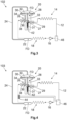
- FIG. 2 shows a first embodiment of a heat pump system 101 according to the present invention.
- the heat pump system 101 comprises a circuit pipe 12 along which a refrigerant can be circulated, an evaporator 14 arranged in the circuit pipe 12 for evaporating the refrigerant, a compressor 16 arranged in the circuit pipe 12 for compressing the evaporated refrigerant, a condenser 18 arranged in the circuit pipe 12 for liquefying the compressed refrigerant, and an expansion valve 20 arranged in the circuit pipe 12 for expanding the liquefied refrigerant.
- the thermostatic expansion device 20 comprises an opening adjusting unit 26 that comprises a valve seat 29 that defines an aperture 27.
- the opening adjusting unit 26 may be equipped with an actuator 28 comprising a needle 33 that interacts with a valve seat 29.
- the opening degree of the aperture 27 depends on the position of the needle 33.
- the opening adjusting unit 26 further comprises a biasing element 31 such as a spring for moving back the needle into its starting position.
- the thermostatic expansion valve 20 is further equipped with an adjustment unit 42 that is interacting with the biasing element 31.
- the adjustment unit 42 may comprise a screw by which the reset force of the biasing element 31 can be changed.
- the thermostatic expansion valve 20 further comprises diaphragm 30 having a first surface 32 and a second surface 34.
- the second surface 34 is interacting with the opening adjusting unit 26 and in particular with the actuator 28.
- the circuit pipe 12 comprises a first branch point 36 which is in the embodiment shown located inside the thermostatic expansion valve 20 but could also be arranged outside the expansion valve 20 (see Figure 5 ).
- a first connecting line 38 starts from the first branch point 36 and establishes a connection with the second surface 34 of the diaphragm 30 such that the refrigerant can interact with the second surface 34.
- the device comprises a sensor bulb 22 that reacts depending on at least one process parameter of the refrigerant, especially the temperature of the refrigerant.
- the sensor bulb 22 is not part of the expansion valve 20 but is arranged between the condenser 18 and the expansion valve 20.
- the sensor bulb 22 is interacting with the opening adjusting unit 26 for opening and closing the thermostatic expansion valve 20 depending on the measured process parameter as will be explained in greater detail in the following.
- the sensor bulb 22 is embodied as a bulb and connected to the opening adjusting unit 26 by a reacting line 24, the reacting line 24 being filled with a detecting fluid FD.
- the detecting fluid FD is expanded or compressed. The change in volume creates a change of the pressure exerted by the detecting fluid FD on the first surface 32 of the diaphragm 30.
- the refrigerant is acting on the second surface 34 of the diaphragm 30.
- the refrigerant arrives from the condenser 18 at high pressure and in liquid phase. The pressure is balanced on the second surface 34 of the diaphragm 30.
- the supercooling SC can be reduced to a predeterminate value (>0 and below a threshold value) and to ensure a lower temperature of the refrigerant in the condenser 18.
- a predeterminate value >0 and below a threshold value
- the thermostatic expansion device 20 will adapt the mass flow rate in the circuit pipe 12 to be compliant with the aimed supercooling SC.
- the thermostatic expansion device 20 will update the system to reduce the mass flow rate in the circuit pipe 12 to reach this target. If the temperature at the end of the condenser 18 is too high, the pressure of the detecting fluid FD in sensor bulb 22 and so in the upper section of the thermostatic expansion device 20 will increase. It will push on the actuator 28 to remove the opening degree of the aperture 27. The mass flow rate will decrease in the whole heat pump system 101 until the desired value at the temperature of the condenser 18 is reached. By reducing the flow rate in the circuit pipe 12, the temperature in the condenser 18.
- the actuator 28 will therefore be moved down to further close the expansion valve 20. In doing so, more refrigerant will remain in the condenser 18 and the mass flow rate will increase. This will increase the energy exchange in the condenser 18, thereby fully exploiting the potential of the refrigerant.
- the diaphragm 30 moves and causes the actuator 28 to move accordingly.
- the needle of the actuator 28 is used to precisely open the flow rate through the expansion valve 20.
- the flow rate of refrigerant from the liquid phase to the gas phase entering the evaporator 14 is defined. This flow rate is thus optimally defined according to the subcooling SC temperature.
- the adjustment unit 42 can be set accordingly.
- the objective is to make this subcooling SC tend towards zero, while remaining positive.
- the objective is to keep the subcooling SC below a threshold value. This value is preferably from 1 to 20K, especially from 1 to 8K.
- the refrigerant acting on the second surface 34 of the diaphragm 30 is in the liquid phase and under high pressure.
- the movement of the actuator 28 can be better reversed.
- the control of the thermodynamic cycle is more precise and faster.
- the adjustment unit 42 can effectively be employed. At low pressure levels, the reset forces of a typical biasing element 31 would be far too high to effectively adjust the pressure difference needed to move the actuator 28 towards the valve seat 29.
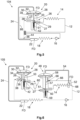
- FIG. 3 shows a second embodiment of the heat pump system 102 according to the present invention.
- the heat pump system 102 of the second embodiment comprises a first buffering container 46 arranged in the circuit pipe 12 between the evaporator 14 and the compressor 16. It cannot be excluded that the refrigerant is not fully evaporated in the evaporator 14. Instead, some liquid droplets of the refrigerant may remain after the refrigerant has left the evaporator 14. However, the compressor 16 is very sensitive to liquid as it is almost incompressible causing increased wear of the compressor 16.
- the liquid and the evaporated refrigerant are separated from each other.
- the liquid refrigerant accumulates at the bottom of the first buffering container 46.
- the circuit pipe 12 exits the first buffering container 46 spaced from the bottom such that only or almost only evaporated refrigerant is conducted to the compressor 16. The stress and the wear of the compressor 16 can be reduced and its service live prolonged.
- FIG. 4 shows a third embodiment of the heat pump system 103 according to the present invention.
- the heat pump system 103 according to the third embodiment is built largely in the same way as the heat pump system 102 according to the second embodiment.
- a heat exchange means 44 is arranged between the condenser 18 and the expansion valve 20, wherein the circuit pipe 12 between the evaporator 14 and the compressor 16 runs through the heat exchange means 44.
- a separation between the liquid and the evaporated refrigerant is taking place in the first buffering container 46.
- the condenser 18 the compressed evaporated refrigerant is converted into the liquid phase by withdrawing heat from the refrigerant.
- the sensor bulb 22 is arranged between the condenser 18 and the heat exchange means 44 so as not to bias the temperature reading because of this cooling carried out in the heat exchange means 44.
- This cooling in the heat exchange means 44 has no impact on the performance of the thermodynamic cycle since all the desired heat exchange between the refrigerant and the environment to be heated has been conducted in the condenser 18.
- a fourth embodiment of the heat pump system 104 is shown by means of a principle drawing.
- the heat pump system 104 according to the fourth embodiment is to a large extent similar to the heat pump system 103 of the third embodiment and mainly differs in the following:
- the heat pump system 104 does not comprise the first buffering container 46. Instead, the circuit line 12 between the evaporator 14 and the compressor 16 directly runs through the heat exchange means 44.
- the function of the heat exchange means 44 is, however, the same as described with reference to the third embodiment of the heat pump system 103.
- the design of the thermostatic expansion device 20 of the heat pump system 104 of the fourth embodiment differs from the thermostatic expansion device 20 of the heat pump system 103 of the third embodiment at least in the following:
- the first branch point 36 is arranged outside the thermostatic expansion device 20 and is located between the condenser 18 and the heat exchange means 44.
- a pressure equilibration line 66 connects the first branch point 36 and the first connecting line 38 of the thermostatic expansion device 20.
- the refrigerant can interact with the second surface of the diaphragm 30.
- the pressure drop inside the pressure equilibration line 66 may be better influenced in the fourth embodiment of the heat pump system 104, e.g., by the diameter and the length of the pressure equilibration line 66 and/or means of flow restrictors or the like (not shown). A further way to influence the movement of the actuator 28 and thus the flow rate through the thermostatic expansion device 20.
- a heat pump system 105 comprises a further expansion valve 48 arranged in the circuit pipe 12 between the thermostatic expansion valve 20 and the evaporator 14.
- the further expansion valve 48 comprises a further opening adjusting unit 50 forming a further aperture 41.
- a sensing unit 52 is provided which measures at least one process parameter of the refrigerant.
- the sensing unit 52 is arranged between the evaporator 14 and the compressor 16 and is interacting with the further opening adjusting unit 50 for opening and closing the further expansion valve 48 depending on the measured process parameter.
- the sensing unit 52 is connected to the further opening adjusting unit 50 by a further reacting line 54, the further reacting line 54 being filled with a detecting fluid FD which may be the same as used in the sensor bulb 22 that interacts with the expansion valve 20.
- the further opening adjusting unit 50 comprises a further actuator 56 that is movable by the detecting fluid FD for opening and closing the further expansion valve 48.
- the further expansion valve 48 has a further diaphragm 58 that is deformable by the detecting fluid FD, wherein the deformation of the further diaphragm 58 is transferred to the further actuator 56 causing the movement of the further needle 57.
- the heat pump system104 has a second branch point 68 arranged in the circuit pipe 12 between the evaporator 14 and the compressor 16 and a pressure equalization pipe 66 that connects the further opening adjusting unit 50 and the circuit pipe 12 at the second branch point 68.
- thermostatic expansion valve 20 that reacts to subcooling SC, an internal pressure that acts on the second surface 34 of the diaphragm 30 is equivalent to the pressure p of the refrigerant after having left the condenser 18.
- the thermostatic expansion valve 20 allows the subcooling SC to be optimized and to tend towards zero.
- the further expansion valve 48 which reacts according to the superheating SH is located between the expansion valve 20 and the evaporator 14.
- the further sensor 52 is located between the evaporator 14 and the compressor 16. Due to the pressure equalization pipe 66, the pressure under the further diaphragm 58 is equivalent to that of the refrigerant when exiting the evaporator 14.
- the further expansion valve 48 allows the regulation based on superheating SH.
- a target value can be 5 to 7 K.
- the further expansion device 48 is also provided with a further adjustment unit 59 the basic design being to a large extend the same as of the adjustment unit 42 of the thermostatic expansion device 20.
- the further adjustment unit 59 may also comprise a setting screw by which the pre-tensioning force of the biasing element 31 can be changed.
- the further adjustment unit 59 serves for setting the flow rate through the further expansion device 48.
- a second buffering container 60 is arranged in the circuit pipe 12 between the thermostatic expansion valve 20 and the further expansion valve 48.
- the liquid phase will accumulate at the bottom of the second buffering container 60.
- the gaseous refrigerant will be stored until being liquefied when the pressure increases.
- thermodynamic cycle can be optimized as the control of the thermodynamic cycle can be based not only on the subcooling SC but also on the superheating SH.
- FIG. 7 a sixth embodiment of the heat pump system 105 is shown by means of a principle drawing.
- the heat pump system 105 according to the sixth embodiment is to a very large extent similar to the heat pump system 104 according to the fifth embodiment.
- the heat pump system 105 according to the sixth embodiment comprises a third branch point 62 arranged between the evaporator 14 and the compressor 16, and a second connection pipe 64 that connects the second buffering container 60 and the circuit pipe 12 at the third branch point 62.
- the gaseous portion of the refrigerant leaving the expansion valve 20 will flow through the second connection pipe 64 and will bypass the evaporator 14.
- the liquid part on the other hand, will still flow through the evaporator 14 and be converted into gas.
- the two gas flows of the refrigerant will then meet before entering the compressor 16.
- the refrigerant that is already evaporated in the second buffering container 60 does not have to pass the evaporator 14 so that only the liquid portion of the refrigerant is treated in the evaporator 14 thereby increasing the efficiency of the evaporator 14.
- the opening degree of the aperture 27 is decreased when the needle 33 is moved downwards, i.e., towards the adjustment unit 42. Accordingly, the opening degree of the aperture 27 is increased when the needle 33 is moved away from the valve seat 29. In contrast to that, the opening degree of the further aperture 51 is decreased when the further needle 57 is moved upwards, i.e., away from the further adjustment unit 59 and increased when the further needle 57 is moved downwards and towards the further adjustment unit 59.
- the detecting fluid FD acts on the first surface 32 of the diaphragm 30 and the refrigerant on the second surface 34 of the diaphragm 30.
- the further expansion device 48 comprises a motor by which the actuator 28 can be moved.
- the sensing unit 42 is measuring the temperature of the refrigerant. The measured value is transferred to a control device that activates the motor accordingly.
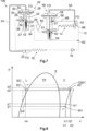
- FIG 8 shows the phase diagram along the lines with Figure 1 for the purpose of demonstrating the optimization of the thermodynamic cycle as previously mentioned.
- the heat pump system 101 - 106 according to the embodiments of the present invention are particularly suited for the optimization of the operation of heat pumps for a heating application.
- heat pumps remove heat from one medium such as air or water or brine and transfer it to another medium such as air, water or brine which can be used for heating a house or for warming water.
- Reducing the subcooling SC to zero or towards zero can be done by lowering the condensing temperature.
- the work done by the compressor 16 is reduced since a lower target temperature is needed and the condensation takes place at a lower pressure level. This results in an enthalpy h2' lower than h2.
- the condensation temperature can be reduced.
- a condensation temperature of around 65 to 75°C must be maintained, whereas it is currently around 75°C to 85°C with the current operating modes.
- the work curve of the compressor 16 is linear, in the form of A*(Tc-Te) with A the linear coefficient of the compressor 16, Tc the condensation temperature at the compressor 16 outlet and T1 the evaporation temperature at the compressor 16 inlet.
- the performance of the system will therefore be improved by reducing the condensation temperature and increasing the evaporation temperature. This is achieved by controlling the subcooling SC and minimizing it. In this case, evaporation takes place starting from the point X4' to X1', compression from X1' to X2', condensation from X2' to X3' and expansion between X3' to X4'.
Landscapes
- Engineering & Computer Science (AREA)
- Physics & Mathematics (AREA)
- Mechanical Engineering (AREA)
- Thermal Sciences (AREA)
- General Engineering & Computer Science (AREA)
- Fluid Mechanics (AREA)
- Compression-Type Refrigeration Machines With Reversible Cycles (AREA)
Abstract
The present invention relates to a heat pump system for heating and/or cooling a refrigerant, comprising:
- a circuit pipe (12) along which the refrigerant can be circulated,
- an evaporator (14) arranged in the circuit pipe (12) for evaporating the refrigerant,
- a compressor (16) arranged in the circuit pipe (12) for compressing the evaporated refrigerant,
- a condenser (18) arranged in the circuit pipe (12) for liquefying the compressed refrigerant,
- a thermostatic expansion valve (20) arranged in the circuit pipe (12) for expanding the liquefied refrigerant, wherein the thermostatic expansion valve (20) comprises an aperture (27), the opening degree of the aperture (27) being adjustable, and
- at least one sensor bulb (22) that
∘ is arranged between the condenser (18) and the thermostatic expansion valve (20), or inside the condenser or inside the expansion valve
∘ reacts according to the temperature or pressure of the refrigerant,
∘ is connected to the thermostatic expansion valve (20) by a reacting line (24) filled with a detecting fluid (FD).
∘ is interacting with the thermostatic expansion device (20) depending on the temperature or pressure of the refrigerant, thereby adjusting the opening degree of the aperture.
- a circuit pipe (12) along which the refrigerant can be circulated,
- an evaporator (14) arranged in the circuit pipe (12) for evaporating the refrigerant,
- a compressor (16) arranged in the circuit pipe (12) for compressing the evaporated refrigerant,
- a condenser (18) arranged in the circuit pipe (12) for liquefying the compressed refrigerant,
- a thermostatic expansion valve (20) arranged in the circuit pipe (12) for expanding the liquefied refrigerant, wherein the thermostatic expansion valve (20) comprises an aperture (27), the opening degree of the aperture (27) being adjustable, and
- at least one sensor bulb (22) that
∘ is arranged between the condenser (18) and the thermostatic expansion valve (20), or inside the condenser or inside the expansion valve
∘ reacts according to the temperature or pressure of the refrigerant,
∘ is connected to the thermostatic expansion valve (20) by a reacting line (24) filled with a detecting fluid (FD).
∘ is interacting with the thermostatic expansion device (20) depending on the temperature or pressure of the refrigerant, thereby adjusting the opening degree of the aperture.
Description
- The present invention is directed to a heat pump system. Moreover, the present invention relates to a method for operating such a heat pump system.
- Heat pump systems are systems enabling heating and/or cooling. Heat pump systems may be heat pump devices with or without a reversible refrigerant circuit, refrigerators, or air conditioning systems, to name a few. They all allow to transport heat from one medium to a second medium. One of the common features of such heat pump systems is that they are used for conducting a thermodynamic cycle by means of a refrigerant, the thermodynamic cycle being composed of the following steps:
- Evaporation in an evaporator: the refrigerant (mainly in liquid phase) is gradually transformed into the gas phase. Heat is removed from a first medium of the environment.
- Compression in a compressor: the refrigerant, in gaseous phase, is compressed in the compression chamber. Its temperature and pressure increase.
- Condensation in a condenser: the refrigerant, in the gaseous phase, liquefies.
- Expansion in an expansion device: the refrigerant, in its liquid phase, is expanded. Its pressure and temperature drop. Heat is released to a second medium of the environment.
-
Figure 1 shows a phase diagram of a given refrigerant regarding pressure p and enthalpy h. The line S is a separation line between the different phases of the refrigerant. In the area L the refrigerant is liquid, in the area V the refrigerant is gaseous. In the area TP the refrigerant is present in a mixture of vapor and liquid. Evaporation takes place starting from the point X4 to X1, compression from X1 to X2, condensation from X2 to X3 and expansion between X3 to X4. - If the compressor was perfect and did not heat up during operation, the following situation would apply: h2 - h1 = 0 and therefore h1 - h4 = h2 - h4. This would mean that a quantum of heat is completely transferred exactly from one medium to another, e.g., from air of the environment to water or vice versa. The representation of the thermodynamic cycle in the phase diagram according to
Figure 1 would thus be a rectangle and not a trapezoidal shape as it is. - Indeed, a bit more energy is supplied to the medium to be heated than the energy taken from the source medium as in operation the compressor heats up and thus adds some heat to the refrigerant. This additional energy due to the compressor is transferred to the refrigerant, which corresponds to the fact that h2 is not equal to h1.
- The amount of refrigerant admitted to the evaporator is regulated in the expansion device, the amount of refrigerant being related to the pressure. If there is not enough refrigerant in the evaporator, the refrigerant is too quickly evaporated, and the available capacity is not fully exploited. If there is too much refrigerant in the evaporator, not the entire refrigerant can evaporate such that there is a risk of liquid in the compressor, which can lead to damages of the compressor.
- The fact that the compressor cannot accept liquid requires that a safety margin needs to be taken into account. For this purpose, the fluid will be heated more than necessary to ensure that there is no liquid in the fluid when it enters the compressor. This measure is also referred to as superheating SH. Superheating ensures that all available energy at the evaporator is fully exploited. Due to the superheating SH and the additional energy received from the compressor, there is a certain quantum of energy available at the entry of the condenser which needs to be removed before the phase transition of the refrigerant starts upon condensation and thus only leads to a temperature change. This heat is a sensible heat, while the heat leading to a phase transition is a latent heat. The transfer of the sensible heat prior to condensation is called de-superheating DSH.
- On the other hand, at the condenser outlet, the refrigerant is cooled down more than necessary. This is called subcooling SC. As for the superheating with the evaporator, the subcooling ensures that all the energy available has been shared in the condenser. Subcooling is a sensible heat and thus a heat exchanged without phase transition. In the case of subcooling, the heat transfer is done in the liquid phase.
- Heat exchanges related to sensible heat (temperature change) are less efficient than heat exchanges related to latent heat (phase change of the fluid). It is therefore desirable to limit overheating, de-superheating DSH and preferably subcooling SC in heat pump systems for heating application.
- In the opposite, it is already known for heat pump systems for cooling application such as refrigerators or chillers, that it is desirable to maximize the subcooling SC in order to improve the efficiency of such devices as described in
EP 0 504 775 A2 orEP 0 504 738 A1 for instance. - Currently, there are three main types of expansion devices: the capillary regulator, the thermostatic expansion valve and the electronic expansion valve. The capillary regulator comprises a pipe with a very small inner diameter (typically between 0,5 mm and 2 mm) compared to the diameter of the piping of the remaining system (in general between 5 mm and 12mm). It is also very long compared to the remaining piping and can reach several meters. The expansion of the refrigerant and the management of the flow is realized by this passage in the capillary.
- The use of a capillary regulator is very reliable and inexpensive. However, only a constant flow of the refrigerant can be provided. It is not dependent on the state of the system and in particular the temperatures of the circuit or the environment. As a result, the superheating at the evaporator will be variable. The operation of the product cannot be optimized as it must be ensured that a minimum superheating is available during all operating modes. Thus, such capillary regulator is not suitable for heat pumps or air-conditioning systems.
- The electronic expansion valve and the thermostatic expansion valve work on the same principle: The refrigerant flows through an orifice typically formed by a valve seat. The expansion valve comprises an actuator, typically a needle, the position of which is changeable, thereby allowing a certain volume of refrigerant to pass. The volume can be regulated by either totally or partially closing the orifice by the needle.
- In the case of the electronic expansion valve, the needle is moved by a motor. This can be a stepper motor that sets a precise position for the needle or an impulse motor that allows the refrigerant to pass at a greater or lesser frequency. As mentioned above, the expansion valve acts to ensure that the refrigerant is properly superheated. To do so, temperature and/or pressure measurements of the refrigerant are taken by sensors positioned in the circuit pipe. These measurements are conducted at the evaporator outlet. Depending on the results of the measurements, a controller activates the motor to open or close the expansion valve.
- In the case of the thermostatic expansion valve, the opening and closing of the needle is done fully mechanically, without the use of a motor and associated electronic. For this purpose, the needle is combined with a diaphragm. This diaphragm interacts with a detecting fluid which is brought into contact with the circuit pipe. Depending on the temperature of the refrigerant in the circuit pipe at the measuring point, the measuring fluid expands or compresses, thereby moving the needle.
- While the use of an electronic expansion valve allows finer control, it requires a large database based on which the controller activates the motor. Thus, said electronic expansion valve is less reliable, often more expensive and less easy to parameter than a thermostatic expansion valve.
- It is one task of one embodiment of the present invention to provide a heat pump system in which a fine and reliable control of the thermodynamic cycle can be achieved, thereby improving the overall performance of the thermodynamic cycle, especially for heating application. Moreover, an embodiment of the present invention has the object to provide a method for operating such a heat pump system.
- The task is solved by the features specified in
claims 1 and 14. Advantageous embodiments are the subject of the dependent claims. - According to an embodiment the heat pump system for heating and/or cooling a refrigerant, comprising:
- a circuit pipe along which the refrigerant can be circulated,
- an evaporator arranged in the circuit pipe for evaporating the refrigerant,
- a compressor arranged in the circuit pipe for compressing the evaporated refrigerant,
- a condenser arranged in the circuit pipe for liquefying the compressed refrigerant,
- a thermostatic expansion device arranged in the circuit pipe for expanding the liquefied refrigerant, wherein the thermostatic expansion device comprises an aperture, the opening degree of the aperture being adjustable, and
- at least one sensor bulb that
- ∘ is arranged between the condenser and the thermostatic expansion device, or inside the condenser or inside the thermostatic expansion device,
- ∘ reacts according to the temperature or pressure of the refrigerant,
- ∘ is connected to the thermostatic expansion device by a reacting line filled with a detecting fluid, and
- ∘ is interacting with the thermostatic expansion device depending on the temperature or pressure of the refrigerant, thereby adjusting the opening degree of the aperture.
- For the sake of clarity, it is noted that within the present description the sensor is not considered to be a part of the expansion valve, albeit interacting with the same. However, it can be an integral part of the condenser or the thermostatic expansion device and not necessarily a separate unit that is arranged between and at distance from the condenser and the thermostatic expansion device. In any case, the temperature of the refrigerant that has left the condenser but not yet entered the thermostatic expansion device is used for adjusting the opening degree of the aperture. In operation, the thermostatic expansion device adjusts the opening degree of the aperture or in other words, the size of the cross section of the aperture through which the refrigerant can pass. Under normal operational conditions, the aperture is usually neither fully opened nor fully closed.
- A sensor bulb is a sensor which includes a fluid that dilates according to temperature or pressure of the refrigerant.
- The heat pump system can be used at least for a heating application.
- In contrast to solutions known from the prior art, the thermodynamic cycle is not controlled based on the superheating but based on the subcooling. It has been found that the overall performance of the thermodynamic cycle can be improved by reducing the subcooling. By means of the heat pump system according to the present disclosure, the current state of the subcooling can be used and thus a direct control can be established to reduce the subcooling as far and as quickly as possible. Therefore, the overall performance of the thermodynamic cycle can be effectively improved. In this embodiment, the control of the thermodynamic cycle is done by mechanical means without the need of electronic components. The control is thus more reliable and independent of the supply of electric energy. According to another embodiment the thermostatic expansion device comprises an opening adjusting unit having an actuator that is movable by the detecting fluid and the refrigerant for adjusting the opening degree of the aperture. In this embodiment, the opening degree of the aperture can be changed by a fairly simple mechanism which adds to the reliability of the heat pump system and at the same time keeps the manufacturing costs low. The opening adjusting unit may be manufactured as a separate unit and pre-mounted before the entire thermostatic expansion device is assembled.
- In another embodiment the thermostatic expansion device comprises a diaphragm that is deformable at least by the detecting fluid, wherein the deformation of the diaphragm is transferred to the actuator causing the movement of the actuator. The use of a diaphragm is a reliable way to transform the expansion or the compression of the detecting fluid into a movement of the actuator.
- In another embodiment the expansion valve comprises a diaphragm that is deformable at least by the detecting fluid, wherein the deformation of the diaphragm is transferred to the actuator causing the movement of the actuator. The diaphragm can also be deformed by the refrigerant. The use of a diaphragm is a reliable way to transform the expansion or the compression of the measuring fluid into a movement of the actuator.
- A further embodiment is characterized in that
- the diaphragm comprises a first surface and a second surface, wherein the reacting line is connected to the thermostatic expansion device such that the detecting fluid is interacting with the first surface and/or
- a first branch point arranged in the circuit pipe between the condenser and the opening adjusting unit and/or
- the heat pump system comprises a first connecting pipe that connects the circuit pipe at the first branch point and the diaphragm such that the refrigerant interacts with the second surface.
- In this embodiment, the pressure of the detecting fluid is acting on the first surface while the pressure of the refrigerant is acting on the second surface. The actuator is moved according to the resulting pressure difference. Thus, flow rate of refrigerant from the liquid phase to the gas phase entering the evaporator is defined by the pressure difference. This flow rate is thus optimally defined according to the subcooling temperature. The objective is set the subcooling towards zero, while remaining positive, thereby further increasing the performance of the thermodynamic cycle and allowing for a reduction of the amount of refrigerant used in the system. Reducing the amount of fluid in the circuit leads to a reduction in resource consumption and improved user safety, particularly when using flammable fluids..
- According to another embodiment the opening adjusting unit comprises an adjustment unit for setting the opening degree of the aperture. The subcooling set point can be changed by means of the adjustment unit depending on the product in question and the associated conditions of use of the respective product.
- In another embodiment
- the opening adjusting unit comprises a valve seat, the valve seat defining the aperture, and/or
- the actuator comprises a needle that is movable with respect to the valve seat by the diaphragm for adjusting the opening degree of the aperture, and/or
- a biasing element for pre-tensioning the needle into its initial position is provided, and/or
- the adjustment unit comprises a setting screw for adjusting the pre-tensioning force of the biasing element.
- The thermostatic expansion can be configured such that the needle moves in the opposite direction than known superheating expansion valve, In particular, the needle can move in a direction to close the aperture when the pressure below the diaphragm is lower than the pressure above the diagram.
- The adjustment unit may include a biasing element like a spring, the tension of which may be regulated by a setting screw. Depending on the tension the pressure required to change the opening degree of the aperture can be changed. The spring ensures that the system does not remain in the closed position and avoids jamming on start-up. It also ensures that the forces at the needle are balanced and that the opening level is adapted to the system.
- In a further embodiment the heat pump system comprises a heat exchange means arranged between the condenser and the expansion valve, wherein the circuit pipe between the evaporator and the compressor passes through the heat exchange means. The heat withdrawn from the refrigerant between the condenser and the expansion valve is used to heat the refrigerant before entering the compressor. Thereby, droplets that may still be present in the refrigerant after having left the evaporator can be evaporated. The risk that liquid is entering the compressor is thereby reduced.
- In another embodiment the heat pump system comprises a first buffering container arranged in the circuit pipe between the evaporator and the compressor. As mentioned, the thermodynamic cycle is controlled based on the subcooling. Despite the advantages described above inherent to this control strategy, the superheating is only indirectly controllable. The risk of remaining droplets the refrigerant after having left the evaporator may be increased by this control strategy. The first buffering container compensates for this risk as potential liquid refrigerant in the circuit pipe is retained before entering the compression chamber. The presence of liquid in the compression chamber of a compressor can cause damage. It is therefore important to ensure that only gaseous refrigerant can enter the compressor.
- A further embodiment is characterized in that the circuit pipe between the first buffering container and the compressor passes through the heat exchange means. In this embodiment the heat withdrawn from the refrigerant between the condenser and the expansion valve is transferred to the refrigerant stored in the first buffering container. Liquid droplets that may remain in the refrigerant and stored in the first buffering container can be evaporated. The entire refrigerant can be processed, thereby increasing the overall performance of the thermodynamic cycle. The heat exchange from the condenser outlet to the tube before entering the compressor does not result in a loss of system performance, since the heat at the condenser outlet was no longer being used to produce heat anyway.
- According to another embodiment the heat pump comprises
- a further expansion device arranged in the circuit pipe between the thermostatic expansion device and the evaporator, wherein the further expansion device comprises a further aperture, the opening degree of the further aperture being adjustable depending on a temperature or pressure of the refrigerant,
- at least one sensing unit that
- ∘ is arranged between the evaporator and the compressor,
- ∘ measures the temperature or pressure of the refrigerant and/or reacts according to the temperature or pressure of the refrigerant, and
- ∘ is interacting with the further expansion device depending on the temperature or pressure of the refrigerant, thereby adjusting the opening degree of the further aperture.
- Within the present description, the term "measuring the temperature or pressure" should be understood such that a certain value of the temperature or pressure of the refrigerant is determined which may be displayed and/or used for calculations. In this case, the sensing unit typically comprises electronical components. In contrast to that, the term "reacting according to the temperature or pressure" is to be understood such that the temperature or pressure causes a certain reaction in this case of the further expansion device without a certain value of the temperature or pressure to be determined. In this case, the sensing unit typically comprises mechanical components only.
- The sensing unit can be an integral part of the compressor or the further thermostatic expansion device and not necessarily a separate unit that is arranged between and at distance from the compressor and the evaporator. In any case, the temperature or pressure of the refrigerant that has left the evaporator but not yet entered the compressor is used for adjusting the opening degree of the aperture.
- As mentioned above, the thermodynamic cycle is controlled based on the subcooling. In this embodiment, however, also the superheating is considered in the control of the thermodynamic cycle. Thereby, a performance improvement due to the subcooling management described above is obtained next to an improved reliability of the system of a system managed with superheating (for example to avoid liquid droplets into the compression chamber). In other words, the heat pump system is configured such that it reacts on both subcooling and superheating.
- In a further embodiment
- the sensing unit is connected to the further expansion device by a further reacting line being filled with a detecting fluid and/or
- the further expansion unit comprises a further opening adjusting unit having a further actuator that is movable by the detecting fluid for opening and closing the further expansion device and/or,
- the further expansion device comprises a further diaphragm that is deformable by the detecting fluid, wherein the deformation of the further diaphragm is transferred to the further actuator causing the movement of the further actuator and/or,
- the heat pump system has
- ∘ a second branch point arranged in the circuit pipe between the evaporator and the compressor, and/or
- ∘ a pressure equalization pipe that connects the further opening adjusting unit and the circuit pipe at the second branch point.
- In this embodiment, the control of the further expansion valve is done by mechanical means without the need of electronic components. The control is thus more reliable and independent of the supply of electric energy.
- According to another embodiment the further opening adjusting unit comprises a motor by which the further actuator is movable for adjusting the opening degree of the further aperture, the motor being activatable by the sensing unit. In this case the thermodynamic cycle is controlled by electronic means. Compared to a mechanical control, the possibilities to influence the thermodynamic cycle are bigger when using electronic means. In this embodiment, various control strategies can be implemented to set the subcooling towards zero and to consider the superheating in the control of the thermodynamic cycle.
- In another embodiment the heat pump system comprises a second buffering container arranged in the circuit pipe between the expansion valve and the further expansion valve. Also the second buffering container acts as a buffer, in this embodiment between the first expansion valve and the further expansion valves. The refrigerant leaving the expansion valve may partially be in the liquid phase and partially in the gas phase. In the second buffering container the refrigerant is separated as the liquid part will accumulate at the bottom of the second buffering container. The liquid refrigerant can flow to the further expansion valve. At the top of the second buffering container the gaseous refrigerant will be stored until condensation to the liquid phase when the pressure in the second buffering container increases. Thanks to this system, only liquid refrigerant enters the further expansion valve, thereby improving the reliability of the functioning of the further expansion valve.
- A further embodiment the heat pump system comprises
- a third branch point arranged between the evaporator and the compressor, and/or
- a second connection pipe that connects the second buffering container and the circuit pipe at the third branch point.
- The second connection pipe is preferably arranged at the top of the second buffering container. In doing so, the gaseous portion of the refrigerant coming from the expansion valve will flow through the second connection pipe and will bypass the evaporator. The liquid portion of the refrigerant, on the other hand, will still be processed in the evaporator so as to evaporate and be converted into gas. The two gas flows will then join before entering the compressor. With the second connection pipe connected with the second buffering container at its top, the already gaseous portion of the refrigerant will be used without having to go back to liquid form and pass through the evaporator. The overall performance of the thermodynamic cycle can thus be improved.
- Another aspect of the invention is directed towards a method for operating heat pump system according to one of the preceding embodiments, the method comprising the following steps:
- evaporating the refrigerant using the evaporator,
- compressing the evaporated refrigerant using the compressor,
- liquefying the compressed refrigerant using the condenser,
- expanding the liquefied refrigerant using the expansion valve and
- adjusting the opening degree of the aperture depending on the temperature or pressure acting on the sensor bulb
- The technical effects and advantages as discussed with regard to the present heat pump system to a large extent also apply to the method. In contrast to solutions known from the prior art, the thermodynamic cycle is not controlled based on the superheating but based on the subcooling. It has been found that the overall performance of the thermodynamic cycle can be improved by reducing the subcooling. By means of the heat pump system according to the present disclosure, a direct control based on the subcooling can be established to reduce the subcooling as far and as quickly as possible. Therefore, the overall performance of the thermodynamic cycle can be effectively improved.
- According to another embodiment in which the heat pump system comprises a further expansion device, the method comprising the following steps:
measuring the temperature or pressure of the refrigerant using the sensing unit between the evaporator and the compressor, and adjusting the opening degree of the aperture according to an interaction between the sensing unit and the further expansion device depending on the measured temperature or pressure of the refrigerant. - In this case the temperature or pressure is measured, i.e., a certain value is determined which may be transferred to a control device which considers this value in the activation of the actuator of the further expansion device. Typically, a motor is used for moving the actuator that is actuated by the control device.
- In a further embodiment in which in which the heat pump system comprises a further expansion device, the method comprising the following steps:
- detecting the temperature or pressure of the refrigerant using the sensing unit between the evaporator and the compressor, and adjusting the opening degree of the aperture according to an interaction between the sensing unit and the further expansion device depending on the detected temperature or pressure of the refrigerant.
- In this case, the temperature or pressure causes a certain reaction in this case of the further expansion device without a certain value of the temperature or pressure to be determined. In this case, the sensing unit typically comprises mechanical components only.
- In a further embodiment the method comprises the step of adjusting the opening degree of the aperture and the further aperture such that the subcooling tends to 0K and is strictly positive, the subcooling being between more than 0K and less than 20K, preferably between 1Kto 8K. The overall performance of the thermodynamic cycle is optimized.
- Reference will now be made in detail to the present exemplary bodies of the disclosure, example of which are illustrated in the accompanying drawings, wherein
- Figure 1
- is a phase diagram for a given refrigerant by which a thermodynamic cycle is explained,
- Figure 2
- is a principle sketch of a first embodiment of a heat pump system according to the present invention,
- Figure 3
- is a principle sketch of a second embodiment of the heat pump system according to the present invention,
- Figure 4
- is a principle sketch of a third embodiment of the heat pump system according to the present invention,
- Figure 5
- is a principle sketch of a fourth embodiment of a heat pump system according to the present invention,
- Figure 6
- is a principle sketch of a fifth embodiment of a heat pump system according to the present invention,
- Figure 7
- is a principle sketch of a sixth embodiment of an heat pump system device according to the present invention, and
- Figure 8
- is a phase diagram for a given refrigerant showing a thermodynamic cycle conducted by one of these embodiments of the heat pump system according to the present invention.
-
Figure 1 shows a phase diagram of a given refrigerant represented by pressure p and enthalpy h. The line S is a separation line between the different phases of the refrigerant. In the area L the refrigerant is liquid, in the area V the refrigerant is evaporated. In the area TP the refrigerant is present in a mixture of vapor and liquid. Evaporation takes place starting from the point X4 to X1 in anevaporator 14, compression from X1 to X2 in acompressor 16, condensation from X2 to X3 in acondenser 18 and expansion between X3 to X4 in an expansion valve 20 (see e.g.Figure 2 ) - If the
compressor 16 was perfect and did not heat up during operation, the following situation would apply: h2 - h1 = 0 and therefore h1 - h4 = h2 - h4. This would mean that a quantum of heat is completely transferred exactly from one medium to another, e.g., from the air of the environment or water to the refrigerant or vice versa. The representation of the thermodynamic cycle in the phase diagram according toFigure 1 would thus be a rectangle. - The fact that the
compressor 16 cannot accept liquid requires that a safety margin needs to be taken into account. For this purpose, the fluid will be heated more than necessary to ensure that there is no liquid in the fluid when it enters thecompressor 16. This measure is also referred to as superheating SH. Superheating SH ensures that all available energy at theevaporator 14 is fully exploited. - Beyond that, a bit more energy is supplied to the medium to be heated than was taken from the source medium as in operation the
compressor 16 heats up and thus adds some heat to the refrigerant. - Due to the superheating SH and the additional energy received from the
compressor 16, there is a certain quantum of energy available at the entry of thecondenser 18 which needs to be removed before the phase transition of the refrigerant starts upon condensation and thus only leads to a temperature change. This heat is so-called sensible heat, while the heat leading to a phase transition is called latent heat. The transfer of the sensible heat prior to condensation is referred to as de-superheating DSH. - On the other hand, at the outlet of the
condenser 18, the refrigerant is cooled down more than necessary. This is referred to as subcooling SC. As for the superheating SH with theevaporator 14, the subcooling SC ensures that all the energy available has been shared in thecondenser 18. Subcooling SC is a sensible heat and thus a heat exchanged without phase transition. In the case of subcooling SC, the heat transfer is done in the liquid phase. -
Figure 2 shows a first embodiment of aheat pump system 101 according to the present invention. Theheat pump system 101 comprises acircuit pipe 12 along which a refrigerant can be circulated, anevaporator 14 arranged in thecircuit pipe 12 for evaporating the refrigerant, acompressor 16 arranged in thecircuit pipe 12 for compressing the evaporated refrigerant, acondenser 18 arranged in thecircuit pipe 12 for liquefying the compressed refrigerant, and anexpansion valve 20 arranged in thecircuit pipe 12 for expanding the liquefied refrigerant. - The
thermostatic expansion device 20 comprises anopening adjusting unit 26 that comprises avalve seat 29 that defines anaperture 27. Theopening adjusting unit 26 may be equipped with anactuator 28 comprising aneedle 33 that interacts with avalve seat 29. The opening degree of theaperture 27 depends on the position of theneedle 33. With reference to the arrangement according toFigure 2 , theexpansion valve 20 is closed when the needle is moved downwards. Theopening adjusting unit 26 further comprises a biasingelement 31 such as a spring for moving back the needle into its starting position. Thethermostatic expansion valve 20 is further equipped with anadjustment unit 42 that is interacting with the biasingelement 31. Theadjustment unit 42 may comprise a screw by which the reset force of the biasingelement 31 can be changed. - The
thermostatic expansion valve 20 further comprisesdiaphragm 30 having afirst surface 32 and asecond surface 34. Thesecond surface 34 is interacting with theopening adjusting unit 26 and in particular with theactuator 28. Thecircuit pipe 12 comprises afirst branch point 36 which is in the embodiment shown located inside thethermostatic expansion valve 20 but could also be arranged outside the expansion valve 20 (seeFigure 5 ). A first connectingline 38 starts from thefirst branch point 36 and establishes a connection with thesecond surface 34 of thediaphragm 30 such that the refrigerant can interact with thesecond surface 34. - Beyond that, the device comprises a
sensor bulb 22 that reacts depending on at least one process parameter of the refrigerant, especially the temperature of the refrigerant. Thesensor bulb 22 is not part of theexpansion valve 20 but is arranged between thecondenser 18 and theexpansion valve 20. Thesensor bulb 22 is interacting with theopening adjusting unit 26 for opening and closing thethermostatic expansion valve 20 depending on the measured process parameter as will be explained in greater detail in the following. - The
sensor bulb 22 is embodied as a bulb and connected to theopening adjusting unit 26 by a reactingline 24, the reactingline 24 being filled with a detecting fluid FD. In particular depending on the temperature of the refrigerant upon exiting thecondenser 18 the detecting fluid FD is expanded or compressed. The change in volume creates a change of the pressure exerted by the detecting fluid FD on thefirst surface 32 of thediaphragm 30. - As mentioned, the refrigerant is acting on the
second surface 34 of thediaphragm 30. The refrigerant arrives from thecondenser 18 at high pressure and in liquid phase. The pressure is balanced on thesecond surface 34 of thediaphragm 30. - The supercooling SC can be reduced to a predeterminate value (>0 and below a threshold value) and to ensure a lower temperature of the refrigerant in the
condenser 18. When there is an evolution of the system, for example due to an evolution of the temperature of the heat source, an evolution of the speed of thecompressor 18 or the like, thethermostatic expansion device 20 will adapt the mass flow rate in thecircuit pipe 12 to be compliant with the aimed supercooling SC. - If the temperature at the end of the
condenser 18 is too high, the available heat has not been completely exchanged in thecondenser 18 so less refrigerant can be used for the same energy exchange. Thethermostatic expansion device 20 will update the system to reduce the mass flow rate in thecircuit pipe 12 to reach this target. If the temperature at the end of thecondenser 18 is too high, the pressure of the detecting fluid FD insensor bulb 22 and so in the upper section of thethermostatic expansion device 20 will increase. It will push on theactuator 28 to remove the opening degree of theaperture 27. The mass flow rate will decrease in the wholeheat pump system 101 until the desired value at the temperature of thecondenser 18 is reached. By reducing the flow rate in thecircuit pipe 12, the temperature in thecondenser 18. - On the opposite, if the temperature is too cold at the exit of the
condenser 18, the heat exchange to the destination medium is too low. Accordingly, pressure of the detecting fluid FD will decrease and theactuator 28 will increase the opening degree of theaperture 27, thereby increasing the flow rate in theheat pump system 101 until the desired value is reached. - If the measured temperature of the refrigerant at the exit of the
condenser 18 increases, the subcooling SC is decreasing. Theactuator 28 will therefore be moved down to further close theexpansion valve 20. In doing so, more refrigerant will remain in thecondenser 18 and the mass flow rate will increase. This will increase the energy exchange in thecondenser 18, thereby fully exploiting the potential of the refrigerant. - Depending on the pressure difference between the pressure of the measuring fluid FM and the pressure of the refrigerant at the
condenser 18 outlet, thediaphragm 30 moves and causes theactuator 28 to move accordingly. The needle of theactuator 28 is used to precisely open the flow rate through theexpansion valve 20. Depending on this opening, the flow rate of refrigerant from the liquid phase to the gas phase entering theevaporator 14 is defined. This flow rate is thus optimally defined according to the subcooling SC temperature. Theadjustment unit 42 can be set accordingly. The objective is to make this subcooling SC tend towards zero, while remaining positive. In particular, the objective is to keep the subcooling SC below a threshold value. This value is preferably from 1 to 20K, especially from 1 to 8K. - In the
thermostatic expansion valve 20 according to the present disclosure, the refrigerant acting on thesecond surface 34 of thediaphragm 30 is in the liquid phase and under high pressure. Compared to knownexpansion valves 20 in which the refrigerant acting on thesecond surface 34 of thediaphragm 30 at low pressure p and in its liquid phase, the movement of theactuator 28 can be better reversed. The control of the thermodynamic cycle is more precise and faster. Moreover, due to the high pressure level, theadjustment unit 42 can effectively be employed. At low pressure levels, the reset forces of atypical biasing element 31 would be far too high to effectively adjust the pressure difference needed to move theactuator 28 towards thevalve seat 29. -
Figure 3 shows a second embodiment of theheat pump system 102 according to the present invention. As the basic design of theheat pump system 102 according to the second embodiment is to a large extent the same as of theheat pump system 101 according to the first embodiment, only the most important differences will be described. Theheat pump system 102 of the second embodiment comprises afirst buffering container 46 arranged in thecircuit pipe 12 between the evaporator 14 and thecompressor 16. It cannot be excluded that the refrigerant is not fully evaporated in theevaporator 14. Instead, some liquid droplets of the refrigerant may remain after the refrigerant has left theevaporator 14. However, thecompressor 16 is very sensitive to liquid as it is almost incompressible causing increased wear of thecompressor 16. - In the
first buffering container 46 the liquid and the evaporated refrigerant are separated from each other. The liquid refrigerant accumulates at the bottom of thefirst buffering container 46. Thecircuit pipe 12 exits thefirst buffering container 46 spaced from the bottom such that only or almost only evaporated refrigerant is conducted to thecompressor 16. The stress and the wear of thecompressor 16 can be reduced and its service live prolonged. -
Figure 4 shows a third embodiment of theheat pump system 103 according to the present invention. Theheat pump system 103 according to the third embodiment is built largely in the same way as theheat pump system 102 according to the second embodiment. In addition, a heat exchange means 44 is arranged between thecondenser 18 and theexpansion valve 20, wherein thecircuit pipe 12 between the evaporator 14 and thecompressor 16 runs through the heat exchange means 44. As mentioned, a separation between the liquid and the evaporated refrigerant is taking place in thefirst buffering container 46. In thecondenser 18, the compressed evaporated refrigerant is converted into the liquid phase by withdrawing heat from the refrigerant. - No gas is supposed to remain in the fluid after the
condenser 18. The heat that is transferred from the outlet of thecondenser 18 to the inlet of thecompressor 16 by the heat exchange means 44 is due to the fact that the fluid is hot at the outlet of thecondenser 18. It therefore possesses energy that can be transferred. Heat still available after thecondenser 18 is used to heat any possible liquid refrigerant at the exit of theevaporator 14 to prevent to have liquid in thecompressor 16, thereby preserving thecompressor 16. This heat is transferred to the refrigerant before entering thecompressor 16 for evaporating remaining liquid droplets, thereby preserving thecompressor 16. - The
sensor bulb 22 is arranged between thecondenser 18 and the heat exchange means 44 so as not to bias the temperature reading because of this cooling carried out in the heat exchange means 44. This cooling in the heat exchange means 44 has no impact on the performance of the thermodynamic cycle since all the desired heat exchange between the refrigerant and the environment to be heated has been conducted in thecondenser 18. - In
Figure 5 a fourth embodiment of theheat pump system 104 is shown by means of a principle drawing. Theheat pump system 104 according to the fourth embodiment is to a large extent similar to theheat pump system 103 of the third embodiment and mainly differs in the following: Theheat pump system 104 does not comprise thefirst buffering container 46. Instead, thecircuit line 12 between the evaporator 14 and thecompressor 16 directly runs through the heat exchange means 44. The function of the heat exchange means 44 is, however, the same as described with reference to the third embodiment of theheat pump system 103. - Moreover, the design of the
thermostatic expansion device 20 of theheat pump system 104 of the fourth embodiment differs from thethermostatic expansion device 20 of theheat pump system 103 of the third embodiment at least in the following: Thefirst branch point 36 is arranged outside thethermostatic expansion device 20 and is located between thecondenser 18 and the heat exchange means 44. Apressure equilibration line 66 connects thefirst branch point 36 and the first connectingline 38 of thethermostatic expansion device 20. Also in this case, the refrigerant can interact with the second surface of thediaphragm 30. - Compared to the third embodiment of the
heat pump system 103, the pressure drop inside thepressure equilibration line 66 may be better influenced in the fourth embodiment of theheat pump system 104, e.g., by the diameter and the length of thepressure equilibration line 66 and/or means of flow restrictors or the like (not shown). A further way to influence the movement of theactuator 28 and thus the flow rate through thethermostatic expansion device 20. - In
Figure 6 aheat pump system 105 according to the fifth embodiment comprises afurther expansion valve 48 arranged in thecircuit pipe 12 between thethermostatic expansion valve 20 and theevaporator 14. Thefurther expansion valve 48 comprises a furtheropening adjusting unit 50 forming a further aperture 41. Asensing unit 52 is provided which measures at least one process parameter of the refrigerant. Thesensing unit 52 is arranged between the evaporator 14 and thecompressor 16 and is interacting with the furtheropening adjusting unit 50 for opening and closing thefurther expansion valve 48 depending on the measured process parameter. Thesensing unit 52 is connected to the furtheropening adjusting unit 50 by a further reactingline 54, the further reactingline 54 being filled with a detecting fluid FD which may be the same as used in thesensor bulb 22 that interacts with theexpansion valve 20. - The further
opening adjusting unit 50 comprises afurther actuator 56 that is movable by the detecting fluid FD for opening and closing thefurther expansion valve 48. Thefurther expansion valve 48 has afurther diaphragm 58 that is deformable by the detecting fluid FD, wherein the deformation of thefurther diaphragm 58 is transferred to thefurther actuator 56 causing the movement of thefurther needle 57. The heat pump system104 has asecond branch point 68 arranged in thecircuit pipe 12 between the evaporator 14 and thecompressor 16 and apressure equalization pipe 66 that connects the furtheropening adjusting unit 50 and thecircuit pipe 12 at thesecond branch point 68. - In the
thermostatic expansion valve 20 that reacts to subcooling SC, an internal pressure that acts on thesecond surface 34 of thediaphragm 30 is equivalent to the pressure p of the refrigerant after having left thecondenser 18. Thethermostatic expansion valve 20 allows the subcooling SC to be optimized and to tend towards zero. - The
further expansion valve 48 which reacts according to the superheating SH is located between theexpansion valve 20 and theevaporator 14. Thefurther sensor 52 is located between the evaporator 14 and thecompressor 16. Due to thepressure equalization pipe 66, the pressure under thefurther diaphragm 58 is equivalent to that of the refrigerant when exiting theevaporator 14. Thefurther expansion valve 48 allows the regulation based on superheating SH. A target value can be 5 to 7 K. - The
further expansion device 48 is also provided with afurther adjustment unit 59 the basic design being to a large extend the same as of theadjustment unit 42 of thethermostatic expansion device 20. In particular, thefurther adjustment unit 59 may also comprise a setting screw by which the pre-tensioning force of the biasingelement 31 can be changed. Thefurther adjustment unit 59 serves for setting the flow rate through thefurther expansion device 48. - A
second buffering container 60 is arranged in thecircuit pipe 12 between thethermostatic expansion valve 20 and thefurther expansion valve 48. In case the refrigerant that leaves thethermostatic expansion valve 20 comprises a liquid phase and a gaseous phase, the liquid phase will accumulate at the bottom of thesecond buffering container 60. At the top of thesecond buffering container 60, the gaseous refrigerant will be stored until being liquefied when the pressure increases. - In the fifth embodiment of the
heat pump system 104, the thermodynamic cycle can be optimized as the control of the thermodynamic cycle can be based not only on the subcooling SC but also on the superheating SH. - In
Figure 7 a sixth embodiment of theheat pump system 105 is shown by means of a principle drawing. Theheat pump system 105 according to the sixth embodiment is to a very large extent similar to theheat pump system 104 according to the fifth embodiment. However, theheat pump system 105 according to the sixth embodiment comprises athird branch point 62 arranged between the evaporator 14 and thecompressor 16, and asecond connection pipe 64 that connects thesecond buffering container 60 and thecircuit pipe 12 at thethird branch point 62. - The gaseous portion of the refrigerant leaving the
expansion valve 20 will flow through thesecond connection pipe 64 and will bypass theevaporator 14. The liquid part, on the other hand, will still flow through theevaporator 14 and be converted into gas. The two gas flows of the refrigerant will then meet before entering thecompressor 16. The refrigerant that is already evaporated in thesecond buffering container 60 does not have to pass theevaporator 14 so that only the liquid portion of the refrigerant is treated in theevaporator 14 thereby increasing the efficiency of theevaporator 14. - When comparing the actuation direction of the
actuator 28 and thefurther actuator 56 as shown in theFigures 6 and7 , one notes that the opening degree of theaperture 27 is decreased when theneedle 33 is moved downwards, i.e., towards theadjustment unit 42. Accordingly, the opening degree of theaperture 27 is increased when theneedle 33 is moved away from thevalve seat 29. In contrast to that, the opening degree of thefurther aperture 51 is decreased when thefurther needle 57 is moved upwards, i.e., away from thefurther adjustment unit 59 and increased when thefurther needle 57 is moved downwards and towards thefurther adjustment unit 59. However, in both cases the detecting fluid FD acts on thefirst surface 32 of thediaphragm 30 and the refrigerant on thesecond surface 34 of thediaphragm 30. - Not shown is an embodiment of the heat pump system in which the
further expansion device 48 comprises a motor by which theactuator 28 can be moved. In this case thesensing unit 42 is measuring the temperature of the refrigerant. The measured value is transferred to a control device that activates the motor accordingly. -
Figure 8 shows the phase diagram along the lines withFigure 1 for the purpose of demonstrating the optimization of the thermodynamic cycle as previously mentioned. The heat pump system 101 - 106 according to the embodiments of the present invention are particularly suited for the optimization of the operation of heat pumps for a heating application. Typically, heat pumps remove heat from one medium such as air or water or brine and transfer it to another medium such as air, water or brine which can be used for heating a house or for warming water. For this purpose, the optimization of the condensation is compared to the consumption of the system (equal to the consumption of the compressor 16). This can be expressed by the following equation:
- Reducing the subcooling SC to zero or towards zero can be done by lowering the condensing temperature. By lowering the condensing temperature, the work done by the
compressor 16 is reduced since a lower target temperature is needed and the condensation takes place at a lower pressure level. This results in an enthalpy h2' lower than h2. - The h1 and h4 levels remain unchanged and thus an improved COP1 is achieved.

- The work of the
compressor 16 on the exchange quantity decreases and the overall performance of the thermodynamic cycle is therefore improved. - With this solution, the condensation temperature can be reduced. On the other hand, it is necessary to maintain a condensation temperature higher than the set temperature of the fluid that is to be heated, usually water. In general, a condensation temperature of around 65 to 75°C must be maintained, whereas it is currently around 75°C to 85°C with the current operating modes.
- Reducing the temperature difference between condensation and evaporation therefore reduces the work of the
compressor 16. In fact, the work curve of thecompressor 16 is linear, in the form of A*(Tc-Te) with A the linear coefficient of thecompressor 16, Tc the condensation temperature at thecompressor 16 outlet and T1 the evaporation temperature at thecompressor 16 inlet. - A further approach is to increase the evaporation temperature such that h1 is changed to h1' while h1' > h1 and h1' > h2. In the same way, the coefficient COP will evolve towards COP2.

- The performance of the system will therefore be improved by reducing the condensation temperature and increasing the evaporation temperature. This is achieved by controlling the subcooling SC and minimizing it. In this case, evaporation takes place starting from the point X4' to X1', compression from X1' to X2', condensation from X2' to X3' and expansion between X3' to X4'.
-
- 101 - 106
- heat pump system
- 12
- circuit pipe
- 14
- evaporator
- 16
- compressor
- 18
- condenser
- 20
- expansion valve
- 22
- sensor
- 24
- measuring line
- 26
- opening adjusting unit
- 28
- actuator
- 29
- valve seat
- 30
- diaphragm
- 31
- biasing element
- 32
- first surface
- 34
- second surface
- 36
- first branch point
- 38
- first connecting line
- 40
- motor
- 42
- adjustment unit
- 44
- heat exchange means
- 46
- first buffering container
- 48
- further expansion valve
- 50
- further opening adjusting unit
- 52
- further sensor
- 54
- further measuring line
- 56
- further actuator
- 58
- further diaphragm
- 60
- second buffering container
- 62
- third branch point
- 64
- second connection pipe
- 66
- pressure equalization pipe
- 68
- second branch point
- DSH
- de-superheating
- h
- enthalpy
- L
- liquid
- p
- pressure
- S
- separation line
- SC
- subcooling
- SH
- superheating
- TP
- mixture of liquid and vapor
- V
- vapor
Claims (15)
- Heat pump system (101, 102, 103, 104, 105, 106)for heating and/or cooling a refrigerant, comprising:- a circuit pipe (12) along which the refrigerant can be circulated,- an evaporator (14) arranged in the circuit pipe (12) for evaporating the refrigerant,- a compressor (16) arranged in the circuit pipe (12) for compressing the evaporated refrigerant,- a condenser (18) arranged in the circuit pipe (12) for liquefying the compressed refrigerant,- a thermostatic expansion valve (20) arranged in the circuit pipe (12) for expanding the liquefied refrigerant, wherein the thermostatic expansion valve (20) comprises an aperture (27), the opening degree of the aperture (27) being adjustable, and- at least one sensor bulb (22) that∘ is arranged between the condenser (18) and the thermostatic expansion valve (20), or inside the condenser or inside the thermostatic expansion valve,∘ reacts according to the temperature or pressure of the refrigerant,∘ is connected to the thermostatic expansion valve (20) by a reacting line (24) filled with a detecting fluid (FD) and∘ is interacting with the thermostatic expansion device (20) depending on the temperature or pressure of the refrigerant, thereby adjusting the opening degree of the aperture.
- Heat pump system (101, 102, 103, 104, 105, 106) according to claim 1, characterized in that the thermostatic expansion valve (20) comprises an opening adjusting unit (26) having an actuator (28) that is movable by the detecting fluid (FD) and the refrigerant for adjusting the opening degree of the aperture (27).
- Heat pump system (101, 102, 103, 104, 105, 106) according to claim 2, characterized in that the expansion valve (20) comprises a diaphragm (30) that is deformable at least by the detecting fluid (FD), wherein the deformation of the diaphragm (30) is transferred to the actuator (28) causing the movement of the actuator (28).
- Heat pump system (101, 102, 103, 104, 105, 106) according to claim 3, characterized in that the diaphragm (30) is deformable by the detecting fluid (FD) and the refrigerant.
- Heat pump system (101, 102, 103, 104, 105, 106) according to one of the claims 2 to 4, characterized in thata. the diaphragm (30) comprises a first surface (32) and a second surface (34), wherein the reacting line (24) is connected to the expansion valve (20) such that the detecting fluid (FD) is interacting with the first surface (32) and/or in thatb. a first branch point (36) is arranged in the circuit pipe (12) between the condenser (18) and the opening adjusting unit (26) and/orc. the heat pump system (101, 102, 103, 104, 105, 106) comprises a first connecting pipe (38) that connects the circuit pipe (12) at the first branch point (36) and the diaphragm (30) such that the refrigerant interacts with the second surface (34).
- Heat pump system (101, 102, 103, 104, 105, 106) according to one of the preceding claims, characterized in that the thermostatic expansion device (20) comprises an adjustment unit (42) for setting the opening degree of the aperture (27).
- Heat pump system (101, 102, 103, 104, 105, 106) according to one of the claims 3 and 6, characterized in thata. the opening adjusting unit (26) comprises a valve seat (29), the valve seat (29) defining the aperture (27) and/orb. the actuator (28) comprises a needle (33) that is movable with respect to the valve seat (29) by the diaphragm (30) for adjusting the opening degree of the aperture (27) and/orc. a biasing element (31) for pre-tensioning the needle (33) into its initial position is provided and/ord. the adjustment unit (42) comprises a setting screw for adjusting the pre-tensioning force of the biasing element (31).
- Heat pump system (101, 102, 103, 104, 105, 106) according to one of the preceding claims, characterized in that heat pump system (101, 102, 103, 104, 105, 106) comprises a heat exchange means (44) arranged between the sensor bulb (22) and the thermostatic expansion valve (20), wherein the circuit pipe (12) between the evaporator (14) and the compressor (16) passes through the heat exchange means (44).
- Heat pump system (101, 102, 103, 104, 105, 106) according to one of the preceding claims characterized in that the heat pump system (101, 102, 103, 104, 105, 106) comprises a first buffering container (46) arranged in the circuit pipe (12) between the evaporator (14) and the compressor (16).
- Heat pump system (101, 102, 103, 104, 105, 106) according to claim 9, characterized in that the circuit pipe (12) between the first buffering container (46) and the compressor (16) passes through the heat exchange means (44).
- Heat pump system (101, 102, 103, 104, 105, 106) according to one of the preceding claims, characterized in that the heat pump system (101, 102, 103, 104, 105, 106) comprises- a further expansion device (48) arranged in the circuit pipe (12) between the thermostatic expansion device (20) and the evaporator (14), wherein the further expansion device (48) comprises a further aperture (51), the opening degree of the further aperture (51) being adjustable depending on a temperature of the refrigerant,- at least one sensing unit (52) that∘ is arranged between the evaporator (14) and the compressor (16),∘ measures the temperature or pressure of the refrigerant and/or reacts according to the temperature or pressure of the refrigerant, and∘ is interacting with the further expansion device (48) depending on the temperature or pressure of the refrigerant, thereby adjusting the opening degree of the further aperture (51).
- Heat pump system (101, 102, 103, 104, 105, 106) according to claim 11, characterized in that the heat pump system (101, 102, 103, 104, 105, 106) comprises a second buffering container (60) arranged in the circuit pipe (12) between the thermostatic expansion valve (20) and the further expansion valve (48).
- Heat pump system (101, 102, 103, 104, 105, 106) according to claim 12, characterized in that the heat pump system (101, 102, 103, 104, 105, 106) comprises a third branch point (62) arranged between the evaporator (14) and the compressor (16), and a second connection pipe (64) that connects the second buffering container (60) and the circuit pipe (12) at the third branch point (62).
- Method for operating a heat pump system (101, 102, 103, 104, 105, 106) according to one of the preceding claims, the method comprising the following steps:- evaporating the refrigerant using the evaporator (14),- compressing the evaporated refrigerant using the compressor (16),- liquefying the compressed refrigerant using the condenser (18),- expanding the liquefied refrigerant using the thermostatic expansion valve (20), and- adjusting the opening degree of the aperture (27) depending on the temperature or pressure acting on the sensor bulb (22).
- Method according to claim 14, characterized in thata. the heat pump system comprises a further expansion device (48), wherein the method comprises the following steps: measuring and/or detecting the temperature or pressure of the refrigerant using the sensing unit (52) between the evaporator (14) and the compressor (16), and adjusting the opening degree of the aperture (51) according depending on the temperature or pressure acting on the sensor bulb (22) and/orb. the method comprises the step of adjusting the opening degree of the aperture (27) such that the subcooling being between more than 0K and less than 20K, preferably between 1 K to 8K.
Priority Applications (1)
| Application Number | Priority Date | Filing Date | Title |
|---|---|---|---|
| EP23210005.7A EP4556819A1 (en) | 2023-11-15 | 2023-11-15 | Heat pump system |
Applications Claiming Priority (1)
| Application Number | Priority Date | Filing Date | Title |
|---|---|---|---|
| EP23210005.7A EP4556819A1 (en) | 2023-11-15 | 2023-11-15 | Heat pump system |
Publications (1)
| Publication Number | Publication Date |
|---|---|
| EP4556819A1 true EP4556819A1 (en) | 2025-05-21 |
Family
ID=88837305
Family Applications (1)
| Application Number | Title | Priority Date | Filing Date |
|---|---|---|---|
| EP23210005.7A Pending EP4556819A1 (en) | 2023-11-15 | 2023-11-15 | Heat pump system |
Country Status (1)
| Country | Link |
|---|---|
| EP (1) | EP4556819A1 (en) |
Citations (5)
| Publication number | Priority date | Publication date | Assignee | Title |
|---|---|---|---|---|
| EP0504775A2 (en) | 1991-03-19 | 1992-09-23 | Ranco Incorporated of Delaware | Refrigeration system subcooling flow control valve |
| EP0504738A1 (en) | 1991-03-19 | 1992-09-23 | White Consolidated Industries, Inc. | Refrigerator system with subcooling flow control valve |
| US20070107461A1 (en) * | 2005-11-14 | 2007-05-17 | Denso Corporation | High pressure control valve |
| DE102006034193A1 (en) * | 2005-07-25 | 2007-08-09 | Denso Corp., Kariya | Supercritical refrigeration cycle system and control method therefor |
| US20200124330A1 (en) * | 2018-10-23 | 2020-04-23 | Hill Phoenix, Inc. | Co2 refrigeration system with supercritical subcooling control |
-
2023
- 2023-11-15 EP EP23210005.7A patent/EP4556819A1/en active Pending
Patent Citations (5)
| Publication number | Priority date | Publication date | Assignee | Title |
|---|---|---|---|---|
| EP0504775A2 (en) | 1991-03-19 | 1992-09-23 | Ranco Incorporated of Delaware | Refrigeration system subcooling flow control valve |
| EP0504738A1 (en) | 1991-03-19 | 1992-09-23 | White Consolidated Industries, Inc. | Refrigerator system with subcooling flow control valve |
| DE102006034193A1 (en) * | 2005-07-25 | 2007-08-09 | Denso Corp., Kariya | Supercritical refrigeration cycle system and control method therefor |
| US20070107461A1 (en) * | 2005-11-14 | 2007-05-17 | Denso Corporation | High pressure control valve |
| US20200124330A1 (en) * | 2018-10-23 | 2020-04-23 | Hill Phoenix, Inc. | Co2 refrigeration system with supercritical subcooling control |
Similar Documents
| Publication | Publication Date | Title |
|---|---|---|
| EP2821731B1 (en) | Refrigerant vapor compression system with flash tank receiver | |
| JP5581300B2 (en) | Thermal control method and system | |
| EP2588818B1 (en) | A method for operating a vapour compression system using a subcooling value | |
| KR100360006B1 (en) | Transcritical vapor compression cycle | |
| EP3156746B1 (en) | Expansion valve and vapour compression system | |
| US10168086B2 (en) | Temperature control system with programmable ORIT valve | |
| EP1329677B1 (en) | Transcritical vapor compression system | |
| US6324857B1 (en) | Laboratory thermostat | |
| JP2003269809A (en) | Cooling device and thermostatic device | |
| US7987681B2 (en) | Refrigerant fluid flow control device and method | |
| KR100845847B1 (en) | Control method of air conditioner | |
| EP0777843A1 (en) | Self-adjusting superheat valve | |
| CN112303965A (en) | Cooling device | |
| HK1135759B (en) | A transport refrigeration system, a refrigerant vapor compression system and a method of controlling refrigerant charge therein | |
| CN107003053A (en) | For controlling the method for including calculating reference temperature to the cold-producing medium supply of evaporator |
Legal Events
| Date | Code | Title | Description |
|---|---|---|---|
| PUAI | Public reference made under article 153(3) epc to a published international application that has entered the european phase |
Free format text: ORIGINAL CODE: 0009012 |
|
| STAA | Information on the status of an ep patent application or granted ep patent |
Free format text: STATUS: THE APPLICATION HAS BEEN PUBLISHED |
|
| AK | Designated contracting states |
Kind code of ref document: A1 Designated state(s): AL AT BE BG CH CY CZ DE DK EE ES FI FR GB GR HR HU IE IS IT LI LT LU LV MC ME MK MT NL NO PL PT RO RS SE SI SK SM TR |
|
| STAA | Information on the status of an ep patent application or granted ep patent |
Free format text: STATUS: REQUEST FOR EXAMINATION WAS MADE |
|
| 17P | Request for examination filed |
Effective date: 20251028 |