EP4556801A1 - Indoor unit and air conditioner - Google Patents
Indoor unit and air conditioner Download PDFInfo
- Publication number
- EP4556801A1 EP4556801A1 EP24213295.9A EP24213295A EP4556801A1 EP 4556801 A1 EP4556801 A1 EP 4556801A1 EP 24213295 A EP24213295 A EP 24213295A EP 4556801 A1 EP4556801 A1 EP 4556801A1
- Authority
- EP
- European Patent Office
- Prior art keywords
- protective net
- flow diversion
- assembly
- air outlet
- indoor unit
- Prior art date
- Legal status (The legal status is an assumption and is not a legal conclusion. Google has not performed a legal analysis and makes no representation as to the accuracy of the status listed.)
- Pending
Links
Images




Classifications
-
- F—MECHANICAL ENGINEERING; LIGHTING; HEATING; WEAPONS; BLASTING
- F24—HEATING; RANGES; VENTILATING
- F24F—AIR-CONDITIONING; AIR-HUMIDIFICATION; VENTILATION; USE OF AIR CURRENTS FOR SCREENING
- F24F1/00—Room units for air-conditioning, e.g. separate or self-contained units or units receiving primary air from a central station
- F24F1/0007—Indoor units, e.g. fan coil units
- F24F1/0011—Indoor units, e.g. fan coil units characterised by air outlets
- F24F1/0014—Indoor units, e.g. fan coil units characterised by air outlets having two or more outlet openings
-
- F—MECHANICAL ENGINEERING; LIGHTING; HEATING; WEAPONS; BLASTING
- F24—HEATING; RANGES; VENTILATING
- F24F—AIR-CONDITIONING; AIR-HUMIDIFICATION; VENTILATION; USE OF AIR CURRENTS FOR SCREENING
- F24F13/00—Details common to, or for air-conditioning, air-humidification, ventilation or use of air currents for screening
- F24F13/08—Air-flow control members, e.g. louvres, grilles, flaps or guide plates
- F24F13/082—Grilles, registers or guards
-
- F—MECHANICAL ENGINEERING; LIGHTING; HEATING; WEAPONS; BLASTING
- F24—HEATING; RANGES; VENTILATING
- F24F—AIR-CONDITIONING; AIR-HUMIDIFICATION; VENTILATION; USE OF AIR CURRENTS FOR SCREENING
- F24F1/00—Room units for air-conditioning, e.g. separate or self-contained units or units receiving primary air from a central station
- F24F1/0007—Indoor units, e.g. fan coil units
- F24F1/0018—Indoor units, e.g. fan coil units characterised by fans
- F24F1/0025—Cross-flow or tangential fans
-
- F—MECHANICAL ENGINEERING; LIGHTING; HEATING; WEAPONS; BLASTING
- F24—HEATING; RANGES; VENTILATING
- F24F—AIR-CONDITIONING; AIR-HUMIDIFICATION; VENTILATION; USE OF AIR CURRENTS FOR SCREENING
- F24F13/00—Details common to, or for air-conditioning, air-humidification, ventilation or use of air currents for screening
-
- F—MECHANICAL ENGINEERING; LIGHTING; HEATING; WEAPONS; BLASTING
- F24—HEATING; RANGES; VENTILATING
- F24F—AIR-CONDITIONING; AIR-HUMIDIFICATION; VENTILATION; USE OF AIR CURRENTS FOR SCREENING
- F24F13/00—Details common to, or for air-conditioning, air-humidification, ventilation or use of air currents for screening
- F24F13/08—Air-flow control members, e.g. louvres, grilles, flaps or guide plates
-
- F—MECHANICAL ENGINEERING; LIGHTING; HEATING; WEAPONS; BLASTING
- F24—HEATING; RANGES; VENTILATING
- F24F—AIR-CONDITIONING; AIR-HUMIDIFICATION; VENTILATION; USE OF AIR CURRENTS FOR SCREENING
- F24F13/00—Details common to, or for air-conditioning, air-humidification, ventilation or use of air currents for screening
- F24F13/08—Air-flow control members, e.g. louvres, grilles, flaps or guide plates
- F24F13/10—Air-flow control members, e.g. louvres, grilles, flaps or guide plates movable, e.g. dampers
-
- F—MECHANICAL ENGINEERING; LIGHTING; HEATING; WEAPONS; BLASTING
- F24—HEATING; RANGES; VENTILATING
- F24F—AIR-CONDITIONING; AIR-HUMIDIFICATION; VENTILATION; USE OF AIR CURRENTS FOR SCREENING
- F24F13/00—Details common to, or for air-conditioning, air-humidification, ventilation or use of air currents for screening
- F24F13/20—Casings or covers
-
- F—MECHANICAL ENGINEERING; LIGHTING; HEATING; WEAPONS; BLASTING
- F24—HEATING; RANGES; VENTILATING
- F24F—AIR-CONDITIONING; AIR-HUMIDIFICATION; VENTILATION; USE OF AIR CURRENTS FOR SCREENING
- F24F1/00—Room units for air-conditioning, e.g. separate or self-contained units or units receiving primary air from a central station
- F24F1/0007—Indoor units, e.g. fan coil units
- F24F1/0043—Indoor units, e.g. fan coil units characterised by mounting arrangements
- F24F1/0057—Indoor units, e.g. fan coil units characterised by mounting arrangements mounted in or on a wall
-
- F—MECHANICAL ENGINEERING; LIGHTING; HEATING; WEAPONS; BLASTING
- F24—HEATING; RANGES; VENTILATING
- F24F—AIR-CONDITIONING; AIR-HUMIDIFICATION; VENTILATION; USE OF AIR CURRENTS FOR SCREENING
- F24F13/00—Details common to, or for air-conditioning, air-humidification, ventilation or use of air currents for screening
- F24F13/20—Casings or covers
- F24F2013/205—Mounting a ventilator fan therein
Definitions
- the invention relates to the technical field of indoor units, and in particular to an indoor unit and an air conditioner.
- an indoor unit of an air conditioner is generally provided with a protective net, which is used to prevent a user from accidentally touching a cross-flow fan.
- the current protective net is generally arranged on an outer side of an air outlet assembly and is exposed to the external environment, so a mounting space inside the indoor unit is useless for the protective net, and compact design of the indoor unit is unavailable.
- An objective of the invention is to provide an indoor unit.
- a protective net assembly of the indoor unit is arranged between the air duct assembly and the air outlet assembly, so as to facilitate compact design of the indoor unit.
- the invention provides an indoor unit.
- the indoor unit includes a cross-flow fan, an air duct assembly, an air outlet assembly and a protective net assembly, where the cross-flow fan is arranged in the air duct assembly, the air outlet assembly is in communication with a downstream portion of the air duct assembly, and the protective net assembly is arranged between the air duct assembly and the air outlet assembly.
- the air duct assembly has a guide passage, and the guide passage obliquely extends rightwards gradually from rear to front and has an outlet;
- the air outlet assembly has a first air outlet and a second air outlet, and the first air outlet is arranged on a left side of the second air outlet;
- the protective net assembly includes a protective net and a flow diversion member
- the protective net includes a protective net body arranged at the outlet
- the flow diversion member is arranged on a front side of the protective net body and is located on a downstream portion of the protective net body
- the flow diversion member is configured to guide air flowing through the flow diversion member to the first air outlet.
- the protective net body covers the outlet and has a left end, a right end, and a middle end located between the left end and the right end, the left end is arranged on a leftmost side of the outlet, and the right end is arranged on a rightmost side of the outlet; and
- the flow diversion member is configured as a flow diversion rib, the flow diversion rib has a first upstream end and a first downstream end, and the first upstream end is arranged on a right side of the middle end.
- the first downstream end is located on a left side of the first upstream end.
- the flow diversion rib is configured to be of an arc-shaped plate structure.
- the protective net body is configured to be of a grid shape and has a vertical rib and a horizontal rib connected together, and the vertical rib is arranged to obliquely extend rightwards gradually from rear to front.
- the air outlet assembly is arranged on a front side of the protective net assembly, the air outlet assembly includes a flow diversion cone and a swing blade rotatably arranged on the flow diversion cone, the protective net assembly includes the protective net, and the protective net is at least partially concave to form an avoidance space for avoiding the swing blade.
- the flow diversion cone includes a first flow diversion plate and a second flow diversion plate that are arranged to form an angle, and the first flow diversion plate and the second flow diversion plate each are provided with the swing blade; and
- the protective net includes the protective net body, the protective net body has a first net body and a second net body that are connected together, the first net body is provided with an avoidance space for avoiding the swing blade on the first flow diversion plate, and the second net body is provided with an avoidance space for avoiding the swing blade on the second flow diversion plate.
- the protective net body is configured as an M-shaped net by the first net body and the second net body jointly.
- a joint of the first net body and the second net body is located at a frontmost end of the protective net body.
- the protective net body is configured to be of a grid shape and has vertical ribs and horizontal ribs connected together, the first net body has at least three vertical ribs spaced in sequence in a left-right direction, and in the three adjacent vertical ribs, a frontmost end of the vertical rib located in the middle is arranged on a front side of frontmost ends of the vertical ribs located on two sides.
- the protective net body is configured to be of a grid shape and has a vertical rib and a horizontal rib connected together, the vertical rib has a second upstream end and a second downstream end, and the second upstream end has a width less than that of the second downstream end.
- the horizontal rib has a third upstream end and a third downstream end, and the third upstream end has a width less than that of the third downstream end.
- the air outlet assembly includes a flow diversion bracket, the flow diversion bracket and the flow diversion cone define a first air outlet passage and a second air outlet passage, the first air outlet passage has the first air outlet, the second air outlet passage has the second air outlet, and the swing blade is partially arranged in the first air outlet passage or the second air outlet passage correspondingly.
- the first flow diversion plate is configured to define the first air outlet passage
- the second flow diversion plate is configured to define the second air outlet passage
- the first flow diversion plate is bent to have a first plate section and a second plate section that are connected to each other, the first plate section is connected to the second flow diversion plate, an included angle between the second plate section and the second flow diversion plate is greater than an included angle between the first plate section and the second flow diversion plate, and the swing blade is connected to the second plate section.
- the swing blade has a rotating shaft, and a rotating axis of the rotating shaft is horizontally arranged and is perpendicular to the second plate section or the second flow diversion plate correspondingly.
- the flow diversion cone has a tip end, and the tip end is aligned with the first downstream end in a left-right direction.
- the protective net assembly includes a protective net and a flow diversion member, and the protective net and the flow diversion member are integrally formed.
- the protective net assembly is made of a plastic material.
- the protective net includes a protective net body, the protective net body has a first net body and a second net body that are connected together, the protective net body is configured as an M-shaped net by the first net body and the second net body jointly, and the flow diversion member is connected to a joint of the first net body and the second net body.
- the protective net includes a frame body and a protective net body arranged in the frame body, the frame body has an upper frame and a lower frame, both the upper frame and the lower frame have bosses, the flow diversion member is connected to the protective net body, and an upper end and a lower end of the flow diversion member are connected to the corresponding bosses respectively.
- At least one of the two bosses is further provided with a mounting platform, the air outlet assembly includes a flow diversion bracket, and the mounting platform overlaps the flow diversion bracket.
- the protective net assembly includes a protective net and a flow diversion member, and the flow diversion member is detachably connected to the protective net.
- the protective net includes a frame body and a protective net body arranged in the frame body, the flow diversion member is detachably connected to the frame body, and the flow diversion member is spaced from the protective net body.
- the frame body has an upper frame and a lower frame, both the upper frame and the lower frame have limiting holes, an upper end and a lower end of the flow diversion member penetrate the corresponding limiting holes respectively, and the lower end of the flow diversion member extends out of the lower frame;
- the protective net assembly includes a compression cover, the compression cover has a fixing hole, the fixing hole is connected to the flow diversion member in an interference fit manner, and the compression cover is detachably connected to the lower frame.
- the lower frame is provided with a connection column
- the connection column has a threaded hole in threaded connection to a fastener
- the compression cover has a through hole fitted to the connection column
- the limiting hole of the upper frame is configured as a blind hole.
- the upper frame and the lower frame are both provided with bosses, and the bosses are provided with the limiting holes.
- the limiting holes further extend into the upper frame or lower frame correspondingly.
- the air outlet assembly includes a flow diversion bracket
- the boss of the upper frame is further provided with a mounting platform
- the mounting platform overlaps the flow diversion bracket
- the flow diversion member is made of a metal material.
- the air outlet assembly includes a flow diversion bracket
- the protective net includes a frame body and a protective net body arranged in the frame body, a connection structure is arranged on the frame body, and the frame body is detachably connected to the flow diversion bracket through the connection structure.
- connection structure includes slide fasteners arranged on a left side and a right side of the frame body respectively, the flow diversion bracket has slide grooves with open upper ends, and the slide fasteners are configured to be inserted into the corresponding slide grooves.
- the plurality of slide fasteners spaced in an up-down direction are arranged on the left side and the right side of the frame body respectively.
- connection structure includes connection plates arranged on the left side and the right side of the frame body respectively, the connection plates have through holes allowing fasteners to penetrate, and the connection plates are detachably connected to the flow diversion bracket through fasteners.
- connection plates spaced in an up-down direction are arranged on the left side and the right side of the frame body respectively.
- connection plates is arranged between two different adjacent slide fasteners.
- the protective net includes a frame body, the protective net body is arranged in the frame body, and the flow diversion bracket and the air duct assembly jointly clamp the frame body.
- the frame body has a left frame and a right frame
- the flow diversion bracket has a first wall plate for defining the first air outlet passage
- the first wall plate has a first body portion and a first protrusion arranged on the first body portion, the first protrusion and the first body portion define a first insertion groove
- the left frame has a first insertion portion
- the first insertion portion has a second body portion and a second protrusion arranged on the second body portion, the second protrusion and the second body portion define a second insertion groove
- the first protrusion is inserted into the second insertion groove in a shape-fitting manner
- the second protrusion is inserted into the first insertion groove in a shape-fitting manner
- the first protrusion shares a first wall surface with the first insertion groove
- the second protrusion shares a second wall surface with the second insertion groove
- the first wall surface is attached to the second wall surface
- the first wall surface obliquely extends leftwards gradually from rear to front.
- the flow diversion bracket has a second wall plate for defining the second air outlet passage, the second wall plate has a second insertion portion, the right frame has an L-shaped bent portion, and the second insertion portion is inserted into the bent portion in a shape-fitting manner.
- the frame body has a left frame and a right frame
- the air duct assembly has a third wall plate for defining the guide passage
- the third wall plate has a third wall surface
- the left frame has a fourth wall surface attached to the third wall surface
- the fourth wall surface obliquely extends leftwards gradually from rear to front.
- the air duct assembly has a fourth wall plate for defining the guide passage, the fourth wall plate has a fifth wall surface, and the right frame has a sixth wall surface attached to the fifth wall surface.
- overlap buckles are arranged on a left side and a right side of the flow diversion bracket respectively, the air duct assembly has overlap grooves, and the overlap buckles overlap the corresponding overlap grooves.
- the plurality of overlap buckles spaced in an up-down direction are arranged on the left side and the right side of the flow diversion bracket respectively.
- the flow diversion bracket is further provided with a connection block, and the connection block is connected to the air duct assembly through a fastener.
- an air conditioner includes the above indoor unit.
- the protective net assembly in the indoor unit provided in the invention, by arranging the protective net assembly between the air duct assembly and the air outlet assembly, an inner space of the indoor unit can be used to accommodate the protective net assembly, that is to say, a space between the air duct assembly and the air outlet assembly can be used to accommodate the protective net assembly.
- the protective net assembly of the invention can be arranged inside the indoor unit, thus facilitating compact design of the indoor unit.
- orientation words used such as “front”, “rear”, “left” and “right” are defined based on an XY coordinate system in Figs. 1 and 2 .
- direction X refers to a front-rear direction, in which a side indicated by an arrow is front, and the other side is rear.
- Direction Y refers to a left-right direction, in which a side indicated by an arrow is left, and the other side is right.
- the up-down direction can refer to a gravity direction of a corresponding component.
- “Inner” and “outer” refer to an inner contour and an outer contour of each part.
- Upstream” and “downstream” are defined based on a flow direction of air. Terms used such as “first” and “second” are to distinguish one element from another, and do not indicate sequence and importance. Furthermore, when the following description relates to the drawings, the same reference numerals in different drawings indicate the same or similar elements, which are not repeated here.
- an indoor unit includes a cross-flow fan 1, an air duct assembly 2, an air outlet assembly 3 and a protective net assembly 4.
- the cross-flow fan 1 is arranged in the air duct assembly 2, the air outlet assembly 3 is in communication with a downstream portion of the air duct assembly 2, and the protective net assembly 4 is arranged between the air duct assembly 2 and the air outlet assembly 3.
- the protective net assembly 4 in the indoor unit provided in the invention, by arranging the protective net assembly 4 between the air duct assembly 2 and the air outlet assembly 3, an inner space of the indoor unit can be used to accommodate the protective net assembly 4, that is to say, a space between the air duct assembly 2 and the air outlet assembly 3 can be used to accommodate the protective net assembly 4.
- the protective net assembly 4 of the invention can be arranged inside the indoor unit, thus facilitating compact design of the indoor unit.
- the air duct assembly 2 may have a guide passage 21.
- the guide passage 21 obliquely extends rightwards gradually from rear to front and has an outlet 22. In this way, air flowing out of the cross-flow fan 1 may flow into the guide passage 21 and then flow rightwards from rear to front to the outlet 22 gradually.
- the air outlet assembly 3 may have a first air outlet 31 and a second air outlet 32.
- the first air outlet 31 is arranged on a left side of the second air outlet 32.
- the protective net assembly 4 includes a protective net 41 and a flow diversion member 42.
- the protective net 41 includes a protective net body 411 arranged at the outlet 22.
- the flow diversion member 42 is arranged on a front side of the protective net body 411 and is located on a downstream portion of the protective net body 411.
- the flow diversion member 42 is configured to guide air flowing through the flow diversion member to the first air outlet 31.
- the flow diversion member 42 of the invention may implement pre-diversion on air flowing out of the cross-flow fan 1. Specifically, the air flowing out of the cross-flow fan 1 may flow rightwards from rear to front to the outlet 22 gradually.
- the indoor unit of the invention may be configured as a double-outlet-type indoor unit.
- the protective net body 411 may cover the outlet 22 and have a left end, a right end, and a middle end located between the left end and the right end.
- the middle end may be understood as being at a position bisecting the protective net body 411 in a left-right direction.
- the left end is arranged on a leftmost side of the outlet 22.
- the right end is arranged on a rightmost side of the outlet 22.
- the flow diversion member 42 is configured as a flow diversion rib.
- the flow diversion rib has a first upstream end 421 and a first downstream end 422.
- the first upstream end 421 is arranged on a right side of the middle end.
- the air flowing out of the cross-flow fan 1 flows rightwards from rear to front gradually to the outlet 22, the air flowing at a right side of the outlet 22 has a higher flow velocity, and the air flowing at a left side of the outlet 22 has a lower flow velocity.
- the first upstream end 421 at a right side of the middle end, more air flowing at a lower flow velocity may flow to the first air outlet 31 through the guide of the flow diversion member 42, and less air flowing at a higher flow velocity may flow rightwards and forwards to the first air outlet 31.
- such an arrangement can achieve uniform air outflow of the first air outlet 31 and the second air outlet 32.
- the first downstream end 422 may be located on a left side of the first upstream end 421. In this way, the flow diversion member 42 may conveniently guide the air to flow leftwards.
- the flow diversion rib may be configured to be of an arc-shaped plate structure.
- the flow diversion rib may also be configured to be of a flat-plate structure, which is not limited here.
- the protective net 41 includes a protective net body 411.
- the protective net body 411 is configured to be of a grid shape and has a vertical rib 4111 and a horizontal rib 4112 connected together.
- the vertical rib 4111 is arranged to obliquely extend rightwards gradually from rear to front. In this way, the vertical rib 4111 may adapt to the air flowing rightwards gradually from rear to front, thus reducing a wind resistance and then reducing a loss of air volume.
- the protective net body 411 may have a plurality of vertical ribs 4111. Any two vertical ribs 4111 may be parallel to each other, and alternatively, any two vertical ribs 4111 may be arranged at an included angle, which is not limited here.
- the air outlet assembly 3 may be arranged on a front side of the protective net assembly 4.
- the air outlet assembly 3 includes a flow diversion cone 33 and a swing blade 34 rotatably arranged on the flow diversion cone 33.
- the protective net assembly 4 includes the protective net 41.
- the protective net 41 is at least partially concave to form an avoidance space 100 for avoiding the swing blade 34.
- the air flowing out of the cross-flow fan 1 may enter the air outlet assembly 3 through the protective net assembly 4.
- the swing blade 34 may change the flow direction of the air by rotation, and the flow diversion cone 33 may divert the air.
- the arrangement of the avoidance space 100 may avoid interference between the swing blade 34 and the protective net assembly 4, so as to guarantee respective normal operation of the swing blade 34 and the protective net assembly 4, and achieve reasonable design of relative positions of the respective 34 and the protective net assembly 4.
- the swing blade 34 when the protective net assembly 4 is disposed at the outlet 22 of the indoor unit, the swing blade 34 may be arranged on a front side of the protective net body 411. In this case, the swing blade 34 may change the flow direction of the air by rotation, for example, by up-down swing. During rotation of the swing blade 34, the arrangement of the avoidance space 100 may avoid collision between the protective net body 411 and the swing blade 34. According to some other examples, a distance between the swing blade 34 and the protective net body 411 may be no less than 3 mm-5 mm, so as to absorb an influence caused by assembly errors and manufacturing errors, and further avoid collision between the protective net body 411 and the swing blade 34.
- the flow diversion cone 33 may include a first flow diversion plate 331 and a second flow diversion plate 332 that are arranged to form an angle.
- the first flow diversion plate 331 and the second flow diversion plate 332 each are provided with the swing blade 34.
- the protective net 41 includes the protective net body 411.
- the protective net body 411 has a first net body 4113 and a second net body 4114 that are connected together.
- the first net body 4113 is provided with an avoidance space 100 for avoiding the swing blade 34 on the first flow diversion plate 331, and the second net body 4114 is provided with an avoidance space 100 for avoiding the swing blade 34 on the second flow diversion plate 332, that is to say, the first net body 4113 and the second net body 4114 separately form the avoidance spaces 100.
- the first net body 4113 and the second net body 4114 may avoid the corresponding swing blades 34 through the avoidance spaces 100 formed by the first net body and the second net body respectively, such that the indoor unit disclosed in the invention is suitable for being configured as a dual-air-outlet indoor unit.
- the indoor unit may include the first air outlet 31 and the second air outlet 32.
- One swing blade 34 may be arranged on a rear side or upstream side of each of the first air outlet 31 and the second air outlet 32.
- the swing blades 34 may be partially arranged in the corresponding avoidance spaces 100.
- the protective net body 411 may be configured as M-shaped net by the first net body 4113 and the second net body 4114 jointly. That is to say, the protective net body 411 of the invention may form the two avoidance spaces 100 by its own M-shape, thus facilitating formation of the two avoidance spaces 100.
- a joint 4115 of the first net body 4113 and the second net body 4114 is located at a frontmost end of the protective net body 411.
- the joint 4115 can be used to arrange the flow diversion member 42 conveniently.
- the joint 4115 is located at the frontmost end of the protective net 41, a flow diversion effect of the flow diversion member 42 can be guaranteed.
- the protective net body 411 is configured to be of a grid shape and has vertical ribs 4111 and horizontal ribs 4112 connected together.
- the first net body 4113 has at least three vertical ribs 4111 spaced in sequence in a left-right direction. In the three adjacent vertical ribs 4111, a frontmost end of the vertical rib 4111 located in the middle is arranged on a front side of frontmost ends of the vertical ribs 4111 located on two sides.
- the middle vertical rib 4111 is arranged closer to a front side or a downstream side, such that the air passing through the middle vertical rib 4111 can flow forwards to the flow diversion member 42.
- the frontmost end of the middle vertical rib 4111 is arranged on a rear side of frontmost ends of the vertical ribs 4111 located on two sides, part of the air passing through the middle vertical rib 4111 is prevented from flowing directly to the second air outlet 32 without passing through the flow diversion member 42.
- the second net body 4114 may have one vertical rib 4111, which is not limited here.
- the protective net 41 includes a protective net body 411.
- the protective net body 411 is configured to be of a grid shape and has a vertical rib 4111 and a horizontal rib 4112 connected together.
- the vertical rib 4111 may be understood as a rib arranged in an up-down direction.
- the vertical rib 4111 has a second upstream end 41111 and a second downstream end 41112.
- the second upstream end 41111 may has a width less than that of the second downstream end 41112. In this way, the wind resistance can be reduced to reduce the loss of air volume.
- the width of the second upstream end 41111 may be understood as a width of a cross section of the second upstream end 41111.
- the width of the second downstream end 41112 may be understood as a width of a cross section of the second downstream end 41112.
- the horizontal rib 4112 has a third upstream end 41121 and a third downstream end 41122.
- the third upstream end 41121 may have a width less than that of the third downstream end 41122. In this way, the wind resistance can be reduced to reduce the loss of air volume.
- the width of the third upstream end 41121 may be understood as a width of a longitudinal section of the third upstream end 41121.
- the width of the third downstream end 41122 may be understood as a width of a longitudinal section of the third downstream end 41122.
- the air outlet assembly 3 may include a flow diversion bracket 35.
- the flow diversion bracket 35 and the flow diversion cone 33 define a first air outlet passage 200 and a second air outlet passage 300.
- the first air outlet passage 200 has the first air outlet 31.
- the second air outlet passage 300 has the second air outlet 32.
- the swing blade 34 is partially arranged in the first air outlet passage 200 or the second air outlet passage 300 correspondingly.
- the first air outlet passage 200 and the second air outlet passage 300 defined by the flow diversion bracket 35 and the flow diversion cone 33 can implement a flow diversion function of the air outlet assembly 3.
- the air is divided into the first air outlet passage 200 and the second air outlet passage 300 through the flow diversion bracket 35 and the flow diversion cone 33, such that the double-air-outlet design of the indoor unit is achieved.
- the swing blade 34 is partially arranged in the first air outlet passage 200 or second air outlet passage 300 correspondingly, such that the swing blade 34 can conveniently change the flow direction of the air in the first air outlet passage 200 or second air outlet passage 300 correspondingly.
- the first flow diversion plate 331 may be configured to define the first air outlet passage 200
- the second flow diversion plate 332 may be configured to define the second air outlet passage 300.
- the first flow diversion plate 331 is bent to have a first plate section 3311 and a second plate section 3312 that are connected to each other.
- the first plate section 3311 is connected to the second flow diversion plate 332.
- An included angle between the second plate section 3312 and the second flow diversion plate 332 is greater than an included angle between the first plate section 3311 and the second flow diversion plate 332.
- the swing blade 34 is connected to the second plate section 3312.
- the swing blade 34 on the second plate section 3312 may be farther away from the protective net 41 than the first plate section 3311, and since the included angle between the second plate section 3312 and the second flow diversion plate 332 is greater than the included angle between the first plate section 3311 and the second flow diversion plate 332, such an arrangement may also arrange the swing blade 34 on the second plate section 3312 closer to the interior of the indoor unit, so as to facilitate the compact design of the indoor unit.
- the swing blade 34 has a rotating shaft 341, and a rotating axis of the rotating shaft 341 is horizontally arranged and is perpendicular to the second plate section 3312 or the second flow diversion plate 332 correspondingly. In this way, up-down swing of the swing blade 34 may be implemented.
- the flow diversion cone 33 has a tip end 333.
- the tip end 333 is aligned with the first downstream end 422 in a left-right direction. In this way, it is advantageous for the flow diversion cone 33 to divert the air flowing towards the flow diversion cone.
- the protective net assembly 4 includes a protective net 41 and a flow diversion member 42.
- the protective net 41 and the flow diversion member 42 may be formed integrally.
- integrated formation of the protective net 41 and the flow diversion member 42 can reduce the number of parts of the protective net assembly 4, so as to simplify assembly steps of the protective net assembly 4.
- such the arrangement can also reduce the number of parts of the indoor unit, so as to simplify the assembly steps of the indoor unit.
- the protective net assembly 4 of the invention can be configured as an integrally formed part, which is not limited here.
- the protective net assembly 4 may be integrally molded by extrusion.
- the protective net assembly 4 may be made of a plastic material, which can also reduce manufacturing cost of the protective net assembly 4.
- the protective net assembly 4 made of a plastic material may also avoid abnormal noise generated by the indoor unit during heating, such that user experience is improved.
- the flow diversion member 42 of the invention may be understood as a part that may achieve flow division by changing a flow direction of air, which will be described in detail in the following examples of the invention.
- the protective net 41 and the flow diversion member 42 are formed integrally, the protective net 41 and the flow diversion member 42 may be arranged at substantially the same position in the indoor unit.
- a flow diversion function of the flow diversion member 42 and a false touch prevention function of the protective net 41 can be advantageously juggled .
- the false touch prevention function refers to that the protective net 41 can prevent a user from falsely touching the cross-flow fan 1 of the indoor unit.
- the protective net 41 includes a protective net body 411.
- the protective net body 411 may have a first net body 4113 and a second net body 4114 that are connected together.
- the protective net body 411 is configured as an M-shaped net by the first net body 4113 and the second net body 4114 jointly.
- the flow diversion member 42 is connected to a joint 4115 of the first net body 4113 and the second net body 4114.
- the joint 4115 can be used to arrange the flow diversion member 42 conveniently.
- the joint 4115 is located at the frontmost end of the protective net 41, a flow diversion effect of the flow diversion member 42 can be guaranteed.
- the protective net 41 includes a frame body 43 and a protective net body 411 arranged in the frame body 43.
- the frame body 43 has an upper frame 431 and a lower frame 432. Both the upper frame 431 and the lower frame 432 may have bosses 433.
- the flow diversion member 42 is connected to the protective net body 411. An upper end and a lower end of the flow diversion member 42 are connected to the corresponding bosses 433 respectively.
- the bosses 433 may provide a mounting base for the upper end or the lower end of the flow diversion member 42, such that connection strength between the bosses 433 and the protective net 41 is improved.
- At least one of the two bosses 433 may be further provided with a mounting platform 434.
- the mounting platform 434 is configured to overlap the flow diversion bracket 35 of the indoor unit. In this way, by using overlapping of the mounting platform 434 and the flow diversion bracket 35, it is convenient to arrange a sealing structure at an overlapping position of the mounting platform 434 and the flow diversion bracket 35, so as to achieve sealed connection between the upper frame 431 or the lower frame 432 and the flow diversion bracket 35.
- the protective net assembly 4 includes a protective net 41 and a flow diversion member 42.
- the flow diversion member 42 is detachably connected to the protective net 41.
- the flow diversion member 42 is configured to be detachably connected to the protective net 41, that is, the protective net 41 and the flow diversion member 42 are two separate parts. In this way, compared with a manner that the protective net 41 and the flow diversion member 42 are formed integrally, a material, shape, etc. of the flow diversion member 42 may be independently designed without considering the protective net 41, such that the flow diversion member 42 has higher structural strength.
- the protective net assembly 4 of the invention can solve the technical problem that the flow diversion member 42 is likely to deform.
- the flow diversion member 42 may be made of a metal material. In this way, compared with the flow diversion member 42 made of a plastic material, the flow diversion member 42 made of a metal material has higher structural strength and is less likely to deform.
- the flow diversion member 42 may be made of aluminum, which is not limited here.
- the protective net 41 may include a frame body 43 and a protective net body 411 arranged in the frame body 43.
- the flow diversion member 42 is detachably connected to the frame body 43.
- the flow diversion member 42 is spaced from the protective net body 411.
- the protective net body 411 may be deformed by the air.
- the deformation of the protective net body 411 can be prevented from being transmitted to the flow diversion member 42.
- such an arrangement can effectively avoid deformation of the flow diversion member 42, improve stability and reliability of the flow diversion member 42, and avoid abnormal noise caused by the deformation of the flow diversion member 42.
- the frame body 43 may have an upper frame 431 and a lower frame 432. Both the upper frame 431 and the lower frame 432 have limiting holes 435. An upper end and a lower end of the flow diversion member 42 penetrate the corresponding limiting holes 435 respectively. The lower end of the flow diversion member 42 further extends out of the lower frame 432, such that limiting can be provided for the flow diversion member 42 through the limiting holes 435.
- the protective net assembly 4 may include a compression cover 44.
- the compression cover 44 has a fixing hole 441.
- the fixing hole 441 is connected to the flow diversion member 42 in an interference fit manner.
- the compression cover 44 is detachably connected to the lower frame 432.
- the compression cover 44 may be fixedly connected to the flow diversion member 42.
- the flow diversion member 42 may be assembled with the protective net 41, the structure is simple, and operation is convenient.
- the lower frame 432 may be provided with a connection column 436.
- the connection column 436 has a threaded hole in threaded connection to a fastener.
- the compression cover 44 has a through hole 442 fitted to the connection column 436. In this way, the compression cover 44 and the connection column 436 may be fixed by the threaded connection between the fastener and the threaded hole, and the reliability is high.
- the compression cover 44 may also be clamped on the lower frame 432.
- one of the compression cover 44 and the lower frame 432 may be provided with a buckle, and the other may be provided with a clamp groove. The detachable connection between the compression cover 44 and the lower frame 432 is achieved through clamping of the buckle and the clamp groove.
- the limiting hole 435 of the upper frame 431 may be configured as a blind hole. In this way, the upper frame 431 may also provide downward limitation for the flow diversion member 42.
- the upper frame 431 and the lower frame 432 are provided with bosses 433 separately.
- the bosses 433 may be provided with limiting holes 435. In this way, the bosses 433 may also provide a mounting base for the flow diversion member 42.
- adding the bosses 433 can also reduce a volume and weight of the upper frame 431 or the lower frame 432, which is advantageous to compact design of the indoor unit.
- the limiting holes 435 may further extend into the upper frame 431 or the lower frame 432 correspondingly.
- the upper frame 431 and the lower frame 432 may also be used to provide a mounting base for the flow diversion member 42.
- the upper frame 431 or the lower frame 432 may be used to arrange the limiting holes 435, so as to be adapted to the flow diversion members 42 with different sizes.
- the boss 433 on the upper frame 431 may be further provided with a mounting platform 434.
- the mounting platform 434 is configured to overlap the flow diversion bracket 35 of the indoor unit. In this way, by using overlapping of the mounting platform 434 and the flow diversion bracket 35, it is convenient to arrange a sealing structure at an overlapping position of the mounting platform 434 and the flow diversion bracket 35, so as to achieve sealed connection between the upper frame 431 and the flow diversion bracket 35.
- the air outlet assembly 3 may include a flow diversion bracket 35.
- the protective net 41 may include a frame body 43 and a protective net body 411 arranged in the frame body 43.
- a connection structure 45 is arranged on the frame body 43.
- the frame body 43 is detachably connected to the flow diversion bracket 35 through the connection structure 45.
- the protective net 41 and the flow diversion bracket 35 may be disassembled and assembled through the connection structure 45, such that the assembly and disassembly of the protective net assembly 4 and the flow diversion bracket 35 is convenient.
- the invention does not limit a specific structure of the connection structure 45, which will be described in detail in the following examples of the invention.
- connection structure 45 may include slide fasteners 451 arranged on a left side and a right side of the frame body 43 respectively.
- the flow diversion bracket 35 has slide grooves 351 with open upper ends.
- the slide fasteners 451 are configured to be inserted into the corresponding slide grooves 351.
- the slide fasteners 451 may be inserted into the corresponding slide grooves 351 from top to bottom to implement pre-assembly of the protective net 41 and the flow diversion bracket 35.
- the plurality of slide fasteners 451 spaced in an up-down direction may be arranged on the left side and the right side of the frame body 43 respectively.
- a plurality of slide grooves 351 spaced in an up-down direction also be arranged on the left side and the right side of the flow diversion bracket 35 respectively, such that the stability of the protective net 41 and the flow diversion bracket 35 during pre-assembly is improved.
- connection structure 45 may include connection plates 452 arranged on the left side and the right side of the frame body 43 respectively.
- the connection plates 452 have through holes allowing fasteners to penetrate.
- the connection plates 452 are detachably connected to the flow diversion bracket 35 through fasteners.
- the protective net 41 is detachably fixed to the flow diversion bracket 35 through fitting of the connection plates 452 and the fasteners, such that reliability of connection between the protective net 41 and the flow diversion bracket 35 is improved.
- the flow diversion bracket 35 may be provided with a threaded hole fitted to a fastener, which is not limited here.
- the plurality of connection plates 452 spaced in an up-down direction may be arranged on the left side and the right side of the frame body 43 respectively. In this way, the stability of the connection between the protective net 41 and the flow diversion bracket 35 may be improved, and connection strength between the protective net and the flow diversion bracket may be improved.
- any of the connection plates 452 is arranged between two different adjacent slide fasteners 451. In this way, fixing points between the protective net 41 and the flow diversion bracket 35 may be arranged scattered, and insertion points between the protective net 41 and the flow diversion bracket 35 may be arranged scattered, such that the stability of the connection between the protective net 41 and the flow diversion bracket 35 is improved.
- the protective net 41 includes a frame body 43.
- the protective net body 411 is arranged in the frame body 43.
- the flow diversion bracket 35 and the air duct assembly 2 may jointly clamp the frame body 43. In this way, it is advantageous for the relative stability of the position of the protective net 41 and preventing the protective net 41 from shifting and offsetting.
- the protective net 41 may include a frame body 43.
- the protective net body 411 is arranged in the frame body 43.
- the frame body 43 has a left frame 437 and a right frame 438.
- the flow diversion bracket 35 has a first wall plate 352 for defining the first air outlet passage 200.
- the first wall plate 352 has a first body portion 3521 and a first protrusion 3522 arranged on the first body portion 3521.
- the first protrusion 3522 and the first body portion 3521 define a first insertion groove 3523.
- the left frame 437 has a first insertion portion 4371.
- the first insertion portion 4371 has a second body portion 4372 and a second protrusion 4373 arranged on the second body portion 4372.
- the second protrusion 4373 and the second body portion 4372 define a second insertion groove 4374.
- the first projection 3522 is inserted into the second insertion groove 4374 in a shape-fitting manner.
- the second projection 4373 is inserted into the first insertion groove 3523 in a shape-fitting manner.
- the left frame 437 may be inserted into the first wall plate 352 in a shape-fitting manner. Accordingly, a sealing structure may be conveniently arranged between the left frame 437 and the first wall plate 352 to prevent air leakage.
- the first protrusion 3522 shares a first wall surface 3524 with the first insertion groove 3523.
- the second protrusion 4373 shares a second wall surface 4375 with the second insertion groove 4374.
- the first wall surface 3524 is attached to the second wall surface 4375.
- the first wall surface 3524 obliquely extends leftwards gradually from rear to front. In this way, the first wall surface 3524 and the second wall surface 4375 are attached to each other to prevent air leakage.
- the first wall surface 3524 is arranged to obliquely extend leftwards gradually from rear to front to facilitate insertion of the left frame 437 into the flow diversion bracket 35.
- the flow diversion bracket 35 may have a second wall plate 353 for defining the second air outlet passage 300.
- the second wall plate 353 has a second insertion portion 3531.
- the right frame 438 has an L-shaped bent portion 4381.
- the second insertion portion 3531 is inserted into the bent portion 4381 in a shape-fitting manner. In this way, by using the fitting between the bent portion 4381 and the second insertion portion 3531, a sealing structure may be conveniently arranged between the right frame 438 and the second wall plate 353 to prevent air leakage.
- the frame body 43 has a left frame 437 and a right frame 438.
- the air duct assembly 2 has a third wall plate 23 for defining the guide passage 21.
- the third wall plate 23 has a third wall surface 231.
- the left frame 437 has a fourth wall surface 4376 attached to the third wall surface 231.
- the fourth wall surface 4376 obliquely extends leftwards gradually from rear to front. In this way, the third wall surface 231 and the fourth wall surface 4376 are attached to each other to prevent air leakage.
- the fourth wall surface 4376 is arranged to obliquely extend leftwards gradually from rear to front to facilitate assembly of the left frame 437 with the air duct assembly 2.
- the left side and the right side of the flow diversion bracket 35 may be provided with overlap buckles 354 respectively.
- the overlap buckles 354 are configured to overlap in overlap grooves 25 of the air duct assembly 2 of the indoor unit. In this way, pre-assembly of the air duct assembly 2 with the flow diversion bracket 35 may be implemented by overlap of the overlap buckles with the overlap grooves 25.
- the plurality of overlap buckles 354 spaced in an up-down direction may be arranged on the left side and the right side of the flow diversion bracket 35 respectively.
- the plurality of overlap grooves 25 spaced in an up-down direction may also be arranged on the left side and the right side of the air duct assembly 2 respectively, such that the stability of the flow diversion bracket 35 and the air duct assembly 2 during pre-assembly is improved.
- the flow diversion bracket 35 may further be provided with a connection block.
- the connection block is configured to be connected to the air duct assembly 2 through a fastener.
- the flow diversion bracket 35 is detachably fixed to the air duct assembly 2 through fitting of the connection block and the fastener, such that the reliability of the connection between the flow diversion bracket 35 and the air duct assembly 2 is improved.
- the air duct assembly 2 may be provided with a threaded hole fitted to a fastener, which is not limited here.
- air may enter the guide passage 21, and flow out of the outlet 22 rightwards from rear to front gradually through guide of the guide passage 21.
- a part of the air may pass through the protective net body 411 to flow rightwards and forwards and flow out from the second air outlet 32, and another part of the air may pass through the protective net body 411, flow leftwards and forwards through guide of the flow diversion member 42, and flow out from the first air outlet 31, such that the double-air-outlet design of the indoor unit is achieved.
- the indoor unit may further include a front housing 5 and a rear housing 6.
- the cross-flow fan 1 and the air duct assembly 2 may be mounted on the rear housing 6 first, and then the flow diversion cone 33 and the flow diversion bracket 35 may be connected together.
- the protective net assembly 4 is assembled to the flow diversion bracket 35.
- the slide fasteners 451 may be inserted into the slide grooves 351, and the connection plates 452 may be connected to the flow diversion bracket 35 through fasteners.
- the flow diversion cone 33, the flow diversion bracket 35 and the protective net assembly 4 are mounted on the air duct assembly 2 as a whole.
- the flow diversion bracket 35 may be connected to the air duct assembly 2.
- the overlap buckle 354 overlaps the overlap groove 25, and the connection block is connected to the air duct assembly 2 through a fastener.
- the front housing 5 is assembled to the rear housing 6, and assembly of the indoor unit is completed.
- an air conditioner includes the above indoor unit.
- the air conditioner has all the beneficial effects of the indoor unit described above, which are not limited in the invention.
- the air conditioner of the invention further includes an outdoor unit, and a specific structure of the outdoor unit is not limited here.
Landscapes
- Engineering & Computer Science (AREA)
- Chemical & Material Sciences (AREA)
- Combustion & Propulsion (AREA)
- Mechanical Engineering (AREA)
- General Engineering & Computer Science (AREA)
- Air-Flow Control Members (AREA)
Abstract
The invention relates to an indoor unit and an air conditioner. The indoor unit includes a cross-flow fan (1), an air duct assembly (2), an air outlet assembly (3) and a protective net assembly (4), where the cross-flow fan (1) is arranged in the air duct assembly (2), the air outlet assembly (3) is in communication with a downstream portion of the air duct assembly (2), and the protective net assembly (4) is arranged between the air duct assembly (2) and the air outlet assembly (3).
Description
- The invention relates to the technical field of indoor units, and in particular to an indoor unit and an air conditioner.
- In the related art, an indoor unit of an air conditioner is generally provided with a protective net, which is used to prevent a user from accidentally touching a cross-flow fan. However, the current protective net is generally arranged on an outer side of an air outlet assembly and is exposed to the external environment, so a mounting space inside the indoor unit is useless for the protective net, and compact design of the indoor unit is unavailable.
- An objective of the invention is to provide an indoor unit. A protective net assembly of the indoor unit is arranged between the air duct assembly and the air outlet assembly, so as to facilitate compact design of the indoor unit.
- In order to achieve the above objective, the invention provides an indoor unit. The indoor unit includes a cross-flow fan, an air duct assembly, an air outlet assembly and a protective net assembly, where the cross-flow fan is arranged in the air duct assembly, the air outlet assembly is in communication with a downstream portion of the air duct assembly, and the protective net assembly is arranged between the air duct assembly and the air outlet assembly.
- Optionally, the air duct assembly has a guide passage, and the guide passage obliquely extends rightwards gradually from rear to front and has an outlet;
- the air outlet assembly has a first air outlet and a second air outlet, and the first air outlet is arranged on a left side of the second air outlet; and
- the protective net assembly includes a protective net and a flow diversion member, the protective net includes a protective net body arranged at the outlet, the flow diversion member is arranged on a front side of the protective net body and is located on a downstream portion of the protective net body, and the flow diversion member is configured to guide air flowing through the flow diversion member to the first air outlet.
- Optionally, the protective net body covers the outlet and has a left end, a right end, and a middle end located between the left end and the right end, the left end is arranged on a leftmost side of the outlet, and the right end is arranged on a rightmost side of the outlet; and
- the flow diversion member is configured as a flow diversion rib, the flow diversion rib has a first upstream end and a first downstream end, and the first upstream end is arranged on a right side of the middle end.
- Optionally, the first downstream end is located on a left side of the first upstream end.
- Optionally, the flow diversion rib is configured to be of an arc-shaped plate structure.
- Optionally, the protective net body is configured to be of a grid shape and has a vertical rib and a horizontal rib connected together, and the vertical rib is arranged to obliquely extend rightwards gradually from rear to front.
- Optionally, the air outlet assembly is arranged on a front side of the protective net assembly, the air outlet assembly includes a flow diversion cone and a swing blade rotatably arranged on the flow diversion cone, the protective net assembly includes the protective net, and the protective net is at least partially concave to form an avoidance space for avoiding the swing blade.
- Optionally, the flow diversion cone includes a first flow diversion plate and a second flow diversion plate that are arranged to form an angle, and the first flow diversion plate and the second flow diversion plate each are provided with the swing blade; and
- the protective net includes the protective net body, the protective net body has a first net body and a second net body that are connected together, the first net body is provided with an avoidance space for avoiding the swing blade on the first flow diversion plate, and the second net body is provided with an avoidance space for avoiding the swing blade on the second flow diversion plate.
- Optionally, the protective net body is configured as an M-shaped net by the first net body and the second net body jointly.
- Optionally, a joint of the first net body and the second net body is located at a frontmost end of the protective net body.
- Optionally, the protective net body is configured to be of a grid shape and has vertical ribs and horizontal ribs connected together, the first net body has at least three vertical ribs spaced in sequence in a left-right direction, and in the three adjacent vertical ribs, a frontmost end of the vertical rib located in the middle is arranged on a front side of frontmost ends of the vertical ribs located on two sides.
- Optionally, the protective net body is configured to be of a grid shape and has a vertical rib and a horizontal rib connected together, the vertical rib has a second upstream end and a second downstream end, and the second upstream end has a width less than that of the second downstream end.
- Optionally, the horizontal rib has a third upstream end and a third downstream end, and the third upstream end has a width less than that of the third downstream end.
- Optionally, the air outlet assembly includes a flow diversion bracket, the flow diversion bracket and the flow diversion cone define a first air outlet passage and a second air outlet passage, the first air outlet passage has the first air outlet, the second air outlet passage has the second air outlet, and the swing blade is partially arranged in the first air outlet passage or the second air outlet passage correspondingly.
- Optionally, the first flow diversion plate is configured to define the first air outlet passage, the second flow diversion plate is configured to define the second air outlet passage,
- the first flow diversion plate is bent to have a first plate section and a second plate section that are connected to each other, the first plate section is connected to the second flow diversion plate, an included angle between the second plate section and the second flow diversion plate is greater than an included angle between the first plate section and the second flow diversion plate, and the swing blade is connected to the second plate section.
- Optionally, the swing blade has a rotating shaft, and a rotating axis of the rotating shaft is horizontally arranged and is perpendicular to the second plate section or the second flow diversion plate correspondingly.
- Optionally, the flow diversion cone has a tip end, and the tip end is aligned with the first downstream end in a left-right direction.
- Optionally, the protective net assembly includes a protective net and a flow diversion member, and the protective net and the flow diversion member are integrally formed.
- Optionally, the protective net assembly is made of a plastic material.
- Optionally, the protective net includes a protective net body, the protective net body has a first net body and a second net body that are connected together, the protective net body is configured as an M-shaped net by the first net body and the second net body jointly, and the flow diversion member is connected to a joint of the first net body and the second net body.
- Optionally, the protective net includes a frame body and a protective net body arranged in the frame body, the frame body has an upper frame and a lower frame, both the upper frame and the lower frame have bosses, the flow diversion member is connected to the protective net body, and an upper end and a lower end of the flow diversion member are connected to the corresponding bosses respectively.
- Optionally, at least one of the two bosses is further provided with a mounting platform, the air outlet assembly includes a flow diversion bracket, and the mounting platform overlaps the flow diversion bracket.
- Optionally, the protective net assembly includes a protective net and a flow diversion member, and the flow diversion member is detachably connected to the protective net.
- Optionally, the protective net includes a frame body and a protective net body arranged in the frame body, the flow diversion member is detachably connected to the frame body, and the flow diversion member is spaced from the protective net body.
- Optionally, the frame body has an upper frame and a lower frame, both the upper frame and the lower frame have limiting holes, an upper end and a lower end of the flow diversion member penetrate the corresponding limiting holes respectively, and the lower end of the flow diversion member extends out of the lower frame; and
- the protective net assembly includes a compression cover, the compression cover has a fixing hole, the fixing hole is connected to the flow diversion member in an interference fit manner, and the compression cover is detachably connected to the lower frame.
- Optionally, the lower frame is provided with a connection column, the connection column has a threaded hole in threaded connection to a fastener, and the compression cover has a through hole fitted to the connection column.
- Optionally, the limiting hole of the upper frame is configured as a blind hole.
- Optionally, the upper frame and the lower frame are both provided with bosses, and the bosses are provided with the limiting holes.
- Optionally, the limiting holes further extend into the upper frame or lower frame correspondingly.
- Optionally, the air outlet assembly includes a flow diversion bracket, the boss of the upper frame is further provided with a mounting platform, and the mounting platform overlaps the flow diversion bracket.
- Optionally, the flow diversion member is made of a metal material.
- Optionally, the air outlet assembly includes a flow diversion bracket, the protective net includes a frame body and a protective net body arranged in the frame body, a connection structure is arranged on the frame body, and the frame body is detachably connected to the flow diversion bracket through the connection structure.
- Optionally, the connection structure includes slide fasteners arranged on a left side and a right side of the frame body respectively, the flow diversion bracket has slide grooves with open upper ends, and the slide fasteners are configured to be inserted into the corresponding slide grooves.
- Optionally, the plurality of slide fasteners spaced in an up-down direction are arranged on the left side and the right side of the frame body respectively.
- Optionally, the connection structure includes connection plates arranged on the left side and the right side of the frame body respectively, the connection plates have through holes allowing fasteners to penetrate, and the connection plates are detachably connected to the flow diversion bracket through fasteners.
- Optionally, the plurality of connection plates spaced in an up-down direction are arranged on the left side and the right side of the frame body respectively.
- Optionally, any of the connection plates is arranged between two different adjacent slide fasteners.
- Optionally, the protective net includes a frame body, the protective net body is arranged in the frame body, and the flow diversion bracket and the air duct assembly jointly clamp the frame body.
- Optionally, the frame body has a left frame and a right frame, the flow diversion bracket has a first wall plate for defining the first air outlet passage, the first wall plate has a first body portion and a first protrusion arranged on the first body portion, the first protrusion and the first body portion define a first insertion groove,
- the left frame has a first insertion portion, the first insertion portion has a second body portion and a second protrusion arranged on the second body portion, the second protrusion and the second body portion define a second insertion groove,
- the first protrusion is inserted into the second insertion groove in a shape-fitting manner, and the second protrusion is inserted into the first insertion groove in a shape-fitting manner.
- Optionally, the first protrusion shares a first wall surface with the first insertion groove, the second protrusion shares a second wall surface with the second insertion groove, the first wall surface is attached to the second wall surface, and the first wall surface obliquely extends leftwards gradually from rear to front.
- Optionally, the flow diversion bracket has a second wall plate for defining the second air outlet passage, the second wall plate has a second insertion portion, the right frame has an L-shaped bent portion, and the second insertion portion is inserted into the bent portion in a shape-fitting manner.
- Optionally, the frame body has a left frame and a right frame, the air duct assembly has a third wall plate for defining the guide passage, the third wall plate has a third wall surface, the left frame has a fourth wall surface attached to the third wall surface, and the fourth wall surface obliquely extends leftwards gradually from rear to front.
- Optionally, the air duct assembly has a fourth wall plate for defining the guide passage, the fourth wall plate has a fifth wall surface, and the right frame has a sixth wall surface attached to the fifth wall surface.
- Optionally, overlap buckles are arranged on a left side and a right side of the flow diversion bracket respectively, the air duct assembly has overlap grooves, and the overlap buckles overlap the corresponding overlap grooves.
- Optionally, the plurality of overlap buckles spaced in an up-down direction are arranged on the left side and the right side of the flow diversion bracket respectively.
- Optionally, the flow diversion bracket is further provided with a connection block, and the connection block is connected to the air duct assembly through a fastener.
- According to a second aspect of the invention, an air conditioner is provided. The air conditioner includes the above indoor unit.
- According to the above technical solutions, in the indoor unit provided in the invention, by arranging the protective net assembly between the air duct assembly and the air outlet assembly, an inner space of the indoor unit can be used to accommodate the protective net assembly, that is to say, a space between the air duct assembly and the air outlet assembly can be used to accommodate the protective net assembly. In this way, compared with an embodiment in which the protective net assembly is arranged outside the air outlet assembly, the protective net assembly of the invention can be arranged inside the indoor unit, thus facilitating compact design of the indoor unit.
- Other features and advantages of the invention will be described in detail in the following detailed description.
- The drawings are used for providing further understanding of the invention, constitute part of the description, and serve to explain the invention along with the following detailed description, instead of limiting the invention. In the figures:
-
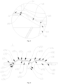
Fig. 1 is a first schematic sectional structural diagram of an indoor unit from a top view according to some examples of the invention; -
Fig. 2 is a second schematic sectional structural diagram of an indoor unit from a top view according to some examples of the invention; -
Fig. 3 is a schematic structural diagram of a portion ofFig. 2 ; -
Fig. 4 is an enlarged diagram of portion A ofFig. 3 ; -
Fig. 5 is an enlarged diagram of portion B ofFig. 3 ; -
Fig. 6 is a schematic sectional structural diagram of a protective net assembly of an indoor unit from a top view according to some examples of the invention, where a protective net body and a flow diversion member are arranged integrally; -
Fig. 7 is a schematic sectional structural diagram of a protective net assembly of an indoor unit from a top view according to some examples of the invention, where a protective net body and a flow diversion member are arranged separately; -
Fig. 8 is an exploded schematic diagram of an indoor unit according to some examples of the invention; -
Fig. 9 is an exploded schematic diagram of a portion of an indoor unit according to some examples of the invention; -
Fig. 10 is a schematic assembly diagram of a protective net assembly and a flow diversion bracket of an indoor unit according to some examples of the invention; -
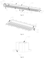
Fig. 11 is a solid schematic structural diagram of a protective net assembly according to some examples of the invention, where a protective net body and a flow diversion member are arranged integrally; -
Fig. 12 is a solid schematic structural diagram of a protective net assembly according to some examples of the invention, where a protective net body and a flow diversion member are arranged separately; -
Fig. 13 is a schematic structural diagram of a protective net inFig. 12 ; and -
Fig. 14 is a schematic structural diagram of a compression cover inFig. 12 . - Some examples of the invention are described in detail below in combination with the drawings. It should be understood that the examples described here are merely used to describe and explain the invention and are not intended to limit the invention.
- In the invention, unless otherwise stated, orientation words used such as "front", "rear", "left" and "right" are defined based on an XY coordinate system in
Figs. 1 and2 . Specifically, direction X refers to a front-rear direction, in which a side indicated by an arrow is front, and the other side is rear. Direction Y refers to a left-right direction, in which a side indicated by an arrow is left, and the other side is right. The up-down direction can refer to a gravity direction of a corresponding component. "Inner" and "outer" refer to an inner contour and an outer contour of each part. "Upstream" and "downstream" are defined based on a flow direction of air. Terms used such as "first" and "second" are to distinguish one element from another, and do not indicate sequence and importance. Furthermore, when the following description relates to the drawings, the same reference numerals in different drawings indicate the same or similar elements, which are not repeated here. - According to some examples of the invention, an indoor unit is provided. With reference to
Figs. 1-3 , the indoor unit includes a cross-flow fan 1, anair duct assembly 2, an air outlet assembly 3 and a protectivenet assembly 4. The cross-flow fan 1 is arranged in theair duct assembly 2, the air outlet assembly 3 is in communication with a downstream portion of theair duct assembly 2, and the protectivenet assembly 4 is arranged between theair duct assembly 2 and the air outlet assembly 3. - Through the above technical solution, in the indoor unit provided in the invention, by arranging the protective
net assembly 4 between theair duct assembly 2 and the air outlet assembly 3, an inner space of the indoor unit can be used to accommodate the protectivenet assembly 4, that is to say, a space between theair duct assembly 2 and the air outlet assembly 3 can be used to accommodate the protectivenet assembly 4. In this way, compared with an example in which the protectivenet assembly 4 is arranged outside the air outlet assembly 3, the protectivenet assembly 4 of the invention can be arranged inside the indoor unit, thus facilitating compact design of the indoor unit. - In some examples of the invention, with reference to
Figs. 1-3 , theair duct assembly 2 may have aguide passage 21. Theguide passage 21 obliquely extends rightwards gradually from rear to front and has anoutlet 22. In this way, air flowing out of the cross-flow fan 1 may flow into theguide passage 21 and then flow rightwards from rear to front to theoutlet 22 gradually. The air outlet assembly 3 may have afirst air outlet 31 and asecond air outlet 32. Thefirst air outlet 31 is arranged on a left side of thesecond air outlet 32. The protectivenet assembly 4 includes aprotective net 41 and aflow diversion member 42. Theprotective net 41 includes a protectivenet body 411 arranged at theoutlet 22. Theflow diversion member 42 is arranged on a front side of the protectivenet body 411 and is located on a downstream portion of the protectivenet body 411. Theflow diversion member 42 is configured to guide air flowing through the flow diversion member to thefirst air outlet 31. Here, theflow diversion member 42 of the invention may implement pre-diversion on air flowing out of the cross-flow fan 1. Specifically, the air flowing out of the cross-flow fan 1 may flow rightwards from rear to front to theoutlet 22 gradually. In this case, a part of the air may pass through the protectivenet body 411 to flow rightwards and forwards and flow out from thesecond air outlet 32, and another part of the air may pass through the protectivenet body 411, flow leftwards and forwards through guide of theflow diversion member 42, and flow out from thefirst air outlet 31. In this case, the pre-diversion on the air by theflow diversion member 42 is beneficial to uniform air outflow of thefirst air outlet 31 and thesecond air outlet 32, that is, substantially the same air volume from thefirst air outlet 31 and thesecond air outlet 32. Thus, the indoor unit of the invention may be configured as a double-outlet-type indoor unit. - In some examples of the invention, with reference to
Figs. 1-3 ,6 and7 , the protectivenet body 411 may cover theoutlet 22 and have a left end, a right end, and a middle end located between the left end and the right end. The middle end may be understood as being at a position bisecting the protectivenet body 411 in a left-right direction. The left end is arranged on a leftmost side of theoutlet 22. The right end is arranged on a rightmost side of theoutlet 22. Theflow diversion member 42 is configured as a flow diversion rib. The flow diversion rib has a firstupstream end 421 and a firstdownstream end 422. The firstupstream end 421 is arranged on a right side of the middle end. Here, since the air flowing out of the cross-flow fan 1 flows rightwards from rear to front gradually to theoutlet 22, the air flowing at a right side of theoutlet 22 has a higher flow velocity, and the air flowing at a left side of theoutlet 22 has a lower flow velocity. Thus, by arranging the firstupstream end 421 at a right side of the middle end, more air flowing at a lower flow velocity may flow to thefirst air outlet 31 through the guide of theflow diversion member 42, and less air flowing at a higher flow velocity may flow rightwards and forwards to thefirst air outlet 31. In this case, such an arrangement can achieve uniform air outflow of thefirst air outlet 31 and thesecond air outlet 32. - In some examples of the invention, with reference to
Figs. 1-3 ,6 and7 , the firstdownstream end 422 may be located on a left side of the firstupstream end 421. In this way, theflow diversion member 42 may conveniently guide the air to flow leftwards. - In some examples of the invention, with reference to
Figs. 1-3 ,6 and7 , the flow diversion rib may be configured to be of an arc-shaped plate structure. Certainly, in other examples, the flow diversion rib may also be configured to be of a flat-plate structure, which is not limited here. - In some examples of the invention, with reference to
Figs. 1-3 ,6 and7 , theprotective net 41 includes a protectivenet body 411. The protectivenet body 411 is configured to be of a grid shape and has avertical rib 4111 and ahorizontal rib 4112 connected together. Thevertical rib 4111 is arranged to obliquely extend rightwards gradually from rear to front. In this way, thevertical rib 4111 may adapt to the air flowing rightwards gradually from rear to front, thus reducing a wind resistance and then reducing a loss of air volume. Here, the protectivenet body 411 may have a plurality ofvertical ribs 4111. Any twovertical ribs 4111 may be parallel to each other, and alternatively, any twovertical ribs 4111 may be arranged at an included angle, which is not limited here. - In some examples of the invention, with reference to
Figs. 1-3 and6-8 , the air outlet assembly 3 may be arranged on a front side of the protectivenet assembly 4. The air outlet assembly 3 includes aflow diversion cone 33 and aswing blade 34 rotatably arranged on theflow diversion cone 33. The protectivenet assembly 4 includes theprotective net 41. Theprotective net 41 is at least partially concave to form anavoidance space 100 for avoiding theswing blade 34. - Through the above technical solution, the air flowing out of the cross-flow fan 1 may enter the air outlet assembly 3 through the protective
net assembly 4. In this case, theswing blade 34 may change the flow direction of the air by rotation, and theflow diversion cone 33 may divert the air. Here, the arrangement of theavoidance space 100 may avoid interference between theswing blade 34 and the protectivenet assembly 4, so as to guarantee respective normal operation of theswing blade 34 and the protectivenet assembly 4, and achieve reasonable design of relative positions of the respective 34 and the protectivenet assembly 4. - According to some examples, when the protective
net assembly 4 is disposed at theoutlet 22 of the indoor unit, theswing blade 34 may be arranged on a front side of the protectivenet body 411. In this case, theswing blade 34 may change the flow direction of the air by rotation, for example, by up-down swing. During rotation of theswing blade 34, the arrangement of theavoidance space 100 may avoid collision between the protectivenet body 411 and theswing blade 34. According to some other examples, a distance between theswing blade 34 and the protectivenet body 411 may be no less than 3 mm-5 mm, so as to absorb an influence caused by assembly errors and manufacturing errors, and further avoid collision between the protectivenet body 411 and theswing blade 34. - In some examples of the invention, with reference to
Figs. 1-3 ,6 and7 , theflow diversion cone 33 may include a firstflow diversion plate 331 and a secondflow diversion plate 332 that are arranged to form an angle. The firstflow diversion plate 331 and the secondflow diversion plate 332 each are provided with theswing blade 34. Theprotective net 41 includes the protectivenet body 411. The protectivenet body 411 has a firstnet body 4113 and a secondnet body 4114 that are connected together. The firstnet body 4113 is provided with anavoidance space 100 for avoiding theswing blade 34 on the firstflow diversion plate 331, and the secondnet body 4114 is provided with anavoidance space 100 for avoiding theswing blade 34 on the secondflow diversion plate 332, that is to say, the firstnet body 4113 and the secondnet body 4114 separately form theavoidance spaces 100. In this way, the firstnet body 4113 and the secondnet body 4114 may avoid thecorresponding swing blades 34 through theavoidance spaces 100 formed by the first net body and the second net body respectively, such that the indoor unit disclosed in the invention is suitable for being configured as a dual-air-outlet indoor unit. For example, the indoor unit may include thefirst air outlet 31 and thesecond air outlet 32. Oneswing blade 34 may be arranged on a rear side or upstream side of each of thefirst air outlet 31 and thesecond air outlet 32. Theswing blades 34 may be partially arranged in thecorresponding avoidance spaces 100. - In some examples of the invention, with reference to
Figs. 1-3 ,6 and7 , the protectivenet body 411 may be configured as M-shaped net by the firstnet body 4113 and the secondnet body 4114 jointly. That is to say, the protectivenet body 411 of the invention may form the twoavoidance spaces 100 by its own M-shape, thus facilitating formation of the twoavoidance spaces 100. - In some examples, with reference to
Figs. 1-3 ,6 and7 , a joint 4115 of the firstnet body 4113 and the secondnet body 4114 is located at a frontmost end of the protectivenet body 411. Here, the joint 4115 can be used to arrange theflow diversion member 42 conveniently. Moreover, since the joint 4115 is located at the frontmost end of theprotective net 41, a flow diversion effect of theflow diversion member 42 can be guaranteed. - In some examples, with reference to
Figs. 1-3 ,6 and7 , the protectivenet body 411 is configured to be of a grid shape and hasvertical ribs 4111 andhorizontal ribs 4112 connected together. The firstnet body 4113 has at least threevertical ribs 4111 spaced in sequence in a left-right direction. In the three adjacentvertical ribs 4111, a frontmost end of thevertical rib 4111 located in the middle is arranged on a front side of frontmost ends of thevertical ribs 4111 located on two sides. In this way, in the example where theflow diversion member 42 is configured to guide the air flowing through the flow diversion member to flow leftwards and forwards, and in a case that the indoor unit has thefirst air outlet 31 and thesecond air outlet 32 located on the right side of thefirst air outlet 31, the middlevertical rib 4111 is arranged closer to a front side or a downstream side, such that the air passing through the middlevertical rib 4111 can flow forwards to theflow diversion member 42. In a case that the frontmost end of the middlevertical rib 4111 is arranged on a rear side of frontmost ends of thevertical ribs 4111 located on two sides, part of the air passing through the middlevertical rib 4111 is prevented from flowing directly to thesecond air outlet 32 without passing through theflow diversion member 42. Thus, the above arrangement is beneficial to uniform air outflow of thefirst air outlet 31 and thesecond air outlet 32. Here, in some examples, with reference toFigs. 1-3 ,6 and7 , the secondnet body 4114 may have onevertical rib 4111, which is not limited here. - In some examples of the invention, with reference to
Figs. 1-3 ,6 and7 , theprotective net 41 includes a protectivenet body 411. The protectivenet body 411 is configured to be of a grid shape and has avertical rib 4111 and ahorizontal rib 4112 connected together. Thevertical rib 4111 may be understood as a rib arranged in an up-down direction. Thevertical rib 4111 has a secondupstream end 41111 and a seconddownstream end 41112. The secondupstream end 41111 may has a width less than that of the seconddownstream end 41112. In this way, the wind resistance can be reduced to reduce the loss of air volume. It should be noted that the width of the secondupstream end 41111 may be understood as a width of a cross section of the secondupstream end 41111. Similarly, the width of the seconddownstream end 41112 may be understood as a width of a cross section of the seconddownstream end 41112. - In some examples of the invention, with reference to
Figs. 1-3 ,6 and7 , thehorizontal rib 4112 has a thirdupstream end 41121 and a thirddownstream end 41122. The thirdupstream end 41121 may have a width less than that of the thirddownstream end 41122. In this way, the wind resistance can be reduced to reduce the loss of air volume. It should be noted that the width of the thirdupstream end 41121 may be understood as a width of a longitudinal section of the thirdupstream end 41121. Similarly, the width of the thirddownstream end 41122 may be understood as a width of a longitudinal section of the thirddownstream end 41122. - In some examples of the invention, with reference to
Figs. 1-3 , the air outlet assembly 3 may include aflow diversion bracket 35. Theflow diversion bracket 35 and theflow diversion cone 33 define a firstair outlet passage 200 and a secondair outlet passage 300. The firstair outlet passage 200 has thefirst air outlet 31. The secondair outlet passage 300 has thesecond air outlet 32. Theswing blade 34 is partially arranged in the firstair outlet passage 200 or the secondair outlet passage 300 correspondingly. Here, the firstair outlet passage 200 and the secondair outlet passage 300 defined by theflow diversion bracket 35 and theflow diversion cone 33 can implement a flow diversion function of the air outlet assembly 3. Specifically, after the air flowing out from the cross-flow fan 1 enters the air outlet assembly 3 through theprotective net 41, the air is divided into the firstair outlet passage 200 and the secondair outlet passage 300 through theflow diversion bracket 35 and theflow diversion cone 33, such that the double-air-outlet design of the indoor unit is achieved. Here, theswing blade 34 is partially arranged in the firstair outlet passage 200 or secondair outlet passage 300 correspondingly, such that theswing blade 34 can conveniently change the flow direction of the air in the firstair outlet passage 200 or secondair outlet passage 300 correspondingly. - In some examples of the invention, with reference to
Figs. 1-3 , the firstflow diversion plate 331 may be configured to define the firstair outlet passage 200, and the secondflow diversion plate 332 may be configured to define the secondair outlet passage 300. The firstflow diversion plate 331 is bent to have afirst plate section 3311 and asecond plate section 3312 that are connected to each other. Thefirst plate section 3311 is connected to the secondflow diversion plate 332. An included angle between thesecond plate section 3312 and the secondflow diversion plate 332 is greater than an included angle between thefirst plate section 3311 and the secondflow diversion plate 332. Theswing blade 34 is connected to thesecond plate section 3312. Here, theswing blade 34 on thesecond plate section 3312 may be farther away from the protective net 41 than thefirst plate section 3311, and since the included angle between thesecond plate section 3312 and the secondflow diversion plate 332 is greater than the included angle between thefirst plate section 3311 and the secondflow diversion plate 332, such an arrangement may also arrange theswing blade 34 on thesecond plate section 3312 closer to the interior of the indoor unit, so as to facilitate the compact design of the indoor unit. - In some examples, with reference to
Figs. 1-3 , theswing blade 34 has arotating shaft 341, and a rotating axis of therotating shaft 341 is horizontally arranged and is perpendicular to thesecond plate section 3312 or the secondflow diversion plate 332 correspondingly. In this way, up-down swing of theswing blade 34 may be implemented. - In some examples of the invention, with reference to
Figs. 1-3 , theflow diversion cone 33 has atip end 333. Thetip end 333 is aligned with the firstdownstream end 422 in a left-right direction. In this way, it is advantageous for theflow diversion cone 33 to divert the air flowing towards the flow diversion cone. - In some examples of the invention, with reference to
Figs. 1-3 and6 , the protectivenet assembly 4 includes aprotective net 41 and aflow diversion member 42. Theprotective net 41 and theflow diversion member 42 may be formed integrally. - Through the above technical solution, in the protective
net assembly 4 provided in the invention, integrated formation of theprotective net 41 and theflow diversion member 42 can reduce the number of parts of the protectivenet assembly 4, so as to simplify assembly steps of the protectivenet assembly 4. Similarly, such the arrangement can also reduce the number of parts of the indoor unit, so as to simplify the assembly steps of the indoor unit. - It should be noted that the protective
net assembly 4 of the invention can be configured as an integrally formed part, which is not limited here. For example, the protectivenet assembly 4 may be integrally molded by extrusion. Here, the protectivenet assembly 4 may be made of a plastic material, which can also reduce manufacturing cost of the protectivenet assembly 4. Compared with the protectivenet assembly 4 made of a metal material, the protectivenet assembly 4 made of a plastic material may also avoid abnormal noise generated by the indoor unit during heating, such that user experience is improved. - It should also be noted that the
flow diversion member 42 of the invention may be understood as a part that may achieve flow division by changing a flow direction of air, which will be described in detail in the following examples of the invention. Moreover, since theprotective net 41 and theflow diversion member 42 are formed integrally, theprotective net 41 and theflow diversion member 42 may be arranged at substantially the same position in the indoor unit. Thus, a flow diversion function of theflow diversion member 42 and a false touch prevention function of the protective net 41 can be advantageously juggled . Here, the false touch prevention function refers to that the protective net 41 can prevent a user from falsely touching the cross-flow fan 1 of the indoor unit. - In some examples of the invention, with reference to
Figs. 1-3 , theprotective net 41 includes a protectivenet body 411. The protectivenet body 411 may have a firstnet body 4113 and a secondnet body 4114 that are connected together. The protectivenet body 411 is configured as an M-shaped net by the firstnet body 4113 and the secondnet body 4114 jointly. Theflow diversion member 42 is connected to a joint 4115 of the firstnet body 4113 and the secondnet body 4114. Here, the joint 4115 can be used to arrange theflow diversion member 42 conveniently. Moreover, since the joint 4115 is located at the frontmost end of theprotective net 41, a flow diversion effect of theflow diversion member 42 can be guaranteed. - In some examples of the invention, with reference to
Figs. 6 and8-10 , theprotective net 41 includes aframe body 43 and a protectivenet body 411 arranged in theframe body 43. Theframe body 43 has anupper frame 431 and alower frame 432. Both theupper frame 431 and thelower frame 432 may havebosses 433. Theflow diversion member 42 is connected to the protectivenet body 411. An upper end and a lower end of theflow diversion member 42 are connected to the correspondingbosses 433 respectively. Here, thebosses 433 may provide a mounting base for the upper end or the lower end of theflow diversion member 42, such that connection strength between thebosses 433 and theprotective net 41 is improved. - In some examples of the invention, with reference to
Fig. 10 , at least one of the twobosses 433 may be further provided with a mountingplatform 434. The mountingplatform 434 is configured to overlap theflow diversion bracket 35 of the indoor unit. In this way, by using overlapping of the mountingplatform 434 and theflow diversion bracket 35, it is convenient to arrange a sealing structure at an overlapping position of the mountingplatform 434 and theflow diversion bracket 35, so as to achieve sealed connection between theupper frame 431 or thelower frame 432 and theflow diversion bracket 35. - In some examples of the invention, with reference to
Figs. 7 ,12 and 13 , the protectivenet assembly 4 includes aprotective net 41 and aflow diversion member 42. Theflow diversion member 42 is detachably connected to theprotective net 41. - Through the above technical solution, in the protective
net assembly 4 provided in the invention, theflow diversion member 42 is configured to be detachably connected to theprotective net 41, that is, theprotective net 41 and theflow diversion member 42 are two separate parts. In this way, compared with a manner that theprotective net 41 and theflow diversion member 42 are formed integrally, a material, shape, etc. of theflow diversion member 42 may be independently designed without considering theprotective net 41, such that theflow diversion member 42 has higher structural strength. Accordingly, in a case that theflow diversion member 42 is connected to theprotective net 41, theflow diversion member 42 is not easily deformed when air flows through theflow diversion member 42, and when the air deforms theprotective net 41, the deformation of theprotective net 41 is unlikely to deform theflow diversion member 42. Thus, the protectivenet assembly 4 of the invention can solve the technical problem that theflow diversion member 42 is likely to deform. - It should be noted that the invention does not limit a specific detachable connection manner between the
flow diversion member 42 and theprotective net 41, which will be described in detail in the following examples of the invention. - In some examples of the invention, the
flow diversion member 42 may be made of a metal material. In this way, compared with theflow diversion member 42 made of a plastic material, theflow diversion member 42 made of a metal material has higher structural strength and is less likely to deform. Here, theflow diversion member 42 may be made of aluminum, which is not limited here. - In some examples of the invention, with reference to
Figs. 7 ,12 and 13 , the protective net 41 may include aframe body 43 and a protectivenet body 411 arranged in theframe body 43. Theflow diversion member 42 is detachably connected to theframe body 43. Theflow diversion member 42 is spaced from the protectivenet body 411. Here, the protectivenet body 411 may be deformed by the air. In this case, since theflow diversion member 42 is spaced from the protectivenet body 411, the deformation of the protectivenet body 411 can be prevented from being transmitted to theflow diversion member 42. Thus, such an arrangement can effectively avoid deformation of theflow diversion member 42, improve stability and reliability of theflow diversion member 42, and avoid abnormal noise caused by the deformation of theflow diversion member 42. - In some examples of the invention, with reference to
Figs. 12-14 , theframe body 43 may have anupper frame 431 and alower frame 432. Both theupper frame 431 and thelower frame 432 have limitingholes 435. An upper end and a lower end of theflow diversion member 42 penetrate the corresponding limitingholes 435 respectively. The lower end of theflow diversion member 42 further extends out of thelower frame 432, such that limiting can be provided for theflow diversion member 42 through the limitingholes 435. The protectivenet assembly 4 may include acompression cover 44. Thecompression cover 44 has a fixinghole 441. The fixinghole 441 is connected to theflow diversion member 42 in an interference fit manner. Thecompression cover 44 is detachably connected to thelower frame 432. In this way, through the interference fit between the fixinghole 441 and theflow diversion member 42, thecompression cover 44 may be fixedly connected to theflow diversion member 42. Through connection between thecompression cover 44 and thelower frame 432, theflow diversion member 42 may be assembled with theprotective net 41, the structure is simple, and operation is convenient. - In some examples of the invention, with reference to
Figs. 12-14 , thelower frame 432 may be provided with a connection column 436. The connection column 436 has a threaded hole in threaded connection to a fastener. Thecompression cover 44 has a throughhole 442 fitted to the connection column 436. In this way, thecompression cover 44 and the connection column 436 may be fixed by the threaded connection between the fastener and the threaded hole, and the reliability is high. Certainly, in other examples of the invention, thecompression cover 44 may also be clamped on thelower frame 432. For example, one of thecompression cover 44 and thelower frame 432 may be provided with a buckle, and the other may be provided with a clamp groove. The detachable connection between thecompression cover 44 and thelower frame 432 is achieved through clamping of the buckle and the clamp groove. - In some examples of the invention, as shown in
Fig. 13 , the limitinghole 435 of theupper frame 431 may be configured as a blind hole. In this way, theupper frame 431 may also provide downward limitation for theflow diversion member 42. - In some examples, with reference to
Figs. 13 and 14 , theupper frame 431 and thelower frame 432 are provided withbosses 433 separately. Thebosses 433 may be provided with limitingholes 435. In this way, thebosses 433 may also provide a mounting base for theflow diversion member 42. Furthermore, compared with increasing a size of theupper frame 431 or thelower frame 432 as a whole, adding thebosses 433 can also reduce a volume and weight of theupper frame 431 or thelower frame 432, which is advantageous to compact design of the indoor unit. - In some examples, with reference to
Figs. 13 and 14 , the limitingholes 435 may further extend into theupper frame 431 or thelower frame 432 correspondingly. In this way, theupper frame 431 and thelower frame 432 may also be used to provide a mounting base for theflow diversion member 42. Moreover, theupper frame 431 or thelower frame 432 may be used to arrange the limitingholes 435, so as to be adapted to theflow diversion members 42 with different sizes. - In some examples, with reference to
Fig. 12 , theboss 433 on theupper frame 431 may be further provided with a mountingplatform 434. The mountingplatform 434 is configured to overlap theflow diversion bracket 35 of the indoor unit. In this way, by using overlapping of the mountingplatform 434 and theflow diversion bracket 35, it is convenient to arrange a sealing structure at an overlapping position of the mountingplatform 434 and theflow diversion bracket 35, so as to achieve sealed connection between theupper frame 431 and theflow diversion bracket 35. - In some examples of the invention, with reference to
Figs. 1-3 and9-13 , the air outlet assembly 3 may include aflow diversion bracket 35. The protective net 41 may include aframe body 43 and a protectivenet body 411 arranged in theframe body 43. Aconnection structure 45 is arranged on theframe body 43. Theframe body 43 is detachably connected to theflow diversion bracket 35 through theconnection structure 45. In this way, theprotective net 41 and theflow diversion bracket 35 may be disassembled and assembled through theconnection structure 45, such that the assembly and disassembly of the protectivenet assembly 4 and theflow diversion bracket 35 is convenient. Here, the invention does not limit a specific structure of theconnection structure 45, which will be described in detail in the following examples of the invention. - In some examples of the invention, with reference to
Figs. 9-13 , theconnection structure 45 may includeslide fasteners 451 arranged on a left side and a right side of theframe body 43 respectively. Theflow diversion bracket 35 hasslide grooves 351 with open upper ends. Theslide fasteners 451 are configured to be inserted into thecorresponding slide grooves 351. Specifically, theslide fasteners 451 may be inserted into thecorresponding slide grooves 351 from top to bottom to implement pre-assembly of theprotective net 41 and theflow diversion bracket 35. - In some examples of the invention, with reference to
Figs. 9-13 , the plurality ofslide fasteners 451 spaced in an up-down direction may be arranged on the left side and the right side of theframe body 43 respectively. Correspondingly, a plurality ofslide grooves 351 spaced in an up-down direction also be arranged on the left side and the right side of theflow diversion bracket 35 respectively, such that the stability of theprotective net 41 and theflow diversion bracket 35 during pre-assembly is improved. - In some examples of the invention, with reference to
Figs. 9-13 , theconnection structure 45 may includeconnection plates 452 arranged on the left side and the right side of theframe body 43 respectively. Theconnection plates 452 have through holes allowing fasteners to penetrate. Theconnection plates 452 are detachably connected to theflow diversion bracket 35 through fasteners. In this way, theprotective net 41 is detachably fixed to theflow diversion bracket 35 through fitting of theconnection plates 452 and the fasteners, such that reliability of connection between theprotective net 41 and theflow diversion bracket 35 is improved. Here, theflow diversion bracket 35 may be provided with a threaded hole fitted to a fastener, which is not limited here. - In some examples of the invention, with reference to
Figs. 9-13 , the plurality ofconnection plates 452 spaced in an up-down direction may be arranged on the left side and the right side of theframe body 43 respectively. In this way, the stability of the connection between theprotective net 41 and theflow diversion bracket 35 may be improved, and connection strength between the protective net and the flow diversion bracket may be improved. - In some examples, with reference to
Figs. 9-13 , any of theconnection plates 452 is arranged between two differentadjacent slide fasteners 451. In this way, fixing points between theprotective net 41 and theflow diversion bracket 35 may be arranged scattered, and insertion points between theprotective net 41 and theflow diversion bracket 35 may be arranged scattered, such that the stability of the connection between theprotective net 41 and theflow diversion bracket 35 is improved. - In some examples of the invention, with reference to
Figs. 1-3 ,8 and9 , theprotective net 41 includes aframe body 43. The protectivenet body 411 is arranged in theframe body 43. Theflow diversion bracket 35 and theair duct assembly 2 may jointly clamp theframe body 43. In this way, it is advantageous for the relative stability of the position of theprotective net 41 and preventing the protective net 41 from shifting and offsetting. - In some examples of the invention, with reference to
Figs. 3, 4 ,6 and7 , the protective net 41 may include aframe body 43. The protectivenet body 411 is arranged in theframe body 43. Theframe body 43 has aleft frame 437 and aright frame 438. Theflow diversion bracket 35 has afirst wall plate 352 for defining the firstair outlet passage 200. Thefirst wall plate 352 has afirst body portion 3521 and afirst protrusion 3522 arranged on thefirst body portion 3521. Thefirst protrusion 3522 and thefirst body portion 3521 define afirst insertion groove 3523. Theleft frame 437 has afirst insertion portion 4371. Thefirst insertion portion 4371 has asecond body portion 4372 and asecond protrusion 4373 arranged on thesecond body portion 4372. Thesecond protrusion 4373 and thesecond body portion 4372 define asecond insertion groove 4374. Thefirst projection 3522 is inserted into thesecond insertion groove 4374 in a shape-fitting manner. Thesecond projection 4373 is inserted into thefirst insertion groove 3523 in a shape-fitting manner. In this way, theleft frame 437 may be inserted into thefirst wall plate 352 in a shape-fitting manner. Accordingly, a sealing structure may be conveniently arranged between theleft frame 437 and thefirst wall plate 352 to prevent air leakage. - In some examples of the invention, with reference to
Figs. 3, 4 ,6 and7 , thefirst protrusion 3522 shares afirst wall surface 3524 with thefirst insertion groove 3523. Thesecond protrusion 4373 shares asecond wall surface 4375 with thesecond insertion groove 4374. Thefirst wall surface 3524 is attached to thesecond wall surface 4375. Thefirst wall surface 3524 obliquely extends leftwards gradually from rear to front. In this way, thefirst wall surface 3524 and thesecond wall surface 4375 are attached to each other to prevent air leakage. Thefirst wall surface 3524 is arranged to obliquely extend leftwards gradually from rear to front to facilitate insertion of theleft frame 437 into theflow diversion bracket 35. - In some examples of the invention, with reference to
Figs. 3 and5-7 , theflow diversion bracket 35 may have asecond wall plate 353 for defining the secondair outlet passage 300. Thesecond wall plate 353 has asecond insertion portion 3531. Theright frame 438 has an L-shapedbent portion 4381. Thesecond insertion portion 3531 is inserted into thebent portion 4381 in a shape-fitting manner. In this way, by using the fitting between thebent portion 4381 and thesecond insertion portion 3531, a sealing structure may be conveniently arranged between theright frame 438 and thesecond wall plate 353 to prevent air leakage. - In some examples of the invention, with reference to
Figs. 1-3 ,4 ,6 and7 , theframe body 43 has aleft frame 437 and aright frame 438. Theair duct assembly 2 has athird wall plate 23 for defining theguide passage 21. Thethird wall plate 23 has athird wall surface 231. Theleft frame 437 has afourth wall surface 4376 attached to thethird wall surface 231. Thefourth wall surface 4376 obliquely extends leftwards gradually from rear to front. In this way, thethird wall surface 231 and thefourth wall surface 4376 are attached to each other to prevent air leakage. Thefourth wall surface 4376 is arranged to obliquely extend leftwards gradually from rear to front to facilitate assembly of theleft frame 437 with theair duct assembly 2. - In some examples of the invention, with reference to
Figs. 1-3 ,5 and7 , theair duct assembly 2 has afourth wall plate 24 for defining theguide passage 21. Thefourth wall plate 24 has afifth wall surface 241. Theright frame 438 has asixth wall surface 4382 attached to thefifth wall surface 241. In this way, thefifth wall surface 241 and thesixth wall surface 4382 are attached to each other to prevent air leakage. - In some examples of the invention, with reference to
Figs. 8-10 , the left side and the right side of theflow diversion bracket 35 may be provided with overlap buckles 354 respectively. The overlap buckles 354 are configured to overlap inoverlap grooves 25 of theair duct assembly 2 of the indoor unit. In this way, pre-assembly of theair duct assembly 2 with theflow diversion bracket 35 may be implemented by overlap of the overlap buckles with theoverlap grooves 25. - In some examples of the invention, with reference to
Figs. 8-10 , the plurality of overlap buckles 354 spaced in an up-down direction may be arranged on the left side and the right side of theflow diversion bracket 35 respectively. Correspondingly, the plurality ofoverlap grooves 25 spaced in an up-down direction may also be arranged on the left side and the right side of theair duct assembly 2 respectively, such that the stability of theflow diversion bracket 35 and theair duct assembly 2 during pre-assembly is improved. - In some examples of the invention, the
flow diversion bracket 35 may further be provided with a connection block. The connection block is configured to be connected to theair duct assembly 2 through a fastener. In this way, theflow diversion bracket 35 is detachably fixed to theair duct assembly 2 through fitting of the connection block and the fastener, such that the reliability of the connection between theflow diversion bracket 35 and theair duct assembly 2 is improved. Here, theair duct assembly 2 may be provided with a threaded hole fitted to a fastener, which is not limited here. - In the below, a specific working process of the indoor unit will be described in detail in combination with the above specific examples in the invention. With reference to
Figs. 1-3 , firstly, with rotation of the cross-flow fan 1, air may enter theguide passage 21, and flow out of theoutlet 22 rightwards from rear to front gradually through guide of theguide passage 21. In this case, a part of the air may pass through the protectivenet body 411 to flow rightwards and forwards and flow out from thesecond air outlet 32, and another part of the air may pass through the protectivenet body 411, flow leftwards and forwards through guide of theflow diversion member 42, and flow out from thefirst air outlet 31, such that the double-air-outlet design of the indoor unit is achieved. In this process, since the firstupstream end 421 of the flow diversion rib is arranged close to the right, more air flowing at a lower flow velocity flows to thefirst air outlet 31 through the guide of theflow diversion member 42, and less air flowing at a higher flow velocity flows rightwards and forwards to thefirst air outlet 31. In this case, such an arrangement can achieve uniform air outflow of thefirst air outlet 31 and thesecond air outlet 32. - In the below, a specific working process of the indoor unit will be described in detail in combination with the above specific examples in the invention. Here, the indoor unit may further include a
front housing 5 and a rear housing 6. During assembly, with reference toFigs. 1 ,8 and9 , the cross-flow fan 1 and theair duct assembly 2 may be mounted on the rear housing 6 first, and then theflow diversion cone 33 and theflow diversion bracket 35 may be connected together. After that, the protectivenet assembly 4 is assembled to theflow diversion bracket 35. Specifically, theslide fasteners 451 may be inserted into theslide grooves 351, and theconnection plates 452 may be connected to theflow diversion bracket 35 through fasteners. After that, theflow diversion cone 33, theflow diversion bracket 35 and the protectivenet assembly 4 are mounted on theair duct assembly 2 as a whole. In this process, theflow diversion bracket 35 may be connected to theair duct assembly 2. Specifically, theoverlap buckle 354 overlaps theoverlap groove 25, and the connection block is connected to theair duct assembly 2 through a fastener. Finally, thefront housing 5 is assembled to the rear housing 6, and assembly of the indoor unit is completed. - According to a second aspect of the invention, an air conditioner is provided. The air conditioner includes the above indoor unit. The air conditioner has all the beneficial effects of the indoor unit described above, which are not limited in the invention. Certainly, the air conditioner of the invention further includes an outdoor unit, and a specific structure of the outdoor unit is not limited here.
Claims (15)
- An indoor unit, comprising:a cross-flow fan (1);an air duct assembly (2);an air outlet assembly (3) ; anda protective net assembly (4), wherein the cross-flow fan (1) is arranged in the air duct assembly (2), the air outlet assembly (3) is in communication with a downstream portion of the air duct assembly (2), and the protective net assembly (4) is arranged between the air duct assembly (2) and the air outlet assembly (3).
- The indoor unit according to claim 1, whereinthe air duct assembly (2) has a guide passage (21), and the guide passage (21) obliquely extends rightwards gradually from rear to front and has an outlet (22);the air outlet assembly (3) has a first air outlet (31) and a second air outlet (32), and the first air outlet (31) is arranged on a left side of the second air outlet (32); andthe protective net assembly (4) comprises a protective net (41) and a flow diversion member (42), the protective net (41) comprises a protective net body (411) arranged at the outlet (22), the flow diversion member (42) is arranged on a front side of the protective net body (411) and is located on a downstream portion of the protective net body (411), and the flow diversion (42) member is configured to guide air flowing through the flow diversion member to the first air outlet (31).
- The indoor unit according to claim 2, wherein the protective net body (411) covers the outlet (22) and has a left end, a right end, and a middle end located between the left end and the right end, the left end is arranged on a leftmost side of the outlet (22), and the right end is arranged on a rightmost side of the outlet (22); andthe flow diversion member (42) is configured as a flow diversion rib, the flow diversion rib has a first upstream end (421) and a first downstream end (422), and the first upstream end (421) is arranged on a right side of the middle end;optionally, wherein the first downstream end (422) is located on a left side of the first upstream end (421).
- The indoor unit according to claim 3, wherein the flow diversion rib is configured to be of an arc-shaped plate structure.
- The indoor unit according to any one of claims 2-4, wherein the protective net body (411) is configured to be of a grid shape and has a vertical rib (4111) and a horizontal rib (4112) connected together, and the vertical rib (4111) is arranged to obliquely extend rightwards gradually from rear to front.
- The indoor unit according to any one of claims 1-5, wherein the air outlet assembly (3) is arranged on a front side of the protective net assembly (4), the air outlet assembly (3) comprises a flow diversion cone (33) and a swing blade (34) rotatably arranged on the flow diversion cone (33), the protective net assembly (4) comprises a protective net (41), and the protective net (41) is at least partially concave to form an avoidance space (100) for avoiding the swing blade (34).
- The indoor unit according to claim 6, wherein the flow diversion cone (33) comprises a first flow diversion plate (331) and a second flow diversion plate (332) that are arranged to form an angle, and the first flow diversion plate (331) and the second flow diversion plate (332) each are provided with the swing blade (34); andthe protective net (41) comprises a protective net body (411), the protective net body (411) has a first net body (4113) and a second net body (4114) that are connected together, the first net body (4113) is provided with an avoidance space (100) for avoiding the swing blade (34) on the first flow diversion plate (331), and the second net body (4114) is provided with an avoidance space (100) for avoiding the swing blade (34) on the second flow diversion plate (332);optionally, wherein the protective net body (411) is configured as an M-shaped net by the first net body (4113) and the second net body (4114) jointly.
- The indoor unit according to claim 7, wherein the air outlet assembly (3) comprises a flow diversion bracket (35), the flow diversion bracket (35) and the flow diversion cone (33) define a first air outlet passage (200) and a second air outlet passage (300), the first air outlet passage (200) has a first air outlet (31), the second air outlet passage (300) has a second air outlet (32), and the swing blade (34) is partially arranged in the first air outlet passage (200) or the second air outlet passage (300) correspondingly.
- The indoor unit according to any one of claims 1-8, wherein the protective net assembly (4) comprises a protective net (41) and a flow diversion member (42), and the protective net (41) and the flow diversion member (42) are integrally formed;
optionally, wherein the protective net assembly (4) is made of a plastic material. - The indoor unit according to claim 9, wherein the protective net (41) comprises a protective net body (411), the protective net body (411) has a first net body (4113) and a second net body (4114) that are connected together, the protective net body (411) is configured as an M-shaped net by the first net body (4113) and the second net body (4114) jointly, and the flow diversion member (42) is connected to a joint (4115) of the first net body (4113) and the second net body (4114).
- The indoor unit according to any one of claims 1-8, wherein the protective net assembly (4) comprises a protective net (41) and a flow diversion member (42), and the flow diversion member (42) is detachably connected to the protective net (41);
optionally, wherein the flow diversion member (42) is made of a metal material. - The indoor unit according to claim 11, wherein the protective net (41) comprises a frame body (43) and a protective net body (411) arranged in the frame body (43), the flow diversion member (42) is detachably connected to the frame body (43), and the flow diversion member (42) is spaced from the protective net body (411).
- The indoor unit according to claim 12, wherein the frame body (43) has an upper frame (431) and a lower frame (432), both the upper frame (431) and the lower frame (432) have limiting holes (435), an upper end and a lower end of the flow diversion member (42) penetrate corresponding limiting holes (435) respectively, and the lower end of the flow diversion member (42) extends out of the lower frame (432); and
the protective net assembly (4) comprises a compression cover (44), the compression cover (44) has a fixing hole (441), the fixing hole (441) is connected to the flow diversion member (42) in an interference fit manner, and the compression cover (44) is detachably connected to the lower frame (432). - The indoor unit according to claim 13, wherein the lower frame (432) is provided with a connection column (436), the connection column (436) has a threaded hole in threaded connection to a fastener, and the compression cover (44) has a through hole (442) fitted to the connection column (436);
optionally, wherein the limiting hole (435) of the upper frame (431) is configured as a blind hole. - An air conditioner comprising an indoor unit, the indoor unit comprising a cross-flow fan (1), an air duct assembly (2), an air outlet assembly (3) and a protective net assembly (4), wherein the cross-flow fan (1) is arranged in the air duct assembly (2), the air outlet assembly (3) is in communication with a downstream portion of the air duct assembly (2), and the protective net assembly (4) is arranged between the air duct assembly (2) and the air outlet assembly (3).
Applications Claiming Priority (1)
| Application Number | Priority Date | Filing Date | Title |
|---|---|---|---|
| CN202311536301.1A CN117450572A (en) | 2023-11-15 | 2023-11-15 | Indoor units and air conditioners |
Publications (1)
| Publication Number | Publication Date |
|---|---|
| EP4556801A1 true EP4556801A1 (en) | 2025-05-21 |
Family
ID=89581728
Family Applications (1)
| Application Number | Title | Priority Date | Filing Date |
|---|---|---|---|
| EP24213295.9A Pending EP4556801A1 (en) | 2023-11-15 | 2024-11-15 | Indoor unit and air conditioner |
Country Status (3)
| Country | Link |
|---|---|
| US (1) | US20250155156A1 (en) |
| EP (1) | EP4556801A1 (en) |
| CN (1) | CN117450572A (en) |
Citations (5)
| Publication number | Priority date | Publication date | Assignee | Title |
|---|---|---|---|---|
| CN207132446U (en) * | 2017-06-23 | 2018-03-23 | 大金工业株式会社 | Indoor apparatus of air conditioner |
| WO2020155356A1 (en) * | 2019-02-03 | 2020-08-06 | 广东美的制冷设备有限公司 | Panel assembly of air conditioner, and window-type air conditioner |
| CN112484156A (en) * | 2019-09-11 | 2021-03-12 | 广东美的制冷设备有限公司 | Floor type air conditioner indoor unit and air conditioner |
| CN216281701U (en) * | 2021-03-17 | 2022-04-12 | 海信(山东)空调有限公司 | Indoor unit of air conditioner |
| CN116358147A (en) * | 2021-12-21 | 2023-06-30 | 宁波奥克斯电气股份有限公司 | An air conditioner finger guard and an air conditioner |
-
2023
- 2023-11-15 CN CN202311536301.1A patent/CN117450572A/en active Pending
-
2024
- 2024-11-13 US US18/946,606 patent/US20250155156A1/en active Pending
- 2024-11-15 EP EP24213295.9A patent/EP4556801A1/en active Pending
Patent Citations (5)
| Publication number | Priority date | Publication date | Assignee | Title |
|---|---|---|---|---|
| CN207132446U (en) * | 2017-06-23 | 2018-03-23 | 大金工业株式会社 | Indoor apparatus of air conditioner |
| WO2020155356A1 (en) * | 2019-02-03 | 2020-08-06 | 广东美的制冷设备有限公司 | Panel assembly of air conditioner, and window-type air conditioner |
| CN112484156A (en) * | 2019-09-11 | 2021-03-12 | 广东美的制冷设备有限公司 | Floor type air conditioner indoor unit and air conditioner |
| CN216281701U (en) * | 2021-03-17 | 2022-04-12 | 海信(山东)空调有限公司 | Indoor unit of air conditioner |
| CN116358147A (en) * | 2021-12-21 | 2023-06-30 | 宁波奥克斯电气股份有限公司 | An air conditioner finger guard and an air conditioner |
Also Published As
| Publication number | Publication date |
|---|---|
| CN117450572A (en) | 2024-01-26 |
| US20250155156A1 (en) | 2025-05-15 |
Similar Documents
| Publication | Publication Date | Title |
|---|---|---|
| EP2169327B1 (en) | Air delivery unit | |
| KR100408598B1 (en) | Cross blower | |
| CN210399178U (en) | Cabinet air conditioner indoor unit | |
| CN112026935B (en) | Front-end structure | |
| EP4556801A1 (en) | Indoor unit and air conditioner | |
| CN209877129U (en) | Cabinet type air conditioner indoor unit | |
| CN210118955U (en) | Air deflector assembly of air conditioner and air conditioner thereof | |
| CN116906979B (en) | Return air frame structure and air conditioning equipment | |
| CN210220180U (en) | Middle frame structure and air conditioner | |
| CN213713225U (en) | Air conditioner indoor unit and air conditioner | |
| CN224135967U (en) | Air duct structure and air conditioner | |
| EP4317809A1 (en) | Wall-mounted air conditioner | |
| CN215863768U (en) | Air outlet net cover and air conditioner | |
| CN222459768U (en) | Finger guard assembly, indoor unit and air conditioner | |
| CN222103894U (en) | Finger guard assembly, indoor unit and air conditioner | |
| CN222925573U (en) | Fume exhaust fan | |
| US11679664B2 (en) | Ventilation device of a motor vehicle | |
| JP2018161983A (en) | Front body structure of vehicle | |
| CN224151147U (en) | Shell assembly and air conditioner | |
| JP2017089912A (en) | Water heater | |
| EP4317829A1 (en) | Wall-mounted air conditioner | |
| CN115528853B (en) | Cold air hood | |
| CN222210569U (en) | Air conditioner outdoor unit and air conditioner | |
| CN117419451A (en) | Air-out structure, indoor unit and air conditioner | |
| CN220038565U (en) | Fume exhauster |
Legal Events
| Date | Code | Title | Description |
|---|---|---|---|
| PUAI | Public reference made under article 153(3) epc to a published international application that has entered the european phase |
Free format text: ORIGINAL CODE: 0009012 |
|
| STAA | Information on the status of an ep patent application or granted ep patent |
Free format text: STATUS: REQUEST FOR EXAMINATION WAS MADE |
|
| 17P | Request for examination filed |
Effective date: 20241115 |
|
| AK | Designated contracting states |
Kind code of ref document: A1 Designated state(s): AL AT BE BG CH CY CZ DE DK EE ES FI FR GB GR HR HU IE IS IT LI LT LU LV MC ME MK MT NL NO PL PT RO RS SE SI SK SM TR |