EP4556740A1 - Active brake dust particle filter system - Google Patents
Active brake dust particle filter system Download PDFInfo
- Publication number
- EP4556740A1 EP4556740A1 EP23209950.7A EP23209950A EP4556740A1 EP 4556740 A1 EP4556740 A1 EP 4556740A1 EP 23209950 A EP23209950 A EP 23209950A EP 4556740 A1 EP4556740 A1 EP 4556740A1
- Authority
- EP
- European Patent Office
- Prior art keywords
- airflow
- water
- drainage
- assembly
- drainage outlet
- Prior art date
- Legal status (The legal status is an assumption and is not a legal conclusion. Google has not performed a legal analysis and makes no representation as to the accuracy of the status listed.)
- Pending
Links
Images




Classifications
-
- F—MECHANICAL ENGINEERING; LIGHTING; HEATING; WEAPONS; BLASTING
- F16—ENGINEERING ELEMENTS AND UNITS; GENERAL MEASURES FOR PRODUCING AND MAINTAINING EFFECTIVE FUNCTIONING OF MACHINES OR INSTALLATIONS; THERMAL INSULATION IN GENERAL
- F16D—COUPLINGS FOR TRANSMITTING ROTATION; CLUTCHES; BRAKES
- F16D65/00—Parts or details
- F16D65/0031—Devices for retaining friction material debris, e.g. dust collectors or filters
Definitions
- the invention relates to an active brake dust particle filter system including a brake assembly including at least one brake disc, and an airflow generating assembly including an airflow generator configured to generate an airflow, and at least one collector arranged at least partially surrounding the brake disc configured to collect brake dust particles from an ambient air of the brake disc via the airflow, and at least one pipe connecting the airflow generator and the collector for conducting the airflow from the collector towards the airflow generator.
- Such active brake dust particle filter systems are per se known in the art. They are advantageously used with brake assemblies in both mobile and stationary applications.
- Mobile applications include, for example, passenger or goods vehicles and rail vehicles.
- Stationary applications include, for example, brake assemblies used in wind turbines.
- Brake dust particles are commonly produced upon actuation of the brake assembly. Typically, brake abrasion due to friction between a brake pad and the brake disc of the brake assembly results in the production of said brake dust particles.
- the brake dust particles constitute a (fine) dust load in the ambient air of the brake disc. Such (fine) dust load of the ambient air is harmful to humans and nature. It should therefore not escape into the environment.
- the airflow generating assembly includes at least one collector arranged at least partially surrounding the brake disc.
- said collector ambient air of the brake disc containing brake dust particles accumulates. Said ambient air containing brake dust particles is then sucked from the collector towards the airflow generator via the airflow.
- the airflow is generated and maintained by the airflow generator.
- the airflow is led through the pipe which fluidically connects the collector and the airflow generator.
- the airflow containing ambient air loaded with brake dust particles may then filtered and cleaned from the harmful brake dust particles by means of a filter element.
- Said filter element is advantageously arranged at or in the vicinity of the airflow generator.
- the water separating assembly can include an inertial separator configured to inertially separate the water from the airflow.
- the water separating assembly operates as follows.
- the at least one baffle element is used to deflect the airflow from its original flow direction. However, due to its inertia, the water dragged along in the airflow can then no longer follow the deflected airflow.
- the water is separated from the airflow. It accumulates in the airflow generating assembly.
- said accumulated water is then drained from the airflow generating assembly by means of the water drainage assembly.
- the airflow generating assembly is therefore equipped to be reliably operated in humid or wet conditions. Any water initially present in the airflow is separated therefrom before the airflow reaches the airflow generator. Said water is hence neither capable of reducing the filter performance of the filter element or decrease its service lifetime nor of damaging the airflow generator or impairing its performance or suction capacity.
- the water separating assembly is arranged directly on the collector and fluidically downstream with respect to the airflow.
- the water separating assembly includes at least two baffle elements arranged substantially parallel and opposite to each other as well as arranged substantially perpendicular to the airflow.
- the at least two baffle elements include a first baffle element and a second baffle element.
- the first baffle element may be a first baffle plate.
- the second baffle element may be a second baffle plate.
- the first baffle element and the second baffle element are arranged within a baffle duct.
- the baffle duct is included in the water separating assembly.
- the baffle duct is arranged to receive the airflow and advance it further downstream towards the airflow generator.
- the baffle duct includes a central axis.
- the central axis of the baffle duct is substantially parallel to a lateral axis of the brake disc.
- the first baffle element is arranged substantially perpendicular to the central axis within the baffle duct.
- the first baffle element provides a deflection angle for the airflow of less than 180°, preferably 90° or less.
- the second baffle element is arranged substantially parallel to the first baffle element.
- the second baffle element is arranged opposite the first baffle element.
- the second baffle element is arranged on a second wall of the baffle duct.
- the second wall of the baffle duct is substantially opposite the first wall of the baffle duct in a direction perpendicular to the central axis of the baffle duct.
- the second baffle element provides a deflection angle for the airflow of less than 180°, preferably 90° or less.
- the first baffle element and the second baffle element are spaced apart from each other by a predetermined distance.
- the first baffle element separates a first amount of dragged along water from the airflow.
- the second baffle element separates a second amount of dragged along water from the airflow. In this way, the airflow is gradually freed from the dragged along water. Any water not yet separated by means of the first baffle element may be separated by means of the second baffle element. It is to be understood that any number of baffle elements can be employed in this process.
- the number of two baffle elements is merely exemplary. An array with any number of baffle elements can be employed additionally or instead.
- the water separating assembly includes at least one baffle element formed as a chamber-like protrusion, and at least one other baffle element extending at least in a section into the chamber-like protrusion.
- the chamber-like protrusion defines a receiving volume for the airflow.
- the chamber-like protrusion is arranged within the baffle duct.
- the chamber-like protrusion extends substantially perpendicular to the central axis of the baffle duct.
- the chamber-like- protrusion extends beyond an outer circumference of the baffle duct at least in sections of the baffle duct.
- the chamber-like protrusion is arranged on the first wall of the baffle duct.
- the chamber-like protrusion provides a deflection angle for the airflow of 180°, preferably 90° or less.
- the other baffle element extends at least in sections into the chamber-like protrusion. To this end, the other baffle element is arranged opposite the chamber-like protrusion.
- the other baffle element is arranged on the second wall of the baffle duct.
- the other baffle element may be centered with respect to a diameter of the chamber-like protrusion seen in the direction of the central axis of the baffle duct.
- the other baffle element provides a deflection angle for the airflow of less than 180°, preferably 90° or less.
- Downstream with respect to the airflow of the chamber-like protrusion and the other baffle element a water collecting reservoir may be arranged.
- the water collecting reservoir serves to collect the water separated by means of the water separating assembly.
- the water collecting reservoir may be formed as a protrusion within the baffle duct.
- the water collecting reservoir includes a reservoir opening arranged for discharging the separated water collected inside the water collecting reservoir.
- the separated water can be discharged from the water collecting reservoir into an ambient space of the water separating assembly.
- a filter element can be arranged fluidically between the reservoir opening and the ambient space of the water separating assembly. The filter element serves to filter any brake dust particles out of the discharged airflow. The filter element may also serve to filter any dirt particles out of the discharged separated water.
- the reservoir opening may be identical to the drainage outlet of the water drainage assembly.
- the water drainage assembly is arranged directly on the water separating assembly and is for establishing a fluidic connection for the separated water between an interior of the water separating assembly and an ambient space of the water separating assembly.
- the separated water can be discharged from the active brake dust particle filter system directly at the location of the collector, more specifically in the vicinity of the brake disc.
- any transport of the water dragged along in the airflow through the active brake dust particle filter system is avoided. No additional components for such a transport need be provided. Constructional space is saved. The risk of malfunction of the transport of the water through the active brake dust particle filter system is avoided.
- the reservoir opening of the water collecting reservoir may be identical to the drainage outlet of the water drainage assembly.
- the water drainage assembly is arranged on the pipe and is for establishing a fluidic connection for the separated water between an interior of the pipe and an ambient space of the pipe, via the drainage outlet.
- the separated water is led away from the water separating assembly, more specifically the brake disc. It is dragged along with the airflow into the suction collecting pipe and away from the brake assembly.
- the water drainage assembly is arranged on the pipe. At this location the drainage outlet serves to discharge the separated water into the ambient space of the pipe.
- any separated water is led away from both the water separating assembly as well as the brake assembly. Thus, any negative impact of the separated water on these or neighboring constructional elements can be avoided.
- the separated water may be discharged at a location where it cannot damage any components of the active brake dust particle filter system.
- the water drainage assembly further includes a filter element for filtering the airflow, the filter element being arranged fluidically between the drainage outlet and the ambient space of the pipe.
- the filter element is preferably provided in the form of a filter paper, a filter fabric, filter scrim or filter fleece.
- the filter element can be produced in a spunbonded or meltblown process or include such a fiber layer applied to a nonwoven or cellulose carrier.
- the filter element may be felted or needled.
- the filter element may have natural fibers, such as cellulose or cotton, or synthetic fibers, for example polyester, polyvinylsulfit or polytetrafluoroethylene.
- the filter element may be a sinter filter.
- the sinter filter can be produced by means of sintering polytetrafluoroethylene, polyethylene or sinter metal. Any other filter elements known per se in the art can also be employed.
- the filter element serves to filter brake dust particles out of the airflow.
- the filter element serves to filter any dirt or dirt particles out of the separated water in the airflow. The discharge of brake dust particles into the environment is thus avoided.
- the filter element is formed in one piece with the pipe or is attached fluid-tight onto the drainage outlet, particularly by means of molding, clipping, pressing, spraying, gluing, screwing or welding.
- the filter element may, for example, be pushed onto the pipe and placed such that it covers the drainage outlet.
- the filter element thus acts as a sleeve arranged on the pipe.
- the filter element can be held in place with clamps or other mechanical fastening elements known in the art.
- the pipe itself can be made out of suitable filter element material at the location of the drainage outlet, presenting a one-piece design. It is to be understood that any other means of attaching the filter element to the pipe may be equally advantageously employed.
- the water drainage assembly further includes a drainage outlet protection cover for protecting the drainage outlet against environmental impacts, the drainage outlet protection cover including one or more drainage grooves and being fitted onto the drainage outlet.
- the drainage outlet protection cover can be provided additionally to the filter element. It is particularly advantageous in a case in which the filter element is susceptible of being damaged by stone chipping or other debris striking against the water drainage assembly and the filter element.
- the drainage outlet protection cover includes at least one drainage groove.
- the drainage outlet protection cover may include a plurality of drainage grooves. The drainage groove serves to establish a passageway for the airflow through the drainage outlet, the filter element and the drainage outlet protection cover. In this way, an unobstructed drainage via the water drainage assembly is ensured.
- the drainage outlet is located on the pipe at the fluidically lowest point of the pipe in terms of height.
- the separated water is discharged at the fluidically lowest point of the pipe.
- the separated water may thus not accumulate inside the active brake dust particle filter system where it might clog the airflow cross-section and be sucked into the airflow generator and damage the latter.
- the drainage outlet may be located at the same height as the brake assembly.
- a siphon may be provided for collecting and ultimately discharging the separated water into the ambient space.
- the water drainage assembly is arranged on the airflow generator and is for establishing a fluidic connection for the separated water between an interior of the airflow generator and an ambient space of the airflow generator, via the at least one drainage outlet.
- the water drainage assembly further includes a filter element for filtering the airflow, the filter element being arranged fluidically between the at least one drainage outlet and the ambient space of the airflow generator.
- the filter element is formed in one piece with the airflow generator or is attached fluid-tight onto the at least one drainage outlet, particularly by means of molding, clipping, pressing, spraying, gluing, screwing or welding.
- the water drainage assembly further includes a drainage outlet protection cover for protecting the at least one drainage outlet against environmental impacts, the drainage outlet protection cover including one or more drainage grooves and being fitted onto the at least one drainage outlet.
- the drainage outlet is located on the airflow generator at the fluidically lowest point of the airflow generator in terms of height.
- Figure 1 shows an active brake dust particle filter system 1.
- the active brake dust particle filter system 1 includes two identical brake assemblies 2 in the present embodiment. It also includes an airflow generating assembly 3.
- Each brake assembly 2 includes a brake disc 4.
- the airflow generating assembly 3 is included of a plurality of different units. Firstly, the airflow generating assembly 3 includes an airflow generator 5. Secondly, the airflow generating assembly 3 includes two collectors 6 or collecting conduits in the present embodiment. The collectors 6 are arranged at least partially around the brake discs 4. Thirdly, the airflow generating assembly 3 also includes two pipes 7 in the present embodiment.
- the operating principle of the airflow generating assembly 3 is as follows. Upon actuation of the brake assembly 2 a brake pad 8 comes into contact with the brake disc 4. This initiates a braking action. During contact of the brake pad 8 with the brake disc 4 abrasion of the brake pad 8 occurs. This abrasion produces brake dust particles in the ambient air of the brake disc 4.
- the brake dust particles are collected within the suction collector 6.
- an airflow is then generated. This is achieved by means of the airflow generator 5.
- the airflow generator 5 establishes, maintains and drives the airflow.
- the airflow containing the brake dust particles is then sucked from the collector 6 through the pipes 7 towards the airflow generator 5.
- the airflow may be subjected to a filter element in order to filter the brake dust particles from the airflow.
- Figure 2 shows a detailed view of the brake assembly 2 with the collector 6.
- Figure 3 gives a detailed top view of Figure 2 including a section line A-A.
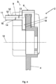
- Figure 4 shows a sectional view of the brake assembly 2 and a first embodiment of the airflow generating assembly 3 of figure 1 along the section line A-A of Figure 3 with the additional features.
- the airflow generating assembly 3 further includes a water separating assembly 9.
- the water separating assembly 9 is arranged fluidically directly adjacent to the collector 6.
- the water separating assembly 9 is fluidically directly connected to the collector 6 in a direction downstream with respect to the airflow.
- the water separating assembly 9 includes a baffle duct 10.
- the baffle duct 10 includes a central axis 11 of the baffle duct 10.
- the central axis 11 of the baffle duct 10 runs substantially parallel to a lateral axis 12 of the brake disc 4.
- the baffle duct 10 includes a first baffle element 13.
- the baffle duct 10 includes a second baffle element 14.
- the first baffle element 13 is arranged on a first wall 15 of the baffle duct 10.
- the second baffle element 14 is arranged on a second wall 16 of the baffle duct 10.
- the first baffle element 13 and the second baffle element 14 are arranged on opposite sides in the baffle duct 10.
- the first baffle element 13 and the second baffle element 14 extend substantially parallel to each other. They extend perpendicularly to the central axis 11 of the baffle duct 10.
- the first baffle element 13 provides a deflection angle for the airflow of 90°.
- the second baffle element 14 provides a deflection angle for the airflow of 90°.
- the water separating assembly 9 serves as an inertial separator. The water dragged along in the airflow cannot follow the deflection and re-direction of the latter and is therefore separated from the airflow.
- This embodiment is only an example, and the first baffle element 13 and the second baffle element 14 may be substantially perpendicular to each other, may have different angles with respect to the central axis 11, and may even have a twist or screw geometry.
- the thusly separated water can then be drained from the airflow generating assembly 3.
- a water drainage assembly 17 is provided.
- the water drainage assembly 17 includes at least one drainage outlet 18.
- the separated water accumulates in the water drainage assembly 17 and exits the airflow generating assembly 3 via the drainage outlet 18 into the ambient space of the brake assembly 2. Negative impacts of water within the airflow generating assembly 3 can thus be eliminated.
- FIG 5 shows a sectional view of the brake assembly 2 and a second embodiment of the airflow generating assembly 3 of Figure 3 along the section line A-A.
- the first baffle element 13 is formed as a chamber-like protrusion within the first wall 15 of the baffle duct 10.
- the chamber-like protrusion defines a receiving volume 19 for the airflow.
- the airflow is deflected at a deflection angle of 180°.
- the second baffle element 14 is arranged at the second wall 16 of the baffle duct 10. It is oriented substantially perpendicular to the central axis 11 of the baffle duct 10.
- the second baffle element 14 is formed as a baffle plate.
- a drainage outlet protection cover 22 is provided in this embodiment.
- the drainage outlet protection cover 22 is particularly advantageous in a case in which the filter element 21 is susceptible of being damaged by stone chipping or other debris striking against the water drainage assembly 17 and the filter element 21.
- the drainage outlet protection cover 22 includes a plurality of drainage grooves 23.
- the drainage grooves 23 serve to establish a passageway for the airflow through the drainage outlet 18, the filter element 21 and the drainage outlet protection cover 22. In this way, an unobstructed drainage via the water drainage assembly 17 is ensured.
- the drainage outlet protection cover 22 can be, e.g., glued, welded or screwed onto the pipe 7.
- the drainage outlet 18 is advantageously located on the pipe 7 at the fluidically lowest point of the pipe 7. This is best seen in Figure 1 .
- the drainage outlet 18 may be located on the pipe 7 at any fluidically low point of the pipe 7, for example, local to the airflow generator 5.
- FIGS 7 and 8 show a water drainage assembly 24 according to a different or additional embodiment.
- the water drainage assembly 17 is arranged on the airflow generator 5.
- the drainage outlet 18 extends substantially parallel to a longitudinal direction of a bottom surface of the airflow generator 5 at least in a section of the latter, and extends between the pipes 7.
- the filter element 21 is provided fluidically between the drainage outlet 18 and an ambient space of the airflow generator 5.
- the filter element 21 serves to filter brake dust particles out of the airflow through the airflow generator 5. It also may serve to filter out dirt or dirt particles out of the separated water being discharged through the drainage outlet 18.
- the drainage outlet protection cover 22 is provided in this embodiment.
- the drainage outlet protection cover 22 is particularly advantageous in a case in which the filter element 21 is susceptible of being damaged by stone chipping or other debris striking against the water drainage assembly 17 and the filter element 21.
- the drainage outlet protection cover 22 includes the plurality of drainage grooves 23.
- the drainage grooves 23 serve to establish a passageway for the airflow through the drainage outlet 18, the filter element 21 and the drainage outlet protection cover 22. In this way, an unobstructed drainage via the water drainage assembly 17 is ensured.
- the drainage outlet protection cover 22 can be, e.g., glued, welded or screwed onto the airflow generator 5.
- the drainage outlet 18 is advantageously located on the airflow generator 5 at the fluidically lowest point of the airflow generator 5.
Landscapes
- Engineering & Computer Science (AREA)
- General Engineering & Computer Science (AREA)
- Mechanical Engineering (AREA)
- Braking Arrangements (AREA)
Abstract
Description
- The invention relates to an active brake dust particle filter system including a brake assembly including at least one brake disc, and an airflow generating assembly including an airflow generator configured to generate an airflow, and at least one collector arranged at least partially surrounding the brake disc configured to collect brake dust particles from an ambient air of the brake disc via the airflow, and at least one pipe connecting the airflow generator and the collector for conducting the airflow from the collector towards the airflow generator.
- Such active brake dust particle filter systems are per se known in the art. They are advantageously used with brake assemblies in both mobile and stationary applications. Mobile applications include, for example, passenger or goods vehicles and rail vehicles. Stationary applications include, for example, brake assemblies used in wind turbines.
- Brake dust particles are commonly produced upon actuation of the brake assembly. Typically, brake abrasion due to friction between a brake pad and the brake disc of the brake assembly results in the production of said brake dust particles. The brake dust particles constitute a (fine) dust load in the ambient air of the brake disc. Such (fine) dust load of the ambient air is harmful to humans and nature. It should therefore not escape into the environment.
- To this end, the airflow generating assembly is provided. It includes at least one collector arranged at least partially surrounding the brake disc. In said collector ambient air of the brake disc containing brake dust particles accumulates. Said ambient air containing brake dust particles is then sucked from the collector towards the airflow generator via the airflow. The airflow is generated and maintained by the airflow generator. The airflow is led through the pipe which fluidically connects the collector and the airflow generator. The airflow containing ambient air loaded with brake dust particles may then filtered and cleaned from the harmful brake dust particles by means of a filter element. Said filter element is advantageously arranged at or in the vicinity of the airflow generator.
- However, for example in mobile applications such as passenger vehicles, goods vehicles or rail vehicles, it is frequently encountered that said vehicles are operated in humid or wet conditions, for example fog or rain. In such conditions the ambient air of the brake disc does not only contain brake dust particles but also a potentially considerable amount of water or dirty water contaminated with dirt particles. Said water then becomes part of the airflow. It is sucked from the collector towards the airflow generator alongside the ambient air of the brake disc via the airflow.
- This "dragging along" of water within the airflow is disadvantages and unwanted. The water may negatively affect the filter element provided for filtering and cleaning the ambient air from the brake dust particles. It may significantly reduce the filter performance of the filter element and decrease its service lifetime. Frequent replacements of the filter element may become necessary. Moreover, the intake of water may also have an impact on the airflow generator, for example damage it or impair its performance or suction capacity.
- It is therefore an objective of the invention to provide an active brake dust particle filter system which can be reliably operated in humid or wet environmental conditions.
- This objective is achieved in that the airflow generating assembly further includes a water separating assembly including at least one baffle element configured to separate water from the airflow, and a water drainage assembly including at least one drainage outlet for draining the separated water from the airflow generating assembly.
- An active brake dust particle filter system is provided which can be reliably operated in humid or wet environmental conditions. This is achieved in a twofold step. Firstly, the water separating assembly is employed. The water separating assembly can include an inertial separator configured to inertially separate the water from the airflow. The water separating assembly operates as follows. The at least one baffle element is used to deflect the airflow from its original flow direction. However, due to its inertia, the water dragged along in the airflow can then no longer follow the deflected airflow. The water is separated from the airflow. It accumulates in the airflow generating assembly. Secondly, said accumulated water is then drained from the airflow generating assembly by means of the water drainage assembly. This is achieved in that the water is drained through the at least one drainage outlet. Altogether, the airflow generating assembly is therefore equipped to be reliably operated in humid or wet conditions. Any water initially present in the airflow is separated therefrom before the airflow reaches the airflow generator. Said water is hence neither capable of reducing the filter performance of the filter element or decrease its service lifetime nor of damaging the airflow generator or impairing its performance or suction capacity.
- Further advantageous embodiments of the invention are provided in the dependent claims.
- In one embodiment the water separating assembly is arranged directly on the collector and fluidically downstream with respect to the airflow.
- In this way the likelihood of water being dragged along and into the airflow generating assembly is further reduced. The water is separated from the airflow before the latter even enters into pipe. This avoids accumulation of water in the pipe and the airflow generator arranged fluidically downstream.
- In another embodiment the water separating assembly includes at least two baffle elements arranged substantially parallel and opposite to each other as well as arranged substantially perpendicular to the airflow.
- The at least two baffle elements include a first baffle element and a second baffle element. The first baffle element may be a first baffle plate. The second baffle element may be a second baffle plate. The first baffle element and the second baffle element are arranged within a baffle duct. The baffle duct is included in the water separating assembly. The baffle duct is arranged to receive the airflow and advance it further downstream towards the airflow generator. The baffle duct includes a central axis. The central axis of the baffle duct is substantially parallel to a lateral axis of the brake disc. The first baffle element is arranged substantially perpendicular to the central axis within the baffle duct. It is arranged on a first side wall of the baffle duct. The first baffle element provides a deflection angle for the airflow of less than 180°, preferably 90° or less. The second baffle element is arranged substantially parallel to the first baffle element. The second baffle element is arranged opposite the first baffle element. The second baffle element is arranged on a second wall of the baffle duct. The second wall of the baffle duct is substantially opposite the first wall of the baffle duct in a direction perpendicular to the central axis of the baffle duct. The second baffle element provides a deflection angle for the airflow of less than 180°, preferably 90° or less. The first baffle element and the second baffle element are spaced apart from each other by a predetermined distance. The first baffle element separates a first amount of dragged along water from the airflow. The second baffle element separates a second amount of dragged along water from the airflow. In this way, the airflow is gradually freed from the dragged along water. Any water not yet separated by means of the first baffle element may be separated by means of the second baffle element. It is to be understood that any number of baffle elements can be employed in this process. The number of two baffle elements is merely exemplary. An array with any number of baffle elements can be employed additionally or instead.
- In another embodiment the water separating assembly includes at least one baffle element formed as a chamber-like protrusion, and at least one other baffle element extending at least in a section into the chamber-like protrusion.
- The chamber-like protrusion defines a receiving volume for the airflow. The chamber-like protrusion is arranged within the baffle duct. The chamber-like protrusion extends substantially perpendicular to the central axis of the baffle duct. The chamber-like- protrusion extends beyond an outer circumference of the baffle duct at least in sections of the baffle duct. The chamber-like protrusion is arranged on the first wall of the baffle duct. The chamber-like protrusion provides a deflection angle for the airflow of 180°, preferably 90° or less. The other baffle element extends at least in sections into the chamber-like protrusion. To this end, the other baffle element is arranged opposite the chamber-like protrusion. The other baffle element is arranged on the second wall of the baffle duct. The other baffle element may be centered with respect to a diameter of the chamber-like protrusion seen in the direction of the central axis of the baffle duct. The other baffle element provides a deflection angle for the airflow of less than 180°, preferably 90° or less. Downstream with respect to the airflow of the chamber-like protrusion and the other baffle element a water collecting reservoir may be arranged. The water collecting reservoir serves to collect the water separated by means of the water separating assembly. The water collecting reservoir may be formed as a protrusion within the baffle duct. The water collecting reservoir includes a reservoir opening arranged for discharging the separated water collected inside the water collecting reservoir. The separated water can be discharged from the water collecting reservoir into an ambient space of the water separating assembly. A filter element can be arranged fluidically between the reservoir opening and the ambient space of the water separating assembly. The filter element serves to filter any brake dust particles out of the discharged airflow. The filter element may also serve to filter any dirt particles out of the discharged separated water. In a certain embodiment the reservoir opening may be identical to the drainage outlet of the water drainage assembly.
- In another embodiment the water drainage assembly is arranged directly on the water separating assembly and is for establishing a fluidic connection for the separated water between an interior of the water separating assembly and an ambient space of the water separating assembly.
- In this embodiment the separated water can be discharged from the active brake dust particle filter system directly at the location of the collector, more specifically in the vicinity of the brake disc. In this design any transport of the water dragged along in the airflow through the active brake dust particle filter system is avoided. No additional components for such a transport need be provided. Constructional space is saved. The risk of malfunction of the transport of the water through the active brake dust particle filter system is avoided. In this embodiment the reservoir opening of the water collecting reservoir may be identical to the drainage outlet of the water drainage assembly.
- In one embodiment the water drainage assembly is arranged on the pipe and is for establishing a fluidic connection for the separated water between an interior of the pipe and an ambient space of the pipe, via the drainage outlet.
- In this embodiment the separated water is led away from the water separating assembly, more specifically the brake disc. It is dragged along with the airflow into the suction collecting pipe and away from the brake assembly. At some location downstream between the water separating assembly and the airflow generator the water drainage assembly is arranged on the pipe. At this location the drainage outlet serves to discharge the separated water into the ambient space of the pipe. In this design any separated water is led away from both the water separating assembly as well as the brake assembly. Thus, any negative impact of the separated water on these or neighboring constructional elements can be avoided. The separated water may be discharged at a location where it cannot damage any components of the active brake dust particle filter system.
- In another embodiment the water drainage assembly further includes a filter element for filtering the airflow, the filter element being arranged fluidically between the drainage outlet and the ambient space of the pipe.
- The filter element is preferably provided in the form of a filter paper, a filter fabric, filter scrim or filter fleece. In particular, the filter element can be produced in a spunbonded or meltblown process or include such a fiber layer applied to a nonwoven or cellulose carrier. Furthermore, the filter element may be felted or needled. The filter element may have natural fibers, such as cellulose or cotton, or synthetic fibers, for example polyester, polyvinylsulfit or polytetrafluoroethylene. The filter element may be a sinter filter. In particular, the sinter filter can be produced by means of sintering polytetrafluoroethylene, polyethylene or sinter metal. Any other filter elements known per se in the art can also be employed. The filter element serves to filter brake dust particles out of the airflow. The filter element serves to filter any dirt or dirt particles out of the separated water in the airflow. The discharge of brake dust particles into the environment is thus avoided.
- In another embodiment the filter element is formed in one piece with the pipe or is attached fluid-tight onto the drainage outlet, particularly by means of molding, clipping, pressing, spraying, gluing, screwing or welding.
- Other means of securing the filter element on the pipe are also contemplated. In one embodiment the filter element may, for example, be pushed onto the pipe and placed such that it covers the drainage outlet. The filter element thus acts as a sleeve arranged on the pipe. In yet another embodiment, the filter element can be held in place with clamps or other mechanical fastening elements known in the art. What is more, the pipe itself can be made out of suitable filter element material at the location of the drainage outlet, presenting a one-piece design. It is to be understood that any other means of attaching the filter element to the pipe may be equally advantageously employed.
- In another embodiment the water drainage assembly further includes a drainage outlet protection cover for protecting the drainage outlet against environmental impacts, the drainage outlet protection cover including one or more drainage grooves and being fitted onto the drainage outlet.
- The drainage outlet protection cover can be provided additionally to the filter element. It is particularly advantageous in a case in which the filter element is susceptible of being damaged by stone chipping or other debris striking against the water drainage assembly and the filter element. The drainage outlet protection cover includes at least one drainage groove. The drainage outlet protection cover may include a plurality of drainage grooves. The drainage groove serves to establish a passageway for the airflow through the drainage outlet, the filter element and the drainage outlet protection cover. In this way, an unobstructed drainage via the water drainage assembly is ensured.
- In another embodiment the drainage outlet is located on the pipe at the fluidically lowest point of the pipe in terms of height.
- In this way, the separated water is discharged at the fluidically lowest point of the pipe. The separated water may thus not accumulate inside the active brake dust particle filter system where it might clog the airflow cross-section and be sucked into the airflow generator and damage the latter. However, even in this embodiment the drainage outlet may be located at the same height as the brake assembly. In this case, a siphon may be provided for collecting and ultimately discharging the separated water into the ambient space.
- In another embodiment the water drainage assembly is arranged on the airflow generator and is for establishing a fluidic connection for the separated water between an interior of the airflow generator and an ambient space of the airflow generator, via the at least one drainage outlet.
- In another embodiment the water drainage assembly further includes a filter element for filtering the airflow, the filter element being arranged fluidically between the at least one drainage outlet and the ambient space of the airflow generator.
- In another embodiment the filter element is formed in one piece with the airflow generator or is attached fluid-tight onto the at least one drainage outlet, particularly by means of molding, clipping, pressing, spraying, gluing, screwing or welding.
- In another embodiment the water drainage assembly further includes a drainage outlet protection cover for protecting the at least one drainage outlet against environmental impacts, the drainage outlet protection cover including one or more drainage grooves and being fitted onto the at least one drainage outlet.
- In another embodiment the drainage outlet is located on the airflow generator at the fluidically lowest point of the airflow generator in terms of height.
- Further advantages can be seen in the following description of the drawings. The drawings show examples of embodiments of the invention. The drawings, description and claims contain numerous features in combination. The person skilled in the art will expediently consider the features individually and combine them to form further useful combinations. Exemplary embodiments are:
-
Figure 1 showing an active brake dust particle filter system according to the present invention; -
Figure 2 showing a brake assembly and a collector according to the present invention; -
Figure 3 showing a detailed top view of the brake assembly and the collector offigure 2 ; -
Figure 4 showing a sectional view of the brake assembly and a first embodiment of an airflow generating assembly along the section line A-A offigure 3 ; -
Figure 5 showing a sectional view of the brake assembly and a second embodiment of the airflow generating assembly offigure 4 along the section line A-A offigure 3 ; -
Figure 6 showing an exploded view of a water drainage assembly arranged on a pipe according to the present invention; -
Figure 7 showing a water drainage assembly arranged on an airflow generator according to the present invention; and -
Figure 8 showing an exploded view of the water drainage assembly offigure 7 . - The figures only show examples and are not to be understood as limiting.
-
Figure 1 shows an active brake dust particle filter system 1. The active brake dust particle filter system 1 includes twoidentical brake assemblies 2 in the present embodiment. It also includes an airflow generating assembly 3. - Each
brake assembly 2 includes abrake disc 4. - The airflow generating assembly 3 is included of a plurality of different units. Firstly, the airflow generating assembly 3 includes an
airflow generator 5. Secondly, the airflow generating assembly 3 includes twocollectors 6 or collecting conduits in the present embodiment. Thecollectors 6 are arranged at least partially around thebrake discs 4. Thirdly, the airflow generating assembly 3 also includes twopipes 7 in the present embodiment. The operating principle of the airflow generating assembly 3 is as follows. Upon actuation of the brake assembly 2 a brake pad 8 comes into contact with thebrake disc 4. This initiates a braking action. During contact of the brake pad 8 with thebrake disc 4 abrasion of the brake pad 8 occurs. This abrasion produces brake dust particles in the ambient air of thebrake disc 4. As these brake dust particles are harmful to both humans and nature, they should not escape into the environment. To this end, the brake dust particles are collected within thesuction collector 6. At thecollector 6 an airflow is then generated. This is achieved by means of theairflow generator 5. Theairflow generator 5 establishes, maintains and drives the airflow. The airflow containing the brake dust particles is then sucked from thecollector 6 through thepipes 7 towards theairflow generator 5. At theairflow generator 5 the airflow may be subjected to a filter element in order to filter the brake dust particles from the airflow. - This mode of operating the airflow generating assembly 3 works sufficiently well in relatively dry environments. However, problems might occur in humid or wet environments. In such environments the ambient air of the
brake assembly 2 typically contains potentially significant amounts of water. Said water might then be sucked into the airflow generating assembly 3. This can potentially damage its components which leads to a deterioration in the performance or damage of the airflow generating assembly 3 and the active brake dust particle filter system 1. In order to alleviate these problems, the airflow generating assembly 3 is provided with additional features. These additional features will be explained in the following paragraphs. - To this purpose,
Figure 2 shows a detailed view of thebrake assembly 2 with thecollector 6.Figure 3 gives a detailed top view ofFigure 2 including a section line A-A. -
Figure 4 shows a sectional view of thebrake assembly 2 and a first embodiment of the airflow generating assembly 3 offigure 1 along the section line A-A ofFigure 3 with the additional features. - The airflow generating assembly 3 further includes a water separating assembly 9. The water separating assembly 9 is arranged fluidically directly adjacent to the
collector 6. The water separating assembly 9 is fluidically directly connected to thecollector 6 in a direction downstream with respect to the airflow. The water separating assembly 9 includes abaffle duct 10. Thebaffle duct 10 includes acentral axis 11 of thebaffle duct 10. Thecentral axis 11 of thebaffle duct 10 runs substantially parallel to alateral axis 12 of thebrake disc 4. Thebaffle duct 10 includes afirst baffle element 13. Thebaffle duct 10 includes asecond baffle element 14. Thefirst baffle element 13 is arranged on afirst wall 15 of thebaffle duct 10. Thesecond baffle element 14 is arranged on asecond wall 16 of thebaffle duct 10. Thefirst baffle element 13 and thesecond baffle element 14 are arranged on opposite sides in thebaffle duct 10. Thefirst baffle element 13 and thesecond baffle element 14 extend substantially parallel to each other. They extend perpendicularly to thecentral axis 11 of thebaffle duct 10. Thefirst baffle element 13 provides a deflection angle for the airflow of 90°. Thesecond baffle element 14 provides a deflection angle for the airflow of 90°. The water separating assembly 9 serves as an inertial separator. The water dragged along in the airflow cannot follow the deflection and re-direction of the latter and is therefore separated from the airflow. This embodiment is only an example, and thefirst baffle element 13 and thesecond baffle element 14 may be substantially perpendicular to each other, may have different angles with respect to thecentral axis 11, and may even have a twist or screw geometry. - The thusly separated water can then be drained from the airflow generating assembly 3. To this end, a
water drainage assembly 17 is provided. Thewater drainage assembly 17 includes at least onedrainage outlet 18. The separated water accumulates in thewater drainage assembly 17 and exits the airflow generating assembly 3 via thedrainage outlet 18 into the ambient space of thebrake assembly 2. Negative impacts of water within the airflow generating assembly 3 can thus be eliminated. -
Figure 5 shows a sectional view of thebrake assembly 2 and a second embodiment of the airflow generating assembly 3 ofFigure 3 along the section line A-A. In this embodiment thefirst baffle element 13 is formed as a chamber-like protrusion within thefirst wall 15 of thebaffle duct 10. The chamber-like protrusion defines a receivingvolume 19 for the airflow. In this receivingvolume 19 the airflow is deflected at a deflection angle of 180°. Thesecond baffle element 14 is arranged at thesecond wall 16 of thebaffle duct 10. It is oriented substantially perpendicular to thecentral axis 11 of thebaffle duct 10. Thesecond baffle element 14 is formed as a baffle plate. Thesecond baffle element 14 protrudes at least in sections into the receivingvolume 19 of thefirst baffle element 13. Thesecond baffle element 14 deflects the airflow by 90°. In this embodiment awater collecting reservoir 20 is additionally provided. It serves to collect the water separated by means of the water separating assembly 9. Thewater collecting reservoir 20 is be formed as a protrusion within thebaffle duct 10. Thewater collecting reservoir 20 includes thedrainage outlet 18 of thewater drainage assembly 17. The separated water can thus be discharged into an ambient space of the water separating assembly 9. -
Figure 6 shows an exploded view of thewater drainage assembly 17 according to a different or additional embodiment. In this embodiment, thewater drainage assembly 17 is arranged on thepipe 7. Thedrainage outlet 18 extends substantially parallel to a longitudinal direction of thepipe 7 at least in sections of the latter. In the present embodiment afilter element 21 is provided fluidically between thedrainage outlet 18 and an ambient space of thepipe 7. Thefilter element 21 serves to filter brake dust particles out of the airflow through thepipe 7. It also may serve to filter out dirt or dirt particles out of the separated water being discharged through thedrainage outlet 18. - Moreover, a drainage
outlet protection cover 22 is provided in this embodiment. The drainageoutlet protection cover 22 is particularly advantageous in a case in which thefilter element 21 is susceptible of being damaged by stone chipping or other debris striking against thewater drainage assembly 17 and thefilter element 21. The drainageoutlet protection cover 22 includes a plurality ofdrainage grooves 23. Thedrainage grooves 23 serve to establish a passageway for the airflow through thedrainage outlet 18, thefilter element 21 and the drainageoutlet protection cover 22. In this way, an unobstructed drainage via thewater drainage assembly 17 is ensured. The drainageoutlet protection cover 22 can be, e.g., glued, welded or screwed onto thepipe 7. - Eventually the
drainage outlet 18 is advantageously located on thepipe 7 at the fluidically lowest point of thepipe 7. This is best seen inFigure 1 . Alternatively or additionally, thedrainage outlet 18 may be located on thepipe 7 at any fluidically low point of thepipe 7, for example, local to theairflow generator 5. -
Figures 7 and 8 show a water drainage assembly 24 according to a different or additional embodiment. In this embodiment, thewater drainage assembly 17 is arranged on theairflow generator 5. Thedrainage outlet 18 extends substantially parallel to a longitudinal direction of a bottom surface of theairflow generator 5 at least in a section of the latter, and extends between thepipes 7. In the present embodiment thefilter element 21 is provided fluidically between thedrainage outlet 18 and an ambient space of theairflow generator 5. Thefilter element 21 serves to filter brake dust particles out of the airflow through theairflow generator 5. It also may serve to filter out dirt or dirt particles out of the separated water being discharged through thedrainage outlet 18. - Moreover, the drainage
outlet protection cover 22 is provided in this embodiment. The drainageoutlet protection cover 22 is particularly advantageous in a case in which thefilter element 21 is susceptible of being damaged by stone chipping or other debris striking against thewater drainage assembly 17 and thefilter element 21. The drainageoutlet protection cover 22 includes the plurality ofdrainage grooves 23. Thedrainage grooves 23 serve to establish a passageway for the airflow through thedrainage outlet 18, thefilter element 21 and the drainageoutlet protection cover 22. In this way, an unobstructed drainage via thewater drainage assembly 17 is ensured. The drainageoutlet protection cover 22 can be, e.g., glued, welded or screwed onto theairflow generator 5. - Eventually the
drainage outlet 18 is advantageously located on theairflow generator 5 at the fluidically lowest point of theairflow generator 5. -
- 1
- active brake dust particle filter system
- 2
- brake assembly
- 3
- suction assembly
- 4
- brake disc
- 5
- suction driving unit
- 6
- suction collecting unit
- 7
- suction conducting pipe
- 8
- brake pad
- 9
- inertial separating member
- 10
- baffle duct
- 11
- central axis of the baffle duct
- 12
- lateral axis of the brake disc
- 13
- first baffle element
- 14
- second baffle element
- 15
- first wall of the baffle duct
- 16
- second wall of the baffle duct
- 17
- water drainage member
- 18
- drainage outlet
- 19
- receiving volume for suction volume flow
- 20
- water collecting reservoir
- 21
- filter element
- 22
- drainage outlet protection cover
- 23
- drainage grooves
Claims (15)
- An active brake dust particle filter system (1) comprising:an airflow generator (5) configured to generate an airflow;at least one collector (6) arranged at least partially surrounding at least one brake disc (4) and configured to collect brake dust particles from an ambient air of the at least one brake disc (4) via the airflow;at least one pipe (7) connecting the airflow generator (5) and the at least one collector (6) and for conducting the airflow from the at least one collector (6) towards the airflow generator (5);a water separating assembly (9) comprising at least one baffle element (13, 14) configured to separate water from the airflow; anda water drainage assembly (17) comprising at least one drainage outlet (18) for draining the separated water from an airflow generating assembly (3).
- The active brake dust particle filter system (1) according to claim 1, wherein the water separating assembly (9) is arranged directly on the at least one collector (6) and fluidically downstream with respect to the airflow.
- The active brake dust particle filter system (1) according to claim 1 or 2, wherein the water separating assembly (9) comprises at least two baffle elements (13, 14) arranged substantially parallel and opposite to each other as well as arranged substantially perpendicular to the airflow.
- The active brake dust particle filter system (1) according to any of claims 1 to 2, wherein the water separating assembly (9) comprises at least one baffle element (13) formed as a chamber-like protrusion, and at least one other baffle element (14) extending at least in a section into the chamber-like protrusion.
- The active brake dust particle filter system (1) according to any of the claims 1 to 4, wherein the water drainage assembly (17) is arranged directly on the water separating assembly (9) and is for establishing a fluidic connection for the separated water between an interior of the water separating assembly (9) and an ambient space of the water separating assembly (9).
- The active brake dust particle filter system (1) according to any of the claims 1 to 4, wherein the water drainage assembly (17) is arranged on the at least one pipe (7) and is for establishing a fluidic connection for the separated water between an interior of the at least one pipe (7) and an ambient space of the at least one pipe (7), via the at least one drainage outlet (18).
- The active brake dust particle filter system (1) according to claim 6, wherein the water drainage assembly (17) further comprises a filter element (21) for filtering the airflow, the filter element (21) being arranged fluidically between the at least one drainage outlet (18) and the ambient space of the at least one pipe (7).
- The active brake dust particle filter system (1) according to claim 7, wherein the filter element (21) is formed in one piece with the at least one pipe (7) or is attached fluid-tight onto the at least one drainage outlet (18).
- The active brake dust particle filter system (1) according to any of the claims 6 to 8, wherein the water drainage assembly (17) further comprises a drainage outlet protection cover (22) for protecting the at least one drainage outlet (18) against environmental impacts, the drainage outlet protection cover (22) comprising one or more drainage grooves (23) and being fitted onto the at least one drainage outlet (18).
- The active brake dust particle filter system (1) according to any of the claims 6 to 9, wherein the at least one drainage outlet (18) is located on the at least one pipe (7) at the fluidically lowest point of the at least one pipe (7) and/or at any fluidically low point of the at least one pipe (7).
- The active brake dust particle filter system (1) according to any of the claims 1 to 4, wherein the water drainage assembly (17) is arranged on the airflow generator (5) and is for establishing a fluidic connection for the separated water between an interior of the airflow generator (5) and an ambient space of the airflow generator (5), via the at least one drainage outlet (18).
- The active brake dust particle filter system (1) according to claim 11, wherein the water drainage assembly (17) further comprises a filter element (21) for filtering the airflow, the filter element (21) being arranged fluidically between the at least one drainage outlet (18) and the ambient space of the airflow generator (5).
- The active brake dust particle filter system (1) according to claim 12, wherein the filter element (21) is formed in one piece with the airflow generator (5) or is attached fluid-tight onto the at least one drainage outlet (18).
- The active brake dust particle filter system (1) according to any of the claims 11 to 13, wherein the water drainage assembly (17) further comprises a drainage outlet protection cover (22) for protecting the at least one drainage outlet (18) against environmental impacts, the drainage outlet protection cover (22) comprising one or more drainage grooves (23) and being fitted onto the at least one drainage outlet (18).
- The active brake dust particle filter system (1) according to any of the claims 11 to 14, wherein the at least one drainage outlet (18) is located on the airflow generator (5) at the fluidically lowest point of the airflow generator (5).
Priority Applications (1)
| Application Number | Priority Date | Filing Date | Title |
|---|---|---|---|
| EP23209950.7A EP4556740A1 (en) | 2023-11-15 | 2023-11-15 | Active brake dust particle filter system |
Applications Claiming Priority (1)
| Application Number | Priority Date | Filing Date | Title |
|---|---|---|---|
| EP23209950.7A EP4556740A1 (en) | 2023-11-15 | 2023-11-15 | Active brake dust particle filter system |
Publications (1)
| Publication Number | Publication Date |
|---|---|
| EP4556740A1 true EP4556740A1 (en) | 2025-05-21 |
Family
ID=88837386
Family Applications (1)
| Application Number | Title | Priority Date | Filing Date |
|---|---|---|---|
| EP23209950.7A Pending EP4556740A1 (en) | 2023-11-15 | 2023-11-15 | Active brake dust particle filter system |
Country Status (1)
| Country | Link |
|---|---|
| EP (1) | EP4556740A1 (en) |
Citations (5)
| Publication number | Priority date | Publication date | Assignee | Title |
|---|---|---|---|---|
| US8701844B2 (en) * | 2006-11-03 | 2014-04-22 | Kt Projektentwicklungs-Gmbh | Brake dust collecting device |
| EP3938675B1 (en) * | 2019-03-11 | 2022-06-29 | Sogefi Filtration | Separating device and use of the device for separating and collecting brake dust |
| CN111417793B (en) * | 2017-11-06 | 2022-07-22 | 索盖菲过滤公司 | Filter device and use of the device for separating and collecting brake dust |
| WO2023161067A1 (en) * | 2022-02-23 | 2023-08-31 | Mann+Hummel Gmbh | Method for operating a brake dust particulate filter for a brake disc arrangement in a vehicle |
| US20230287945A1 (en) * | 2019-10-28 | 2023-09-14 | Mann+Hummel Gmbh | Brake dust particle filter, disc brake assembly and method for collecting brake dust particles |
-
2023
- 2023-11-15 EP EP23209950.7A patent/EP4556740A1/en active Pending
Patent Citations (5)
| Publication number | Priority date | Publication date | Assignee | Title |
|---|---|---|---|---|
| US8701844B2 (en) * | 2006-11-03 | 2014-04-22 | Kt Projektentwicklungs-Gmbh | Brake dust collecting device |
| CN111417793B (en) * | 2017-11-06 | 2022-07-22 | 索盖菲过滤公司 | Filter device and use of the device for separating and collecting brake dust |
| EP3938675B1 (en) * | 2019-03-11 | 2022-06-29 | Sogefi Filtration | Separating device and use of the device for separating and collecting brake dust |
| US20230287945A1 (en) * | 2019-10-28 | 2023-09-14 | Mann+Hummel Gmbh | Brake dust particle filter, disc brake assembly and method for collecting brake dust particles |
| WO2023161067A1 (en) * | 2022-02-23 | 2023-08-31 | Mann+Hummel Gmbh | Method for operating a brake dust particulate filter for a brake disc arrangement in a vehicle |
Similar Documents
| Publication | Publication Date | Title |
|---|---|---|
| US8043413B2 (en) | System and method for removing a foreign object from an airstream entering a turbomachine | |
| CN111905457B (en) | Filter media and elements | |
| US8388713B2 (en) | Oil mist separator | |
| US8580013B2 (en) | Air dryer cartridge and method for operating an air dryer cartridge | |
| JP6181058B2 (en) | Method and apparatus for oil decantation in gas flow | |
| CN112219025B (en) | Air supply device for supplying air to internal combustion engine | |
| KR100718282B1 (en) | Handle Type Cyclone Dust Collector | |
| EP1726347A1 (en) | Filter | |
| KR19990075816A (en) | High efficiency integrated centrifugal filter | |
| CN106963286B (en) | Air filter that can be backwashed and vacuum cleaner comprising such an air filter | |
| RU2005109373A (en) | CYCLONE DUST CATCH AND VACUUM CLEANER CONTAINING A CYCLON DUST CATCH | |
| CN102015062A (en) | Air filter comprising a security element | |
| JP2010508481A (en) | Brake dust collector | |
| CN114080265A (en) | Air filter assembly with improved liquid drainage | |
| US20160121250A1 (en) | Separation Element and Pressure Accumulator System | |
| SE415791B (en) | COMBINED SILENCER AND OIL OVELA for compressed air appliances | |
| EP4090212B1 (en) | Wet vacuum cleaner | |
| EP0164956A1 (en) | Improvements in and relating to air cleaners | |
| US8813307B2 (en) | Vacuum cleaner | |
| RU2275838C1 (en) | Filtering unit and vacuum cleaner equipped with such a unit | |
| CN117615835B (en) | Inlet or outlet filter for a switchgear housing and corresponding switchgear device | |
| US20220401968A1 (en) | Multicyclone separator | |
| EP4090208B1 (en) | Cyclone unit for a wet vacuum cleaner | |
| KR102959461B1 (en) | Dust removal system for drum brake | |
| EP4520994B1 (en) | Brake dust filter system |
Legal Events
| Date | Code | Title | Description |
|---|---|---|---|
| PUAI | Public reference made under article 153(3) epc to a published international application that has entered the european phase |
Free format text: ORIGINAL CODE: 0009012 |
|
| STAA | Information on the status of an ep patent application or granted ep patent |
Free format text: STATUS: THE APPLICATION HAS BEEN PUBLISHED |
|
| AK | Designated contracting states |
Kind code of ref document: A1 Designated state(s): AL AT BE BG CH CY CZ DE DK EE ES FI FR GB GR HR HU IE IS IT LI LT LU LV MC ME MK MT NL NO PL PT RO RS SE SI SK SM TR |
|
| STAA | Information on the status of an ep patent application or granted ep patent |
Free format text: STATUS: REQUEST FOR EXAMINATION WAS MADE |
|
| 17P | Request for examination filed |
Effective date: 20251117 |
|
| GRAP | Despatch of communication of intention to grant a patent |
Free format text: ORIGINAL CODE: EPIDOSNIGR1 |
|
| STAA | Information on the status of an ep patent application or granted ep patent |
Free format text: STATUS: GRANT OF PATENT IS INTENDED |
|
| INTG | Intention to grant announced |
Effective date: 20260519 |