EP4556722A1 - Motor load interface sealing arrangement - Google Patents
Motor load interface sealing arrangement Download PDFInfo
- Publication number
- EP4556722A1 EP4556722A1 EP23306976.4A EP23306976A EP4556722A1 EP 4556722 A1 EP4556722 A1 EP 4556722A1 EP 23306976 A EP23306976 A EP 23306976A EP 4556722 A1 EP4556722 A1 EP 4556722A1
- Authority
- EP
- European Patent Office
- Prior art keywords
- seal
- sealing arrangement
- motor
- shaft
- fluid
- Prior art date
- Legal status (The legal status is an assumption and is not a legal conclusion. Google has not performed a legal analysis and makes no representation as to the accuracy of the status listed.)
- Pending
Links
Images
Classifications
-
- F—MECHANICAL ENGINEERING; LIGHTING; HEATING; WEAPONS; BLASTING
- F04—POSITIVE - DISPLACEMENT MACHINES FOR LIQUIDS; PUMPS FOR LIQUIDS OR ELASTIC FLUIDS
- F04B—POSITIVE-DISPLACEMENT MACHINES FOR LIQUIDS; PUMPS
- F04B1/00—Multi-cylinder machines or pumps characterised by number or arrangement of cylinders
- F04B1/12—Multi-cylinder machines or pumps characterised by number or arrangement of cylinders having cylinder axes coaxial with, or parallel or inclined to, main shaft axis
- F04B1/20—Multi-cylinder machines or pumps characterised by number or arrangement of cylinders having cylinder axes coaxial with, or parallel or inclined to, main shaft axis having rotary cylinder block
- F04B1/2014—Details or component parts
-
- F—MECHANICAL ENGINEERING; LIGHTING; HEATING; WEAPONS; BLASTING
- F04—POSITIVE - DISPLACEMENT MACHINES FOR LIQUIDS; PUMPS FOR LIQUIDS OR ELASTIC FLUIDS
- F04B—POSITIVE-DISPLACEMENT MACHINES FOR LIQUIDS; PUMPS
- F04B1/00—Multi-cylinder machines or pumps characterised by number or arrangement of cylinders
- F04B1/12—Multi-cylinder machines or pumps characterised by number or arrangement of cylinders having cylinder axes coaxial with, or parallel or inclined to, main shaft axis
- F04B1/14—Multi-cylinder machines or pumps characterised by number or arrangement of cylinders having cylinder axes coaxial with, or parallel or inclined to, main shaft axis having stationary cylinders
- F04B1/141—Details or component parts
-
- F—MECHANICAL ENGINEERING; LIGHTING; HEATING; WEAPONS; BLASTING
- F04—POSITIVE - DISPLACEMENT MACHINES FOR LIQUIDS; PUMPS FOR LIQUIDS OR ELASTIC FLUIDS
- F04B—POSITIVE-DISPLACEMENT MACHINES FOR LIQUIDS; PUMPS
- F04B53/00—Component parts, details or accessories not provided for in, or of interest apart from, groups F04B1/00 - F04B23/00 or F04B39/00 - F04B47/00
- F04B53/16—Casings; Cylinders; Cylinder liners or heads; Fluid connections
-
- F—MECHANICAL ENGINEERING; LIGHTING; HEATING; WEAPONS; BLASTING
- F04—POSITIVE - DISPLACEMENT MACHINES FOR LIQUIDS; PUMPS FOR LIQUIDS OR ELASTIC FLUIDS
- F04C—ROTARY-PISTON, OR OSCILLATING-PISTON, POSITIVE-DISPLACEMENT MACHINES FOR LIQUIDS; ROTARY-PISTON, OR OSCILLATING-PISTON, POSITIVE-DISPLACEMENT PUMPS
- F04C15/00—Component parts, details or accessories of machines, pumps or pumping installations, not provided for in groups F04C2/00 - F04C14/00
- F04C15/0003—Sealing arrangements in rotary-piston machines or pumps
- F04C15/0034—Sealing arrangements in rotary-piston machines or pumps for other than the working fluid, i.e. the sealing arrangements are not between working chambers of the machine
- F04C15/0038—Shaft sealings specially adapted for rotary-piston machines or pumps
-
- F—MECHANICAL ENGINEERING; LIGHTING; HEATING; WEAPONS; BLASTING
- F15—FLUID-PRESSURE ACTUATORS; HYDRAULICS OR PNEUMATICS IN GENERAL
- F15B—SYSTEMS ACTING BY MEANS OF FLUIDS IN GENERAL; FLUID-PRESSURE ACTUATORS, e.g. SERVOMOTORS; DETAILS OF FLUID-PRESSURE SYSTEMS, NOT OTHERWISE PROVIDED FOR
- F15B13/00—Details of servomotor systems ; Valves for servomotor systems
- F15B13/02—Fluid distribution or supply devices characterised by their adaptation to the control of servomotors
- F15B13/027—Check valves
-
- F—MECHANICAL ENGINEERING; LIGHTING; HEATING; WEAPONS; BLASTING
- F15—FLUID-PRESSURE ACTUATORS; HYDRAULICS OR PNEUMATICS IN GENERAL
- F15B—SYSTEMS ACTING BY MEANS OF FLUIDS IN GENERAL; FLUID-PRESSURE ACTUATORS, e.g. SERVOMOTORS; DETAILS OF FLUID-PRESSURE SYSTEMS, NOT OTHERWISE PROVIDED FOR
- F15B15/00—Fluid-actuated devices for displacing a member from one position to another; Gearing associated therewith
- F15B15/18—Combined units comprising both motor and pump
-
- F—MECHANICAL ENGINEERING; LIGHTING; HEATING; WEAPONS; BLASTING
- F16—ENGINEERING ELEMENTS AND UNITS; GENERAL MEASURES FOR PRODUCING AND MAINTAINING EFFECTIVE FUNCTIONING OF MACHINES OR INSTALLATIONS; THERMAL INSULATION IN GENERAL
- F16J—PISTONS; CYLINDERS; SEALINGS
- F16J15/00—Sealings
- F16J15/002—Sealings comprising at least two sealings in succession
-
- F—MECHANICAL ENGINEERING; LIGHTING; HEATING; WEAPONS; BLASTING
- F16—ENGINEERING ELEMENTS AND UNITS; GENERAL MEASURES FOR PRODUCING AND MAINTAINING EFFECTIVE FUNCTIONING OF MACHINES OR INSTALLATIONS; THERMAL INSULATION IN GENERAL
- F16J—PISTONS; CYLINDERS; SEALINGS
- F16J15/00—Sealings
- F16J15/16—Sealings between relatively-moving surfaces
- F16J15/32—Sealings between relatively-moving surfaces with elastic sealings, e.g. O-rings
- F16J15/3204—Sealings between relatively-moving surfaces with elastic sealings, e.g. O-rings with at least one lip
-
- F—MECHANICAL ENGINEERING; LIGHTING; HEATING; WEAPONS; BLASTING
- F16—ENGINEERING ELEMENTS AND UNITS; GENERAL MEASURES FOR PRODUCING AND MAINTAINING EFFECTIVE FUNCTIONING OF MACHINES OR INSTALLATIONS; THERMAL INSULATION IN GENERAL
- F16J—PISTONS; CYLINDERS; SEALINGS
- F16J15/00—Sealings
- F16J15/16—Sealings between relatively-moving surfaces
- F16J15/34—Sealings between relatively-moving surfaces with slip-ring pressed against a more or less radial face on one member
- F16J15/3436—Pressing means
- F16J15/3448—Pressing means the pressing force resulting from fluid pressure
-
- F—MECHANICAL ENGINEERING; LIGHTING; HEATING; WEAPONS; BLASTING
- F04—POSITIVE - DISPLACEMENT MACHINES FOR LIQUIDS; PUMPS FOR LIQUIDS OR ELASTIC FLUIDS
- F04B—POSITIVE-DISPLACEMENT MACHINES FOR LIQUIDS; PUMPS
- F04B2201/00—Pump parameters
- F04B2201/04—Carter parameters
- F04B2201/0405—Leakage
Definitions
- the present disclosure is concerned with an interface between an electric motor and a fluidic load, by which is meant a load that operates using fluid or in the presence of fluid, where the electric motor needs to be isolated from any potential fluid ingress.
- a fluidic load by which is meant a load that operates using fluid or in the presence of fluid, where the electric motor needs to be isolated from any potential fluid ingress.
- Such an interface may be, for example, between an electric motor and a pump e.g. for an actuator such as an electrohydrostatic actuator, EHA, or an electric backup hydraulic actuator, EBHA, driven by the electric motor.
- the interface may be an adaptor or connector part located between the motor and the load or may be provided by direct connection between the motor and the load.
- Electric motors are used to drive a variety of loads in many fields.
- the load may present a fluid environment, and there may be the possibility of ingress of fluid into the electric motor e.g. due to pressure or capillary effects.
- Electrohydrostaticic actuators for example, are well-known and find application in various fields where there is a need to move a part or a surface.
- An example is the use of EHAs on aircraft to control movement of flight control surfaces.
- Such actuators typically comprise a motor, a hydraulic pump and a hydraulic piston or ram. In operation, the motor is powered to drive the pump to pump hydraulic fluid to move the piston.
- a typical motor for such an actuator comprises a magnetic rotor mounted to a rotary shaft, and a stator, having a magnetic permeable core and field windings. When electrical current is supplied to the windings, a magnetic field is generated in the stator core which causes the rotor and, hence, the shaft to rotate. Rotation of the shaft drives the pump.
- a magnetic permeable core and field windings When electrical current is supplied to the windings, a magnetic field is generated in the stator core which causes the rotor and, hence, the shaft to rotate. Rotation of the shaft drives the pump.
- a problem with motors that drive EHA pumps or other fluidic loads is that the motor parts need to be protected from the hydraulic fluid to avoid damage to, and degradation or contamination of the motor parts such as the field windings, wiring, insulation etc. Fluid between the motor and the load, e.g. pump, can also cause electrical shortcuts. Due to the presence of fluid near the motor and the difficulties in clearly segregating the motor from the fluid, EHA pumps and other such loads typically use so-called 'wet' or immersed electrical motors which are able to operate in a ⁇ wet' environment by having the coils protected by a protective covering or sleeve. The gap between the rotor and the stator must be large enough to enable the hydraulic fluid to flow.
- the coils need to be correspondingly larger to provide sufficient torque to drive the shaft than would be the case for a 'dry' motor.
- a sealing arrangement for the interface between a fluidic load and a motor, the sealing arrangement comprising: a rotating shaft having a shaft body extending along an axis and having a first end, configured to, in use, be in driving engagement with a fluidic load, and a second end configured to, in use, be in engagement with a motor for rotation by the motor, the rotating shaft and a shoulder extending radially outwards from the shaft body at the first end; wherein the sealing arrangement further comprises: a first, major seal extending radially around the shaft; a second, minor seal axially spaced from the first seal towards the second end and mounted around the shaft, and a seal holder block located between the first seal and the second seal around the shaft body; the seals arranged such that pressure acting on an axially outer surface of the shoulder causes the first seal to create a seal with the seal holder block against fluid flow past the shoulder, and wherein the second seal prevents flow of any fluid that has passed the first seal passing the second seal.
- the first seal may be e.g. a flat seal and the second seal may be a lip seal.
- Drain channels may be provided in the region between the seals to drain off fluid from microleakages from the first seal that have been contained by the second seal.
- the fluid may be drained into a collection tank.
- an EHA having such a sealing arrangement.
- the solution described herein is applicable to many electric motor/fluidic load interfaces.
- the use of the solution provide herein will be described in relation to EHAs by way of example only.
- Figure 1 shows a typical EHA design having a motor 1, which can be of any suitable design, connected via a rotating shaft 2 to drive a hydraulic pump 3.
- the motor is connected to the pump via a motor-pump adaptor 4 that houses the shaft 2.
- the shaft may be formed as an integral part of one or other of the motor and the pump such that no adaptor is needed at the motor-pump interface.
- the pump hydraulic fluid e.g. oil or other pressurised fluid
- the motor needs to be designed with protective features to allow it to be immersed in the fluid, which results in a relatively large, heavy motor design compared to a typical 'dry' motor.
- the present disclosure provides an interface with an improved sealing arrangement between the pump and the motor which, in use, prevents hydraulic fluid leaking from the pump to the motor.
- the sealing arrangement includes a first, major, sealing part which will prevent most of the fluid from the pump passing, and then a second, minor sealing part that prevents any fluid that has passed the first sealing part from reaching the motor. This will be described in more detail with reference to the examples in Figs. 2 and 3 .
- the sealing arrangement includes a shaft 20 which, in use, will provide the linking shaft 20 between the motor 10 and the pump 30.
- the shaft 20 comprises a shaft body 21 extending in an axial direction A from a first end 22 which, in use, is in driving engagement with the pump 30, and a second end 23 which, in use, is in engagement with the motor 10, such that rotation of the motor causes rotation of the shaft 20.
- the shaft 20 extends through an interface housing 40. This may be a separate adaptor part or may be part of the pump and/or the motor,
- a shoulder 25 is provided at the first end of the shaft and extends radially outwardly from the shaft body 21. The shoulder extends substantially across the housing 40 in the radial dimension.
- the sealing arrangement further comprises a first, major, seal 60 axially inwards of and in contact with the shoulder.
- the first seal 60 may be integrally formed with or mounted to the shoulder or may be secured adjacent the shoulder. In the example shown, the first seal 60 is mounted in a groove formed in the seal holder block.
- the first seal may be a large surface area, flat seal but other seal designs, e.g. a circular seal, a seal with grooves, or other features, may also be used.
- a second, minor seal 70 is provided around the shaft. This may be a smaller seal and, in the example shown, is a lip seal that is secured in place by a washer 80.
- a seal holder block 55 is provided between the first and the second seal.
- the example also shows a stop ring 90 that secures the washer 80 against movement due to fluid pressure, and additional seals 100 e.g. O-ring seals, but these are optional features.
- grooves or channels 110 are provided, extending in the radial direction, to capture any fluid that passes the first seal but is stopped by the second seal (typical microleakages) and lead such fluid away from the interface e.g. into a tank 120.
- the tank 120 may be removable, for emptying, or may be provided with a tap or drain to drain off fluid collected in the tank.
- a check valve 130 may be provided at the tank 120 to prevent leaked fluid flowing back from the tank into the motor area.
- the pressure of the hydraulic fluid 300 in the pump 30 acts on the shaft shoulder 25 which compresses the first seal 60 to seal across the interface 40 in the axial direction and prevent, or substantially reduce fluid flow past the first seal towards the motor 10. Due to the large surface contact areas of the shoulder and the first seal (and the contact area that the shoulder presents to the fluid), the first seal is pressed more tightly against the seal holder 55 thus increasing the sealing effect.
- consideration may be given to the roughness and the hardness of the contact surfaces to ensure optimal sealing and minimise wear on the seal.
- the seal dimensions should also be considered to minimise the frictions that tend to reduce the torque provided by the motor.
- the shaft may be formed integrally with the motor or with the pump.
- the sealing arrangement of this disclosure can still isolate the motor from the fluid with the sealing arrangement as described, mounted around the shaft regardless of whether it is part of the motor, part of the pump or runs through an adaptor.
- the motor does not need to be a 'wet' or 'immersed' motor and does not need to be dimensioned to allow for drag losses and protective sleeves' Eddy current losses leading to larger coils.
- the overall actuator design can, therefore, be lighter and smaller.
Landscapes
- Engineering & Computer Science (AREA)
- General Engineering & Computer Science (AREA)
- Mechanical Engineering (AREA)
- Physics & Mathematics (AREA)
- Fluid Mechanics (AREA)
- Details And Applications Of Rotary Liquid Pumps (AREA)
- Hydraulic Motors (AREA)
Abstract
A sealing arrangement for the interface between a fluidic load (30) and a motor (10), the sealing arrangement comprising: a rotating shaft (20) having a shaft body (21) extending along an axis (A) and having a first end (22), configured to, in use, be in driving engagement with a fluidic load, and a second end (23) configured to, in use, be in engagement with a motor (10) for rotation by the motor, the rotating shaft and a shoulder (25) extending radially outwards from the shaft body at the first end; wherein the sealing arrangement further comprises: a first, major seal (60) extending radially around the shaft; a second, minor seal (70) axially spaced from the first seal towards the second end and mounted around the shaft, and a seal holder block (55) located between the first seal and the second seal around the shaft body; the seals arranged such that pressure acting on an axially outer surface of the shoulder (25) causes the first seal (60) to create a seal with the seal holder block (55) against fluid flow past the shoulder (25), and wherein the second seal prevents flow of any fluid that has passed the first seal passing the second seal.
Description
- The present disclosure is concerned with an interface between an electric motor and a fluidic load, by which is meant a load that operates using fluid or in the presence of fluid, where the electric motor needs to be isolated from any potential fluid ingress. Such an interface may be, for example, between an electric motor and a pump e.g. for an actuator such as an electrohydrostatic actuator, EHA, or an electric backup hydraulic actuator, EBHA, driven by the electric motor. The interface may be an adaptor or connector part located between the motor and the load or may be provided by direct connection between the motor and the load.
- Electric motors are used to drive a variety of loads in many fields. In some cases, the load may present a fluid environment, and there may be the possibility of ingress of fluid into the electric motor e.g. due to pressure or capillary effects.
- Electrohydrostaticic actuators, for example, are well-known and find application in various fields where there is a need to move a part or a surface. An example is the use of EHAs on aircraft to control movement of flight control surfaces. Such actuators typically comprise a motor, a hydraulic pump and a hydraulic piston or ram. In operation, the motor is powered to drive the pump to pump hydraulic fluid to move the piston.
- A typical motor for such an actuator comprises a magnetic rotor mounted to a rotary shaft, and a stator, having a magnetic permeable core and field windings. When electrical current is supplied to the windings, a magnetic field is generated in the stator core which causes the rotor and, hence, the shaft to rotate. Rotation of the shaft drives the pump. Such motor design and operation, as well as other types of rotary motor, are well-known in the art.
- A problem with motors that drive EHA pumps or other fluidic loads, is that the motor parts need to be protected from the hydraulic fluid to avoid damage to, and degradation or contamination of the motor parts such as the field windings, wiring, insulation etc. Fluid between the motor and the load, e.g. pump, can also cause electrical shortcuts. Due to the presence of fluid near the motor and the difficulties in clearly segregating the motor from the fluid, EHA pumps and other such loads typically use so-called 'wet' or immersed electrical motors which are able to operate in a `wet' environment by having the coils protected by a protective covering or sleeve. The gap between the rotor and the stator must be large enough to enable the hydraulic fluid to flow. Because of the presence of the protective sleeves (introducing Eddy current losses) and the oil flow passage, containing viscous oil (more so at low temperatures), and because of the air-gap increase, the coils need to be correspondingly larger to provide sufficient torque to drive the shaft than would be the case for a 'dry' motor. The larger the coils are, the greater the heat to be dissipated and so there is then also a need for fans or heat sinks, and for a larger casing. This, in turn, further increases the size, weight and cost of the motor.
- In terms of size and weight, which is an important factor in many fields, e.g. in aircraft, it would be desirable to use a dry motor that does not require such sleeves and oil flow passages, and so can have smaller coils to supply the same useful torque to the load e.g. pump. The lack of technology to ensure effective sealing between the hydraulic fluid/pump and the motor, however, has meant that such motors cannot be typically used with hydraulic actuators, or other loads where fluid is present and could ingress to the motor.
- There is a desire, therefore, to improve the sealing at the interface between a load and a motor, so that the load can be driven by a dry motor and the motor is, nevertheless, protected from the adverse effect of the fluid.
- According to this disclosure, there is provided a sealing arrangement for the interface between a fluidic load and a motor, the sealing arrangement comprising: a rotating shaft having a shaft body extending along an axis and having a first end, configured to, in use, be in driving engagement with a fluidic load, and a second end configured to, in use, be in engagement with a motor for rotation by the motor, the rotating shaft and a shoulder extending radially outwards from the shaft body at the first end; wherein the sealing arrangement further comprises: a first, major seal extending radially around the shaft; a second, minor seal axially spaced from the first seal towards the second end and mounted around the shaft, and a seal holder block located between the first seal and the second seal around the shaft body; the seals arranged such that pressure acting on an axially outer surface of the shoulder causes the first seal to create a seal with the seal holder block against fluid flow past the shoulder, and wherein the second seal prevents flow of any fluid that has passed the first seal passing the second seal.
- The first seal may be e.g. a flat seal and the second seal may be a lip seal.
- Drain channels may be provided in the region between the seals to drain off fluid from microleakages from the first seal that have been contained by the second seal. The fluid may be drained into a collection tank.
- Also provided is an EHA having such a sealing arrangement.
- Examples of the solution provided by this disclosure will now be described with reference to the drawings. These are examples only, and variations are, of course, possible within the scope of the claims.
-
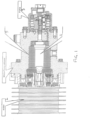
Figure 1 is a cross-sectional view of a typical hydraulic actuator design, which would generally require a 'wet' or immersed motor as there is no reliable sealing of the motor from the hydraulic fluid. -
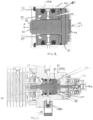
Figure 2 shows a view of an interface between a motor and a pump according to this disclosure, which enables a dry motor to be used. -
Figure 3 is a cross-sectional view of a hydraulic actuator design incorporating the interface design according to this disclosure. - As mentioned above, the solution described herein is applicable to many electric motor/fluidic load interfaces. The use of the solution provide herein will be described in relation to EHAs by way of example only.
-
Figure 1 shows a typical EHA design having a motor 1, which can be of any suitable design, connected via a rotating shaft 2 to drive ahydraulic pump 3. In the example shown, the motor is connected to the pump via a motor-pump adaptor 4 that houses the shaft 2. In other designs, the shaft may be formed as an integral part of one or other of the motor and the pump such that no adaptor is needed at the motor-pump interface. In the example, and in typical EHAs, the pump hydraulic fluid 5, e.g. oil or other pressurised fluid, may flow around the shaft 2 and across the interface (here adaptor 4) to the motor 1. As mentioned above, for this reason, the motor needs to be designed with protective features to allow it to be immersed in the fluid, which results in a relatively large, heavy motor design compared to a typical 'dry' motor. - The present disclosure provides an interface with an improved sealing arrangement between the pump and the motor which, in use, prevents hydraulic fluid leaking from the pump to the motor. The sealing arrangement includes a first, major, sealing part which will prevent most of the fluid from the pump passing, and then a second, minor sealing part that prevents any fluid that has passed the first sealing part from reaching the motor. This will be described in more detail with reference to the examples in
Figs. 2 and 3 . - The sealing arrangement includes a
shaft 20 which, in use, will provide the linkingshaft 20 between the motor 10 and thepump 30. Theshaft 20 comprises ashaft body 21 extending in an axial direction A from afirst end 22 which, in use, is in driving engagement with thepump 30, and asecond end 23 which, in use, is in engagement with the motor 10, such that rotation of the motor causes rotation of theshaft 20. Theshaft 20 extends through aninterface housing 40. This may be a separate adaptor part or may be part of the pump and/or the motor, - A
shoulder 25 is provided at the first end of the shaft and extends radially outwardly from theshaft body 21. The shoulder extends substantially across thehousing 40 in the radial dimension. - The sealing arrangement further comprises a first, major, seal 60 axially inwards of and in contact with the shoulder. The
first seal 60 may be integrally formed with or mounted to the shoulder or may be secured adjacent the shoulder. In the example shown, thefirst seal 60 is mounted in a groove formed in the seal holder block. The first seal may be a large surface area, flat seal but other seal designs, e.g. a circular seal, a seal with grooves, or other features, may also be used. - At the second end of the shaft, a second,
minor seal 70 is provided around the shaft. This may be a smaller seal and, in the example shown, is a lip seal that is secured in place by awasher 80. Aseal holder block 55 is provided between the first and the second seal. - The example also shows a
stop ring 90 that secures thewasher 80 against movement due to fluid pressure, andadditional seals 100 e.g. O-ring seals, but these are optional features. - In the region between the
first seal 60 and the second seal 70 (as defined in the axial direction A) grooves orchannels 110 are provided, extending in the radial direction, to capture any fluid that passes the first seal but is stopped by the second seal (typical microleakages) and lead such fluid away from the interface e.g. into a tank 120. The tank 120 may be removable, for emptying, or may be provided with a tap or drain to drain off fluid collected in the tank. Acheck valve 130 may be provided at the tank 120 to prevent leaked fluid flowing back from the tank into the motor area. - In operation, the pressure of the hydraulic fluid 300 in the
pump 30 acts on theshaft shoulder 25 which compresses thefirst seal 60 to seal across theinterface 40 in the axial direction and prevent, or substantially reduce fluid flow past the first seal towards the motor 10. Due to the large surface contact areas of the shoulder and the first seal (and the contact area that the shoulder presents to the fluid), the first seal is pressed more tightly against theseal holder 55 thus increasing the sealing effect. When designing the shoulder and the seal, consideration may be given to the roughness and the hardness of the contact surfaces to ensure optimal sealing and minimise wear on the seal. The seal dimensions should also be considered to minimise the frictions that tend to reduce the torque provided by the motor. - Despite the improved sealing of the first seal, there is the possibility that some fluid will leak past the first seal (so-called `microleakages') into the region of the
seal holder block 55. These leakages are contained by thesecond seal 70, secured by thewasher 80, before they can reach the motor. The leakages contained between the first and second seal can then be removed from the interface via grooves orchannels 110 which may be formed in the seal holder block by e.g. drilling, and the leakages may be fed out to a tank 120 or drained off from the sealing arrangement at the interface. - As mentioned above, in some examples, the shaft may be formed integrally with the motor or with the pump. The sealing arrangement of this disclosure can still isolate the motor from the fluid with the sealing arrangement as described, mounted around the shaft regardless of whether it is part of the motor, part of the pump or runs through an adaptor.
- Because of the improved sealing between the pump an the motor, the motor does not need to be a 'wet' or 'immersed' motor and does not need to be dimensioned to allow for drag losses and protective sleeves' Eddy current losses leading to larger coils. The overall actuator design can, therefore, be lighter and smaller.
Claims (15)
- A sealing arrangement for the interface between a fluidic load (30) and a motor (10), the sealing arrangement comprising:a rotating shaft (20) having a shaft body (21) extending along an axis (A) and having a first end (22), configured to, in use, be in driving engagement with a fluidic load, and a second end (23) configured to, in use, be in engagement with a motor (10) for rotation by the motor,the rotating shaft and a shoulder (25) extending radially outwards from the shaft body at the first end; wherein the sealing arrangement further comprises:a first, major seal (60) extending radially around the shaft;a second, minor seal (70) axially spaced from the first seal towards the second end and mounted around the shaft, anda seal holder block (55) located between the first seal and the second seal around the shaft body;the seals arranged such that pressure acting on an axially outer surface of the shoulder (25) causes the first seal (60) to create a seal with the seal holder block (55) against fluid flow past the shoulder (25), and wherein the second seal prevents flow of any fluid that has passed the first seal passing the second seal.
- The sealing arrangement of claim 1, wherein the first seal is a flat seal.
- The sealing arrangement of claim 1 or 2, wherein the sealing arrangement is mounted within a housing (40).
- The sealing arrangement of claim 3, wherein the first seal extends radially from the shaft substantially to the housing.
- The sealing arrangement of claim 3 or 4, wherein the radial dimension of the shoulder (25) is substantially the same as an inner radial dimension of the housing.
- The sealing arrangement of any preceding claim, wherein the first seal (60) is secured to, or fitted in a groove of the seal holder block (55).
- The sealing arrangement of any preceding claim, wherein the second seal is a lip seal.
- The sealing arrangement of any preceding claim, wherein the second seal is axially secured by a washer (80)
- The sealing arrangement of claim 8, wherein the washer is axially secured by a stop ring (90).
- The sealing arrangement of any preceding claim, further comprising one or more fluid drain channels (110) extending through the seal holder block for the passage of fluid in the area between the first and the second seal.
- The sealing arrangement of claim 10, further comprising a fluid collection tank (120) in fluid communication with the one or more fluid drain channels.
- The sealing arrangement of claim 11, further comprising a check valve associated with the tank to prevent return of fluid from the tank.
- An actuator assembly comprising:a motor (10);a fluidic load (30);a sealing arrangement as claimed in any preceding claim arranged between the motor and the load, the shaft (20) connected at the first end in driving engagement with the load, and at the second end in connection with, androtatable by the motor (10).
- The assembly of claim 13,wherein the fluidic load is a hydraulic pump.
- The assembly of claim 13, being an EHA or an EBHA.
Priority Applications (3)
| Application Number | Priority Date | Filing Date | Title |
|---|---|---|---|
| EP23306976.4A EP4556722A1 (en) | 2023-11-15 | 2023-11-15 | Motor load interface sealing arrangement |
| CA3254852A CA3254852A1 (en) | 2023-11-15 | 2024-09-25 | Motor load interface sealing arrangement |
| US18/937,921 US12607173B2 (en) | 2023-11-15 | 2024-11-05 | Motor load interface sealing arrangement |
Applications Claiming Priority (1)
| Application Number | Priority Date | Filing Date | Title |
|---|---|---|---|
| EP23306976.4A EP4556722A1 (en) | 2023-11-15 | 2023-11-15 | Motor load interface sealing arrangement |
Publications (1)
| Publication Number | Publication Date |
|---|---|
| EP4556722A1 true EP4556722A1 (en) | 2025-05-21 |
Family
ID=89119184
Family Applications (1)
| Application Number | Title | Priority Date | Filing Date |
|---|---|---|---|
| EP23306976.4A Pending EP4556722A1 (en) | 2023-11-15 | 2023-11-15 | Motor load interface sealing arrangement |
Country Status (3)
| Country | Link |
|---|---|
| US (1) | US12607173B2 (en) |
| EP (1) | EP4556722A1 (en) |
| CA (1) | CA3254852A1 (en) |
Citations (7)
| Publication number | Priority date | Publication date | Assignee | Title |
|---|---|---|---|---|
| EP1050680A2 (en) * | 1999-05-07 | 2000-11-08 | Brueninghaus Hydromatik Gmbh | Shaft seal for hydraulic machine |
| US20120308424A1 (en) * | 2010-01-26 | 2012-12-06 | Advics Co., Ltd. | Sealing device, and pump device using same |
| DE102014212183A1 (en) * | 2014-06-25 | 2015-12-31 | Robert Bosch Gmbh | Swash plate machine |
| US9273703B2 (en) * | 2010-09-16 | 2016-03-01 | Parker-Hannifin Corporation | Universal orientation electro-hydraulic actuator |
| US9663084B2 (en) * | 2013-10-09 | 2017-05-30 | Advics Co., Ltd. | Rotating pumping apparatus with seal mechanism |
| JP6339400B2 (en) * | 2014-03-31 | 2018-06-06 | Kyb株式会社 | Electric motor and hydraulic equipment |
| US20180156214A1 (en) * | 2015-09-14 | 2018-06-07 | Kyb Corporation | Pump unit and actuator |
Family Cites Families (8)
| Publication number | Priority date | Publication date | Assignee | Title |
|---|---|---|---|---|
| US3951417A (en) * | 1973-10-03 | 1976-04-20 | Vitaly Petrovich Chernykh | Rotary shaft end seal for apparatus operating under pressure |
| US4621981A (en) * | 1982-11-01 | 1986-11-11 | Borg-Warner Corporation | Pump improvement |
| JP5206457B2 (en) * | 2009-02-03 | 2013-06-12 | コベルコ建機株式会社 | Shaft lubrication device for hybrid work machines |
| US8997626B2 (en) | 2010-04-07 | 2015-04-07 | Parker-Hannifin Corporation | Electro-hydraulic actuator including a release valve assembly |
| US9500206B2 (en) | 2013-11-18 | 2016-11-22 | Warner Electric Technology Llc | Fluid pump for a linear actuator |
| EP3032712B1 (en) | 2014-12-12 | 2018-02-07 | Goodrich Control Systems | Motor for an electrohydraulic actuator |
| GB201516861D0 (en) | 2015-09-23 | 2015-11-04 | Parker Hannifin Mfg Uk Ltd | A motor pump assembly |
| CN110500257A (en) * | 2019-09-17 | 2019-11-26 | 兰州理工大学 | An air-gap non-oil-immersed axial piston motor pump |
-
2023
- 2023-11-15 EP EP23306976.4A patent/EP4556722A1/en active Pending
-
2024
- 2024-09-25 CA CA3254852A patent/CA3254852A1/en active Pending
- 2024-11-05 US US18/937,921 patent/US12607173B2/en active Active
Patent Citations (7)
| Publication number | Priority date | Publication date | Assignee | Title |
|---|---|---|---|---|
| EP1050680A2 (en) * | 1999-05-07 | 2000-11-08 | Brueninghaus Hydromatik Gmbh | Shaft seal for hydraulic machine |
| US20120308424A1 (en) * | 2010-01-26 | 2012-12-06 | Advics Co., Ltd. | Sealing device, and pump device using same |
| US9273703B2 (en) * | 2010-09-16 | 2016-03-01 | Parker-Hannifin Corporation | Universal orientation electro-hydraulic actuator |
| US9663084B2 (en) * | 2013-10-09 | 2017-05-30 | Advics Co., Ltd. | Rotating pumping apparatus with seal mechanism |
| JP6339400B2 (en) * | 2014-03-31 | 2018-06-06 | Kyb株式会社 | Electric motor and hydraulic equipment |
| DE102014212183A1 (en) * | 2014-06-25 | 2015-12-31 | Robert Bosch Gmbh | Swash plate machine |
| US20180156214A1 (en) * | 2015-09-14 | 2018-06-07 | Kyb Corporation | Pump unit and actuator |
Also Published As
| Publication number | Publication date |
|---|---|
| CA3254852A1 (en) | 2025-10-30 |
| US20250154967A1 (en) | 2025-05-15 |
| US12607173B2 (en) | 2026-04-21 |
Similar Documents
| Publication | Publication Date | Title |
|---|---|---|
| CA1304986C (en) | Centrifugal pump bearing arrangement | |
| US10323644B1 (en) | High-speed modular electric submersible pump assemblies | |
| EP2607696B1 (en) | Integrated electro-hydraulic device | |
| CA2683740C (en) | Fluid pump system | |
| EP1222393B1 (en) | Submersible motor with shaft seals | |
| EP0740078A1 (en) | A submersible canned motor transfer pump | |
| US10385856B1 (en) | Modular electric submersible pump assemblies with cooling systems | |
| US20190113038A1 (en) | Magnetic drive pump | |
| EP1200736B1 (en) | Shaftless canned rotor inline pipe pump | |
| CN102823117A (en) | Cooling system for a multistage electric motor | |
| US11506216B2 (en) | Water pump | |
| CA2935296C (en) | Integrated pressurized pump shaft seal assembly and method of use thereof | |
| CN105162289B (en) | Downhole electric drilling tool motor | |
| CN114313189B (en) | Sealing rim propeller | |
| US12607173B2 (en) | Motor load interface sealing arrangement | |
| US4768888A (en) | Unitary bearing member and motor incorporating the same | |
| KR102942605B1 (en) | Assembly for a hydraulic gear pump with force balance and internal cooling features | |
| US20220003089A1 (en) | Isolating a downhole-type electric machine | |
| US4342537A (en) | Impeller pump and seal | |
| EP3234417B1 (en) | Bearing isolator seal with enhanced rotor drive coupling | |
| JP7458284B2 (en) | Pump motors and pump devices | |
| WO2017154023A1 (en) | Motor with positive displacement helical pump inside motor shaft | |
| CN221990588U (en) | An integrated centrifugal pump driven by an axial magnetic field | |
| CN116181681A (en) | A low-resistance transmission component for a marine follow-up water pump | |
| CN115875302A (en) | Low flow resistance follow-up water pump for marine cooling water system |
Legal Events
| Date | Code | Title | Description |
|---|---|---|---|
| PUAI | Public reference made under article 153(3) epc to a published international application that has entered the european phase |
Free format text: ORIGINAL CODE: 0009012 |
|
| STAA | Information on the status of an ep patent application or granted ep patent |
Free format text: STATUS: THE APPLICATION HAS BEEN PUBLISHED |
|
| AK | Designated contracting states |
Kind code of ref document: A1 Designated state(s): AL AT BE BG CH CY CZ DE DK EE ES FI FR GB GR HR HU IE IS IT LI LT LU LV MC ME MK MT NL NO PL PT RO RS SE SI SK SM TR |
|
| STAA | Information on the status of an ep patent application or granted ep patent |
Free format text: STATUS: REQUEST FOR EXAMINATION WAS MADE |
|
| 17P | Request for examination filed |
Effective date: 20251113 |