EP4556720A1 - Blower device and air conditioning unit - Google Patents
Blower device and air conditioning unit Download PDFInfo
- Publication number
- EP4556720A1 EP4556720A1 EP24812354.9A EP24812354A EP4556720A1 EP 4556720 A1 EP4556720 A1 EP 4556720A1 EP 24812354 A EP24812354 A EP 24812354A EP 4556720 A1 EP4556720 A1 EP 4556720A1
- Authority
- EP
- European Patent Office
- Prior art keywords
- end portion
- axis
- width dimension
- impeller
- edge
- Prior art date
- Legal status (The legal status is an assumption and is not a legal conclusion. Google has not performed a legal analysis and makes no representation as to the accuracy of the status listed.)
- Pending
Links
Images






Classifications
-
- F—MECHANICAL ENGINEERING; LIGHTING; HEATING; WEAPONS; BLASTING
- F04—POSITIVE - DISPLACEMENT MACHINES FOR LIQUIDS; PUMPS FOR LIQUIDS OR ELASTIC FLUIDS
- F04D—NON-POSITIVE-DISPLACEMENT PUMPS
- F04D17/00—Radial-flow pumps, e.g. centrifugal pumps; Helico-centrifugal pumps
- F04D17/02—Radial-flow pumps, e.g. centrifugal pumps; Helico-centrifugal pumps having non-centrifugal stages, e.g. centripetal
- F04D17/04—Radial-flow pumps, e.g. centrifugal pumps; Helico-centrifugal pumps having non-centrifugal stages, e.g. centripetal of transverse-flow type
-
- F—MECHANICAL ENGINEERING; LIGHTING; HEATING; WEAPONS; BLASTING
- F04—POSITIVE - DISPLACEMENT MACHINES FOR LIQUIDS; PUMPS FOR LIQUIDS OR ELASTIC FLUIDS
- F04D—NON-POSITIVE-DISPLACEMENT PUMPS
- F04D29/00—Details, component parts, or accessories
- F04D29/40—Casings; Connections of working fluid
- F04D29/42—Casings; Connections of working fluid for radial or helico-centrifugal pumps
- F04D29/4206—Casings; Connections of working fluid for radial or helico-centrifugal pumps especially adapted for elastic fluid pumps
- F04D29/422—Discharge tongues
-
- F—MECHANICAL ENGINEERING; LIGHTING; HEATING; WEAPONS; BLASTING
- F24—HEATING; RANGES; VENTILATING
- F24F—AIR-CONDITIONING; AIR-HUMIDIFICATION; VENTILATION; USE OF AIR CURRENTS FOR SCREENING
- F24F1/00—Room units for air-conditioning, e.g. separate or self-contained units or units receiving primary air from a central station
- F24F1/0007—Indoor units, e.g. fan coil units
- F24F1/0018—Indoor units, e.g. fan coil units characterised by fans
- F24F1/0025—Cross-flow or tangential fans
-
- F—MECHANICAL ENGINEERING; LIGHTING; HEATING; WEAPONS; BLASTING
- F24—HEATING; RANGES; VENTILATING
- F24F—AIR-CONDITIONING; AIR-HUMIDIFICATION; VENTILATION; USE OF AIR CURRENTS FOR SCREENING
- F24F13/00—Details common to, or for air-conditioning, air-humidification, ventilation or use of air currents for screening
- F24F13/24—Means for preventing or suppressing noise
-
- F—MECHANICAL ENGINEERING; LIGHTING; HEATING; WEAPONS; BLASTING
- F24—HEATING; RANGES; VENTILATING
- F24F—AIR-CONDITIONING; AIR-HUMIDIFICATION; VENTILATION; USE OF AIR CURRENTS FOR SCREENING
- F24F1/00—Room units for air-conditioning, e.g. separate or self-contained units or units receiving primary air from a central station
- F24F1/0007—Indoor units, e.g. fan coil units
- F24F1/0011—Indoor units, e.g. fan coil units characterised by air outlets
-
- F—MECHANICAL ENGINEERING; LIGHTING; HEATING; WEAPONS; BLASTING
- F24—HEATING; RANGES; VENTILATING
- F24F—AIR-CONDITIONING; AIR-HUMIDIFICATION; VENTILATION; USE OF AIR CURRENTS FOR SCREENING
- F24F1/00—Room units for air-conditioning, e.g. separate or self-contained units or units receiving primary air from a central station
- F24F1/0007—Indoor units, e.g. fan coil units
- F24F1/0043—Indoor units, e.g. fan coil units characterised by mounting arrangements
- F24F1/0057—Indoor units, e.g. fan coil units characterised by mounting arrangements mounted in or on a wall
Definitions
- the present disclosure relates to a blowing device and an air conditioning unit.
- an indoor unit of an air conditioner (hereinafter referred to as an air conditioning unit), which is installed on a side wall of a room, instead of a ceiling, sucks air from a front surface or an upper surface, and blows out the air having undergone air conditioning from a blow-out port at a lower portion, has been widely used.
- an air conditioning unit which is installed on a side wall of a room, instead of a ceiling, sucks air from a front surface or an upper surface, and blows out the air having undergone air conditioning from a blow-out port at a lower portion.
- PTL 1 Japanese Unexamined Patent Application Publication No. 2016-50720
- a heat exchanger allowing heat to be exchanged between a refrigerant and air, and a blowing device are accommodated inside an air conditioning unit.
- the blowing device according to PTL 1 includes a cross-flow fan.
- the cross-flow fan involves an issue of an unstable phenomenon (so-called surging) in a blow-out flow, which occurs when air flow resistance increases due to clogging in a filter and frosting in a heat exchanger during cooling operation, for example.
- surging an unstable phenomenon
- a blowing device includes an impeller and a casing.
- the casing includes a tongue portion.
- the tongue portion extends in directions of an axis of the impeller and partitions a suction side and a blow-out side from each other.
- the tongue portion has a first end portion and a second end portion, and a central portion.
- the first end portion and the second end portion are positioned at both ends in the directions of the axis.
- the central portion is positioned between the first end portion and the second end portion.
- a width dimension of the tongue portion which represents a length from an edge on the suction side to an edge on the blow-out side of the tongue portion
- the width dimension on the first end portion of the tongue portion is smaller than the width dimension on the central portion of the tongue portion.
- width dimension on the first end portion of the tongue portion is smaller than the width dimension on the central portion of the tongue portion, it is possible to suppress surging.
- a blowing device is the blowing device according to the first aspect, in which the edge on the blow-out side of the central portion and the edge on the blow-out side of the first end portion are positioned at an identical position, when viewed in one of the directions of the axis.
- a blowing device is the blowing device according to the first aspect or the second aspect, in which the first end portion represents an end portion on which a wind speed decreases when the width dimension of the tongue portion is constant on the central portion, the first end portion, and the second end portion.
- a blowing device is the blowing device according to any one of the first aspect to the third aspect, in which each of the width dimension on the first end portion and the width dimension on the second end portion is smaller than the width dimension on the central portion.
- a blowing device is the blowing device according to any one of the first aspect to the fourth aspect, in which the width dimension on the first end portion is smaller than the width dimension on the second end portion.
- a blowing device is the blowing device according to any one of the first aspect to the fifth aspect, in which, on the first end portion, the width dimension of the tongue portion decreases in a stepwise manner as a distance from a portion closer to the central portion increases.
- a blowing device is the blowing device according to any one of the first aspect to the sixth aspect, in which a dimension of a gap between the central portion and the impeller is equal to a dimension of a gap between the first end portion and the impeller.
- a blowing device is the blowing device according to any one of the first aspect to the seventh aspect, in which, when a length dimension in the directions of the axis on the first end portion is defined as M, and an outer diameter of the impeller is defined as D, Formula (1) is satisfied. 0.10 ⁇ M / D ⁇ 1.35
- a blowing device is the blowing device according to any one of the first aspect to the eighth aspect, in which, when an angle, when viewed in one of the directions of the axis, formed by a first straight line extending from the axis to the edge on the suction side ofthe central portion and a second straight line extending from the axis to the edge on the blow-out side of the central portion is defined as ⁇ a, and an angle, when viewed in the one of the directions of the axis, formed by a third straight line extending from the axis to the edge on the suction side of the first end portion and a fourth straight line extending from the axis to the edge on the blow-out side of the first end portion is defined as ⁇ b, Formula (2) is satisfied. 0.39 ⁇ ⁇ b / ⁇ a ⁇ 0.98
- a blowing device is the blowing device according to any one of the first aspect to the ninth aspect, in which, when a length dimension in the directions of the axis on the first end portion is defined as M, an outer diameter of the impeller is defined as D, an angle, when viewed in one of the directions of the axis, formed by a first straight line extending from the axis to the edge on the suction side of the central portion and a second straight line extending from the axis to the edge on the blow-out side of the central portion is defined as ⁇ a, and an angle, when viewed in the one of the directions of the axis, formed by a third straight line extending from the axis to the edge on the suction side of the first end portion and a fourth straight line extending from the axis to the edge on the blow-out side of the first end portion is defined as ⁇ b, Formula (1) and Formula (2) are satisfied. 0.10 ⁇ M / D ⁇ 1.35 0.39 ⁇ ⁇ b / ⁇
- An air conditioning unit includes the blowing device according to any one of the first aspect to the tenth aspect.
- An air conditioning unit includes the blowing device according to any one of the first aspect to the tenth aspect.
- a diameter of a fan of the impeller is equal to or greater than 126 mm.
- An air conditioning unit includes the blowing device according to any one of the first aspect to the tenth aspect.
- the air conditioning unit satisfies Formula (3). (a diameter of a fan of the impeller / a height dimension of the air conditioning unit) ⁇ (126 / 300)
- an axis refers to an axis of an impeller 30.
- Directions of the axis refer to directions in which the axis of the impeller 30 extends.
- expressions indicating directions such as “upper”, “lower”, and “front” are used as appropriate, these expressions indicate respective directions in a state where an air conditioning unit 100 is attached and is used normally.
- upper-and-lower directions refer to vertical directions.
- cases in which the expression is used include not only a case where one is in "parallel” completely identically, but also a case where one is in "parallel” substantially identically.
- the air conditioning unit 100 is a wall-mounted type indoor unit attached to a wall surface in a room. Furthermore, the air conditioning unit 100 is coupled to an air conditioning outdoor unit 91 disposed outside the room via a refrigerant pipe 93 to constitute an air conditioner 90. The air conditioning unit 100 performs cooling operation and heating operation in the room in response to an operation performed via a remote controller, for example.
- the air conditioning unit 100 includes a blowing device 101, a heat exchanger 20, and a filter 40.
- the blowing device 101 includes a cross-flow fan including the impeller 30, and a casing 10.
- the cross-flow fan includes the impeller 30 having a cylindrical shape extending long in horizontal directions, and a motor for rotating the impeller 30.
- the impeller 30 has a plurality of fan blades 31 arranged along its circumference. The impeller 30 rotates to generate a flow of air flowing from a side where the heat exchanger 20 is present to a side where a blow-out port 10b is present.
- a diameter of the fan of the impeller 30 is not limited, the diameter is, for example, 126 mm or greater.
- the diameter of the fan of the impeller 30 corresponds to a diameter of a virtual circle coupling outer ends of the plurality of fan blades 31, when viewed in one of the directions of the axis (see a circle 30a indicated by a dotted line in Fig. 2 .
- the circle will be hereinafter referred to as a virtual circumscribed circle).
- the diameter of the fan of the impeller 30 is preferably equal to or greater than 130 mm, and more preferably equal to or greater than 135 mm.
- the diameter of the fan of the impeller 30 and a height dimension of the air conditioning unit 100 satisfy Formula (3). (the diameter of the fan of the impeller 30 / the height dimension of the air conditioning unit) ⁇ (126 / 300)
- a number of rotations of the motor of the impeller 30 is changed by a non-illustrated control device.
- the control device incorporated in the air conditioning unit 100 changes the number of rotations of the motor based on an operation input provided by a user via the remote controller, for example.
- the casing 10 is an assembly of members forming an outer contour and a frame of the air conditioning unit 100.
- the casing 10 supports and houses the filter 40, the heat exchanger 20, and the impeller 30.
- a suction port 10a for taking air inside the room is formed on an upper portion of the casing 10.
- the blow-out port 10b through which the air having undergone air conditioning is blown into the room is formed on a lower portion of the casing 10.
- the suction port 10a is positioned higher than an axis O serving as a rotation center of the impeller 30. More specifically, the suction port 10a is formed on a top surface (an upper surface) of the casing 10, through which air inside the room is sucked from a space above the air conditioning unit 100.
- the blow-out port 10b is positioned lower than the axis O. More specifically, the blow-out port 10b is formed on a front-side portion of a bottom surface of the casing 10, through which air is blown into a space in front of and below the air conditioning unit 100.
- the casing 10 includes a front panel 15, a rear guider 18, and a stabilizer 17.
- the stabilizer 17 and the rear guider 18 form a blow-out air flow path 10c through which air flowing from the impeller 30 to the blow-out port 10b is formed in a scroll shape.
- An upper portion of the rear guider 18 is positioned higher than the axis O.
- the front panel 15 is disposed on a front side of the filter 40.
- the stabilizer 17 is disposed closer to the front side than the rear guider 18.
- the stabilizer 17 includes a tongue portion 71 and support portions 73.
- the support portions 73 support the tongue portion 71.
- the tongue portion 71 extends in the directions of the axis of the impeller 30. That is, longitudinal directions of the tongue portion 71 are in parallel to the directions of the axis of the impeller 30. In an internal space of the blowing device 101, the tongue portion 71 partitions a suction side S1 and a blow-out side S2 from each other. The tongue portion 71 has a curved surface facing the impeller 30.
- the tongue portion 71 has a first end portion 71a and a second end portion 71b, and a central portion 71c.
- the first end portion 71a and the second end portion 71b are positioned at both ends in the directions of the axis.
- the first end portion 71a represents an end portion on which a wind speed decreases when a width dimension of the tongue portion 71 is constant on the central portion 71c, the first end portion 71a, and the second end portion 71b.
- the central portion 71c is positioned between the first end portion 71a and the second end portion 71b.
- a dimension of a gap between the tongue portion 71 and the impeller 30 does not change from the suction side S1 to the blow-out side S2 of the tongue portion 71.
- the dimension of the gap between the tongue portion 71 and the impeller 30 is not limited to this case, and may vary from the suction side S1 to the blow-out side S2.
- the dimension of the gap between the tongue portion 71 and the impeller 30 may increase from the blow-out side S2 to the suction side S1, or may decrease from the blow-out side S2 to the suction side S1.
- the width dimension on the first end portion 71a of the tongue portion 71 is smaller than the width dimension on the central portion 71c of the tongue portion 71.
- the width dimension of the tongue portion 71 refers to a length from an edge on the suction side S1 to an edge on the blow-out side S2 of the tongue portion 71.
- the width dimension on the first end portion 71a does not change in the directions of the axis.
- the edge on the blow-out side 71c of the central portion S2 and the edge on the blow-out side 71a of the first end portion S2 are positioned at an identical position. That is, a shape of the edge on the blow-out side S2 of the tongue portion 71 does not change in the directions of the axis.
- a dimension of a gap between the first end portion 71a and the impeller 30 is equal to a dimension of a gap between the central portion 71c and the impeller 30. More specifically, a shortest distance from the edge on the blow-out side S2 of the first end portion 71a to the virtual circumscribed circle of the impeller 30 is equal to a shortest distance from the edge on the blow-out side S2 of the central portion 71c to the virtual circumscribed circle of the impeller 30.
- M / D satisfies Formula (1). 0.10 ⁇ M / D ⁇ 1.35
- a range of M / D is preferably from 0.25 to 1.25, and more preferably from 0.40 to 1.15.
- an angle when viewed in one of the directions of the axis, formed by a first straight line L1 extending from the axis O to the edge on the suction side S1 of the central portion 71c and a second straight line L2 extending from the axis O to the edge on the blow-out side 71c of the central portion S2 is defined as ⁇ a.
- An angle, when viewed in the one of the directions of the axis, formed by a third straight line L3 extending from the axis O to the edge on the suction side S1 of the first end portion 71a and a fourth straight line L4 extending from the axis O to the edge on the blow-out side S2 of the first end portion 71a is defined as ⁇ b.
- the angle ⁇ a is greater than the angle ⁇ b.
- ⁇ b / ⁇ a satisfies Formula (2). 0.39 ⁇ ⁇ b / ⁇ a ⁇ 0.98
- a range of ⁇ b / ⁇ a is preferably from 0.42 to 0.95, and more preferably from 0.47 to 0.90.
- the width dimension on the second end portion 71b of the tongue portion 71 is smaller than the width dimension on the central portion 71c of the tongue portion 71.
- the width dimension on the second end portion 71b of the tongue portion 71 is identical to the width dimension on the first end portion 71a of the tongue portion 71.
- the width dimension on the second end portion 71b does not change in the directions of the axis.
- a length dimension M2 in the directions of the axis on the second end portion 71b is identical to a length dimension M in the directions of the axis on the first end portion 71a.
- the edge on the blow-out side S2 of the central portion 71c and the edge on the blow-out side S2 of the second end portion side 71b are positioned at an identical position. That is, a shape of the edge on the blow-out side S2 of the tongue portion 71 does not change in the longitudinal directions.
- a dimension of a gap between the second end portion 71b and the impeller 30 is equal to the dimension of the gap between the central portion 71c and the impeller 30. Specifically, a shortest distance from the edge on the blow-out side S2 of the second end portion 71b to the virtual circumscribed circle of the impeller 30 is equal to the shortest distance from the edge on the blow-out side S2 of the central portion 71c to the virtual circumscribed circle of the impeller 30.
- M' a length dimension in the directions of the axis on the second end portion 71b
- D the outer diameter of the impeller 30
- a range of M' / D is preferably from 0.25 to 1.25, and more preferably from 0.40 to 1.15.
- An angle, when viewed in one of the directions of the axis, formed by the first straight line L1 extending from the axis O to the edge on the suction side S1 of the central portion 71c and the second straight line L2 extending from the axis O to the edge on the blow-out side S2 of the central portion 71c is defined as ⁇ a.
- An angle, when viewed in the one of the directions of the axis, formed by a fifth straight line L5 extending from the axis O to the edge on the suction side S1 of the second end portion 71b and a sixth straight line L6 extending from the axis O to the edge on the blow-out side S2 of the second end portion 71b is defined as ⁇ b'.
- the angle ⁇ a is greater than the angle ⁇ b'. Specifically, ⁇ b' / ⁇ a satisfies Formula (2)'. 0.39 ⁇ ⁇ b ′ / ⁇ a ⁇ 0.98
- a range of ⁇ b' / ⁇ a is preferably from 0.42 to 0.95, and more preferably from 0.47 to 0.90.
- the heat exchanger 20 is a fin-and-tube type heat exchanger having a truncated wedge shape in a vertical cross-sectional view.
- the shape of the heat exchanger 20 is not limited.
- the heat exchanger 20 may have, for example, an inverted V shape.
- the heat exchanger 20 allows heat to be exchanged between air flowing from a side on which the suction port 10a is present to a side on which the impeller 30 is present and a refrigerant flowing through a tube.
- the heat exchanger 20 includes a plurality of aluminum heat transfer fins and a plurality of tubes passing through a plurality of holes formed in the heat transfer fins.
- An air flow upstream side of the impeller 30 is covered with the filter 40.
- the heat exchanger 20 positioned above and in front of the impeller 30 is covered with the filter 40.
- the filter 40 collects dust contained in air flowing from the suction port 10a to the heat exchanger 20.
- the width dimension on the first end portion 71a of the tongue portion 71 is smaller than the width dimension on the central portion 71c of the tongue portion 71.
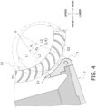
- a circulation vortex inside the cross-flow fan becomes smaller in size, similar to a circular arc illustrated by an solid line in Fig. 4 .
- the first end portion 71a represents an end portion on which a wind speed decreases when the width dimension of the tongue portion 71 is constant on the central portion 71c, the first end portion 71a, and the second end portion 71b.
- Each of the width dimension on the first end portion 71a and the width dimension on the second end portion 71b is smaller than the width dimension on the central portion 71c.
- each of the width dimension on the first end portion 71a and the width dimension on the second end portion 71b is smaller than the width dimension on the central portion 71c, it is possible to increase a blow-out speed, compared with a case where a width dimension on only one end is reduced.
- the dimension of the gap between the central portion 71c and the impeller 30 is equal to the dimension of the gap between the first end portion 71a and the impeller 30.
- the distance between the tongue portion 71 and the impeller 30 is kept constant over the whole length of the tongue portion 71. Therefore, there is no reduction in air blowing efficiency.
- the air conditioning unit 100 includes the blowing device 101 described above. As a result, the air conditioning unit 100 makes it possible to suppress occurrence of surging.
- the diameter of the fan of the impeller 30 is equal to or greater than 126 mm.
- the air conditioning unit 100 satisfies Formula (3). (the diameter of the fan of the impeller / the height dimension of the air conditioning unit) ⁇ (126 / 300)
- the width dimension on the first end portion 71a is identical to the width dimension on the second end portion 71b.
- each of the width dimension on the first end portion 71a and the width dimension on the second end portion 71b is not limited to the width dimension in the embodiment described above.
- the width dimension on the first end portion 71a and the width dimension on the second end portion 71b may be different from each other.
- the width dimension on the first end portion 71a may be smaller than the width dimension on the second end portion 71b.
- the length dimension M2 in the directions of the axis on the second end portion 71b is identical to the length dimension M in the directions of the axis on the first end portion 71a.
- the length dimension M2 in the directions of the axis on the second end portion 71b may be different from the length dimension M in the directions of the axis on the first end portion 71a.
- the length dimension M2 in the directions of the axis on the second end portion 71b may be smaller than the length dimension M in the directions of the axis on the first end portion 71a.
- each of both the width dimension on the first end portion 71a and the width dimension on the second end portion 71b is smaller than the width dimension on the central portion 71c.
- each of the width dimension on the first end portion 71a and the width dimension on the second end portion 71b is not limited to the width dimension in the embodiment described above.
- only the width dimension on the first end portion 71a may be smaller than the width dimension on the central portion 71c.
- the width dimension on the first end portion 71a is constant in the directions of the axis.
- the present disclosure is not limited to the embodiment described above.
- a width dimension of the tongue portion 71 may decrease in a stepwise manner as a distance from a portion closer to the central portion 71c increases.
- the third straight line L3 represents a straight line extending from the axis O to the edge on the suction side S1 at a center of the first end portion 71a.
- the width dimension of the tongue portion 71 may decrease in a slope shape, as a distance from a portion closer to the central portion 71c increases.
- the third straight line L3 represents a straight line extending from the axis O to the edge on the suction side S1 at the center of the first end portion 71a.
- the first end portion 71a and the second end portion 71b may have different shapes.
- Blowing devices in which diameters of fans of impellers are 115 mm, 126 mm, 135 mm, and 149 mm were prepared.
- an angle ⁇ a when viewed in one of the directions of the axis, formed by a first straight line extending from the axis to an edge on a suction side of a central portion and a second straight line extending from the axis to an edge on a blow-out side of the central portion
- a width dimension of a tongue portion was variously changed on both the first end portion and a second end portion, and an amount of increase in static pressure was measured.
- the width dimension of the tongue portion is set constant on the first end portion and the second end portion.
- Fig. 5 illustrates results.
- blowing devices in which values of ⁇ b / ⁇ a were 0.98, 0.85, 0.68, and 0.39 were prepared. Diameters of fans of impellers were each set to 135 mm. In each of the blowing devices, only a width dimension of a tongue portion was variously changed on both the first end portion and the second end portion, and an amount of increase in static pressure was measured. Fig. 6 illustrates results.
- a horizontal axis represents M / D
- a vertical axis represents an amount of increase in static pressure.
- Fig. 7 illustrates results.
- the horizontal axis represents ⁇ b / ⁇ a
- the vertical axis represents an amount of increase in static pressure.
- a width dimension of a tongue portion was changed on a second end portion, where a wind speed was originally high, and an amount of increase in static pressure was measured.
- a width dimension on the first end portion of the tongue portion was set to be identical to a width dimension on the central portion of the tongue portion.
- Fig. 9 illustrates results.
- the horizontal axis represents M / D
- the vertical axis represents an amount of increase in static pressure.
Landscapes
- Engineering & Computer Science (AREA)
- Mechanical Engineering (AREA)
- General Engineering & Computer Science (AREA)
- Chemical & Material Sciences (AREA)
- Combustion & Propulsion (AREA)
- Structures Of Non-Positive Displacement Pumps (AREA)
- Air-Conditioning Room Units, And Self-Contained Units In General (AREA)
Abstract
Description
- The present disclosure relates to a blowing device and an air conditioning unit.
- Conventionally, an indoor unit of an air conditioner (hereinafter referred to as an air conditioning unit), which is installed on a side wall of a room, instead of a ceiling, sucks air from a front surface or an upper surface, and blows out the air having undergone air conditioning from a blow-out port at a lower portion, has been widely used. As illustrated in PTL 1 (
Japanese Unexamined Patent Application Publication No. 2016-50720 PTL 1 includes a cross-flow fan. - The cross-flow fan involves an issue of an unstable phenomenon (so-called surging) in a blow-out flow, which occurs when air flow resistance increases due to clogging in a filter and frosting in a heat exchanger during cooling operation, for example.
- A blowing device according to a first aspect includes an impeller and a casing. The casing includes a tongue portion. The tongue portion extends in directions of an axis of the impeller and partitions a suction side and a blow-out side from each other. The tongue portion has a first end portion and a second end portion, and a central portion. The first end portion and the second end portion are positioned at both ends in the directions of the axis. The central portion is positioned between the first end portion and the second end portion. Regarding a width dimension of the tongue portion, which represents a length from an edge on the suction side to an edge on the blow-out side of the tongue portion, the width dimension on the first end portion of the tongue portion is smaller than the width dimension on the central portion of the tongue portion.
- Note herein that, since the width dimension on the first end portion of the tongue portion is smaller than the width dimension on the central portion of the tongue portion, it is possible to suppress surging.
- A blowing device according to a second aspect is the blowing device according to the first aspect, in which the edge on the blow-out side of the central portion and the edge on the blow-out side of the first end portion are positioned at an identical position, when viewed in one of the directions of the axis.
- A blowing device according to a third aspect is the blowing device according to the first aspect or the second aspect, in which the first end portion represents an end portion on which a wind speed decreases when the width dimension of the tongue portion is constant on the central portion, the first end portion, and the second end portion.
- A blowing device according to a fourth aspect is the blowing device according to any one of the first aspect to the third aspect, in which each of the width dimension on the first end portion and the width dimension on the second end portion is smaller than the width dimension on the central portion.
- A blowing device according to a fifth aspect is the blowing device according to any one of the first aspect to the fourth aspect, in which the width dimension on the first end portion is smaller than the width dimension on the second end portion.
- A blowing device according to a sixth aspect is the blowing device according to any one of the first aspect to the fifth aspect, in which, on the first end portion, the width dimension of the tongue portion decreases in a stepwise manner as a distance from a portion closer to the central portion increases.
- A blowing device according to a seventh aspect is the blowing device according to any one of the first aspect to the sixth aspect, in which a dimension of a gap between the central portion and the impeller is equal to a dimension of a gap between the first end portion and the impeller.
- A blowing device according to an eighth aspect is the blowing device according to any one of the first aspect to the seventh aspect, in which, when a length dimension in the directions of the axis on the first end portion is defined as M, and an outer diameter of the impeller is defined as D, Formula (1) is satisfied.

- A blowing device according to a ninth aspect is the blowing device according to any one of the first aspect to the eighth aspect, in which, when an angle, when viewed in one of the directions of the axis, formed by a first straight line extending from the axis to the edge on the suction side ofthe central portion and a second straight line extending from the axis to the edge on the blow-out side of the central portion is defined as θa, and an angle, when viewed in the one of the directions of the axis, formed by a third straight line extending from the axis to the edge on the suction side of the first end portion and a fourth straight line extending from the axis to the edge on the blow-out side of the first end portion is defined as θb, Formula (2) is satisfied.

- A blowing device according to a tenth aspect is the blowing device according to any one of the first aspect to the ninth aspect, in which, when a length dimension in the directions of the axis on the first end portion is defined as M, an outer diameter of the impeller is defined as D, an angle, when viewed in one of the directions of the axis, formed by a first straight line extending from the axis to the edge on the suction side of the central portion and a second straight line extending from the axis to the edge on the blow-out side of the central portion is defined as θa, and an angle, when viewed in the one of the directions of the axis, formed by a third straight line extending from the axis to the edge on the suction side of the first end portion and a fourth straight line extending from the axis to the edge on the blow-out side of the first end portion is defined as θb, Formula (1) and Formula (2) are satisfied.


- An air conditioning unit according to an eleventh aspect includes the blowing device according to any one of the first aspect to the tenth aspect.
- An air conditioning unit according to a twelfth aspect includes the blowing device according to any one of the first aspect to the tenth aspect. A diameter of a fan of the impeller is equal to or greater than 126 mm.
- An air conditioning unit according to a thirteenth aspect includes the blowing device according to any one of the first aspect to the tenth aspect. The air conditioning unit satisfies Formula (3).
(a diameter of a fan of the impeller / a height dimension of the air conditioning unit) ≥ (126 / 300) -
- [
Fig. 1] Fig. 1 is a configuration view of an air conditioning apparatus including an air conditioning outdoor unit and an air conditioning unit. - [
Fig. 2] Fig. 2 is a vertical cross-sectional view of the air conditioning unit taken at a central portion (a cross-sectional view taken along an arrow II-II inFig. 1 ). - [
Fig. 3] Fig. 3 is a perspective view of a tongue portion. - [
Fig. 4] Fig. 4 is a partially enlarged view of a cross section of the air conditioning unit. - [
Fig. 5] Fig. 5 is a graph illustrating a relationship between M / D and an amount of increase in static pressure, when a length dimension in directions of an axis is defined as M and an outer diameter of impeller is defined as D. - [
Fig. 6] Fig. 6 is another graph illustrating the relationship between M / D and the amount of increase in static pressure, when the length dimension in the directions of the axis is defined as M and the outer diameter of the impeller is defined as D. - [
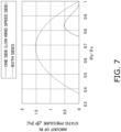
Fig. 7] Fig. 7 is a graph illustrating a relationship between an angular range of the tongue portion with respect to the axis and the amount of increase in static pressure. - [
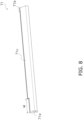
Fig. 8] Fig. 8 is a perspective view of a tongue portion according to a modification example. - [
Fig. 9] Fig. 9 is a graph illustrating a relationship between M / D and an amount of increase in static pressure, when a length dimension in the directions of the axis is defined as M and an outer diameter of the impeller is defined as D, according to the modification example. - [
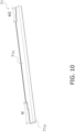
Fig. 10] Fig. 10 is a perspective view of a tongue portion according to another modification example. - [
Fig. 11] Fig. 11 is a perspective view of a tongue portion according to still another modification example. - In a following description, an axis refers to an axis of an
impeller 30. Directions of the axis refer to directions in which the axis of theimpeller 30 extends. Furthermore, although expressions indicating directions such as "upper", "lower", and "front" are used as appropriate, these expressions indicate respective directions in a state where anair conditioning unit 100 is attached and is used normally. For example, upper-and-lower directions refer to vertical directions. Furthermore, although an expression such as "parallel" is used in some cases similarly or identically, cases in which the expression is used include not only a case where one is in "parallel" completely identically, but also a case where one is in "parallel" substantially identically. - As illustrated in
Fig. 1 , theair conditioning unit 100 is a wall-mounted type indoor unit attached to a wall surface in a room. Furthermore, theair conditioning unit 100 is coupled to an air conditioningoutdoor unit 91 disposed outside the room via arefrigerant pipe 93 to constitute anair conditioner 90. Theair conditioning unit 100 performs cooling operation and heating operation in the room in response to an operation performed via a remote controller, for example. - As illustrated in
Fig. 2 , theair conditioning unit 100 includes a blowingdevice 101, aheat exchanger 20, and afilter 40. - The blowing
device 101 includes a cross-flow fan including theimpeller 30, and acasing 10. - The cross-flow fan includes the
impeller 30 having a cylindrical shape extending long in horizontal directions, and a motor for rotating theimpeller 30. Theimpeller 30 has a plurality offan blades 31 arranged along its circumference. Theimpeller 30 rotates to generate a flow of air flowing from a side where theheat exchanger 20 is present to a side where a blow-outport 10b is present. - As the
impeller 30 rotates, air flows from inside the room to theheat exchanger 20 via thefilter 40. The air that has passed through theheat exchanger 20 is blown into the room. - Although a diameter of the fan of the
impeller 30 is not limited, the diameter is, for example, 126 mm or greater. The diameter of the fan of theimpeller 30 corresponds to a diameter of a virtual circle coupling outer ends of the plurality offan blades 31, when viewed in one of the directions of the axis (see acircle 30a indicated by a dotted line inFig. 2 . The circle will be hereinafter referred to as a virtual circumscribed circle). The diameter of the fan of theimpeller 30 is preferably equal to or greater than 130 mm, and more preferably equal to or greater than 135 mm. - The diameter of the fan of the
impeller 30 and a height dimension of theair conditioning unit 100 satisfy Formula (3).(the diameter of the fan of the impeller 30 / the height dimension of the air conditioning unit) ≥ (126 / 300) - A number of rotations of the motor of the
impeller 30 is changed by a non-illustrated control device. The control device incorporated in theair conditioning unit 100 changes the number of rotations of the motor based on an operation input provided by a user via the remote controller, for example. - The
casing 10 is an assembly of members forming an outer contour and a frame of theair conditioning unit 100. Thecasing 10 supports and houses thefilter 40, theheat exchanger 20, and theimpeller 30. - On an upper portion of the
casing 10, asuction port 10a for taking air inside the room is formed. On a lower portion of thecasing 10, the blow-outport 10b through which the air having undergone air conditioning is blown into the room is formed. Thesuction port 10a is positioned higher than an axis O serving as a rotation center of theimpeller 30. More specifically, thesuction port 10a is formed on a top surface (an upper surface) of thecasing 10, through which air inside the room is sucked from a space above theair conditioning unit 100. The blow-outport 10b is positioned lower than the axis O. More specifically, the blow-outport 10b is formed on a front-side portion of a bottom surface of thecasing 10, through which air is blown into a space in front of and below theair conditioning unit 100. - The
casing 10 includes afront panel 15, arear guider 18, and astabilizer 17. Thestabilizer 17 and therear guider 18 form a blow-outair flow path 10c through which air flowing from theimpeller 30 to the blow-outport 10b is formed in a scroll shape. An upper portion of therear guider 18 is positioned higher than the axis O. Thefront panel 15 is disposed on a front side of thefilter 40. Thestabilizer 17 is disposed closer to the front side than therear guider 18. Thestabilizer 17 includes atongue portion 71 andsupport portions 73. Thesupport portions 73 support thetongue portion 71. - As the
impeller 30 rotates, air flows from inside the room to theheat exchanger 20 via thesuction port 10a and thefilter 40. The air that has passed through theheat exchanger 20 flows to the blow-outair flow path 10c and is blown into the room from the blow-outport 10b. - As illustrated in
Fig. 3 , thetongue portion 71 extends in the directions of the axis of theimpeller 30. That is, longitudinal directions of thetongue portion 71 are in parallel to the directions of the axis of theimpeller 30. In an internal space of theblowing device 101, thetongue portion 71 partitions a suction side S1 and a blow-out side S2 from each other. Thetongue portion 71 has a curved surface facing theimpeller 30. - The
tongue portion 71 has afirst end portion 71a and asecond end portion 71b, and acentral portion 71c. Thefirst end portion 71a and thesecond end portion 71b are positioned at both ends in the directions of the axis. Thefirst end portion 71a represents an end portion on which a wind speed decreases when a width dimension of thetongue portion 71 is constant on thecentral portion 71c, thefirst end portion 71a, and thesecond end portion 71b. Thecentral portion 71c is positioned between thefirst end portion 71a and thesecond end portion 71b. - A dimension of a gap between the
tongue portion 71 and theimpeller 30 does not change from the suction side S1 to the blow-out side S2 of thetongue portion 71. However, the dimension of the gap between thetongue portion 71 and theimpeller 30 is not limited to this case, and may vary from the suction side S1 to the blow-out side S2. Specifically, the dimension of the gap between thetongue portion 71 and theimpeller 30 may increase from the blow-out side S2 to the suction side S1, or may decrease from the blow-out side S2 to the suction side S1. - Regarding a width dimension of the
tongue portion 71, the width dimension on thefirst end portion 71a of thetongue portion 71 is smaller than the width dimension on thecentral portion 71c of thetongue portion 71. The width dimension of thetongue portion 71 refers to a length from an edge on the suction side S1 to an edge on the blow-out side S2 of thetongue portion 71. - The width dimension on the
first end portion 71a does not change in the directions of the axis. - On the edge on the suction side S1, there is a step between the
first end portion 71a and thecentral portion 71c. - When viewed in one of the directions of the axis, the edge on the blow-out
side 71c of the central portion S2 and the edge on the blow-outside 71a of the first end portion S2 are positioned at an identical position. That is, a shape of the edge on the blow-out side S2 of thetongue portion 71 does not change in the directions of the axis. - A dimension of a gap between the
first end portion 71a and theimpeller 30 is equal to a dimension of a gap between thecentral portion 71c and theimpeller 30. More specifically, a shortest distance from the edge on the blow-out side S2 of thefirst end portion 71a to the virtual circumscribed circle of theimpeller 30 is equal to a shortest distance from the edge on the blow-out side S2 of thecentral portion 71c to the virtual circumscribed circle of theimpeller 30. - When a length dimension in the directions of the axis on the
first end portion 71a is defined as M, and an outer diameter of theimpeller 30 is defined as D, M / D satisfies Formula (1).
- A range of M / D is preferably from 0.25 to 1.25, and more preferably from 0.40 to 1.15.
- As illustrated in
Fig. 4 , an angle, when viewed in one of the directions of the axis, formed by a first straight line L1 extending from the axis O to the edge on the suction side S1 of thecentral portion 71c and a second straight line L2 extending from the axis O to the edge on the blow-outside 71c of the central portion S2 is defined as θa. An angle, when viewed in the one of the directions of the axis, formed by a third straight line L3 extending from the axis O to the edge on the suction side S1 of thefirst end portion 71a and a fourth straight line L4 extending from the axis O to the edge on the blow-out side S2 of thefirst end portion 71a is defined as θb. The angle θa is greater than the angle θb. Specifically, θb / θa satisfies Formula (2).
- A range of θb / θa is preferably from 0.42 to 0.95, and more preferably from 0.47 to 0.90.
- The width dimension on the
second end portion 71b of thetongue portion 71 is smaller than the width dimension on thecentral portion 71c of thetongue portion 71. The width dimension on thesecond end portion 71b of thetongue portion 71 is identical to the width dimension on thefirst end portion 71a of thetongue portion 71. - The width dimension on the
second end portion 71b does not change in the directions of the axis. A length dimension M2 in the directions of the axis on thesecond end portion 71b is identical to a length dimension M in the directions of the axis on thefirst end portion 71a. - On the edge on the suction side S1, there is a step between the
second end portion 71b and thecentral portion 71c. - When viewed in one of the directions of the axis, the edge on the blow-out side S2 of the
central portion 71c and the edge on the blow-out side S2 of the secondend portion side 71b are positioned at an identical position. That is, a shape of the edge on the blow-out side S2 of thetongue portion 71 does not change in the longitudinal directions. - A dimension of a gap between the
second end portion 71b and theimpeller 30 is equal to the dimension of the gap between thecentral portion 71c and theimpeller 30. Specifically, a shortest distance from the edge on the blow-out side S2 of thesecond end portion 71b to the virtual circumscribed circle of theimpeller 30 is equal to the shortest distance from the edge on the blow-out side S2 of thecentral portion 71c to the virtual circumscribed circle of theimpeller 30. - When a length dimension in the directions of the axis on the
second end portion 71b is defined as M', and the outer diameter of theimpeller 30 is defined as D, M' / D satisfies Formula (1)'.
- A range of M' / D is preferably from 0.25 to 1.25, and more preferably from 0.40 to 1.15.
- An angle, when viewed in one of the directions of the axis, formed by the first straight line L1 extending from the axis O to the edge on the suction side S1 of the
central portion 71c and the second straight line L2 extending from the axis O to the edge on the blow-out side S2 of thecentral portion 71c is defined as θa. An angle, when viewed in the one of the directions of the axis, formed by a fifth straight line L5 extending from the axis O to the edge on the suction side S1 of thesecond end portion 71b and a sixth straight line L6 extending from the axis O to the edge on the blow-out side S2 of thesecond end portion 71b is defined as θb'. The angle θa is greater than the angle θb'. Specifically, θb' / θa satisfies Formula (2)'.
- A range of θb' / θa is preferably from 0.42 to 0.95, and more preferably from 0.47 to 0.90.
- The
heat exchanger 20 is a fin-and-tube type heat exchanger having a truncated wedge shape in a vertical cross-sectional view. The shape of theheat exchanger 20 is not limited. Theheat exchanger 20 may have, for example, an inverted V shape. Theheat exchanger 20 allows heat to be exchanged between air flowing from a side on which thesuction port 10a is present to a side on which theimpeller 30 is present and a refrigerant flowing through a tube. Theheat exchanger 20 includes a plurality of aluminum heat transfer fins and a plurality of tubes passing through a plurality of holes formed in the heat transfer fins. The tubes, which are copper heat transfer tubes, each have an outer diameter of 5 mm or 4 mm. - An air flow upstream side of the
impeller 30 is covered with thefilter 40. Specifically, theheat exchanger 20 positioned above and in front of theimpeller 30 is covered with thefilter 40. Thefilter 40 collects dust contained in air flowing from thesuction port 10a to theheat exchanger 20. - (4-1)
Both end portions in the directions of the axis of the cross-flow fan are more affected by lateral suction than a central portion. As a result, separation of a flow of air occurs on side surfaces. Therefore, air is rarely sucked at both the end portions of the cross-flow fan, allowing a circulation vortex of air inside the fan to increase in size. As a result, a wind speed decreases, allowing surging to occur. At this time, a circulation vortex at each of both the end portions inside the cross-flow fan becomes larger in size than a circulation vortex at the central portion, as illustrated by a broken-line arc inFig. 4 . - In the cross-flow fan, regarding a width dimension of the
tongue portion 71, which represents a length from the edge on the suction side S1 to the edge on the blow-out side S2 of thetongue portion 71, the width dimension on thefirst end portion 71a of thetongue portion 71 is smaller than the width dimension on thecentral portion 71c of thetongue portion 71. As a result, on each of thefirst end portion 71a and thesecond end portion 71b, a circulation vortex inside the cross-flow fan becomes smaller in size, similar to a circular arc illustrated by an solid line inFig. 4 . As a result, it is possible to increase static pressure in a blow-out air flow path, making it possible to increase a wind speed. As a result, it is possible to suppress occurrence of surging. - (4-2)
The edge on the blow-out side S2 of thecentral portion 71c and the edge on the blow-out side S2 of thefirst end portion 71a are positioned at an identical position, when viewed in one of the directions of the axis. - Note herein that, when viewed in one of the directions of the axis, a position of the edge on the blow-out side S2 does not change between the
central portion 71c and thefirst end portion 71a. Therefore, since a distance between thetongue portion 71 and theimpeller 30 is kept constant over a whole length of thetongue portion 71, preventing air blowing efficiency from being lowered. - (4-3)
Thefirst end portion 71a represents an end portion on which a wind speed decreases when the width dimension of thetongue portion 71 is constant on thecentral portion 71c, thefirst end portion 71a, and thesecond end portion 71b. - Therefore, it is possible to increase a blow-out speed on the end portion where a wind speed is originally low.
- (4-4)
Each of the width dimension on thefirst end portion 71a and the width dimension on thesecond end portion 71b is smaller than the width dimension on thecentral portion 71c. - Note herein that, since each of the width dimension on the
first end portion 71a and the width dimension on thesecond end portion 71b is smaller than the width dimension on thecentral portion 71c, it is possible to increase a blow-out speed, compared with a case where a width dimension on only one end is reduced. - (4-5)
The dimension of the gap between thecentral portion 71c and theimpeller 30 is equal to the dimension of the gap between thefirst end portion 71a and theimpeller 30. - Note herein that the distance between the
tongue portion 71 and theimpeller 30 is kept constant over the whole length of thetongue portion 71. Therefore, there is no reduction in air blowing efficiency. - (4-6)
When the length dimension in the directions of the axis on thefirst end portion 71a is defined as M, and the outer diameter of theimpeller 30 is defined as D, Formula (1) is satisfied.
- As illustrated in
Figs. 5 and6 , when M / D ranges from 0.10 to 1.35, occurrence of surging is suppressed. - (4-7)
When an angle, when viewed in one of the directions of the axis, formed by the first straight line L1 extending from the axis O to the edge on the suction side S1 of thecentral portion 71c and the second straight line L2 extending from the axis O to the edge on the blow-out side S2 of thecentral portion 71c is defined as θa, and an angle, when viewed in the one of the directions of the axis, formed by the third straight line L3 extending from the axis O to the edge on the suction side S1 of thefirst end portion 71a and the fourth straight line L4 extending from the axis O to the edge on the blow-out side S2 of thefirst end portion 71a is defined as θb, Formula (2) is satisfied.
- As illustrated in
Fig. 7 , when θb / θa ranges from 0.39 to 0.98, occurrence of surging is suppressed. - (4-8)
Theair conditioning unit 100 includes theblowing device 101 described above. As a result, theair conditioning unit 100 makes it possible to suppress occurrence of surging. - (4-9)
The diameter of the fan of theimpeller 30 is equal to or greater than 126 mm. - According to this configuration, since the cross-flow fan having a large diameter of the fan of the
impeller 30 is used, it is possible to reduce noise and power consumption during air conditioning operation. - (4-10)
Theair conditioning unit 100 satisfies Formula (3).(the diameter of the fan of the impeller / the height dimension of the air conditioning unit) ≥ (126 / 300) - According to this configuration, since the cross-flow fan having a large diameter of the fan of the
impeller 30 with respect to an indoor unit main body is used, it is possible to reduce noise and power consumption during air conditioning operation. - In the embodiment described above, the width dimension on the
first end portion 71a is identical to the width dimension on thesecond end portion 71b. However, each of the width dimension on thefirst end portion 71a and the width dimension on thesecond end portion 71b is not limited to the width dimension in the embodiment described above. The width dimension on thefirst end portion 71a and the width dimension on thesecond end portion 71b may be different from each other. For example, the width dimension on thefirst end portion 71a may be smaller than the width dimension on thesecond end portion 71b. - In this case, it is possible to make a wind speed higher on the
first end portion 71a, where a wind speed is originally low, than a wind speed on thesecond end portion 71b. - In the embodiment described above, the length dimension M2 in the directions of the axis on the
second end portion 71b is identical to the length dimension M in the directions of the axis on thefirst end portion 71a. However, the length dimension M2 in the directions of the axis on thesecond end portion 71b may be different from the length dimension M in the directions of the axis on thefirst end portion 71a. For example, the length dimension M2 in the directions of the axis on thesecond end portion 71b may be smaller than the length dimension M in the directions of the axis on thefirst end portion 71a. - In this case, it is possible to make a wind speed higher on the
first end portion 71a, where a wind speed is originally low, than a wind speed on thesecond end portion 71b. - In the embodiment described above and Modification Example A, each of both the width dimension on the
first end portion 71a and the width dimension on thesecond end portion 71b is smaller than the width dimension on thecentral portion 71c. However, each of the width dimension on thefirst end portion 71a and the width dimension on thesecond end portion 71b is not limited to the width dimension in the embodiment described above. For example, only the width dimension on thefirst end portion 71a may be smaller than the width dimension on thecentral portion 71c. - In this case, it is possible to make a wind speed higher on the
first end portion 71a, where a wind speed is originally low. - In the embodiment described above, the width dimension on the
first end portion 71a is constant in the directions of the axis. However, the present disclosure is not limited to the embodiment described above. As illustrated inFig. 10 , on thefirst end portion 71a, a width dimension of thetongue portion 71 may decrease in a stepwise manner as a distance from a portion closer to thecentral portion 71c increases. - In this case, continuity in the directions of the axis of a circulation vortex generated inside the
impeller 30 is rarely lost, easily achieving a stable air flow. - In the case of Modification Example D, regarding Formula (2), the third straight line L3 represents a straight line extending from the axis O to the edge on the suction side S1 at a center of the
first end portion 71a. - As illustrated in
Fig. 11 , on thefirst end portion 71a, the width dimension of thetongue portion 71 may decrease in a slope shape, as a distance from a portion closer to thecentral portion 71c increases. - In this case, since continuity in the directions of the axis of a circulation vortex generated inside the
impeller 30 is not lost, the air flow stabilizes. - In the case of Modification Example E, regarding Formula (2), the third straight line L3 represents a straight line extending from the axis O to the edge on the suction side S1 at the center of the
first end portion 71a. - As illustrated in
Fig. 11 , thefirst end portion 71a and thesecond end portion 71b may have different shapes. - Blowing devices in which diameters of fans of impellers are 115 mm, 126 mm, 135 mm, and 149 mm were prepared. In each of the blowing devices, for an angle θa, when viewed in one of the directions of the axis, formed by a first straight line extending from the axis to an edge on a suction side of a central portion and a second straight line extending from the axis to an edge on a blow-out side of the central portion, and an angle θb, as viewed in the one of the directions of the axis, formed by a third straight line extending from the axis to an edge on the suction side of a first end portion and a fourth straight line extending from the axis to an edge on the blow-out side of the first end portion were set to be θb / θa = 0.85. In each of the blowing devices, only a width dimension of a tongue portion was variously changed on both the first end portion and a second end portion, and an amount of increase in static pressure was measured. The width dimension of the tongue portion is set constant on the first end portion and the second end portion.
Fig. 5 illustrates results. - Furthermore, blowing devices in which values of θb / θa were 0.98, 0.85, 0.68, and 0.39 were prepared. Diameters of fans of impellers were each set to 135 mm. In each of the blowing devices, only a width dimension of a tongue portion was variously changed on both the first end portion and the second end portion, and an amount of increase in static pressure was measured.
Fig. 6 illustrates results. - In
Figs. 5 and6 , a horizontal axis represents M / D, and a vertical axis represents an amount of increase in static pressure. As results of tests, an amount of increase in static pressure increased when M / D ranged from 0.10 to 1.35. This means that occurrence of surging was suppressed. - A blowing device in which a diameter of a fan of an impeller was 135 mm was prepared. It was set that M / D = 0.30. Amounts of increase in static pressure were measured by variously changing θb / θa. Amounts of increase in static pressure were measured when θb / θa was changed on both the first end portion and the second end portion, and when θb / θa was changed only on the first end portion. When θb / θa was changed on both the first end portion and the second end portion, a value of θb / θa on the first end portion was set to be identical to a value of θb / θa on the second end portion.
Fig. 7 illustrates results. - In
Fig. 7 , the horizontal axis represents θb / θa, and the vertical axis represents an amount of increase in static pressure. As results of tests, when θb / θa was changed on both the first end portion and the second end portion, an amount of increase in static pressure increased when θb / θa ranged from 0.39 to 0.98. This means that occurrence of surging was suppressed. - Blowing devices in which diameters of fans of impellers were 115 mm, 126 mm, 135 mm, and 149 mm were prepared. In each of the blowing devices, it was set that θb / θa = 0.85. In each of the blowing devices, only a width dimension of a tongue portion was variously changed on a first end portion, and an amount of increase in static pressure was measured. A width dimension on a second end portion of the tongue portion was set to be identical to a width dimension on a central portion of the tongue portion.
- Furthermore, for one of the blowing devices, in which the diameter of the fan of the impeller was 135 mm, a width dimension of a tongue portion was changed on a second end portion, where a wind speed was originally high, and an amount of increase in static pressure was measured. In this example, a width dimension on the first end portion of the tongue portion was set to be identical to a width dimension on the central portion of the tongue portion.
-
Fig. 9 illustrates results. - In
Fig. 9 , the horizontal axis represents M / D, and the vertical axis represents an amount of increase in static pressure. As results of tests, an amount of increase in static pressure increased when M / D ranged from 0.10 to 1.35. This means that occurrence of surging was suppressed even when only the width dimension on the first end portion of the tongue portion was changed. - While the embodiment of the present disclosure has been described above, it will be understood that various modifications in form and detail may be made therein without departing from the spirit and scope of the present disclosure as set forth in the appended claims.
-
- 10
- Casing
- 10a
- Suction port
- 10b
- Blow-out port
- 10c
- Blow-out air flow path
- 17
- Stabilizer
- 18
- Rear guider
- 20
- Heat exchanger
- 30
- Impeller
- 30a
- Virtual circle (virtual circumscribed circle) coupling outer ends of fan blades
- 31
- Fan blade
- 71
- Tongue portion of stabilizer
- 71a
- First end portion
- 71b
- Second end portion
- 71c
- Central portion
- 73
- Support portion of stabilizer
- 100
- Air conditioning unit
- 101
- Blowing device
- O
- Axis of fan
- L1
- First straight line
- L2
- Second straight line
- L3
- Third straight line
- L4
- Fourth straight line
- S1
- Suction side
- S2
- Blow-out side
- PTL 1:
Japanese Unexamined Patent Application Publication No. 2016-50720
Claims (13)
- A blowing device (101) comprising:an impeller (30); anda casing (10) including a tongue portion (71) extending in directions of an axis of the impeller and partitioning a suction side (S1) and a blow-out side (S2) from each other,whereinthe tongue portion has a first end portion (71a) and a second end portion (71b) positioned at both ends in the directions of the axis, and a central portion (71c) positioned between the first end portion and the second end portion, and,regarding a width dimension of the tongue portion, the width dimension representing a length from an edge on the suction side to an edge on the blow-out side of the tongue portion, the width dimension on the first end portion of the tongue portion is smaller than the width dimension on the central portion of the tongue portion.
- The blowing device according to claim 1, wherein the edge on the blow-out side of the central portion and the edge on the blow-out side of the first end portion are positioned at an identical position, when viewed in one of the directions of the axis.
- The blowing device according to claim 1 or 2, wherein the first end portion represents an end portion on which a wind speed decreases when the width dimension of the tongue portion is constant on the central portion, the first end portion, and the second end portion.
- The blowing device according to any one of claims 1 to 3, wherein each of the width dimension on the first end portion and the width dimension on the second end portion is smaller than the width dimension on the central portion.
- The blowing device according to any one of claims 1 to 4, wherein the width dimension on the first end portion is smaller than the width dimension on the second end portion.
- The blowing device according to any one of claims 1 to 5, wherein, on the first end portion, the width dimension of the tongue portion decreases in a stepwise manner as a distance from a portion closer to the central portion increases.
- The blowing device according to any one of claims 1 to 6, wherein a dimension of a gap between the central portion and the impeller is equal to a dimension of a gap between the first end portion and the impeller.
- The blowing device according to any one of claims 1 to 7, wherein, when a length dimension in the directions of the axis on the first end portion is defined as M, and an outer diameter of the impeller is defined as D, Formula (1) is satisfied.

- The blowing device according to any one of claims 1 to 8, wherein, when an angle, when viewed in one of the directions of the axis, formed by a first straight line (L1) extending from an axis (O) to the edge on the suction side of the central portion and a second straight line (L2) extending from the axis to the edge on the blow-out side of the central portion is defined as θa, and an angle, when viewed in the one of the directions of the axis, formed by a third straight line (L3) extending from the axis to the edge on the suction side of the first end portion and a fourth straight line (L4) extending from the axis to the edge on the blow-out side of the first end portion is defined as θb, Formula (2) is satisfied.

- The blowing device according to any one of claims 1 to 9, wherein, when a length dimension in the directions of the axis on the first end portion is defined as M, an outer diameter of the impeller is defined as D, an angle, when viewed in one of the directions of the axis, formed by a first straight line extending from the axis to the edge on the suction side of the central portion and a second straight line extending from the axis to the edge on the blow-out side of the central portion is defined as θa, and an angle, when viewed in the one of the directions of the axis, an angle formed by a third straight line extending from the axis to the edge on the suction side of the first end portion and a fourth straight line extending from the axis to the edge on the blow-out side of the first end portion is defined as θb, Formula (1) and Formula (2) are satisfied.


- An air conditioning unit (100) comprising the blowing device according to any one of claims 1 to 10.
- An air conditioning unit comprising the blowing device according to any one of claims 1 to 10, wherein a diameter of a fan of the impeller is equal to or greater than 126 mm.
- An air conditioning unit comprising the blowing device according to any one of claims 1 to 10, wherein Formula (3) is satisfied.
(a diameter of a fan of the impeller / a height dimension of the air conditioning unit) ≥ (126 / 300)
Applications Claiming Priority (2)
| Application Number | Priority Date | Filing Date | Title |
|---|---|---|---|
| JP2023170753A JP7678358B2 (en) | 2023-09-29 | 2023-09-29 | Blower and air conditioning unit |
| PCT/JP2024/034557 WO2025070682A1 (en) | 2023-09-29 | 2024-09-27 | Blower device and air conditioning unit |
Publications (2)
| Publication Number | Publication Date |
|---|---|
| EP4556720A1 true EP4556720A1 (en) | 2025-05-21 |
| EP4556720A4 EP4556720A4 (en) | 2025-10-15 |
Family
ID=94129687
Family Applications (1)
| Application Number | Title | Priority Date | Filing Date |
|---|---|---|---|
| EP24812354.9A Pending EP4556720A4 (en) | 2023-09-29 | 2024-09-27 | BLOWER DEVICE AND AIR CONDITIONING UNIT |
Country Status (4)
| Country | Link |
|---|---|
| EP (1) | EP4556720A4 (en) |
| JP (1) | JP7678358B2 (en) |
| CN (1) | CN121909337A (en) |
| WO (1) | WO2025070682A1 (en) |
Family Cites Families (9)
| Publication number | Priority date | Publication date | Assignee | Title |
|---|---|---|---|---|
| JPS5838606B1 (en) * | 1980-10-25 | 1983-08-24 | Teruo Yamamoto | |
| JP3700578B2 (en) * | 2000-12-22 | 2005-09-28 | ダイキン工業株式会社 | Air conditioner indoor unit |
| KR101115788B1 (en) * | 2004-05-12 | 2012-03-09 | 엘지전자 주식회사 | Structures for stabilizer of air conditioner |
| JP4539855B2 (en) * | 2005-06-30 | 2010-09-08 | 株式会社富士通ゼネラル | Air conditioner |
| KR101392088B1 (en) * | 2007-10-22 | 2014-05-12 | 엘지전자 주식회사 | A ceiling-mounted type air conditioner |
| JP5716766B2 (en) * | 2013-02-12 | 2015-05-13 | ダイキン工業株式会社 | Air conditioner |
| JP6472625B2 (en) | 2014-09-01 | 2019-02-20 | 日立ジョンソンコントロールズ空調株式会社 | Air conditioner |
| CN209910140U (en) * | 2019-05-13 | 2020-01-07 | 宁波奥克斯电气股份有限公司 | Anti-surge volute tongue and air conditioner |
| KR102784232B1 (en) * | 2019-11-22 | 2025-03-21 | 삼성전자주식회사 | Air conditioner |
-
2023
- 2023-09-29 JP JP2023170753A patent/JP7678358B2/en active Active
-
2024
- 2024-09-27 CN CN202480061094.5A patent/CN121909337A/en active Pending
- 2024-09-27 EP EP24812354.9A patent/EP4556720A4/en active Pending
- 2024-09-27 WO PCT/JP2024/034557 patent/WO2025070682A1/en not_active Ceased
Also Published As
| Publication number | Publication date |
|---|---|
| JP2025060188A (en) | 2025-04-10 |
| JP7678358B2 (en) | 2025-05-16 |
| EP4556720A4 (en) | 2025-10-15 |
| WO2025070682A1 (en) | 2025-04-03 |
| CN121909337A (en) | 2026-04-21 |
Similar Documents
| Publication | Publication Date | Title |
|---|---|---|
| EP3348926B1 (en) | Air conditioner | |
| JP4906555B2 (en) | Sirocco fan and air conditioner | |
| CN109790842B (en) | Cross-flow fan and indoor unit of air conditioning device comprising same | |
| KR20090040973A (en) | Cross flow fan and air conditioner | |
| CN204404373U (en) | Indoor apparatus of air conditioner | |
| US11466871B2 (en) | Cross flow fan blade, cross flow fan, and air conditioner indoor unit | |
| EP3088806B1 (en) | Indoor air conditioner | |
| EP2902716A1 (en) | Air conditioner | |
| EP2472190B1 (en) | Fan unit and air conditioner equipped with fan unit | |
| CN107796049B (en) | air conditioner | |
| CN102128172B (en) | Cross-flow fan and air conditioner equipped therewith | |
| EP2280176B1 (en) | Cross flow fan and air conditioner equipped with same | |
| JP7678358B2 (en) | Blower and air conditioning unit | |
| EP3064777A1 (en) | Cross-flow fan and air conditioner | |
| EP3064776B1 (en) | Cross-flow fan and air conditioner | |
| WO2023010958A1 (en) | Centrifugal fan blade, fan and air conditioning system | |
| CN116745532A (en) | Propeller fans and air conditioners | |
| CN221991919U (en) | Air conditioner | |
| JP2014081147A (en) | Air conditioner outdoor unit | |
| EP4467814A1 (en) | Centrifugal blower and air conditioning device | |
| CN116529535A (en) | Indoor unit of ceiling embedded air conditioner | |
| JP2021162172A (en) | Outdoor unit of air conditioner |
Legal Events
| Date | Code | Title | Description |
|---|---|---|---|
| STAA | Information on the status of an ep patent application or granted ep patent |
Free format text: STATUS: UNKNOWN |
|
| STAA | Information on the status of an ep patent application or granted ep patent |
Free format text: STATUS: THE INTERNATIONAL PUBLICATION HAS BEEN MADE |
|
| PUAI | Public reference made under article 153(3) epc to a published international application that has entered the european phase |
Free format text: ORIGINAL CODE: 0009012 |
|
| STAA | Information on the status of an ep patent application or granted ep patent |
Free format text: STATUS: REQUEST FOR EXAMINATION WAS MADE |
|
| 17P | Request for examination filed |
Effective date: 20241203 |
|
| AK | Designated contracting states |
Kind code of ref document: A1 Designated state(s): AL AT BE BG CH CY CZ DE DK EE ES FI FR GB GR HR HU IE IS IT LI LT LU LV MC ME MK MT NL NO PL PT RO RS SE SI SK SM TR |
|
| P01 | Opt-out of the competence of the unified patent court (upc) registered |
Free format text: CASE NUMBER: UPC_APP_3793_4556720/2025 Effective date: 20250820 |
|
| A4 | Supplementary search report drawn up and despatched |
Effective date: 20250912 |
|
| RIC1 | Information provided on ipc code assigned before grant |
Ipc: F04D 29/44 20060101AFI20250908BHEP Ipc: F04D 29/66 20060101ALI20250908BHEP Ipc: F24F 1/0025 20190101ALI20250908BHEP Ipc: F24F 13/24 20060101ALI20250908BHEP |
|
| STAA | Information on the status of an ep patent application or granted ep patent |
Free format text: STATUS: EXAMINATION IS IN PROGRESS |
|
| 17Q | First examination report despatched |
Effective date: 20260430 |