EP4556719A1 - Liquid hydrogen pump impellor assembly - Google Patents
Liquid hydrogen pump impellor assembly Download PDFInfo
- Publication number
- EP4556719A1 EP4556719A1 EP24207101.7A EP24207101A EP4556719A1 EP 4556719 A1 EP4556719 A1 EP 4556719A1 EP 24207101 A EP24207101 A EP 24207101A EP 4556719 A1 EP4556719 A1 EP 4556719A1
- Authority
- EP
- European Patent Office
- Prior art keywords
- impellor
- shaft
- fastener
- axial surface
- assembly
- Prior art date
- Legal status (The legal status is an assumption and is not a legal conclusion. Google has not performed a legal analysis and makes no representation as to the accuracy of the status listed.)
- Pending
Links
Images

Classifications
-
- F—MECHANICAL ENGINEERING; LIGHTING; HEATING; WEAPONS; BLASTING
- F04—POSITIVE - DISPLACEMENT MACHINES FOR LIQUIDS; PUMPS FOR LIQUIDS OR ELASTIC FLUIDS
- F04D—NON-POSITIVE-DISPLACEMENT PUMPS
- F04D29/00—Details, component parts, or accessories
- F04D29/26—Rotors specially for elastic fluids
- F04D29/266—Rotors specially for elastic fluids mounting compressor rotors on shafts
-
- F—MECHANICAL ENGINEERING; LIGHTING; HEATING; WEAPONS; BLASTING
- F04—POSITIVE - DISPLACEMENT MACHINES FOR LIQUIDS; PUMPS FOR LIQUIDS OR ELASTIC FLUIDS
- F04D—NON-POSITIVE-DISPLACEMENT PUMPS
- F04D29/00—Details, component parts, or accessories
- F04D29/18—Rotors
- F04D29/185—Rotors consisting of a plurality of wheels
-
- F—MECHANICAL ENGINEERING; LIGHTING; HEATING; WEAPONS; BLASTING
- F04—POSITIVE - DISPLACEMENT MACHINES FOR LIQUIDS; PUMPS FOR LIQUIDS OR ELASTIC FLUIDS
- F04D—NON-POSITIVE-DISPLACEMENT PUMPS
- F04D17/00—Radial-flow pumps, e.g. centrifugal pumps; Helico-centrifugal pumps
- F04D17/08—Centrifugal pumps
-
- F—MECHANICAL ENGINEERING; LIGHTING; HEATING; WEAPONS; BLASTING
- F04—POSITIVE - DISPLACEMENT MACHINES FOR LIQUIDS; PUMPS FOR LIQUIDS OR ELASTIC FLUIDS
- F04D—NON-POSITIVE-DISPLACEMENT PUMPS
- F04D29/00—Details, component parts, or accessories
- F04D29/05—Shafts or bearings, or assemblies thereof, specially adapted for elastic fluid pumps
- F04D29/053—Shafts
- F04D29/054—Arrangements for joining or assembling shafts
-
- F—MECHANICAL ENGINEERING; LIGHTING; HEATING; WEAPONS; BLASTING
- F04—POSITIVE - DISPLACEMENT MACHINES FOR LIQUIDS; PUMPS FOR LIQUIDS OR ELASTIC FLUIDS
- F04D—NON-POSITIVE-DISPLACEMENT PUMPS
- F04D29/00—Details, component parts, or accessories
- F04D29/18—Rotors
- F04D29/22—Rotors specially for centrifugal pumps
-
- F—MECHANICAL ENGINEERING; LIGHTING; HEATING; WEAPONS; BLASTING
- F04—POSITIVE - DISPLACEMENT MACHINES FOR LIQUIDS; PUMPS FOR LIQUIDS OR ELASTIC FLUIDS
- F04D—NON-POSITIVE-DISPLACEMENT PUMPS
- F04D29/00—Details, component parts, or accessories
- F04D29/60—Mounting; Assembling; Disassembling
- F04D29/62—Mounting; Assembling; Disassembling of radial or helico-centrifugal pumps
- F04D29/628—Mounting; Assembling; Disassembling of radial or helico-centrifugal pumps especially adapted for liquid pumps
-
- F—MECHANICAL ENGINEERING; LIGHTING; HEATING; WEAPONS; BLASTING
- F01—MACHINES OR ENGINES IN GENERAL; ENGINE PLANTS IN GENERAL; STEAM ENGINES
- F01D—NON-POSITIVE DISPLACEMENT MACHINES OR ENGINES, e.g. STEAM TURBINES
- F01D5/00—Blades; Blade-carrying members; Heating, heat-insulating, cooling or antivibration means on the blades or the members
- F01D5/02—Blade-carrying members, e.g. rotors
- F01D5/025—Fixing blade carrying members on shafts
-
- F—MECHANICAL ENGINEERING; LIGHTING; HEATING; WEAPONS; BLASTING
- F05—INDEXING SCHEMES RELATING TO ENGINES OR PUMPS IN VARIOUS SUBCLASSES OF CLASSES F01-F04
- F05D—INDEXING SCHEME FOR ASPECTS RELATING TO NON-POSITIVE-DISPLACEMENT MACHINES OR ENGINES, GAS-TURBINES OR JET-PROPULSION PLANTS
- F05D2230/00—Manufacture
- F05D2230/60—Assembly methods
-
- F—MECHANICAL ENGINEERING; LIGHTING; HEATING; WEAPONS; BLASTING
- F05—INDEXING SCHEMES RELATING TO ENGINES OR PUMPS IN VARIOUS SUBCLASSES OF CLASSES F01-F04
- F05D—INDEXING SCHEME FOR ASPECTS RELATING TO NON-POSITIVE-DISPLACEMENT MACHINES OR ENGINES, GAS-TURBINES OR JET-PROPULSION PLANTS
- F05D2240/00—Components
- F05D2240/20—Rotors
- F05D2240/24—Rotors for turbines
-
- F—MECHANICAL ENGINEERING; LIGHTING; HEATING; WEAPONS; BLASTING
- F05—INDEXING SCHEMES RELATING TO ENGINES OR PUMPS IN VARIOUS SUBCLASSES OF CLASSES F01-F04
- F05D—INDEXING SCHEME FOR ASPECTS RELATING TO NON-POSITIVE-DISPLACEMENT MACHINES OR ENGINES, GAS-TURBINES OR JET-PROPULSION PLANTS
- F05D2260/00—Function
- F05D2260/30—Retaining components in desired mutual position
- F05D2260/31—Retaining bolts or nuts
-
- F—MECHANICAL ENGINEERING; LIGHTING; HEATING; WEAPONS; BLASTING
- F05—INDEXING SCHEMES RELATING TO ENGINES OR PUMPS IN VARIOUS SUBCLASSES OF CLASSES F01-F04
- F05D—INDEXING SCHEME FOR ASPECTS RELATING TO NON-POSITIVE-DISPLACEMENT MACHINES OR ENGINES, GAS-TURBINES OR JET-PROPULSION PLANTS
- F05D2300/00—Materials; Properties thereof
- F05D2300/10—Metals, alloys or intermetallic compounds
- F05D2300/12—Light metals
- F05D2300/121—Aluminium
Definitions
- This disclosure relates to an impellor assembly for a liquid hydrogen pump for a liquid hydrogen fuelled gas turbine engine.
- the disclosure also relates to pumps comprising such assemblies, gas turbine engines comprising such pumps, aircraft comprising such gas turbine engines, and methods of assembling pumps utilising such assemblies.
- Liquid hydrogen pumps must be tolerant of a wide temperature range, since liquid hydrogen boils at approximately 20 Kelvin (K), but for operational convenience, and also for convenience of assembly, manufacture and servicing of the pump, the pump must be permitted to warm to ambient temperatures between uses. Such a wide temperature range may result in relative thermal expansion of components, which may result in excess stress and short operational life.
- K Kelvin
- an impellor assembly for a liquid hydrogen pump comprising:
- the impellor and shaft can be formed of different materials having different coefficients of thermal expansion, without suffering from relative thermal contraction when the assembly is cooled. Further features and advantages of the disclosed arrangement are set out below.
- the fastener and impellor may be formed of a first material, and the shaft may be formed of a second material.
- the coefficient of thermal expansion of the first material may be higher than that of the second material, and the coefficient of thermal expansion of the first material may be approximately two times that of the second material.
- the fastener may comprise a threaded fastener.
- the threaded fastener may comprise a threaded portion and an unthreaded portion.
- the threaded portion may be spaced from a head of the fastener by the unthreaded portion, which may comprise the unconstrained length.
- the unthreaded portion is able to expand and contract axially during heating and cooling.
- the threaded portion of the fastener may engage against a threaded portion of the shaft.
- the threaded portion of the fastener may comprise an external thread, and the threaded portion of the shaft may comprise an internal thread.
- a head of the fastener may engage against the impellor at the second engagement point comprising a first axial surface of the impellor.
- a shoulder of the shaft may engage against a second axial surface of the one or more impellor, opposite the first axial surface.
- the impellor assembly may comprise a bearing arrangement configured to rotatably support the shaft.
- the bearing arrangement may comprise a bearing mounted to a bearing race.
- the bearing race may comprise a material having approximately the same coefficient of thermal expansion as the material of the shaft.
- the impellor and fastener may comprise one of 316L stainless steel and aluminium.
- the shaft may comprise S80 stainless steel.
- the bearing race may comprise Cronidur TM 30.
- the impellor assembly may comprise a first impellor and a second impellor.
- a first axial surface of the first impellor may engage against a head of the fastener, a second axial surface of the first impellor may engage against a first axial surface of the second impellor, and a second axial surface of the second impellor may engage against a shoulder of the shaft.
- the impellor assembly may comprise first, second and third impellors.
- Each of the impellors may comprise the first material.
- a first axial surface of the first impellor may engage against a head of the fastener
- a second axial surface of the first impellor may engage against a first axial surface of the second impellor
- a second axial surface of the second impellor may engage against a spacer
- the spacer may engage against a first axial surface of the third impellor
- a second axial surface of the third impellor may engage against a shoulder of the shaft.
- the spacer may comprise the second material.
- the impellor may comprise one of an axial pump impellor and a centrifugal pump impellor.
- the first impellor comprises an axial pump impellor and the second impellor comprises a centrifugal pump impellor.
- a liquid hydrogen pump comprising an impellor assembly according to the first aspect and a housing.
- an aircraft propulsion system comprising a gas turbine engine and a liquid hydrogen fuel pump according to the second aspect.
- an aircraft comprising a propulsion system according to the third aspect.
- a method of assembly of an impellor assembly for a liquid hydrogen pump comprising:
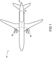
- FIG. 1 A hydrogen-fuelled airliner is illustrated in Figure 1 .
- the airliner 10 is of substantially conventional tube-and-wing twinjet configuration with a central fuselage 12 and a propulsion system comprising substantially identical underwing-mounted turbofan engines 20.
- the hydrogen storage tank 16 is a cryogenic hydrogen storage tank and thus stores the hydrogen fuel in a liquid state, in a specific example at 22 Kelvin.
- the hydrogen fuel is pressurised to a pressure from around 1 bar to around 4 bar, in a specific example 4 bar.
- storing the hydrogen fuel at a higher pressure would necessitate heavier tanks to contain the pressure, and increase the risk of leaks.
- a lower pressure would increase the boiling point of the hydrogen, requiring a lower temperature in the tank, and would risk cavitation in downstream hydrogen plumbing.
- FIG. 2 A block diagram of one of the propulsion systems comprising one of the engines 20 is shown in Figure 2 .
- the turbofan engine 20 comprises a core gas turbine 22.
- the core gas turbine 22 comprises, in fluid flow series, separate low and high-pressure compressors 24, 26, a core combustor 28 and a turbine system comprising high and low-pressure turbines 30, 34.
- the low-pressure compressor 24 is driven by the low-pressure turbine 34 via a low-pressure shaft (not shown) and the high-pressure compressor 26 is driven by the high-pressure turbine 30 via a high-pressure shaft (not shown).
- a fan (not shown) is typically provided to provide propulsive thrust in addition to that generated by the engine core.
- the core gas turbine could be of three-shaft configuration, and / or could comprise a reduction gearbox between the turbine and fan.
- hydrogen fuel is pumped from the hydrogen storage tank 16 by a main, high-pressure hydrogen fuel pump 40 and into a main fuel conduit 42 which ultimately delivers fuel to the core combustor 28.
- the pump 40 is driven by an electric machine.
- the pump 40 may be driven by one or more of the gas turbine engine core shafts via an auxiliary gearbox (not shown).
- a low-pressure pump 44 may also be provided, upstream of the high-pressure pump 40, and may be provided within the liquid hydrogen tank 16.
- the high-pressure hydrogen fuel pump 40 is configured to pump liquid hydrogen, rather than primarily to pump gaseous or supercritical hydrogen. As such, the fluid within the pump 40 is substantially incompressible during operation.
- Suitable pumps include variable displacement pumps such as a centrifugal or axial flow pumps.
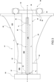
- a first embodiment of an assembly 41 of the high-pressure pump 40 is shown in figure 3 .
- the pump 40 comprises a shaft 46 which is configured to rotate to drive the pump in operation.
- the shaft 46 comprises an elongate axial portion 48, which defines a rotational axis X about which the shaft 46 is configured to rotate.
- the shaft 46 also comprises an aperture 50 at a first axial end, and a shoulder 52 projecting radially from the axial portion at a second axial end.
- a fastener in the form of a threaded bolt 54 is provided.
- the bolt 54 comprises a body comprising an externally threaded portion 56 at the second axial end and an unthreaded portion 58 at the first axial end.
- the bolt also comprises a head 60 located at the first axial end, which projects laterally from the body.
- the externally threaded portion 56 of the bolt 54 is configured to engage against corresponding internal threads (not shown) of the shaft 46.
- the head 60 of the bolt 54 is configured to engage against a first axial surface 64 of an impellor 66 via a spacer 62 provided between the head 60 of the bolt 54 and an axial end of the impellor.
- the impellor 66 in turn comprises a second axial surface 68 on the opposite side to the first axial surface 64, which is configured to engage against the shoulder 52 of the shaft 46.
- a small space 67 may be provided between the bolt head 60 and the first axial end of the shaft 46 to allow for some degree of thermal expansion. The gap also ensures that the shaft 46 and bolt head 60 do not contact during use, ensuring that the axial load path always extends through the bolt head 60, spacer 62 and impellor 66 in use.
- the shaft 46 is rotatably supported in use by a bearing arrangement 80.
- the bearing arrangement provides location and support for the shaft 46 to allow for rotation of the impellor arrangement in use.
- the bearing arrangement comprises an inner race 82, which engages against the shaft 46 or the spacer 62. In some cases, the inner race 82 may form the spacer.
- An outer race 84 is provided, which engages against a mechanical ground.
- Each of the races comprises a suitable bearing material such as Cronidur TM 30. Cronidur 30 is defined in specification AMS5898.
- a bearing 86 such as a roller bearing or ball bearing, is provided between the races 82, 84, and allows for relative rotation thereof.
- the impellor 66 is in the form of a centrifugal impellor, and is configured to rotate to drive fluid from the first axial end of the pump to the second axial end, and centrifugally outward to energise the flow.
- the assembly is assembled as follows.
- the shaft 46 is inserted into a central hollow portion of the impellor 66 until the shoulder 52 engages against the second surface 68 of the impellor 66.
- the spacer 62 (where present) is placed at the end of the impellor 66.
- the bolt 54 is inserted into the aperture 50 until the threaded portion 56 of the bolt 54 engages against the threads of the shaft 46.
- the bolt head 60 is then turned until the head 60 engages against the spacer 62 (where present) and the spacer 62 engages against the impellor 40, and a predetermined torque is achieved.
- the bolt head 60 may engage directly against the impellor 66 where the spacer is not present.
- the impellor assembly is now assembled.
- the impellor assembly can be inserted into a housing (not shown) to complete the pump 40.
- the impellor assembly will experience significant temperature variation. For example, when not in operation, the assembly will typically return to ambient temperature, i.e. between approximately 233 and 323 K. However, when pumping liquid hydrogen, the assembly will be cooled to approximately 20 K. Such large temperature variations may result in the various parts expanding and contracting, which may result in thermal fatigue. This may also result in the thread unlocking, which may cause failure of the assembly.
- liquid hydrogen imposes severe material constraints on the pump assembly.
- the materials used must be compatible both with the chemical properties of hydrogen, and the low temperatures at which the pumps operates. As such, the materials must be resistant to hydrogen embrittlement, and must not become brittle at low temperatures. The materials must also be resistant to fatigue induced by the temperature variations.
- the impellor In order to withstand the high centrifugal loads in use, the impellor must comprise a material having a high ultimate tensile strength.
- the shaft In order to withstand the high centrifugal loads in use, the impellor must comprise a material having a high ultimate tensile strength.
- the shaft In the other hand, the shaft must be compatible with bearing surfaces (in particular, have high hardness), while stress in use tends to be lower. As such, it is desirable to form the shaft and impellor from different materials.
- the bolt 54 and the impellor 66 are made at least in part of a material having a first Coefficient of Thermal Expansion (CTE).
- the shaft 46 and optional spacer 62 are made of a second material having a second CTE which differs to that of the first material.
- the first material has a CTE approximately twice that of the second material.
- at least the unthreaded portion 58 of the body of the bolt 54 comprises the first material.
- at least the elongate portion 48 of the shaft 46 comprises the second material.
- the unthreaded portion 58 of the bolt 54 is free to expand and contract axially, and forms the load path between the head 60 and the threaded portion 56, defining an unconstrained axial length L 1 .
- the elongate portion 48 of the shaft 46 defines the axial extent of contraction and expansion of the shaft 46.
- the impellor 66 is also at least partly formed of the first material.
- the part of the impellor 66 that experiences the clamping loads, and so forms the load path between the bolt heat 60, spacer 62 and the shaft shoulder 52 is formed of the first material, though in the present embodiment, the impellor 66 is unitary, and entirely formed of the first material.
- the impellor 66 axial load path between the two opposite clamping loads i.e. the bolt head 60 or spacer 62 where present, and the shaft shoulder 52
- the first and second lengths L 1 , L 2 are approximately equal to one another, for reasons that will be explained below.
- the first material comprises 316 stainless steel
- the second material comprises S80 stainless steel, as shown in figure 3 .
- S80 is a chromium stainless steel modified by the addition of nickel, and defined by the British Standard Aerospace series of alloys. It is designed to develop high mechanical properties by conventional heat treatment methods and provide good corrosion resistance. This grade is manufactured by electric melting process. Table 1 below gives the composition of this material.
- Table 1 S80 stainless steel has a linear CTE of approximately 6.9 ⁇ 10 -6 K -1 .
- 316 stainless steel is defined by ISO 4404-316-03-I for 316L or 4401.316.00-I for 316, which are listed in BS EN 10088-1.
- 316 stainless steel EN 1.4401 has increased strength and greater creep resistance at higher temperatures compared to 304 stainless steel, and also retains excellent mechanical and corrosion properties at temperatures below 0°C.
- Table 3 below gives the composition: Table 2 316 stainless steel has a linear CTE of approximately 11 ⁇ 10 -6 K -1 . Weight (%) C Mn Si P S Cr Mo Ni N Min 16.0 2.0 10.0 Max 0.08 2.0 0.75 0.045 0.03 18.0 3.0 14.0 0.10
- first and second materials could be used for the first and second materials.
- other grades of stainless steel could be employed which are compatible with hydrogen. Examples are given in PSI PD ISO/TR 15916 "Basic consideration for the safety of hydrogen systems", and include steels such as 310 and A286. Further suitable materials include aluminium and copper.
- the various components will shrink, including in the axial direction X. Since different materials are used in the construction of the assembly, these different materials will shrink to a different degree, which has the potential to result in excessive stress, or reduction in clamping loads which may result in unlocking of the threads 56, and fretting or misalignment of the impellor 66. In view of the high rotational speed of the pump, this may in turn result in damage to the pump.
- the impellor and bolt will reduce in axial length by the same extent during contraction as the temperature falls. Accordingly, the clamping loads are maintained, in spite of the difference in thermal contraction of the impellor 66 and shaft 46. As a result, different materials can be used in the construction of the pump assembly, without encountering problematic differential thermal contraction.
- the use of different materials between the impellors 66 and shaft 46 provides additional advantages. Since the impellors are formed of a material having a higher CTE than the shaft, the impellors will shrink to a greater degree than the shaft when cooled. As a result, the clearance between the impellors 66 and shaft 54 will reduce during cooling, switching from a clearance to an interference fit as the system cools. Consequently, the assembly can be disassembled easily when warm, but is tightly locked in place at normal operating temperatures.
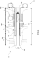
- Figure 4 shows an alternative pump assembly 140 which operates in accordance with similar principles to the first embodiment shown in figure 3 .
- the assembly 140 again comprises a shaft 146, bolt 154, and in this embodiment, first, second and third impellors 166a, 166b, 166c which are arranged in fluid flow series.
- the first impellor 166a differs from the impellor 66 of the first embodiment and the second and third impellors 166b, 166c in that it is an axial flow impellor. Consequently, the impellor 166a is configured to drive flow in a principally axial direction.
- the first impellor 166a is provided upstream in hydrogen flow of the second and third impellors 166b, 166c, and provides an initial head of pressure which aids reduce cavitation in subsequent stages.
- the second and third impellors 166b, 166c are similar to the impellor 66, and are configured to provide the majority of pressure rise in the system.
- a spacer 162 is provided in between the second and third impellors 166b, 166c.
- the arrangement of the shaft 146, bolt 154 and impellors 166a-c is similar to the first embodiment. However, the addition of the further impellors 166a, 166c and the placing of the spacer differentiates this embodiment from the first embodiment.
- the bolt comprises threaded and unthreaded portions 156, 158, which are arranged in a similar manner to the first embodiment.
- the unthreaded portion 158 of the bolt 154 is free to expand and contract axially, and forms the load path between the head 160 and the threaded portion 156, defining an unconstrained axial length L 1 .
- the head 160 of the bolt 154 engages against a first axial surface 170 of the first impellor 166a when assembled.
- the first impellor 166a in turn comprises a second axial surface 172, which engages against a corresponding surface of the second impellor 166b.
- the second impellor 166b in turn comprises a second axial surface 174, which engages against a corresponding surface 174 of the spacer 162.
- the spacer comprises a second axial surface 176 which engages against a corresponding axial surface of the third impellor 166c, which finally engages against an axial surface of the 168 of the shoulder 152 of the shaft 146.
- a clamping load path is defined by the bolt head 160, first and second impellors 166a, 166b, spacer 162, third impellor 166c and shaft shoulder 168 in series, via the axial surfaces 170, 172, 174, 176, 168.
- the assembly is assembled in a similar manner to the first embodiment, with the third impellor 166c, spacer 162, second impellor 166b and first impellor 166a being slid over the shaft 146 prior to insertion of the bolt 154, which is then torqued to the specified value.
- the assembly is mounted on a bearing assembly 180, which engages with the shoulder 152 of the shaft 146.
- the bolt 154 as well as the impellors 166a, 166b, 166c are each formed of a first material, while the spacer 162 and shaft 146 are formed of a second material.
- the first material is 316 stainless steel
- the second material is S80 stainless steel, though again different material choices may be made.
- the clamping load path of the impellors 166a, 166b, 166c is defined by the axial load path extending through lengths L 2a , L 2b , L 2c , and the spacer 162.
- the clamping load path of the bolt 154 is defined by the length L 1 of the unconstrained, unthreaded portion 156.
- the sum of the lengths L 2a , L 2b , L 2c is approximately equal to the length L 1 . Since the spacer 162 is made of the same material as the shaft 146, the impellors 166a-c are made of the same material as the unconstrained length 158 of the bolt 154, and the sum of the lengths L 2a , L 2b , L 2c of the axial load paths of the impellors 166a-c is approximately the same as the length L 1 of the unconstrained region 158 of the bolt 154, the bolt and clamped components contract at the same rate, thereby ensuring consistent clamping loads irrespective of temperature.
- a pump assembly was designed and simulated having an overall length of approximately 100 cm at room temperature (293K).
- a first impellor 166a having an axial clamped length L 2a of 29cm
- a second impellor 166b having an axial clamped length L 2b of 17cm
- a spacer 162 having an axial clamped length of 40cm
- a third impellor 166c having an axial clamped length L 2c of 17cm was provided (all lengths being measured at room temperature). Accordingly, total length L 2a + L 2b + L 2c of 63 cm was defined.
- a bolt having a un threaded portion having an axial length of 57cm.
- the axial length L 1 of the unconstrained length L 1 of the bolt 154 is within 10% of the sum of the lengths L 2a + L 2b + L 2c .
- the length L 1 may be within 20% of the sum of the lengths L 2a + L 2b + L 2c , though in such a case, a higher degree of variation in clamping loads during cooling must be accepted.
- the inventors have found that in such an arrangement, the axial position of the inducer reduces by as much as 0.26 mm when the arrangement is cooled.
- the clamping load is maintained at a constant fixed value, to within less than 0.5% from ambient temperature to operating temperature. Accordingly, strain and therefore fatigue is reduced, and unlocking of the bolt is prevented.
- the fastener could be of a different type. Examples include bayonet fasteners, circlips, adhesive and welding. In each case, the fastener would include first and second engagement points, and an unconstrained length therebetween.
Landscapes
- Engineering & Computer Science (AREA)
- Mechanical Engineering (AREA)
- General Engineering & Computer Science (AREA)
- Structures Of Non-Positive Displacement Pumps (AREA)
Abstract
An impellor assembly (41) for a liquid hydrogen pump (40). The assembly comprises a shaft (46), one or more impellors (66) mounted to the shaft (46), a fastener (54) configured to engage with the shaft (46) at a first engagement point (P1) and with the one or more impellor (66) at a second engagement point (P2) to axially clamp the one or more impellor (66) to the shaft (46), an axially unconstrained length (L1) of the fastener (54) being defined by an axial distance (L1) between the first and second engagement points (P1, P2). An axial extent (L2) of a clamped portion of the one or more impellors (66) corresponds to the axially unconstrained length (L1) of the fastener (46). The fastener (54) and the impellor (66) comprise a material having a first coefficient of thermal expansion and the shaft comprises a material having a second coefficient of thermal expansion, wherein the first and second coefficients of thermal expansion are different.
Description
- This disclosure relates to an impellor assembly for a liquid hydrogen pump for a liquid hydrogen fuelled gas turbine engine. The disclosure also relates to pumps comprising such assemblies, gas turbine engines comprising such pumps, aircraft comprising such gas turbine engines, and methods of assembling pumps utilising such assemblies.
- In order to limit emissions of carbon dioxide, use of hydrogen as an alternative to hydrocarbon fuel in gas turbine engines has historically only been practical in land-based installations. However, more recently there has been interest in aircraft powered by hydrogen stored at cryogenic temperatures, as either a compressed gas, a supercritical fluid, or a liquid.
- One challenge of such systems is the fuel pump. Liquid hydrogen pumps must be tolerant of a wide temperature range, since liquid hydrogen boils at approximately 20 Kelvin (K), but for operational convenience, and also for convenience of assembly, manufacture and servicing of the pump, the pump must be permitted to warm to ambient temperatures between uses. Such a wide temperature range may result in relative thermal expansion of components, which may result in excess stress and short operational life. The present invention seeks to provide a means to address these issues.
- In a first aspect there is provided an impellor assembly for a liquid hydrogen pump, the assembly comprising:
- a shaft;
- one or more impellors mounted to the shaft;
- a fastener configured to engage with the shaft at a first engagement point and with the one or more impellor at a second engagement point to axially clamp the one or more impellor to the shaft, an axially unconstrained portion of the fastener being defined by a region comprising an axial distance between the first and second engagement points and defining a first length; wherein
- an axial extent of a clamped portion of the one or more impellors corresponds to the axially unconstrained length of the fastener; and
- the fastener and the impellor comprise a material having a first coefficient of thermal expansion and the shaft comprises a material having a second coefficient of thermal expansion, wherein the first and second coefficients of thermal expansion are different.
- Advantageously, by providing a fastener formed of a material having the same coefficient of thermal expansion as the impellor, and having an unconstrained length corresponding to the axial length of the impellor, the impellor and shaft can be formed of different materials having different coefficients of thermal expansion, without suffering from relative thermal contraction when the assembly is cooled. Further features and advantages of the disclosed arrangement are set out below.
- The fastener and impellor may be formed of a first material, and the shaft may be formed of a second material.
- The coefficient of thermal expansion of the first material may be higher than that of the second material, and the coefficient of thermal expansion of the first material may be approximately two times that of the second material.
- The fastener may comprise a threaded fastener. The threaded fastener may comprise a threaded portion and an unthreaded portion. The threaded portion may be spaced from a head of the fastener by the unthreaded portion, which may comprise the unconstrained length. Advantageously, the unthreaded portion is able to expand and contract axially during heating and cooling.
- The threaded portion of the fastener may engage against a threaded portion of the shaft. The threaded portion of the fastener may comprise an external thread, and the threaded portion of the shaft may comprise an internal thread.
- A head of the fastener may engage against the impellor at the second engagement point comprising a first axial surface of the impellor. A shoulder of the shaft may engage against a second axial surface of the one or more impellor, opposite the first axial surface.
- The impellor assembly may comprise a bearing arrangement configured to rotatably support the shaft. The bearing arrangement may comprise a bearing mounted to a bearing race. The bearing race may comprise a material having approximately the same coefficient of thermal expansion as the material of the shaft.
- The impellor and fastener may comprise one of 316L stainless steel and aluminium. The shaft may comprise S80 stainless steel. The bearing race may comprise Cronidur™ 30.
- The impellor assembly may comprise a first impellor and a second impellor. A first axial surface of the first impellor may engage against a head of the fastener, a second axial surface of the first impellor may engage against a first axial surface of the second impellor, and a second axial surface of the second impellor may engage against a shoulder of the shaft.
- The impellor assembly may comprise first, second and third impellors. Each of the impellors may comprise the first material. A first axial surface of the first impellor may engage against a head of the fastener, a second axial surface of the first impellor may engage against a first axial surface of the second impellor, a second axial surface of the second impellor may engage against a spacer, the spacer may engage against a first axial surface of the third impellor, and a second axial surface of the third impellor may engage against a shoulder of the shaft.
- The spacer may comprise the second material.
- The impellor may comprise one of an axial pump impellor and a centrifugal pump impellor. In one embodiment, the first impellor comprises an axial pump impellor and the second impellor comprises a centrifugal pump impellor.
- In a second aspect, there is provided a liquid hydrogen pump comprising an impellor assembly according to the first aspect and a housing.
- In a third aspect there is provided an aircraft propulsion system comprising a gas turbine engine and a liquid hydrogen fuel pump according to the second aspect.
- In a fourth aspect there is provided an aircraft comprising a propulsion system according to the third aspect.
- In a fifth aspect there is provided a method of assembly of an impellor assembly for a liquid hydrogen pump, the method comprising:
- providing an impellor assembly according to the first aspect; and
- using the fastener to axially clamp the impellor to the shaft.
- An embodiment will now be described by way of example only with reference to the accompanying drawings, which are purely schematic and not to scale, and in which:
-
Figure 1 shows a hydrogen-fuelled airliner comprising a propulsion system comprising hydrogen-fuelled turbofan engines; -
Figure 2 is a block diagram of a fuel system of the propulsion system of the aircraft offigure 1 ; -
Figure 3 is a cross-sectional view of part of a fuel pump of the fuel system offigure 2 ; and -
Figure 4 is a cross-sectional view of part of an alternative fuel pump for the fuel system offigure 2 . - A hydrogen-fuelled airliner is illustrated in
Figure 1 . In this example, theairliner 10 is of substantially conventional tube-and-wing twinjet configuration with acentral fuselage 12 and a propulsion system comprising substantially identical underwing-mountedturbofan engines 20. - A
hydrogen storage tank 16 located in thefuselage 12. Thehydrogen storage tank 16 is a cryogenic hydrogen storage tank and thus stores the hydrogen fuel in a liquid state, in a specific example at 22 Kelvin. In this example, the hydrogen fuel is pressurised to a pressure from around 1 bar to around 4 bar, in a specific example 4 bar. As will be appreciated, storing the hydrogen fuel at a higher pressure would necessitate heavier tanks to contain the pressure, and increase the risk of leaks. On the other hand, a lower pressure would increase the boiling point of the hydrogen, requiring a lower temperature in the tank, and would risk cavitation in downstream hydrogen plumbing. - A block diagram of one of the propulsion systems comprising one of the
engines 20 is shown inFigure 2 . - The
turbofan engine 20 comprises acore gas turbine 22. - The
core gas turbine 22 comprises, in fluid flow series, separate low and high-pressure compressors core combustor 28 and a turbine system comprising high and low-pressure turbines pressure compressor 24 is driven by the low-pressure turbine 34 via a low-pressure shaft (not shown) and the high-pressure compressor 26 is driven by the high-pressure turbine 30 via a high-pressure shaft (not shown). A fan (not shown) is typically provided to provide propulsive thrust in addition to that generated by the engine core. It will be appreciated that in alternative embodiments, the core gas turbine could be of three-shaft configuration, and / or could comprise a reduction gearbox between the turbine and fan. - In operation, hydrogen fuel is pumped from the
hydrogen storage tank 16 by a main, high-pressurehydrogen fuel pump 40 and into amain fuel conduit 42 which ultimately delivers fuel to thecore combustor 28. In the present embodiment, thepump 40 is driven by an electric machine. In other embodiments, thepump 40 may be driven by one or more of the gas turbine engine core shafts via an auxiliary gearbox (not shown). In some cases, a low-pressure pump 44 may also be provided, upstream of the high-pressure pump 40, and may be provided within theliquid hydrogen tank 16. - The high-pressure
hydrogen fuel pump 40 is configured to pump liquid hydrogen, rather than primarily to pump gaseous or supercritical hydrogen. As such, the fluid within thepump 40 is substantially incompressible during operation. Suitable pumps include variable displacement pumps such as a centrifugal or axial flow pumps. - A first embodiment of an
assembly 41 of the high-pressure pump 40 is shown infigure 3 . - The
pump 40 comprises ashaft 46 which is configured to rotate to drive the pump in operation. Theshaft 46 comprises an elongateaxial portion 48, which defines a rotational axis X about which theshaft 46 is configured to rotate. Theshaft 46 also comprises anaperture 50 at a first axial end, and ashoulder 52 projecting radially from the axial portion at a second axial end. - A fastener in the form of a threaded
bolt 54 is provided. Thebolt 54 comprises a body comprising an externally threadedportion 56 at the second axial end and an unthreadedportion 58 at the first axial end. The bolt also comprises ahead 60 located at the first axial end, which projects laterally from the body. The externally threadedportion 56 of thebolt 54 is configured to engage against corresponding internal threads (not shown) of theshaft 46. - The
head 60 of thebolt 54 is configured to engage against a firstaxial surface 64 of animpellor 66 via aspacer 62 provided between thehead 60 of thebolt 54 and an axial end of the impellor. Theimpellor 66 in turn comprises a secondaxial surface 68 on the opposite side to the firstaxial surface 64, which is configured to engage against theshoulder 52 of theshaft 46. Asmall space 67 may be provided between thebolt head 60 and the first axial end of theshaft 46 to allow for some degree of thermal expansion. The gap also ensures that theshaft 46 andbolt head 60 do not contact during use, ensuring that the axial load path always extends through thebolt head 60,spacer 62 andimpellor 66 in use. - The
shaft 46 is rotatably supported in use by a bearingarrangement 80. The bearing arrangement provides location and support for theshaft 46 to allow for rotation of the impellor arrangement in use. The bearing arrangement comprises aninner race 82, which engages against theshaft 46 or thespacer 62. In some cases, theinner race 82 may form the spacer. Anouter race 84 is provided, which engages against a mechanical ground. Each of the races comprises a suitable bearing material such asCronidur ™ 30.Cronidur 30 is defined in specification AMS5898. Abearing 86, such as a roller bearing or ball bearing, is provided between theraces impellor 66 is in the form of a centrifugal impellor, and is configured to rotate to drive fluid from the first axial end of the pump to the second axial end, and centrifugally outward to energise the flow. - The assembly is assembled as follows. The
shaft 46 is inserted into a central hollow portion of theimpellor 66 until theshoulder 52 engages against thesecond surface 68 of theimpellor 66. The spacer 62 (where present) is placed at the end of theimpellor 66. Thebolt 54 is inserted into theaperture 50 until the threadedportion 56 of thebolt 54 engages against the threads of theshaft 46. Thebolt head 60 is then turned until thehead 60 engages against the spacer 62 (where present) and thespacer 62 engages against theimpellor 40, and a predetermined torque is achieved. Alternatively, thebolt head 60 may engage directly against theimpellor 66 where the spacer is not present. The impellor assembly is now assembled. The impellor assembly can be inserted into a housing (not shown) to complete thepump 40. - During service, the impellor assembly will experience significant temperature variation. For example, when not in operation, the assembly will typically return to ambient temperature, i.e. between approximately 233 and 323 K. However, when pumping liquid hydrogen, the assembly will be cooled to approximately 20 K. Such large temperature variations may result in the various parts expanding and contracting, which may result in thermal fatigue. This may also result in the thread unlocking, which may cause failure of the assembly.
- This is particularly problematic where the pump assembly comprises dissimilar materials, as in the present disclosure.
- As will be understood, liquid hydrogen imposes severe material constraints on the pump assembly. The materials used must be compatible both with the chemical properties of hydrogen, and the low temperatures at which the pumps operates. As such, the materials must be resistant to hydrogen embrittlement, and must not become brittle at low temperatures. The materials must also be resistant to fatigue induced by the temperature variations.
- Additional material requirements also exist for the different components. In order to withstand the high centrifugal loads in use, the impellor must comprise a material having a high ultimate tensile strength. On the other hand, the shaft must be compatible with bearing surfaces (in particular, have high hardness), while stress in use tends to be lower. As such, it is desirable to form the shaft and impellor from different materials.
- The
bolt 54 and theimpellor 66 are made at least in part of a material having a first Coefficient of Thermal Expansion (CTE). Theshaft 46 andoptional spacer 62 are made of a second material having a second CTE which differs to that of the first material. In the present disclosure, the first material has a CTE approximately twice that of the second material. In particular, at least the unthreadedportion 58 of the body of thebolt 54 comprises the first material. Similarly, at least theelongate portion 48 of theshaft 46 comprises the second material. As will be understood, the unthreadedportion 58 of thebolt 54 is free to expand and contract axially, and forms the load path between thehead 60 and the threadedportion 56, defining an unconstrained axial length L1. Similarly, theelongate portion 48 of theshaft 46 defines the axial extent of contraction and expansion of theshaft 46. - The
impellor 66 is also at least partly formed of the first material. In particular, the part of theimpellor 66 that experiences the clamping loads, and so forms the load path between thebolt heat 60,spacer 62 and theshaft shoulder 52 is formed of the first material, though in the present embodiment, theimpellor 66 is unitary, and entirely formed of the first material. Theimpellor 66 axial load path between the two opposite clamping loads (i.e. thebolt head 60 orspacer 62 where present, and the shaft shoulder 52) defines a second axial length L2. The first and second lengths L1, L2 are approximately equal to one another, for reasons that will be explained below. - In one example, the first material comprises 316 stainless steel, and the second material comprises S80 stainless steel, as shown in
figure 3 . - S80 is a chromium stainless steel modified by the addition of nickel, and defined by the British Standard Aerospace series of alloys. It is designed to develop high mechanical properties by conventional heat treatment methods and provide good corrosion resistance. This grade is manufactured by electric melting process. Table 1 below gives the composition of this material.
Table 1 S80 stainless steel has a linear CTE of approximately 6.9×10⁻⁶ K-1. Weight (%) C Si Mn P S Cr Ni Min 0.12 15.0 2.0 Max 0.20 1.0 1.0 0.030 0.025 18.0 3.0 - 316 stainless steel, is defined by ISO 4404-316-03-I for 316L or 4401.316.00-I for 316, which are listed in BS EN 10088-1. 316 stainless steel EN 1.4401 has increased strength and greater creep resistance at higher temperatures compared to 304 stainless steel, and also retains excellent mechanical and corrosion properties at temperatures below 0°C. Table 3 below gives the composition:
Table 2 316 stainless steel has a linear CTE of approximately 11×10-6 K-1. Weight (%) C Mn Si P S Cr Mo Ni N Min 16.0 2.0 10.0 Max 0.08 2.0 0.75 0.045 0.03 18.0 3.0 14.0 0.10 - As will be understood, alternative materials could be used for the first and second materials. For example, other grades of stainless steel could be employed which are compatible with hydrogen. Examples are given in PSI PD ISO/TR 15916 "Basic consideration for the safety of hydrogen systems", and include steels such as 310 and A286. Further suitable materials include aluminium and copper.
- As will be understood, when the pump assembly is cooled from an ambient temperature of approximately 273 to 323K (0 to 40C) to an operating temperature of around 20 to 30K, the various components will shrink, including in the axial direction X. Since different materials are used in the construction of the assembly, these different materials will shrink to a different degree, which has the potential to result in excessive stress, or reduction in clamping loads which may result in unlocking of the
threads 56, and fretting or misalignment of theimpellor 66. In view of the high rotational speed of the pump, this may in turn result in damage to the pump. - However, as a result of the arrangement of the lengths L1, L2 being approximately equal and the
bolt 54 andimpellor 66 being made of the same material, the impellor and bolt will reduce in axial length by the same extent during contraction as the temperature falls. Accordingly, the clamping loads are maintained, in spite of the difference in thermal contraction of theimpellor 66 andshaft 46. As a result, different materials can be used in the construction of the pump assembly, without encountering problematic differential thermal contraction. - The use of different materials between the
impellors 66 andshaft 46 provides additional advantages. Since the impellors are formed of a material having a higher CTE than the shaft, the impellors will shrink to a greater degree than the shaft when cooled. As a result, the clearance between theimpellors 66 andshaft 54 will reduce during cooling, switching from a clearance to an interference fit as the system cools. Consequently, the assembly can be disassembled easily when warm, but is tightly locked in place at normal operating temperatures. -
Figure 4 shows analternative pump assembly 140 which operates in accordance with similar principles to the first embodiment shown infigure 3 . - The
assembly 140 again comprises ashaft 146,bolt 154, and in this embodiment, first, second andthird impellors - The
first impellor 166a differs from theimpellor 66 of the first embodiment and the second andthird impellors impellor 166a is configured to drive flow in a principally axial direction. Thefirst impellor 166a is provided upstream in hydrogen flow of the second andthird impellors - The second and
third impellors impellor 66, and are configured to provide the majority of pressure rise in the system. Aspacer 162 is provided in between the second andthird impellors - As can be seen from
figure 4 , the arrangement of theshaft 146,bolt 154 andimpellors 166a-c is similar to the first embodiment. However, the addition of thefurther impellors - As in the previous embodiment, the bolt comprises threaded and
unthreaded portions portion 158 of thebolt 154 is free to expand and contract axially, and forms the load path between thehead 160 and the threadedportion 156, defining an unconstrained axial length L1. - The
head 160 of thebolt 154 engages against a firstaxial surface 170 of thefirst impellor 166a when assembled. Thefirst impellor 166a in turn comprises a secondaxial surface 172, which engages against a corresponding surface of thesecond impellor 166b. Thesecond impellor 166b in turn comprises a secondaxial surface 174, which engages against acorresponding surface 174 of thespacer 162. The spacer comprises a secondaxial surface 176 which engages against a corresponding axial surface of thethird impellor 166c, which finally engages against an axial surface of the 168 of theshoulder 152 of theshaft 146. Consequently, a clamping load path is defined by thebolt head 160, first andsecond impellors spacer 162,third impellor 166c andshaft shoulder 168 in series, via theaxial surfaces - The assembly is assembled in a similar manner to the first embodiment, with the
third impellor 166c,spacer 162,second impellor 166b andfirst impellor 166a being slid over theshaft 146 prior to insertion of thebolt 154, which is then torqued to the specified value. Again, the assembly is mounted on abearing assembly 180, which engages with theshoulder 152 of theshaft 146. - As in the previous embodiment, the
bolt 154 as well as the impellors 166a, 166b, 166c are each formed of a first material, while thespacer 162 andshaft 146 are formed of a second material. In this embodiment, the first material is 316 stainless steel, while the second material is S80 stainless steel, though again different material choices may be made. - In this case, the clamping load path of the impellors 166a, 166b, 166c is defined by the axial load path extending through lengths L2a, L2b, L2c, and the
spacer 162. Similarly, the clamping load path of thebolt 154 is defined by the length L1 of the unconstrained,unthreaded portion 156. - In this embodiment, the sum of the lengths L2a, L2b, L2c is approximately equal to the length L1. Since the
spacer 162 is made of the same material as theshaft 146, theimpellors 166a-c are made of the same material as theunconstrained length 158 of thebolt 154, and the sum of the lengths L2a, L2b, L2c of the axial load paths of theimpellors 166a-c is approximately the same as the length L1 of theunconstrained region 158 of thebolt 154, the bolt and clamped components contract at the same rate, thereby ensuring consistent clamping loads irrespective of temperature. - In one example tested by the inventors, a pump assembly was designed and simulated having an overall length of approximately 100 cm at room temperature (293K). A
first impellor 166a having an axial clamped length L2a of 29cm, asecond impellor 166b having an axial clamped length L2b of 17cm, aspacer 162 having an axial clamped length of 40cm, and athird impellor 166c having an axial clamped length L2c of 17cm was provided (all lengths being measured at room temperature). Accordingly, total length L2a + L2b + L2c of 63 cm was defined. A bolt having a un threaded portion having an axial length of 57cm. Accordingly, the axial length L1 of the unconstrained length L1 of thebolt 154 is within 10% of the sum of the lengths L2a + L2b + L2c. In other embodiments, the length L1 may be within 20% of the sum of the lengths L2a + L2b + L2c, though in such a case, a higher degree of variation in clamping loads during cooling must be accepted. - The inventors have found that in such an arrangement, the axial position of the inducer reduces by as much as 0.26 mm when the arrangement is cooled. However, the clamping load is maintained at a constant fixed value, to within less than 0.5% from ambient temperature to operating temperature. Accordingly, strain and therefore fatigue is reduced, and unlocking of the bolt is prevented.
- Various examples have been described, each of which comprise various combinations of features. It will be appreciated by those skilled in the art that, except where clearly mutually exclusive, any of the features may be employed separately or in combination with any other features and thus the disclosed subject-matter extends to and includes all such combinations and sub-combinations of the or more features described herein.
- Changes may be made to the disclosed embodiment without departing from the invention as defined by the claims. For example, the fastener could be of a different type. Examples include bayonet fasteners, circlips, adhesive and welding. In each case, the fastener would include first and second engagement points, and an unconstrained length therebetween.
Claims (15)
- An impellor assembly (41) for a liquid hydrogen pump (40), the assembly comprising:a shaft (46);one or more impellors (66) mounted to the shaft (46);a fastener (54) configured to engage with the shaft (46) at a first engagement point (P1) and with the one or more impellor (66) at a second engagement point (P2) to axially clamp the one or more impellor (66) to the shaft (46), an axially unconstrained length (L1) of the fastener (54) being defined by an axial distance (L1) between the first and second engagement points (P1, P2); whereinan axial extent (L2) of a clamped portion of the one or more impellors (66) corresponds to the axially unconstrained length (L1) of the fastener (54); andthe fastener (54) and the impellor (66) comprise a material having a first coefficient of thermal expansion and the shaft comprises a material having a second coefficient of thermal expansion, wherein the first and second coefficients of thermal expansion are different.
- An impellor assembly according to claim 1, wherein fastener (54) and impellor (66) are formed of a first material, and the shaft (46) is formed of a second material.
- An impellor assembly according to claim 2, wherein the coefficient of thermal expansion of the first material is higher than that of the second material, and the coefficient of thermal expansion of the first material may be approximately two times that of the second material.
- An impellor assembly according to any preceding claim, wherein the fastener (54) comprises a threaded fastener comprising a threaded portion (56) and an unthreaded portion (58), and wherein the threaded portion (56) may be spaced from a head (60) of the fastener (54) by the unthreaded portion (58), which may comprise the unconstrained length (L1).
- An impellor assembly according to claim 4, wherein the threaded portion (56) of the fastener (54) engages against a threaded portion of the shaft (46).
- An impellor assembly according to claim 4 or claim 5, wherein the head (60) of the fastener (54) engages against the impellor (66) at the second engagement point (P2) comprising a first axial surface (64) of the impellor (66), and wherein a shoulder (52) of the shaft (46) may engage against a second axial surface (68) of the one or more impellor (66), opposite the first axial surface (64).
- An impellor assembly according to any preceding claim comprising a bearing arrangement (80) configured to rotatably support the shaft (46), and wherein the bearing arrangement (80) may comprise a bearing (86) mounted to a bearing race (82), the bearing race (82) comprising a material having approximately the same coefficient of thermal expansion as the material of the shaft (46).
- An impellor assembly according to any preceding claim, wherein the impellor (66) and fastener (54) comprise one of 316L stainless steel and aluminium.
- An impellor assembly according to any preceding claim, wherein the shaft (46) comprises S80 stainless steel.
- An impellor assembly according to claim 7 or any claim dependent thereon, wherein the bearing race (82) comprises Cronidur™ 30.
- An impellor assembly according to any preceding claim comprising a first impellor (166a) and a second impellor (166b), wherein a first axial surface (170) of the first impellor (166a) may engages against a head (170) of the fastener (154), a second axial surface (172) of the first impellor (166a) engage against a first axial surface of the second impellor (166b), and a second axial surface (174) of the second impellor (166b) may engage against a shoulder (168) of the shaft (146).
- An impellor assembly according to any of the preceding claims comprising first (166a), second (166b) and third (166c) impellors, and each of the impellors (166a-c) may comprise the first material.
- An impellor assembly according to claim 12, wherein first axial surface (170) of the first impellor (166a) engages against a head (170) of the fastener (154), a second axial surface (172) of the first impellor (166a) engages against a first axial surface (172) of the second impellor (166b), a second axial surface (174) of the second impellor (166b) engages against a spacer (162), the spacer (162) engages against a first axial surface (176) of the third impellor (166c), and a second axial surface of the third impellor (166c) engages against a shoulder (168) of the shaft (146), and wherein the spacer (162) may comprise the second material.
- A liquid hydrogen pump (40) comprising an impellor assembly (41) according to any preceding claim, and a housing.
- A method of assembly of an impellor assembly (41) for a liquid hydrogen pump (40), the method comprising:providing an impellor assembly in accordance with any of the preceding claims; andusing the fastener (54) to axially clamp the impellor (66) to the shaft (46).
Applications Claiming Priority (1)
| Application Number | Priority Date | Filing Date | Title |
|---|---|---|---|
| GB202317640 | 2023-11-17 |
Publications (1)
| Publication Number | Publication Date |
|---|---|
| EP4556719A1 true EP4556719A1 (en) | 2025-05-21 |
Family
ID=93154351
Family Applications (1)
| Application Number | Title | Priority Date | Filing Date |
|---|---|---|---|
| EP24207101.7A Pending EP4556719A1 (en) | 2023-11-17 | 2024-10-17 | Liquid hydrogen pump impellor assembly |
Country Status (2)
| Country | Link |
|---|---|
| US (1) | US20250163928A1 (en) |
| EP (1) | EP4556719A1 (en) |
Citations (6)
| Publication number | Priority date | Publication date | Assignee | Title |
|---|---|---|---|---|
| US4183719A (en) * | 1976-05-13 | 1980-01-15 | Maschinenfabrik Augsburg-Nurnberg Aktiengesellschaft (MAN) | Composite impeller wheel with improved centering of one component on the other |
| JPS5918201A (en) * | 1982-07-23 | 1984-01-30 | Nissan Motor Co Ltd | Fitting structure of ceramics turbine |
| US5286162A (en) * | 1993-01-04 | 1994-02-15 | The United States Of America As Represented By The Administrator Of The National Aeronautics And Space Administration | Method of reducing hydraulic instability |
| US6012901A (en) * | 1997-09-19 | 2000-01-11 | Asea Brown Boveri Ag | Compressor impeller fastening for high speed turboengines |
| DE102016119233A1 (en) * | 2016-10-10 | 2018-04-12 | Ihi Charging Systems International Gmbh | Tool for an exhaust gas turbocharger and turbocharger |
| EP3929405A1 (en) * | 2020-06-22 | 2021-12-29 | Galileo Technologies Corporation | Microturbine power generating system and method of assembly |
Family Cites Families (10)
| Publication number | Priority date | Publication date | Assignee | Title |
|---|---|---|---|---|
| US5529464A (en) * | 1988-07-12 | 1996-06-25 | Alliedsignal Inc. | Cryogenic turbopump |
| US6896479B2 (en) * | 2003-04-08 | 2005-05-24 | General Motors Corporation | Turbocharger rotor |
| IT1399904B1 (en) * | 2010-04-21 | 2013-05-09 | Nuovo Pignone Spa | STACKED ROTOR WITH TIE AND BOLTED FLANGE AND METHOD |
| CN102767398A (en) * | 2012-07-04 | 2012-11-07 | 联优机械(常熟)有限公司 | Impeller and main shaft matched structure of turbo expander |
| WO2014088824A1 (en) * | 2012-12-06 | 2014-06-12 | Borgwarner Inc. | Exhaust-gas turbocharger |
| DE102016204301A1 (en) * | 2016-03-16 | 2017-09-21 | Schaeffler Technologies AG & Co. KG | Pump device, in particular for a coolant pump and vehicle with the pump device |
| US11009035B2 (en) * | 2018-04-25 | 2021-05-18 | Aktiebolaget Skf | Two hybrid ball bearings and a compressor bearing arrangement |
| US11401942B2 (en) * | 2020-05-15 | 2022-08-02 | Garrett Transportation I Inc | Fastener arrangement for rotating group of turbomachine |
| JP7558083B2 (en) * | 2021-02-25 | 2024-09-30 | 三菱重工コンプレッサ株式会社 | Compressor |
| KR102570042B1 (en) * | 2021-03-04 | 2023-08-23 | 세드나이엔지(주) | Magnetic pump |
-
2024
- 2024-10-17 EP EP24207101.7A patent/EP4556719A1/en active Pending
- 2024-10-25 US US18/927,055 patent/US20250163928A1/en active Pending
Patent Citations (6)
| Publication number | Priority date | Publication date | Assignee | Title |
|---|---|---|---|---|
| US4183719A (en) * | 1976-05-13 | 1980-01-15 | Maschinenfabrik Augsburg-Nurnberg Aktiengesellschaft (MAN) | Composite impeller wheel with improved centering of one component on the other |
| JPS5918201A (en) * | 1982-07-23 | 1984-01-30 | Nissan Motor Co Ltd | Fitting structure of ceramics turbine |
| US5286162A (en) * | 1993-01-04 | 1994-02-15 | The United States Of America As Represented By The Administrator Of The National Aeronautics And Space Administration | Method of reducing hydraulic instability |
| US6012901A (en) * | 1997-09-19 | 2000-01-11 | Asea Brown Boveri Ag | Compressor impeller fastening for high speed turboengines |
| DE102016119233A1 (en) * | 2016-10-10 | 2018-04-12 | Ihi Charging Systems International Gmbh | Tool for an exhaust gas turbocharger and turbocharger |
| EP3929405A1 (en) * | 2020-06-22 | 2021-12-29 | Galileo Technologies Corporation | Microturbine power generating system and method of assembly |
Also Published As
| Publication number | Publication date |
|---|---|
| US20250163928A1 (en) | 2025-05-22 |
Similar Documents
| Publication | Publication Date | Title |
|---|---|---|
| US8573922B2 (en) | Bearing support | |
| EP2964968B1 (en) | Linkage apparatus having a low profile asymmetrical head | |
| US20080148708A1 (en) | Turbine engine system with shafts for improved weight and vibration characteristic | |
| US9506403B2 (en) | Fastener | |
| US7470115B2 (en) | Outer diameter nut piloting for improved rotor balance | |
| EP3992434B1 (en) | Service tube assembly for a gas turbine engine | |
| CN109312667B (en) | Air turbine starter with decoupler | |
| US20120180494A1 (en) | Turbine fuel nozzle assembly | |
| US10330145B2 (en) | Gear pump bearing | |
| US20090060706A1 (en) | Ball bearing and pump for cryogenic use | |
| EP2698567A1 (en) | Intershaft seal | |
| US10876430B2 (en) | Mount assembly | |
| US20250163928A1 (en) | Liquid hydrogen pump impellor assembly | |
| US10294985B2 (en) | Gear pump bearing | |
| US20200347970A1 (en) | Low profile flexible coupling and tool for assembling flexible couplings | |
| US8864406B2 (en) | Splined couplings | |
| EP3453903B1 (en) | Gear pump bearing | |
| US20160108818A1 (en) | Fluid conduit | |
| KR20230166106A (en) | Elements, devices and methods for compressing gases to be compressed having low temperatures | |
| US20110129327A1 (en) | Ball bearing and pump for cryogenic use | |
| CN114198208A (en) | Air turbine starter | |
| EP3613945B1 (en) | Displacement pump | |
| US20130129501A1 (en) | Stud retention | |
| US8684681B2 (en) | Air cycle machine composite insulator plate | |
| US12601262B1 (en) | Gas turbine engines, methods of securing rotating components therein with threaded nuts, and the threaded nuts |
Legal Events
| Date | Code | Title | Description |
|---|---|---|---|
| PUAI | Public reference made under article 153(3) epc to a published international application that has entered the european phase |
Free format text: ORIGINAL CODE: 0009012 |
|
| STAA | Information on the status of an ep patent application or granted ep patent |
Free format text: STATUS: THE APPLICATION HAS BEEN PUBLISHED |
|
| AK | Designated contracting states |
Kind code of ref document: A1 Designated state(s): AL AT BE BG CH CY CZ DE DK EE ES FI FR GB GR HR HU IE IS IT LI LT LU LV MC ME MK MT NL NO PL PT RO RS SE SI SK SM TR |
|
| STAA | Information on the status of an ep patent application or granted ep patent |
Free format text: STATUS: REQUEST FOR EXAMINATION WAS MADE |
|
| 17P | Request for examination filed |
Effective date: 20250606 |