EP4556697A2 - Fluidic compressor inlet guide vanes - Google Patents
Fluidic compressor inlet guide vanes Download PDFInfo
- Publication number
- EP4556697A2 EP4556697A2 EP24213392.4A EP24213392A EP4556697A2 EP 4556697 A2 EP4556697 A2 EP 4556697A2 EP 24213392 A EP24213392 A EP 24213392A EP 4556697 A2 EP4556697 A2 EP 4556697A2
- Authority
- EP
- European Patent Office
- Prior art keywords
- compressor
- waterflow
- injectors
- intercooling
- passage
- Prior art date
- Legal status (The legal status is an assumption and is not a legal conclusion. Google has not performed a legal analysis and makes no representation as to the accuracy of the status listed.)
- Pending
Links
Images


Classifications
-
- F—MECHANICAL ENGINEERING; LIGHTING; HEATING; WEAPONS; BLASTING
- F02—COMBUSTION ENGINES; HOT-GAS OR COMBUSTION-PRODUCT ENGINE PLANTS
- F02C—GAS-TURBINE PLANTS; AIR INTAKES FOR JET-PROPULSION PLANTS; CONTROLLING FUEL SUPPLY IN AIR-BREATHING JET-PROPULSION PLANTS
- F02C7/00—Features, components parts, details or accessories, not provided for in, or of interest apart form groups F02C1/00 - F02C6/00; Air intakes for jet-propulsion plants
- F02C7/12—Cooling of plants
- F02C7/14—Cooling of plants of fluids in the plant, e.g. lubricant or fuel
- F02C7/141—Cooling of plants of fluids in the plant, e.g. lubricant or fuel of working fluid
- F02C7/143—Cooling of plants of fluids in the plant, e.g. lubricant or fuel of working fluid before or between the compressor stages
- F02C7/1435—Cooling of plants of fluids in the plant, e.g. lubricant or fuel of working fluid before or between the compressor stages by water injection
-
- B—PERFORMING OPERATIONS; TRANSPORTING
- B64—AIRCRAFT; AVIATION; COSMONAUTICS
- B64D—EQUIPMENT FOR FITTING IN OR TO AIRCRAFT; FLIGHT SUITS; PARACHUTES; ARRANGEMENT OR MOUNTING OF POWER PLANTS OR PROPULSION TRANSMISSIONS IN AIRCRAFT
- B64D33/00—Arrangement in aircraft of power plant parts or auxiliaries not otherwise provided for
- B64D33/08—Arrangement in aircraft of power plant parts or auxiliaries not otherwise provided for of power plant cooling systems
-
- F—MECHANICAL ENGINEERING; LIGHTING; HEATING; WEAPONS; BLASTING
- F02—COMBUSTION ENGINES; HOT-GAS OR COMBUSTION-PRODUCT ENGINE PLANTS
- F02C—GAS-TURBINE PLANTS; AIR INTAKES FOR JET-PROPULSION PLANTS; CONTROLLING FUEL SUPPLY IN AIR-BREATHING JET-PROPULSION PLANTS
- F02C3/00—Gas-turbine plants characterised by the use of combustion products as the working fluid
- F02C3/20—Gas-turbine plants characterised by the use of combustion products as the working fluid using a special fuel, oxidant, or dilution fluid to generate the combustion products
- F02C3/22—Gas-turbine plants characterised by the use of combustion products as the working fluid using a special fuel, oxidant, or dilution fluid to generate the combustion products the fuel or oxidant being gaseous at standard temperature and pressure
-
- F—MECHANICAL ENGINEERING; LIGHTING; HEATING; WEAPONS; BLASTING
- F02—COMBUSTION ENGINES; HOT-GAS OR COMBUSTION-PRODUCT ENGINE PLANTS
- F02C—GAS-TURBINE PLANTS; AIR INTAKES FOR JET-PROPULSION PLANTS; CONTROLLING FUEL SUPPLY IN AIR-BREATHING JET-PROPULSION PLANTS
- F02C3/00—Gas-turbine plants characterised by the use of combustion products as the working fluid
- F02C3/20—Gas-turbine plants characterised by the use of combustion products as the working fluid using a special fuel, oxidant, or dilution fluid to generate the combustion products
- F02C3/30—Adding water, steam or other fluids for influencing combustion, e.g. to obtain cleaner exhaust gases
- F02C3/305—Increasing the power, speed, torque or efficiency of a gas turbine or the thrust of a turbojet engine by injecting or adding water, steam or other fluids
-
- F—MECHANICAL ENGINEERING; LIGHTING; HEATING; WEAPONS; BLASTING
- F02—COMBUSTION ENGINES; HOT-GAS OR COMBUSTION-PRODUCT ENGINE PLANTS
- F02C—GAS-TURBINE PLANTS; AIR INTAKES FOR JET-PROPULSION PLANTS; CONTROLLING FUEL SUPPLY IN AIR-BREATHING JET-PROPULSION PLANTS
- F02C7/00—Features, components parts, details or accessories, not provided for in, or of interest apart form groups F02C1/00 - F02C6/00; Air intakes for jet-propulsion plants
- F02C7/12—Cooling of plants
- F02C7/14—Cooling of plants of fluids in the plant, e.g. lubricant or fuel
- F02C7/141—Cooling of plants of fluids in the plant, e.g. lubricant or fuel of working fluid
-
- F—MECHANICAL ENGINEERING; LIGHTING; HEATING; WEAPONS; BLASTING
- F02—COMBUSTION ENGINES; HOT-GAS OR COMBUSTION-PRODUCT ENGINE PLANTS
- F02C—GAS-TURBINE PLANTS; AIR INTAKES FOR JET-PROPULSION PLANTS; CONTROLLING FUEL SUPPLY IN AIR-BREATHING JET-PROPULSION PLANTS
- F02C7/00—Features, components parts, details or accessories, not provided for in, or of interest apart form groups F02C1/00 - F02C6/00; Air intakes for jet-propulsion plants
- F02C7/12—Cooling of plants
- F02C7/14—Cooling of plants of fluids in the plant, e.g. lubricant or fuel
- F02C7/141—Cooling of plants of fluids in the plant, e.g. lubricant or fuel of working fluid
- F02C7/143—Cooling of plants of fluids in the plant, e.g. lubricant or fuel of working fluid before or between the compressor stages
-
- F—MECHANICAL ENGINEERING; LIGHTING; HEATING; WEAPONS; BLASTING
- F05—INDEXING SCHEMES RELATING TO ENGINES OR PUMPS IN VARIOUS SUBCLASSES OF CLASSES F01-F04
- F05D—INDEXING SCHEME FOR ASPECTS RELATING TO NON-POSITIVE-DISPLACEMENT MACHINES OR ENGINES, GAS-TURBINES OR JET-PROPULSION PLANTS
- F05D2260/00—Function
- F05D2260/20—Heat transfer, e.g. cooling
- F05D2260/211—Heat transfer, e.g. cooling by intercooling, e.g. during a compression cycle
Definitions
- the present disclosure relates generally to an intercooled turbine engine where water is injected into a compressor section.
- Gas turbine engines compress incoming core airflow, mix the compressed airflow with fuel that is ignited in a combustor to generate a high energy exhaust gas flow.
- Inlet guide vanes are utilized to set an angle of air flow into compressor sections. The angle of airflow may vary based on engine operating points. Gaps around movable inlet guide vanes generate secondary losses that reduce overall compressor efficiency.
- an intercooling flow of water can be injected into a compressor to cool flow and improve efficiency.
- distortions within the compressor can reduce compressor efficiency and operability.
- Turbine engine manufacturers continue to seek further improvements to engine performance including improvements to reduce environmental impact while improving propulsive efficiencies.
- a propulsion system for an aircraft includes, among other possible things, a core engine that includes a core flow path where air is compressed in a compressor section, communicated to a combustor section, mixed with fuel, and ignited to generate a high energy gas flow that is expanded through a turbine section.
- the compressor section includes a low pressure compressor that is upstream of a high pressure compressor.
- An intercooling system is configured to inject water into the compressor section to reduce a temperature of a core airflow within the core flow path.
- the intercooling system includes a plurality of injectors for injecting an intercooling waterflow into a portion of a compressor passage. The plurality of injectors are spaced apart about the compressor passage and the injection of the intercooling water flow is varied between the plurality of injectors to influence flow that is communicated to the high pressure compressor.
- the volume of the intercooling waterflow is varied based on a circumferential position within the compressor passage.
- a pressure of intercooling waterflow through at least one of the plurality of injectors is different than another of the plurality of injectors.
- the compressor passage includes an annular passage for directing an airflow from an exit of the low pressure compressor to an inlet of the high pressure compressor.
- the plurality of injectors is disposed within the annular passage for generating the combined airflow and water through the annular passage to the inlet of the high pressure compressor.
- the plurality of injectors are spaced circumferentially apart about both an inner radial surface and an outer radial surface of the annular passage.
- the plurality of injectors are spaced radially apart between an inner radial surface and an outer radial surface of the annular passage.
- the propulsion system includes a controller that is programmed to control injection of the cooling waterflow through the plurality of injectors.
- the controller is programmed to receive information indicative of an engine operating condition and to control injection of waterflow through the plurality of injectors based on the information indicative of the engine operating condition.
- the controller is programmed to receive information indicative of a distortion profile within the compressor passage and to control injection of the waterflow based on the information indicative of the distortion profile.
- the distortion profile includes one of a temperature profile and a flow pattern profile.
- the controller is programed to control injection of waterflow through the plurality of injectors to generate a desired flow profile of a combined water and air flow to the high pressure compressor.
- the propulsion system further includes a condenser that is arranged along the core flow path and configured to extract water from the high energy gas flow.
- an evaporator is arranged along the core flow path and configured to receive a portion of the water that is extracted by the condenser to generate a steam flow.
- the steam flow is injected into the core flow path upstream of the turbine section.
- An intercooling system for a turbine engine includes, among other possible things, a condenser that is arranged along a core flow path and configured to extract water from an exhaust gas flow, a pump where water from the condenser is pressurized, and a plurality of injectors for injecting an intercooling waterflow into a portion of a compressor passage.
- the plurality of injectors are spaced apart about the compressor passage and the injection of the intercooling water flow is varied between the plurality of injectors to influence flow that is communicated to a high pressure compressor.
- At least one of a volume and pressure of the intercooling waterflow is varied based on a circumferential position within the compressor passage.
- At least one of a volume and pressure of the intercooling waterflow is varied based on a radial position within the compressor passage.
- a method of operating a compressor section of a turbine engine includes, among other possible things, generating a pressurized airflow through a first compressor section, injecting a pressurized waterflow with at least one of a plurality of injectors to generate a combined pressurized air and waterflow, communicating the combined pressurized air and waterflow to a second compressor section downstream of the first compressor section, determining a distortion profile of the combined pressurized air and waterflow, and varying at least one of a volume and pressure of the intercooling waterflow between the plurality of injectors based on the determined distortion profile within a compressor passage between the first compressor section and the second compressor section.
- the method further includes varying at least one of a volume and pressure of the intercooling waterflow that is varied based on a circumferential position within the compressor passage.
- the method further includes varying at least one of a volume and pressure of the intercooling waterflow that is varied based on a radial position within the compressor passage.
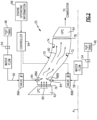
- Figure 1 schematically illustrates an example propulsion system 20 that includes an intercooling waterflow that is injected in a manner and direction that compensates for temperature, swirl, and flow distortions of a combined air and waterflow to a high pressure compressor section.
- the example propulsion system 20 is a hydrogen steam injected inter-cooled turbine engine with a core engine 22.
- the core engine 22 includes a core airflow path C through a fan 24, a compressor section 26, a combustor 28 and a turbine section 30 arranged along an engine longitudinal axis A.
- a fuel system 32 includes a hydrogen (H 2 ) fuel storage tank 34 and a fuel pump 36 to generate a fuel flow 60.
- the fan 24 drives inlet air as a core flow 38 into the compressor section 26. In the compressor section 26, the core flow 38 is compressed and communicated to the combustor 28.
- the core flow 38 is mixed with the hydrogen (H 2 ) fuel flow 60 and ignited to generate a high energy gas flow 40 that expands through the turbine section 30 where energy is extracted and utilized to drive the fan 24 and the compressor section 26.
- a bypass flow 92 may flow through the fan 24 and a bypass flow path B around the remaining components of the core engine 22.
- the high energy gas flow 40 is exhausted from the turbine section 30 and communicated through a condenser 42 and an evaporator 44.
- the condenser 42 uses bypass airflow 92 to cool a portion of the exhaust gas flow 40 to extract water 46 that is stored in a tank 48.
- a pump 50 moves water through the evaporator 44.
- heat from the exhaust gas flow 40 is used to transform at least a portion of water into a steam flow 58.
- the steam flow 58 is injected into the combustor 28 or other locations within the core flow path C.
- the example core engine 22 has an increased power output from the injected steam due to an increasing mass flow through the turbine section 30 without a corresponding increase in work from the compressor section 26.
- An example engine operation cycle may include up to (or more than) 35% steam-air-ratios (SAR) and may be assisted by a multiple fold (e.g., 2x, 3x, etc.) increase in moisture from burning H 2 as the fuel.
- SAR steam-air-ratios
- An intercooling flow of water 52 may be communicated to the compressor section 26 to reduce a temperature of the core airflow 26 and increase mass flow. Reduced temperatures and increased mass flow provided by injection of water increases compressor efficiency.
- the example compressor section 24 includes a low pressure compressor (LPC) 62 and a high pressure compressor (HPC) 64 separated by an annular passage 70.
- the turbine section 30 includes a high pressure turbine (HPT) 66, and a low pressure turbine (LPT) 68.
- the turbines 66 and 68 are coupled to a corresponding compressor section 62, 64.
- the HPT 66 is coupled to drive the HPC 64.
- the LPT 68 is coupled to drive the LPC 62 and the fan 24.
- the LPT 68 may be coupled to the fan 24 via a gearbox that is configured to reduce the speed of the shaft relative to the LPT 68 and/or the LPC 62.
- the example core engine 22 includes an intercooling pump 54 that generates a pressurized intercooling waterflow 56 that is injected into a location between the LPC 62 and the HPC 64.
- Previous compressor sections would utilize a variable inlet guide vane at the inlet to direct airflow into the HPC.
- Such inlet guide vanes are a potential source of efficiency losses because some airflow may leak past the inlet guide vane.
- Disclosed example embodiments eliminate the inlet guide vane and utilize water injection for intercooling to direct and generate desired flows into the HPC. Moreover, disclosed example embodiments vary waterflow to mitigate distortions and uneven temperature and flow distributions at various engine operating points.
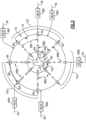
- water (depicted as waterflows 88A, 88B, and so on, and referred to herein as a waterflow 88) is injected into the passage 70 through one or more injectors 84 that are circumferentially spaced apart (best shown in Figure 3 ) about an inner radial surface 72 and an outer radial surface 74.
- the passage 70 is annular about the engine longitudinal axis A and provides for the communication of the pressurized core flow 80 from the LPC 62 to the HPC 64.
- the amount of intercooling waterflow 88 injected into the passage 70 by each of the injectors 84 is varied to control and change circumferential variations in temperature, flow and other parameters that may influence compressor operation.
- Pressurized airflow 80 through an exit 76 of the LPC 62 is communicated through the passage 70 to an inlet 78 for the HPC 64.
- the injectors 84 are circumferentially spaced apart a distance 106 about the inner radial surface 72 and a distance 98 about the outer radial surface 74.
- Each of the injectors 84 are supplied the intercooling waterflow 56 through at least one valve 86 that is controlled by a controller 94.
- a plurality of valves 86A-E are provided to supply groups of a corresponding plurality of the injectors 84.
- valves 86A-E are disclosed as controlling waterflow 56 to several of the injectors 84, other combinations and numbers of valves 86A-E could be utilized and are within the contemplation of this disclosure.
- an individual valve could be associated with each of the injectors 84 such that waterflow to each of the injectors 84 is individually controlled.
- fewer valves could be utilized to supply and control waterflow to differing groups of the injectors.
- Each of the valves 86A-E may be configured to provide proportional control of water to each corresponding injector 84.
- additional valves, conduits and fluidic storage and communication structures would be included to communicate the waterflow to each of the valves 86A-E.
- Figure 3 illustrates the injectors spaced the circumferential distance 98 apart about the outer radial surface of the passage 70.
- the example injectors 84 are illustrated as supplying different volumes of intercooling waterflow 88 in different circumferential zones 100, 102 and 104.
- the different zones 100, 102 and 104 are utilized as examples of differing distributions related to compressor flows.
- the differing distributions may include distributions in temperature, flow and/or swirl. Other flow parameters may also be considered and accommodated with varying injection of intercooling waterflow.
- a flow volume of the intercooling waterflow 88 is provided to accommodate the varying distribution.
- Figure 3 illustrates the differing waterflows 88A-E at each injector 84 by differently sized arrows.
- a first zone 100 is provided with a first intercooling waterflow schematically shown by arrow 88A that is different than a second intercooling waterflow 88B indicated by different arrows within a second zone 102.
- a third waterflow 88C within a third zone 104 is different than either of the first and second waterflows 88A and 88B.
- injectors 84 disposed about the inner radial surface 72 may provide additional variations in waterflows.
- waterflows 88D and 88E are different than other flows about the outer radial surface 74.
- the variation in each of the waterflows 88A-E is utilized to tailor the combined air and waterflow 90 ( Figure 2 ) that is eventually communicated to the HPC 64 based on a desired and/or current operating point.
- the controller 94 controls each of the valves 86A-E based on engine operation information 96.
- the engine operation information 96 includes information indicative of different operating conditions.
- the controller 94 may control the volume of water injection, based on an engine operating condition as indicated by an engine setting.
- the engine setting may be indicated by a throttle position or any other engine setting.
- the controller 94 may control the volume of water injection based on other operating conditions, parameters, such as pressure, temperature, ambient conditions, and any other condition on which engine control may be based.
- controller 94 may operate the valves 86A-E based on a feedback loop utilizing measurements indicative of compressor stability or that provides a direct measurement of a flow inlet profile to the HPC inlet 78.
- the example controller 94 is a device and system for performing necessary computing or calculation operations of the valves 86-A-E and the intercooling system 25.
- the controller 94 may be specially constructed for operation of the valves 86A-E and intercooling system 25, or it may comprise at least a general-purpose computer selectively activated or reconfigured by software instructions stored in a memory device.
- the controller 94 may further be part of full authority digital engine control (FADEC) or an electronic engine controller (EEC).
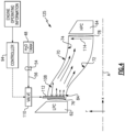
- FIG. 4 another example intercooling system 125 is schematically shown and includes injectors 84 arranged radially between the inner radial surface 72 and the outer radial surface 74 of the passage 70.
- the injectors 84 are provided an intercooling waterflow 56 through one or more valves.
- a single valve 110 is shown by way of illustrated example in Figure 4 .
- a controller 94 controls operation of the valve 110 based on a distortion profile schematically indicated by arrow 114.
- the distortion profile may consist of a temperature profile, flow profile or any other criteria indicative of flows that are controlled for communication to the HPC 64.
- the disclosed example distortion profile 114 indicates an increase in a direction from the inner radial surface 72 toward the outer radial surface 74.
- a radial distribution of water injected into the passage is indicated by arrows 108.
- the arrows increase in length toward the outer radial surface 74 to illustrate an increase in waterflow from the injectors 84 within the radial distribution profile 108.
- the distribution profile 108 may be non-uniform to correspond with different distortion profiles.
- the example distortion profile 114 indicates an increase in the radially outward direction, the distortion profile 114 may increase in a direction toward the inner radial surface 72, toward a midway point and/or in a non-uniform manner across the passage 70.
- a plurality of valves 11 0A-D provide the intercooling waterflow 56 to the injectors 84.
- the injectors 84 are supplied by a corresponding manifold 112A-D.
- the injectors 84 are shown injecting differing amounts of water depending on the radial position.
- the differing waterflows may represent different mass flow volumes of water, differing pressures and/or other variations in water injection that could be utilized to accommodate distortions within the passage 70.
- valves 110A-D a single one of the valves 110A-D is illustrated as supplying waterflow to a group of injectors distributed radially.
- multiple valves could be utilized to provide the desired radially distributed differences in the waterflow distribution 108.
- the injectors 84 may be sized differently based on a radial position to provide the desired waterflow distribution.
- the disclosed intercooling systems 25, 125 vary waterflow injection radially and circumferentially to accommodate distortions and tailor water injection to influence and control a flow profile communicated to the high pressure compressor.
Landscapes
- Engineering & Computer Science (AREA)
- Chemical & Material Sciences (AREA)
- Combustion & Propulsion (AREA)
- Mechanical Engineering (AREA)
- General Engineering & Computer Science (AREA)
- Aviation & Aerospace Engineering (AREA)
- Structures Of Non-Positive Displacement Pumps (AREA)
Abstract
Description
- The present disclosure relates generally to an intercooled turbine engine where water is injected into a compressor section.
- Reduction and/or elimination of carbon emissions generated by aircraft operation is a stated goal of aircraft manufacturers and airline operators. Gas turbine engines compress incoming core airflow, mix the compressed airflow with fuel that is ignited in a combustor to generate a high energy exhaust gas flow. Inlet guide vanes are utilized to set an angle of air flow into compressor sections. The angle of airflow may vary based on engine operating points. Gaps around movable inlet guide vanes generate secondary losses that reduce overall compressor efficiency. Moreover, an intercooling flow of water can be injected into a compressor to cool flow and improve efficiency. However, distortions within the compressor can reduce compressor efficiency and operability.
- Turbine engine manufacturers continue to seek further improvements to engine performance including improvements to reduce environmental impact while improving propulsive efficiencies.
- A propulsion system for an aircraft according to an exemplary embodiment of this invention includes, among other possible things, a core engine that includes a core flow path where air is compressed in a compressor section, communicated to a combustor section, mixed with fuel, and ignited to generate a high energy gas flow that is expanded through a turbine section. The compressor section includes a low pressure compressor that is upstream of a high pressure compressor. An intercooling system is configured to inject water into the compressor section to reduce a temperature of a core airflow within the core flow path. The intercooling system includes a plurality of injectors for injecting an intercooling waterflow into a portion of a compressor passage. The plurality of injectors are spaced apart about the compressor passage and the injection of the intercooling water flow is varied between the plurality of injectors to influence flow that is communicated to the high pressure compressor.
- In a further embodiment of the foregoing propulsion system, the volume of the intercooling waterflow is varied based on a circumferential position within the compressor passage.
- In a further embodiment of any of the foregoing propulsion systems, the volume of the intercooling waterflow is varied based on a radial position within the compressor passage.
- In a further embodiment of any of the foregoing propulsion systems, a pressure of intercooling waterflow through at least one of the plurality of injectors is different than another of the plurality of injectors.
- In a further embodiment of any of the foregoing propulsion systems, the compressor passage includes an annular passage for directing an airflow from an exit of the low pressure compressor to an inlet of the high pressure compressor. The plurality of injectors is disposed within the annular passage for generating the combined airflow and water through the annular passage to the inlet of the high pressure compressor.
- In a further embodiment of any of the foregoing propulsion systems, the plurality of injectors are spaced circumferentially apart about both an inner radial surface and an outer radial surface of the annular passage.
- In a further embodiment of any of the foregoing propulsion systems, the plurality of injectors are spaced radially apart between an inner radial surface and an outer radial surface of the annular passage.
- In a further embodiment of any of the foregoing, the propulsion system includes a controller that is programmed to control injection of the cooling waterflow through the plurality of injectors.
- In a further embodiment of any of the foregoing propulsion systems, the controller is programmed to receive information indicative of an engine operating condition and to control injection of waterflow through the plurality of injectors based on the information indicative of the engine operating condition.
- In a further embodiment of any of the foregoing propulsion systems, the controller is programmed to receive information indicative of a distortion profile within the compressor passage and to control injection of the waterflow based on the information indicative of the distortion profile.
- In a further embodiment of any of the foregoing propulsion systems, the distortion profile includes one of a temperature profile and a flow pattern profile.
- In a further embodiment of any of the foregoing propulsion systems, the controller is programed to control injection of waterflow through the plurality of injectors to generate a desired flow profile of a combined water and air flow to the high pressure compressor.
- In a further embodiment of any of the foregoing, the propulsion system further includes a condenser that is arranged along the core flow path and configured to extract water from the high energy gas flow.
- In a further embodiment of any of the foregoing propulsion systems, an evaporator is arranged along the core flow path and configured to receive a portion of the water that is extracted by the condenser to generate a steam flow. The steam flow is injected into the core flow path upstream of the turbine section.
- An intercooling system for a turbine engine according to another exemplary embodiment of this invention includes, among other possible things, a condenser that is arranged along a core flow path and configured to extract water from an exhaust gas flow, a pump where water from the condenser is pressurized, and a plurality of injectors for injecting an intercooling waterflow into a portion of a compressor passage. The plurality of injectors are spaced apart about the compressor passage and the injection of the intercooling water flow is varied between the plurality of injectors to influence flow that is communicated to a high pressure compressor.
- In a further embodiment of the foregoing intercooling system, at least one of a volume and pressure of the intercooling waterflow is varied based on a circumferential position within the compressor passage.
- In a further embodiment of any of the foregoing intercooling systems, at least one of a volume and pressure of the intercooling waterflow is varied based on a radial position within the compressor passage.
- A method of operating a compressor section of a turbine engine according to another exemplary embodiment of this invention includes, among other possible things, generating a pressurized airflow through a first compressor section, injecting a pressurized waterflow with at least one of a plurality of injectors to generate a combined pressurized air and waterflow, communicating the combined pressurized air and waterflow to a second compressor section downstream of the first compressor section, determining a distortion profile of the combined pressurized air and waterflow, and varying at least one of a volume and pressure of the intercooling waterflow between the plurality of injectors based on the determined distortion profile within a compressor passage between the first compressor section and the second compressor section.
- In a further embodiment of the foregoing, the method further includes varying at least one of a volume and pressure of the intercooling waterflow that is varied based on a circumferential position within the compressor passage.
- In a further embodiment of any of the foregoing, the method further includes varying at least one of a volume and pressure of the intercooling waterflow that is varied based on a radial position within the compressor passage.
- Although the different examples have the specific components shown in the illustrations, embodiments of this invention are not limited to those particular combinations. It is possible to use some of the components or features from one of the examples in combination with features or components from another one of the examples.
- These and other features disclosed herein can be best understood from the following specification and drawings, the following of which is a brief description.
-
-
Figure 1 is a schematic view of an example propulsion system embodiment. -
Figure 2 is a schematic view of a portion of an example intercooler system embodiment. -
Figure 3 is a schematic axial view of the example intercooler system embodiment. -
Figure 4 is schematic view of another example intercooling system embodiment. -
Figure 5 is a schematic axial view of the example intercooling system embodiment. -
Figure 1 schematically illustrates anexample propulsion system 20 that includes an intercooling waterflow that is injected in a manner and direction that compensates for temperature, swirl, and flow distortions of a combined air and waterflow to a high pressure compressor section. - The
example propulsion system 20 is a hydrogen steam injected inter-cooled turbine engine with acore engine 22. Thecore engine 22 includes a core airflow path C through afan 24, acompressor section 26, acombustor 28 and aturbine section 30 arranged along an engine longitudinal axis A. Afuel system 32 includes a hydrogen (H2)fuel storage tank 34 and afuel pump 36 to generate afuel flow 60. Thefan 24 drives inlet air as acore flow 38 into thecompressor section 26. In thecompressor section 26, thecore flow 38 is compressed and communicated to thecombustor 28. In thecombustor 28, thecore flow 38 is mixed with the hydrogen (H2)fuel flow 60 and ignited to generate a highenergy gas flow 40 that expands through theturbine section 30 where energy is extracted and utilized to drive thefan 24 and thecompressor section 26. Abypass flow 92 may flow through thefan 24 and a bypass flow path B around the remaining components of thecore engine 22. - The high
energy gas flow 40 is exhausted from theturbine section 30 and communicated through acondenser 42 and anevaporator 44. Thecondenser 42 usesbypass airflow 92 to cool a portion of theexhaust gas flow 40 to extractwater 46 that is stored in atank 48. Apump 50 moves water through theevaporator 44. In theevaporator 44, heat from theexhaust gas flow 40 is used to transform at least a portion of water into asteam flow 58. Thesteam flow 58 is injected into thecombustor 28 or other locations within the core flow path C. - The
example core engine 22 has an increased power output from the injected steam due to an increasing mass flow through theturbine section 30 without a corresponding increase in work from thecompressor section 26. An example engine operation cycle may include up to (or more than) 35% steam-air-ratios (SAR) and may be assisted by a multiple fold (e.g., 2x, 3x, etc.) increase in moisture from burning H2 as the fuel. - An intercooling flow of
water 52 may be communicated to thecompressor section 26 to reduce a temperature of thecore airflow 26 and increase mass flow. Reduced temperatures and increased mass flow provided by injection of water increases compressor efficiency. - The
example compressor section 24 includes a low pressure compressor (LPC) 62 and a high pressure compressor (HPC) 64 separated by anannular passage 70. Theturbine section 30 includes a high pressure turbine (HPT) 66, and a low pressure turbine (LPT) 68. Theturbines corresponding compressor section HPT 66 is coupled to drive theHPC 64. TheLPT 68 is coupled to drive theLPC 62 and thefan 24. In some examples, theLPT 68 may be coupled to thefan 24 via a gearbox that is configured to reduce the speed of the shaft relative to theLPT 68 and/or theLPC 62. Although theexample core engine 22 is described and shown by way of example as a two-spool engine, other engine configurations and architectures may also benefit from this disclosure and are within the contemplation and scope of this disclosure. - The
example core engine 22 includes anintercooling pump 54 that generates apressurized intercooling waterflow 56 that is injected into a location between theLPC 62 and theHPC 64. - Previous compressor sections would utilize a variable inlet guide vane at the inlet to direct airflow into the HPC. Such inlet guide vanes are a potential source of efficiency losses because some airflow may leak past the inlet guide vane. Disclosed example embodiments eliminate the inlet guide vane and utilize water injection for intercooling to direct and generate desired flows into the HPC. Moreover, disclosed example embodiments vary waterflow to mitigate distortions and uneven temperature and flow distributions at various engine operating points.
- Referring to
Figures 2 and3 , water (depicted aswaterflows passage 70 through one ormore injectors 84 that are circumferentially spaced apart (best shown inFigure 3 ) about an innerradial surface 72 and an outerradial surface 74. Thepassage 70 is annular about the engine longitudinal axis A and provides for the communication of thepressurized core flow 80 from theLPC 62 to theHPC 64. The amount of intercooling waterflow 88 injected into thepassage 70 by each of theinjectors 84 is varied to control and change circumferential variations in temperature, flow and other parameters that may influence compressor operation. -
Pressurized airflow 80 through anexit 76 of theLPC 62 is communicated through thepassage 70 to aninlet 78 for theHPC 64. Theinjectors 84 are circumferentially spaced apart adistance 106 about the innerradial surface 72 and adistance 98 about the outerradial surface 74. Each of theinjectors 84 are supplied the intercooling waterflow 56 through at least one valve 86 that is controlled by acontroller 94. In one example embodiment, a plurality ofvalves 86A-E are provided to supply groups of a corresponding plurality of theinjectors 84. - Although the
example valves 86A-E are disclosed as controllingwaterflow 56 to several of theinjectors 84, other combinations and numbers ofvalves 86A-E could be utilized and are within the contemplation of this disclosure. For example, an individual valve could be associated with each of theinjectors 84 such that waterflow to each of theinjectors 84 is individually controlled. Alternatively, fewer valves could be utilized to supply and control waterflow to differing groups of the injectors. Each of thevalves 86A-E may be configured to provide proportional control of water to eachcorresponding injector 84. Moreover, additional valves, conduits and fluidic storage and communication structures would be included to communicate the waterflow to each of thevalves 86A-E. -
Figure 3 illustrates the injectors spaced thecircumferential distance 98 apart about the outer radial surface of thepassage 70. The example injectors 84 are illustrated as supplying different volumes of intercooling waterflow 88 in differentcircumferential zones different zones -
Figure 3 illustrates the differing waterflows 88A-E at eachinjector 84 by differently sized arrows. In one example embodiment, afirst zone 100 is provided with a first intercooling waterflow schematically shown byarrow 88A that is different than asecond intercooling waterflow 88B indicated by different arrows within asecond zone 102. Athird waterflow 88C within athird zone 104 is different than either of the first andsecond waterflows - Additionally,
injectors 84 disposed about the innerradial surface 72 may provide additional variations in waterflows. In the illustrated example embodiment,waterflows radial surface 74. The variation in each of thewaterflows 88A-E is utilized to tailor the combined air and waterflow 90 (Figure 2 ) that is eventually communicated to theHPC 64 based on a desired and/or current operating point. - The
controller 94 controls each of thevalves 86A-E based onengine operation information 96. Theengine operation information 96 includes information indicative of different operating conditions. For example, thecontroller 94 may control the volume of water injection, based on an engine operating condition as indicated by an engine setting. The engine setting may be indicated by a throttle position or any other engine setting. Moreover, thecontroller 94 may control the volume of water injection based on other operating conditions, parameters, such as pressure, temperature, ambient conditions, and any other condition on which engine control may be based. - Alternatively, the
controller 94 may operate thevalves 86A-E based on a feedback loop utilizing measurements indicative of compressor stability or that provides a direct measurement of a flow inlet profile to theHPC inlet 78. - The
example controller 94 is a device and system for performing necessary computing or calculation operations of the valves 86-A-E and theintercooling system 25. Thecontroller 94 may be specially constructed for operation of thevalves 86A-E andintercooling system 25, or it may comprise at least a general-purpose computer selectively activated or reconfigured by software instructions stored in a memory device. Thecontroller 94 may further be part of full authority digital engine control (FADEC) or an electronic engine controller (EEC). - Referring to
Figures 4 and5 , anotherexample intercooling system 125 is schematically shown and includesinjectors 84 arranged radially between the innerradial surface 72 and the outerradial surface 74 of thepassage 70. Theinjectors 84 are provided anintercooling waterflow 56 through one or more valves. Asingle valve 110 is shown by way of illustrated example inFigure 4 . Acontroller 94 controls operation of thevalve 110 based on a distortion profile schematically indicated byarrow 114. The distortion profile may consist of a temperature profile, flow profile or any other criteria indicative of flows that are controlled for communication to theHPC 64. The disclosedexample distortion profile 114 indicates an increase in a direction from the innerradial surface 72 toward the outerradial surface 74. A radial distribution of water injected into the passage is indicated byarrows 108. The arrows increase in length toward the outerradial surface 74 to illustrate an increase in waterflow from theinjectors 84 within theradial distribution profile 108. - Although a uniform increase in
waterflow distribution profile 108 is shown by way of example, thedistribution profile 108 may be non-uniform to correspond with different distortion profiles. Moreover, although theexample distortion profile 114 indicates an increase in the radially outward direction, thedistortion profile 114 may increase in a direction toward the innerradial surface 72, toward a midway point and/or in a non-uniform manner across thepassage 70. - As is best shown in
Figure 5 , a plurality of valves 11 0A-D provide the intercooling waterflow 56 to theinjectors 84. In one disclosed embodiment, theinjectors 84 are supplied by a corresponding manifold 112A-D. Theinjectors 84 are shown injecting differing amounts of water depending on the radial position. The differing waterflows may represent different mass flow volumes of water, differing pressures and/or other variations in water injection that could be utilized to accommodate distortions within thepassage 70. - In the illustrated example, a single one of the
valves 110A-D is illustrated as supplying waterflow to a group of injectors distributed radially. However, it is within the contemplation of this disclosure that multiple valves could be utilized to provide the desired radially distributed differences in thewaterflow distribution 108. Moreover, theinjectors 84 may be sized differently based on a radial position to provide the desired waterflow distribution. - Accordingly, the disclosed
intercooling systems - Although an example engine configuration is described by way of example, it will be appreciated that other engine configurations may include additional structures and features and are within the contemplation and scope of this disclosure.
- Although an example embodiment has been disclosed, a worker of ordinary skill in this art would recognize that certain modifications would come within the scope of this disclosure. For that reason, the following claims should be studied to determine the scope and content of this disclosure.
Claims (15)
- A propulsion system for an aircraft comprising:a core engine (22) including a core flow path (C) where air is compressed in a compressor section (26), communicated to a combustor section, mixed with fuel, and ignited to generate a high energy gas flow that is expanded through a turbine section (30), wherein the compressor section (26) includes a low pressure compressor (62) upstream of a high pressure compressor (64); andan intercooling system (25; 125) configured to inject water into the compressor section (26) to reduce a temperature of a core airflow within the core flow path (C), the intercooling system (25; 125) including a plurality of injectors (84) for injecting an intercooling waterflow into a portion of a compressor passage, wherein the plurality of injectors (84) are spaced apart about the compressor passage and the injection of the intercooling water flow is varied between the plurality of injectors (84) to influence flow communicated to the high pressure compressor (64).
- The propulsion system as recited in claim 1, wherein the volume of the intercooling waterflow is varied based on a circumferential position within the compressor passage.
- The propulsion system as recited in claim 1 or 2, wherein the volume of the intercooling waterflow is varied based on a radial position within the compressor passage.
- The propulsion system as recited in any preceding claim, wherein a pressure of intercooling waterflow through at least one of the plurality of injectors (84) is different than another of the plurality of injectors (84).
- The propulsion system as recited in any preceding claim, wherein the compressor passage comprises an annular passage (70) for directing an airflow from an exit of the low pressure compressor (62) to an inlet (78) of the high pressure compressor (64), wherein the plurality of injectors (84) is disposed within the annular passage (70) for generating the combined airflow and water through the annular passage (70) to the inlet (78) of the high pressure compressor (64).
- The propulsion system as recited in claim 5, wherein the plurality of injectors (84) are spaced circumferentially apart about both an inner radial surface (72) and an outer radial surface (74) of the annular passage (70).
- The propulsion system as recited in claim 5 or 6, wherein the plurality of injectors (84) are spaced radially apart between an or the inner radial surface (72) and an or the outer radial surface (74) of the annular passage (70).
- The propulsion system as recited in any preceding claim, including a controller (94) programmed to control injection of the cooling waterflow through the plurality of injectors (84).
- The propulsion system as recited in claim 8, wherein:the controller (94) is programmed to receive information indicative of an engine operating condition and to control injection of waterflow through the plurality of injectors (84) based on the information indicative of the engine operating condition; and/orwherein the controller (94) is programed to control injection of waterflow through the plurality of injectors (84) to generate a desired flow profile of a combined water and air flow to the high pressure compressor (64).
- The propulsion system as recited in claim 8 or 9, wherein the controller (94) is programmed to receive information indicative of a distortion profile (114) within the compressor passage and to control injection of the waterflow based on the information indicative of the distortion profile (114), optionally wherein the distortion profile (114) comprises one of a temperature profile and a flow pattern profile.
- The propulsion system as recited in any preceding claim, further comprising a condenser (42) arranged along the core flow path (C) and configured to extract water from the high energy gas flow, optionally wherein an evaporator (44) is arranged along the core flow path (C) and configured to receive a portion of the water extracted by the condenser (42) to generate a steam flow (58), wherein the steam flow (58) is injected into the core flow path (C) upstream of the turbine section (30).
- An intercooling system for a turbine engine comprising:a condenser (42) arranged along a core flow path (C) and configured to extract water from an exhaust gas flow (40);a pump (50) where water from the condenser (42) is pressurized; anda plurality of injectors (84) for injecting an intercooling waterflow into a portion of a compressor passage, wherein the plurality of injectors (84) are spaced apart about the compressor passage and the injection of the intercooling water flow is varied between the plurality of injectors (84) to influence flow communicated to a high pressure compressor (64), optionally wherein:at least one of a volume and pressure of the intercooling waterflow is varied based on a circumferential position within the compressor passage; and/orat least one of a volume and pressure of the intercooling waterflow is varied based on a radial position within the compressor passage.
- A method of operating a compressor section of a turbine engine comprising:generating a pressurized airflow through a first compressor section (62);injecting a pressurized waterflow with at least one of a plurality of injectors (84) to generate a combined pressurized air and waterflow;communicating the combined pressurized air and waterflow to a second compressor section (64) downstream of the first compressor section (62);determining a distortion profile (114) of the combined pressurized air and waterflow; andvarying at least one of a volume and pressure of the intercooling waterflow between the plurality of injectors (84) based on the determined distortion profile (114) within a compressor passage between the first compressor section (62) and the second compressor section (64).
- The method as recited in claim 13, further comprising varying at least one of a volume and pressure of the intercooling waterflow based on a circumferential position within the compressor passage.
- The method as recited in claim 13 or 14, further comprising varying at least one of a volume and pressure of the intercooling waterflow based on a radial position within the compressor passage.
Applications Claiming Priority (1)
| Application Number | Priority Date | Filing Date | Title |
|---|---|---|---|
| US18/512,433 US12134984B1 (en) | 2023-11-17 | 2023-11-17 | Fluidic compressor inlet guide vanes |
Publications (2)
| Publication Number | Publication Date |
|---|---|
| EP4556697A2 true EP4556697A2 (en) | 2025-05-21 |
| EP4556697A3 EP4556697A3 (en) | 2025-08-13 |
Family
ID=93294537
Family Applications (1)
| Application Number | Title | Priority Date | Filing Date |
|---|---|---|---|
| EP24213392.4A Pending EP4556697A3 (en) | 2023-11-17 | 2024-11-15 | Fluidic compressor inlet guide vanes |
Country Status (2)
| Country | Link |
|---|---|
| US (1) | US12134984B1 (en) |
| EP (1) | EP4556697A3 (en) |
Families Citing this family (1)
| Publication number | Priority date | Publication date | Assignee | Title |
|---|---|---|---|---|
| US20250369393A1 (en) * | 2024-05-30 | 2025-12-04 | Rtx Corporation | Axial flow angled condenser arrangement for an aircraft propulsion system |
Family Cites Families (13)
| Publication number | Priority date | Publication date | Assignee | Title |
|---|---|---|---|---|
| US3100964A (en) | 1959-11-25 | 1963-08-20 | Gen Motors Corp | Water injection system for a multistage compressor |
| US4569195A (en) | 1984-04-27 | 1986-02-11 | General Electric Company | Fluid injection gas turbine engine and method for operating |
| US6467252B1 (en) * | 1998-07-24 | 2002-10-22 | General Electric Company | Nozzles for water injection in a turbine engine |
| GB2365074B (en) | 1999-07-13 | 2003-08-13 | Allison Advanced Dev Co | Gas turbine engine power boost using micro droplet liquid injection |
| US6722136B2 (en) * | 2002-01-30 | 2004-04-20 | The Boeing Company | Aircraft engine water misting inter-cooler |
| DE10256193A1 (en) * | 2002-12-02 | 2004-06-09 | Alstom Technology Ltd | Method for controlling the liquid injection into an inflow channel of an engine or machine |
| US8291714B2 (en) * | 2007-12-06 | 2012-10-23 | Rolls-Royce Power Endgineering PLC | Radial staging method and configuration of a liquid injection system for power plants |
| DE102011107523B4 (en) | 2011-07-15 | 2016-08-11 | MTU Aero Engines AG | System for injecting a fluid, compressor and turbomachine |
| US10677164B2 (en) * | 2016-11-15 | 2020-06-09 | General Electric Company | Cooling system for a turbine engine |
| FR3073002B1 (en) | 2017-10-26 | 2020-11-06 | Safran Helicopter Engines | GUIDE VANE WITH COOLANT INJECTION CIRCUIT |
| FR3110937B1 (en) * | 2020-05-28 | 2022-04-29 | Safran | Installation for supplying cryogenic fuel to the combustion chamber of a turbomachine. |
| US11753993B1 (en) * | 2022-02-11 | 2023-09-12 | Raytheon Technologies Corporation | Turbine engine with mass rejection |
| US12163467B2 (en) * | 2022-05-13 | 2024-12-10 | Rtx Corporation | Condenser for hydrogen steam injected turbine engine |
-
2023
- 2023-11-17 US US18/512,433 patent/US12134984B1/en active Active
-
2024
- 2024-11-15 EP EP24213392.4A patent/EP4556697A3/en active Pending
Also Published As
| Publication number | Publication date |
|---|---|
| EP4556697A3 (en) | 2025-08-13 |
| US12134984B1 (en) | 2024-11-05 |
Similar Documents
| Publication | Publication Date | Title |
|---|---|---|
| US6550235B2 (en) | Combined cycle pulse detonation turbine engine operating method | |
| US10443501B2 (en) | Turbocooled vane of a gas turbine engine | |
| US20200393128A1 (en) | Variable geometry rotating detonation combustor | |
| US7631484B2 (en) | High pressure ratio aft fan | |
| US11255544B2 (en) | Rotating detonation combustion and heat exchanger system | |
| US6889505B2 (en) | Pulse detonation system for a gas turbine engine | |
| EP3933268B1 (en) | Assembly for a turbomachine comprising a combustor, an outer casing and a high pressure plenum | |
| US20160273396A1 (en) | Power generation system having compressor creating excess air flow and heat exchanger therefor | |
| US12215634B1 (en) | Turbine engine including a steam system | |
| EP3922834B1 (en) | Systems and methods for determination of gas turbine fuel split for head end temperature control | |
| US20160273397A1 (en) | Power generation system having compressor creating excess air flow and supplemental compressor therefor | |
| EP4556697A2 (en) | Fluidic compressor inlet guide vanes | |
| EP3070300B1 (en) | Power generation system having compressor creating excess air flow and cooling fluid injection therefor | |
| US11702981B1 (en) | Turbine engine bleed waste heat recovery | |
| CN113123878A (en) | Variable area metering of different alpha | |
| CN112555056A (en) | Afterburning circulating liquid engine core system thermal test device and parameter coordination method | |
| EP4556700A2 (en) | Fluidic compressor inlet guide vane | |
| US20190360695A1 (en) | Rotating Detonation Combustion System | |
| EP3483418B1 (en) | Intercooled cooled cooling integrated air cycle machine | |
| EP4502342A1 (en) | Steam heated flange for thermal gradient control | |
| US10358979B2 (en) | Turbocooled vane of a gas turbine engine | |
| US12320293B1 (en) | Turbine engine including a steam system | |
| US20250163850A1 (en) | Turbine engine including a steam system | |
| US20250223920A1 (en) | Exhaust system for a gas turbine engine, gas turbine engine having the same, and methods of manufacturing, configuring, and using the same | |
| EP4545771A1 (en) | Turbine engine including a fuel and steam system |
Legal Events
| Date | Code | Title | Description |
|---|---|---|---|
| PUAI | Public reference made under article 153(3) epc to a published international application that has entered the european phase |
Free format text: ORIGINAL CODE: 0009012 |
|
| STAA | Information on the status of an ep patent application or granted ep patent |
Free format text: STATUS: THE APPLICATION HAS BEEN PUBLISHED |
|
| AK | Designated contracting states |
Kind code of ref document: A2 Designated state(s): AL AT BE BG CH CY CZ DE DK EE ES FI FR GB GR HR HU IE IS IT LI LT LU LV MC ME MK MT NL NO PL PT RO RS SE SI SK SM TR |
|
| PUAL | Search report despatched |
Free format text: ORIGINAL CODE: 0009013 |
|
| AK | Designated contracting states |
Kind code of ref document: A3 Designated state(s): AL AT BE BG CH CY CZ DE DK EE ES FI FR GB GR HR HU IE IS IT LI LT LU LV MC ME MK MT NL NO PL PT RO RS SE SI SK SM TR |
|
| RIC1 | Information provided on ipc code assigned before grant |
Ipc: F02C 3/22 20060101AFI20250710BHEP Ipc: F02C 7/143 20060101ALI20250710BHEP |
|
| STAA | Information on the status of an ep patent application or granted ep patent |
Free format text: STATUS: REQUEST FOR EXAMINATION WAS MADE |
|
| 17P | Request for examination filed |
Effective date: 20260204 |