EP4556651A1 - Air pump with automatic air pumping function - Google Patents
Air pump with automatic air pumping function Download PDFInfo
- Publication number
- EP4556651A1 EP4556651A1 EP24154098.8A EP24154098A EP4556651A1 EP 4556651 A1 EP4556651 A1 EP 4556651A1 EP 24154098 A EP24154098 A EP 24154098A EP 4556651 A1 EP4556651 A1 EP 4556651A1
- Authority
- EP
- European Patent Office
- Prior art keywords
- air
- shell
- pump
- automatic air
- pumping function
- Prior art date
- Legal status (The legal status is an assumption and is not a legal conclusion. Google has not performed a legal analysis and makes no representation as to the accuracy of the status listed.)
- Granted
Links
Images




Classifications
-
- B—PERFORMING OPERATIONS; TRANSPORTING
- B25—HAND TOOLS; PORTABLE POWER-DRIVEN TOOLS; MANIPULATORS
- B25B—TOOLS OR BENCH DEVICES NOT OTHERWISE PROVIDED FOR, FOR FASTENING, CONNECTING, DISENGAGING, OR HOLDING
- B25B11/00—Work holders not covered by any preceding group in the subclass, e.g. magnetic work holders, vacuum work holders
- B25B11/005—Vacuum work holders
- B25B11/007—Vacuum work holders portable, e.g. handheld
-
- F—MECHANICAL ENGINEERING; LIGHTING; HEATING; WEAPONS; BLASTING
- F04—POSITIVE - DISPLACEMENT MACHINES FOR LIQUIDS; PUMPS FOR LIQUIDS OR ELASTIC FLUIDS
- F04B—POSITIVE-DISPLACEMENT MACHINES FOR LIQUIDS; PUMPS
- F04B35/00—Piston pumps specially adapted for elastic fluids and characterised by the driving means to their working members, or by combination with, or adaptation to, specific driving engines or motors, not otherwise provided for
- F04B35/04—Piston pumps specially adapted for elastic fluids and characterised by the driving means to their working members, or by combination with, or adaptation to, specific driving engines or motors, not otherwise provided for the means being electric
-
- F—MECHANICAL ENGINEERING; LIGHTING; HEATING; WEAPONS; BLASTING
- F04—POSITIVE - DISPLACEMENT MACHINES FOR LIQUIDS; PUMPS FOR LIQUIDS OR ELASTIC FLUIDS
- F04B—POSITIVE-DISPLACEMENT MACHINES FOR LIQUIDS; PUMPS
- F04B35/00—Piston pumps specially adapted for elastic fluids and characterised by the driving means to their working members, or by combination with, or adaptation to, specific driving engines or motors, not otherwise provided for
- F04B35/06—Mobile combinations
-
- F—MECHANICAL ENGINEERING; LIGHTING; HEATING; WEAPONS; BLASTING
- F04—POSITIVE - DISPLACEMENT MACHINES FOR LIQUIDS; PUMPS FOR LIQUIDS OR ELASTIC FLUIDS
- F04B—POSITIVE-DISPLACEMENT MACHINES FOR LIQUIDS; PUMPS
- F04B39/00—Component parts, details, or accessories, of pumps or pumping systems specially adapted for elastic fluids, not otherwise provided for in, or of interest apart from, groups F04B25/00 - F04B37/00
- F04B39/12—Casings; Cylinders; Cylinder heads; Fluid connections
-
- F—MECHANICAL ENGINEERING; LIGHTING; HEATING; WEAPONS; BLASTING
- F04—POSITIVE - DISPLACEMENT MACHINES FOR LIQUIDS; PUMPS FOR LIQUIDS OR ELASTIC FLUIDS
- F04B—POSITIVE-DISPLACEMENT MACHINES FOR LIQUIDS; PUMPS
- F04B39/00—Component parts, details, or accessories, of pumps or pumping systems specially adapted for elastic fluids, not otherwise provided for in, or of interest apart from, groups F04B25/00 - F04B37/00
- F04B39/12—Casings; Cylinders; Cylinder heads; Fluid connections
- F04B39/121—Casings
-
- F—MECHANICAL ENGINEERING; LIGHTING; HEATING; WEAPONS; BLASTING
- F04—POSITIVE - DISPLACEMENT MACHINES FOR LIQUIDS; PUMPS FOR LIQUIDS OR ELASTIC FLUIDS
- F04B—POSITIVE-DISPLACEMENT MACHINES FOR LIQUIDS; PUMPS
- F04B39/00—Component parts, details, or accessories, of pumps or pumping systems specially adapted for elastic fluids, not otherwise provided for in, or of interest apart from, groups F04B25/00 - F04B37/00
- F04B39/12—Casings; Cylinders; Cylinder heads; Fluid connections
- F04B39/123—Fluid connections
-
- F—MECHANICAL ENGINEERING; LIGHTING; HEATING; WEAPONS; BLASTING
- F04—POSITIVE - DISPLACEMENT MACHINES FOR LIQUIDS; PUMPS FOR LIQUIDS OR ELASTIC FLUIDS
- F04B—POSITIVE-DISPLACEMENT MACHINES FOR LIQUIDS; PUMPS
- F04B49/00—Control, e.g. of pump delivery, or pump pressure of, or safety measures for, machines, pumps, or pumping installations, not otherwise provided for, or of interest apart from, groups F04B1/00 - F04B47/00
-
- F—MECHANICAL ENGINEERING; LIGHTING; HEATING; WEAPONS; BLASTING
- F04—POSITIVE - DISPLACEMENT MACHINES FOR LIQUIDS; PUMPS FOR LIQUIDS OR ELASTIC FLUIDS
- F04B—POSITIVE-DISPLACEMENT MACHINES FOR LIQUIDS; PUMPS
- F04B49/00—Control, e.g. of pump delivery, or pump pressure of, or safety measures for, machines, pumps, or pumping installations, not otherwise provided for, or of interest apart from, groups F04B1/00 - F04B47/00
- F04B49/02—Stopping, starting, unloading or idling control
- F04B49/022—Stopping, starting, unloading or idling control by means of pressure
-
- F—MECHANICAL ENGINEERING; LIGHTING; HEATING; WEAPONS; BLASTING
- F04—POSITIVE - DISPLACEMENT MACHINES FOR LIQUIDS; PUMPS FOR LIQUIDS OR ELASTIC FLUIDS
- F04B—POSITIVE-DISPLACEMENT MACHINES FOR LIQUIDS; PUMPS
- F04B49/00—Control, e.g. of pump delivery, or pump pressure of, or safety measures for, machines, pumps, or pumping installations, not otherwise provided for, or of interest apart from, groups F04B1/00 - F04B47/00
- F04B49/06—Control using electricity
-
- F—MECHANICAL ENGINEERING; LIGHTING; HEATING; WEAPONS; BLASTING
- F04—POSITIVE - DISPLACEMENT MACHINES FOR LIQUIDS; PUMPS FOR LIQUIDS OR ELASTIC FLUIDS
- F04B—POSITIVE-DISPLACEMENT MACHINES FOR LIQUIDS; PUMPS
- F04B49/00—Control, e.g. of pump delivery, or pump pressure of, or safety measures for, machines, pumps, or pumping installations, not otherwise provided for, or of interest apart from, groups F04B1/00 - F04B47/00
- F04B49/06—Control using electricity
- F04B49/065—Control using electricity and making use of computers
-
- F—MECHANICAL ENGINEERING; LIGHTING; HEATING; WEAPONS; BLASTING
- F04—POSITIVE - DISPLACEMENT MACHINES FOR LIQUIDS; PUMPS FOR LIQUIDS OR ELASTIC FLUIDS
- F04B—POSITIVE-DISPLACEMENT MACHINES FOR LIQUIDS; PUMPS
- F04B49/00—Control, e.g. of pump delivery, or pump pressure of, or safety measures for, machines, pumps, or pumping installations, not otherwise provided for, or of interest apart from, groups F04B1/00 - F04B47/00
- F04B49/08—Regulating by delivery pressure
-
- E—FIXED CONSTRUCTIONS
- E04—BUILDING
- E04F—FINISHING WORK ON BUILDINGS, e.g. STAIRS, FLOORS
- E04F21/00—Implements for finishing work on buildings
- E04F21/18—Implements for finishing work on buildings for setting wall or ceiling slabs or plates
- E04F21/1838—Implements for finishing work on buildings for setting wall or ceiling slabs or plates for setting a plurality of similar elements
- E04F21/1883—Implements for finishing work on buildings for setting wall or ceiling slabs or plates for setting a plurality of similar elements by simultaneously applying several elements, e.g. templates
- E04F21/1888—Implements for finishing work on buildings for setting wall or ceiling slabs or plates for setting a plurality of similar elements by simultaneously applying several elements, e.g. templates using suction-cups
-
- F—MECHANICAL ENGINEERING; LIGHTING; HEATING; WEAPONS; BLASTING
- F04—POSITIVE - DISPLACEMENT MACHINES FOR LIQUIDS; PUMPS FOR LIQUIDS OR ELASTIC FLUIDS
- F04B—POSITIVE-DISPLACEMENT MACHINES FOR LIQUIDS; PUMPS
- F04B2205/00—Fluid parameters
- F04B2205/03—Pressure in the compression chamber
-
- F—MECHANICAL ENGINEERING; LIGHTING; HEATING; WEAPONS; BLASTING
- F04—POSITIVE - DISPLACEMENT MACHINES FOR LIQUIDS; PUMPS FOR LIQUIDS OR ELASTIC FLUIDS
- F04B—POSITIVE-DISPLACEMENT MACHINES FOR LIQUIDS; PUMPS
- F04B2205/00—Fluid parameters
- F04B2205/04—Pressure in the outlet chamber
-
- F—MECHANICAL ENGINEERING; LIGHTING; HEATING; WEAPONS; BLASTING
- F04—POSITIVE - DISPLACEMENT MACHINES FOR LIQUIDS; PUMPS FOR LIQUIDS OR ELASTIC FLUIDS
- F04B—POSITIVE-DISPLACEMENT MACHINES FOR LIQUIDS; PUMPS
- F04B2205/00—Fluid parameters
- F04B2205/05—Pressure after the pump outlet
Definitions
- the present disclosure relates to the technical field of air pumps on vacuum suction cups, and in particular, to an air pump with an automatic pumping function.
- An air pump is commonly used pump equipment, which is mainly configured to pump air and achieves a negative pressure or a positive pressure by increasing or decreasing a volume.
- the air pump is used in many products, such as a clothing storage and a vacuum suction cup.
- the air pump is used in the vacuum suction cup more frequently. Workers need to transport tiles during house decoration nowadays. Therefore, it is a common way to combine an air pump with a vacuum suction cup to transport tiles, which can achieve safe and efficient transferring of tiles, and can also assist the workers in tile laying according to the principle of the air pump.
- the air pump needs to be used to pump out air of a vacuum suction cup and tile contact surface to form a negative pressure inside, so that a worker can lift up the tile.
- external air easily enters from a space between the vacuum suction cup and the tile.
- the air pump on the existing vacuum suction cup cannot automatically perform an air pumping operation when an air pressure value changes, which easily causes unfirmness between the tile and the vacuum suction cup and even causes the tile to fall off.
- the present disclosure aims to provide an air pump with an automatic air pumping function to solve the problems described above, which improves the following problems:
- An air pump on an existing vacuum suction cup cannot automatically perform an air pumping operation when an air pressure value changes, which easily causes unfirmness between a tile and the vacuum suction cup and even causes the tile to fall off.
- An air pump with an automatic air pumping function includes a shell and a sealing ring, wherein an automatic air replenishing mechanism is arranged at one end of the shell, and the other end of the shell is sleeved with a mounting barrel.
- the automatic air replenishing mechanism includes a battery mounting box mounted on an inner wall of the shell; a battery pack is arranged inside the battery mounting box; a vacuum pump is arranged on the inner wall of the shell; one end of the shell is clamped with a detection box; an air pressure sensor is arranged inside the detection box; a two-way valve communicated with the vacuum pump is embedded into the other end of the detection box; the sealing ring sleeves a surface of the detection box; a shape of the sealing ring is a hollow circular truncated cone; a digital display circuit board is arranged on a surface of the battery mounting box; and an output end of the battery pack is electrically connected to an input end of the digital display circuit board.
- the automatic air replenishing mechanism in the device can use the air pressure sensor to automatically detect an air pressure in an inner cavity of a suction cup; when an air pressure value changes, the intensity of a negative pressure will change; the vacuum pump automatically runs to pump air from the device; and meanwhile, the air pressure sensor can make air pumping more intelligent, and the process runs automatically during the use of the device without manual control, so that tiles will not be separated from the vacuum suction cup during transferring or laying.
- the automatic air replenishing mechanism further includes a digital display board arranged on a surface of the mounting barrel; the digital display board and the digital display circuit board are electrically connected in both directions; the other end of the mounting barrel is provided with a switch; and the switch is electrically connected to the battery pack.
- the digital display board can display values such as the air pressure value, and an operator can also view states more intuitively. This makes the device more convenient to use.
- the user can use a manual air pumping function.
- an O-ring is arranged on a surface of an end portion of the two-way valve; an outer wall of the O-ring is in close contact with the detection box; and the O-ring is a rubber material member.
- the O-ring can improve the sealing performance between the two-way valve and the detection box, reduce air leakage of the device, and also adjust the air pressure value more stably.
- a hose is arranged between the two-way valve and the vacuum pump, and an end portion of the hose penetrates through the detection box.
- the hose can be disassembled and removed according to a situation, so that the device is more convenient to disassemble.
- the inner wall of the shell is fixedly connected with two mounting blocks; and two L-shaped mounting slots matched with the mounting blocks are formed in the surface of the detection box.
- the mounting blocks are first placed at notches of the L-shaped mounting slots. After movement for a period of time, the detection box is rotated to achieve the mounting operation, making mounting and removal more convenient.
- the inner wall of the shell is provided with a connecting plate; and the connecting plate is connected to one end of the vacuum pump.
- the connecting plate can be used to limit the vacuum pump, so that the vacuum pump is more stable in the shell.
- a round hole is formed in a middle position of the other end of the mounting barrel, and a size of the round hole is matched with a size of the switch.
- the air pressure sensor is electrically connected to the digital display circuit board; and a sensing range of the air pressure sensor is from 0 kPa to 90 kPa at a negative pressure.
- 1 shell; 101: mounting block; 102: connecting plate; 2: sealing ring; 3: automatic air replenishing mechanism; 301: battery mounting box; 302: battery pack; 303: vacuum pump; 304: detection box; 305: air pressure sensor; 306: two-way valve; 307: digital display circuit board; 308: digital display board; 309: switch; 310: O-ring; 311: hose; 312: mounting slot; 4: mounting barrel; and 401: round hole.
- an air pump with an automatic air pumping function includes a shell 1 and a sealing ring 2; an automatic air replenishing mechanism 3 is arranged at one end of the shell 1; a mounting barrel 4 sleeves the other end of the shell 1; the automatic air replenishing mechanism 3 includes a battery mounting box 301 mounted on an inner wall of the shell 1; a battery pack 302 is arranged inside the battery mounting box 301; a vacuum pump 303 is arranged on the inner wall of the shell 1; one end of the shell 1 is clamped with a detection box 304; an air pressure sensor 305 is arranged inside the detection box 304; a two-way valve 306 communicated with the vacuum pump 303 is embedded into the other end of the detection box 304; the sealing ring 2 sleeves a surface of the detection box 304; a shape of the sealing ring 2 is a hollow circular truncated cone; a digital display circuit board 307 is arranged on a surface of the battery mounting box 301;
- the vacuum suction cup and the air pump are first mounted using the sealing ring 2.
- the device is first used to make the vacuum suction cup in a set negative pressure state.
- the air pressure sensor 305 can monitor an air pressure in real time. If an air pressure value is less than a preset value, the air pressure sensor 305 may transmit a signal to the digital display circuit board 307.
- the digital display circuit board 307 transmits the signal to the vacuum pump 303, and the battery pack 302 provides a driving force for the vacuum pump 303.
- the two-way valve 306 is used for air pumping, so that an internal pressure reaches a preliminary preset value, and a negative pressure state is achieved.
- the automatic air replenishing mechanism 3 in the device can use the air pressure sensor 305 to automatically detect an air pressure in an inner cavity of the suction cup; when the air pressure value changes, the intensity of the negative pressure will change; the vacuum pump 303 automatically runs to pump air from the device; and meanwhile, the air pressure sensor 305 can make air pumping more intelligent, and the process runs automatically during the use of the device without manual control, so that tiles will not be separated from the vacuum suction cup during transportation or laying.
- the automatic air replenishing mechanism 3 further includes a digital display board 308 arranged on a surface of the mounting barrel 4; the digital display board 308 and the digital display circuit board 307 are electrically connected in both directions; the other end of the mounting barrel 4 is provided with a switch 309; and the switch 309 is electrically connected to the battery pack 302.
- the digital display board 308 can display values such as the air pressure value, and an operator can also view states more intuitively. This makes the device more convenient to use.
- An O-ring 310 is arranged on a surface of an end portion of the two-way valve 306; an outer wall of the O-ring 310 is in close contact with the detection box 304; and the O-ring 310 is a rubber material member.
- a hose 311 is arranged between the two-way valve 306 and the vacuum pump 303, and an end portion of the hose 311 penetrates through the detection box 304.
- the hose 311 can be disassembled and removed according to a situation, so that the device is more convenient to disassemble.
- the inner wall of the shell 1 is fixedly connected with two mounting blocks 101; and two L-shaped mounting slots 312 matched with the mounting blocks 101 are formed in the surface of the detection box 304.
- the mounting blocks 101 are first placed at notches of the L-shaped mounting slots 312. After movement for a period of time, the detection box 304 is rotated to achieve the mounting operation, making mounting and removal more convenient.
- a negative pressure value of the air pressure sensor 305 is between 500 MMhg and 200 MMhg.
- the inner wall of the shell 1 is provided with a connecting plate 102; and the connecting plate 102 is connected to one end of the vacuum pump 303.
- a round hole 401 is formed in a middle position of the other end of the mounting barrel 4, and a size of the round hole 401 is matched with a size of the switch 309.
- the air pressure sensor 305 is electrically connected to the digital display circuit board 307; and a sensing range of the air pressure sensor 305 is from 0 kPa to 90 kPa at a negative pressure.
- the vacuum suction cup and the air pump are first mounted using the sealing ring 2.
- the device is first used to make the vacuum suction cup in a set negative pressure state.
- the air pressure sensor 305 can monitor an air pressure in real time. If an air pressure value is less than a preset value, the air pressure sensor 305 may transmit a signal to the digital display circuit board 307.
- the digital display circuit board 307 transmits the signal to the vacuum pump 303, and the battery pack 302 provides a driving force for the vacuum pump 303.
- the two-way valve 306 is used for air pumping, so that an internal pressure reaches a preliminary preset value, and a negative pressure state is achieved.
- the digital display board 308 can display values such as the air pressure value, and an operator can also view states more intuitively. This makes the device more convenient to use.
- the battery pack, the vacuum pump, the air pressure sensor, the two-way valve, the digital display circuit board, and the digital display board mentioned in the above descriptions are all mature devices applied in the prior art. Specific models can be selected according to actual needs.
- the battery pack, the vacuum pump, the air pressure sensor, the two-way valve, the digital display circuit board, and the digital display board can be powered by a built-in power source or a mains supply. A specific power supplying way depends on a situation, and will not be elaborate here.
Landscapes
- Engineering & Computer Science (AREA)
- Mechanical Engineering (AREA)
- General Engineering & Computer Science (AREA)
- Computer Hardware Design (AREA)
- Compressors, Vaccum Pumps And Other Relevant Systems (AREA)
Abstract
Description
- The present disclosure relates to the technical field of air pumps on vacuum suction cups, and in particular, to an air pump with an automatic pumping function.
- An air pump is commonly used pump equipment, which is mainly configured to pump air and achieves a negative pressure or a positive pressure by increasing or decreasing a volume. The air pump is used in many products, such as a clothing storage and a vacuum suction cup. The air pump is used in the vacuum suction cup more frequently. Workers need to transport tiles during house decoration nowadays. Therefore, it is a common way to combine an air pump with a vacuum suction cup to transport tiles, which can achieve safe and efficient transferring of tiles, and can also assist the workers in tile laying according to the principle of the air pump.
- During use of the vacuum suction cup nowadays, the air pump needs to be used to pump out air of a vacuum suction cup and tile contact surface to form a negative pressure inside, so that a worker can lift up the tile. However, during the transferring and movement, external air easily enters from a space between the vacuum suction cup and the tile. The air pump on the existing vacuum suction cup cannot automatically perform an air pumping operation when an air pressure value changes, which easily causes unfirmness between the tile and the vacuum suction cup and even causes the tile to fall off.
- Therefore, an air pump with an automatic air pumping function is proposed to solve the above problems.
- The present disclosure aims to provide an air pump with an automatic air pumping function to solve the problems described above, which improves the following problems: An air pump on an existing vacuum suction cup cannot automatically perform an air pumping operation when an air pressure value changes, which easily causes unfirmness between a tile and the vacuum suction cup and even causes the tile to fall off.
- The above objective of the present disclosure is achieved by the following technical solutions: An air pump with an automatic air pumping function includes a shell and a sealing ring, wherein an automatic air replenishing mechanism is arranged at one end of the shell, and the other end of the shell is sleeved with a mounting barrel.
- Preferably, the automatic air replenishing mechanism includes a battery mounting box mounted on an inner wall of the shell; a battery pack is arranged inside the battery mounting box; a vacuum pump is arranged on the inner wall of the shell; one end of the shell is clamped with a detection box; an air pressure sensor is arranged inside the detection box; a two-way valve communicated with the vacuum pump is embedded into the other end of the detection box; the sealing ring sleeves a surface of the detection box; a shape of the sealing ring is a hollow circular truncated cone; a digital display circuit board is arranged on a surface of the battery mounting box; and an output end of the battery pack is electrically connected to an input end of the digital display circuit board. During use of the device, the automatic air replenishing mechanism in the device can use the air pressure sensor to automatically detect an air pressure in an inner cavity of a suction cup; when an air pressure value changes, the intensity of a negative pressure will change; the vacuum pump automatically runs to pump air from the device; and meanwhile, the air pressure sensor can make air pumping more intelligent, and the process runs automatically during the use of the device without manual control, so that tiles will not be separated from the vacuum suction cup during transferring or laying.
- Preferably, the automatic air replenishing mechanism further includes a digital display board arranged on a surface of the mounting barrel; the digital display board and the digital display circuit board are electrically connected in both directions; the other end of the mounting barrel is provided with a switch; and the switch is electrically connected to the battery pack. The digital display board can display values such as the air pressure value, and an operator can also view states more intuitively. This makes the device more convenient to use. At the same time, to facilitate a user to use the product, when a battery runs out during electric air pumping, the user can use a manual air pumping function.
- Preferably, an O-ring is arranged on a surface of an end portion of the two-way valve; an outer wall of the O-ring is in close contact with the detection box; and the O-ring is a rubber material member. The O-ring can improve the sealing performance between the two-way valve and the detection box, reduce air leakage of the device, and also adjust the air pressure value more stably.
- Preferably, a hose is arranged between the two-way valve and the vacuum pump, and an end portion of the hose penetrates through the detection box. The hose can be disassembled and removed according to a situation, so that the device is more convenient to disassemble.
- Preferably, the inner wall of the shell is fixedly connected with two mounting blocks; and two L-shaped mounting slots matched with the mounting blocks are formed in the surface of the detection box. The mounting blocks are first placed at notches of the L-shaped mounting slots. After movement for a period of time, the detection box is rotated to achieve the mounting operation, making mounting and removal more convenient.
- Preferably, the inner wall of the shell is provided with a connecting plate; and the connecting plate is connected to one end of the vacuum pump. The connecting plate can be used to limit the vacuum pump, so that the vacuum pump is more stable in the shell.
- Preferably, a round hole is formed in a middle position of the other end of the mounting barrel, and a size of the round hole is matched with a size of the switch.
- Preferably, the air pressure sensor is electrically connected to the digital display circuit board; and a sensing range of the air pressure sensor is from 0 kPa to 90 kPa at a negative pressure.
- Beneficial effects of the present disclosure are as follows:
- 1. During use of the device, the automatic air replenishing mechanism in the device can use the air pressure sensor to automatically detect an air pressure in an inner cavity of a suction cup; when a negative pressure value changes, a displayed numeral of a weight of goods that can be transferred will change; when a negative pressure is less than a certain value, the vacuum pump automatically runs to replenish air into the inner cavity of the suction cup; meanwhile, the air pressure sensor can make air pumping more intelligent, and the process runs automatically during the use of the device without manual control, so that tiles will not be separated from the vacuum suction cup during transferring or laying. The digital display board can display values such as the air pressure value, and an operator can also view states more intuitively. This makes the device more convenient to use.
- 2. The O-ring can improve the sealing performance between the two-way valve and the detection box, reduce air leakage of the device, and also adjust the air pressure value more stably. The mounting blocks are first placed at notches of the L-shaped mounting slots. After movement for a period of time, the detection box is rotated to achieve the mounting operation, making mounting and removal more convenient.
-
-
FIG. 1 is a schematic diagram of an entire structure of the present disclosure; -
FIG. 2 is an overall exploded view of the present disclosure; -
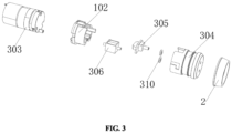
FIG. 3 is an exploded diagram of a detection portion of the present disclosure; -
FIG. 4 is an exploded diagram of a battery portion of the present disclosure; -
FIG. 5 is a schematic diagram of a side-view structure of the present disclosure; -
FIG. 6 is a schematic diagram of an internal structure of the present disclosure; -
FIG. 7 is a schematic diagram of connection between a detection box and a shell of the present disclosure; -
FIG. 8 is a schematic structural diagram of a mounting barrel of the present disclosure; and -
FIG. 9 is a sectional view of an air pump and a vacuum suction cup of the present disclosure. - In the drawings: 1: shell; 101: mounting block; 102: connecting plate; 2: sealing ring; 3: automatic air replenishing mechanism; 301: battery mounting box; 302: battery pack; 303: vacuum pump; 304: detection box; 305: air pressure sensor; 306: two-way valve; 307: digital display circuit board; 308: digital display board; 309: switch; 310: O-ring; 311: hose; 312: mounting slot; 4: mounting barrel; and 401: round hole.
- The technical solutions in the embodiments of present disclosure are clearly and completely described below with reference to the accompanying drawings in the embodiments of present disclosure. Apparently, the described embodiments are merely some rather than all of the embodiments of present disclosure. All other embodiments obtained by a person of ordinary skill in the art based on the embodiments of present disclosure without making creative efforts shall fall within the protection scope of present disclosure.
- During specific implementation, as shown in
FIG. 1 to FIG. 9 , an air pump with an automatic air pumping function includes ashell 1 and asealing ring 2; an automaticair replenishing mechanism 3 is arranged at one end of theshell 1; amounting barrel 4 sleeves the other end of theshell 1; the automaticair replenishing mechanism 3 includes abattery mounting box 301 mounted on an inner wall of theshell 1; abattery pack 302 is arranged inside thebattery mounting box 301; avacuum pump 303 is arranged on the inner wall of theshell 1; one end of theshell 1 is clamped with adetection box 304; anair pressure sensor 305 is arranged inside thedetection box 304; a two-way valve 306 communicated with thevacuum pump 303 is embedded into the other end of thedetection box 304; the sealingring 2 sleeves a surface of thedetection box 304; a shape of thesealing ring 2 is a hollow circular truncated cone; a digitaldisplay circuit board 307 is arranged on a surface of thebattery mounting box 301; and an output end of thebattery pack 302 is electrically connected to an input end of the digitaldisplay circuit board 307. During transferring of tiles or when a vacuum suction cup and an air pump need to be used in other aspects, the vacuum suction cup and the air pump are first mounted using thesealing ring 2. The device is first used to make the vacuum suction cup in a set negative pressure state. During use, theair pressure sensor 305 can monitor an air pressure in real time. If an air pressure value is less than a preset value, theair pressure sensor 305 may transmit a signal to the digitaldisplay circuit board 307. The digitaldisplay circuit board 307 transmits the signal to thevacuum pump 303, and thebattery pack 302 provides a driving force for thevacuum pump 303. The two-way valve 306 is used for air pumping, so that an internal pressure reaches a preliminary preset value, and a negative pressure state is achieved. - During use of the device, the automatic
air replenishing mechanism 3 in the device can use theair pressure sensor 305 to automatically detect an air pressure in an inner cavity of the suction cup; when the air pressure value changes, the intensity of the negative pressure will change; thevacuum pump 303 automatically runs to pump air from the device; and meanwhile, theair pressure sensor 305 can make air pumping more intelligent, and the process runs automatically during the use of the device without manual control, so that tiles will not be separated from the vacuum suction cup during transportation or laying. - As shown in
FIG. 1 to FIG. 8 , the automaticair replenishing mechanism 3 further includes adigital display board 308 arranged on a surface of themounting barrel 4; thedigital display board 308 and the digitaldisplay circuit board 307 are electrically connected in both directions; the other end of themounting barrel 4 is provided with aswitch 309; and theswitch 309 is electrically connected to thebattery pack 302. Thedigital display board 308 can display values such as the air pressure value, and an operator can also view states more intuitively. This makes the device more convenient to use. At the same time, to facilitate a user to use the product, when a battery runs out during electric air pumping, the user can use a manual air pumping function. An O-ring 310 is arranged on a surface of an end portion of the two-way valve 306; an outer wall of the O-ring 310 is in close contact with thedetection box 304; and the O-ring 310 is a rubber material member. - A
hose 311 is arranged between the two-way valve 306 and thevacuum pump 303, and an end portion of thehose 311 penetrates through thedetection box 304. Thehose 311 can be disassembled and removed according to a situation, so that the device is more convenient to disassemble. The inner wall of theshell 1 is fixedly connected with two mountingblocks 101; and two L-shaped mountingslots 312 matched with the mountingblocks 101 are formed in the surface of thedetection box 304. The mounting blocks 101 are first placed at notches of the L-shaped mountingslots 312. After movement for a period of time, thedetection box 304 is rotated to achieve the mounting operation, making mounting and removal more convenient. - A negative pressure value of the
air pressure sensor 305 is between 500 MMhg and 200 MMhg. The inner wall of theshell 1 is provided with a connectingplate 102; and the connectingplate 102 is connected to one end of thevacuum pump 303. Around hole 401 is formed in a middle position of the other end of the mountingbarrel 4, and a size of theround hole 401 is matched with a size of theswitch 309. Theair pressure sensor 305 is electrically connected to the digitaldisplay circuit board 307; and a sensing range of theair pressure sensor 305 is from 0 kPa to 90 kPa at a negative pressure. - During use of the present disclosure, during transferring of tiles or when a vacuum suction cup and an air pump need to be used in other aspects, the vacuum suction cup and the air pump are first mounted using the
sealing ring 2. The device is first used to make the vacuum suction cup in a set negative pressure state. During use, theair pressure sensor 305 can monitor an air pressure in real time. If an air pressure value is less than a preset value, theair pressure sensor 305 may transmit a signal to the digitaldisplay circuit board 307. The digitaldisplay circuit board 307 transmits the signal to thevacuum pump 303, and thebattery pack 302 provides a driving force for thevacuum pump 303. The two-way valve 306 is used for air pumping, so that an internal pressure reaches a preliminary preset value, and a negative pressure state is achieved. Meanwhile, thedigital display board 308 can display values such as the air pressure value, and an operator can also view states more intuitively. This makes the device more convenient to use. - It should be noted that the battery pack, the vacuum pump, the air pressure sensor, the two-way valve, the digital display circuit board, and the digital display board mentioned in the above descriptions are all mature devices applied in the prior art. Specific models can be selected according to actual needs. At the same time, the battery pack, the vacuum pump, the air pressure sensor, the two-way valve, the digital display circuit board, and the digital display board can be powered by a built-in power source or a mains supply. A specific power supplying way depends on a situation, and will not be elaborate here.
- In addition, it should be understood that although this specification is described according to the implementations, not each implementation only includes one independent technical solution. This narration method of this specification is only for clarity. A person skilled in the art should regard this specification as a whole, and the technical solutions in the respective embodiments can also be appropriately combined to form other implementations that can be understood by a person skilled in the art.
Claims (9)
- An air pump with an automatic air pumping function, comprising a shell (1) and a sealing ring (2), wherein an automatic air replenishing mechanism (3) is arranged at one end of the shell (1), and the other end of the shell (1) is sleeved with a mounting barrel (4);
the automatic air replenishing mechanism (3) comprises a battery mounting box (301) mounted on an inner wall of the shell (1); a battery pack (302) is arranged inside the battery mounting box (301); a vacuum pump (303) is arranged on the inner wall of the shell (1); one end of the shell (1) is clamped with a detection box (304); an air pressure sensor (305) is arranged inside the detection box (304); a two-way valve (306) communicated with the vacuum pump (303) is embedded into the other end of the detection box (304); the sealing ring (2) sleeves a surface of the detection box (304); a shape of the sealing ring (2) is a hollow circular truncated cone; a digital display circuit board (307) is arranged on a surface of the battery mounting box (301); and an output end of the battery pack (302) is electrically connected to an input end of the digital display circuit board (307). - The air pump with the automatic air pumping function according to claim 1, wherein the automatic air replenishing mechanism (3) further comprises a digital display board (308) arranged on a surface of the mounting barrel (4); the digital display board (308) and the digital display circuit board (307) are electrically connected in both directions; the other end of the mounting barrel (4) is provided with a switch (309); and the switch (309) is electrically connected to the battery pack (302).
- The air pump with the automatic air pumping function according to claim 1, wherein an O-ring (310) is arranged on a surface of an end portion of the two-way valve (306); an outer wall of the O-ring (310) is in close contact with the detection box (304); and the O-ring (310) is a rubber material member.
- The air pump with the automatic air pumping function according to claim 1, wherein a hose (311) is arranged between the two-way valve (306) and the vacuum pump (303), and an end portion of the hose (311) penetrates through the detection box (304).
- The air pump with the automatic air pumping function according to claim 1, wherein the inner wall of the shell (1) is fixedly connected with two mounting blocks (101); and two L-shaped mounting slots (312) matched with the mounting blocks (101) are formed in the surface of the detection box (304).
- The air pump with the automatic air pumping function according to claim 1, wherein the negative pressure value of the air pressure sensor (305) ranges from 0 kPa to 90 kPa.
- The air pump with the automatic air pumping function according to claim 1, wherein the inner wall of the shell (1) is provided with a connecting plate (102); and the connecting plate (102) is connected to one end of the vacuum pump (303).
- The air pump with the automatic air pumping function according to claim 1, wherein a round hole (401) is formed in a middle position of the other end of the mounting barrel (4), and a size of the round hole (401) is matched with a size of the switch (309).
- The air pump with the automatic air pumping function according to claim 1, wherein the air pressure sensor (305) is electrically connected to the digital display circuit board (307); and a sensing range of the air pressure sensor (305) is from 0 kPa to 90 kPa at a negative pressure.
Priority Applications (1)
| Application Number | Priority Date | Filing Date | Title |
|---|---|---|---|
| MA71467A MA71467A (en) | 2023-11-19 | 2024-01-26 | AIR PUMP WITH AUTOMATIC AIR PUMPING FUNCTION |
Applications Claiming Priority (1)
| Application Number | Priority Date | Filing Date | Title |
|---|---|---|---|
| US18/513,574 US11939973B1 (en) | 2023-11-19 | 2023-11-19 | Air pump with automatic air pumping function |
Publications (2)
| Publication Number | Publication Date |
|---|---|
| EP4556651A1 true EP4556651A1 (en) | 2025-05-21 |
| EP4556651B1 EP4556651B1 (en) | 2026-02-25 |
Family
ID=89767356
Family Applications (1)
| Application Number | Title | Priority Date | Filing Date |
|---|---|---|---|
| EP24154098.8A Active EP4556651B1 (en) | 2023-11-19 | 2024-01-26 | Air pump with automatic air pumping function |
Country Status (3)
| Country | Link |
|---|---|
| US (1) | US11939973B1 (en) |
| EP (1) | EP4556651B1 (en) |
| MA (1) | MA71467A (en) |
Families Citing this family (1)
| Publication number | Priority date | Publication date | Assignee | Title |
|---|---|---|---|---|
| USD1124031S1 (en) * | 2024-04-22 | 2026-04-28 | Suzhou Cainiao Home Products Co., LTD | Wireless pump |
Citations (6)
| Publication number | Priority date | Publication date | Assignee | Title |
|---|---|---|---|---|
| DE102007031760B4 (en) * | 2007-07-07 | 2011-03-17 | Festo Ag & Co. Kg | Vacuum handling device |
| US10173483B2 (en) * | 2014-11-25 | 2019-01-08 | TorrX, Inc. | Automatic electronic air pump |
| US10464216B2 (en) * | 2017-09-12 | 2019-11-05 | Kabushiki Kaisha Toshiba | Object holding apparatus with suction device and proximal sensor |
| US10625955B2 (en) * | 2018-06-11 | 2020-04-21 | Tkt Corporation | Electric vacuum suction lifter |
| EP3957442A1 (en) * | 2020-08-20 | 2022-02-23 | TRUMPF Schweiz AG | Handling device and method for removing a workpiece part produced from a plate-shaped material by means of cutting |
| US20220288795A1 (en) * | 2018-05-08 | 2022-09-15 | Nemo Power Tools, Ltd. | Extended-Frame Portable Vacuum Gripper |
Family Cites Families (11)
| Publication number | Priority date | Publication date | Assignee | Title |
|---|---|---|---|---|
| US2960321A (en) * | 1957-09-06 | 1960-11-15 | Jr William L Stoots | Portable aerator |
| US4033511A (en) * | 1975-11-24 | 1977-07-05 | Chamberlin Edward B | Portable atomizer apparatus |
| US5127808A (en) * | 1991-01-14 | 1992-07-07 | Alan Nichols | Portable air pump |
| DK168644B1 (en) * | 1993-03-09 | 1994-05-09 | Peter Egelund Soerensen | Portable, battery operated air pump |
| JP3427383B1 (en) * | 2002-04-08 | 2003-07-14 | 有限会社ケー・エム・シー | Piston pump |
| US7556478B2 (en) * | 2004-06-30 | 2009-07-07 | Campbell Hausfeld/Scott Fetzer Company | Compressor control apparatus |
| US7128525B2 (en) | 2004-12-29 | 2006-10-31 | Ho Lee Co., Ltd. | Air pump |
| US20090010774A1 (en) * | 2007-07-02 | 2009-01-08 | Fish Robert D | Air Compressor and Reservoir For Topping Off Low Pressure Tires |
| JP5144553B2 (en) | 2009-01-30 | 2013-02-13 | 日東工器株式会社 | air pump |
| TWM436728U (en) | 2012-01-20 | 2012-09-01 | Jiao Hsiung Industry Corp | Inflating device |
| JP7091171B2 (en) * | 2018-07-05 | 2022-06-27 | 株式会社マキタ | Portable inflator |
-
2023
- 2023-11-19 US US18/513,574 patent/US11939973B1/en active Active
-
2024
- 2024-01-26 EP EP24154098.8A patent/EP4556651B1/en active Active
- 2024-01-26 MA MA71467A patent/MA71467A/en unknown
Patent Citations (6)
| Publication number | Priority date | Publication date | Assignee | Title |
|---|---|---|---|---|
| DE102007031760B4 (en) * | 2007-07-07 | 2011-03-17 | Festo Ag & Co. Kg | Vacuum handling device |
| US10173483B2 (en) * | 2014-11-25 | 2019-01-08 | TorrX, Inc. | Automatic electronic air pump |
| US10464216B2 (en) * | 2017-09-12 | 2019-11-05 | Kabushiki Kaisha Toshiba | Object holding apparatus with suction device and proximal sensor |
| US20220288795A1 (en) * | 2018-05-08 | 2022-09-15 | Nemo Power Tools, Ltd. | Extended-Frame Portable Vacuum Gripper |
| US10625955B2 (en) * | 2018-06-11 | 2020-04-21 | Tkt Corporation | Electric vacuum suction lifter |
| EP3957442A1 (en) * | 2020-08-20 | 2022-02-23 | TRUMPF Schweiz AG | Handling device and method for removing a workpiece part produced from a plate-shaped material by means of cutting |
Also Published As
| Publication number | Publication date |
|---|---|
| US20240084791A1 (en) | 2024-03-14 |
| EP4556651B1 (en) | 2026-02-25 |
| US11939973B1 (en) | 2024-03-26 |
| MA71467A (en) | 2025-04-30 |
Similar Documents
| Publication | Publication Date | Title |
|---|---|---|
| EP4556651B1 (en) | Air pump with automatic air pumping function | |
| US12535076B2 (en) | Automatic vacuum sealer | |
| CN108688971B (en) | Intelligent vacuum storage tank | |
| CN202768320U (en) | Handheld electric vacuum pump | |
| CN217807388U (en) | Electric vacuum chuck | |
| CN212502817U (en) | Hand-held carrying device | |
| CN120207671A (en) | Mason jar sealers | |
| CN221070057U (en) | Novel multi-functional electronic sucking disc | |
| CN112828927A (en) | Vacuum chuck with built-in intelligent control software unit | |
| CN212774636U (en) | Electric vacuum extractor capable of detecting air pressure | |
| CN215457175U (en) | Multifunctional vacuum storage box | |
| CN214931989U (en) | A kind of fresh fruit box with high stability | |
| CN108773579A (en) | A kind of intelligent vacuum holding vessel | |
| CN214566410U (en) | Vacuum device capable of automatically taking off line | |
| CN218899251U (en) | A vacuum grain storage barrel with automatic induction pumping | |
| CN211259971U (en) | A portable breast pump and its base | |
| CN202273838U (en) | Household vacuum machine | |
| CN120946538A (en) | electric vacuum pump | |
| CN221138784U (en) | Vacuum extractor suitable for big and small bottle openings | |
| CN217792538U (en) | Extraction machine | |
| CN211839239U (en) | Portable Pressure Washer | |
| CN223209827U (en) | Glue supply device for preventing glue leakage | |
| CN221139421U (en) | A vacuum pump with negative pressure detection | |
| CN210794302U (en) | Negative pressure self-sustaining vacuum tank | |
| CN104668148A (en) | Automatic gel filling equipment |
Legal Events
| Date | Code | Title | Description |
|---|---|---|---|
| PUAI | Public reference made under article 153(3) epc to a published international application that has entered the european phase |
Free format text: ORIGINAL CODE: 0009012 |
|
| STAA | Information on the status of an ep patent application or granted ep patent |
Free format text: STATUS: REQUEST FOR EXAMINATION WAS MADE |
|
| 17P | Request for examination filed |
Effective date: 20240126 |
|
| AK | Designated contracting states |
Kind code of ref document: A1 Designated state(s): AL AT BE BG CH CY CZ DE DK EE ES FI FR GB GR HR HU IE IS IT LI LT LU LV MC ME MK MT NL NO PL PT RO RS SE SI SK SM TR |
|
| RIN1 | Information on inventor provided before grant (corrected) |
Inventor name: XU, SHUAIJIE |
|
| GRAP | Despatch of communication of intention to grant a patent |
Free format text: ORIGINAL CODE: EPIDOSNIGR1 |
|
| STAA | Information on the status of an ep patent application or granted ep patent |
Free format text: STATUS: GRANT OF PATENT IS INTENDED |
|
| INTG | Intention to grant announced |
Effective date: 20250917 |
|
| GRAS | Grant fee paid |
Free format text: ORIGINAL CODE: EPIDOSNIGR3 |
|
| GRAA | (expected) grant |
Free format text: ORIGINAL CODE: 0009210 |
|
| STAA | Information on the status of an ep patent application or granted ep patent |
Free format text: STATUS: THE PATENT HAS BEEN GRANTED |
|
| RAV | Requested validation state of the european patent: fee paid |
Extension state: GE Effective date: 20260114 Extension state: KH Effective date: 20240126 Extension state: MA Effective date: 20240126 Extension state: MD Effective date: 20240126 Extension state: TN Effective date: 20240126 |
|
| AK | Designated contracting states |
Kind code of ref document: B1 Designated state(s): AL AT BE BG CH CY CZ DE DK EE ES FI FR GB GR HR HU IE IS IT LI LT LU LV MC ME MK MT NL NO PL PT RO RS SE SI SK SM TR |
|
| REG | Reference to a national code |
Ref country code: CH Ref legal event code: F10 Free format text: ST27 STATUS EVENT CODE: U-0-0-F10-F00 (AS PROVIDED BY THE NATIONAL OFFICE) Effective date: 20260225 Ref country code: GB Ref legal event code: FG4D |
|
| REG | Reference to a national code |
Ref country code: DE Ref legal event code: R096 Ref document number: 602024002709 Country of ref document: DE |
|
| REG | Reference to a national code |
Ref country code: IE Ref legal event code: FG4D |