EP4556647A2 - A method for mounting a roof window, a kit for use in the method, and a roof window - Google Patents
A method for mounting a roof window, a kit for use in the method, and a roof window Download PDFInfo
- Publication number
- EP4556647A2 EP4556647A2 EP25168586.3A EP25168586A EP4556647A2 EP 4556647 A2 EP4556647 A2 EP 4556647A2 EP 25168586 A EP25168586 A EP 25168586A EP 4556647 A2 EP4556647 A2 EP 4556647A2
- Authority
- EP
- European Patent Office
- Prior art keywords
- flashing
- frame
- members
- frame member
- extending
- Prior art date
- Legal status (The legal status is an assumption and is not a legal conclusion. Google has not performed a legal analysis and makes no representation as to the accuracy of the status listed.)
- Pending
Links
Images


Classifications
-
- E—FIXED CONSTRUCTIONS
- E04—BUILDING
- E04D—ROOF COVERINGS; SKY-LIGHTS; GUTTERS; ROOF-WORKING TOOLS
- E04D13/00—Special arrangements or devices in connection with roof coverings; Protection against birds; Roof drainage ; Sky-lights
- E04D13/03—Sky-lights; Domes; Ventilating sky-lights
- E04D13/0305—Supports or connecting means for sky-lights of flat or domed shape
- E04D13/031—Supports or connecting means for sky-lights of flat or domed shape characterised by a frame for connection to an inclined roof
-
- E—FIXED CONSTRUCTIONS
- E04—BUILDING
- E04D—ROOF COVERINGS; SKY-LIGHTS; GUTTERS; ROOF-WORKING TOOLS
- E04D13/00—Special arrangements or devices in connection with roof coverings; Protection against birds; Roof drainage ; Sky-lights
- E04D13/03—Sky-lights; Domes; Ventilating sky-lights
- E04D13/035—Sky-lights; Domes; Ventilating sky-lights characterised by having movable parts
- E04D13/0351—Sky-lights; Domes; Ventilating sky-lights characterised by having movable parts the parts pivoting about a fixed axis
- E04D13/0354—Sky-lights; Domes; Ventilating sky-lights characterised by having movable parts the parts pivoting about a fixed axis the parts being flat
-
- E—FIXED CONSTRUCTIONS
- E04—BUILDING
- E04D—ROOF COVERINGS; SKY-LIGHTS; GUTTERS; ROOF-WORKING TOOLS
- E04D13/00—Special arrangements or devices in connection with roof coverings; Protection against birds; Roof drainage ; Sky-lights
- E04D13/14—Junctions of roof sheathings to chimneys or other parts extending above the roof
- E04D13/147—Junctions of roof sheathings to chimneys or other parts extending above the roof specially adapted for inclined roofs
- E04D13/1473—Junctions of roof sheathings to chimneys or other parts extending above the roof specially adapted for inclined roofs specially adapted to the cross-section of the parts extending above the roof
- E04D13/1475—Junctions of roof sheathings to chimneys or other parts extending above the roof specially adapted for inclined roofs specially adapted to the cross-section of the parts extending above the roof wherein the parts extending above the roof have a generally rectangular cross-section
Definitions
- the present invention relates to a method for mounting a roof window in a roof structure comprising a roofing material, said roof window comprising a frame, a sash carrying a pane element, and said frame comprising a top frame member, two side frame members and a bottom frame member, said frame members together defining a frame opening and a frame plane and each extending in a length direction and each having an outer side facing away from the frame opening, where said method comprises the steps of: A) Arranging the roof window in an opening in the roof structure, and B) Arranging a plurality of flashing members so that they cover a joint between the frame of the roof window and the roof structure with a top flashing member extending along the top frame member, a bottom flashing member extending along the bottom frame member, and at least two side flashing members extending along the side frame members, each flashing member being arranged with an inner section adjacent to a frame member and an outer section extending from the inner section away from the frame.
- the invention further relates to a kit for use in the method
- the side flashing members By inserting flanges of the side flashing members in one or more flashing reception recesses, such as grooves, extending in the length direction of the side frame members, the side flashing members can be arranged precisely in the intended height in a height direction extending perpendicular to the frame plane. This ensures that the side flashing members are arranged in the intended height in relation to the roof structure and may also contribute to neighbouring flashing members being arranged correctly in relation to each other. As is well-known to the skilled person, neighbouring flashing members typically overlap and a tight contact between the overlapping parts of the flashing members may contribute to the tightness of the finished covering assembly. For this purpose, two or more flashing members may be arranged so that their flanges project into the same flashing reception recess and so that the flanges overlap inside the flashing reception recess.
- the flashing members are displaced in a direction parallel to the frame plane for insertion of the flanges into the flashing reception recess(s).
- the flange extends in a direction parallel to the frame plane in the mounted state. This will for example allow a flange on a corner section of a top flashing member to be inserted into the same flashing reception recess in a side frame member as a side flashing member by displacement of the top flashing member in a direction parallel to the side frame member.
- Other insertion angles are, however, possible, depending for example on the shape of the side flashing members and on how deep in the roof structure the roof window is mounted, including a swinging motion, where the side flashing member are turned about the length direction during insertion.
- the shaping may be done by hand or using a tool, such as rubber hammer. Flashing members made from aluminium can usually be deformed by hand, by simply pushing them firmly against the roofing material and/or roof structure.
- the flange may comprise a marking indicating an intended insertion depth of the flange into the flashing reception recess.
- the marking may for example be a printed indication on the flange but may also be in the form of perforations or projections on the flange. Perforations may have the added advantage of reducing heat transfer via the flange. It is also possible to provide a click-function providing an audio and/or tactile feed-back when proper insertion has been achieved.
- the method may comprise the further step of D) displacing the side flashing member in a direction parallel with the length direction of the side frame member following step B) and before step C), if applicable.
- This step may be performed to achieve an overlap between flashing members, for example for interconnecting gutters into one continuous gutter as described above.
- the object is achieved with a kit for mounting a roof window using the method described above, comprising a roof window, a plurality of flashing members, and a tool for retaining the inner sections of the side flashing members during a shaping of the outer sections of flashing members.
- the roof window 1 comprises a frame (not visible in Fig. 1 ), and the top flashing member 1011, the side flashing members 1012, 1013, and the bottom flashing member 1014 extend in a respective length direction L along top, side and frame members, respectively.
- the frame members together defining a frame opening covered by the pane element 4 and a frame plane F.
- a lowermost side flashing members 1013a is mounted at the left-hand side of the roof window by upwards displacement along the direction of inclination I of the roof structure 11, inserting the flange 1017 into a flashing reception recess in the form of a groove in an interface unit 8 arranged on the side frame member.
- the lowermost side flashing members 1012a for use at the right-hand side of the roof window is shown in Fig. 6 .
- Fig. 4 the outer section 1013o, which was initially in an upright state as shown in Fig. 3 , is bent down by hand, thereby bringing it into contact with the roofing material 112, which is here slate, thus shaping the lowermost side flashing members 1013a to the shape of the roofing material.
- a closure flap 1013c is bent downwards towards the bottom flashing member 1014, thereby contributing to water-proofing the joint between flashing members and to ensuring the position of the side flashing member 1013a.
- the corresponding closure flap 1012c on the right-hand side flashing member 1012a is more easily seen.
- the lowermost side flashing members 1012a comprises a gutter 1012g, extending in parallel with the flange 1017 and thus with the side frame member in the mounted state, and a series of perforations 1017i in the flange. Both will be described in further detail below.
- the remaining side flashing members 1012, 1013 are mounted by being displaced from the side, i.e. in a direction perpendicular to the side frame member as shown in Fig. 7 .
- several side flashing members are used at each side of the roof window 1, but it is to be understood that the invention also applies to roof windows where the covering assembly only comprises two regular side flashing members 1012, 1013, one at each side of the roof window.
- the side flashing members shown in Fig. 7 are initially mounted in a state, where an outer section 1012o, 1013o configured for resting on the roof structure 11 is in an upright position, and the outer section is then folded down onto the roofing material 112 as shown in Fig. 8 or in Fig. 9 , ending up having the shape shown in Fig. 10 .
- This embodiment is particularly well suited for use with flat roofing materials, such as slate, whereas flashing members used with undulating roofing materials, such as tiles, will typically project underneath the roofing material and may therefore be mounted without such a folding down step.
- the folding down may, however, also be used for adapting the shape of the side flashing member to the shape of a roof structure supporting an undulating roofing material.
- the folding down may be performed by hand as in Fig. 4 , by use of a rubber hammer as shown in Fig. 8 , or by use of a specialized tool as in Fig. 9 .
- the specialized tool is here arranged on the part of the outer section bordering the gutter (not visible in Fig. 9 ), thereby hindering a deformation of the side of the gutter closest to the outer section. It is, however, also possible to arrange the tool in the gutter, thereby keeping the gutter in place during the shaping and possibly preventing a deformation of the gutter.
- a flange 1017 on the side flashing member 1012 has been inserted into a flashing reception recess 85 in the form of a groove in a side element 82 of an interface unit of the frame 2, and it is to be understood that both the interface unit and the flashing reception recess 85 therein extends in the length direction L of the frame side member 22.
- elastic protrusions 85a engage with both sides of the flange 1017, thereby contributing to keeping it in place in the flashing reception recess.
- the protrusions may also serve a sealing function. If inserting the flange in a flashing reception recess in a traditional frame member, similar protrusions may be provided by inserting a gasket in the flashing reception recess before inserting the flange.
- the flashing reception recess 85 has a height allowing it to accommodate at least two flanges of side flashing members overlapping each other as here shown by the broken line illustrating and overlap with a top flashing member 1011. Side flashing members may overlap in the same way. In this way a continuous gutter extending all the way along the side of the roof window may be formed.
- FIG. 11 An example of a side flashing member 1012 is shown in Fig. 11 .
- the gutter 1012g, and the flange 1017 has a series of marking 1017i in the flange as also mentioned with reference to Fig. 6 .
- markings serve as a visual indication if the flange has been inserted sufficiently deep into the flashing reception recess 85 for the side flashing member to be in the intended position.
- the markings will be aligned with the side of the interface unit at correct insertion, but they may also be positioned such that they are to be hidden inside the flashing reception recess at correct insertion. This particularly advantageous if the markings are perforations. Printed lines or dots, depressions, projections, or other similar markings may also be used.
- Fig. 13 the mounting of the top flashing member 1011 is shown. As may be seen, it is mounted in the same way as described with reference to the bottom flashing member in the description of Fig. 2 , only displacing it downwards instead of upwards as seen in the direction of inclination I of the roof structure 11.
- corners section 1011a of the top flashing member 1011 can be in an upright initial state as described above or be bent to this state before mounting. They may, however, also be in an initial state requiring less deformation as shown at the right-hand side in Fig. 1 and in Fig. 13 .
- the corner sections 1011a are folded down onto the roofing material 112 in the same way as described with reference to the outer sections of the side flashing members.
- the folding is shown as being done by hand, but it could also be done using a tool.
- the top flashing member 1014 also comprises gutters 1011g, which in the mounted state are arranged in continuation of the gutters 1012g, 1013g in the side flashing members 1012, 1013. In the mounted state these gutters 1011g, 1012g, 1013g thus form one continuous gutter allowing water to be drained down along the sides of the roof window 1.
- Gutter 1011g, 1012g, 1013g may contribute to a correct alignment of the flashing members in relation to each other.
- each component may in principle be reused, be recycled by appropriate environmentally responsible disposal means, or the material be recovered for other uses.
Landscapes
- Engineering & Computer Science (AREA)
- Architecture (AREA)
- Civil Engineering (AREA)
- Structural Engineering (AREA)
- Roof Covering Using Slabs Or Stiff Sheets (AREA)
- Conveying And Assembling Of Building Elements In Situ (AREA)
Abstract
Description
- The present invention relates to a method for mounting a roof window in a roof structure comprising a roofing material, said roof window comprising a frame, a sash carrying a pane element, and said frame comprising a top frame member, two side frame members and a bottom frame member, said frame members together defining a frame opening and a frame plane and each extending in a length direction and each having an outer side facing away from the frame opening, where said method comprises the steps of: A) Arranging the roof window in an opening in the roof structure, and B) Arranging a plurality of flashing members so that they cover a joint between the frame of the roof window and the roof structure with a top flashing member extending along the top frame member, a bottom flashing member extending along the bottom frame member, and at least two side flashing members extending along the side frame members, each flashing member being arranged with an inner section adjacent to a frame member and an outer section extending from the inner section away from the frame. The invention further relates to a kit for use in the method and to a roof window.
- When installing windows in a roof structure of a building it is necessary to make an opening in the roof structure and subsequently to re-establish the weather proofing of the building otherwise provided by the roof structure. For this purpose, the joint between the roof window and the roof structure is covered by covering assembly including flashing and cladding members. To achieve the best possible weather proofing it is essential that the covering assembly is mounted correctly and that it subsequently stays in place, even during heavy winds and when affected by big temperature variations.
- With this background, it is therefore an object of the invention to provide an improved method for mounting a roof window with a covering assembly and a roof window with an improved covering assembly.
- This and further objects are achieved with a method of the kind mentioned in the introduction which is furthermore characterised in that during step B) a flange of at least one side flashing member is inserted into a flashing reception recess in the outer side of at least one side frame member, said flashing reception recess extending in the length direction of the side frame member.
- By inserting flanges of the side flashing members in one or more flashing reception recesses, such as grooves, extending in the length direction of the side frame members, the side flashing members can be arranged precisely in the intended height in a height direction extending perpendicular to the frame plane. This ensures that the side flashing members are arranged in the intended height in relation to the roof structure and may also contribute to neighbouring flashing members being arranged correctly in relation to each other. As is well-known to the skilled person, neighbouring flashing members typically overlap and a tight contact between the overlapping parts of the flashing members may contribute to the tightness of the finished covering assembly. For this purpose, two or more flashing members may be arranged so that their flanges project into the same flashing reception recess and so that the flanges overlap inside the flashing reception recess.
- It is presently considered advantageous that the flashing members are displaced in a direction parallel to the frame plane for insertion of the flanges into the flashing reception recess(s). For this purpose, the flange extends in a direction parallel to the frame plane in the mounted state. This will for example allow a flange on a corner section of a top flashing member to be inserted into the same flashing reception recess in a side frame member as a side flashing member by displacement of the top flashing member in a direction parallel to the side frame member. Other insertion angles are, however, possible, depending for example on the shape of the side flashing members and on how deep in the roof structure the roof window is mounted, including a swinging motion, where the side flashing member are turned about the length direction during insertion.
- The flashing reception recess may be provided in a traditional frame member, such as a wooden frame member, a frame member made from a wood-based core encased in a polymer, or a frame member made by extrusion, but is also possible to provide the frame with an interface unit and forming the flashing reception recess therein. The interface unit may for example be an elongate member, such as a rail, provided on an exterior side of a traditional frame member and extending in the length direction thereof.
- In one embodiment, the method further comprises the step of: C) shaping the outer sections of the side flashing members so that they match the shape of the roof structure and/or the roof material. The side flashings may then for example be provided with the outer section extending perpendicular to the flange and be arranged with the outer section initially extending perpendicular to the frame plane. This may for example be advantageous in roofs with a flat roofing material, such as slate, where it is common practice to use several smaller side flashing members, which are arranged alternating with plates of slate. A plate of slate can then be arranged while the outer section projects upwards, perpendicular to the frame plane and to the plane of the roof, and the outer section can then be folded down onto the plate of slate and shaped to follow it precisely. In this way it is possible to not only compensate for natural variations in the shape of the roofing material, but also to compensate for smaller differences in the height of the roofing material relative to the position of the roof window and hence the flashing reception recess, which may for example result from different building traditions, such as the use of laths of different dimensions in different countries. Shaping of the outer section may also be advantageous where the roofing material is an undulating roofing material, such as tiles, where the side flashing members will typically project underneath the roofing material. The shaping may then be used for adapting the shape of the side flashing member to the shape of the roof structure supporting the roofing material.
- Depending on the material used for the flashing members, the shaping may be done by hand or using a tool, such as rubber hammer. Flashing members made from aluminium can usually be deformed by hand, by simply pushing them firmly against the roofing material and/or roof structure.
- The top and/or bottom flashing member may be provided with corner sections extending in continuation of the side flashing members when seen in the direction of inclination of the roof structure, and it may also be advantageous to shape such corner sections as described with reference to the side flashing members above.
- In one embodiment, three or more side flashing members are inserted into the flashing reception recess in the outer side of each side frame member, and each side flashing member is arranged so that it overlaps with another side flashing member. If, in that case, the inner section of each side flashing member comprises a gutter extending in the length direction and said gutter has the same depth over the entire extend of the side flashing member and the same depth in all side flashing members, a continuous gutter extending along length of the side frame member can formed. From a distance, for example if view by a person standing on the ground and looking up on the roof, this gutter may appear as being formed by a single side flashing member.
- To facilitate mounting of the flashing member, the flange may comprise a marking indicating an intended insertion depth of the flange into the flashing reception recess. During mounting, the displacing of the flashing member is continued until the flange is inserted so deep in the flashing reception recess that the marking reaches or is hidden by the side frame member. The marking may for example be a printed indication on the flange but may also be in the form of perforations or projections on the flange. Perforations may have the added advantage of reducing heat transfer via the flange. It is also possible to provide a click-function providing an audio and/or tactile feed-back when proper insertion has been achieved.
- Alternatively, or additionally, if the inner section of the side flashing member comprises a gutter extending in the length direction and configured for extending along a side frame member between the frame and the roofing material in the mounted state, it is possible to continue the insertion of the flange until the gutter engages with the outer side of a side frame member.
- The method may comprise the further step of D) displacing the side flashing member in a direction parallel with the length direction of the side frame member following step B) and before step C), if applicable. This step may be performed to achieve an overlap between flashing members, for example for interconnecting gutters into one continuous gutter as described above.
- To facilitate a shaping of the outer section of a side flashing member, the inner section may be retained using a tool during step C). This may for example help to prevent the flange from being pulled out of the flashing reception recess during the shaping process and/or help to prevent a deformation of the inner section of the side flashing member.
- If the inner section comprises a gutter, the tool may be arranged in the gutter during use, and it is presently considered advantageous that the tool has a width corresponding to the width of the gutter in a direction perpendicular to the length direction, as this may help prevent deformation of the gutter. It is, however, also possible to use the tool for forming a gutter before, during, or after the shaping in step C).
- The length of the tool as measured in the length direction during use may correspond to the length of the side flashing member. Using a shorter tool may be advantageous with side flashing members extending substantially along the entire length of the side frame member. Using a longer tool may be advantageous when mounting several shorter side flashing members, where mutual adaptation may be desired. The tool may comprise a scale or length indication, which may be used for determining if an intended overlap between neighbouring flashing members has been achieved.
- In a second aspect of the invention, the object is achieved with a kit for mounting a roof window using the method described above, comprising a roof window, a plurality of flashing members, and a tool for retaining the inner sections of the side flashing members during a shaping of the outer sections of flashing members.
- In a third aspect of the invention, the object is achieved with a roof window mounted in a roof structure comprising a roofing material, said roof window comprising a frame, a sash carrying a pane element and a covering assembly, said frame comprising a top frame member, two side frame members and a bottom frame member, said frame members together defining a frame opening and a frame plane and each extending in a length direction and each having an outer side facing away from the frame opening, and said covering assembly comprising a plurality of flashing members covering a joint between the frame and the roof structure and a plurality of cladding members covering a part of the sash, where a top flashing member extends along the top frame member, a bottom flashing member extends along the bottom frame member, and at least two side flashing members extend along the side frame members, and where each flashing member is arranged with an inner section adjacent to a frame member and an outer section extending from the inner section away from the frame, characterised in that each of the side frame members comprises a flashing reception recess in the outer side, said flashing reception recess extending in the length direction of the side frame member, and that at least one side flashing member comprises a flange inserted into the flashing reception recess.
- Embodiments and advantages described with reference to one aspect of the invention also apply to the other aspects of the invention and vice versa.
- In the following description embodiments of the invention will be described with reference to the schematic drawings, in which
-
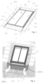
Fig. 1 is a perspective view of a roof window with a covering assembly, -
Fig. 2 is a perspective view showing the mounting of a bottom flashing member, -
Fig. 3 is a perspective view showing a first step in the mounting of a lowermost side flashing member, -
Fig. 4 is a perspective view showing a second step in the mounting of a lowermost side flashing member, -
Fig. 5 is a perspective view showing a third step in the mounting of a lowermost side flashing member, -
Fig. 6 is a perspective view of a lowermost side flashing member, -
Fig. 7 corresponds toFig. 2 but showing the subsequent mounting of side flashing members, -
Fig. 8 is a perspective view showing a further stage of the mounting of the side flashing members, -
Fig. 9 corresponds toFig. 8 but showing the use of another tool, -
Fig. 10 is a cross-sectional view showing the right-hand side flashing member in the mounted state, -
Fig. 11 is a cross-sectional view along the line IX-IX inFig. 1 , -
Fig. 12 is a perspective view of a side flashing member, -
Fig. 13 corresponds toFig. 7 but showing the subsequent mounting of a top flashing member, -
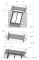
Fig. 14 is a perspective view of a top flashing member, and -
Fig. 15 is a perspective view showing a further stage of the mounting of the top flashing member. - Referring initially to
Fig. 1 , aroof window 1 is shown with a coveringassembly 10, where the right-hand side of thetop flashing member 1011 is shown in a state of delivery, before adaptation to the shape of a roofing material used alongside the roof window as will be explained later. Theroof window 1 is shown in an inclined position as it is intended for being mounted in an inclined roof structure. - In addition to the
top flashing member 1011, the covering assembly comprises a plurality ofside flashing members bottom flashing member 1014 and a plurality ofcladding members pane element 4. - The
roof window 1 comprises a frame (not visible inFig. 1 ), and thetop flashing member 1011, theside flashing members bottom flashing member 1014 extend in a respective length direction L along top, side and frame members, respectively. The frame members together defining a frame opening covered by thepane element 4 and a frame plane F. - In the embodiment in
Fig. 1 , thetop flashing member 1011 comprises acorner section 1011a at each end, said corner section extending along a side of the roof window and overlapping with a flashingmember Fig. 2 ,7 and13 ). - The
cladding members assembly 10 may be pre-mounted on theroof window 1 or be mounted after the mounting of the flashing members. This is not essential to the present invention and will therefore not be described in further detail here. - The mounting of the flashing members starts with the mounting of the
bottom flashing member 1014, and, as shown inFig. 2 , it is displaced in a direction parallel to the frame plane F and perpendicular to the length direction L of the bottom frame member 24. - In
Fig. 3 , a lowermostside flashing members 1013a is mounted at the left-hand side of the roof window by upwards displacement along the direction of inclination I of theroof structure 11, inserting theflange 1017 into a flashing reception recess in the form of a groove in aninterface unit 8 arranged on the side frame member. The lowermost side flashing members 1012a for use at the right-hand side of the roof window is shown inFig. 6 . - In
Fig. 4 the outer section 1013o, which was initially in an upright state as shown inFig. 3 , is bent down by hand, thereby bringing it into contact with theroofing material 112, which is here slate, thus shaping the lowermostside flashing members 1013a to the shape of the roofing material. - In
Fig. 5 a closure flap 1013c is bent downwards towards thebottom flashing member 1014, thereby contributing to water-proofing the joint between flashing members and to ensuring the position of theside flashing member 1013a. Thecorresponding closure flap 1012c on the right-hand side flashing member 1012a is more easily seen. - As is also seen in
Fig. 6 , the lowermost side flashing members 1012a comprises a gutter 1012g, extending in parallel with theflange 1017 and thus with the side frame member in the mounted state, and a series ofperforations 1017i in the flange. Both will be described in further detail below. - The remaining
side flashing members Fig. 7 . In the embodiment shown several side flashing members are used at each side of theroof window 1, but it is to be understood that the invention also applies to roof windows where the covering assembly only comprises two regularside flashing members - The side flashing members shown in
Fig. 7 are initially mounted in a state, where an outer section 1012o, 1013o configured for resting on theroof structure 11 is in an upright position, and the outer section is then folded down onto theroofing material 112 as shown inFig. 8 or inFig. 9 , ending up having the shape shown inFig. 10 . This embodiment is particularly well suited for use with flat roofing materials, such as slate, whereas flashing members used with undulating roofing materials, such as tiles, will typically project underneath the roofing material and may therefore be mounted without such a folding down step. The folding down may, however, also be used for adapting the shape of the side flashing member to the shape of a roof structure supporting an undulating roofing material. - The folding down may be performed by hand as in
Fig. 4 , by use of a rubber hammer as shown inFig. 8 , or by use of a specialized tool as inFig. 9 . The specialized tool is here arranged on the part of the outer section bordering the gutter (not visible inFig. 9 ), thereby hindering a deformation of the side of the gutter closest to the outer section. It is, however, also possible to arrange the tool in the gutter, thereby keeping the gutter in place during the shaping and possibly preventing a deformation of the gutter. - As may be seen in
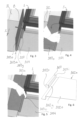
Figs 10 and11 , aflange 1017 on theside flashing member 1012 has been inserted into aflashing reception recess 85 in the form of a groove in aside element 82 of an interface unit of theframe 2, and it is to be understood that both the interface unit and theflashing reception recess 85 therein extends in the length direction L of theframe side member 22. Inside theflashing reception recess 85, elastic protrusions 85a engage with both sides of theflange 1017, thereby contributing to keeping it in place in the flashing reception recess. In addition to providing friction against the flange, the protrusions may also serve a sealing function. If inserting the flange in a flashing reception recess in a traditional frame member, similar protrusions may be provided by inserting a gasket in the flashing reception recess before inserting the flange. - The
flashing reception recess 85 has a height allowing it to accommodate at least two flanges of side flashing members overlapping each other as here shown by the broken line illustrating and overlap with atop flashing member 1011. Side flashing members may overlap in the same way. In this way a continuous gutter extending all the way along the side of the roof window may be formed. - An example of a
side flashing member 1012 is shown inFig. 11 . In addition to the outer section 1012o, the gutter 1012g, and theflange 1017, it has a series of marking 1017i in the flange as also mentioned with reference toFig. 6 . During mounting these markings serve as a visual indication if the flange has been inserted sufficiently deep into theflashing reception recess 85 for the side flashing member to be in the intended position. In the embodiment shown, the markings will be aligned with the side of the interface unit at correct insertion, but they may also be positioned such that they are to be hidden inside the flashing reception recess at correct insertion. This particularly advantageous if the markings are perforations. Printed lines or dots, depressions, projections, or other similar markings may also be used. - Turning now to
Fig. 13 the mounting of thetop flashing member 1011 is shown. As may be seen, it is mounted in the same way as described with reference to the bottom flashing member in the description ofFig. 2 , only displacing it downwards instead of upwards as seen in the direction of inclination I of theroof structure 11. - As shown in
Fig. 14 ,corners section 1011a of thetop flashing member 1011 can be in an upright initial state as described above or be bent to this state before mounting. They may, however, also be in an initial state requiring less deformation as shown at the right-hand side inFig. 1 and inFig. 13 . - As shown in
Fig. 15 , to finish the installation of the flashing members, thecorner sections 1011a are folded down onto theroofing material 112 in the same way as described with reference to the outer sections of the side flashing members. InFig. 15 the folding is shown as being done by hand, but it could also be done using a tool. - The
top flashing member 1014 also comprises gutters 1011g, which in the mounted state are arranged in continuation of the gutters 1012g, 1013g in theside flashing members roof window 1. - Gutter 1011g, 1012g, 1013g may contribute to a correct alignment of the flashing members in relation to each other.
- The
top flashing member 1011 and thebottom flashing member 1014 also comprisesflanges 1017, which are inserted into a flashing reception recess along the top frame member and the bottom frame member, respectively, as described with reference to the side flashing members above. - Components of the
roof window 1 are easily disassembled and each component may in principle be reused, be recycled by appropriate environmentally responsible disposal means, or the material be recovered for other uses. -
- 1
- Roof window
- 10
- Covering assembly
- 1011
- Top flashing member
- 1011a
- Corner section
- 1011g
- Gutter
- 1012
- Side flashing member
- 1012a
- Lowermost side flashing member
- 1012c
- Closure flap
- 1012g
- Gutter
- 1012o
- Outer section
- 1013
- Side flashing member
- 1013a
- Lowermost side flashing member
- 1013g
- Gutter
- 1013o
- Outer section
- 1014
- Bottom flashing member
- 1014a
- Corner section
- 1017
- Flange
- 1017a
- Corner flange
- 1017i
- Marking
- 1021
- Cladding member
- 1022
- Cladding member
- 1023
- Cladding member
- 1024
- Cladding member
- 11
- Roof structure
- 112
- Roofing material
- 112a
- Slate plate
- 2
- Frame
- 20o
- Outer side of frame member
- 21
- Top frame member
- 22, 23
- Side frame member
- 24
- Bottom frame member
- 200
- Frame opening
- 4
- Pane element
- 8
- Interface unit
- 81
- Top element
- 82
- Side element
- 85
- Flashing reception recess
- 85a
- Protrusion
- F
- Frame plane
- I
- Direction of inclination
- L
- Length direction
-
- 1. A method for mounting a roof window (1) in a roof structure (11) comprising a roofing material (112), said roof window comprising a frame (2), a sash (3) carrying a pane element (4), and said frame comprising a top frame member (21), two side frame members (22, 23) and a bottom frame member (24), said frame members together defining a frame opening (200) and a frame plane (F) and each extending in a length direction (L) and each having an outer side (20o) facing away from the frame opening, where said method comprises the steps of
- A) Arranging the roof window (1) in an opening in the roof structure (11),
- B) Arranging a plurality of flashing members so that they cover a joint between the frame (2) of the roof window (1) and the roof structure (11) with a top flashing member (1011) extending along the top frame member (21), a bottom flashing member (1014) extending along the bottom frame member (24), and at least two side flashing members (1012, 1013) extending along the side frame members (22, 23), each flashing member being arranged with an inner section adjacent to a frame member (21, 22, 23, 24) and an outer section extending from the inner section away from the frame,
wherein
during step B) a flange (1017) of at least one side flashing member (1012, 1013) is inserted into a flashing reception recess (85) in the outer side (20o) of at least one side frame member (22, 23), said flashing reception recess extending in the length direction (L) of the side frame member.
- 2. A method according to
item 1 where three or more side flashing members (1012, 1013) are inserted into the flashing reception recess (85) in the outer side (20o) of each side frame member (22, 23), and where each side flashing member is arranged so that it overlaps with another side flashing member. - 3. A method according to
item 2, where the inner section of each side flashing member (1012, 1013) comprises a gutter (1012g, 1013g) extending in the length direction (L), and where said gutter has the same depth over the entire extend of the side flashing member and the same depth in all side flashing members, so that when the side flashing members are mounted, a continuous gutter extending along length of the side frame member is formed. - 4. A method according to one or more of the preceding items, further comprising the step of:
C) shaping the outer sections of the side flashing members (1012, 1013) so that they match the shape of the roof structure (11) and/or the roof material (112). - 5. A method according to one or more of the preceding items, where the at least one side flashing member (1012, 1013) comprises a marking (1017i) on the flange (1017) and where the insertion of the flange in step B) is continued until the marking reaches or is hidden by the side frame member (22, 23).
- 6. A method according to one or more of the preceding items, where the inner section comprises a gutter (1012g, 1013g) extending in the length direction (L) and where the insertion of the flange (1017) in step B) is continued until the gutter engages with the outer side (20o) of the side frame member (22, 23).
- 7. A method according to one or more of the preceding items, further comprising the step of:
D) displacing the side flashing member in a direction parallel with the length direction of the side frame member following step B) and before step C), if applicable. - 8. A method according to one or more of the preceding items, where the inner section is retained using a tool (13) during step C).
- 9. A method according to
item 8, where the inner section comprises a gutter (1012g, 1013g) extending in the length direction and where the tool is arranged in the gutter. - 10. A kit for mounting a roof window using the method according to
item 8 or 9 comprising a roof window (1), a plurality of flashing members (1011, 1012, 1013, 1014), and a tool (13) for retaining the inner sections of the side flashing members (1012, 1013) during a shaping of the outer sections (1012o, 1013o) of the flashing members. - 11. A roof window (1) mounted in a roof structure (11) comprising a roofing material (112), said roof window comprising a frame (2), a sash (3) carrying a pane element (4) and a covering assembly (10), said frame comprising a top frame member (21), two side frame members (22, 23) and a bottom frame member (24), said frame members (21, 22, 23, 24) together defining a frame opening (200) and a frame plane (F) and each extending in a length direction (L) and each having an outer side (20o) facing away from the frame opening, and said covering assembly (10) comprising a plurality of flashing members (1011, 1012, 1013, 1014) covering a joint between the frame and the roof structure and a plurality of cladding members (1021, 1022) covering a part of the sash (3), where a top flashing member (1011) extends along the top frame member (21), a bottom flashing member (1014) extends along the bottom frame member (24), and at least two side flashing members (1012, 1013) extend along the side frame members (22, 23), and where each flashing member is arranged with an inner section adjacent to a frame member (21, 22, 23, 24) and an outer section extending from the inner section away from the frame,
characterised in that
each of the side frame members comprises a flashing reception recess (85) in the outer side (20o), said flashing reception recess extending in the length direction (L) of the side frame member (21, 22, 23, 24), and that at least one side flashing member (1011, 1012, 1013, 1014) comprises a flange (1017) inserted into the flashing reception recess (85). - 12. A roof window according to
item 11, where the flange (1017) extends in a direction parallel to the frame plane (F). - 13. A roof window according to
item 11 or 12, where the inner sections of at least two neighbouring flashing members (1011, 1012, 1013, 1014) comprise a gutter extending along a side frame member (22, 23) between the frame (2) and the roofing material (112) and where the gutter of these two neighbouring flashing members overlap. - 14. A roof window according to item 13, where the gutter has the same depth over the entire extend of a side flashing member and the same depth in all side flashing members.
- 15. A roof window according to one or more of items 11-14, where the flashing reception recess (85) is provided in an interface unit (8) extending in the length direction (L) of at least one frame member.
Claims (13)
- A method for mounting a roof window (1) in a roof structure (11) comprising a roofing material (112), said roof window comprising a frame (2), a sash (3) carrying a pane element (4), and said frame comprising a top frame member (21), two side frame members (22, 23) and a bottom frame member (24), said frame members together defining a frame opening (200) and a frame plane (F) and each extending in a length direction (L) and each having an outer side (20o) facing away from the frame opening, where said method comprises the steps ofA) Arranging the roof window (1) in an opening in the roof structure (11),B) Arranging a plurality of flashing members so that they cover a joint between the frame (2) of the roof window (1) and the roof structure (11) with a top flashing member (1011) extending along the top frame member (21), a bottom flashing member (1014) extending along the bottom frame member (24), and at least two side flashing members (1012, 1013) extending along the side frame members (22, 23), each flashing member being arranged with an inner section adjacent to a frame member (21, 22, 23, 24) and an outer section extending from the inner section away from the frame,C) shaping the outer sections of the side flashing members (1012, 1013) so that they match the shape of the roof structure (11) and/or the roof material (112), andD) displacing the side flashing member in a direction parallel with the length direction of the side frame member following step B) and before step C)
wherein
during step B) a flange (1017) of at least one side flashing member (1012, 1013) is inserted into a flashing reception recess (85) in the outer side (20o) of at least one side frame member (22, 23), said flashing reception recess extending in the length direction (L) of the side frame member. - A method according to claim 1 where three or more side flashing members (1012, 1013) are inserted into the flashing reception recess (85) in the outer side (20o) of each side frame member (22, 23), and where each side flashing member is arranged so that it overlaps with another side flashing member.
- A method according to claim 2, where the inner section of each side flashing member (1012, 1013) comprises a gutter (1012g, 1013g) extending in the length direction (L), and where said gutter has the same depth over the entire extend of the side flashing member and the same depth in all side flashing members, so that when the side flashing members are mounted, a continuous gutter extending along length of the side frame member is formed.
- A method according to one or more of the preceding claims, where the at least one side flashing member (1012, 1013) comprises a marking (1017i) on the flange (1017) and where the insertion of the flange in step B) is continued until the marking reaches or is hidden by the side frame member (22, 23).
- A method according to one or more of the preceding claims, where the inner section comprises a gutter (1012g, 1013g) extending in the length direction (L) and where the insertion of the flange (1017) in step B) is continued until the gutter engages with the outer side (20o) of the side frame member (22, 23).
- A method according to one or more of the preceding claims, where the inner section is retained using a tool (13) during step C).
- A method according to claim 6, where the inner section comprises a gutter (1012g, 1013g) extending in the length direction and where the tool is arranged in the gutter.
- A kit for mounting a roof window using the method according to claim 6 or 7 comprising a roof window (1), a plurality of flashing members (1011, 1012, 1013, 1014), and a tool (13) for retaining the inner sections of the side flashing members (1012, 1013) during a shaping of the outer sections (1012o, 1013o) of the flashing members.
- A roof window (1) mounted in a roof structure (11) comprising a roofing material (112), said roof window comprising a frame (2), a sash (3) carrying a pane element (4) and a covering assembly (10), said frame comprising a top frame member (21), two side frame members (22, 23) and a bottom frame member (24), said frame members (21, 22, 23, 24) together defining a frame opening (200) and a frame plane (F) and each extending in a length direction (L) and each having an outer side (20o) facing away from the frame opening, and said covering assembly (10) comprising a plurality of flashing members (1011, 1012, 1013, 1014) covering a joint between the frame and the roof structure and a plurality of cladding members (1021, 1022) covering a part of the sash (3), where a top flashing member (1011) extends along the top frame member (21), a bottom flashing member (1014) extends along the bottom frame member (24), and at least two side flashing members (1012, 1013) extend along the side frame members (22, 23), and where each flashing member is arranged with an inner section adjacent to a frame member (21, 22, 23, 24) and an outer section extending from the inner section away from the frame,wherein the side flashing member has been displaced in a direction parallel to length direction of the side frame member, and subsequently the outer sections of the side flashing members (1012, 1013) have been shaped to match the shape of the roof structure (11) and/or the roof material (112),wherein each of the side frame members comprises a flashing reception recess (85) in the outer side (20o), said flashing reception recess extending in the length direction (L) of the side frame member (21, 22, 23, 24), and that at least one side flashing member (1011, 1012, 1013, 1014) comprises a flange (1017) inserted into the flashing reception recess (85).
- A roof window according to claim 9, where the flange (1017) extends in a direction parallel to the frame plane (F).
- A roof window according to claim 9 or 10, where the inner sections of at least two neighbouring flashing members (1011, 1012, 1013, 1014) comprise a gutter extending along a side frame member (22, 23) between the frame (2) and the roofing material (112) and where the gutter of these two neighbouring flashing members overlap.
- A roof window according to claim 11, where the gutter has the same depth over the entire extend of a side flashing member and the same depth in all side flashing members.
- A roof window according to one or more of claims 9-12, where the flashing reception recess (85) is provided in an interface unit (8) extending in the length direction (L) of at least one frame member.
Applications Claiming Priority (3)
| Application Number | Priority Date | Filing Date | Title |
|---|---|---|---|
| DKPA202270173A DK181960B1 (en) | 2022-03-31 | 2022-03-31 | Method for installing a skylight in a roof structure and a skylight installed in a roof structure |
| EP23719633.2A EP4466423B1 (en) | 2022-03-31 | 2023-03-31 | A method for mounting a roof window, a kit for use in the method, and a roof window |
| PCT/DK2023/050088 WO2023186251A1 (en) | 2022-03-31 | 2023-03-31 | A method for mounting a roof window, a kit for use in the method, and a roof window |
Related Parent Applications (1)
| Application Number | Title | Priority Date | Filing Date |
|---|---|---|---|
| EP23719633.2A Division EP4466423B1 (en) | 2022-03-31 | 2023-03-31 | A method for mounting a roof window, a kit for use in the method, and a roof window |
Publications (2)
| Publication Number | Publication Date |
|---|---|
| EP4556647A2 true EP4556647A2 (en) | 2025-05-21 |
| EP4556647A3 EP4556647A3 (en) | 2025-07-23 |
Family
ID=86226894
Family Applications (2)
| Application Number | Title | Priority Date | Filing Date |
|---|---|---|---|
| EP23719633.2A Active EP4466423B1 (en) | 2022-03-31 | 2023-03-31 | A method for mounting a roof window, a kit for use in the method, and a roof window |
| EP25168586.3A Pending EP4556647A3 (en) | 2022-03-31 | 2023-03-31 | A method for mounting a roof window, a kit for use in the method, and a roof window |
Family Applications Before (1)
| Application Number | Title | Priority Date | Filing Date |
|---|---|---|---|
| EP23719633.2A Active EP4466423B1 (en) | 2022-03-31 | 2023-03-31 | A method for mounting a roof window, a kit for use in the method, and a roof window |
Country Status (7)
| Country | Link |
|---|---|
| US (1) | US12416157B2 (en) |
| EP (2) | EP4466423B1 (en) |
| CN (1) | CN118974368B (en) |
| DK (1) | DK181960B1 (en) |
| HU (1) | HUE071535T2 (en) |
| PL (1) | PL4466423T3 (en) |
| WO (1) | WO2023186251A1 (en) |
Family Cites Families (18)
| Publication number | Priority date | Publication date | Assignee | Title |
|---|---|---|---|---|
| DE2425634C2 (en) * | 1974-05-28 | 1983-12-15 | Hans 7031 Steinenbronn Vollmer | Flashing frame for roof windows |
| US4570393A (en) * | 1983-01-06 | 1986-02-18 | Rolscreen Company | Weather seal for frame and movable panel assembly |
| US4703592A (en) * | 1985-06-27 | 1987-11-03 | Wasco Products, Inc. | Skylight sealing |
| US4972638A (en) * | 1989-04-21 | 1990-11-27 | Rolscreen Company | Skylight flashing |
| US5207036A (en) * | 1990-06-28 | 1993-05-04 | Wasco Products, Inc. | Skylight construction |
| US5355644A (en) * | 1991-08-20 | 1994-10-18 | Andersen Corporation | Roof window-venting and stationary |
| DK173989B1 (en) * | 1998-04-07 | 2002-03-25 | Vkr Holding As | Covering element and frame for roof-breaking building part |
| AU2002952574A0 (en) * | 2002-11-08 | 2002-11-21 | Rodric Lindsay Fooks | Skylight system |
| CN100501101C (en) * | 2003-11-21 | 2009-06-17 | Vkr控股公司 | Sealed sash frames and pitched roof windows incorporating such sash frames |
| GB2430943B (en) * | 2005-09-21 | 2010-08-04 | Viridian Concepts Ltd | Roof flashing connections comprising resilient member |
| EP1988230B1 (en) * | 2007-05-03 | 2012-08-22 | VKR Holding A/S | A roof window |
| PL217499B1 (en) * | 2009-11-26 | 2014-07-31 | Fakro Pp Spółka Z Ograniczoną Odpowiedzialnością | Flange sealing the connection of roof penetrating construction with an adjacent outer plating from scale covering |
| EP2508690A1 (en) * | 2011-04-04 | 2012-10-10 | Fakro PP Spolka Z O.O. | Flashing for sealing a roof-penetrating building structure to the underroof structure |
| FR3027319B1 (en) * | 2014-10-21 | 2018-07-06 | Godest F.T. | WINDOW TO BE ENCASTREE IN A ROOF |
| DK179519B1 (en) * | 2017-05-16 | 2019-02-05 | Vkr Holding A/S | A roof window installed in an inclined roof structure with a flashing assembly and a method for weather proofing a roof window |
| CN109372198B (en) * | 2018-11-20 | 2025-08-05 | 湖南省金为新材料科技有限公司 | Skylight |
| US11002016B2 (en) * | 2019-01-10 | 2021-05-11 | Vkr Holding A/S | Connector element for a flashing assembly for use in a roof window arrangement, and a method for weather proofing a roof window arrangement |
| DK180877B1 (en) * | 2019-09-25 | 2022-06-09 | Vkr Holding As | Flashing Assembly for a roof Penetrating Structure |
-
2022
- 2022-03-31 DK DKPA202270173A patent/DK181960B1/en active IP Right Grant
-
2023
- 2023-03-31 PL PL23719633.2T patent/PL4466423T3/en unknown
- 2023-03-31 US US18/849,491 patent/US12416157B2/en active Active
- 2023-03-31 EP EP23719633.2A patent/EP4466423B1/en active Active
- 2023-03-31 CN CN202380031263.6A patent/CN118974368B/en active Active
- 2023-03-31 HU HUE23719633A patent/HUE071535T2/en unknown
- 2023-03-31 WO PCT/DK2023/050088 patent/WO2023186251A1/en not_active Ceased
- 2023-03-31 EP EP25168586.3A patent/EP4556647A3/en active Pending
Also Published As
| Publication number | Publication date |
|---|---|
| HUE071535T2 (en) | 2025-09-28 |
| EP4466423B1 (en) | 2025-04-09 |
| US20250109592A1 (en) | 2025-04-03 |
| DK202270173A1 (en) | 2023-12-12 |
| WO2023186251A1 (en) | 2023-10-05 |
| EP4556647A3 (en) | 2025-07-23 |
| DK181960B1 (en) | 2025-04-23 |
| PL4466423T3 (en) | 2025-06-30 |
| CN118974368A (en) | 2024-11-15 |
| EP4466423C0 (en) | 2025-04-09 |
| EP4466423A1 (en) | 2024-11-27 |
| US12416157B2 (en) | 2025-09-16 |
| CN118974368B (en) | 2025-11-28 |
Similar Documents
| Publication | Publication Date | Title |
|---|---|---|
| EP4466422B1 (en) | A kit with a covering assembly and a method for mounting a roof window | |
| US6457279B1 (en) | Flashing member and frame for a roof-penetrating building part | |
| US6810627B2 (en) | Multi-pitch improved ridge-seal for tiled roofs | |
| US6243995B1 (en) | Method and apparatus for closing openings under tiles along eave line | |
| US3461625A (en) | Self-flashing skylight curb construction | |
| AU2020353048B2 (en) | Flashing assembly for a roof penetrating structure and a method for manufacturing a flashing assembly | |
| CN100473793C (en) | Side flashing member and method of manufacturing the same | |
| EP4466423B1 (en) | A method for mounting a roof window, a kit for use in the method, and a roof window | |
| US6708463B2 (en) | Method and apparatus for repairing roof covering | |
| KR102345836B1 (en) | Reinforcing structure of metal roof parts for blocking damaged by strong wind having | |
| EP1111152A2 (en) | Panel support bar | |
| DK181527B1 (en) | A roof window and a method of mounting a roof window | |
| GB2307922A (en) | Roof valley unit | |
| JP7461242B2 (en) | Renovation structure of existing roof | |
| GB2625361A (en) | A roofing sheet assembly | |
| NO794134L (en) | PLATE FITTINGS FOR CONNECTING A ROOF ROOF TO A ROOF BREAK, WALL OR SIMILAR | |
| EP3741922A1 (en) | Underlay element for roof covering or outer wall cladding elements | |
| EP0193302B1 (en) | Roof tile | |
| JP2025009897A (en) | Fitting-type vertical roofing material and roof repair method using same | |
| CA1251009A (en) | Roof construction | |
| JPS60126453A (en) | Construction of metal roof material | |
| GB2267718A (en) | Formed metal slate strip | |
| JPH057500B2 (en) | ||
| JPH02296956A (en) | Laterally laid roof structure | |
| JPH1150604A (en) | Molded-tile roof structure |
Legal Events
| Date | Code | Title | Description |
|---|---|---|---|
| PUAI | Public reference made under article 153(3) epc to a published international application that has entered the european phase |
Free format text: ORIGINAL CODE: 0009012 |
|
| STAA | Information on the status of an ep patent application or granted ep patent |
Free format text: STATUS: THE APPLICATION HAS BEEN PUBLISHED |
|
| AC | Divisional application: reference to earlier application |
Ref document number: 4466423 Country of ref document: EP Kind code of ref document: P |
|
| AK | Designated contracting states |
Kind code of ref document: A2 Designated state(s): AL AT BE BG CH CY CZ DE DK EE ES FI FR GB GR HR HU IE IS IT LI LT LU LV MC ME MK MT NL NO PL PT RO RS SE SI SK SM TR |
|
| REG | Reference to a national code |
Ref country code: DE Ref legal event code: R079 Free format text: PREVIOUS MAIN CLASS: E04D0013030000 Ipc: E04D0013147000 |
|
| PUAL | Search report despatched |
Free format text: ORIGINAL CODE: 0009013 |
|
| AK | Designated contracting states |
Kind code of ref document: A3 Designated state(s): AL AT BE BG CH CY CZ DE DK EE ES FI FR GB GR HR HU IE IS IT LI LT LU LV MC ME MK MT NL NO PL PT RO RS SE SI SK SM TR |
|
| RIC1 | Information provided on ipc code assigned before grant |
Ipc: E04D 13/147 20060101AFI20250617BHEP Ipc: E04D 13/03 20060101ALI20250617BHEP Ipc: E04D 13/035 20060101ALI20250617BHEP |
|
| STAA | Information on the status of an ep patent application or granted ep patent |
Free format text: STATUS: REQUEST FOR EXAMINATION WAS MADE |
|
| 17P | Request for examination filed |
Effective date: 20260123 |