EP4556599A1 - Sliding member - Google Patents
Sliding member Download PDFInfo
- Publication number
- EP4556599A1 EP4556599A1 EP23839622.0A EP23839622A EP4556599A1 EP 4556599 A1 EP4556599 A1 EP 4556599A1 EP 23839622 A EP23839622 A EP 23839622A EP 4556599 A1 EP4556599 A1 EP 4556599A1
- Authority
- EP
- European Patent Office
- Prior art keywords
- plating layer
- sliding
- mass
- ptfe
- content
- Prior art date
- Legal status (The legal status is an assumption and is not a legal conclusion. Google has not performed a legal analysis and makes no representation as to the accuracy of the status listed.)
- Pending
Links
Images

Classifications
-
- C—CHEMISTRY; METALLURGY
- C25—ELECTROLYTIC OR ELECTROPHORETIC PROCESSES; APPARATUS THEREFOR
- C25D—PROCESSES FOR THE ELECTROLYTIC OR ELECTROPHORETIC PRODUCTION OF COATINGS; ELECTROFORMING; APPARATUS THEREFOR
- C25D7/00—Electroplating characterised by the article coated
-
- C—CHEMISTRY; METALLURGY
- C25—ELECTROLYTIC OR ELECTROPHORETIC PROCESSES; APPARATUS THEREFOR
- C25D—PROCESSES FOR THE ELECTROLYTIC OR ELECTROPHORETIC PRODUCTION OF COATINGS; ELECTROFORMING; APPARATUS THEREFOR
- C25D15/00—Electrolytic or electrophoretic production of coatings containing embedded materials, e.g. particles, whiskers, wires
-
- C—CHEMISTRY; METALLURGY
- C25—ELECTROLYTIC OR ELECTROPHORETIC PROCESSES; APPARATUS THEREFOR
- C25D—PROCESSES FOR THE ELECTROLYTIC OR ELECTROPHORETIC PRODUCTION OF COATINGS; ELECTROFORMING; APPARATUS THEREFOR
- C25D3/00—Electroplating: Baths therefor
- C25D3/02—Electroplating: Baths therefor from solutions
- C25D3/56—Electroplating: Baths therefor from solutions of alloys
- C25D3/565—Electroplating: Baths therefor from solutions of alloys containing more than 50% by weight of zinc
Definitions
- the present disclosure relates to a sliding member.
- sliding member is a generic name for a member that is to come into contact with another member at least in one portion of the member, and the contacting portion slides.
- sliding members include the rails and wheels of a train, an engine cylinder and a piston, a crankshaft and a connecting rod, a tool in a drilling process, a saw blade, a pulley, a gear, an industrial screw, a nut, a bearing, a guide member, and a die.
- a sliding member repeatedly slides with another member.
- a plating layer is formed on the surface of a sliding member.
- the plating layer is, for example, an alloy plating layer.
- Patent Literature 1 Japanese Patent Application Publication No. 2014-228063
- Patent Literature 2 Japanese Patent Application Publication No. 05-279772
- Patent Literature 3 Japanese Patent Application Publication No. 2013-032571
- a tin-zinc alloy layer consisting of tin and zinc is formed on a sliding surface.
- the thickness of the alloy plating layer is 10 to 25 ⁇ m.
- the sliding member described in Patent Literature 1 is characterized in that, in the alloy plating layer, a weight ratio of zinc to the total of tin and zinc is within a range of 20 to 80%. It is described in Patent Literature 1 that by this sliding member, even in a state in which there is severe sliding at a sliding portion, it is possible to suppress the amount of wear, and the sliding member can thus contribute to achieving a longer life for various machines.
- a sliding layer is formed of an alloy plating layer consisting of, by weight, Zn: 10 to 35%, Pb: 2 to 20%, Ni: 1 to 10%, B (boron): 0.1 to 1%, and the balance: Cu and unavoidable impurities. It is described in Patent Literature 2 that it provides a sliding member that exhibits excellent resistance to galling, wear, and corrosion, even when used under severe conditions such as an elevated operation speed and elevated temperature.
- Patent Literature 3 discloses a sliding member characterized by including a base material having a metallic surface, and a zinc alloy plating layer provided on the base material.
- the zinc alloy plating layer has a chemical composition containing, by mass, Ni: 2 to 8%, and Mo: 0.1 to 3%, with the balance being Zn and impurities.
- the hardness of the zinc alloy plating film is within a range of 150 Hv to 350 Hv, and the thickness of the zinc alloy plating layer is within a range of 0.1 to 30 ⁇ m. It is described in Patent Literature 3 that by this means a zinc alloy plating member which not only imparts excellent corrosion resistance to a base material, but can also be used as a sliding member is obtained.
- sliding members there are some sliding members which slide under a high interfacial pressure of more than 1.5 GPa in terms of a Hertzian contact pressure.
- Such sliding members are, for example, rails and wheels of a train, and industrial screws.
- a plating layer formed on a sliding member tends to peel off during sliding under a high interfacial pressure. Further, if a plating layer peels off, the galling resistance and corrosion resistance of the sliding member may decrease. Therefore, it is preferable that an anti-peeling property of the plating layer is excellent even during sliding under a high interfacial pressure of more than 1.5 GPa in terms of a Hertzian contact pressure.
- Patent Literature 1 to 3 the anti-peeling property of a plating layer under a high interfacial pressure of more than 1.5 GPa in terms of a Hertzian contact pressure is not discussed.
- paragraph [0029] of Patent Literature 1 it is described that a sliding test is performed under an interfacial pressure of 224 MPa.
- paragraph [0009] of Patent Literature 2 galling resistance at a maximum load of 500 kgf/cm 2 is evaluated. This is equivalent to 0.049 GPa when converted to Pa units.
- a sliding test is not performed.
- Patent Literature 1 to 3 there is a possibility that the anti-peeling property of a plating layer during sliding under a high interfacial pressure of more than 1.5 GPa in terms of a Hertzian contact pressure cannot be enhanced.
- An objective of the present disclosure is to provide a sliding member that is excellent in an anti-peeling property of a plating layer even during sliding under a high interfacial pressure of more than 1.5 GPa in terms of a Hertzian contact pressure.
- a sliding member according to the present disclosure includes:
- the sliding member according to the present disclosure is excellent in an anti-peeling property of a plating layer, even during sliding under a high interfacial pressure of more than 1.5 GPa in terms of a Hertzian contact pressure.
- the present inventors conducted studies regarding a sliding member that is excellent in an anti-peeling property of a plating layer even during sliding under a high interfacial pressure of more than 1.5 GPa in terms of a Hertzian contact pressure. As a result, the present inventors obtained the following findings.
- a plating layer If a plating layer is damaged during sliding under a high interfacial pressure of more than 1.5 GPa in terms of a Hertzian contact pressure, the plating layer will peel off from the surface of the base material. On the other hand, if the hardness of the plating layer is increased, the plating layer is not susceptible to damage during sliding. Therefore, the present inventors considered that peeling of a plating layer during sliding even under a high interfacial pressure of more than 1.5 GPa in terms of a Hertzian contact pressure can be suppressed by increasing the hardness of the plating layer.
- a Zn-Ni alloy that consists of nickel (Ni) and the balance being Zn and impurities has high hardness. Accordingly, the present inventors considered that if a plating layer is formed by a Zn-Ni alloy consisting of Ni and the balance being Zn and impurities, the anti-peeling property of the plating layer will be enhanced even during sliding under a high interfacial pressure of more than 1.5 GPa in terms of a Hertzian contact pressure.
- a plating layer that consists of Ni and the balance being Zn and impurities is referred to as a "Zn-Ni alloy plating layer" or simply a "plating layer”.
- the alloy phase of a Zn-Ni alloy has eta phase, gamma phase and/or alpha phase depending on the content of Ni.
- the eta phase is a Zn phase in which Ni is dissolved.
- the gamma phase is a phase of an intermetallic compound of Ni 5 Zn 21 .
- the alpha phase is a Ni phase in which Zn is dissolved. It is known that when the content of Ni is 10.0% by mass or less, the Zn-Ni alloy becomes a multi-phase alloy including eta phase and gamma phase. It is known that when the content of Ni is 10.0 to 17.0% by mass, the Zn-Ni alloy mainly includes gamma phase.
- the Zn-Ni alloy becomes a multi-phase alloy including gamma phase and alpha phase.
- Gamma phase is the phase with the highest hardness among eta phase, gamma phase, and alpha phase. Therefore, it is conceivable that if the content of Ni in the parent phase of a Zn-Ni alloy plating layer is within the range of 10.0 to 17.0% by mass, the hardness of the Zn-Ni alloy plating layer will increase.
- the present inventors conducted further studies. As a result, the present inventors found that when a Zn-Ni alloy plating layer contains Ni in an amount within a range of 10.0 to 17.0% by mass, by containing polytetrafluoroethylene (PTFE) in an amount within a range of 6.5 to 21.0% by mass, an anti-peeling property is enhanced even under a high interfacial pressure of more than 1.5 GPa in terms of a Hertzian contact pressure.
- PTFE polytetrafluoroethylene
- the present inventors conducted the following experiment.
- a steel sheet having a length of 150 mm, a width of 100 mm, and a thickness of 0.8 mm was prepared.
- a Zn-Ni alloy plating layer was formed on the surface of the steel sheet.
- the Zn-Ni alloy plating layer contained a parent phase and polytetrafluoroethylene (PTFE).
- the parent phase of the Zn-Ni alloy plating layer was a Zn-Ni alloy consisting of Ni and the balance being Zn and impurities.
- the anti-peeling property of the Zn-Ni alloy plating layer was evaluated while varying the content of Ni and the content of PTFE in the Zn-Ni alloy plating layer.
- the anti-peeling property evaluation test was performed under the following conditions.
- FIG. 2 is a diagram illustrating the relationship between the content of Ni in the Zn-Ni alloy plating layer, the content of polytetrafluoroethylene (PTFE) in the Zn-Ni alloy plating layer, and the anti-peeling property of the Zn-Ni alloy plating layer during sliding under a high interfacial pressure of more than 1.5 GPa in terms of a Hertzian contact pressure.
- the abscissa in FIG. 2 represents the content of Ni in the parent phase of the Zn-Ni alloy plating layer in percent by mass.
- the ordinate in FIG. 2 represents the content of PTFE in the Zn-Ni alloy plating layer in percent by mass.
- a white circle indicates that the number of sliding times at which the Zn-Ni alloy plating layer peeled off was 600 times or more.
- a black circle indicates that the number of sliding times at which the Zn-Ni alloy plating layer peeled off was less than 600 times.
- the Zn-Ni alloy plating layer did not peel off even when sliding was performed 600 times under a high interfacial pressure of more than 1.5 GPa in terms of a Hertzian contact pressure.
- the present inventors investigated the Vickers hardness of a Zn-Ni alloy plating layer in a case where PTFE is contained in the Zn-Ni alloy plating layer. As a result, the present inventors obtained the following finding.
- Table 1 is a partial extract of results obtained in Examples to be described later. Referring to Table 1, in comparison to the Vickers hardness of the Zn-Ni alloy plating layer of Test No. 15 which did not contain PTFE, the Vickers hardness of the Zn-Ni alloy plating layer of each of Test Nos. 3 to 5 that contained PTFE was low. In addition, comparing Test No. 4 and Test No. 5 in which the contents of Ni were nearly equal, it was found that when the content of PTFE is increased, the Vickers hardness of the Zn-Ni alloy plating layer decreases. The Zn-Ni alloy plating layer of Test No. 15 which did not contain PTFE peeled off the fifth time that sliding was performed.
- PTFE contributes to improving the anti-peeling property during sliding under a high interfacial pressure of more than 1.5 GPa in terms of a Hertzian contact pressure.
- the present inventors consider that the reason is as follows. During formation of a Zn-Ni alloy plating layer, internal stress occurs in the Zn-Ni alloy plating layer. If the internal stress is high, when an external force is imparted, the Zn-Ni alloy plating layer easily peels off at the interface between the Zn-Ni alloy plating layer and the base material.
- the sliding member of the present embodiment which has been completed based on the above findings, is as follows.
- FIG. 1 is a cross-sectional diagram illustrating a sliding member 1 according to the present embodiment.
- the sliding member 1 includes a base material 2 and a plating layer 3.
- the base material 2 includes a sliding surface 20 that slides with another member.
- the term "another member” refers to another sliding member.
- the sliding member 1 slides with the other sliding member at the sliding surface 20.
- the sliding surface 20 is formed at the base material 2, and the plating layer 3 is disposed on the sliding surface 20. Accordingly, when the sliding member 1 slides with the other sliding member, the plating layer 3 is disposed between the sliding surface 20 and the other sliding member.
- the base material 2 is not particularly limited as long as the base material 2 is a member that can be utilized as the sliding member 1 and can be subjected to plating.
- Examples of the base material 2 include the rail and wheels of a train, an engine cylinder and a piston, a crankshaft and a connecting rod, a tool in a drilling process, a saw blade, a pulley, a gear, an industrial screw, a nut, a bearing, a guide member, and a die.
- the composition of the base material 2 is not particularly limited. In other words, the base material 2 may be made of single metal, may be made of an alloy, or may form a plating layer on the surface.
- the base material 2 is, for example, carbon steel, stainless steel, alloy steel, carbon steel with a plating layer, stainless steel with a plating layer, alloy steel with a plating layer or the like.
- the plating layer 3 is disposed on at least the sliding surface 20.
- the plating layer 3 may be disposed only on the sliding surface 20, or may be disposed on the other surface in addition to the sliding surface 20.
- the plating layer 3 contains a parent phase 30 and polytetrafluoroethylene (PTFE) 31.
- PTFE polytetrafluoroethylene
- the parent phase 30 of the plating layer 3 is a Zn-Ni alloy consisting of 10.0 to 17.0% by mass nickel (Ni), and the balance being zinc (Zn) and impurities.
- the parent phase 30 is a Zn-Ni alloy consisting of 10.0 to 17.0% by mass Ni, 83.0 to 90.0% by mass Zn, and impurities.
- a Zn-Ni alloy having this composition mainly includes a gamma phase. In this case, the hardness of the Zn-Ni alloy plating layer increases, and an anti-peeling property of the plating layer 3 is enhanced even during sliding under a high interfacial pressure of more than 1.5 GPa in terms of a Hertzian contact pressure.
- a preferable lower limit of the content of Ni in the parent phase 30 of the plating layer 3 is 10.3% by mass, more preferably is 10.5% by mass, further preferably is 10.8% by mass, and further preferably is 11.0% by mass.
- a preferable upper limit of the content of Ni in the parent phase 30 of the plating layer 3 is 16.5% by mass, more preferably is 16.0% by mass, further preferably is 15.0% by mass, and further preferably is 14.0% by mass.
- the impurities include hydrogen (H), oxygen (O), and iron (Fe).
- the parent phase 30 of the plating layer 3 may contain impurities in a total amount of 1.0% by mass or less. Note that, the term "content of Ni" refers to the content of Ni in the parent phase 30.
- the polytetrafluoroethylene (PTFE) 31 is a resin having repeating units of (C 2 F 4 ) n .
- PTFE 31 means particles which contains polytetrafluoroethylene as a main component.
- PTFE 31 consists of 98% by mass or more of polytetrafluoroethylene, and the balance being impurities. That is, PTFE 31 contained in the plating layer 3 corresponds to particles of polytetrafluoroethylene.
- the PTFE 31 according to the present embodiment is not particularly limited, and well-known particles of polytetrafluoroethylene can be used.
- the size of PTFE 31 is not particularly limited, for example, the particle size of PTFE 31 may be within a range of 0.1 to 2.0 ⁇ m, or may be within a range of 0.4 to 1.0 ⁇ m. Also, the particle size of PTFE 31 means the average particle size of PTFE 31.
- the content of the PTFE 31 in the plating layer 3 is 6.5 to 21.0% by mass. If the plating layer 3 contains the parent phase 30 that is a Zn-Ni alloy consisting of 10.0 to 17.0% by mass Ni and the balance being Zn and impurities, and 6.5 to 21.0% by mass the PTFE 31, an anti-peeling property will be enhanced even during sliding under a high interfacial pressure of more than 1.5 GPa in terms of a Hertzian contact pressure.
- a preferable lower limit of the content of the PTFE 31 is 6.7% by mass, more preferably is 6.9% by mass, further preferably is 7.0% by mass, further preferably is 7.5% by mass, and further preferably is 8.0% by mass.
- a preferable upper limit of the content of the PTFE 31 is 20.5% by mass, more preferably is 20.0% by mass, further preferably is 19.5% by mass, further preferably is 19.0% by mass, further preferably is 18.5% by mass, further preferably is 18.0% by mass, further preferably is 17.5% by mass, and further preferably is 17.0% by mass.
- content of PTFE refers to the content of PTFE in the plating layer 3.
- a ratio between the content of PTFE in the plating layer 3 and the content of Ni in the parent phase 30 is not particularly limited. However, preferably the ratio satisfies Formula (1). 0.85 ⁇ PTFE / Ni ⁇ 1.05
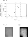
- FIG. 3 is a diagram illustrating the relation between the PTFE/Ni ratio and the anti-peeling property of the Zn-Ni alloy plating layer 3 during sliding under a high interfacial pressure of more than 1.5 GPa in terms of a Hertzian contact pressure.
- FIG. 3 was obtained based on Examples that are described later.
- the ordinate in FIG. 3 represents the number of sliding times at which the plating layer 3 peeled off in an anti-peeling property evaluation test.
- the PTFE/Ni ratio represents the PTFE/Ni ratio of the plating layer 3.
- the PTFE/Ni ratio is within a range of 0.85 or more to 1.05 or less, the anti-peeling property of the plating layer 3 during sliding under a high interfacial pressure of more than 1.5 GPa in terms of a Hertzian contact pressure is further enhanced.
- a more preferable lower limit of the PTFE/Ni ratio is 0.88, and further preferably is 0.90.
- a more preferable upper limit of the PTFE/Ni ratio is 1.03, and further preferably is 1.00.
- the composition of the plating layer 3 is measured by the following method.
- the surface of the plating layer 3 is analyzed by energy dispersive X-ray spectroscopy (EDX) using a field emission-electron probe micro analyzer (FE-EPMA).
- EDX energy dispersive X-ray spectroscopy
- FE-EPMA field emission-electron probe micro analyzer
- the analysis conditions are as follows: measurement magnification of ⁇ 1000, irradiation with an electron beam, which acceleration voltage is 15 kV and a maximum of irradiation current is 1 nA, and measurement of K ⁇ radiation intensity, and the count of nickel (Ni), the count of zinc (Zn), and the count of fluorine (F) in the visual field are measured.
- the obtained count of F is converted to the content in percent by mass of F.
- the content in percent by mass of F is divided by the atomic weight of F to convert to the molar amount of F.
- the content in mass percent of CF 2 is determined from the molar amount of F, and the determined value is defined as the content in mass percent of the PTFE 31.
- the content of the PTFE 31 in the plating layer 3 is determined.
- the obtained count of Ni is converted to the content in percent by mass of Ni.
- the obtained content of Ni is the content of Ni with respect to the entire plating layer 3. Therefore, this content of Ni is converted to the content of Ni with respect to the parent phase 30 of the plating layer 3 which does not contain the PTFE 31. By this means, the content of Ni in the parent phase 30 of the plating layer 3 is determined.
- the plating layer 3 contains impurities.
- the impurities are selected, for example, from the group consisting of hydrogen (H), oxygen (O), and Fe.
- the total of impurities contained in the plating layer 3 is, for example, less than 1.0% by mass, and more preferably is less than 0.5% by mass.
- the plating layer 3 may be a plating layer 3 that consists of the parent phase 30, the PTFE 31, and one or more impurities selected from the group consisting of hydrogen (H), oxygen (O), and Fe.
- the content of impurities may be 0% by mass.
- the plating layer 3 may be a plating layer 3 consisting of the parent phase 30 and the PTFE 31.
- the parent phase 30 of the plating layer 3 is a Zn-Ni alloy consisting of 10.0 to 17.0% by mass nickel (Ni), and the balance being zinc (Zn) and impurities.
- the parent phase 30 of the plating layer 3 includes a gamma phase.
- the parent phase 30 of the plating layer 3 may contain an eta phase.
- the parent phase 30 of the plating layer 3 may contain an alpha phase.
- the gamma phase has the highest hardness among eta phase, gamma phase, and alpha phase. Therefore, preferably the parent phase 30 of the plating layer 3 is a single-phase gamma phase.
- the crystal structure of the parent phase 30 of the plating layer 3 is identified by the following method. X-ray diffraction measurement is performed under the following measurement conditions with respect to the surface of the plating layer 3. The measured profiles that are obtained and values described in the ICDD (International Center for Diffraction Data) cards are compared to identify the phases.
- ICDD International Center for Diffraction Data
- the thickness of the plating layer 3 is not particularly limited. If the thickness of the plating layer 3 is 1.0 ⁇ m or more, durability can be consistently obtained. If the thickness of the plating layer 3 is 60.0 ⁇ m or less, the occurrence of excessive production costs can be suppressed. Therefore, the thickness of the plating layer 3 is preferably 1.0 to 60.0 ⁇ m.
- the lower limit of the thickness of the plating layer 3 is more preferably 2.0 ⁇ m, further preferably is 3.0 ⁇ m, further preferably is 5.0 ⁇ m, further preferably is 7.0 ⁇ m, and further preferably is 10.0 ⁇ m.
- the upper limit of the thickness of the plating layer 3 is more preferably 55.0 ⁇ m, further preferably is 50.0 ⁇ m, further preferably is 45.0 ⁇ m, further preferably is 40.0 ⁇ m, further preferably is 35.0 ⁇ m, further preferably is 30.0 ⁇ m, further preferably is 25.0 ⁇ m, and further preferably is 20.0 ⁇ m.
- the thickness of the plating layer 3 is measured by the following method.
- the thickness of the plating layer 3 is measured at an arbitrary four locations on the surface of the plating layer 3 using an eddy current phase-type coating thickness gauge.
- the measurement of the plating layer 3 is performed by a method in accordance with ISO (International Organization for Standardization) 21968 (2005).
- the arithmetic mean of the measurement results obtained at the four locations is defined as the thickness of the plating layer 3.
- a black irregular appearance occurs on the surface of the plating layer 3.
- "black irregular appearance” means that a part or all of the surface of the plating layer 3 has turned black.
- the present inventors considered that if the occurrence of such a black irregular appearance on the surface of the plating layer 3 can be suppressed, the appearance of the sliding member 1 will be enhanced.
- a blackened area ratio of the surface of the plating layer 3 is 30% or less.
- the plating layer 3 in the sliding member 1, even if the content of PTFE 31 in the plating layer 3 is a high content of 6.5% by mass or more, the plating layer 3 will be excellent in appearance.
- the upper limit of the blackened area ratio at the surface of the plating layer 3 is more preferably 20%, and further preferably is 15%.
- the blackened area ratio at the surface of the plating layer 3 may be 0%.
- the blackened area ratio can be measured by the following method. Specifically, a photograph is taken that included a region of 100 mm in length ⁇ 100 mm in width in which the plating layer 3 of the sliding member 1 is formed. The blackened area is identified from the obtained photograph and then the area ratio of the blackened area is measured. Note that, for those skilled in the art, it is possible to identify the blackened area. Also, by performing the image processing , the obtained photograph may be binarized and the blackened area ratio may be determined.
- the sliding member 1 includes the base material 2 and the plating layer 3 disposed on the sliding surface 20 of the base material 2.
- the sliding member 1 may include other components than the base material 2 and the plating layer 3.
- another plating layer may be formed, a chemical conversion treatment layer may be formed, or a lubricant coating layer may be formed.
- the sliding member 1 of the present embodiment can be favorably used during sliding under a high interfacial pressure of more than 1.5 GPa in terms of a Hertzian contact pressure.
- application of the sliding member 1 of the present embodiment is not limited to sliding under a high interfacial pressure of more than 1.5 GPa in terms of a Hertzian contact pressure.
- the sliding member 1 of the present embodiment can also be favorably used during sliding under an interfacial pressure of 1.5 GPa or less in terms of a Hertzian contact pressure.
- a method for producing the sliding member 1 of the present embodiment includes a preparation process and a plating layer formation process.
- the base material 2 and a plating solution are prepared.
- the base material 2 is not particularly limited as long as the base material 2 is a material that can be utilized as the sliding member 1 and can be subjected to plating.
- the plating solution contains zinc ions, nickel ions, PTFE 31, and a solvent.
- the plating solution preferably contains zinc ions: 1 to 100 g/L, nickel ions: 1 to 100 g/L, and PTFE 31: 1 to 50 g/L.
- the solvent is, for example, water.
- the plating solution may contain other components.
- the other components for example, are selected from the group consisting of a conductive auxiliary agent (supporting electrolyte) and a surface active agent.
- the conductive auxiliary agent for example, is selected from the group consisting of sodium sulfate, ammonium sulfate, and ammonium chloride.
- the surface active agent for example, is selected from the group consisting of cationic, anionic, and nonionic surface active agents.
- the plating layer 3 is formed by a plating treatment.
- the plating layer formation process at least the sliding surface 20 among the base material 2 is brought into contact with the plating solution.
- the plating layer 3 is formed on at least the sliding surface 20 of the base material 2.
- Formation of the plating layer 3 is preferably performed by electroplating.
- the electroplating is performed by bringing at least the sliding surface 20 among the base material 2 into contact with the plating solution, and passing an electric current through the plating solution.
- the electroplating conditions can be set as appropriate.
- the electroplating conditions are as follows: plating solution pH: 1 to 10, plating solution temperature: 10 to 70°C, current density: 1 to 100 A/dm 2 , and treatment time: 0.1 to 90 minutes.
- plating is performed under the following conditions.
- the blackened area ratio of the surface of the plating layer 3 can be made 30% or less.
- the aforementioned production method may include a preconditioning treatment process prior to the plating layer formation process.
- the preconditioning treatment process includes, for example, pickling and alkaline degreasing. In the preconditioning treatment process, oil or dirt adhering to the sliding surface 20 of the base material 2 is removed.
- the preconditioning treatment process may further include a grinding process such as sandblasting and finishing by mechanical grinding. Only one kind of these preconditioning treatments may be performed, or a plurality of the preconditioning treatments may be performed in combination.
- the sliding member 1 of the present embodiment is produced by the processes described above.
- the production method described above is one example of a method for producing the sliding member 1 of the present embodiment, and a method for producing the sliding member 1 is not limited to the production method described above.
- the sliding member 1 of the present embodiment may be produced by another method.
- plating layers whose compositions were varied were formed on steel sheets, and the anti-peeling property of each plating layer during sliding under a high interfacial pressure of more than 1.5 GPa in terms of a Hertzian contact pressure was evaluated. Specifically, the plating layers were formed and evaluated as follows.
- each cold-rolled steel sheet had a length of 150 mm, a width of 100 mm, and a thickness of 0.8 mm.
- the steel grade was SPCC (low-carbon steel) defined in Japanese Industrial Standard (JIS) G3141 (2021). A region of 100 mm in length ⁇ 100 mm in width on the surface of each cold-rolled steel sheet was subjected to plating.
- the plating solution was an aqueous solution having a pH of 2 to 4 containing zinc sulfate heptahydrate: 100 to 250 g/L, nickel sulfate hexahydrate: 150 to 350 g/L, sodium sulfate: 75 g/L, and polytetrafluoroethylene (PTFE): 0 to 25 g/L.
- the metallic salt concentration (total amount of Ni 2+ and Zn 2+ ) in the plating solution was 1.5 M or less.
- the composition of the plating solution was varied within the ranges described above, and a plating layer was formed on the steel sheet of each test number. By this means, the compositions of the plating layers of the respective test numbers were varied. Note that, in Test Nos.
- the plating solution did not contain PTFE, and instead contained 3 to 10 g/L of graphite.
- the plating layers were formed by electroplating.
- the plating conditions were a plating solution temperature of 50 to 60°C, a current density of 1 to 10 A/dm 2 , and the plating anode (counter electrode) of an iridium oxide-coated titanium plate.
- PTFE particles consisting of 98 % by mass or more of polytetrafluoroethylene and the balance being impurities, and having an average size within a range of 0.4 to 1.0 ⁇ m were used in the present example.
- Test Nos. 1 to 5 and 7 to 9 satisfied the following conditions.
- the composition of the plating layer of each test number was measured by the following method.
- the surface of the plating layer of each test number was analyzed by energy dispersive X-ray spectroscopy (EDX) using a field emission-electron probe micro analyzer (FE-EPMA) with the model name JXA-8530F manufactured by JEOL Ltd.
- EDX energy dispersive X-ray spectroscopy
- FE-EPMA field emission-electron probe micro analyzer
- the analysis conditions were as follows: measurement magnification: ⁇ 1000, acceleration voltage: 15 kV, irradiation current: irradiation with an electron beam reaching a maximum of 1 nA and measurement of K ⁇ radiation intensity, and the count of nickel (Ni), the count of zinc (Zn), and the count of fluorine (F) in the visual field were measured.
- the obtained count of F was converted to the content in percent by mass of F.
- the content in percent by mass of F was divided by the atomic weight of F to convert to the molar amount of F.
- the content in mass percent of CF 2 was determined from the molar amount of F, and the determined value was defined as the content in mass percent of PTFE. By this means, the content of PTFE in the plating layer was determined. The results are shown in the column "PTFE Content (mass%)" in Table 2.
- the obtained count of Ni was converted to the content in percent by mass of Ni.
- the obtained content of Ni was the content of Ni with respect to the entire plating layer. Therefore, this content of Ni was converted to the content of Ni with respect to the parent phase of the plating layer which did not contain PTFE. By this means, the content of Ni in the parent phase of the plating layer was determined. The results are shown in the column "Ni Content (mass%)" in Table 2.
- the parent phase of the plating layer of each test number was a Zn-Ni alloy consisting of Ni and the balance being Zn and impurities which is shown in Table 2.
- the crystal structure of the parent phase of the plating layer of each test number was identified by the following method. X-ray diffraction measurement was performed under the following measurement conditions with respect to the surface of the plating layer. The measured profiles that were obtained and values described in the ICDD cards were compared to identify phases. As a result it was found that in all of the Examples, the parent phase of the plating layer included a gamma phase. The parent phase of the plating layer of Test Nos. 1, 4 to 6 and 10 was a single-phase gamma phase.
- the thickness of the plating layer of each test number was measured by the following method.
- the thickness of the plating layer was measured at an arbitrary four locations on the surface of the plating layer using an eddy current phase-type coating thickness gauge with the model name PHASCOPE PM910 manufactured by Helmut Fischer GmbH.
- the measurement of the plating layer was performed by a method in accordance with ISO 21968 (2005).
- the arithmetic mean of the measurement results obtained at the four locations was defined as the thickness of the plating layer.
- the results are shown in the column "Thickness of Plating Layer ( ⁇ m)" in Table 2.
- the plating layer of the respective steel sheets that included a plating layer of each test number was subjected to an anti-peeling property evaluation test.
- the test to evaluate the anti-peeling property of the plating layer was performed under the following conditions: apparatus: Stick-Slip Tester No. 7, manufactured by Kobelco Machinery Engineering Co., Ltd.; sliding indenter: SUJ2 steel ball with diameter of 4.763 mm; load: 3 kgf (Hertzian contact pressure (average interfacial pressure): 1.56 GPa); sliding width: 10 mm; sliding speed: 4 mm/s; temperature: 1 to 30°C; lubrication: none.
- the blackened area ratio at the plating layer surface of each of Test Nos. 1 to 15 was measured by the following method.
- a photograph was taken that included the whole of a region of 100 mm in length ⁇ 100 mm in width in which the plating layer was formed.
- FIG. 4 shows the photograph of the plating layer of Test No. 10. The obtained photograph was binarized to black and white by image processing.
- FIG. 5 shows an image obtained by subjecting the photograph in FIG. 4 to black- and-white binarization. Based on the black and white binarized image, the area ratio of the black portions with respect to the entire area was determined. The results are shown in the column "Blackened Area Ratio (%)" in Table 3.
- the hardness of the plating layer of Test Nos. 3 to 5 and 15 was measured.
- the test to measure the hardness of the plating layer was performed under the following conditions.
- the Vickers hardness (Hv) of the plating layer surface was measured using a micro hardness tester with the model name FISCHERSCOPE (registered trademark) HM2000 manufactured by Helmut Fischer GmbH.
- the load was 10 to 50 mN.
- the load was adjusted so that a multiple of six times the indentation depth ( ⁇ m) was not more than the plating layer thickness.
- the results are shown in the column "Hardness of Plating Layer (Hv)" in Table 3.
- the plating layer of each of Test Nos. 1 to 10 contained a parent phase that was a Zn-Ni alloy consisting of 10.0 to 17.0% by mass Ni and the balance being Zn and impurities, and PTFE having a content of 6.5 to 21.0% by mass in the plating layer.
- the number of sliding times at the time when the plating layer peeled off was 600 times or more. It was found that the sliding members having the plating layers of Test Nos. 1 to 10 were excellent in an anti-peeling property of the plating layer during sliding under a high interfacial pressure of more than 1.5 GPa in terms of a Hertzian contact pressure.
- the blackened area ratio at the plating layer surface in Test Nos. 1 to 5 and 7 to 9 was 30% or less. It was found that, in comparison to Test No. 6 and Test No. 10, the sliding members having the plating layers of Test Nos. 1 to 5 and 7 to 9 were excellent in an anti-peeling property of the plating layer during sliding under a high interfacial pressure of more than 1.5 GPa in terms of a Hertzian contact pressure, and were also excellent in the appearance of the plating layer even when the content of PTFE in the plating layer was a high content of 6.5% or more.
- the content of PTFE was too low.
- the number of sliding times at the time when the plating layer peeled off was less than 600 times. It was found that in the sliding member having the plating layer of Test No. 11, the anti-peeling property of the plating layer during sliding under a high interfacial pressure of more than 1.5 GPa in terms of a Hertzian contact pressure was not enhanced.
- the content of Ni and content of PTFE were too low.
- the number of sliding times at the time when the plating layer peeled off was less than 600 times. It was found that in the sliding member having the plating layer of Test No. 12, the anti-peeling property of the plating layer during sliding under a high interfacial pressure of more than 1.5 GPa in terms of a Hertzian contact pressure was not enhanced.
- the content of Ni was too low.
- the number of sliding times at the time when the plating layer peeled off was less than 600 times. It was found that in the sliding member having the plating layer of Test No. 13, the anti-peeling property of the plating layer during sliding under a high interfacial pressure of more than 1.5 GPa in terms of a Hertzian contact pressure was not enhanced.
- the content of Ni was too high.
- the number of sliding times at the time when the plating layer peeled off was less than 600 times. It was found that in the sliding member having the plating layer of Test No. 14, the anti-peeling property of the plating layer during sliding under a high interfacial pressure of more than 1.5 GPa in terms of a Hertzian contact pressure was not enhanced.
- the plating layer of Test No. 15 did not contain PTFE.
- the number of sliding times at the time when the plating layer peeled off was less than 600 times. It was found that in the sliding member having the plating layer of Test No. 15, the anti-peeling property of the plating layer during sliding under a high interfacial pressure of more than 1.5 GPa in terms of a Hertzian contact pressure was not enhanced.
- the plating layers of Test Nos. 16 to 18 contained graphite instead of PTFE. As a result, in the anti-peeling property evaluation test, the number of sliding times at the time when the plating layer peeled off was less than 600 times. It was found that in the sliding members having the plating layers of Test Nos. 16 to 18, the anti-peeling property of the plating layers during sliding under a high interfacial pressure of more than 1.5 GPa in terms of a Hertzian contact pressure was not enhanced.
Landscapes
- Chemical & Material Sciences (AREA)
- Engineering & Computer Science (AREA)
- Chemical Kinetics & Catalysis (AREA)
- Electrochemistry (AREA)
- Materials Engineering (AREA)
- Metallurgy (AREA)
- Organic Chemistry (AREA)
- Electroplating Methods And Accessories (AREA)
- Sliding-Contact Bearings (AREA)
- Pistons, Piston Rings, And Cylinders (AREA)
- Manufacture Of Macromolecular Shaped Articles (AREA)
Abstract
Description
- The present disclosure relates to a sliding member.
- The term "sliding member" is a generic name for a member that is to come into contact with another member at least in one portion of the member, and the contacting portion slides. Examples of sliding members include the rails and wheels of a train, an engine cylinder and a piston, a crankshaft and a connecting rod, a tool in a drilling process, a saw blade, a pulley, a gear, an industrial screw, a nut, a bearing, a guide member, and a die. A sliding member repeatedly slides with another member.
- In some cases, a plating layer is formed on the surface of a sliding member. The plating layer is, for example, an alloy plating layer. For example,
Japanese Patent Application Publication No. 2014-228063 Japanese Patent Application Publication No. 05-279772 Japanese Patent Application Publication No. 2013-032571 - In the sliding member described in Patent Literature 1, a tin-zinc alloy layer consisting of tin and zinc is formed on a sliding surface. The thickness of the alloy plating layer is 10 to 25 µm. The sliding member described in Patent Literature 1 is characterized in that, in the alloy plating layer, a weight ratio of zinc to the total of tin and zinc is within a range of 20 to 80%. It is described in Patent Literature 1 that by this sliding member, even in a state in which there is severe sliding at a sliding portion, it is possible to suppress the amount of wear, and the sliding member can thus contribute to achieving a longer life for various machines.
- In the sliding member described in
Patent Literature 2, a sliding layer is formed of an alloy plating layer consisting of, by weight, Zn: 10 to 35%, Pb: 2 to 20%, Ni: 1 to 10%, B (boron): 0.1 to 1%, and the balance: Cu and unavoidable impurities. It is described inPatent Literature 2 that it provides a sliding member that exhibits excellent resistance to galling, wear, and corrosion, even when used under severe conditions such as an elevated operation speed and elevated temperature. -
Patent Literature 3 discloses a sliding member characterized by including a base material having a metallic surface, and a zinc alloy plating layer provided on the base material. The zinc alloy plating layer has a chemical composition containing, by mass, Ni: 2 to 8%, and Mo: 0.1 to 3%, with the balance being Zn and impurities. The hardness of the zinc alloy plating film is within a range of 150 Hv to 350 Hv, and the thickness of the zinc alloy plating layer is within a range of 0.1 to 30 µm. It is described inPatent Literature 3 that by this means a zinc alloy plating member which not only imparts excellent corrosion resistance to a base material, but can also be used as a sliding member is obtained. -
- Patent Literature 1:
Japanese Patent Application Publication No. 2014-228063 - Patent Literature 2:
Japanese Patent Application Publication No. 05-279772 - Patent Literature 3:
Japanese Patent Application Publication No. 2013-032571 - By the way, among sliding members, there are some sliding members which slide under a high interfacial pressure of more than 1.5 GPa in terms of a Hertzian contact pressure. Such sliding members are, for example, rails and wheels of a train, and industrial screws. On the other hand, a plating layer formed on a sliding member tends to peel off during sliding under a high interfacial pressure. Further, if a plating layer peels off, the galling resistance and corrosion resistance of the sliding member may decrease. Therefore, it is preferable that an anti-peeling property of the plating layer is excellent even during sliding under a high interfacial pressure of more than 1.5 GPa in terms of a Hertzian contact pressure.
- On the other hand, in Patent Literature 1 to 3, the anti-peeling property of a plating layer under a high interfacial pressure of more than 1.5 GPa in terms of a Hertzian contact pressure is not discussed. For example, in paragraph [0029] of Patent Literature 1, it is described that a sliding test is performed under an interfacial pressure of 224 MPa. For example, in paragraph [0009] of
Patent Literature 2, galling resistance at a maximum load of 500 kgf/cm2 is evaluated. This is equivalent to 0.049 GPa when converted to Pa units. InPatent Literature 3, a sliding test is not performed. Therefore, even if the techniques disclosed in Patent Literature 1 to 3 are used, there is a possibility that the anti-peeling property of a plating layer during sliding under a high interfacial pressure of more than 1.5 GPa in terms of a Hertzian contact pressure cannot be enhanced. - An objective of the present disclosure is to provide a sliding member that is excellent in an anti-peeling property of a plating layer even during sliding under a high interfacial pressure of more than 1.5 GPa in terms of a Hertzian contact pressure.
- A sliding member according to the present disclosure includes:
- a base material including a sliding surface that slides with another member, and
- a plating layer disposed on at least the sliding surface,
- wherein:
- the plating layer contains a parent phase and polytetrafluoroethylene;
- the parent phase is a Zn-Ni alloy consisting of 10.0 to 17.0% by mass Ni, and the balance being Zn and impurities; and
- a content of the polytetrafluoroethylene in the plating layer is 6.5 to 21.0% by mass.
- The sliding member according to the present disclosure is excellent in an anti-peeling property of a plating layer, even during sliding under a high interfacial pressure of more than 1.5 GPa in terms of a Hertzian contact pressure.
-
- [
FIG. 1] FIG. 1 is a cross-sectional diagram illustrating a sliding member according to the present embodiment. - [
FIG. 2] FIG. 2 is a diagram illustrating the relationship between a content of Ni in a Zn-Ni alloy plating layer, a content of polytetrafluoroethylene (PTFE) in the Zn-Ni alloy plating layer, and an anti-peeling property of the Zn-Ni alloy plating layer during sliding under a high interfacial pressure of more than 1.5 GPa in terms of a Hertzian contact pressure. - [
FIG. 3] FIG. 3 is a diagram illustrating the relation between a PTFE/Ni ratio and an anti-peeling property of a Zn-Ni alloy plating layer during sliding under a high interfacial pressure of more than 1.5 GPa in terms of a Hertzian contact pressure. - [
FIG. 4] FIG. 4 is a photograph of a plating layer of Test No. 10 of the present example. - [
FIG. 5] FIG. 5 is an image obtained by subjecting the photograph inFIG. 4 to black- and-white binarization. - The present embodiment is described in detail below with reference to the accompanying drawings. The same reference symbols are used throughout the drawings to refer to the same or like parts, and description thereof is not repeated.
- The present inventors conducted studies regarding a sliding member that is excellent in an anti-peeling property of a plating layer even during sliding under a high interfacial pressure of more than 1.5 GPa in terms of a Hertzian contact pressure. As a result, the present inventors obtained the following findings.
- If a plating layer is damaged during sliding under a high interfacial pressure of more than 1.5 GPa in terms of a Hertzian contact pressure, the plating layer will peel off from the surface of the base material. On the other hand, if the hardness of the plating layer is increased, the plating layer is not susceptible to damage during sliding. Therefore, the present inventors considered that peeling of a plating layer during sliding even under a high interfacial pressure of more than 1.5 GPa in terms of a Hertzian contact pressure can be suppressed by increasing the hardness of the plating layer.
- Meanwhile, among a plating layer, if a plating layer containing zinc (Zn) is formed, the corrosion resistance of the sliding member increases because of sacrificial protection. Therefore, conventionally, plating layers containing Zn have been used in sliding members. However, the hardness of Zn is comparatively low. It is thought that, for this reason, even if a Zn plating layer is formed, the anti-peeling property of the plating layer during sliding under a high interfacial pressure of more than 1.5 GPa in terms of a Hertzian contact pressure cannot be enhanced.
- Here, among a Zn plating layer, a Zn-Ni alloy that consists of nickel (Ni) and the balance being Zn and impurities has high hardness. Accordingly, the present inventors considered that if a plating layer is formed by a Zn-Ni alloy consisting of Ni and the balance being Zn and impurities, the anti-peeling property of the plating layer will be enhanced even during sliding under a high interfacial pressure of more than 1.5 GPa in terms of a Hertzian contact pressure. In the present description, a plating layer that consists of Ni and the balance being Zn and impurities is referred to as a "Zn-Ni alloy plating layer" or simply a "plating layer".
- It is known that the alloy phase of a Zn-Ni alloy has eta phase, gamma phase and/or alpha phase depending on the content of Ni. The eta phase is a Zn phase in which Ni is dissolved. The gamma phase is a phase of an intermetallic compound of Ni5Zn21. The alpha phase is a Ni phase in which Zn is dissolved. It is known that when the content of Ni is 10.0% by mass or less, the Zn-Ni alloy becomes a multi-phase alloy including eta phase and gamma phase. It is known that when the content of Ni is 10.0 to 17.0% by mass, the Zn-Ni alloy mainly includes gamma phase. It is known that when the content of Ni is more than 17.0% by mass, the Zn-Ni alloy becomes a multi-phase alloy including gamma phase and alpha phase. Gamma phase is the phase with the highest hardness among eta phase, gamma phase, and alpha phase. Therefore, it is conceivable that if the content of Ni in the parent phase of a Zn-Ni alloy plating layer is within the range of 10.0 to 17.0% by mass, the hardness of the Zn-Ni alloy plating layer will increase.
- The present inventors conducted further studies. As a result, the present inventors found that when a Zn-Ni alloy plating layer contains Ni in an amount within a range of 10.0 to 17.0% by mass, by containing polytetrafluoroethylene (PTFE) in an amount within a range of 6.5 to 21.0% by mass, an anti-peeling property is enhanced even under a high interfacial pressure of more than 1.5 GPa in terms of a Hertzian contact pressure.
- The present inventors conducted the following experiment. A steel sheet having a length of 150 mm, a width of 100 mm, and a thickness of 0.8 mm was prepared. A Zn-Ni alloy plating layer was formed on the surface of the steel sheet. The Zn-Ni alloy plating layer contained a parent phase and polytetrafluoroethylene (PTFE). The parent phase of the Zn-Ni alloy plating layer was a Zn-Ni alloy consisting of Ni and the balance being Zn and impurities. The anti-peeling property of the Zn-Ni alloy plating layer was evaluated while varying the content of Ni and the content of PTFE in the Zn-Ni alloy plating layer. The anti-peeling property evaluation test was performed under the following conditions. Apparatus: Stick-Slip Tester No. 7, manufactured by Kobelco Machinery Engineering Co., Ltd.; sliding indenter: SUJ2 steel ball with diameter of 4.763 mm; load: 3 kgf (Hertzian contact pressure (average interfacial pressure): 1.56 GPa; sliding width: 10 mm; sliding speed: 4 mm/s; temperature: 1 to 30°C; lubrication: none. The sliding indenter was caused to slide under the above conditions. If the Zn-Ni alloy plating layer does not peel off, because the sliding indenter and the Zn-Ni alloy plating layer slide over each other, the sliding resistance is low. If the Zn-Ni alloy plating layer peels off, because the sliding indenter and the steel sheet slide over each other, the sliding resistance rapidly increases. Therefore, the number of sliding times at the time when the sliding resistance increased to three times or more the sliding resistance of the previous sliding was defined as "number of sliding times at which the Zn-Ni alloy plating layer peeled off". The results of the anti-peeling property evaluation test are shown in
FIG. 2 . -
FIG. 2 is a diagram illustrating the relationship between the content of Ni in the Zn-Ni alloy plating layer, the content of polytetrafluoroethylene (PTFE) in the Zn-Ni alloy plating layer, and the anti-peeling property of the Zn-Ni alloy plating layer during sliding under a high interfacial pressure of more than 1.5 GPa in terms of a Hertzian contact pressure. The abscissa inFIG. 2 represents the content of Ni in the parent phase of the Zn-Ni alloy plating layer in percent by mass. The ordinate inFIG. 2 represents the content of PTFE in the Zn-Ni alloy plating layer in percent by mass. InFIG. 2 , a white circle indicates that the number of sliding times at which the Zn-Ni alloy plating layer peeled off was 600 times or more. InFIG. 2 , a black circle indicates that the number of sliding times at which the Zn-Ni alloy plating layer peeled off was less than 600 times. - Referring to
FIG. 2 , within a range in which a condition that the content of Ni was 10.0 to 17.0% by mass and a condition that the content of PTFE was 6.5 to 21.0% by mass were both satisfied, the Zn-Ni alloy plating layer did not peel off even when sliding was performed 600 times under a high interfacial pressure of more than 1.5 GPa in terms of a Hertzian contact pressure. In other words, it was found that if a condition that the content of Ni is 10.0 to 17.0% by mass and a condition that the content of PTFE is 6.5 to 21.0% by mass are both satisfied, the anti-peeling property of the Zn-Ni alloy plating layer during sliding under a high interfacial pressure of more than 1.5 GPa in terms of a Hertzian contact pressure is enhanced. - The present inventors investigated the Vickers hardness of a Zn-Ni alloy plating layer in a case where PTFE is contained in the Zn-Ni alloy plating layer. As a result, the present inventors obtained the following finding.
-
TABLE 1 Test No. Ni Content (mass%) PTFE Content (mass%) Number of Sliding Times at Which Plating Layer Peeled Off (times) Hardness of Plating Layer (Hv) 3 10.1 13.0 830 101 4 12.1 15.5 699 189 5 12.6 7.2 865 195 15 10.3 - 5 279 - Table 1 is a partial extract of results obtained in Examples to be described later. Referring to Table 1, in comparison to the Vickers hardness of the Zn-Ni alloy plating layer of Test No. 15 which did not contain PTFE, the Vickers hardness of the Zn-Ni alloy plating layer of each of Test Nos. 3 to 5 that contained PTFE was low. In addition, comparing Test No. 4 and Test No. 5 in which the contents of Ni were nearly equal, it was found that when the content of PTFE is increased, the Vickers hardness of the Zn-Ni alloy plating layer decreases. The Zn-Ni alloy plating layer of Test No. 15 which did not contain PTFE peeled off the fifth time that sliding was performed. In contrast, the Zn-Ni alloy plating layers of Test Nos. 3 to 5 which contained PTFE peeled off after sliding was performed 600 times or more. Based on the above results, the finding that, by containing PTFE, even though the hardness of the Zn-Ni alloy plating layer decreases, the anti-peeling property is enhanced was obtained, which is a completely different finding to the conventional idea.
- The reason why, when a Zn-Ni alloy plating layer contains the aforementioned content of Ni and content of PTFE, even though the hardness of the Zn-Ni alloy plating layer decreases, the anti-peeling property of the Zn-Ni alloy plating layer during sliding under a high interfacial pressure of more than 1.5 GPa in terms of a Hertzian contact pressure is enhanced is not certain. However, when a Zn-Ni alloy plating layer does not contain PTFE, the anti-peeling property during sliding under a high interfacial pressure of more than 1.5 GPa in terms of a Hertzian contact pressure is low. Therefore, it can be considered that PTFE contributes to improving the anti-peeling property during sliding under a high interfacial pressure of more than 1.5 GPa in terms of a Hertzian contact pressure. The present inventors consider that the reason is as follows. During formation of a Zn-Ni alloy plating layer, internal stress occurs in the Zn-Ni alloy plating layer. If the internal stress is high, when an external force is imparted, the Zn-Ni alloy plating layer easily peels off at the interface between the Zn-Ni alloy plating layer and the base material.
- On the other hand, there is a possibility that in the initial stage of Zn-Ni alloy plating layer formation, PTFE affects the adsorption of Zn ions to the steel sheet surface, and therefore the internal stress of the Zn-Ni alloy plating layer will decrease. Consequently, the present inventors consider that if PTFE is contained in the Zn-Ni alloy plating layer, the internal stress that occurs during formation of the Zn-Ni alloy plating layer decreases, and peeling of the Zn-Ni alloy plating layer can be suppressed.
- The sliding member of the present embodiment, which has been completed based on the above findings, is as follows.
-
- [1] A sliding member, including:
- a base material including a sliding surface that slides with another member, and
- a plating layer disposed at least on the sliding surface,
- wherein:
- the plating layer contains a parent phase and polytetrafluoroethylene,
- the parent phase is a Zn-Ni alloy consisting of 10.0 to 17.0% by mass Ni, and the balance being Zn and impurities, and
- a content of the polytetrafluoroethylene in the plating layer is 6.5 to 21.0% by mass.
- [2] The sliding member according to [1], wherein the plating layer satisfies Formula (1).

- [3] The sliding member according to [1] or [2], wherein:
a blackened area ratio of the plating layer surface is 30% or less. -
FIG. 1 is a cross-sectional diagram illustrating a sliding member 1 according to the present embodiment. Referring toFIG. 1 , the sliding member 1 includes abase material 2 and aplating layer 3. - The
base material 2 includes a slidingsurface 20 that slides with another member. The term "another member" refers to another sliding member. The sliding member 1 slides with the other sliding member at the slidingsurface 20. Note that, as described below, the slidingsurface 20 is formed at thebase material 2, and theplating layer 3 is disposed on the slidingsurface 20. Accordingly, when the sliding member 1 slides with the other sliding member, theplating layer 3 is disposed between the slidingsurface 20 and the other sliding member. - The
base material 2 is not particularly limited as long as thebase material 2 is a member that can be utilized as the sliding member 1 and can be subjected to plating. Examples of thebase material 2 include the rail and wheels of a train, an engine cylinder and a piston, a crankshaft and a connecting rod, a tool in a drilling process, a saw blade, a pulley, a gear, an industrial screw, a nut, a bearing, a guide member, and a die. The composition of thebase material 2 is not particularly limited. In other words, thebase material 2 may be made of single metal, may be made of an alloy, or may form a plating layer on the surface. Thebase material 2 is, for example, carbon steel, stainless steel, alloy steel, carbon steel with a plating layer, stainless steel with a plating layer, alloy steel with a plating layer or the like. - The
plating layer 3 is disposed on at least the slidingsurface 20. In a case where thebase material 2 includes another surface other than the slidingsurface 20, theplating layer 3 may be disposed only on the slidingsurface 20, or may be disposed on the other surface in addition to the slidingsurface 20. - The
plating layer 3 contains aparent phase 30 and polytetrafluoroethylene (PTFE) 31. - The
parent phase 30 of theplating layer 3 is a Zn-Ni alloy consisting of 10.0 to 17.0% by mass nickel (Ni), and the balance being zinc (Zn) and impurities. In other words, theparent phase 30 is a Zn-Ni alloy consisting of 10.0 to 17.0% by mass Ni, 83.0 to 90.0% by mass Zn, and impurities. It is known that a Zn-Ni alloy having this composition mainly includes a gamma phase. In this case, the hardness of the Zn-Ni alloy plating layer increases, and an anti-peeling property of theplating layer 3 is enhanced even during sliding under a high interfacial pressure of more than 1.5 GPa in terms of a Hertzian contact pressure. A preferable lower limit of the content of Ni in theparent phase 30 of theplating layer 3 is 10.3% by mass, more preferably is 10.5% by mass, further preferably is 10.8% by mass, and further preferably is 11.0% by mass. A preferable upper limit of the content of Ni in theparent phase 30 of theplating layer 3 is 16.5% by mass, more preferably is 16.0% by mass, further preferably is 15.0% by mass, and further preferably is 14.0% by mass. Examples of the impurities include hydrogen (H), oxygen (O), and iron (Fe). In some cases, theparent phase 30 of theplating layer 3 may contain impurities in a total amount of 1.0% by mass or less. Note that, the term "content of Ni" refers to the content of Ni in theparent phase 30. - The polytetrafluoroethylene (PTFE) 31 is a resin having repeating units of (C2F4)n. In the present description,
PTFE 31 means particles which contains polytetrafluoroethylene as a main component. Specifically,PTFE 31 consists of 98% by mass or more of polytetrafluoroethylene, and the balance being impurities. That is,PTFE 31 contained in theplating layer 3 corresponds to particles of polytetrafluoroethylene. ThePTFE 31 according to the present embodiment is not particularly limited, and well-known particles of polytetrafluoroethylene can be used. Note that, the size ofPTFE 31 is not particularly limited, for example, the particle size ofPTFE 31 may be within a range of 0.1 to 2.0 µm, or may be within a range of 0.4 to 1.0 µm. Also, the particle size ofPTFE 31 means the average particle size ofPTFE 31. - In the present embodiment, the content of the
PTFE 31 in theplating layer 3 is 6.5 to 21.0% by mass. If theplating layer 3 contains theparent phase 30 that is a Zn-Ni alloy consisting of 10.0 to 17.0% by mass Ni and the balance being Zn and impurities, and 6.5 to 21.0% by mass thePTFE 31, an anti-peeling property will be enhanced even during sliding under a high interfacial pressure of more than 1.5 GPa in terms of a Hertzian contact pressure. A preferable lower limit of the content of thePTFE 31 is 6.7% by mass, more preferably is 6.9% by mass, further preferably is 7.0% by mass, further preferably is 7.5% by mass, and further preferably is 8.0% by mass. A preferable upper limit of the content of thePTFE 31 is 20.5% by mass, more preferably is 20.0% by mass, further preferably is 19.5% by mass, further preferably is 19.0% by mass, further preferably is 18.5% by mass, further preferably is 18.0% by mass, further preferably is 17.5% by mass, and further preferably is 17.0% by mass. Note that, the term "content of PTFE" refers to the content of PTFE in theplating layer 3. - A ratio between the content of PTFE in the
plating layer 3 and the content of Ni in theparent phase 30 is not particularly limited. However, preferably the ratio satisfies Formula (1).
- Where, in Formula (1), the content in percent by mass of the
PTFE 31 in theplating layer 3 is substituted for [PTFE], and the content in percent by mass of Ni in theparent phase 30 is substituted for [Ni]. - Hereunder, the ratio of the content in percent by mass of the
PTFE 31 in theplating layer 3 to the content in percent by mass of Ni in theparent phase 30 is referred to as "PTFE/Ni ratio".FIG. 3 is a diagram illustrating the relation between the PTFE/Ni ratio and the anti-peeling property of the Zn-Nialloy plating layer 3 during sliding under a high interfacial pressure of more than 1.5 GPa in terms of a Hertzian contact pressure.FIG. 3 was obtained based on Examples that are described later. The ordinate inFIG. 3 represents the number of sliding times at which theplating layer 3 peeled off in an anti-peeling property evaluation test. The abscissa inFIG. 3 represents the PTFE/Ni ratio of theplating layer 3. Referring toFIG. 3 , if the PTFE/Ni ratio is within a range of 0.85 or more to 1.05 or less, the anti-peeling property of theplating layer 3 during sliding under a high interfacial pressure of more than 1.5 GPa in terms of a Hertzian contact pressure is further enhanced. A more preferable lower limit of the PTFE/Ni ratio is 0.88, and further preferably is 0.90. A more preferable upper limit of the PTFE/Ni ratio is 1.03, and further preferably is 1.00. - The composition of the
plating layer 3 is measured by the following method. The surface of theplating layer 3 is analyzed by energy dispersive X-ray spectroscopy (EDX) using a field emission-electron probe micro analyzer (FE-EPMA). Specifically, the analysis conditions are as follows: measurement magnification of ×1000, irradiation with an electron beam, which acceleration voltage is 15 kV and a maximum of irradiation current is 1 nA, and measurement of Kα radiation intensity, and the count of nickel (Ni), the count of zinc (Zn), and the count of fluorine (F) in the visual field are measured. The obtained count of F is converted to the content in percent by mass of F. The content in percent by mass of F is divided by the atomic weight of F to convert to the molar amount of F. The content in mass percent of CF2 is determined from the molar amount of F, and the determined value is defined as the content in mass percent of thePTFE 31. By this means, the content of thePTFE 31 in theplating layer 3 is determined. The obtained count of Ni is converted to the content in percent by mass of Ni. The obtained content of Ni is the content of Ni with respect to theentire plating layer 3. Therefore, this content of Ni is converted to the content of Ni with respect to theparent phase 30 of theplating layer 3 which does not contain thePTFE 31. By this means, the content of Ni in theparent phase 30 of theplating layer 3 is determined. - In some cases the
plating layer 3 contains impurities. The impurities are selected, for example, from the group consisting of hydrogen (H), oxygen (O), and Fe. The total of impurities contained in theplating layer 3 is, for example, less than 1.0% by mass, and more preferably is less than 0.5% by mass. Accordingly, theplating layer 3 may be aplating layer 3 that consists of theparent phase 30, thePTFE 31, and one or more impurities selected from the group consisting of hydrogen (H), oxygen (O), and Fe. The content of impurities may be 0% by mass. Accordingly, theplating layer 3 may be aplating layer 3 consisting of theparent phase 30 and thePTFE 31. - The
parent phase 30 of theplating layer 3 is a Zn-Ni alloy consisting of 10.0 to 17.0% by mass nickel (Ni), and the balance being zinc (Zn) and impurities. In this case, theparent phase 30 of theplating layer 3 includes a gamma phase. The gamma phase is a phase having a cubic crystal structure with a lattice constant α = 0.890 nm that has the chemical formula Ni5Zn21. Theparent phase 30 of theplating layer 3 may contain an eta phase. The eta phase is a phase having a hexagonal crystal structure with lattice constants a = 0.267 nm and c = 0.495 nm that has the chemical formula Zn. Theparent phase 30 of theplating layer 3 may contain an alpha phase. The alpha phase is a phase having a face-centered cubic crystal structure with a lattice constant a = 0.352 nm that has the chemical formula Ni. The gamma phase has the highest hardness among eta phase, gamma phase, and alpha phase. Therefore, preferably theparent phase 30 of theplating layer 3 is a single-phase gamma phase. - The crystal structure of the
parent phase 30 of theplating layer 3 is identified by the following method. X-ray diffraction measurement is performed under the following measurement conditions with respect to the surface of theplating layer 3. The measured profiles that are obtained and values described in the ICDD (International Center for Diffraction Data) cards are compared to identify the phases. - Apparatus: X-ray diffractometer
- X-ray tube: Co-Kα radiation
- Scan range: 2θ = 10 to 110°
- Scan step: 0.02°
- The thickness of the
plating layer 3 is not particularly limited. If the thickness of theplating layer 3 is 1.0 µm or more, durability can be consistently obtained. If the thickness of theplating layer 3 is 60.0 µm or less, the occurrence of excessive production costs can be suppressed. Therefore, the thickness of theplating layer 3 is preferably 1.0 to 60.0 µm. The lower limit of the thickness of theplating layer 3 is more preferably 2.0 µm, further preferably is 3.0 µm, further preferably is 5.0 µm, further preferably is 7.0 µm, and further preferably is 10.0 µm. The upper limit of the thickness of theplating layer 3 is more preferably 55.0 µm, further preferably is 50.0 µm, further preferably is 45.0 µm, further preferably is 40.0 µm, further preferably is 35.0 µm, further preferably is 30.0 µm, further preferably is 25.0 µm, and further preferably is 20.0 µm. - The thickness of the
plating layer 3 is measured by the following method. The thickness of theplating layer 3 is measured at an arbitrary four locations on the surface of theplating layer 3 using an eddy current phase-type coating thickness gauge. The measurement of theplating layer 3 is performed by a method in accordance with ISO (International Organization for Standardization) 21968 (2005). The arithmetic mean of the measurement results obtained at the four locations is defined as the thickness of theplating layer 3. - As a result of studies conducted by the present inventors it was found that when
PTFE 31 is contained in a large amount of 6.5% by mass or more in theplating layer 3 that is a Zn-Ni alloy, a black irregular appearance occurs on the surface of theplating layer 3. In the present description, "black irregular appearance" means that a part or all of the surface of theplating layer 3 has turned black. The present inventors considered that if the occurrence of such a black irregular appearance on the surface of theplating layer 3 can be suppressed, the appearance of the sliding member 1 will be enhanced. In the sliding member 1 of the present embodiment, preferably a blackened area ratio of the surface of theplating layer 3 is 30% or less. In this case, in the sliding member 1, even if the content ofPTFE 31 in theplating layer 3 is a high content of 6.5% by mass or more, theplating layer 3 will be excellent in appearance. The upper limit of the blackened area ratio at the surface of theplating layer 3 is more preferably 20%, and further preferably is 15%. The blackened area ratio at the surface of theplating layer 3 may be 0%. - In the present embodiment, the blackened area ratio can be measured by the following method. Specifically, a photograph is taken that included a region of 100 mm in length × 100 mm in width in which the
plating layer 3 of the sliding member 1 is formed. The blackened area is identified from the obtained photograph and then the area ratio of the blackened area is measured. Note that, for those skilled in the art, it is possible to identify the blackened area. Also, by performing the image processing , the obtained photograph may be binarized and the blackened area ratio may be determined. - As described above, the sliding member 1 according to the present embodiment includes the
base material 2 and theplating layer 3 disposed on the slidingsurface 20 of thebase material 2. Here, the sliding member 1 may include other components than thebase material 2 and theplating layer 3. For example, as an upper layer of theplating layer 3 of the sliding member 1, another plating layer may be formed, a chemical conversion treatment layer may be formed, or a lubricant coating layer may be formed. - The sliding member 1 of the present embodiment can be favorably used during sliding under a high interfacial pressure of more than 1.5 GPa in terms of a Hertzian contact pressure. However, application of the sliding member 1 of the present embodiment is not limited to sliding under a high interfacial pressure of more than 1.5 GPa in terms of a Hertzian contact pressure. The sliding member 1 of the present embodiment can also be favorably used during sliding under an interfacial pressure of 1.5 GPa or less in terms of a Hertzian contact pressure.
- A method for producing the sliding member 1 of the present embodiment includes a preparation process and a plating layer formation process.
- In the preparation process, the
base material 2 and a plating solution are prepared. As mentioned above, thebase material 2 is not particularly limited as long as thebase material 2 is a material that can be utilized as the sliding member 1 and can be subjected to plating. The plating solution contains zinc ions, nickel ions,PTFE 31, and a solvent. The plating solution preferably contains zinc ions: 1 to 100 g/L, nickel ions: 1 to 100 g/L, and PTFE 31: 1 to 50 g/L. The solvent is, for example, water. The plating solution may contain other components. The other components, for example, are selected from the group consisting of a conductive auxiliary agent (supporting electrolyte) and a surface active agent. The conductive auxiliary agent, for example, is selected from the group consisting of sodium sulfate, ammonium sulfate, and ammonium chloride. The surface active agent, for example, is selected from the group consisting of cationic, anionic, and nonionic surface active agents. - In the plating layer formation process, the
plating layer 3 is formed by a plating treatment. In the plating layer formation process, at least the slidingsurface 20 among thebase material 2 is brought into contact with the plating solution. By this means, theplating layer 3 is formed on at least the slidingsurface 20 of thebase material 2. Formation of theplating layer 3 is preferably performed by electroplating. The electroplating is performed by bringing at least the slidingsurface 20 among thebase material 2 into contact with the plating solution, and passing an electric current through the plating solution. The electroplating conditions can be set as appropriate. For example, the electroplating conditions are as follows: plating solution pH: 1 to 10, plating solution temperature: 10 to 70°C, current density: 1 to 100 A/dm2, and treatment time: 0.1 to 90 minutes. - In the case of suppressing the occurrence of a black irregular appearance on the surface of the
plating layer 3, for example, plating is performed under the following conditions. In this case, the blackened area ratio of the surface of theplating layer 3 can be made 30% or less. - Ni2+/Zn2+ molar ratio in plating solution ≤ 1.5
- metallic salt concentration (total of Ni2+ and Zn2+) in plating solution ≤ 1.5 M
- PTFE concentration in plating solution ≤ 25 g/L
- plating solution temperature: 57 to 65°C
- plating solution pH: 2 to 4
- plating solution flow rate (linear flow rate): 0.1 to 0.4 m/sec
- current density: ≤ 3 A/dm2
- As necessary, the aforementioned production method may include a preconditioning treatment process prior to the plating layer formation process. The preconditioning treatment process includes, for example, pickling and alkaline degreasing. In the preconditioning treatment process, oil or dirt adhering to the sliding
surface 20 of thebase material 2 is removed. The preconditioning treatment process may further include a grinding process such as sandblasting and finishing by mechanical grinding. Only one kind of these preconditioning treatments may be performed, or a plurality of the preconditioning treatments may be performed in combination. - The sliding member 1 of the present embodiment is produced by the processes described above. However, the production method described above is one example of a method for producing the sliding member 1 of the present embodiment, and a method for producing the sliding member 1 is not limited to the production method described above. The sliding member 1 of the present embodiment may be produced by another method.
- Hereunder, advantageous effects of the sliding member of the present embodiment will be described more specifically by way of examples. The conditions adopted in the following examples are one example of conditions which are employed for confirming the feasibility and advantageous effects of the sliding member of the present embodiment. Accordingly, the sliding member of the present embodiment is not limited to this one example of the conditions.
- In the Examples, plating layers whose compositions were varied were formed on steel sheets, and the anti-peeling property of each plating layer during sliding under a high interfacial pressure of more than 1.5 GPa in terms of a Hertzian contact pressure was evaluated. Specifically, the plating layers were formed and evaluated as follows.
- In the present examples, commercially available cold-rolled steel sheets were used based on the assumption of use as a base material. Each cold-rolled steel sheet had a length of 150 mm, a width of 100 mm, and a thickness of 0.8 mm. The steel grade was SPCC (low-carbon steel) defined in Japanese Industrial Standard (JIS) G3141 (2021). A region of 100 mm in length × 100 mm in width on the surface of each cold-rolled steel sheet was subjected to plating.
- The plating solution was an aqueous solution having a pH of 2 to 4 containing zinc sulfate heptahydrate: 100 to 250 g/L, nickel sulfate hexahydrate: 150 to 350 g/L, sodium sulfate: 75 g/L, and polytetrafluoroethylene (PTFE): 0 to 25 g/L. The metallic salt concentration (total amount of Ni2+ and Zn2+) in the plating solution was 1.5 M or less. The composition of the plating solution was varied within the ranges described above, and a plating layer was formed on the steel sheet of each test number. By this means, the compositions of the plating layers of the respective test numbers were varied. Note that, in Test Nos. 16 to 18, the plating solution did not contain PTFE, and instead contained 3 to 10 g/L of graphite. The plating layers were formed by electroplating. The plating conditions were a plating solution temperature of 50 to 60°C, a current density of 1 to 10 A/dm2, and the plating anode (counter electrode) of an iridium oxide-coated titanium plate. As PTFE, particles consisting of 98 % by mass or more of polytetrafluoroethylene and the balance being impurities, and having an average size within a range of 0.4 to 1.0 µm were used in the present example.
- In addition to the aforementioned conditions, Test Nos. 1 to 5 and 7 to 9 satisfied the following conditions.
- Ni2+/Zn2+ molar ratio in plating solution ≤ 1.5
- plating solution temperature: 57 to 60°C
- plating solution flow rate (linear flow rate): 0.1 to 0.4 m/sec
- current density: ≤ 3 A/dm2
- In Test No. 6, plating was performed under the following conditions.
- Ni2+/Zn2+ molar ratio in plating solution = 3.0
- plating solution temperature: 50°C
- plating solution flow rate (linear flow rate): 0 m/sec
- current density: ≤ 3 A/dm2
- In Test No. 10, plating was performed under the following conditions.
- Ni2+/Zn2+ molar ratio in plating solution = 3.0
- plating solution temperature: 57 to 60°C
- plating solution flow rate (linear flow rate): 0.5 m/sec
- current density: 6 A/dm2
- The composition of the plating layer of each test number was measured by the following method. The surface of the plating layer of each test number was analyzed by energy dispersive X-ray spectroscopy (EDX) using a field emission-electron probe micro analyzer (FE-EPMA) with the model name JXA-8530F manufactured by JEOL Ltd. Specifically, the analysis conditions were as follows: measurement magnification: ×1000, acceleration voltage: 15 kV, irradiation current: irradiation with an electron beam reaching a maximum of 1 nA and measurement of Kα radiation intensity, and the count of nickel (Ni), the count of zinc (Zn), and the count of fluorine (F) in the visual field were measured. The obtained count of F was converted to the content in percent by mass of F. The content in percent by mass of F was divided by the atomic weight of F to convert to the molar amount of F. The content in mass percent of CF2 was determined from the molar amount of F, and the determined value was defined as the content in mass percent of PTFE. By this means, the content of PTFE in the plating layer was determined. The results are shown in the column "PTFE Content (mass%)" in Table 2.
- The obtained count of Ni was converted to the content in percent by mass of Ni. The obtained content of Ni was the content of Ni with respect to the entire plating layer. Therefore, this content of Ni was converted to the content of Ni with respect to the parent phase of the plating layer which did not contain PTFE. By this means, the content of Ni in the parent phase of the plating layer was determined. The results are shown in the column "Ni Content (mass%)" in Table 2. The parent phase of the plating layer of each test number was a Zn-Ni alloy consisting of Ni and the balance being Zn and impurities which is shown in Table 2. In Table 2, the ratio of the content in percent by mass of PTFE in the plating layer to the content in percent by mass of Ni in the parent phase is shown in the column "[PTFE]/[Ni]". Note that, in Test No. 15, the plating layer did not contain PTFE. In Test Nos. 16 to 18, the plating layer did not contain PTFE, and instead contained graphite. With regard to Test Nos. 16 to 18, the content of graphite is shown in the column "PTFE Content (mass%)" in Table 2.
-
TABLE 2 Test No. Ni Content (mass%) PTFE Content (mass%) [PTFE]/[Ni] Thickness of Plating Layer (µm) 1 13.9 11.3 0.81 11.2 2 16.6 10.1 0.61 11.1 3 10.1 13.0 1.29 10.0 4 12.1 15.5 1.28 10.0 5 12.6 7.2 0.57 11.7 6 14.3 16.6 1.16 10.0 7 11.8 11.2 0.95 12.1 8 10.6 10.3 0.97 12.0 9 11.9 11.0 0.92 12.0 10 15.8 13.1 0.83 12.0 11 12.4 6.2 0.50 10.8 12 7.2 4.7 0.66 11.5 13 7.5 12.4 1.65 11.8 14 48.5 10.1 0.21 10.0 15 10.3 - - 10.8 16 14.8 (Graphite) 6.7 - 10.2 17 10.7 (Graphite) 8.9 - 16.4 18 13.7 (Graphite) 9.6 - 10.2 - The crystal structure of the parent phase of the plating layer of each test number was identified by the following method. X-ray diffraction measurement was performed under the following measurement conditions with respect to the surface of the plating layer. The measured profiles that were obtained and values described in the ICDD cards were compared to identify phases. As a result it was found that in all of the Examples, the parent phase of the plating layer included a gamma phase. The parent phase of the plating layer of Test Nos. 1, 4 to 6 and 10 was a single-phase gamma phase.
- Apparatus: X-ray diffractometer RINT-2500 manufactured by Rigaku Corporation
- X-ray tube: Co-Kα radiation
- Scan range: 2θ = 10 to 110°
- Scan step: 0.02°
- The thickness of the plating layer of each test number was measured by the following method. The thickness of the plating layer was measured at an arbitrary four locations on the surface of the plating layer using an eddy current phase-type coating thickness gauge with the model name PHASCOPE PM910 manufactured by Helmut Fischer GmbH. The measurement of the plating layer was performed by a method in accordance with ISO 21968 (2005). The arithmetic mean of the measurement results obtained at the four locations was defined as the thickness of the plating layer. The results are shown in the column "Thickness of Plating Layer (µm)" in Table 2.
- The plating layer of the respective steel sheets that included a plating layer of each test number was subjected to an anti-peeling property evaluation test. The test to evaluate the anti-peeling property of the plating layer was performed under the following conditions: apparatus: Stick-Slip Tester No. 7, manufactured by Kobelco Machinery Engineering Co., Ltd.; sliding indenter: SUJ2 steel ball with diameter of 4.763 mm; load: 3 kgf (Hertzian contact pressure (average interfacial pressure): 1.56 GPa); sliding width: 10 mm; sliding speed: 4 mm/s; temperature: 1 to 30°C; lubrication: none. The number of sliding times at the time when the sliding resistance increased to three times or more the sliding resistance of the previous sliding was defined as the "number of sliding times at which the plating layer peeled off". The results are shown in the column "Number of Sliding Times at Time Plating Layer Peeled Off (times)" in Table 3.
-
TABLE 3 Test No. Number of Sliding Times at Which Plating Layer Peeled Off (times) Blackened Area Ratio (%) Hardness of Plating Layer (Hv) 1 1307 5 - 2 690 10 - 3 830 3 101 4 699 10 189 5 865 0 195 6 608 80 - 7 2583 0 - 8 2244 0 - 9 2440 0 - 10 774 90 - 11 185 50 - 12 24 0 - 13 77 5 - 14 130 75 - 15 5 0 279 16 <600 - - 17 <600 - - 18 <600 - - - The blackened area ratio at the plating layer surface of each of Test Nos. 1 to 15 was measured by the following method. A photograph was taken that included the whole of a region of 100 mm in length × 100 mm in width in which the plating layer was formed.
FIG. 4 shows the photograph of the plating layer of Test No. 10. The obtained photograph was binarized to black and white by image processing.FIG. 5 shows an image obtained by subjecting the photograph inFIG. 4 to black- and-white binarization. Based on the black and white binarized image, the area ratio of the black portions with respect to the entire area was determined. The results are shown in the column "Blackened Area Ratio (%)" in Table 3. - The hardness of the plating layer of Test Nos. 3 to 5 and 15 was measured. The test to measure the hardness of the plating layer was performed under the following conditions. The Vickers hardness (Hv) of the plating layer surface was measured using a micro hardness tester with the model name FISCHERSCOPE (registered trademark) HM2000 manufactured by Helmut Fischer GmbH. The load was 10 to 50 mN. The load was adjusted so that a multiple of six times the indentation depth (µm) was not more than the plating layer thickness. The results are shown in the column "Hardness of Plating Layer (Hv)" in Table 3.
- Referring to Tables 2 and 3, the plating layer of each of Test Nos. 1 to 10 contained a parent phase that was a Zn-Ni alloy consisting of 10.0 to 17.0% by mass Ni and the balance being Zn and impurities, and PTFE having a content of 6.5 to 21.0% by mass in the plating layer. As a result, in the anti-peeling property evaluation test, the number of sliding times at the time when the plating layer peeled off was 600 times or more. It was found that the sliding members having the plating layers of Test Nos. 1 to 10 were excellent in an anti-peeling property of the plating layer during sliding under a high interfacial pressure of more than 1.5 GPa in terms of a Hertzian contact pressure.
- In addition, in Test Nos. 7 to 9 in which the PTFE/Ni ratio was in the range of 0.85 or more to 1.05 or less, in the anti-peeling property evaluation test, the number of sliding times at the time when the plating layer peeled off was 2000 times or more. It was found that in comparison to Test Nos. 1 to 6 and 10, the sliding members having the plating layers of Test Nos. 7 to 9 were more excellent in an anti-peeling property of the plating layer during sliding under a high interfacial pressure of more than 1.5 GPa in terms of a Hertzian contact pressure.
- The blackened area ratio at the plating layer surface in Test Nos. 1 to 5 and 7 to 9 was 30% or less. It was found that, in comparison to Test No. 6 and Test No. 10, the sliding members having the plating layers of Test Nos. 1 to 5 and 7 to 9 were excellent in an anti-peeling property of the plating layer during sliding under a high interfacial pressure of more than 1.5 GPa in terms of a Hertzian contact pressure, and were also excellent in the appearance of the plating layer even when the content of PTFE in the plating layer was a high content of 6.5% or more.
- On the other hand, in the plating layer of Test No. 11, the content of PTFE was too low. As a result, in the anti-peeling property evaluation test, the number of sliding times at the time when the plating layer peeled off was less than 600 times. It was found that in the sliding member having the plating layer of Test No. 11, the anti-peeling property of the plating layer during sliding under a high interfacial pressure of more than 1.5 GPa in terms of a Hertzian contact pressure was not enhanced.
- In the plating layer of Test No. 12, the content of Ni and content of PTFE were too low. As a result, in the anti-peeling property evaluation test, the number of sliding times at the time when the plating layer peeled off was less than 600 times. It was found that in the sliding member having the plating layer of Test No. 12, the anti-peeling property of the plating layer during sliding under a high interfacial pressure of more than 1.5 GPa in terms of a Hertzian contact pressure was not enhanced.
- In the plating layer of Test No. 13, the content of Ni was too low. As a result, in the anti-peeling property evaluation test, the number of sliding times at the time when the plating layer peeled off was less than 600 times. It was found that in the sliding member having the plating layer of Test No. 13, the anti-peeling property of the plating layer during sliding under a high interfacial pressure of more than 1.5 GPa in terms of a Hertzian contact pressure was not enhanced.
- In the plating layer of Test No. 14, the content of Ni was too high. As a result, in the anti-peeling property evaluation test, the number of sliding times at the time when the plating layer peeled off was less than 600 times. It was found that in the sliding member having the plating layer of Test No. 14, the anti-peeling property of the plating layer during sliding under a high interfacial pressure of more than 1.5 GPa in terms of a Hertzian contact pressure was not enhanced.
- The plating layer of Test No. 15 did not contain PTFE. As a result, in the anti-peeling property evaluation test, the number of sliding times at the time when the plating layer peeled off was less than 600 times. It was found that in the sliding member having the plating layer of Test No. 15, the anti-peeling property of the plating layer during sliding under a high interfacial pressure of more than 1.5 GPa in terms of a Hertzian contact pressure was not enhanced.
- The plating layers of Test Nos. 16 to 18 contained graphite instead of PTFE. As a result, in the anti-peeling property evaluation test, the number of sliding times at the time when the plating layer peeled off was less than 600 times. It was found that in the sliding members having the plating layers of Test Nos. 16 to 18, the anti-peeling property of the plating layers during sliding under a high interfacial pressure of more than 1.5 GPa in terms of a Hertzian contact pressure was not enhanced.
- An embodiment of the present invention has been described above. However, the embodiment described above is merely an example for carrying out the present invention. Therefore, the present invention is not limited to the above-described embodiment, and can be practiced by appropriately modifying the above-described embodiment within a range not departing from the spirit thereof.
-
- 1
- Sliding Member
- 2
- Base Material
- 3
- Plating Layer
- 20
- Sliding Surface
- 30
- Parent Phase
- 31
- Polytetrafluoroethylene (PTFE)
Claims (3)
- A sliding member, comprising:a base material including a sliding surface that slides with another member, anda plating layer disposed at least on the sliding surface,wherein:the plating layer contains a parent phase and polytetrafluoroethylene,the parent phase is a Zn-Ni alloy consisting of 10.0 to 17.0% by mass Ni, and the balance being Zn and impurities, anda content of the polytetrafluoroethylene in the plating layer is 6.5 to 21.0% by mass.
- The sliding member according to claim 1, wherein:the plating layer satisfies Formula (1):
 where, in Formula (1), a content in percent by mass of the polytetrafluoroethylene in the plating layer is substituted for [PTFE], and a content in percent by mass of the Ni in the parent phase is substituted for [Ni].
 - The sliding member according to claim 1 or claim 2, wherein:
a blackened area ratio of the plating layer surface is 30% or less.
Applications Claiming Priority (2)
| Application Number | Priority Date | Filing Date | Title |
|---|---|---|---|
| JP2022111820 | 2022-07-12 | ||
| PCT/JP2023/025551 WO2024014450A1 (en) | 2022-07-12 | 2023-07-11 | Sliding member |
Publications (2)
| Publication Number | Publication Date |
|---|---|
| EP4556599A1 true EP4556599A1 (en) | 2025-05-21 |
| EP4556599A4 EP4556599A4 (en) | 2026-01-21 |
Family
ID=89536734
Family Applications (1)
| Application Number | Title | Priority Date | Filing Date |
|---|---|---|---|
| EP23839622.0A Pending EP4556599A4 (en) | 2022-07-12 | 2023-07-11 | SLIDING ELEMENT |
Country Status (7)
| Country | Link |
|---|---|
| EP (1) | EP4556599A4 (en) |
| JP (1) | JP7791488B2 (en) |
| CN (1) | CN119768567A (en) |
| AR (1) | AR129871A1 (en) |
| AU (1) | AU2023305259A1 (en) |
| MX (1) | MX2024016050A (en) |
| WO (1) | WO2024014450A1 (en) |
Family Cites Families (10)
| Publication number | Priority date | Publication date | Assignee | Title |
|---|---|---|---|---|
| JPH08941B2 (en) | 1992-03-31 | 1996-01-10 | 大同メタル工業株式会社 | Abrasion resistant sliding alloy, sliding member and manufacturing method thereof |
| JPH0849090A (en) * | 1994-08-05 | 1996-02-20 | Nippon Steel Corp | Surface-treated steel sheet for fuel tanks with excellent corrosion resistance and workability |
| JP4681161B2 (en) | 2000-07-14 | 2011-05-11 | 大阪瓦斯株式会社 | Plating film and plating coating using the same |
| FR2839729B1 (en) * | 2002-05-16 | 2005-02-11 | Univ Toulouse | METHOD FOR PROTECTING AN ALUMINUM STEEL OR ALLOY SUBSTRATE AGAINST CORROSION ENABLING IT TO PROVIDE TRIBOLOGICAL PROPERTIES, AND SUBSTRATE OBTAINED |
| JP2010266028A (en) * | 2009-05-15 | 2010-11-25 | Nippon Steel Corp | Drilling tapping screw |
| JP5223061B2 (en) | 2011-08-02 | 2013-06-26 | ユケン工業株式会社 | Sliding member made of zinc alloy plating member and electrolytic zinc alloy plating solution |
| JP6386214B2 (en) | 2013-05-22 | 2018-09-05 | Ntn株式会社 | Cage for rolling bearing, and rolling bearing |
| JP6278652B2 (en) * | 2013-10-02 | 2018-02-14 | 株式会社シマノ | Sliding member, bicycle component using sliding member, fishing tackle component using sliding member, and manufacturing method of sliding member |
| JP6343514B2 (en) * | 2014-07-31 | 2018-06-13 | 住友理工株式会社 | Manufacturing method of molding die and molding die |
| KR101908815B1 (en) * | 2016-12-23 | 2018-10-16 | 주식회사 포스코 | ELECTROPLATED Zn-Ni BASED STEEL SHEET HAVING EXCELLENT CORROSION RESISTANCE AND WORKABILITY AND METHOD OF MANUFACTURING THE SAME |
-
2023
- 2023-07-07 AR ARP230101786A patent/AR129871A1/en unknown
- 2023-07-11 EP EP23839622.0A patent/EP4556599A4/en active Pending
- 2023-07-11 CN CN202380052288.4A patent/CN119768567A/en active Pending
- 2023-07-11 AU AU2023305259A patent/AU2023305259A1/en active Pending
- 2023-07-11 WO PCT/JP2023/025551 patent/WO2024014450A1/en not_active Ceased
- 2023-07-11 JP JP2024533720A patent/JP7791488B2/en active Active
-
2024
- 2024-12-18 MX MX2024016050A patent/MX2024016050A/en unknown
Also Published As
| Publication number | Publication date |
|---|---|
| JP7791488B2 (en) | 2025-12-24 |
| CN119768567A (en) | 2025-04-04 |
| EP4556599A4 (en) | 2026-01-21 |
| JPWO2024014450A1 (en) | 2024-01-18 |
| WO2024014450A1 (en) | 2024-01-18 |
| MX2024016050A (en) | 2025-04-02 |
| AR129871A1 (en) | 2024-10-09 |
| AU2023305259A1 (en) | 2025-01-16 |
Similar Documents
| Publication | Publication Date | Title |
|---|---|---|
| Zhong et al. | Nickel–tungsten alloy brush plating for engineering applications | |
| Nazir et al. | Synergistic wear-corrosion analysis and modelling of nanocomposite coatings | |
| Wu et al. | Effect of frictional frequency on the subsurface evolution of 316L stainless steel in tribocorrosion and its influence on the synergistic effect between corrosion and wear | |
| EP3680534A1 (en) | Pipe threaded joint, and method for producing pipe threaded joint | |
| Liu et al. | Electrodeposition of nanocrystalline Ni and NiCr alloy coatings: Effects of Cr content on microhardness and wear resistance improvement | |
| Yang et al. | Research on the synergistic damage behavior of tribocorrosion of CoCrFeNi-X (Ti, Mn, Mo, Al) high-entropy alloys | |
| Chauhan et al. | Enhancement of wear resistance in electrodeposited Ni-Ag self-lubricated alloy coatings via in-situ formation of solid lubricating phases for high-temperature tribological applications | |
| Tafreshi et al. | Effect of PTFE on characteristics, corrosion, and tribological behavior of Zn–Ni electrodeposits | |
| Alkan | Enhancement of marine corrosion and tribocorrosion resistance of offshore mooring chain steel by aluminizing process | |
| Koçyiğit et al. | Dry-sliding wear behavior of AISI 4140 barrel steel at elevated temperatures | |
| Natarajan et al. | Development of numerical model for predicting the characteristics of Ni–SiC nano composite coatings on AISI 1022 substrate | |
| Dini | Brush plating: recent property data | |
| Waterhouse et al. | The effect of electrodeposited metals on the fatigue behaviour of mild steel under conditions of fretting corrosion | |
| AU2023305259A1 (en) | Sliding member | |
| MORSHED et al. | A new method for electroplating of crack-free chromium coatings | |
| KR101699636B1 (en) | Titanium alloy material | |
| EP4108970A1 (en) | Threaded coupling for pipe and method for manufacturing threaded coupling for pipe | |
| EP3633067A1 (en) | Oil-well-pipe screw joint and method for manufacturing oil-well-pipe screw joint | |
| Başyiğit et al. | Hard anodic oxidation of A356 aluminum alloy | |
| EA049974B1 (en) | SLIDING ELEMENT | |
| EP4400753A1 (en) | Metal pipe for oil well | |
| EP4678962A1 (en) | Metal pipe for oil wells | |
| BAŞYİĞİT et al. | Materials and Engineering Technology | |
| Li et al. | Enhancement of tribological properties by fabricating gradient structure and MoS2 coating on the surface of 06Cr19Ni9 stainless steel | |
| Dennis et al. | Properties of cobalt-molybdenum and cobalt-tungsten electrodeposits |
Legal Events
| Date | Code | Title | Description |
|---|---|---|---|
| STAA | Information on the status of an ep patent application or granted ep patent |
Free format text: STATUS: THE INTERNATIONAL PUBLICATION HAS BEEN MADE |
|
| PUAI | Public reference made under article 153(3) epc to a published international application that has entered the european phase |
Free format text: ORIGINAL CODE: 0009012 |
|
| STAA | Information on the status of an ep patent application or granted ep patent |
Free format text: STATUS: REQUEST FOR EXAMINATION WAS MADE |
|
| 17P | Request for examination filed |
Effective date: 20250108 |
|
| AK | Designated contracting states |
Kind code of ref document: A1 Designated state(s): AL AT BE BG CH CY CZ DE DK EE ES FI FR GB GR HR HU IE IS IT LI LT LU LV MC ME MK MT NL NO PL PT RO RS SE SI SK SM TR |
|
| DAV | Request for validation of the european patent (deleted) | ||
| DAX | Request for extension of the european patent (deleted) | ||
| REG | Reference to a national code |
Ref country code: DE Ref legal event code: R079 Free format text: PREVIOUS MAIN CLASS: C25D0015020000 Ipc: C25D0007000000 |
|
| A4 | Supplementary search report drawn up and despatched |
Effective date: 20251218 |
|
| RIC1 | Information provided on ipc code assigned before grant |
Ipc: C25D 7/00 20060101AFI20251212BHEP Ipc: C25D 3/56 20060101ALI20251212BHEP Ipc: C25D 15/00 20060101ALI20251212BHEP |