EP4556413A1 - Apparatus and method for feeding articles to a pickup station - Google Patents
Apparatus and method for feeding articles to a pickup station Download PDFInfo
- Publication number
- EP4556413A1 EP4556413A1 EP24212021.0A EP24212021A EP4556413A1 EP 4556413 A1 EP4556413 A1 EP 4556413A1 EP 24212021 A EP24212021 A EP 24212021A EP 4556413 A1 EP4556413 A1 EP 4556413A1
- Authority
- EP
- European Patent Office
- Prior art keywords
- movable element
- article
- articles
- moving
- along
- Prior art date
- Legal status (The legal status is an assumption and is not a legal conclusion. Google has not performed a legal analysis and makes no representation as to the accuracy of the status listed.)
- Pending
Links
Images







Classifications
-
- B—PERFORMING OPERATIONS; TRANSPORTING
- B65—CONVEYING; PACKING; STORING; HANDLING THIN OR FILAMENTARY MATERIAL
- B65G—TRANSPORT OR STORAGE DEVICES, e.g. CONVEYORS FOR LOADING OR TIPPING, SHOP CONVEYOR SYSTEMS OR PNEUMATIC TUBE CONVEYORS
- B65G25/00—Conveyors comprising a cyclically-moving, e.g. reciprocating, carrier or impeller which is disengaged from the load during the return part of its movement
- B65G25/02—Conveyors comprising a cyclically-moving, e.g. reciprocating, carrier or impeller which is disengaged from the load during the return part of its movement the carrier or impeller having different forward and return paths of movement, e.g. walking beam conveyors
-
- B—PERFORMING OPERATIONS; TRANSPORTING
- B65—CONVEYING; PACKING; STORING; HANDLING THIN OR FILAMENTARY MATERIAL
- B65B—MACHINES, APPARATUS OR DEVICES FOR, OR METHODS OF, PACKAGING ARTICLES OR MATERIALS; UNPACKING
- B65B7/00—Closing containers or receptacles after filling
- B65B7/16—Closing semi-rigid or rigid containers or receptacles not deformed by, or not taking-up shape of, contents, e.g. boxes or cartons
- B65B7/28—Closing semi-rigid or rigid containers or receptacles not deformed by, or not taking-up shape of, contents, e.g. boxes or cartons by applying separate preformed closures, e.g. lids, covers
- B65B7/2807—Feeding closures
-
- B—PERFORMING OPERATIONS; TRANSPORTING
- B65—CONVEYING; PACKING; STORING; HANDLING THIN OR FILAMENTARY MATERIAL
- B65G—TRANSPORT OR STORAGE DEVICES, e.g. CONVEYORS FOR LOADING OR TIPPING, SHOP CONVEYOR SYSTEMS OR PNEUMATIC TUBE CONVEYORS
- B65G47/00—Article or material-handling devices associated with conveyors; Methods employing such devices
- B65G47/02—Devices for feeding articles or materials to conveyors
- B65G47/04—Devices for feeding articles or materials to conveyors for feeding articles
- B65G47/06—Devices for feeding articles or materials to conveyors for feeding articles from a single group of articles arranged in orderly pattern, e.g. workpieces in magazines
- B65G47/08—Devices for feeding articles or materials to conveyors for feeding articles from a single group of articles arranged in orderly pattern, e.g. workpieces in magazines spacing or grouping the articles during feeding
- B65G47/082—Devices for feeding articles or materials to conveyors for feeding articles from a single group of articles arranged in orderly pattern, e.g. workpieces in magazines spacing or grouping the articles during feeding grouping articles in rows
-
- B—PERFORMING OPERATIONS; TRANSPORTING
- B65—CONVEYING; PACKING; STORING; HANDLING THIN OR FILAMENTARY MATERIAL
- B65G—TRANSPORT OR STORAGE DEVICES, e.g. CONVEYORS FOR LOADING OR TIPPING, SHOP CONVEYOR SYSTEMS OR PNEUMATIC TUBE CONVEYORS
- B65G47/00—Article or material-handling devices associated with conveyors; Methods employing such devices
- B65G47/52—Devices for transferring articles or materials between conveyors i.e. discharging or feeding devices
- B65G47/68—Devices for transferring articles or materials between conveyors i.e. discharging or feeding devices adapted to receive articles arriving in one layer from one conveyor lane and to transfer them in individual layers to more than one conveyor lane or to one broader conveyor lane, or vice versa, e.g. combining the flows of articles conveyed by more than one conveyor
- B65G47/681—Devices for transferring articles or materials between conveyors i.e. discharging or feeding devices adapted to receive articles arriving in one layer from one conveyor lane and to transfer them in individual layers to more than one conveyor lane or to one broader conveyor lane, or vice versa, e.g. combining the flows of articles conveyed by more than one conveyor from distinct, separate conveyor lanes
-
- B—PERFORMING OPERATIONS; TRANSPORTING
- B65—CONVEYING; PACKING; STORING; HANDLING THIN OR FILAMENTARY MATERIAL
- B65G—TRANSPORT OR STORAGE DEVICES, e.g. CONVEYORS FOR LOADING OR TIPPING, SHOP CONVEYOR SYSTEMS OR PNEUMATIC TUBE CONVEYORS
- B65G47/00—Article or material-handling devices associated with conveyors; Methods employing such devices
- B65G47/74—Feeding, transfer, or discharging devices of particular kinds or types
- B65G47/82—Rotary or reciprocating members for direct action on articles or materials, e.g. pushers, rakes, shovels
-
- B—PERFORMING OPERATIONS; TRANSPORTING
- B65—CONVEYING; PACKING; STORING; HANDLING THIN OR FILAMENTARY MATERIAL
- B65G—TRANSPORT OR STORAGE DEVICES, e.g. CONVEYORS FOR LOADING OR TIPPING, SHOP CONVEYOR SYSTEMS OR PNEUMATIC TUBE CONVEYORS
- B65G65/00—Loading or unloading
Definitions
- This invention relates to an apparatus and a method for feeding articles to a station for picking up articles.
- the articles may comprise, for example, by way of a non-limiting example, caps of containers (e.g. bottles), in particular of the pharmaceutical sector. More generally speaking, the articles can also consist of objects having different geometries or shapes.
- the proposed feeding apparatus and method may be applied to a plurality of systems, for example systems for making packages, flasks, bottling, etc.
- a strongly felt need is that of being able to pick up articles at the pickup station in a fixed and predetermined position.
- the aim of this invention is therefore to satisfy the above-mentioned need, that is to say, to provide an apparatus and a method for feeding articles to a pickup station which are simple, reliable and, at the same time, can allow picking up under substantially repetitive conditions.
- the reference numeral 1 denotes an apparatus 1 for feeding articles A to a pickup station ST, comprising:
- feed lines L1, L2, L3, L4 extend along the direction X.
- the articles are fed along the feed lines L1, L2, L3, L4 in rows, that is to say, one behind the other along the predetermined conveying direction X.
- the feed lines L1, L2, L3, L4 are defined by side walls P1, P2, P3, P4, P5 on the right and left.
- each feed line L1, L2, L3, L4 is defined by a right-hand wall and a left-hand wall.
- the central feed lines L2, L3 have a wall (right and/or left) in common with other feed lines.
- the apparatus 1 comprises vibrating means (not illustrated) associated with the feed lines L1, L2, L3, L4, to allow the articles A to be moved along the lines.
- the articles A can be fed along the feed lines L1, L2, L3, L4 in a plurality of modes (pushed by pushing devices, driven by a belt, etc.).
- the first and the second movable elements 3, 4 are configured to move in predetermined sync sideways and away from the terminal ends T1, T2, T3, T4 of the feed lines L1, L2, L3, L4, on paths PS1, PS2 which at least partly overlap, to allow picking up articles A from the feed lines L1, L2, L3, L4 at an article A receiving position P1, and to allow releasing articles A to the pickup station ST at an article A releasing position P2 located laterally with respect to the article A receiving position P1.
- position P1 for receiving articles A and position P2 for releasing articles A are, for each of the first element or second movable elements 3, 4, fixed in space, that is to say, always the same.
- first and second movable elements 3, 4 are actuated, in a coordinated fashion, as described in more detail below.
- first and second movable elements 3, 4 are configured to move, according to a predetermined relationship (hereinafter also referred to as "synchronised"), laterally and away from the terminal ends T1, T2, T3, T4 of the feed lines L1, L2, L3, L4 does not necessarily mean that the first and second movable elements 3 must be moved simultaneously, but on the contrary it means that there must be a relationship between the position of one and the position of the other between the first and the second movable element 3, and consequently the movement of one relative to the other (of the two movable elements) must occur according to a predetermined relationship.
- one between the first and the second movable elements 3, 4 is configured to be disposed at a retracted, away position P3 at least during the movement of the other between the first and the second movable elements 4, 3 from the pickup position P1 to the releasing position P2 of the articles A.
- the first movable element 3 and the second movable element 4 comprise a number of first and second seats S1, S2 at least equal to the number of feed lines L1, L2, L3, L4.
- first seats are subdivided into a first group S1A and into a second group S1B.
- the second seats are subdivided into a first group S2A and into a second group S2B.
- the seats of the first group, first and second, S1A and S2A are the seats designed to contain the articles to transfer them from the pickup position P1 to the releasing position P2.
- the seats of the second group, first or second, S1B and S2B, of one of the two movable elements (3, 4) contain the articles A only at the pickup position P1, partly superposing over time with the seats of the first group, first or second, S1A and S2A, designed to receive and transfer the articles from the pickup position P1 to the releasing position P2.
- the seats of the second group, first or second, S1B and S2B only temporarily receive the articles A and do not transfer the articles A received.
- the article A is present, at a given moment in time, both in a seat of the second group (S1B, S2B) of one of the two movable elements (3, 4) and in a seat of the first group (S1A, S2A) of the other of the two movable elements (4, 3).
- first movable element 3 and the second movable element 4 comprise a number of first and second seats S1, S2 equal to the number of feed lines L1, L2, L3, L4.
- the first movable element 3 and the second movable element 4 are identical to each other.
- first movable element 3 and the second movable element 4 are shaped like prongs.
- one between the first and the second movable element 3, 4 is configured to be moved from the retracted, away position P3 to the article A receiving position P1 when the other between the first and the second movable element 4, 3 is disposed at the article A releasing position P2.
- the article A receiving position P1 and the article A releasing position P2 are the same for the first and the second movable elements 3, 4, even though they are offset in height.
- first and second seats S1, S2 are arcuate in shape.
- the first seats S1 are equispaced from each other and the second seats S2 are equispaced from each other.
- the apparatus 1 comprises a control unit 5 and at least one actuating unit 6.
- actuating unit 6 is connected to the first and second movable elements 3, 4 to move them.
- Figure 1 is a schematic plan view of the actuating unit 6.
- actuating unit 6 is only illustrated in the plan view of Figure 1 .
- the actuating unit 6 may comprise at least a first actuating unit 6A, connected to the first movable element 3 for moving it, and a second actuating unit 6B, connected to the second movable element 4 for moving it.
- first and/or the second actuating units 6A, 6B may comprise one or more actuators, for example as illustrated in Figure 1 an actuator for moving along the direction X and an actuator for moving along the direction Y.
- a system for moving articles A comprising the apparatus 1 for feeding the articles A described above and a pickup station ST.
- the pickup station ST comprises a plurality of pickup devices (not illustrated), operating at the article A releasing position P2, to pick up articles from the first seats S1 or second seats S2 disposed at the above-mentioned article A releasing position P2.
- the movement system forms part of a packaging apparatus.
- the articles A are caps of bottles.
- the invention also relates to a method for feeding articles A to a pickup station ST, comprising the following steps:
- the step of moving the first and the second movable element 3, 4 in sync comprises the step of disposing one between the first and the second movable element 3, 4 at the retracted, away position P3 at least during the movement of the other between the first and the second movable element 4 ,3 from the pickup position P1 to the releasing position P2 of the articles A.
- the step of moving the first and the second movable element 3, 4 in sync, sideways and along the conveying direction X relative to the terminal ends T1, T2, T3, T4 of the feed lines L1, L2, L3, L4 comprises a step of moving the first and the second movable element 3, 4 in sequence, respectively to the article A receiving position P1, to the article releasing position P2 and to the retracted, away position P3.
- the step of moving the first and the second movable elements 3, 4 in sync, sideways and along the conveying direction X relative to the terminal ends T1, T2, T3, T4 of the feed lines L1, L2, L3, L4 comprises a step of moving one between the first and the second movable elements 3, 4 from the retracted position P3 to the article A receiving position P1 when the other between the first and the second movable elements 4, 3 is disposed at the article A releasing position P2.
- the step of moving the first and the second movable element 3, 4 in sync, sideways and along the conveying direction X relative to the terminal ends T1, T2, T3, T4 of the feed lines L1, L2, L3, L4 comprises cyclically repeating the following operating sequence:
- the method comprises a step of picking up the articles A from the first seats S1 after the step of moving the first movable element 3 from the position P1 for receiving articles A to the position P2 for releasing articles ( Figures 6A, 6B ).
- the method comprises a step of picking up the articles A from the second seats S2 after the step of moving the second movable element 4 from the position P1 for receiving articles A to the position P2 for releasing articles ( Figures 11A, 11B ).
- the first element 3 and the second element 4 occupy the article A receiving P1, the article A releasing position P2 and the retracted position P3.
- the motion of the first element 3 and of the second element 4 is a motion along a closed path (PS1, PS2) between these positions.
- first element 3 and the second element 4 are configured to move along a rectangular path, wherein there are two lateral movements (one in the direction from the position P1 for receiving articles A to the position P2 for releasing articles A and another in a direction parallel to the direction from the position P2 for releasing articles A to the position P1 for receiving articles A) and two movements in the direction X for conveying the articles A in the feed lines L1, L2, L3, L4 (one away from the terminal ends T1, T2, T3, T4 and another towards the terminal ends).
- first and second movable elements are each movable along a respective closed path PS1, PS2; the closed paths PS1, PS2 are offset from each other in height.
- the step of moving the first and the second movable elements 3, 4 in sync, sideways and away from the terminal ends T1, T2, T3, T4 of the feed lines L1, L2, L3, L4 comprises cyclically repeating the following movement sequence along a respective closed conveying path (PS1, PS2), for each of the first and second moveable elements 3, 4:
- the step of cyclically repeating the above-mentioned motion sequence along a respective closed conveying path comprises moving (for each moment in time) the first and the second movable elements (3, 4) along different stretches K1, K2, K3, K4 of the path.
- conveying paths PS1, PS2 of the first and second movable elements (3, 4) are preferably superposed on each other, that is to say, positioned at different heights.
- the first and second movable elements 3, 4 are designed for being moved on planes which are offset from each other in height, that is to say, in a direction Z at right angles to the feed direction X and at right angles to the lateral direction Y.
- the first and second movable elements 3, 4 are configured relative to each other in such a way that, during their motion along the respective closed paths, they do not interfere with each other.
- first and second movable elements 3, 4 are configured relative to each other in such a way that they move on stretches (K1, K2, K3, K4) of the path different to each other, that is to say, when the first element 3 is on a certain stretch of the path (for example, the first K1), the second element 4 is on a different stretch of the path.
- the step of cyclically repeating the above-mentioned motion sequence along a respective closed conveying path comprises moving the first and the second movable elements (3, 4) along different stretches (K1, K2, K3, K4) of the path.
- first and second movable elements 3, 4 are configured relative to each other in such a way that when one between the first and second movable elements 3, 4 engages the first stretch K1 of the movement path, the other between the second and first movable elements 4, 3 is positioned in the third stretch K3 of the path.
Landscapes
- Engineering & Computer Science (AREA)
- Mechanical Engineering (AREA)
- Intermediate Stations On Conveyors (AREA)
Abstract
Described is an apparatus (1) for feeding articles (A) to a pickup station (ST), comprising:
- a conveyor (2) comprising a plurality of parallel feed lines (L1, L2, L3, L4), each feed line (L1, L2, L3, L4) being configured to contain a plurality of sequentially disposed articles (A) and being provided with a respective terminal end (T1, T2, T3, T4);
- a first movable element (3), disposed at the terminal end of the feed lines (L1, L2, L3, L4) and provided with a plurality of first seats (S1) for receiving articles (A);
- a second movable element (4), disposed at the terminal end of the feed lines (L1, L2, L3, L4) and provided with a plurality of second seats (S2) for receiving articles (A),
the first and the second movable elements (3, 4) being configured to move, relative to each other, in predetermined sync sideways and away from the terminal ends (T1, T2, T3, T4) of the feed lines (L1, L2, L3, L4), on paths (PS1, PS2) which at least partly overlap, to allow picking up articles (A) from the feed lines (L1, L2, L3, L4) at an article (A) receiving position (P1), and to allow releasing articles (A) to the pickup station (ST) at an article (A) releasing position (P2) located laterally with respect to the article (A) receiving position (P1),
one between the first and the second movable element (3, 4) being configured to be disposed at a retracted, away position (P3) at least during the movement of the other between the first and the second movable element (4,3) from the pickup position (P1) to the releasing position (P2) of the articles (A).
- a conveyor (2) comprising a plurality of parallel feed lines (L1, L2, L3, L4), each feed line (L1, L2, L3, L4) being configured to contain a plurality of sequentially disposed articles (A) and being provided with a respective terminal end (T1, T2, T3, T4);
- a first movable element (3), disposed at the terminal end of the feed lines (L1, L2, L3, L4) and provided with a plurality of first seats (S1) for receiving articles (A);
- a second movable element (4), disposed at the terminal end of the feed lines (L1, L2, L3, L4) and provided with a plurality of second seats (S2) for receiving articles (A),
the first and the second movable elements (3, 4) being configured to move, relative to each other, in predetermined sync sideways and away from the terminal ends (T1, T2, T3, T4) of the feed lines (L1, L2, L3, L4), on paths (PS1, PS2) which at least partly overlap, to allow picking up articles (A) from the feed lines (L1, L2, L3, L4) at an article (A) receiving position (P1), and to allow releasing articles (A) to the pickup station (ST) at an article (A) releasing position (P2) located laterally with respect to the article (A) receiving position (P1),
one between the first and the second movable element (3, 4) being configured to be disposed at a retracted, away position (P3) at least during the movement of the other between the first and the second movable element (4,3) from the pickup position (P1) to the releasing position (P2) of the articles (A).
Description
- This invention relates to an apparatus and a method for feeding articles to a station for picking up articles.
- The articles may comprise, for example, by way of a non-limiting example, caps of containers (e.g. bottles), in particular of the pharmaceutical sector. More generally speaking, the articles can also consist of objects having different geometries or shapes.
- For this reason, the proposed feeding apparatus and method may be applied to a plurality of systems, for example systems for making packages, flasks, bottling, etc.
- In the sector in question, there is a strongly felt need for providing systems for feeding articles to pickup stations which can allow articles to be singled out (that is to say, separating them from the remaining articles), so that they can be picked up, individually, at the pickup station.
- In particular, a strongly felt need is that of being able to pick up articles at the pickup station in a fixed and predetermined position.
- In that way, the overall structure of the system, in particular of the pickup station, is greatly simplified: in effect, it is possible to use picking up devices such as mechanical arms or elements which pick up the articles always in a same predetermined position, without the need to use sophisticated picking up devices which perform the picking up in a very wide range of conditions.
- The aim of this invention is therefore to satisfy the above-mentioned need, that is to say, to provide an apparatus and a method for feeding articles to a pickup station which are simple, reliable and, at the same time, can allow picking up under substantially repetitive conditions.
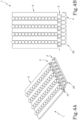
- Further features and advantages of the invention are more apparent from the exemplary, hence non-limiting description which follows of a preferred, but non-exclusive embodiment of a splicing apparatus as illustrated in the accompanying drawings, in which:
-
Figures 1A to 12A illustrate perspective views of the feeding apparatus according to the invention in different operating steps; -
Figures 1B to 12B illustrate plan views of the feeding apparatus according to the invention in different operating steps, corresponding to those ofFigures 1A-12A ; -
Figure 1C shows an enlarged detail fromFigure 1A . - The
reference numeral 1 denotes anapparatus 1 for feeding articles A to a pickup station ST, comprising: - a
conveyor 2 comprising a plurality of parallel feed lines L1, L2, L3, L4, each feed line L1, L2, L3, L4 being configured to contain a plurality of sequentially disposed articles A and being provided with a respective terminal end T1, T2, T3, T4; - a first
movable element 3, disposed at the terminal end of the feed lines L1, L2, L3, L4 and provided with a plurality of first seats S1 for receiving articles A; - a second
movable element 4, disposed at the terminal end of the feed lines L1, L2, L3, L4 and provided with a plurality of second seats S2 for receiving articles A. - It should be noted that in the example illustrated in
Figures 1A-12A and 1B-12B there are 4 feed lines L1, L2, L3, L4 illustrated. - In these feed lines L1, L2, L3, L4, as shown in the accompanying
Figures 1A-12A and 1B-12B , the articles A are fed along a predetermined direction X. - It should be noted that the feed lines L1, L2, L3, L4 extend along the direction X.
- The articles are fed along the feed lines L1, L2, L3, L4 in rows, that is to say, one behind the other along the predetermined conveying direction X. It should be noted that the feed lines L1, L2, L3, L4 are defined by side walls P1, P2, P3, P4, P5 on the right and left.
- In particular, each feed line L1, L2, L3, L4 is defined by a right-hand wall and a left-hand wall.
- The central feed lines L2, L3 have a wall (right and/or left) in common with other feed lines.
- Preferably, the
apparatus 1 comprises vibrating means (not illustrated) associated with the feed lines L1, L2, L3, L4, to allow the articles A to be moved along the lines. - It will be understood that the articles A can be fed along the feed lines L1, L2, L3, L4 in a plurality of modes (pushed by pushing devices, driven by a belt, etc.).
- According to another aspect, the first and the second
movable elements - It should be noted that the position P1 for receiving articles A and position P2 for releasing articles A are, for each of the first element or second
movable elements - In short, it should be noted that the first and second
movable elements - It should be noted that the expression the first and second
movable elements movable elements 3 must be moved simultaneously, but on the contrary it means that there must be a relationship between the position of one and the position of the other between the first and the secondmovable element 3, and consequently the movement of one relative to the other (of the two movable elements) must occur according to a predetermined relationship. These drawings are described in more detail below. - According to another aspect, one between the first and the second
movable elements movable elements - In practice, as shown in
Figures 4A, 4B ,5A and 5B , when the firstmovable element 3 is moved from the pickup up position P1 to the releasing position P2 of the articles A, the secondmovable element 4 is in the retracted position P3. Similarly, when thesecond element 4 is moved from the pickup position P1 to the releasing position P2 of the articles A, the firstmovable element 3 is in the retracted position P3. - In that way, there is no interference between the first and
second elements - According to another aspect, preferably, the first
movable element 3 and the secondmovable element 4 comprise a number of first and second seats S1, S2 at least equal to the number of feed lines L1, L2, L3, L4. - It should be noted that the first seats are subdivided into a first group S1A and into a second group S1B.
- Similarly, the second seats are subdivided into a first group S2A and into a second group S2B.
- The seats of the first group, first and second, S1A and S2A, are the seats designed to contain the articles to transfer them from the pickup position P1 to the releasing position P2.
- On the other hand, the seats of the second group, first or second, S1B and S2B, of one of the two movable elements (3, 4) contain the articles A only at the pickup position P1, partly superposing over time with the seats of the first group, first or second, S1A and S2A, designed to receive and transfer the articles from the pickup position P1 to the releasing position P2.
- In essence, the seats of the second group, first or second, S1B and S2B only temporarily receive the articles A and do not transfer the articles A received.
- With reference to an article A, in fact, as shown in
Figure 7 , the article A is present, at a given moment in time, both in a seat of the second group (S1B, S2B) of one of the two movable elements (3, 4) and in a seat of the first group (S1A, S2A) of the other of the two movable elements (4, 3). - As shown in the drawings, the first
movable element 3 and the secondmovable element 4 comprise a number of first and second seats S1, S2 equal to the number of feed lines L1, L2, L3, L4. - According to yet another aspect, the first
movable element 3 and the secondmovable element 4 are identical to each other. - It should also be noted that the first
movable element 3 and the secondmovable element 4 are shaped like prongs. - According to another aspect, one between the first and the second
movable element movable element - Basically, according to this aspect, when one of the two movable elements, first or second, is in the releasing position P2, the other is moved to the position P1 for picking up particles A.
- In this way, an article arriving from the feed lines L1, L2, L3, L4 is received inside the seats (first or second) of the movable element (first or second) moved from the retracted position P3 away from the position P1 for picking up articles A.
- This aspect is illustrated in
Figures 6A, 6B and7A, 7B . - According to another aspect, the article A receiving position P1 and the article A releasing position P2 are the same for the first and the second
movable elements - In this way, advantageously, the picking up and the releasing of the articles A always occurs in the same plan position.
- In particular, the fact that the articles A are always released in the same position, in plan view, makes it possible to prepare a pickup station ST which can always pick up the articles in the same position in plan view.
- This is extremely advantageous, since it is possible to use, in the pickup station ST, pickup devices with standard mechanics, the repetitive movement of which does not need particularly sophisticated controls.
- According to another aspect, the first and second seats S1, S2 are arcuate in shape.
- According to yet another aspect, the first seats S1 are equispaced from each other and the second seats S2 are equispaced from each other.
- It should also be noted that, preferably, the
apparatus 1 comprises a control unit 5 and at least one actuating unit 6. - It should be noted that the actuating unit 6 is connected to the first and second
movable elements -
Figure 1 is a schematic plan view of the actuating unit 6. - For simplicity, the actuating unit 6 is only illustrated in the plan view of
Figure 1 . - According to an aspect, as illustrated in
Figure 1 , the actuating unit 6 may comprise at least a first actuating unit 6A, connected to the firstmovable element 3 for moving it, and a second actuating unit 6B, connected to the secondmovable element 4 for moving it. - It should be noted that the first and/or the second actuating units 6A, 6B may comprise one or more actuators, for example as illustrated in
Figure 1 an actuator for moving along the direction X and an actuator for moving along the direction Y. - According to another aspect, a system is defined for moving articles A comprising the
apparatus 1 for feeding the articles A described above and a pickup station ST. - The pickup station ST comprises a plurality of pickup devices (not illustrated), operating at the article A releasing position P2, to pick up articles from the first seats S1 or second seats S2 disposed at the above-mentioned article A releasing position P2.
- It should be noted that the movement system forms part of a packaging apparatus.
- Preferably, the articles A are caps of bottles.
- The invention also relates to a method for feeding articles A to a pickup station ST, comprising the following steps:
- providing a first
movable element 3 having a plurality of first seats S1 for receiving articles A and configured to be moved along a first path PS1; - providing a second
movable element 4 having a plurality of second seats S2 for receiving articles A and configured to be moved along a second path PS2 at least partly (preferably entirely) overlapping the first path PS1; - feeding articles in sequence along a plurality of parallel feed lines L1, L2, L3, L4 along a conveying direction X;
- moving the first and the second
movable element - an article A receiving position P1 where articles A can be picked up by terminal ends T1, T2, T3, T4 of the feed lines L1, L2, L3, L4;
- an article releasing position P2, disposed laterally with respect to the article pickup position P1, where articles can be released to the pickup station ST;
- a retracted position P3 away along the conveying direction X with respect to the terminal ends T1, T2, T3, T4 (and of non-interference between the first and second
movable elements 3, 4).
- According to another aspect, the step of moving the first and the second
movable element movable element movable element - According to another aspect, the step of moving the first and the second
movable element movable element - According to another aspect, the step of moving the first and the second
movable elements movable elements movable elements - According to yet another aspect, the step of moving the first and the second
movable element - disposing the first
movable element 3 at the article A receiving position P1 and disposing the secondmovable element 4 at the retracted position P3 (Figure 1 ); - receiving articles A in the first seats S1 of the first
movable element 3 disposed at the article A receiving position P1 (Figures 2A, 2B ,3A, 3B ); - moving the first
movable element 3 from the article A receiving position P1 to the article releasing position P2 (Figures 4A and 4B ); - moving the second
movable element 4 from the retracted position P3 to the article A receiving position P1 (Figures 5A, 5B and6A, 6B ); - receiving articles A in the second seats S2 of the second
movable element 4 disposed at the article A receiving position P1 (Figures 7A and 7B ); - moving the first
movable element 3 from the article A releasing position P2 to the retracted position P3 (Figures 8A and 8B ); - moving the second
movable element 4 from the article A receiving position P1 to the article releasing position P2 (Figure 9A, 9B and10A, 10B ). - According to another aspect, the method comprises a step of picking up the articles A from the first seats S1 after the step of moving the first
movable element 3 from the position P1 for receiving articles A to the position P2 for releasing articles (Figures 6A, 6B ). - According to another aspect, the method comprises a step of picking up the articles A from the second seats S2 after the step of moving the second
movable element 4 from the position P1 for receiving articles A to the position P2 for releasing articles (Figures 11A, 11B ). - It should be noted, therefore, that cyclically, according to the method, the
first element 3 and thesecond element 4 occupy the article A receiving P1, the article A releasing position P2 and the retracted position P3. - It should be noted that the motion of the
first element 3 and of thesecond element 4 is a motion along a closed path (PS1, PS2) between these positions. - More specifically, the
first element 3 and thesecond element 4 are configured to move along a rectangular path, wherein there are two lateral movements (one in the direction from the position P1 for receiving articles A to the position P2 for releasing articles A and another in a direction parallel to the direction from the position P2 for releasing articles A to the position P1 for receiving articles A) and two movements in the direction X for conveying the articles A in the feed lines L1, L2, L3, L4 (one away from the terminal ends T1, T2, T3, T4 and another towards the terminal ends). - It should be noted that the first and second movable elements (3, 4) are each movable along a respective closed path PS1, PS2; the closed paths PS1, PS2 are offset from each other in height.
- According to yet another aspect, the step of moving the first and the second
movable elements moveable elements 3, 4: - moving the first or the second movable element (3, 4) along a first stretch K1 of the conveying path sideways relative to the feed lines L1, L2, L3, L4 in the direction from the article A pickup position P1 to the article A releasing position P2;
- moving the first or the second movable element (3, 4) along a second stretch K2 of the conveying path away (along the conveying direction X) from the terminal ends T1, T2, T3, T4 of the feed lines L1, L2, L3, L4 (along the article A conveying direction X);
- moving the first or the second movable element (3, 4) along a third stretch K3 of the conveying path sideways relative to the feed lines L1, L2, L3, L4 in a direction parallel to the direction from the article A releasing position P2 to the article A receiving position P1;
- moving the first or the second movable element (3, 4) along a fourth stretch K4 of the conveying path towards (along the conveying direction X) the terminal ends T1, T2, T3, T4 of the feed lines L1, L2, L3, L4 (along the article A conveying direction X).
- According to another aspect, the step of cyclically repeating the above-mentioned motion sequence along a respective closed conveying path (PS1, PS2) comprises moving (for each moment in time) the first and the second movable elements (3, 4) along different stretches K1, K2, K3, K4 of the path.
- It should be noted that the conveying paths PS1, PS2 of the first and second movable elements (3, 4) are preferably superposed on each other, that is to say, positioned at different heights.
- Basically, the first and second
movable elements - The first and second
movable elements - It should also be noted that the first and second
movable elements first element 3 is on a certain stretch of the path (for example, the first K1), thesecond element 4 is on a different stretch of the path. - For this reason, the step of cyclically repeating the above-mentioned motion sequence along a respective closed conveying path (PS1, PS2) comprises moving the first and the second movable elements (3, 4) along different stretches (K1, K2, K3, K4) of the path.
- It should be noted, in particular, that the first and second
movable elements movable elements movable elements - It should be noted that in
Figures 6A, 6B and11A and 11B some articles A have an "X" at the top: these articles A are being picked up by the pickup station ST and have therefore only been illustrated for convenience in that position, being able to also be in a different position.
Claims (20)
- An apparatus (1) for feeding articles (A) to a pickup station (ST), comprising:- a conveyor (2) comprising a plurality of parallel feed lines (L1, L2, L3, L4), each feed line (L1, L2, L3, L4) being configured to convey a plurality of sequentially disposed articles (A) along a conveying direction (X) and being provided with a respective terminal end (T1, T2, T3, T4);- a first movable element (3), disposed at the terminal end of the feed lines (L1, L2, L3, L4) and provided with a plurality of first seats (S1) for receiving articles (A);- a second movable element (4), disposed at the terminal end of the feed lines (L1, L2, L3, L4) and provided with a plurality of second seats (S2) for receiving articles (A),the first and the second movable element (3, 4) being configured to move in sync sideways and away from each other along the conveying direction (X) relative to the terminal ends (T1, T2, T3, T4) of the feed lines (L1, L2, L3, L4), on paths (PS1, PS2) which at least partly overlap, to allow picking up articles (A) from the feed lines (L1, L2, L3, L4) at an article (A) receiving position (P1), and to allow releasing articles (A) to the pickup station (ST) at an article (A) releasing position (P2) located laterally with respect to the article (A) receiving position (P1),one between the first and the second movable element (3, 4) being configured to be disposed at a retracted, away position (P3) at least during the movement of the other between the first and the second movable element (4,3) from the pickup position (P1) to the releasing position (P2) of the articles (A).
- The feeding apparatus (1) according to the preceding claim, wherein the first movable element (3) and the second movable element (4) comprise a number of first and second seats (S1, S2) at least equal to the number of feed lines (L1, L2, L3, L4).
- The feeding apparatus (1) according to either of the preceding claims, wherein the first movable element (3) and the second movable element (4) are identical.
- The feeding apparatus (1) according to any one of the preceding claims, wherein one between the first and the second movable element (3, 4) is configured to be moved from the retracted, away position (P3) to the article (A) receiving position (P1) when the other between the first and the second movable element (4,3) is disposed at the article (A) releasing position (P2).
- The feeding apparatus (1) according to any one of the preceding claims, wherein the article (A) receiving position (P1) and the article (A) releasing position (P2) are, when observed in a plan view, the same for the first and the second movable element (3, 4).
- The feeding apparatus (1) according to any one of the preceding claims, wherein the first and second seats (S1, S2) have an arcuate shape.
- The feeding apparatus (1) according to any one of the preceding claims, wherein the first seats (S1) are equispaced from each other and the second seats (S2) are equispaced from each other.
- The feeding apparatus (1) according to any one of the preceding claims, comprising a control unit (5) and at least one actuating unit (6), the actuating unit (6) being connected to the first and second movable elements (3, 4) to move them.
- The feeding apparatus (1) according to any one of the preceding claims, wherein the first seats (S1) are subdivided into a first group (S1A) and a second group (S1B) and wherein the second seats (S2) are subdivided into a first group (S2A) and a second group (S2B), the seats of the first groups (S1A, S2A) of first and second seats being adapted to contain the articles (A) to transfer them from the receiving position (P1) to the releasing position (P2), the first and the second movable element (3, 4) being moved in such a way that the seats of the second groups (S1B, S2B) of first and second seats of one of the two movable elements (3, 4) contain the articles (A) only at the receiving position (P1) where they temporarily partly overlap the seats of the first and second groups (S1A, S2A) of first and second seats.
- The feeding apparatus (1) according to any one of the preceding claims, wherein the first and the second movable element (3, 4) are configured to move in sync so as to cyclically repeat the following operating sequence:- disposing the first movable element (3) at the article (A) receiving position (P1) and disposing the second movable element (4) at the retracted position (P3);- moving the first movable element (3) from the article (A) receiving position (P1) to the article releasing position (P2);- moving the second movable element (4) from the retracted position (P3) to the article (A) receiving position (P1);- moving the first movable element (3) from the article (A) releasing position (P2) to the retracted position (P3);- moving the second movable element (4) from the article (A) receiving position (P1) to the article releasing position (P2).
- The feeding apparatus (1) according to any one of the preceding claims, wherein the first and the second movable element (3, 4) are each configured to be moved along a respective closed conveying path (PS1, PS2) according to the following motion sequence:- moving the first or the second movable element (3, 4) along a first stretch (K1) of the conveying path sideways relative to the feed lines (L1, L2, L3, L4) from the article (A) receiving position (P1) to the article (A) releasing position (P2);- moving the first or the second movable element (3, 4) along a second stretch (K2) of the conveying path away from the terminal ends (T1, T2, T3, T4) of the feed lines (L1, L2, L3, L4) along the article (A) conveying direction (X);- moving the first or the second movable element (3, 4) along a third stretch (K3) of the conveying path sideways relative to the feed lines (L1, L2, L3, L4) in a direction parallel to the direction from the article (A) releasing position (P2) to the article (A) receiving position (P1);- moving the first or the second movable element (3, 4) along a fourth stretch (K4) of the conveying path towards the terminal ends (T1, T2, T3, T4) of the feed lines (L1, L2, L3, L4) along the article (A) conveying direction (X).
- The feeding apparatus (1) according to the preceding claim, wherein the step of cyclically repeating the aforementioned motion sequence along a respective closed conveying path (PS1, PS2) comprises moving the first and the second movable element (3, 4) along different stretches (K1, K2, K3, K4) of the path.
- A system for moving articles (A), comprising the apparatus (1) for feeding the articles (A) according to any one of the preceding claims, and a pickup station (ST), comprising a plurality of pickup devices, operating at the article (A) releasing position (P2), to pick up articles from the first seats (S1) or second seats (S2) disposed at the article (A) releasing position (P2).
- A method for feeding articles (A) to a pickup station (ST), comprising the following steps:- providing a first movable element (3) having a plurality of first seats (S1) for receiving articles (A) and configured to be moved along a first path (PS1);- providing a second movable element (4) having a plurality of second seats (S2) for receiving articles (A) and configured to be moved along a second path (PS2) at least partly overlapping the first path (PS1);- feeding articles in sequence along a plurality of parallel feed lines (L1, L2, L3, L4) along a conveying direction (X);- moving the first and the second movable element (3, 4) in sync, sideways and along the conveying direction (X) relative to the terminal ends (T1, T2, T3, T4) of the feed lines (L1, L2, L3, L4), between:- an article (A) receiving position (P1) where articles (A) can be picked up by terminal ends (T1, T2, T3, T4) of the feed lines (L1, L2, L3, L4);- an article releasing position (P2), disposed laterally with respect to the article pickup position (P1), where articles can be released to the pickup station (ST);- a retracted position (P3) away from the terminal ends (T1, T2, T3, T4) along the conveying direction (X);and wherein the step of moving the first and the second movable element (3, 4) in sync comprises the step of disposing one between the first and the second movable element (3, 4) at the retracted, away position (P3) at least during the movement of the other between the first and the second movable element (4,3) from the pickup position (P1) to the releasing position (P2) of the articles (A).
- The method according to the preceding claim, wherein the step of moving the first and the second movable element (3, 4) in sync, sideways and along the conveying direction (X) relative to the terminal ends (T1, T2, T3, T4) of the feed lines (L1, L2, L3, L4) comprises a step of moving the first and the second movable element (3, 4) in sequence, respectively to the article (A) receiving position (P1), to the article releasing position (P2) and to the retracted, away position (P3).
- The method according to claim 14 or 15, wherein the step of moving the first and the second movable element (3, 4) in sync, sideways and along the conveying direction (X) relative to the terminal ends (T1, T2, T3, T4) of the feed lines (L1, L2, L3, L4) comprises a step of moving one between the first and the second movable element (3, 4) from the retracted position (P3) to the article (A) receiving position (P1) when the other between the first and the second movable element (4,3) is disposed at the article (A) releasing position (P2).
- The method according to claim 14 to 16, wherein the step of moving the first and the second movable element (3, 4) in sync, sideways and along the conveying direction (X) relative to the terminal ends (T1, T2, T3, T4) of the feed lines (L1, L2, L3, L4) comprises cyclically repeating the following operating sequence:- disposing the first movable element (3) at the article (A) receiving position (P1) and disposing the second movable element (4) at the retracted position (P3);- receiving articles (A) in the first seats (S1) of the first movable element (3) disposed at the article (A) receiving position (P1);- moving the first movable element (3) from the article (A) receiving position (P1) to the article releasing position (P2);- moving the second movable element (4) from the retracted position (P3) to the article (A) receiving position (P1);- receiving articles (A) in the second seats (S2) of the second movable element (4) disposed at the article (A) receiving position (P1);- moving the first movable element (3) from the article (A) releasing position (P2) to the retracted position (P3);- moving the second movable element (4) from the article (A) receiving position (P1) to the article releasing position (P2).
- The method according to the preceding claim, comprising a step of picking up the articles (A) from the first seats (S1) after the step of moving the first movable element (3) from the article (A) receiving position (P1) to the article releasing position (P2), and a step of picking up the articles (A) from the second seats (S2) after the step of moving the second movable element (4) from the article (A) receiving position (P1) to the article releasing position (P2).
- The method according to any one of claims 14 to 18, wherein the step of moving the first and the second movable element (3, 4) in sync, sideways and along the conveying direction (X) relative to the terminal ends (T1, T2, T3, T4) of the feed lines (L1, L2, L3, L4) comprises a step of cyclically repeating the following motion sequence along a respective closed conveying path (PS1, PS2) for each of the first and the second movable element (3, 4):- moving the first or the second movable element (3, 4) along a first stretch (K1) of the conveying path sideways relative to the feed lines (L1, L2, L3, L4) in the direction from the article (A) receiving position (P1) to the article (A) releasing position (P2);- moving the first or the second movable element (3, 4) along a second stretch (K2) of the conveying path along the conveying direction (X) away from the terminal ends (T1, T2, T3, T4) of the feed lines (L1, L2, L3, L4);- moving the first or the second movable element (3, 4) along a third stretch (K3) of the conveying path sideways relative to the feed lines (L1, L2, L3, L4) in a direction parallel to the direction from the article (A) releasing position (P2) to the article (A) receiving position (P1);- moving the first or the second movable element (3, 4) along a fourth stretch (K4) of the conveying path along the conveying direction (X) towards the terminal ends (T1, T2, T3, T4) of the feed lines (L1, L2, L3, L4).
- The method according to the preceding claim, wherein the step of cyclically repeating the aforementioned motion sequence along a respective closed conveying path (PS1, PS2) comprises moving the first and the second movable element (3, 4) along different stretches (K1, K2, K3, K4) of the path.
Applications Claiming Priority (1)
| Application Number | Priority Date | Filing Date | Title |
|---|---|---|---|
| IT102023000024258A IT202300024258A1 (en) | 2023-11-16 | 2023-11-16 | APPARATUS AND METHOD OF FEEDING ITEMS TO A PICK-UP STATION |
Publications (1)
| Publication Number | Publication Date |
|---|---|
| EP4556413A1 true EP4556413A1 (en) | 2025-05-21 |
Family
ID=89722984
Family Applications (1)
| Application Number | Title | Priority Date | Filing Date |
|---|---|---|---|
| EP24212021.0A Pending EP4556413A1 (en) | 2023-11-16 | 2024-11-11 | Apparatus and method for feeding articles to a pickup station |
Country Status (2)
| Country | Link |
|---|---|
| EP (1) | EP4556413A1 (en) |
| IT (1) | IT202300024258A1 (en) |
Citations (5)
| Publication number | Priority date | Publication date | Assignee | Title |
|---|---|---|---|---|
| US4413720A (en) * | 1981-09-04 | 1983-11-08 | Pfleger Frederick W | Article handling apparatus |
| US6223884B1 (en) * | 1997-05-23 | 2001-05-01 | Ronchipack S.R.L. | Apparatus for automatically forming arrays of containers |
| DE10322476A1 (en) * | 2003-05-19 | 2004-12-16 | Robert Bosch Gmbh | Apparatus, in particular, for providing pharmaceutical containers with closure elements comprises a sorting device combined with a supply conveyor into a single functional unit |
| JP2009249113A (en) * | 2008-04-07 | 2009-10-29 | Tokyo Automatic Machinery Works Ltd | Compiling/carrying device of product |
| DE102020134792A1 (en) * | 2020-12-23 | 2022-06-23 | Bausch + Ströbel Maschinenfabrik Ilshofen GmbH + Co. KG | Sealing device for sealing pharmaceutical containers and system for processing pharmaceutical containers |
-
2023
- 2023-11-16 IT IT102023000024258A patent/IT202300024258A1/en unknown
-
2024
- 2024-11-11 EP EP24212021.0A patent/EP4556413A1/en active Pending
Patent Citations (5)
| Publication number | Priority date | Publication date | Assignee | Title |
|---|---|---|---|---|
| US4413720A (en) * | 1981-09-04 | 1983-11-08 | Pfleger Frederick W | Article handling apparatus |
| US6223884B1 (en) * | 1997-05-23 | 2001-05-01 | Ronchipack S.R.L. | Apparatus for automatically forming arrays of containers |
| DE10322476A1 (en) * | 2003-05-19 | 2004-12-16 | Robert Bosch Gmbh | Apparatus, in particular, for providing pharmaceutical containers with closure elements comprises a sorting device combined with a supply conveyor into a single functional unit |
| JP2009249113A (en) * | 2008-04-07 | 2009-10-29 | Tokyo Automatic Machinery Works Ltd | Compiling/carrying device of product |
| DE102020134792A1 (en) * | 2020-12-23 | 2022-06-23 | Bausch + Ströbel Maschinenfabrik Ilshofen GmbH + Co. KG | Sealing device for sealing pharmaceutical containers and system for processing pharmaceutical containers |
Also Published As
| Publication number | Publication date |
|---|---|
| IT202300024258A1 (en) | 2025-05-16 |
Similar Documents
| Publication | Publication Date | Title |
|---|---|---|
| CN109071125B (en) | Method and apparatus for handling piece goods moving in at least two parallel rows | |
| US10442638B2 (en) | Method and apparatus for conveying articles, piece goods and/or bundles within at least two conveying path sections | |
| CN102083697B (en) | Packaging machine and method for packaging objects | |
| US9604792B2 (en) | Device for transferring products from a feeder conveyor belt to a discharge conveyor belt using grippers, and method for operating the device | |
| CN205675479U (en) | For carrying the structure of article, part goods or bundle | |
| US11136199B2 (en) | Production of batches of products for palletizing in layers | |
| CN102811910B (en) | Method and machine for overpackaging articles to form lots of articles, of the kind including a plurality of articles and a cardboard overpackage | |
| US11053082B2 (en) | Method and apparatus for handling piece goods moved one after the other in at least one row | |
| US9573777B2 (en) | Transport device for conveying products | |
| CN110799435B (en) | Method and device for handling piece goods, goods and/or multi-piece goods | |
| CN113260585B (en) | Device for grouping containers | |
| WO2018064259A1 (en) | Case manipulator apparatus and method for use with an inline palletizing system | |
| US12129062B2 (en) | Packaging machine with a grouping device and method for producing single-layer groups of partially overlapping products | |
| CN108528820B (en) | Device for treating objects and method for exchanging at least one transport module and at least one work module of a device | |
| US10138078B2 (en) | De-stacking device for de-stacking layers of transport pallets with or without intermediary layers | |
| CN116867719A (en) | Product handling equipment, systems and related methods | |
| CN107667065A (en) | Sorting device for segregating articles | |
| CN109311601B (en) | Method and device for processing piece goods moving in at least one row in sequence | |
| US20240351802A1 (en) | A sorting device | |
| CN110709341B (en) | Method and apparatus for handling pieces, articles and/or multipacks | |
| CN110884903B (en) | Method and apparatus for handling piece goods | |
| WO2022249022A1 (en) | Station and method for feeding and orienting articles, in particular bottles of the pharmaceutical field | |
| KR20190030200A (en) | Bottle packaging system having bottle supply apparatus | |
| EP3453653B1 (en) | End of line pick and place unit | |
| CN109311602B (en) | Method and device for handling piece goods moving in sequence |
Legal Events
| Date | Code | Title | Description |
|---|---|---|---|
| PUAI | Public reference made under article 153(3) epc to a published international application that has entered the european phase |
Free format text: ORIGINAL CODE: 0009012 |
|
| STAA | Information on the status of an ep patent application or granted ep patent |
Free format text: STATUS: THE APPLICATION HAS BEEN PUBLISHED |
|
| AK | Designated contracting states |
Kind code of ref document: A1 Designated state(s): AL AT BE BG CH CY CZ DE DK EE ES FI FR GB GR HR HU IE IS IT LI LT LU LV MC ME MK MT NL NO PL PT RO RS SE SI SK SM TR |
|
| STAA | Information on the status of an ep patent application or granted ep patent |
Free format text: STATUS: REQUEST FOR EXAMINATION WAS MADE |
|
| 17P | Request for examination filed |
Effective date: 20251014 |