Field of the invention
-
The present invention relates to a capsule configured for preparing a beverage upon injection of liquid into the capsule. The present invention further relates to a method of manufacturing a capsule.
Background of the invention
-
Capsules for beverage preparation machines are well known in the art. Capsules are typically used for on demand dispensing of beverages, like coffee, tea, hot chocolate or the like, and enjoy popularity due to their fresh tasting, variability of flavors and the convenience of the beverage preparation.
-
In an eco-responsible approach, some existing capsules or pods are made of compostable materials. For instance, documents
WO 2016/139554 A1 ,
WO 2020/114995 A1 disclose a compostable coffee pod. In fact, regulations in some countries or regions which prescribe that capsules or pods must be made of compostable materials are already in place and/or are envisaged for the future. However, existing compostable capsules may have one or more drawbacks, in particular when used with the coffee machines currently on the market which may have been originally designed for non-compostable capsules.
-
It is thus an object of the present invention to provide a capsule, in particular a capsule made of one or more compostable materials, for use in a beverage preparation machine that shall ensure high quality and beverage consistency during preparation of the beverage. It is a further object of the present invention to provide a capsule, in particular a capsule made of one or more compostable materials, which provides an improved balance between preserving and/or protecting the contents of the capsule and a performance of the capsule with the available coffee machines. It is a further object of the present invention to provide a capsule, in particular a capsule made of one or more compostable materials, which has a configuration which facilitates manufacturing the capsule.
Solution to the problem
-
These, and optionally other objects, which become apparent upon reading the description, are solved by the subject-matter of the independent claims. Further embodiments and developments are provided in the dependent claims.
-
According to a first aspect of the present invention, a capsule is provided. The capsule is configured for preparing a beverage upon injection of liquid into the capsule. The capsule comprises a cup-shaped body including a side wall, a top opening, and a bottom opening. The body has a substantially cylindrical or frusto-conical shape. The body preferably is made of a first multilayer oxygen and/or moisture barrier material comprising a paper or cardboard and an organic and/or inorganic barrier layer, the paper or cardboard having a grammage comprised between 40 and 450 g/m2 and the first material having a cellulose content higher than 30%, preferably higher than 50%, more preferably higher than 90%. The capsule further comprises a bottom closure connected to the cup-shaped body to close the bottom opening and a sealing lid connected to the cup-shaped body to close the top opening.
-
In the context of the present invention, a multilayer material may be formed by a composite material comprising different types of materials (e.g, as discussed in more detail hereinafter) that are attached to each other, e.g., by coating and/or lamination. In other words, according to the present invention the multilayer oxygen and/or moisture barrier material may be a multilayer oxygen and/or moisture barrier laminate or a multilayer oxygen and/or moisture barrier material made by coating.
-
The capsule according to the present invention is based at least partially on the idea of configuring the capsule to be at least partially compostable, while providing the capsule with sufficient moisture resistant and/or barrier, in particular moisture barrier, properties.
-
The capsule is further at least partially based on the idea that configuring the paper or cardboard to have a grammage comprised between 40 and 450 g/m2 and a cellulose content higher than 30%, preferably higher than 50%, more preferably higher than 90%, provides the capsule with a sufficient rigidity, when used with the coffee machines currently on the market which may have been originally designed for non-compostable capsules. At the same time, the rigidity is limited, in particular by limiting the grammage of the paper or cardboard to 450 g/m2, which may facilitate the use of the capsule with the coffee machines currently on the market. Limiting the rigidity of the capsule may also facilitate the manufacturing process and/or the sealing effect of the sealing lid. In particular, configuring a capsule with a rigidity which is too high may make it more challenging and/or impossible to adequately form a rim and/or sufficiently seal the capsule.
-
The capsule according to the present invention is particularly intended for use in a capsule beverage preparation machine as known, for example, from
EP 0 512 470 A1 or
EP 2 919 628 A1 which are incorporated by reference herein in their entirety. Preferably, the capsule according to the present invention is configured such that it can be used as an alternative to known capsules typically used in such a machine.
-
The expression "compostable" may be understood as any material that complies with certain compostability standards. For example, industrial compostability is defined in European Norm EN 13432. Home compostability conditions are adapted based on national standards within certain testing specifications, such as TÜV testing specifications. Materials or products compliant with these standards can be recognized, for example, by a conformity mark stating their home compostability. Some examples of home compostability certifications at a national level include, but are not limited to, the following. For example, the certifier TÜV AUSTRIA BELGIUM offers such a home compostability certification scheme, and DIN CERTCO offers a certification for home compostability according to the Australian standard AS 5810. Italy has a national standard for composting at ambient temperature, UNI 11183:2006. In November 2015, the French Standard "NF T 51-800 Plastics - Specifications for plastics suitable for home composting" was introduced. This standard is covered in the DIN CERTCO scheme.
-
In the capsule according to the present invention, the side wall may comprises a top rim or top flange surrounding the top opening. The top rim or top flange may be integrally formed with the side wall. Alternatively or additionally, the side wall may comprise a bottom rim or bottom flange surrounding a bottom opening. The bottom rim or bottom flange may be integrally formed with the side wall. Such top and/or bottom rim or flange may allow for easier attachment of, and/or a better seal of the side wall to, the sealing lid and/or bottom closure, respectively.
-
The top and/or bottom rim or flange preferably is provided by a deformed portion of the cup-shaped body, more preferably by a deformed portion of the side wall. Preferably, the side wall is deformed after rolling the first material, e.g. into a cylinder or truncated cone. The side wall may be deformed by bending.
-
Where a top rim or top flange is provided, the sealing lid preferably is connected to the cup-shaped body via said top rim or flange. Where a bottom rim or bottom flange is provided, the bottom closure preferably is connected to the cup-shaped body via said bottom rim or flange.
-
In other embodiments, the side wall may be formed without a top rim or top flange, and/or without a bottom rim or bottom flange. This may allow for a simpler manufacturing process.
-
As will be appreciated by the skilled person, the cup-shaped body may be structured to have any of the following configurations: (i) a top rim or top flange and a bottom rim or bottom flange, (ii) a top rim or top flange but no bottom rim or bottom flange, (iii) a bottom rim or bottom flange but no top rim or top flange, or (iv) neither a top rim or top flange nor a bottom rim or bottom flange.
-
A diameter or width of the bottom closure may be less than a diameter or width of the top closure.
-
A diameter or width of the bottom opening may be less than a diameter or width of the top opening.
-
According to a first variation, the cup-shaped body, e.g. its bottom rim, folds around the bottom closure, preferably around a radially outer peripheral wall of the bottom closure. Preferably, the radially outer peripheral wall is cylindrical or frusto-conical. The radially outer peripheral wall may form a radially outermost portion of the bottom closure.
-
Preferably, the cup-shaped body, e.g. its bottom rim, folds around the bottom closure in a U shape. Preferably, the U-shape is open towards a top end of the capsule. In other words, the U-shape may be open in a direction facing towards the lid.
-
Preferably, the cup-shaped body, e.g. its bottom rim, folds radially inward around the radially outer peripheral wall.
-
Preferably, the cup-shaped body, e.g. its bottom rim, folding around the bottom closure forms a seal between the cup-shaped body and the bottom closure. Preferably, the seal is liquid and/or gas tight.
-
The bottom closure may further include a peripheral recess. The peripheral recess may be arranged in a radially outer portion of the bottom closure. Preferably, the peripheral recess is circular.
-
The peripheral recess may have a depth of at least 2 mm, preferably at least 4 mm.
-
Preferably, the radially outer peripheral wall delimits the peripheral recess.
-
Preferably, the cup-shaped body, e.g. its bottom rim, extends into the peripheral recess. In particular, a portion of the side wall of the cup-shaped body that is folded radially inwardly, may extend into the peripheral recess.
-
Preferably, the peripheral recess is open towards a bottom end of the capsule and/or in a direction facing away from the lid.
-
Preferably, the bottom closure is arranged radially within cup shaped body.
-
Preferably, the bottom closure is arranged at least partially within the cup-shaped body in an axial direction of said cup-shaped body and at least partially outside the cup-shaped body in said axial direction.
-
Preferably, the bottom closure comprises a radially inner peripheral wall. Preferably, the radially inner peripheral wall is cylindrical or frusto-conical. Preferably, the radially inner peripheral wall delimits the peripheral recess.
-
The radially inner peripheral wall may delimit an inner recess of the bottom closure. Preferably, the radially inner peripheral wall extends around the inner recess. The inner recess may be open in a direction facing the lid. In other words, the inner recess may form part of an inner cavity of the capsule.
-
Preferably, the radially inner peripheral wall extends around a bottom wall of the bottom closure. Preferably, the bottom wall extends perpendicularly to a longitudinal axis of the capsule.
-
Preferably, the bottom wall forms the bottom of the capsule and/or is arranged further axially towards a bottom end of the capsule than the cup-shaped body.
-
Preferably, the radially inner peripheral wall, the bottom wall, and the cup-shaped body together delimit an inner cavity of the capsule.
-
The side wall may have a continuous cylindrical or continuous conical shape.
-
In view of the overall design of the bottom closure and side wall, the capsule according to this first variation provides a strong connection and sealing integrity between the side wall of the cup-shaped body, e.g. its bottom rim, and the bottom closure. Meanwhile, perforation of the bottom closure by the type of openers provided in commonly used beverage preparation machines may still be ensured.
-
According to a second variation, the side wall may have a main section having a cylindrical shape and a bottom rim having a frusto-conical shape. Alternatively, the side wall may have a main section having a first frusto-conical shape and a bottom rim having a second frusto-conical shape. A cone angle of the second frusto-conical shape may be larger than a cone angle of the first frusto-conical shape. Such shapes may also be referred to as a goblet-shape in the context of the present invention. Such design may simplify the insertion and attachment of the bottom closure to the side wall. Furthermore, rigidity of the body is ensured while bending stresses on the first material are reduced. This may reduce the risk damaging the moisture barrier property of the first material (e.g., when a vacuum-deposited layer of aluminium is used).
-
Preferably, the bottom rim extends radially inward and/or towards a longitudinal axis of the capsule from the main section. As such, the bottom rim may also be referred to as a bottom flange.
-
Preferably, the bottom rim is angled with respect to the main section.
-
Preferably, the bottom closure is attached to an inner surface of the cup-shaped body, preferably to an inner surface of the bottom rim of the side wall. This provides for a stable connection between the two elements.
-
Preferably, the bottom closure has a frusto-conical shape.
-
Preferably, the bottom closure has a frusto-conical peripheral wall and a bottom wall closing a bottom end of said frusto-conical peripheral wall.
-
Preferably, an angle between the frusto-conical peripheral wall and the bottom wall is at least 120°, preferably at least 130°, more preferably at least 145°. Preferably, the angle is measured in a cross section of the capsule taken along the capsule's longitudinal axis.
-
Preferably, an angle between the frusto-conical peripheral wall and the bottom wall is 170° or less, preferably 160° or less, more preferably 155° or less. Preferably, the angle is measured in a cross section of the capsule taken along the capsule's longitudinal axis.
-
According to a third variation, the side wall may have a substantially continuous frusto-conical shape. The side wall may be devoid of a top rim or top flange. The side wall may be devoid of a bottom rim or bottom flange.
-
Also in this variation, the bottom closure preferably has a frusto-conical peripheral wall and a bottom wall closing a bottom end of said frusto-conical peripheral wall. The bottom wall may be flat.
-
Preferably, an angle between the frusto-conical peripheral wall and the bottom wall is 120° or less, preferably 110° or less, more preferably 100° or less. Preferably, the angle is measured in a cross section of the capsule taken along the capsule's longitudinal axis
Preferably, an angle between the frusto-conical peripheral wall and the bottom wall may be at least 95°. Preferably, the angle is measured in a cross section of the capsule taken along the capsule's longitudinal axis.
-
Preferably, the bottom closure is attached to an inner surface of the cup-shaped body, preferably to an inner surface of the side wall. Preferably, an outer surface of the frusto-conical peripheral wall of the bottom closure is attached to the inner surface of the side wall of the cup-shaped body. This provides for a stable connection between the two elements.
-
With the third variation, the cup-shaped body may be manufactured in a particularly cost-effective manufacture manner. Furthermore, bending of the cup shaped body may be avoided, thereby reducing the risk of any damage to, e.g., the moisture barrier properties (e.g., when a moisture barrier is provided by vacuum-deposited Al).
-
In any of the above variations, the cup-shaped body may include a bottom opening. Preferably, the bottom closure closes the bottom opening.
-
In any of the above variations, the cup-shaped body preferably is provided by forming the first material into a tubular structure. Forming may be performed by rolling the flat structure into a cylinder or conical cylinder and then seaming the longitudinal seal, by ultrasonic or heat sealing process.
-
A first peripheral end of the first material may be sealingly connected to a second peripheral end of the first material along a seam of the cup-shaped body. Preferably, the seam extends axially along the side wall. Preferably, the first peripheral end overlaps the second peripheral end along the seam. Preferably, a sealing strip extends around the first peripheral end and is attached to the second peripheral end.
-
Alternatively, the first peripheral end does not overlap the second peripheral end along the seam. Preferably, a sealing strip sealingly connects the first peripheral end to the second peripheral end. Preferably, the sealing strip extends along the inside of the cup-shaped body.
-
In any of the above variations, the bottom closure may be made from a second multilayer oxygen and/or moisture barrier material. The second material preferably comprises a paper or cardboard and an organic and/or inorganic barrier layer, the paper or cardboard preferably having a grammage comprised between 40 and 450 g/m2 and/or wherein the second material has a cellulose content higher than 30%, preferably higher than 50%, more preferably higher than 90%. The second material may be the same or different from the first material.
-
In any of the above variations, the cellulose content of the first and/or second material preferably is higher than 95%, preferably higher than 99%.
-
In any of the above variations, the first and/or second material, and/or a third material forming the lid, may comprise (a) a paperboard layer having a grammage between 120 g/m2 and 450 g/m2, (b) an optional adhesive layer having a grammage between 0.5 and 10 g/m2, (c) a paper layer having a grammage comprised between 40 and 120 g/m2, (d) the at least one organic and/or inorganic barrier layer, and € at least one organic heat seal layer. Preferably, the layers are provided in the order (a) €(e). Such materials have been found to be compostable while still providing sufficient barrier properties. The material may be formed as a laminate and/or by coating. As can be understood, in this case, the material contains a first layer of paper based material, the grammage of which is comprised between 40 and 450 g/m2, to which a further layer of paper based material is added.
-
Preferably, the at least one organic heat seal layer is made of an acrylic or methacrylic acid polymer or polyolefin grafted with at least one type of ionomer, preferably a sodium ionomer, or a starch-based heat sealing material.
-
Preferably, the heat seal layer is applied in an amount of between 2 and 20 g/m2, preferably in an amount of between 4 and 9 g/m2.
-
Preferably, a material of the organic barrier layer comprises or consists of: polyvinyl-alcohol (PVOH), butenediol-vinyl-alcohol-copolymer (BVOH), a PVOH copolymer, a polyglycolic acid (PGA), or a combination thereof.
-
Preferably, the organic barrier layer includes at least one of: a metallization coating, a SiOx based coating, and an AlOx based coating.
-
Preferably, the organic barrier layer is applied in an amount of 0.5 to 20 g/m2, preferably in an amount of 1 to 10 g/m2, more preferably in an amount of 2 to 8 g/m2.
-
Preferably, the at least one inorganic barrier layer is selected within the list of: metals, metalloids, or a combination thereof.
-
Preferably, the inorganic barrier layer has a thickness between 1 and 100 nm.
-
In any of the above variations, the body and/or the bottom closure preferably comprises at least 50 vol% paper, more preferably at least 60 vol% paper, more preferably at least 70 vol% paper, more preferably at least 80 vol% paper, more preferably at least 90 vol% paper, more preferably at least 95 vol% paper.
-
In any of the above variations, the first and/or second material preferably is compostable in accordance with EN 13432 or US ASTM D6400.
-
In any of the above variations, the lid is preferably formed from a nonwoven, a multilayer membrane, or a third multilayer oxygen and/or moisture barrier material. The third material may be the same or different from the first and/or second material.
-
In any of the above variations, the cup-shaped body preferably has a height of at least 10 mm, more preferably at least 15 mm, even more preferably at least 20 mm, even more preferably at least 22 mm, even more preferably at least 25 mm, even more preferably at least 27 mm, or even more preferably at least 28 mm.
-
In any of the above variations, the cup-shaped body preferably has a height of at most 60 mm, preferably at most 50 mm, more preferably at most 45 mm, even more preferably at most 40 mm, more preferably at most 35 mm, more preferably at most 33 mm, more preferably at most 30 mm or even more preferably at most 29 mm.
-
In any of the above variations, the cup-shaped body preferably has a diameter of at least 10 mm, preferably at least 15 mm, more preferably at least 20 mm, even more preferably at least 25 mm, even more preferably at least 27 mm, even more preferably at least 29 mm, even more preferably at least 30 mm, even more preferably at least 31 mm.
-
In any of the above variations, the cup-shaped body preferably has a diameter of at most 60 mm, preferably at most 50 mm, more preferably at most 45 mm, even more preferably at most 40 mm, even more preferably at most 35 mm, even more preferably at most 33 mm, even more preferably at most 31 mm.
-
In any of the above variations, the top rim or top flange of the cup-shaped body preferably has a radial width of at least 1 mm, preferably at least 2 mm, more preferably at least 2.5 mm, even more preferably at least 2.8 mm, even more preferably at least 3 mm, even more preferably at least 3.2 mm, even more preferably at least 3.4 mm.
-
In any of the above variations, the top rim or top flange of the cup-shaped body preferably has a radial width of at most 10 mm, preferably at most 8 mm, more preferably at most 6 mm, even more preferably at most 5 mm, even more preferably at most 4.5 mm, even more preferably at most 4 mm, even more preferably at most 3.8 mm, even more preferably at most 3.5 mm.
-
In any of the above variations, the wall of the cup-shaped body preferably has a thickness of at least 0.1 mm, preferably at least 0.13 mm, more preferably at least 0.15 mm, even more preferably at least 0.16 mm, even more preferably at least 0.17 mm, even more preferably at least 0.18 mm.
-
In any of the above variations, the side wall of the cup-shaped body preferably has a first wall thickness of at most 2 mm, preferably at most 1 mm, more preferably at most 0.5 mm, more preferably at most 0.4 mm, more preferably at most 0.3 mm, even more preferably at most 0.25 mm, even more preferably at most 0.22 mm, even more preferably at most 0.20 mm, even more preferably at most 0.19 mm.
-
In any of the above variations, the bottom closure, preferably a bottom wall and/or a peripheral wall of said bottom closure, preferably has a second wall thickness that is less than a first wall thickness of the side wall of the cup-shaped body. In this manner, piercing of the bottom wall by an opener of a beverage preparation machine may be facilitated.
-
Alternatively or additionally, in any of the above variations, the bottom closure may comprise one or more structurally weakened areas for forming one or more fluid inlets through the bottom closure. Preferably, the portions of the bottom closure that form the structurally weakened areas have a wall thickness that is less than a wall thickness of the surrounding areas of the bottom closure. Also in this manner, piercing of a wall of the capsule by an opener or water injector of a beverage preparation machine may be facilitated. Such water injectors usually take the form of needles, spikes or blades that inject water under pressure within the capsule (with or without perforating a wall of the capsule), so as to allow mixing of said water with an ingredient contained in the capsule, to form a beverage such as coffee for instance. It is also envisaged that one or more blades, spikes or needles may pierce through the sealing lid, with the water under pressure being injected into the capsule through said lid and the beverage exiting the capsule, e.g., through the bottom closure.
-
A further aspect of the present invention, which may form an independent aspect of the present invention, relates to a method of manufacturing a capsule, in particular a capsule according to the first aspect and embodiments thereof. The method includes the steps of:
- a) forming a side wall of a cup-shaped body by rolling a first multilayer oxygen and/or moisture barrier material comprising a paper or cardboard and an organic and/or inorganic barrier layer, the paper or cardboard having a grammage comprised between 40 and 450 g/m2 and the first material having a cellulose content higher than 30%, preferably higher than 50%, more preferably higher than 90%, into a cylindrical or conical shape;
- b) connecting a bottom closure to the cup-shaped body to close a bottom opening of said cup-shaped body; and
- c) connecting a lid to the cup-shaped body to close a top opening of said cup-shaped body.
-
The method may include, e.g. after step a), the forming of a bottom rim or bottom flange on the cup-shaped body, in particular on the side wall, e.g. by bending. In this case, the bottom closure may be attached to the cup shaped body in step b) via the bottom rim or bottom flange.
-
Alternatively or additionally, the method may include, e.g. after step a), the forming of a top rim or top flange on the cup-shaped body, in particular on the side wall, e.g. by bending. In this case, the lid may be attached to the cup shaped body in step c) via the top rim or top flange.
-
Preferably, the bottom closure is inserted into the cup-shaped body through the top opening of the latter.
-
The method preferably comprises, after or as part of step a) sealing a longitudinal seam along a height of the cup-shaped body, preferably to close said body into the shape of a cylinder or cone or truncated cone. Sealing may be performed by ultrasonic energy or a heat sealing process.
-
In a first variation, a first peripheral end of the first material overlaps with a second peripheral end of the first material when the side wall of the cup-shaped body is rolled, and the method comprises a step of sealingly attaching the first end to the second end.
-
In a second variation, a first peripheral end of the first material is sealingly connected with a second peripheral end of the first material without overlapping, and the method comprises a step of providing a sealing strip for connecting the first peripheral end to the second peripheral end.
-
The method may be carried out by first rolling the first material, e.g. into a cylinder or truncated cone, then (optionally) forming the bottom rim or flange (preferably by bending the side wall), then attaching the bottom closure to the cup-shaped body (through the bottom rim or flange, or directly to the sidewall of the body), then (optionally) forming the top rim or flange (preferably by bending the side wall), and then connecting the lid to the body (through the bottom rim or flange, or directly to the sidewall of the body). Other shapes, such as a prism or truncated pyramid, may also be formed in the folding process.
-
Another aspect of the present invention, which may form an independent aspect of the present invention, relates to a use of a capsule, in particular to a use of a capsule according to the first aspect or embodiments or variations thereof, in a beverage preparation machine. The machine comprises one or more blades, spikes or needles, preferably a plurality of blades, spikes or needles. The blades, spikes or needles may be provided by an opener of the machine. The blades, spikes or needles may pierce through the bottom closure.
-
Preferably, the one or more blades, spikes or needles do not pierce through the side wall of the cup-shaped body.
-
Preferably, the beverage flows out from the capsule through the lid. Preferably, the lid is pierced by a pyramid plate.
-
Another aspect of the present invention, which may form an independent aspect of the present invention, relates to a system comprising a capsule, in particular a capsule according to the first aspect or embodiments thereof, and a beverage preparation machine. The beverage preparation machine comprises one or more blades, spikes or needles, preferably a plurality of blades, spikes or needles. The blades, spikes or needles are configured to pierce through the bottom closure. Any other means able to inject water within the capsule are also encompassed.
-
Preferably, the one or more blades, spikes or needles are configured to not pierce through the side wall of the cup-shaped body.
-
Preferably, the beverage preparation machine comprises a pyramid plate configured to open the lid, preferably by rising pressure within the capsule. Preferably, a brewed beverage is configured to flow out of the capsule through the lid and/or through the pyramid plate to an outlet of the machine.
-
The following aspects are preferred embodiments of the invention:
- 1. A capsule (10) configured for preparing a beverage upon injection of liquid into the capsule (10), the capsule (10) comprising:
- a cup-shaped body (12) including a side wall (14), the body (12) having a substantially cylindrical or frusto-conical shape with a top opening (16) and a bottom opening (26), preferably wherein the body (12) is made of a first multilayer oxygen and/or moisture barrier material (20) comprising a paper or cardboard and an organic and/or inorganic barrier layer, preferably wherein the paper or cardboard has a grammage comprised between 40 and 450 g/m2 and the first material has a cellulose content higher than 30%, preferably higher than 50%, more preferably higher than 90%;
- a bottom closure (22) connected to the cup-shaped body (12) to close the bottom opening (26) of the cup-shaped body (12); and
- a sealing lid (24) connected to the cup-shaped body (12) to close the top opening (16) of the cup-shaped body (12);
preferably wherein:
- the side wall (14) comprises a top rim or top flange (18) surrounding the top opening (16), more preferably wherein the top rim (18) is integrally formed with the side wall (14); and/or
- wherein the side wall (14) comprises a bottom rim or bottom flange surrounding the bottom opening (26), more preferably wherein the bottom rim or bottom flange is integrally formed with the side wall (14).
- 2. The capsule according to aspect 1, wherein the cup-shaped body folds around the bottom closure, preferably around a radially outer peripheral wall of the bottom closure, more preferably wherein the radially outer peripheral wall is cylindrical or frusto-conical and/or wherein the radially outer peripheral wall forms a radially outermost portion of the bottom closure.
- 3. The capsule according to aspect 2, wherein the cup-shaped body folds around the bottom closure in a U shape, preferably wherein the U-shape is open towards a top end of the capsule.
- 4. The capsule according to aspect 2 or 3, wherein the cup-shaped body folds radially inward around the radially outer peripheral wall.
- 5. The capsule according to any of the preceding aspects, wherein the cup-shaped body folding around the bottom closure forms a seal between the cup-shaped body and the bottom closure, preferably wherein the seal is liquid and/or gas tight.
- 6. The capsule according to any of the preceding aspects, wherein the bottom closure includes a peripheral recess, preferably wherein the peripheral recess is circular.
- 7. The capsule according to aspect 6, wherein the peripheral recess is arranged in a radially outer portion of the bottom closure.
- 8. The capsule according to aspect 6 or 7, wherein the radially outer peripheral wall delimits the peripheral recess.
- 9. The capsule according to any of aspects 6 to 8, wherein the cup-shaped body extends into the peripheral recess.
- 10. The capsule according to any of aspects 6 to 9, wherein the peripheral recess is open towards a bottom end of the capsule.
- 11. The capsule according to any of the preceding aspects, wherein the bottom closure is arranged radially within cup shaped body.
- 12. The capsule according to any of the preceding aspects, wherein the bottom closure comprises a radially inner peripheral wall, preferably wherein the radially inner peripheral wall is cylindrical or frusto-conical.
- 13. The capsule according to aspect 12, wherein the radially inner peripheral wall delimits the peripheral recess.
- 14. The capsule according to aspect 12 or 13, wherein the radially inner peripheral wall delimits an inner recess of the bottom closure, preferably wherein the radially inner peripheral wall extends around the inner recess.
- 15. The capsule according to any of aspects 12 to 14, wherein the radially inner peripheral wall extends around a bottom wall of the bottom closure, preferably wherein the bottom wall extends perpendicularly to a longitudinal axis of the capsule.
- 16. The capsule according to any of aspects 12 to 15, wherein the bottom wall forms the bottom of the capsule and/or is arranged further axially towards a bottom end of the capsule than the cup-shaped body.
- 17. The capsule according to any of aspects 12 to 16, wherein the radially inner peripheral wall, the bottom wall, and the cup-shaped body together delimit an inner cavity of the capsule.
- 18. The capsule according to aspect 1, wherein the cup-shaped body has a goblet-shape.
- 19. The capsule according to aspect 1 or 18,
- wherein the side wall has a main section having a cylindrical shape and a bottom rim having a frusto-conical shape, or
- wherein the side wall has a main section having a first frusto-conical shape and a bottom rim having a second frusto-conical shape, wherein a cone angle of the second frusto-conical shape is larger than a cone angle of the first frusto-conical shape.
- 20. The capsule according to aspect 19, wherein the bottom rim extends radially inward and/or towards a longitudinal axis of the capsule from the main section.
- 21. The capsule according to aspect 19 or 20, wherein the bottom rim is angled with respect to the main section.
- 22. The capsule according to any of aspects 18 to 21, wherein the bottom closure is attached to an inner surface of the cup-shaped body, preferably to an inner surface of the bottom rim of the side wall.
- 23. The capsule according to any of the preceding aspects, wherein the bottom closure has a frusto-conical shape.
- 24. The capsule according to any of the preceding aspects, wherein the bottom closure has a frusto-conical peripheral wall and a bottom wall closing a bottom end of said frusto-conical peripheral wall.
- 25. The capsule of aspect 24, wherein an angle between the frusto-conical peripheral wall and the bottom wall is at least 120°, preferably at least 130°, more preferably at least 145°, preferably wherein the angle is measured in a cross section of the capsule taken along the capsule's longitudinal axis.
- 26. The capsule of aspect 24 or 25, wherein an angle between the frusto-conical peripheral wall and the bottom wall is 170° or less, preferably 160° or less, more preferably 155° or less, preferably wherein the angle is measured in a cross section of the capsule taken along the capsule's longitudinal axis.
- 27. The capsule of aspect 24, wherein an angle between the frusto-conical peripheral wall and the bottom wall is 120° or less, preferably 110° or less, more preferably 100° or less, preferably wherein the angle is measured in a cross section of the capsule taken along the capsule's longitudinal axis
- 28. The capsule of aspect 24 or 27, wherein an angle between the frusto-conical peripheral wall and the bottom wall is at least 95°, preferably wherein the angle is measured in a cross section of the capsule taken along the capsule's longitudinal axis.
- 29. The capsule according to any of aspects 24 to 28, wherein an outer surface of the frusto-conical peripheral wall of the bottom closure is attached to the inner surface of the side wall of the cup-shaped body.
- 30. The capsule according to any of the preceding aspects, wherein the cup-shaped body includes a bottom opening and wherein the bottom closure closes the bottom opening.
- 31. The capsule according to any of the preceding aspects, wherein the bottom closure is attached to an inner surface of the cup-shaped body, preferably to an inner surface of the side wall.
- 32. The capsule according to any of the preceding aspects, wherein the cup-shaped body is provided by forming the first material into a tubular structure.
- 33. The capsule according to any of the preceding aspects, wherein a first peripheral end of the first material is sealingly connected to a second peripheral end of the first material along a seam of the cup-shaped body, preferably wherein the seam extends axially along the side wall.
- 34. The capsule according to aspect 33, wherein the first peripheral end overlaps the second peripheral end along the seam.
- 35. The capsule according to aspect 33 or 34, wherein a sealing strip extends around the first peripheral end and is attached to the second peripheral end.
- 36. The capsule according to aspect 33, wherein the first peripheral end does not overlap the second peripheral end along the seam.
- 37. The capsule according to aspect 36, wherein a sealing strip sealingly connects the first peripheral end to the second peripheral end, preferably wherein the sealing strip extends along the inside of the cup-shaped body.
- 38. The capsule according to any of the preceding aspects, wherein the bottom closure is made from a second multilayer oxygen and/or moisture barrier material comprising a paper or cardboard and an organic and/or inorganic barrier layer, the paper or cardboard having a grammage comprised between 40 and 450 g/m2 and the second material having a cellulose content higher than 30%, preferably higher than 50%, more preferably higher than 90%, wherein the second material is the same or different from the first material.
- 39. The capsule according to any of the preceding aspects, wherein the cellulose content of the first and/or second material is higher than 95%, preferably higher than 99%.
- 40. The capsule according to any of the preceding aspects, wherein the first and/or second material comprises:
- (a) a paperboard layer having a grammage between 120 g/m2 and 450 g/m2,
- (b) an optional adhesive layer having a grammage between 0.5 and 10 g/m2,
- (c) a paper layer having a grammage comprised between 40 and 120 g/m2,
- (d) the at least one organic and/or inorganic barrier layer; and
- (e) at least one organic heat seal layer;
preferably wherein the layers are provided in the order (a) to (e). - 41. The capsule according to aspect 40, wherein the at least one organic heat seal layer is made of an acrylic or methacrylic acid polymer or polyolefin grafted with at least one type of ionomer, preferably a sodium ionomer, or a starch-based heat sealing material.
- 42. The capsule according to aspect 40 or 41, wherein the heat seal layer is applied in an amount of between 2 and 20 g/m2, preferably in an amount of between 4 and 9 g/m2.
- 43. The capsule according to any of aspects 40 to 42, wherein a material of the organic barrier layer comprises or consists of: polyvinyl-alcohol, PVOH, ethylene vinyl alcohol, EVOH, butenediol-vinyl-alcohol-copolymer, BVOH, a PVOH copolymer, a polyglycolic acid, PGA, or a combination thereof.
- 44. The capsule according to any of aspects 40 to 43, wherein the organic barrier layer includes at least one of: a metallization coating, a SiOx based coating, and an AlOx based coating.
- 45. The capsule according to any of aspects 40 to 44, wherein the organic barrier layer is applied in an amount of 0.5 to 20 g/m2, preferably in an amount of 1 to 10 g/m2, more preferably in an amount of 2 to 8 g/m2.
- 46. The capsule according any of aspects 40 to 45, wherein the at least one inorganic barrier layer is selected within the list of: metals, metalloids, or a combination thereof.
- 47. The capsule according to any of aspects 40 to 46, wherein the inorganic barrier layer has a thickness between 1 and 100 nm.
- 48. The capsule according to any of the preceding aspects, wherein the body and/or the bottom closure comprises at least 50 vol% paper, more preferably at least 60 vol% paper, more preferably at least 70 vol% paper, more preferably at least 80 vol% paper, more preferably at least 90 vol% paper, more preferably at least 95 vol% paper.
- 49. The capsule according to any of the preceding aspects, wherein the first and/or second material is compostable in accordance with EN 13432 or US ASTM D6400.
- 50. The capsule according to any one of the preceding aspects, wherein the lid is formed from pulp, rigid pulp, a multilayer membrane or a third multilayer oxygen and/or moisture barrier material, wherein the third material is the same or different from the first and/or second material.
- 51. The capsule according to any one of the preceding aspects, wherein the cup-shaped body has a height of at least 10, 15, 20, 22, 25, 27, or 28 mm.
- 52. The capsule according to any one of the preceding aspects, wherein the cup-shaped body has a height of at most 60, 50, 45, 40, 35, 33, 30 or 29 mm.
- 53. The capsule according to any one of the preceding aspects, wherein the cup-shaped body has a diameter of at least 10, 15, 20, 25, 27, 29, 30 or 31 mm.
- 54. The capsule according to any one of the preceding aspects, wherein the cup-shaped body has a diameter of at most 60, 50, 45, 40, 35, 33, or 31 mm.
- 55. The capsule according to any one of the preceding aspects, wherein the top rim of the cup-shaped body has a radial width of at least 1, 2, 2.5, 2.8, 3, 3.2, or 3.4 mm.
- 56. The capsule according to any one of the preceding aspects, wherein the top rim of the cup-shaped body has a radial width of at most 10, 8, 6, 5, 4.5, 4, 3.8 or 3.5 mm.
- 57. The capsule according to any one of the preceding aspects, wherein the wall of the cup-shaped body thickness of at least 0.1, 0.13, 0.15, 0.16, 0.17 or 0.18 mm.
- 58. The capsule according to any one of the preceding aspects, wherein the side wall of the cup-shaped body has a first wall thickness of at most 2, 1, 0.5, 0.4, 0.3, 0.25, 0.22, 0.20 or 0.19 mm.
- 59. The capsule according to any one of the preceding aspects, wherein the bottom closure, preferably a bottom wall and/or a peripheral wall of said bottom closure, has a second wall thickness that is less than a first wall thickness of the side wall of the cup-shaped body.
- 60. The capsule according to any one of the preceding aspects, wherein the bottom closure comprises one or more structurally weakened areas for forming one or more fluid inlets through the bottom closure.
- 61. The capsule according to the preceding aspect, wherein the portions of the bottom closure that form the structurally weakened areas have a wall thickness that is less than a wall thickness of the surrounding areas of the bottom closure.
- 62. A method of manufacturing a capsule (10), preferably a capsule (10) according to any of the preceding aspects, the method comprising the following steps:
- a) forming a side wall (14) of a cup-shaped body (12) by rolling a first multilayer oxygen and/or moisture barrier material comprising a paper or cardboard and an organic and/or inorganic barrier layer, the paper or cardboard preferably having a grammage comprised between 0 and 450 g/m2 and the first material preferably having a cellulose content higher than 30%, more preferably higher than 50%, more preferably higher than 90%, into a cylindrical or conical shape;
- b) connecting a bottom closure (22) to the cup-shaped body (12) to close a bottom opening (26) of said cup-shaped body (12); and
- c) connecting a lid (24) to the cup-shaped body (12) to close a top opening (16) of said cup-shaped body (12);
preferably wherein the method further comprises forming a top rim or flange on the cup-shaped body (preferably by bending the side wall) and/or forming a bottom rim or flange on the cup-shaped body (preferably by bending the side wall). - 63. The method according to the preceding aspect, wherein the bottom closure is inserted through the top opening.
- 64. The method according to aspect 62 or 63, wherein a first peripheral end of the first material overlaps with a second peripheral end of the first material when the side wall of the cup-shaped body is rolled, and comprising a step of sealingly attaching the first end to the second end.
- 65. The method according to aspect 62 or 63, wherein a first peripheral end of the first material is sealingly connected with a second peripheral end of the first material without overlapping, and comprising a step of providing a sealing strip for connecting the first peripheral end to the second peripheral end.
- 66. A use of a capsule according to any of aspects 1 to 61 in a beverage preparation machine, wherein the machine comprises one or more blades, spikes or needles, preferably a plurality of blades, spikes or needles, wherein the blades, spikes or needles pierce through the bottom closure.
- 67. The use according to aspect 66, whereon the one or more blades, spikes or needles do not pierce through the side wall of the cup-shaped body.
- 68. The use according to aspect 67, wherein the beverage flows out from the capsule through the lid, preferably wherein the lid is pierced by a pyramid plate.
- 69. A system comprising a capsule according to any of aspects 1 to 61 and a beverage preparation machine, wherein the capsule extraction machine comprises one or more blades, spikes or needles, preferably a plurality of blades, spikes or needles, wherein the blades, spikes or needles are configured to pierce through the bottom closure.
- 70. The system according to aspect 69, wherein the one or more blades, spikes or needles are configured to not pierce through the side wall of the cup-shaped body.
- 71. The system according to aspect 69 or 70, wherein the machine comprises a pyramid plate configured to open the lid, preferably by rising pressure within the capsule, wherein a brewed beverage is configured to flow out of the capsule through the lid and/or through the pyramid plate to an outlet of the machine.
-
Further embodiments and aspects of the present invention are explained using the accompanying schematic figures, which are incorporated herein and constitute a part of the specification. These figures are merely exemplary. They are not to be understood as limiting the scope of the present disclosure.
Brief description of the drawings
-
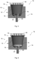
- Figure 1 is a schematic cross-sectional view of an example of a capsule according to the present invention.
- Figure 2 is a schematic cross-sectional view of another example of a capsule according to the present invention.
- Figure 3 is a schematic cross-sectional view of another example of a capsule according to the present invention.
- Figure 4 is a schematic cross-sectional view of a system comprising the capsule shown in Figure 1 and a beverage preparation machine.
- Figure 5 is a schematic cross-sectional view of a system comprising the capsule shown in Figure 2 and a beverage preparation machine.
- Figure 6 is a schematic cross-sectional view of a system comprising the capsule shown in Figure 3 and a beverage preparation machine.
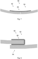
- Figure 7 is a schematic view of a seam of a cup-shaped body of a capsule according to the present invention.
- Figure 8 is a schematic view of a seam of a cup-shaped body of a capsule according to the present invention.
Detailed description
-
Within the figures, same components are referenced by the same reference numerals.
-
Figures 1 to 3 show schematic views of various examples of a capsule 10 according to the present invention. The embodiments of Figures 1 to 3 may be combined.
-
The
capsule 10 is configured for preparing a beverage, such as coffee, tea, hot chocolate, or the like, upon injecting liquid into the
capsule 10. The
capsule 10 is particularly suited to be used in connection with a capsule beverage preparation machine such as described in, for example,
EP 0 512 470 A1 or
EP 2 919 628 A1 . The
capsule 10 may be a single-serve capsule.
-
-
The body 12 has a top opening 16 and a top rim 18 surrounding said top opening 16. The body 12 is made of a first multilayer oxygen and/or moisture barrier material 20 comprising a paper or cardboard and an organic and/or inorganic barrier layer, the paper or cardboard having a grammage comprised between 40 and 450 g/m2 and a cellulose content higher than 30%, preferably higher than 50%, more preferably higher than 90%.
-
The capsule 10 further comprises a bottom closure 22 to close the body 12 and a sealing lid 24 connected to the body 12 via the top rim 18. In particular, the body 12 includes a bottom opening 26 which is closed by the bottom closure 22.
-
The capsule 10 may be manufactured by forming the side wall 14 of the cup-shaped body 12 by rolling the first multilayer oxygen and/or moisture barrier material into a cylindrical or conical shape. The top rim 18 may be formed on the cup-shaped body 12. The bottom closure 22 may be attached to the bottom opening 26 of the cup-shaped body 12. The lid 24 may be connected to the top rim 18 to close the top opening 16.
-
The
top rim 18 may form or include a
top flange 30. The
top flange 30 is configured such that the
capsule 10 can be clamped into a capsule holder of a capsule beverage preparation machine as described in, for example the aforementioned
EP 2 919 628 A1 .
-
The body 12 defines a receptacle 32 for holding beverage preparation ingredients. The side wall 14 delimits an opening or mouth of the body 12. The opening or mouth is closed by the sealing lid 24. The sealing lid 24 and the bottom closure 22 are sealingly connected to the side wall 14 such that the sealing lid 24, the side wall 14 and the bottom closure 22 together form a compartment for holding beverage preparation ingredients therein.
-
The
bottom closure 22 may have a convex or frusto-conical shape with a
central portion 34, which may be generally flat, concave or convex. The
bottom closure 22 is configured to be pierced by an opener of a beverage preparation machine as described in, for example the aforementioned
EP 2 919 628 A1 .
-
The bottom closure 22 may be made from a second multilayer oxygen and/or moisture barrier material comprising a paper or cardboard and an organic and/or inorganic barrier layer. The paper or cardboard may have a grammage comprised between 40 and 450 g/m2 and a cellulose content higher than 30%, preferably higher than 50%, more preferably higher than 90%. The second material may be the same or different from the first material.
-
Within the frame of the present invention, the material(s) may contain, in addition to a first cardboard (or "paperboard") layer having a grammage between 120 g/m2 and 450 g/m2, an additional paper layer having a grammage comprised between 40 and 120 g/m2. In this case the two layers of paperboard and paper are preferably joined together with an intermediate adhesive layer. In this case, at least one of an organic and/or organic layer is added to the material in order to provide barrier properties against, receptively, oxygen and/or moisture transfer through said material.
-
The sealing
lid 24 is configured to be pierced by a piercing plate, such as a pyramid plate which is usually used in the above-mentioned beverage preparation machine. The piercing plate, such as a pyramid plate, is configured for creating a plurality of openings in the sealing
lid 24. Pyramid plates include a plurality of reliefs and recessed (pyramid-like) elements. These elements are configured to tear open the sealing
lid 24 for creating a plurality of openings in the sealing
lid 24 under the effect of rising pressure of the liquid injected into the
capsule 10. Through these openings in the sealing
lid 24 the beverage is dispensed. Pyramid plates are described, for example, in
EP 0 512 470 A1 .
-
In the specific embodiment shown in Figure 1 , the cup-shaped body 12, in particular a bottom rim or bottom flange thereof, folds around the bottom closure 22, in particular around a radially outer peripheral wall 36 of the bottom closure 22. The radially outer peripheral wall 36 may be cylindrical or frusto-conical. The radially outer peripheral wall 36 forms a radially outermost portion of the bottom closure 22 in the specific example shown in Figure 1 .
-
In the specific embodiment shown in Figure 1 , the cup-shaped body 12 folds around the bottom closure 22 in a U shape. The U-shape is open towards a top end of the capsule 10, as visible in the cross section shown in Figure 1 .
-
In the specific embodiment shown in Figure 1 , the cup-shaped body 12 folds radially inward around the radially outer peripheral wall 36.
-
The cup-shaped body 12 folding around the bottom closure 22 forms a seal between the cup-shaped body 12 and the bottom closure 22. The seal is liquid and/or gas tight.
-
As shown in the example in Figure 1 , the bottom closure 22 includes a peripheral recess 40. The peripheral recess 40 may be circular.
-
As shown in the example in Figure 1 , the peripheral recess 40 is arranged in a radially outer portion of the bottom closure 22. The radially outer peripheral wall 36 delimits the peripheral recess 40. The cup-shaped body 12 extends into the peripheral recess 40.
-
As shown in the example in Figure 1 , the bottom closure 22 comprises a radially inner peripheral wall 42 which may be cylindrical or frusto-conical.
-
As shown in the example in Figure 1 , the radially inner peripheral wall 42 delimits an inner recess 44 of the bottom closure 22. The radially inner peripheral wall 42 extends around the inner recess 44.
-
The radially inner peripheral wall 42 extends around a bottom wall 46 of the bottom closure 22. In particular, the bottom wall 46 extends perpendicularly to a longitudinal axis L of the capsule 10. The radially inner peripheral wall 42, the bottom wall 46, and the cup-shaped body 12 together delimit an inner cavity of the capsule 10.
-
In the example of Figure 2 , the side wall 14 has a main section 48 and a bottom rim 50 (which may also be referred to as a bottom flange in the context of the present invention). The main section 48 may have a cylindrical shape and the bottom rim 50 may have a frusto-conical shape.
-
Alternatively, the main section 48 may have a first frusto-conical shape and the bottom rim 50 may have a second frusto-conical shape. A cone angle α2 of the second frusto-conical shape is larger than a cone angle α1 of the first frusto-conical shape, as shown in Figure 2 .
-
In the specific embodiment shown in Figure 2 , the bottom rim 50 extends radially inward and/or towards a longitudinal axis L of the capsule 10 from the main section.
-
In the specific embodiment shown in Figure 2 , the bottom closure 22 has a frusto-conical peripheral wall 54 and a bottom wall 56 closing a bottom end of said frusto-conical peripheral wall 54. An angle β between the frusto-conical peripheral wall 54 and the bottom wall 56 may be at least 120°, preferably at least 130°, more preferably at least 145°. The angle β is measured in a cross section of the capsule 10 taken along the capsule's longitudinal axis L.
-
Additionally, or alternatively, the angle β between the frusto-conical peripheral wall 54 and the bottom wall 56 may be 120° or less, preferably 110° or less, more preferably 100° or less, as shown in the specific embodiment of Figure 3 . As shown in Figure 3 , a bottom rim may be dispensed of in this case.
-
The top rim 18 may be provided and/or defined by the side wall 14 in the embodiments of Figures 1 and 2 . As discussed, such top rim 18 may be formed by bending, e.g. bending after rolling the first material forming the side wall 14.
-
Alternatively, shown in Figure 3 , the sealing lid 24 may be attached directly to the cup-shaped body 12, in particular to a main portion of the side wall 14. As shown in Figure 3 , no top rim is required in this case. Accordingly, the capsule 10 of Figure 3 does neither have a top rim nor a bottom rim. The skilled reader will understand, however, that one such top rim or bottom rim may be provided, as desired (e.g., any of the top or bottom rims as described with reference to Figure 1 and 2 ).
-
The sealing lid 24 may be a non-planar and/or pre-shaped component. For example, as shown in Figure 3, the sealing lid 24 may have a recessed center portion 25 that is configured to be inserted into the cup-shaped body 12. This may facilitate attachment of the sealing lid 24 to the body 12. The cross section of the sealing lid 24 may be described as hat-shaped.
-
Preferably, the sealing lid 24 is attached to an inner surface of the side wall 14. This is believed to provide for an easier assembly and sealing.
-
Alternatively, the sealing lid 24 could be attached to an outer surface of the side wall 14. For this purpose, the sealing lid 24 could be provided with a protruding center portion or a U-shaped groove (not shown).
-
As further shown in Figure 3 , at least one separate component 70 may be attached, e.g., adhesively, to the sealing lid 24. The component 70 may be configured to provide a circumferentially outer portion of the sealing lid 24 with increased rigidity and/or thickness. This may be helpful for ensuring that an ejection mechanism of known beverage preparation machines can adequately engage the capsule 10 via the component 70 and eject the capsule 10 from the machine after extraction.
-
The component 70 may be ring-shaped.
-
The component 70 may only be connected to the side wall 14 and/or the cup-shaped body 12 via the sealing lid 12..
-
Figure 4 shows a schematic cross-sectional view of a system 72 comprising the capsule 10 shown in Figure 1 and a beverage preparation machine 74 (shown only partially in Figure 4 ) which comprises a plurality of needles, blades or puncture elements 76. The blades 76 may be provided as part of an opener arranged within a brewing chamber of the beverage preparation machine 74. The opener may comprise three blades 76.
-
The blades 76 are configured to pierce through the bottom closure 22, as shown in Figure 4 . Preferably, the blades 76 are configured to not pierce through the side wall 14 of the cup-shaped body 12. In particular, the side wall 14 of the cup-shaped body 12 may remain free of any openings during the entire beverage extraction process, at least any openings which were not present in the side wall 14 prior to the beverage extraction process. In other words, the capsule 10 may be dimensioned and/or constructed such that the blades 76 only pierce through the bottom closure 22.
-
The beverage preparation machine 74 further comprises a lid opening plate 78, such as a pyramid plate, configured to open the sealing lid 24, preferably by rising pressure within the capsule 10. A brewed beverage is configured to flow out of the capsule 10 through the lid 24 and/or through the lid opening plate 78 to an outlet of the machine 74. For instance, a liquid may be guided through an inlet 80 into the capsule 10, preferably via opening in the bottom closure 22 created by the blades 76. The lid opening plate 78 may include one or more, preferably a plurality of, pyramid-shaped elements 82. The lid opening plate 78, e.g. the pyramid-shaped elements 82, may be configured to at least partially tear open the sealing lid 24 to provide one or more openings in the sealing lid 24 for liquid to flow through, e.g., out of or into the capsule 10. For example, the lid opening plate 78 may be configured to at least partially tear open the sealing lid 24 when raising pressure within the capsule 10 presses the sealing lid 24 against the lid opening plate 78. The pyramid-shaped elements 82 may alternatively have a variety of other shapes, e.g., a cylindrical shape.
-
Similarly, Figures 5 and 6 show systems 72 comprising the capsule 10 shown in Figures 2 and 3 , respectively, and the beverage preparation machine 74.
-
Figure 7 shows a schematic view of a seam 60 of the cup-shaped body 12 of the capsule 10. A first peripheral end 62 of the material 20 of the body 12 is sealingly connected to a second peripheral end 64 of the material 20 of the body 12 along the seam 60 of the cup-shaped body 12. The seam 60 extends axially along the side wall 14.
-
In the specific embodiment shown in Figure 7 , the first peripheral end 62 does not overlap the second peripheral end 64 along the seam 60. Alternatively, the first peripheral end 62 may overlap the second peripheral end 64 along the seam 60, as shown in the specific embodiment shown in Figure 8 .
-
A sealing strip 66 sealingly connects the first peripheral end 62 to the second peripheral end 64. The sealing strip 66 extends at least partially along the inside of the cup-shaped body 12, e.g., at least partially in the receptacle 32. Alternatively, or additionally, the sealing strip 66 may extend at least partially along the outside of the cup-shaped body 12, e.g., at least partially outside of the receptacle 32.
-
In the specific embodiment shown in Figure 8 , the sealing strip 66 extends around the first peripheral end 62 and is attached to the second peripheral end 64. Alternatively, or additionally, the sealing strip 66 may extend around the second peripheral end 64 and may be attached to the second peripheral end 64.