EP4556383A1 - Filling system for supplying pourable product into a tube of packaging material for the production of packages containing such pourable product - Google Patents
Filling system for supplying pourable product into a tube of packaging material for the production of packages containing such pourable product Download PDFInfo
- Publication number
- EP4556383A1 EP4556383A1 EP24192756.5A EP24192756A EP4556383A1 EP 4556383 A1 EP4556383 A1 EP 4556383A1 EP 24192756 A EP24192756 A EP 24192756A EP 4556383 A1 EP4556383 A1 EP 4556383A1
- Authority
- EP
- European Patent Office
- Prior art keywords
- delimiting element
- tube
- filling system
- coupling portion
- axial
- Prior art date
- Legal status (The legal status is an assumption and is not a legal conclusion. Google has not performed a legal analysis and makes no representation as to the accuracy of the status listed.)
- Pending
Links
Images


Classifications
-
- B—PERFORMING OPERATIONS; TRANSPORTING
- B65—CONVEYING; PACKING; STORING; HANDLING THIN OR FILAMENTARY MATERIAL
- B65B—MACHINES, APPARATUS OR DEVICES FOR, OR METHODS OF, PACKAGING ARTICLES OR MATERIALS; UNPACKING
- B65B9/00—Enclosing successive articles, or quantities of material, e.g. liquids or semiliquids, in flat, folded, or tubular webs of flexible sheet material; Subdividing filled flexible tubes to form packages
- B65B9/10—Enclosing successive articles, or quantities of material, in preformed tubular webs, or in webs formed into tubes around filling nozzles, e.g. extruded tubular webs
- B65B9/20—Enclosing successive articles, or quantities of material, in preformed tubular webs, or in webs formed into tubes around filling nozzles, e.g. extruded tubular webs the webs being formed into tubes in situ around the filling nozzles
- B65B9/2049—Package shaping devices acting on filled tubes prior to sealing the filling opening
-
- B—PERFORMING OPERATIONS; TRANSPORTING
- B65—CONVEYING; PACKING; STORING; HANDLING THIN OR FILAMENTARY MATERIAL
- B65B—MACHINES, APPARATUS OR DEVICES FOR, OR METHODS OF, PACKAGING ARTICLES OR MATERIALS; UNPACKING
- B65B31/00—Packaging articles or materials under special atmospheric or gaseous conditions; Adding propellants to aerosol containers
- B65B31/04—Evacuating, pressurising or gasifying filled containers or wrappers by means of nozzles through which air or other gas, e.g. an inert gas, is withdrawn or supplied
- B65B31/044—Evacuating, pressurising or gasifying filled containers or wrappers by means of nozzles through which air or other gas, e.g. an inert gas, is withdrawn or supplied the nozzles being combined with a filling device
- B65B31/045—Evacuating, pressurising or gasifying filled containers or wrappers by means of nozzles through which air or other gas, e.g. an inert gas, is withdrawn or supplied the nozzles being combined with a filling device of Vertical Form-Fill-Seal [VFFS] machines
-
- B—PERFORMING OPERATIONS; TRANSPORTING
- B65—CONVEYING; PACKING; STORING; HANDLING THIN OR FILAMENTARY MATERIAL
- B65B—MACHINES, APPARATUS OR DEVICES FOR, OR METHODS OF, PACKAGING ARTICLES OR MATERIALS; UNPACKING
- B65B59/00—Arrangements to enable machines to handle articles of different sizes, to produce packages of different sizes, to vary the contents of packages, to handle different types of packaging material, or to give access for cleaning or maintenance purposes
- B65B59/04—Machines constructed with readily-detachable units or assemblies, e.g. to facilitate maintenance
-
- B—PERFORMING OPERATIONS; TRANSPORTING
- B65—CONVEYING; PACKING; STORING; HANDLING THIN OR FILAMENTARY MATERIAL
- B65B—MACHINES, APPARATUS OR DEVICES FOR, OR METHODS OF, PACKAGING ARTICLES OR MATERIALS; UNPACKING
- B65B9/00—Enclosing successive articles, or quantities of material, e.g. liquids or semiliquids, in flat, folded, or tubular webs of flexible sheet material; Subdividing filled flexible tubes to form packages
- B65B9/10—Enclosing successive articles, or quantities of material, in preformed tubular webs, or in webs formed into tubes around filling nozzles, e.g. extruded tubular webs
- B65B9/20—Enclosing successive articles, or quantities of material, in preformed tubular webs, or in webs formed into tubes around filling nozzles, e.g. extruded tubular webs the webs being formed into tubes in situ around the filling nozzles
- B65B9/207—Enclosing successive articles, or quantities of material, in preformed tubular webs, or in webs formed into tubes around filling nozzles, e.g. extruded tubular webs the webs being formed into tubes in situ around the filling nozzles the web advancing continuously
Definitions
- the present invention relates to a filling system for filling a tube of packaging material for the production of packages containing a pourable product, preferably a pourable food product.
- the present invention refers, without loss of generality, to a filling system which is part of a packaging apparatus configured to produce sealed and folded packages containing a pourable product.
- pourable food products such as fruit juice, UHT (ultra-high temperature-treated) milk, wine, tomato sauce, etc.
- UHT ultra-high temperature-treated milk
- wine tomato sauce
- etc. are sold in packages made of sterilized packaging material.
- a typical example is the parallelepiped-shaped package for pourable food products known as Tetra Brik Aseptic (registered trademark), which is made by folding and sealing a laminated web of packaging material.
- the packaging material has a multilayer structure comprising a base layer, e.g. made of paper, covered on both sides with layers of heat-seal plastic material, e.g. polyethylene.
- the packaging material also comprises a layer of oxygen-barrier material, e.g. an aluminum foil, which is superimposed on a layer of heat-seal plastic material, and is in turn covered with another layer of heat-seal plastic material forming the inner face of the package eventually contacting the food product.
- a layer of oxygen-barrier material e.g. an aluminum foil
- Packages of this sort are normally produced on fully automatic packaging apparatuses, which form and fill the packages starting from a multilayer web of packaging material.
- a continuous tube is formed from the web of packaging material which is initially wound in a reel and fed through a plurality of unwinding rollers.
- the web of packaging material is typically sterilized in the packaging apparatus, e.g. by applying a chemical sterilizing agent, such as hydrogen peroxide solution, which, once sterilization is completed, is removed from the surfaces of the packaging material, e.g. evaporated by heating.
- a chemical sterilizing agent such as hydrogen peroxide solution
- the tube In order to perform the package forming operations, the tube is continuously fed along a first direction, normally a straight vertical direction, is filled with the sterilized food product from above and is formed, sealed and subsequently cut along equally spaced transversal cross-sections extending along a second direction, normally a direction orthogonal to the first direction.
- a typical packaging apparatus comprises a plurality of forming, sealing and cutting assemblies, each one advanced along an operative path parallel to the first direction.
- the forming, sealing and cutting assemblies start interacting with the tube at a pre-set position along the operative path and follow the tube advancing along the first direction so as to shape, to transversally seal and to cut the tube so as to obtain single pillow packs.
- a packaging apparatus of the above type comprises a filling system configured to fill the tube with the pourable product, while the tube is continuously formed, sealed and advanced along said first direction.
- the filling system comprises a filling pipe which is inserted in and surrounded by the tube in formation, and which delivers the pourable product into the tube, so that a column of pourable product is defined and maintained within the tube.
- a filling pipe which is inserted in and surrounded by the tube in formation, and which delivers the pourable product into the tube, so that a column of pourable product is defined and maintained within the tube.
- Such pipe has a longitudinal axis usually arranged parallel to said first direction.
- the column of pourable product provides for the required hydrostatic pressure.
- such column of pourable product can have a significant extension, for example extending up to 2000mm upwards from the aforementioned pre-set position.
- the forming, sealing and cutting devices interact with the tube, but the column of pourable product has not yet reached the nominal extension required for defining the nominal hydrostatic pressure. As a result, a certain number of irregularly formed packs is produced during the starting transient, which packs have to be discarded.
- EP-A-3456638 discloses a packaging apparatus of the above type and comprising:
- the delimiting plate has a central passage through which the filling pipe extends.
- the feeding duct is configured to supply the compressed air into the second space, thereby controlling the pressure therein to be greater than the pressure within the sterile environment.
- the aforementioned pressure can be controlled, and in particular increased, so that the extension of the column of pourable product can be reduced while obtaining the same value of hydrostatic pressure.
- the number of irregularly formed packages produced during the aforementioned starting transient can be reduced, since it is possible to reach the hydrostatic pressure faster.
- WO-A-2020229068 discloses a packaging apparatus of the above type, wherein the delimiting plate is movable parallel to the first direction so as to "float" between an abutment portion of the feeding duct and a support member accommodated in the tube and fixed to the filling pipe in a position below the delimiting plate itself.
- This floating movement enables an adaptation of the filling system to the inherent fluctuations occurring during the packaging process.
- the Applicant has observed that the filling systems of the known type are still open to further improvement, in particular as per the repeatability of the shape and weight of the packages produced by the packaging apparatus, as per the ease of assembling thereof and as per the ease of maintenance thereof.
- number 1 indicates as a whole a non-limiting example of a packaging apparatus for producing a plurality of packages 2 containing a pourable product, preferably a pourable food product such as pasteurized or UHT milk, water, fruit juice, wine, peas, beans, etc.
- a pourable food product such as pasteurized or UHT milk, water, fruit juice, wine, peas, beans, etc.
- packaging apparatus 1 is configured to form, seal and fold packages 2 starting from a web 4 of packaging material, which is initially wound in a reel 4a, and then folded into a tube 3 of packaging material, as explained below.
- the packaging material has a multilayer structure (not shown), and comprises a layer of fibrous material, e.g. paper, covered on both sides with respective layers of heat-seal plastic material, e.g. polyethylene.
- a layer of fibrous material e.g. paper
- heat-seal plastic material e.g. polyethylene
- the packaging material also comprises a layer of gas-and-light barrier material, e.g. aluminum foil or ethylene vinyl alcohol (EVOH) film, which is superimposed on a layer of heat-seal plastic material, and is in turn covered with another layer of heat-seal plastic material, the latter forming the inner face of package 2 eventually contacting the pourable product.
- gas-and-light barrier material e.g. aluminum foil or ethylene vinyl alcohol (EVOH) film
- the packaging material is initially provided in the form of a web 4.
- the packaging apparatus 1 comprises:
- forming and sealing unit 6 has an axis X along which tube 3 is fed, in use.
- Axis X is parallel to a straight direction, which preferably is a straight vertical direction.
- tube 3 is fed along axis X, downwards, and while being filled from above is formed and sealed by forming and sealing unit 6, according to a manner known and not described in detail.
- tube 3 is drawn (downwards) along axis X by forming and sealing unit 6 in a known manner.
- Packaging apparatus 1 may further comprise a folding unit (known per se and not shown) for folding the pillow packs 2a, thereby obtaining packages 2, according to a manner known and not described in detail.
- a folding unit known per se and not shown
- packaging apparatus 1 is configured to form and seal a plurality of pillow packs 2a containing the pourable product starting from web 4 and tube 3 and then to fold the pillow packs 2a for obtaining the aforementioned formed, sealed and folded packages 2 containing the pourable product.
- filling system 7 comprises a product filling pipe 10 extending along a longitudinal axis A and designed to be arranged (at least partially) within tube 3, i.e. arranged in use within tube 3, so that tube 3 surrounds filling pipe 10, and configured to feed pourable product within tube 3.
- filling pipe 10 is in fluid connection or is controllable to be in fluid connection with a pourable product storage tank (not shown and known as such), which is adapted to store/provide for the pourable product, in particular the sterilized and/or sterile-processed pourable food product, to be packaged.
- a pourable product storage tank (not shown and known as such), which is adapted to store/provide for the pourable product, in particular the sterilized and/or sterile-processed pourable food product, to be packaged.
- filling pipe 10 is arranged coaxial with axis X, i.e. with tube 3.
- Filling system 7 further comprises a gas feeding duct 11 designed to be arranged (at least partially) within tube 3, i.e. arranged in use within tube 3, and configured to supply compressed gas into tube 3, in particular compressed sterile gas withdrawn from isolation chamber 8.
- a gas feeding duct 11 designed to be arranged (at least partially) within tube 3, i.e. arranged in use within tube 3, and configured to supply compressed gas into tube 3, in particular compressed sterile gas withdrawn from isolation chamber 8.
- feeding duct 11 extends parallel to axis A. More preferably, feeding duct 11 has a longitudinal axis B and is arranged coaxial to filling pipe 10.
- feeding duct 11 surrounds filling pipe 10, so that an annular flow channel 12 for the compressed gas is delimited between an outer (lateral) surface 10a of filling pipe 10 and an inner (lateral) surface 11a of feeding duct 11.
- Filling system 7 further comprises a delimiting element, and in particular defined by a flange or delimiting element 13 designed to be arranged within tube 3, i.e. arranged in use within tube 3, for dividing tube 3 in a first inner compartment or space 3a and a second inner compartment or space 3b arranged downstream of first space 3a with respect to the tube (downward) advancement direction along axis X.
- a delimiting element and in particular defined by a flange or delimiting element 13 designed to be arranged within tube 3, i.e. arranged in use within tube 3, for dividing tube 3 in a first inner compartment or space 3a and a second inner compartment or space 3b arranged downstream of first space 3a with respect to the tube (downward) advancement direction along axis X.
- filling pipe 10 is configured to supply the pourable product into the second space 3b and feeding duct 11 is configured to supply the compressed gas into the second space 3b, so that a gas pressure within the second space 3b is higher than the gas pressure within the first space 3a.
- delimiting element 13 does not contact tube 3, so that first space 3a is not fluid-tightly separated from second space 3b.
- a relatively small aperture is defined between delimiting element 13 and tube 3, so as to allow a fast advancement of tube 3 without contacting delimiting element 13, which would be detrimental to the wear of tube 3 itself.
- delimiting element 13 has a central axis C and a through hole 14 laterally delimited by an inner rim wall 14a which extends about axis C.
- through hole 14 is arranged coaxial to axis C ( Figures 4 and 6 ).
- delimiting element 13 is mounted coaxial with feeding duct 11 (according to a manner described below) and through hole 14 is axially engaged by filling pipe 10, as depicted in Figures 2 and 3 .
- axes A, B and C are arranged coaxial to one another.
- Feeding duct 11 comprises a coupling portion 15 arranged at an axial end 11b thereof, and in particular integrally fixed to end 11b.
- end 11b may be a free end of feeding duct 11.
- coupling portion 15 defines a continuation of free end 11b.
- Coupling portion 15 has a plurality of holding members 16.
- delimiting element 13 is coupled to feeding duct 11 in a releasable manner via the holding members 16.
- coupling portion 16 includes a first abutment surface 15a and a second abutment surface 15b which faces, and in particular axially faces, first abutment surface 15a and is defined by the holding members 16.
- second abutment surface 15b is discontinued and defined by the set of the holding members 16.
- first abutment surface 15a and second abutment surface 15b are transversal, and in particular orthogonal, to axis A (or to the axial direction).
- delimiting element 13 is releasably fitted in interlocking manner to coupling portion 15 between the first abutment surface 15a and the second abutment surface 15b.
- delimiting element 13 is substantially axially fixed, in a releasable manner, between the first abutment surface 15a and the holding members 16.
- delimiting element 13 may be axially locked in a releasable manner, between the first abutment surface 15a and the holding members 16.
- delimiting element 13 may be configured to slightly move or oscillate, in the axial direction, between the first abutment surface 15a and the holding members 16.
- interlocking indicates a mechanical connection or coupling so that the axial motion or operation of any part in the axial direction is at least partially constrained by another part.
- delimiting element 13 and feeding duct 11 define two separate and distinct components of filling system 7, with solution of continuity.
- axis B defines a central axis for coupling portion 15.
- Holding members 16 extend axially and are angularly distributed about axis B.
- coupling portion 15 is defined by a substantially tubular body with a radial rim protruding radially outwards from an end portion thereof.
- the holding members 16 protrude axially from such radial rim.
- the first abutment surface 15a is defined by a (lower) surface of the radial rim surrounding the portions of the radial rim from which the holding members 16 protrude.
- delimiting element 13 is configured to be mounted coaxial with coupling portion 15.
- delimiting element 13 has a first wall 13a ( Figures 3 and 4 ) and a second wall 13b ( Figures 3 and 6 ) which is opposite to first wall 13a, i.e. which faces towards a direction opposite to the direction towards which first wall 13a faces.
- First wall 13a abuts against first abutment surface 15a and second wall 13b rests on the holding members 16, i.e. on the second abutment surface 15b ( Figure 3 ).
- inner wall 14a of delimiting element 13 has a plurality of radial slots 17 obtained thereon, which are angularly distributed about axis C and are radially open towards such axis C.
- Each radial slot 17 is configured to be axially engaged by a respective holding member 16 for defining a mounting/dismounting of delimiting element 13 to/from coupling portion 15.
- each radial slot 17 is configured to be axially engaged by a respective holding member 16 i.e. during a mounting/dismounting of delimiting element 13 to/from coupling portion 15.
- delimiting element 13 is configured to assume, relatively to coupling portion 15:
- filling system 7 is configured such that the mounting position corresponds to a first angular position of delimiting element 13 and the operative position corresponds to a second angular position of delimiting element 13, relative to axis A.
- delimiting element 13 is adapted to be rotated about axis C (and hence with about axes A and B, and in particular with respect to coupling portion 15) in order to selectively assume the mounting position or the operative position.
- the coupling between delimiting element 13 and coupling portion 15 defines a sort of bayonet coupling, whereby the decoupling position and the coupling position are angularly separated from one another.
- filling system 7 it is possible to reduce the hydrostatic pressure fluctuations within the second space 3b, as delimiting element 13 is axially fixed and locked, and therefore to increase the repeatability of the shape and weight of the packages 2. At the same time, the assembling of filling system 7 is not only not hindered but also eased, as well as the maintenance thereof.
- each holding member 16 is substantially L-shaped and includes an axial portion 18 axially protruding from the first abutment surface 15a and a radial portion 19 radially extending from the axial portion 18 in a cantilevered manner.
- the set of radial portions 19 defines the second abutment surface 15b, which is therefore discontinued around axis B.
- second wall 13b rests on the radial portion 19 of each holding member 16.
- each radial portion 19 is substantially flat (along the radial direction) so as to allow a movement of delimiting element 13 along the radial direction, with respect to axis A or B.
- holding members 16 are angularly distributed about axis B.
- coupling portion 15 includes three holding members 16 angularly spaced from one another by an angle of 120°.
- delimiting element 13 provides for a better self-centering of delimiting element 13, which cannot be obtained if delimiting element 13 is integrally fixed to feeding duct 11.
- the filling system 7 provides for an optimal compromise between hydrostatic pressure stability during operation (ensured by the axial interlocking of delimiting element 13) and flexibility for self-centering of delimiting element 13 (ensured by the absence of radial constraints on delimiting element 13).
- filling system 7 comprises a support member 20 fixed to filling pipe 10, in particular integrally fixed thereon, and having an axial resting surface 21.
- support member 20 in mounted coaxial to axis A and is hollow so as to be axially engaged by filling pipe 10.
- resting surface 21 faces delimiting element 13, and in particular second wall 13b thereof.
- delimiting element 13 when delimiting element 13 is in the operative position, delimiting element 13 rests on resting surface 21 and is axially interposed between support member 20 and coupling portion 15, so that an inclination of delimiting element 13 with respect to the radial plane relative to axis A is prevented.
- support member 20 further decreases the possibility of an axial oscillation of delimiting element 13, thereby further reducing the possibility of hydrostatic pressure fluctuations.
- support member 20 is axially fixed to filling pipe 10 by means of a quick-fitting coupling member 25.
- a bayonet coupling 26 is provided ( Figure 5 ).
- support member 21 has an axial protrusion 22 axially extending from resting surface 21, and delimiting element 13 has an axial receiving seat 23 adapted to accommodate axial protrusion 22 for preventing a rotation of delimiting element 13 about axis A.
- receiving seat 23 is configured to be engaged by axial protrusion 22 when delimiting element 13 is in said operative position, for defining an anti-rotation device thereof.
- delimiting element 13 includes an axial passage 24 ( Figures 6 and 7 ) located at an outer peripheral portion thereof and configured to be repeatedly engaged by an inner portion of a sequence of closure structures (known per se and not shown) pre-applied on tube 3, so as to allow the free passage of the pre-applied closure structures through delimiting element 13 itself.
- each one of the aforementioned closure structures is defined by a neck of a closure (made of plastic material) adapted to receive a cap (made of plastic material as well), which neck is pre-applied by molding process on the web of packaging material prior to the formation of tube 3, according to a manner known and not described in detail.
- passage 24 is angularly fixed with respect to axis A by means of engagement of axial protrusion 22 in receiving seat 23, i.e. by means of the aforementioned anti-rotation device.
- filling system 7 reduces the hydrostatic pressure fluctuations within the second space 3b, as delimiting element 13 is axially fixed and locked, and therefore allows to increase the repeatability of the shape and weight of the packages 2.
- the assembling and disassembling of filling system 7 is largely eased, as well as the maintenance thereof, due to the releasable coupling of delimiting element 13 with coupling portion 15.
- delimiting element 13 self-centering of delimiting element 13 is not hindered compared to the cases in which delimiting element 13 is integrally fixed in the axial and radial direction to feeding duct 11. Hence, filling system 7 enables to reach an optimal compromise between axial locking and radial centering of delimiting element 13.
Landscapes
- Engineering & Computer Science (AREA)
- Mechanical Engineering (AREA)
- Chemical & Material Sciences (AREA)
- Dispersion Chemistry (AREA)
- Basic Packing Technique (AREA)
- Containers And Plastic Fillers For Packaging (AREA)
Abstract
There is described a filling system (7) configured for supplying pourable product into a tube (3) of packaging material for the production of packages (2), the filling system (7) comprises: a plate (13) arranged within the tube (3) for dividing the tube (3) in a first inner space (3a) and a second inner space (3b); a product filling pipe (10) extending along a longitudinal axis (A), designed to be arranged within the tube (3) and configured to supply pourable product into the second inner space (3b); a gas feeding duct (11) designed to be arranged within the tube (3) and configured to supply compressed gas into the second inner space (3b) so that a gas pressure within the second inner space (3b) is higher than the gas pressure within the first inner space (3a); the gas feeding duct (11) comprises a coupling portion (15) arranged at an end (11b) thereof and having a plurality of holding members (16); the plate (13) is coupled to the gas feeding duct (11) in a removable manner via the holding members (16).
Description
- The present invention relates to a filling system for filling a tube of packaging material for the production of packages containing a pourable product, preferably a pourable food product.
- In particular, the present invention refers, without loss of generality, to a filling system which is part of a packaging apparatus configured to produce sealed and folded packages containing a pourable product.
- As it is generally known, many pourable food products, such as fruit juice, UHT (ultra-high temperature-treated) milk, wine, tomato sauce, etc., are sold in packages made of sterilized packaging material.
- A typical example is the parallelepiped-shaped package for pourable food products known as Tetra Brik Aseptic (registered trademark), which is made by folding and sealing a laminated web of packaging material. The packaging material has a multilayer structure comprising a base layer, e.g. made of paper, covered on both sides with layers of heat-seal plastic material, e.g. polyethylene.
- In the case of aseptic packages for long-storage products, such as UHT milk, the packaging material also comprises a layer of oxygen-barrier material, e.g. an aluminum foil, which is superimposed on a layer of heat-seal plastic material, and is in turn covered with another layer of heat-seal plastic material forming the inner face of the package eventually contacting the food product.
- Packages of this sort are normally produced on fully automatic packaging apparatuses, which form and fill the packages starting from a multilayer web of packaging material.
- In particular, in such packaging apparatuses a continuous tube is formed from the web of packaging material which is initially wound in a reel and fed through a plurality of unwinding rollers. The web of packaging material is typically sterilized in the packaging apparatus, e.g. by applying a chemical sterilizing agent, such as hydrogen peroxide solution, which, once sterilization is completed, is removed from the surfaces of the packaging material, e.g. evaporated by heating. The web so sterilized is then maintained in a closed, sterile environment, and, while advanced by the aforementioned unwinding rollers, is folded to form the tube by means of a known web folding unit and then sealed longitudinally.
- In order to perform the package forming operations, the tube is continuously fed along a first direction, normally a straight vertical direction, is filled with the sterilized food product from above and is formed, sealed and subsequently cut along equally spaced transversal cross-sections extending along a second direction, normally a direction orthogonal to the first direction.
- In detail, a typical packaging apparatus comprises a plurality of forming, sealing and cutting assemblies, each one advanced along an operative path parallel to the first direction. During such advancement, the forming, sealing and cutting assemblies start interacting with the tube at a pre-set position along the operative path and follow the tube advancing along the first direction so as to shape, to transversally seal and to cut the tube so as to obtain single pillow packs.
- Typically, a packaging apparatus of the above type comprises a filling system configured to fill the tube with the pourable product, while the tube is continuously formed, sealed and advanced along said first direction.
- In detail, the filling system comprises a filling pipe which is inserted in and surrounded by the tube in formation, and which delivers the pourable product into the tube, so that a column of pourable product is defined and maintained within the tube. Such pipe has a longitudinal axis usually arranged parallel to said first direction.
- In order to correctly form the pillow packs, and therefore in order to obtain finished fully-folded packages which reproduce the nominal desired configuration, it is required that the hydrostatic pressure provided by the pourable product within the tube is sufficiently high as otherwise irregularly shaped packages would be obtained.
- As it is known, the column of pourable product provides for the required hydrostatic pressure.
- Depending on the package format and on the desired production speed, such column of pourable product can have a significant extension, for example extending up to 2000mm upwards from the aforementioned pre-set position. This means that the tube must have an extension so as to provide for the required column of pourable product within the tube, and in turn that the packaging apparatus must have a size so as to accommodate the tube.
- Furthermore, during the starting transient of the packaging apparatus, the forming, sealing and cutting devices interact with the tube, but the column of pourable product has not yet reached the nominal extension required for defining the nominal hydrostatic pressure. As a result, a certain number of irregularly formed packs is produced during the starting transient, which packs have to be discarded.
- In order to overcome the aforementioned drawbacks, various solutions have been proposed.
-
EP-A-3456638 discloses a packaging apparatus of the above type and comprising: - a gas feeding duct arranged coaxially with the product filling pipe, so that an annular channel is delimited between the outer surface of the filling pipe and the inner surface of the gas feeding duct, which feeding duct is designed to feed compressed air through the annular channel and towards the column of pourable product; and
- a delimiting element or flange or plate integrally fixed to the gas feeding duct, arranged within the tube and dividing the tube in a first space or compartment being in fluidic connection with the sterile environment and a second space or compartment being arranged downstream of the first space.
- The delimiting plate has a central passage through which the filling pipe extends.
- In detail, the feeding duct is configured to supply the compressed air into the second space, thereby controlling the pressure therein to be greater than the pressure within the sterile environment.
- In this way, the aforementioned pressure can be controlled, and in particular increased, so that the extension of the column of pourable product can be reduced while obtaining the same value of hydrostatic pressure.
- Moreover, the number of irregularly formed packages produced during the aforementioned starting transient can be reduced, since it is possible to reach the hydrostatic pressure faster.
-
WO-A-2020229068 discloses a packaging apparatus of the above type, wherein the delimiting plate is movable parallel to the first direction so as to "float" between an abutment portion of the feeding duct and a support member accommodated in the tube and fixed to the filling pipe in a position below the delimiting plate itself. - This floating movement enables an adaptation of the filling system to the inherent fluctuations occurring during the packaging process.
- Although being structurally and functionally valid, the Applicant has observed that the filling systems of the known type are still open to further improvement, in particular as per the repeatability of the shape and weight of the packages produced by the packaging apparatus, as per the ease of assembling thereof and as per the ease of maintenance thereof.
- It is therefore an object of the present invention to provide a filling system configured for filling a tube of packaging material for the production of packages containing a pourable product, which is designed to overcome at least one of the above-mentioned drawbacks in a straightforward and low-cost manner.
- This object is achieved by a filling system as claimed in the appended independent claim 1. Preferred embodiments of the present invention are laid down in the appended dependent claims.
- A non-limiting embodiment of the present invention will be described by way of example with reference to the accompanying drawings, in which:
-
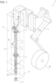
Figure 1 is a schematic perspective view, with parts removed for clarity, of a packaging apparatus including a filling system according to the present invention; -
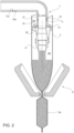
Figure 2 is a larger-scale, partially sectioned schematic lateral view, with parts removed for clarity, of details of the packaging apparatus and of the filling system according to the present invention; -
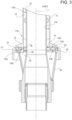
Figure 3 is a larger-scale, sectioned view, with parts removed for clarity, of details of the filling system ofFigure 2 ; -
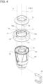
Figure 4 is a perspective exploded view, with parts removed for clarity, of the filling system according to the present invention; -
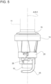
Figure 5 is a lateral view of the filling system ofFigure 4 in an assembled configuration; -
Figure 6 is a perspective exploded view from below, with parts removed for clarity, of parts of the filling system according to the present invention; and -
Figure 7 is a perspective view from below of parts of the filling system ofFigure 6 . - With reference to
Figure 1 , number 1 indicates as a whole a non-limiting example of a packaging apparatus for producing a plurality ofpackages 2 containing a pourable product, preferably a pourable food product such as pasteurized or UHT milk, water, fruit juice, wine, peas, beans, etc. - In detail, packaging apparatus 1 is configured to form, seal and
fold packages 2 starting from aweb 4 of packaging material, which is initially wound in areel 4a, and then folded into atube 3 of packaging material, as explained below. - Preferably, the packaging material has a multilayer structure (not shown), and comprises a layer of fibrous material, e.g. paper, covered on both sides with respective layers of heat-seal plastic material, e.g. polyethylene.
- In the case of
aseptic packages 2 for long-storage products, such as UHT milk, the packaging material also comprises a layer of gas-and-light barrier material, e.g. aluminum foil or ethylene vinyl alcohol (EVOH) film, which is superimposed on a layer of heat-seal plastic material, and is in turn covered with another layer of heat-seal plastic material, the latter forming the inner face ofpackage 2 eventually contacting the pourable product. - As said, the packaging material is initially provided in the form of a
web 4. - As schematically shown in
Figure 1 , the packaging apparatus 1 comprises: - conveying means (not shown) configured to advance the
web 4 along an advancement path; - a
tube folding device 5 for progressively folding the advancingweb 4 into atube 3 of packaging material, in a manner known and not described in detail; - a
sealing element 40 for providingtube 3 with a longitudinal seal, in a manner known and not described in detail; - a forming and
sealing unit 6 for formingtube 3 by imparting a predetermined external shape, corresponding to a precursor of the shape ofpackage 2, to successive longitudinal portions oftube 3, and forsealing tube 3 at equally spaced cross-sections; - an
isolation chamber 8 internally defining an environment containing a controlled atmosphere, in particular sterile and/or aseptic gas, preferably sterile and/or aseptic air, and housing the forming andsealing unit 6 and thetube folding device 5; - a
filling system 7 to filltube 3 with the pourable product. - Preferably, forming and sealing
unit 6 has an axis X along whichtube 3 is fed, in use. - Axis X is parallel to a straight direction, which preferably is a straight vertical direction.
- Hence, in use,
tube 3 is fed along axis X, downwards, and while being filled from above is formed and sealed by forming and sealingunit 6, according to a manner known and not described in detail. - More specifically,
tube 3 is drawn (downwards) along axis X by forming and sealingunit 6 in a known manner. - In this way, a plurality of
pillow packs 2a are obtained. - Packaging apparatus 1 may further comprise a folding unit (known per se and not shown) for folding the pillow packs 2a, thereby obtaining
packages 2, according to a manner known and not described in detail. - Hence, packaging apparatus 1 is configured to form and seal a plurality of pillow packs 2a containing the pourable product starting from
web 4 andtube 3 and then to fold the pillow packs 2a for obtaining the aforementioned formed, sealed and foldedpackages 2 containing the pourable product. - As visible in
Figures 2 and3 , fillingsystem 7 comprises aproduct filling pipe 10 extending along a longitudinal axis A and designed to be arranged (at least partially) withintube 3, i.e. arranged in use withintube 3, so thattube 3 surrounds fillingpipe 10, and configured to feed pourable product withintube 3. - In particular, filling
pipe 10 is in fluid connection or is controllable to be in fluid connection with a pourable product storage tank (not shown and known as such), which is adapted to store/provide for the pourable product, in particular the sterilized and/or sterile-processed pourable food product, to be packaged. - Preferably, filling
pipe 10 is arranged coaxial with axis X, i.e. withtube 3. - Filling
system 7 further comprises agas feeding duct 11 designed to be arranged (at least partially) withintube 3, i.e. arranged in use withintube 3, and configured to supply compressed gas intotube 3, in particular compressed sterile gas withdrawn fromisolation chamber 8. - Preferably, feeding
duct 11 extends parallel to axis A. More preferably, feedingduct 11 has a longitudinal axis B and is arranged coaxial to fillingpipe 10. - More precisely, feeding
duct 11 surrounds fillingpipe 10, so that anannular flow channel 12 for the compressed gas is delimited between an outer (lateral)surface 10a of fillingpipe 10 and an inner (lateral)surface 11a of feedingduct 11. - Filling
system 7 further comprises a delimiting element, and in particular defined by a flange or delimitingelement 13 designed to be arranged withintube 3, i.e. arranged in use withintube 3, for dividingtube 3 in a first inner compartment orspace 3a and a second inner compartment orspace 3b arranged downstream offirst space 3a with respect to the tube (downward) advancement direction along axis X. - Accordingly, filling
pipe 10 is configured to supply the pourable product into thesecond space 3b and feedingduct 11 is configured to supply the compressed gas into thesecond space 3b, so that a gas pressure within thesecond space 3b is higher than the gas pressure within thefirst space 3a. - It is specified that, according to a preferred embodiment, delimiting
element 13 does not contacttube 3, so thatfirst space 3a is not fluid-tightly separated fromsecond space 3b. - Instead, a relatively small aperture is defined between delimiting
element 13 andtube 3, so as to allow a fast advancement oftube 3 without contacting delimitingelement 13, which would be detrimental to the wear oftube 3 itself. - Preferably, delimiting
element 13 has a central axis C and a throughhole 14 laterally delimited by aninner rim wall 14a which extends about axis C. - In particular, through
hole 14 is arranged coaxial to axis C (Figures 4 and6 ). - More in particular, delimiting
element 13 is mounted coaxial with feeding duct 11 (according to a manner described below) and throughhole 14 is axially engaged by fillingpipe 10, as depicted inFigures 2 and3 . - In other words, axes A, B and C are arranged coaxial to one another.
- Feeding
duct 11 comprises acoupling portion 15 arranged at anaxial end 11b thereof, and in particular integrally fixed to end 11b. - In one
embodiment end 11b may be a free end of feedingduct 11. - In practice,
coupling portion 15 defines a continuation offree end 11b. - Coupling
portion 15 has a plurality of holdingmembers 16. - According to a first aspect of the invention, delimiting
element 13 is coupled to feedingduct 11 in a releasable manner via the holdingmembers 16. - In particular,
coupling portion 16 includes afirst abutment surface 15a and asecond abutment surface 15b which faces, and in particular axially faces,first abutment surface 15a and is defined by the holdingmembers 16. - That is,
second abutment surface 15b is discontinued and defined by the set of the holdingmembers 16. - Preferably,
first abutment surface 15a andsecond abutment surface 15b are transversal, and in particular orthogonal, to axis A (or to the axial direction). - According to the invention, delimiting
element 13 is releasably fitted in interlocking manner to couplingportion 15 between thefirst abutment surface 15a and thesecond abutment surface 15b. - In greater detail, delimiting
element 13 is substantially axially fixed, in a releasable manner, between thefirst abutment surface 15a and the holdingmembers 16. - In one alternative embodiment, delimiting
element 13 may be axially locked in a releasable manner, between thefirst abutment surface 15a and the holdingmembers 16. - In one alternative embodiment, delimiting
element 13 may be configured to slightly move or oscillate, in the axial direction, between thefirst abutment surface 15a and the holdingmembers 16. - It is stated that, in the present description and in the appended claims, the term "interlocking" indicates a mechanical connection or coupling so that the axial motion or operation of any part in the axial direction is at least partially constrained by another part.
- In other words, delimiting
element 13 and feedingduct 11 define two separate and distinct components of fillingsystem 7, with solution of continuity. - Preferably, axis B defines a central axis for coupling
portion 15. - Holding
members 16 extend axially and are angularly distributed about axis B. - More precisely, as visible in
Figures 3 and6 ,coupling portion 15 is defined by a substantially tubular body with a radial rim protruding radially outwards from an end portion thereof. - The holding
members 16 protrude axially from such radial rim. - It is specified that, in the present description and in the appended claims, the expressions "extend axially", "axial protrusion", "axial slot", "axial passage" and so on indicate and extension of the respective element along the axial direction and not necessarily precisely along the relative axis itself.
- The
first abutment surface 15a is defined by a (lower) surface of the radial rim surrounding the portions of the radial rim from which the holdingmembers 16 protrude. - As said, delimiting
element 13 is configured to be mounted coaxial withcoupling portion 15. - More specifically, delimiting
element 13 has afirst wall 13a (Figures 3 and4 ) and asecond wall 13b (Figures 3 and6 ) which is opposite tofirst wall 13a, i.e. which faces towards a direction opposite to the direction towards whichfirst wall 13a faces.First wall 13a abuts againstfirst abutment surface 15a andsecond wall 13b rests on the holdingmembers 16, i.e. on thesecond abutment surface 15b (Figure 3 ). - According to a preferred embodiment of the invention,
inner wall 14a of delimitingelement 13 has a plurality ofradial slots 17 obtained thereon, which are angularly distributed about axis C and are radially open towards such axis C. - Each
radial slot 17 is configured to be axially engaged by a respective holdingmember 16 for defining a mounting/dismounting of delimitingelement 13 to/from couplingportion 15. - In other words, each
radial slot 17 is configured to be axially engaged by a respective holdingmember 16 i.e. during a mounting/dismounting of delimitingelement 13 to/from couplingportion 15. - In detail, delimiting
element 13 is configured to assume, relatively to coupling portion 15: - a mounting position (
Figure 4 ), in which eachslot 17 is angularly aligned with a respective holdingmember 16 for allowing the axial engagement by the respective holdingmember 16 thereby allowing the coupling and decoupling of delimitingelement 13 andcoupling portion 15; and - an operative position (
Figure 7 ), in whichslots 17 and holdingmembers 16 are angularly spaced (i.e. misaligned) with respect to one another, so that delimitingelement 13 rests on the holdingmembers 16 thereby preventing the decoupling of delimitingelement 13 from couplingportion 15. - More specifically, filling
system 7 is configured such that the mounting position corresponds to a first angular position of delimitingelement 13 and the operative position corresponds to a second angular position of delimitingelement 13, relative to axis A. - Accordingly, delimiting
element 13 is adapted to be rotated about axis C (and hence with about axes A and B, and in particular with respect to coupling portion 15) in order to selectively assume the mounting position or the operative position. - In other words, the coupling between delimiting
element 13 andcoupling portion 15 defines a sort of bayonet coupling, whereby the decoupling position and the coupling position are angularly separated from one another. - Thanks to the above configuration of filling
system 7 according to the invention, it is possible to reduce the hydrostatic pressure fluctuations within thesecond space 3b, as delimitingelement 13 is axially fixed and locked, and therefore to increase the repeatability of the shape and weight of thepackages 2. At the same time, the assembling of fillingsystem 7 is not only not hindered but also eased, as well as the maintenance thereof. - According to a further preferential aspect of the invention, each holding
member 16 is substantially L-shaped and includes anaxial portion 18 axially protruding from thefirst abutment surface 15a and aradial portion 19 radially extending from theaxial portion 18 in a cantilevered manner. - The set of
radial portions 19 defines thesecond abutment surface 15b, which is therefore discontinued around axis B. - When delimiting
element 13 is in the aforementioned operative position,second wall 13b rests on theradial portion 19 of each holdingmember 16. - Advantageously, each
radial portion 19 is substantially flat (along the radial direction) so as to allow a movement of delimitingelement 13 along the radial direction, with respect to axis A or B. - As said, holding
members 16 are angularly distributed about axis B. For example,coupling portion 15 includes three holdingmembers 16 angularly spaced from one another by an angle of 120°. - The above configuration allowing a radial movement of delimiting
element 13 provides for a better self-centering of delimitingelement 13, which cannot be obtained if delimitingelement 13 is integrally fixed to feedingduct 11. - Moreover, thanks to the angular distribution of holding
members 16 about axis A, the radial movement of delimitingelement 13 in the radial direction of oneradial portion 19 is limited by theaxial portions 18 of the other holdingmembers 16. - Hence, the filling
system 7 according to the invention provides for an optimal compromise between hydrostatic pressure stability during operation (ensured by the axial interlocking of delimiting element 13) and flexibility for self-centering of delimiting element 13 (ensured by the absence of radial constraints on delimiting element 13). - According to the preferred and non-limiting embodiment shown, filling
system 7 comprises asupport member 20 fixed to fillingpipe 10, in particular integrally fixed thereon, and having anaxial resting surface 21. - In particular,
support member 20 in mounted coaxial to axis A and is hollow so as to be axially engaged by fillingpipe 10. - Accordingly, resting
surface 21faces delimiting element 13, and in particularsecond wall 13b thereof. - Hence, when delimiting
element 13 is in the operative position, delimitingelement 13 rests on restingsurface 21 and is axially interposed betweensupport member 20 andcoupling portion 15, so that an inclination of delimitingelement 13 with respect to the radial plane relative to axis A is prevented. - In other words,
support member 20 further decreases the possibility of an axial oscillation of delimitingelement 13, thereby further reducing the possibility of hydrostatic pressure fluctuations. - Expediently,
support member 20 is axially fixed to fillingpipe 10 by means of a quick-fitting coupling member 25. - Moreover, in order to ensure the integral rotational fixation of
support member 20 to fillingpipe 10, abayonet coupling 26 is provided (Figure 5 ). - According to a further preferential aspect of the invention,
support member 21 has anaxial protrusion 22 axially extending from restingsurface 21, and delimitingelement 13 has an axial receivingseat 23 adapted to accommodateaxial protrusion 22 for preventing a rotation of delimitingelement 13 about axis A. - More specifically, receiving
seat 23 is configured to be engaged byaxial protrusion 22 when delimitingelement 13 is in said operative position, for defining an anti-rotation device thereof. - Thanks to the anti-rotation device, an undesired displacement of delimiting
element 13 from the operative position towards the mounting position is avoided, which could cause an unexpected decoupling of delimitingelement 13 from couplingportion 15. - Conveniently, delimiting
element 13 includes an axial passage 24 (Figures 6 and7 ) located at an outer peripheral portion thereof and configured to be repeatedly engaged by an inner portion of a sequence of closure structures (known per se and not shown) pre-applied ontube 3, so as to allow the free passage of the pre-applied closure structures through delimitingelement 13 itself. - In particular, each one of the aforementioned closure structures is defined by a neck of a closure (made of plastic material) adapted to receive a cap (made of plastic material as well), which neck is pre-applied by molding process on the web of packaging material prior to the formation of
tube 3, according to a manner known and not described in detail. - Accordingly,
passage 24 is angularly fixed with respect to axis A by means of engagement ofaxial protrusion 22 in receivingseat 23, i.e. by means of the aforementioned anti-rotation device. - Thanks to the above configuration of
support member 20, the interlocking of delimitingelement 13 with respect to axis A is ensured, while at the same time providing for an easy and quick coupling and decoupling of delimitingelement 13 with respect to coupling portion 15 (and hence feeding duct 11). In fact, it is sufficient to removequick coupling 25 and to operate thebayonet coupling 26 in reverse to decouplesupport member 20 from fillingpipe 10. At this point, as the anti-rotation device is no longer in place, it is sufficient to rotate delimitingelement 13 from its operative position to its mounting position. In this position,slots 17 and holdingmembers 16 are angularly aligned, thereby allowing an axial movement of delimitingelement 13. Then, it is sufficient to axially slide delimitingelement 13 and decouple it from couplingportion 15. - In order to perform the assembly, it is sufficient to carry out the above steps in reverse.
- The advantages of filling
system 7 according to the present invention will be clear from the foregoing description. - In particular, filling
system 7 reduces the hydrostatic pressure fluctuations within thesecond space 3b, as delimitingelement 13 is axially fixed and locked, and therefore allows to increase the repeatability of the shape and weight of thepackages 2. At the same time, the assembling and disassembling of fillingsystem 7 is largely eased, as well as the maintenance thereof, due to the releasable coupling of delimitingelement 13 withcoupling portion 15. - Hence, the washing operations of filling
system 7 and packaging apparatus 1, for which a removal offlange 13 is necessary, are largely simplified. - Moreover, self-centering of delimiting
element 13 is not hindered compared to the cases in which delimitingelement 13 is integrally fixed in the axial and radial direction to feedingduct 11. Hence, fillingsystem 7 enables to reach an optimal compromise between axial locking and radial centering of delimitingelement 13. - Furthermore, thanks to the aforementioned anti-rotation device an undesired displacement of delimiting
element 13 from the operative position towards the mounting position is avoided, which could cause an unexpected decoupling of delimitingelement 13 from couplingportion 15. - Clearly, changes may be made to filling
system 7 as described herein without, however, departing from the scope of protection as defined in the accompanying claims.
Claims (15)
- Filling system (7) configured to supply pourable product into a tube (3) of packaging material for the production of packages (2) containing such pourable product, the filling system (7) comprising:- a delimiting element (13) designed to be arranged within the tube (3) for dividing the tube (3) in a first inner space (3a) and a second inner space (3b) arranged downstream of the first inner space (3a) with respect to a tube advancement direction;- a product filling pipe (10) extending along a longitudinal axis (A), designed to be arranged within the tube (3) and configured to supply pourable product into the second inner space (3b);- a gas feeding duct (11) designed to be arranged within the tube (3) and configured to supply compressed gas into the second inner space (3b) so that a gas pressure within the second inner space (3b) is higher than the gas pressure within the first inner space (3a);wherein the gas feeding duct (11) comprises a coupling portion (15) arranged at an end (11b) thereof and having a plurality of holding members (16);and wherein the delimiting element (13) is coupled to the gas feeding duct (11) in a releasable manner via the holding members (16).
- Feeding system as claimed in claim 1, wherein the gas feeding duct (11) extends parallel to said longitudinal axis (A),wherein the coupling portion (15) includes a first abutment surface (15a) and a second abutment surface (15b) facing the first abutment surface (15a) and defining the holding members (16),and wherein the delimiting element (13) is releasably fitted to the coupling portion (15) in interlocking manner between the first abutment surface (15a) and the second abutment surface (15b).
- Filling system as claimed in claim 2, wherein the delimiting element (13) is substantially axially fixed, in a releasable manner, between the first abutment surface (15a) and the holding members (16).
- Filling system as claimed in claim 2 or 3, wherein the delimiting element has a first wall (13a) and a second wall (13b) opposite to the first wall (13a), the first wall (13a) abutting against said first abutment surface (15a) and the second wall (13b) resting on the holding members (16).
- Filling system as claimed in claim 4, wherein each holding member (16) is substantially L-shaped and includes an axial portion (18) axially protruding from said first abutment surface (15a) and a radial portion (19) radially extending from the axial portion (18) in a cantilevered manner, the set of radial portions (19) defining said second abutment surface (15b), the second wall (15b) resting on the radial portion (19) of each holding member (16).
- Filling system as claimed in claim 5, wherein each radial portion (19) is substantially flat so as to allow a movement of the delimiting element (13) along the radial direction, with respect to said longitudinal axis (A) .
- Filling system as claimed in any one of the foregoing claims, wherein the delimiting element (13) has a central axis (C) and a through hole (14) laterally delimited by an inner wall (14a) of the delimiting element (13) extending about the central axis (C),
the inner wall (14a) having a plurality of radial slots (17) angularly distributed about the central axis (C) and radially open towards such central axis (C), each one configured to be axially engaged by a respective holding member (16) for defining a mounting/dismounting of the delimiting element (13) to/from the coupling portion (15) . - Filling system as claimed in claim 7, wherein the coupling portion (15) has a central axis (B), the holding members (16) extending axially and being angularly distributed about such central axis (B), the delimiting element (13) being configured to be mounted coaxial with the coupling portion (15),
and wherein the delimiting element (13) is configured to assume, relatively to the coupling portion (15):- a mounting position, in which each slot (17) is angularly aligned with a respective holding member (16) for allowing the axial engagement by the respective holding member (16) thereby allowing the coupling and decoupling of the delimiting element (13) and the coupling portion (15); and- an operative position, in which the slots (17) and the holding members (16) are angularly spaced with respect to one another, so that the delimiting element (13) rests on the holding members (16) thereby preventing the decoupling of the delimiting element (13) from the coupling portion (15). - Filling system as claimed in claim 8, wherein the filling system (7) is configured such that the mounting position corresponds to a first angular position of the delimiting element (13) and the operative position corresponds to a second angular position of the delimiting element (13), relative to said longitudinal axis (A), the delimiting element (13) being configured to be rotated about said longitudinal axis (A) to selectively assume the mounting position or the operative position.
- Filling system as claimed in any one of the foregoing claims, and comprising a support member (20) fixed to the product filling pipe (10) and having an axial resting surface (21), the delimiting element (13) being axially interposed between the support member (20) and the coupling portion (15) and resting on the resting surface (21), so that an inclination of the delimiting element (13) with respect to a radial plane relative to said longitudinal axis (A) is prevented.
- Filling system as claimed in claim 10, wherein the support member (20) has an axial protrusion (22) axially extending from the resting surface (21),
and wherein the delimiting element (13) has an axial receiving seat (23) configured to accommodate the axial protrusion (22) for preventing a rotation of the delimiting element (13) about said longitudinal axis (A). - Filling system as claimed in claims 8 and 11, wherein the receiving seat (23) is configured to be engaged by the axial protrusion (22) when the delimiting element (13) is in said operative position, for defining an anti-rotation device thereof.
- Filling system as claimed in claim 11 or 12, wherein the delimiting element (13) has a central axis (C) and includes an axial passage (24) located at an outer peripheral portion thereof and configured to be repeatedly engaged by a sequence of closure structures pre-applied on the tube (3), so as to allow the free passage of the pre-applied closure structures through the delimiting element (13) ;
and wherein the passage (24) is angularly fixed with respect to said longitudinal axis (A) by means of engagement of said axial protrusion (22) in said receiving seat (23). - Filling system as claimed in any of the foregoing claims, wherein the gas feeding duct (11) is coaxial with the product filling pipe (10) and surrounds the product filling pipe (10), so that an annular flow channel (12) for the gas is delimited between an outer surface (10a) of the product filling pipe (10) and an inner surface (11a) of the gas feeding duct (11);
wherein the delimiting element (13) has a central axis (C), is mounted coaxial with the gas feeding duct (11) and has a central through hole (14) coaxial with said central axis (C) and coaxially engaged by the product filling pipe (11). - Packaging apparatus (1) for producing packages (2) containing a pourable product starting from a web (4) of packaging material, the packaging apparatus (1) comprising:- conveying means configured to advance the web (4) along an advancement path;- a tube folding device (5) for folding the web (4) into a tube (3);- a sealing element (40) for longitudinally sealing the tube (3);- a forming and sealing unit (6) for forming the tube (3) and transversally sealing the tube (3) at cross-sections thereof, thereby obtaining a plurality of packs (2a) from which the packages (2) are subsequently obtained;- a filling system (7) as claimed in any one of the foregoing claims and configured for filling the tube (3) with the pourable product.
Applications Claiming Priority (1)
| Application Number | Priority Date | Filing Date | Title |
|---|---|---|---|
| IT102023000024162A IT202300024162A1 (en) | 2023-11-15 | 2023-11-15 | FILLING SYSTEM FOR FEEDING POURABLE PRODUCT TO A TUBE OF PACKAGING MATERIAL FOR THE PRODUCTION OF PACKETS CONTAINING SUCH POURABLE PRODUCT |
Publications (1)
| Publication Number | Publication Date |
|---|---|
| EP4556383A1 true EP4556383A1 (en) | 2025-05-21 |
Family
ID=89573812
Family Applications (1)
| Application Number | Title | Priority Date | Filing Date |
|---|---|---|---|
| EP24192756.5A Pending EP4556383A1 (en) | 2023-11-15 | 2024-08-05 | Filling system for supplying pourable product into a tube of packaging material for the production of packages containing such pourable product |
Country Status (3)
| Country | Link |
|---|---|
| EP (1) | EP4556383A1 (en) |
| IT (1) | IT202300024162A1 (en) |
| WO (1) | WO2025103621A1 (en) |
Citations (3)
| Publication number | Priority date | Publication date | Assignee | Title |
|---|---|---|---|---|
| WO2011075055A1 (en) * | 2009-12-18 | 2011-06-23 | Tetra Laval Holdings & Finance S.A. | Filling assembly, gasket for use in said filling assembly, and a method for filling liquid |
| EP3456638A1 (en) | 2017-09-13 | 2019-03-20 | Tetra Laval Holdings & Finance S.A. | A packaging apparatus for forming sealed packages |
| EP3738894A1 (en) * | 2019-05-15 | 2020-11-18 | Tetra Laval Holdings & Finance S.A. | A packaging apparatus for forming sealed packages |
-
2023
- 2023-11-15 IT IT102023000024162A patent/IT202300024162A1/en unknown
-
2024
- 2024-08-05 EP EP24192756.5A patent/EP4556383A1/en active Pending
- 2024-08-05 WO PCT/EP2024/072101 patent/WO2025103621A1/en active Pending
Patent Citations (5)
| Publication number | Priority date | Publication date | Assignee | Title |
|---|---|---|---|---|
| WO2011075055A1 (en) * | 2009-12-18 | 2011-06-23 | Tetra Laval Holdings & Finance S.A. | Filling assembly, gasket for use in said filling assembly, and a method for filling liquid |
| EP3456638A1 (en) | 2017-09-13 | 2019-03-20 | Tetra Laval Holdings & Finance S.A. | A packaging apparatus for forming sealed packages |
| EP3456638B1 (en) * | 2017-09-13 | 2020-06-24 | Tetra Laval Holdings & Finance S.A. | A packaging apparatus for forming sealed packages |
| EP3738894A1 (en) * | 2019-05-15 | 2020-11-18 | Tetra Laval Holdings & Finance S.A. | A packaging apparatus for forming sealed packages |
| WO2020229068A1 (en) | 2019-05-15 | 2020-11-19 | Tetra Laval Holdings & Finance S.A. | A packaging apparatus for forming sealed packages |
Also Published As
| Publication number | Publication date |
|---|---|
| IT202300024162A1 (en) | 2025-05-15 |
| WO2025103621A1 (en) | 2025-05-22 |
Similar Documents
| Publication | Publication Date | Title |
|---|---|---|
| EP3623301B1 (en) | Packaging apparatus for forming sealed packages | |
| EP3656688B1 (en) | A method and a packaging apparatus for forming sealed partially-filled packages | |
| EP3461749B1 (en) | A packaging apparatus for forming sealed packages | |
| EP3738894B1 (en) | A packaging apparatus for forming sealed packages | |
| EP3656687B1 (en) | A method and a packaging apparatus for forming sealed packages | |
| JP2024504895A (en) | Packaging equipment for forming sealed packages | |
| CN113165761A (en) | Packaging device for forming sealed packages | |
| EP3708506A1 (en) | Packaging machine for producing sealed packages | |
| WO2025103621A1 (en) | Filling system for supplying pourable product into a tube of packaging material for the production of packages containing such pourable product | |
| EP4183693B1 (en) | Buffer unit for a packaging apparatus, packaging apparatus and method for producing sealed packages | |
| EP4506288A1 (en) | Support device for a reel, packaging machine having a support device for a reel, method for coupling a reel to a support device and method for uncoupling a reel from a support device | |
| EP3461748B1 (en) | A packaging apparatus for forming sealed packages | |
| EP4538186A1 (en) | Filling system for filling a tube of packaging material for the production of packages containing a pourable product | |
| EP4613656A1 (en) | Packaging machine configured for producing sealed packages containing a pourable product and related method | |
| EP4656532A1 (en) | Cleaning unit for a packaging machine configured to produce sealed packages containing a pourable product | |
| EP4467470A1 (en) | A packaging machine for forming packages filled with a pourable product and packaging line having a packaging machine | |
| EP4563480A1 (en) | Packaging machine and method of cleaning a packaging machine | |
| CN120752181A (en) | Packaging device for forming a plurality of sealed packages filled with pourable product | |
| JP2026514670A (en) | Packaging machine that forms multiple sealed packages filled with fluid products | |
| EP4667369A1 (en) | Packaging machine for forming packages filled with a pourable product | |
| CN120813525A (en) | Packaging device for forming a plurality of sealed packages containing pourable products | |
| EP4671541A1 (en) | COMPRESSOR DEVICE FOR A PRESSURE SYSTEM OF A PACKAGING MACHINE FOR THE PRODUCTION OF SEALED PACKAGING WITH A FLOWABLE FOOD PRODUCT | |
| CN120659752A (en) | Cartridge unit for a packaging machine, packaging machine with a cartridge unit and method for operating a cartridge unit of a packaging machine |
Legal Events
| Date | Code | Title | Description |
|---|---|---|---|
| PUAI | Public reference made under article 153(3) epc to a published international application that has entered the european phase |
Free format text: ORIGINAL CODE: 0009012 |
|
| STAA | Information on the status of an ep patent application or granted ep patent |
Free format text: STATUS: THE APPLICATION HAS BEEN PUBLISHED |
|
| AK | Designated contracting states |
Kind code of ref document: A1 Designated state(s): AL AT BE BG CH CY CZ DE DK EE ES FI FR GB GR HR HU IE IS IT LI LT LU LV MC ME MK MT NL NO PL PT RO RS SE SI SK SM TR |
|
| STAA | Information on the status of an ep patent application or granted ep patent |
Free format text: STATUS: REQUEST FOR EXAMINATION WAS MADE |
|
| 17P | Request for examination filed |
Effective date: 20251121 |