EP4556365A1 - Aircraft vertical stabilizer with air system - Google Patents
Aircraft vertical stabilizer with air system Download PDFInfo
- Publication number
- EP4556365A1 EP4556365A1 EP24213292.6A EP24213292A EP4556365A1 EP 4556365 A1 EP4556365 A1 EP 4556365A1 EP 24213292 A EP24213292 A EP 24213292A EP 4556365 A1 EP4556365 A1 EP 4556365A1
- Authority
- EP
- European Patent Office
- Prior art keywords
- vane
- circuit
- inlet
- air
- aircraft
- Prior art date
- Legal status (The legal status is an assumption and is not a legal conclusion. Google has not performed a legal analysis and makes no representation as to the accuracy of the status listed.)
- Pending
Links
Images



Classifications
-
- B—PERFORMING OPERATIONS; TRANSPORTING
- B64—AIRCRAFT; AVIATION; COSMONAUTICS
- B64C—AEROPLANES; HELICOPTERS
- B64C5/00—Stabilising surfaces
- B64C5/02—Tailplanes
-
- B—PERFORMING OPERATIONS; TRANSPORTING
- B64—AIRCRAFT; AVIATION; COSMONAUTICS
- B64C—AEROPLANES; HELICOPTERS
- B64C21/00—Influencing air flow over aircraft surfaces by affecting boundary layer flow
- B64C21/02—Influencing air flow over aircraft surfaces by affecting boundary layer flow by use of slot, ducts, porous areas or the like
- B64C21/06—Influencing air flow over aircraft surfaces by affecting boundary layer flow by use of slot, ducts, porous areas or the like for sucking
-
- B—PERFORMING OPERATIONS; TRANSPORTING
- B64—AIRCRAFT; AVIATION; COSMONAUTICS
- B64C—AEROPLANES; HELICOPTERS
- B64C39/00—Aircraft not otherwise provided for
-
- B—PERFORMING OPERATIONS; TRANSPORTING
- B64—AIRCRAFT; AVIATION; COSMONAUTICS
- B64C—AEROPLANES; HELICOPTERS
- B64C5/00—Stabilising surfaces
- B64C5/06—Fins
-
- B—PERFORMING OPERATIONS; TRANSPORTING
- B64—AIRCRAFT; AVIATION; COSMONAUTICS
- B64D—EQUIPMENT FOR FITTING IN OR TO AIRCRAFT; FLIGHT SUITS; PARACHUTES; ARRANGEMENT OR MOUNTING OF POWER PLANTS OR PROPULSION TRANSMISSIONS IN AIRCRAFT
- B64D27/00—Arrangement or mounting of power plants in aircraft; Aircraft characterised by the type or position of power plants
- B64D27/02—Aircraft characterised by the type or position of power plants
-
- B—PERFORMING OPERATIONS; TRANSPORTING
- B64—AIRCRAFT; AVIATION; COSMONAUTICS
- B64C—AEROPLANES; HELICOPTERS
- B64C39/00—Aircraft not otherwise provided for
- B64C39/10—All-wing aircraft
Definitions
- This disclosure relates generally to an aircraft and, more particularly, to an vertical stabilizer for the aircraft.
- An aircraft may include a vertical stabilizer at an aft, downstream end of the aircraft.
- Various types and configurations of aircraft and vertical stabilizers are known in the art. While these known aircraft and vertical stabilizers have various benefits, there is still room in the art for improvement.
- a system for an aircraft.
- This aircraft system includes an aircraft and an air system.
- the airframe includes a body and a vane connected to the body.
- the vane projects spanwise away from the body to a vane tip.
- the vane extends longitudinally between a leading edge and a trailing edge.
- the vane extends laterally between a first vane side and a second vane side.
- the air system includes a circuit inlet, a circuit outlet and an air circuit.
- the circuit inlet is arranged with the body and laterally offset from the vane.
- the circuit outlet is arranged with the vane.
- the air circuit extends within the airframe from the circuit inlet to the circuit outlet.
- the body may be configured as a blended wing body.
- the system may also include a powerplant including a powerplant inlet.
- the powerplant may be disposed to the first vane side and connected to the body.
- the circuit inlet may be disposed upstream of and laterally overlapping the powerplant inlet.
- the powerplant may be configured as a propulsion system for the aircraft.
- the system may also include a second powerplant disposed to the second vane side and connected to the body.
- the second powerplant may include a second powerplant inlet.
- the air system may also include a second circuit inlet disposed upstream of and laterally overlapping the second powerplant inlet.
- the vane may project spanwise out from an exterior surface of the body to the vane tip.
- the circuit inlet may include a recess projecting into the body from the exterior surface of the body.
- the circuit outlet may be disposed along the vane second side.
- the circuit inlet may be disposed to the vane first side.
- At least a first portion of the vane may be angularly offset from a centerline of the airframe by a first portion stagger angle such that the vane second side along the first portion of the vane forms a suction side of the first portion of the vane.
- the circuit outlet may be disposed along the suction side of the first portion of the vane.
- a second portion of the vane may be angularly offset from the centerline of the airframe by a second portion stagger angle such that the vane first side along the second portion of the vane forms a suction side of the second portion of the vane.
- the air system may also include a second circuit outlet disposed along the suction side of the second portion of the vane.
- the system may also include a first rudder and a second rudder.
- the first rudder may be arranged along the first portion of the vane at the trailing edge.
- the second rudder may be arranged along the second portion of the vane at the trailing edge.
- the first rudder may be configured to move independent of the second rudder.
- the first portion of the vane may be located spanwise between the body and the second portion of the vane.
- the circuit inlet may be a first circuit inlet.
- the circuit outlet may be a first circuit outlet.
- the air circuit may be a first air circuit.
- the air system may also include a second circuit inlet, a second circuit outlet and a second air circuit extending within the airframe from the second circuit inlet to the second circuit outlet.
- the vane may be a first vane.
- the airframe may also include a second vane connected to the body. The second vane may project spanwise away from the body to a vane tip of the second vane. The second vane may extend longitudinally between a leading edge of the second vane and a trailing edge of the second vane.
- the second vane may extend laterally between a first vane side of the second vane and a second vane side of the second vane.
- the second vane side of the second vane may laterally face the first vane side of the first vane.
- the second circuit inlet may be arranged with the body and may be laterally offset from the second vane.
- the second circuit outlet may be arranged with the second vane.
- the first circuit outlet may be arranged along the second vane side of the first vane.
- the second circuit outlet may be arranged along the first vane side of the second vane.
- This aircraft system includes a vertical stabilizer and an air system.
- the vertical stabilizer is configured as or otherwise includes a vane.
- the vane projects spanwise out to a vane tip.
- the vane extends longitudinally between a leading edge and a trailing edge.
- the vane extends laterally between a first vane side and a second vane side.
- the air system includes a first air circuit and a second air circuit.
- the first air circuit extends from a first circuit inlet to a first circuit outlet.
- the first circuit inlet is located remote from the vane.
- the first circuit outlet is arranged along the second vane side.
- the second air circuit extends from a second circuit inlet to a second circuit outlet.
- the second circuit inlet is located remote from the vane.
- the second circuit outlet is arranged along the first vane side.
- the first circuit inlet may be disposed to and laterally spaced from the vane first side.
- the second circuit inlet may be disposed to and laterally spaced from the vane second side.
- the second air circuit may be fluidly decoupled from the first air circuit.
- the vertical stabilizer may also include a first rudder and a second rudder.
- the first rudder may be located at the trailing edge and spanwise overlap the first circuit outlet.
- the second rudder may be located at the trailing edge and spanwise overlap the second circuit outlet.
- the system may also include a first propulsion system and a second propulsion system.
- the first propulsion system may include a first airflow inlet.
- the first circuit inlet may be laterally aligned with and upstream of the first airflow inlet.
- the second propulsion system may include a second airflow inlet.
- the second circuit inlet may be laterally aligned with and upstream of the second airflow inlet.
- the vane may be located laterally between and longitudinally overlap the first propulsion system and the second propulsion system.
- This aircraft system includes an airframe body, a vane, a first rudder and a second rudder.
- the airframe body has a centerline.
- the vane is connected to the aircraft body.
- the vane projects spanwise out to a vane tip.
- the vane extends longitudinally between a leading edge and a trailing edge.
- the vane extends laterally between a first vane side and a second vane side.
- a first portion of the vane has a first mean line extending from the leading edge to the trailing edge.
- the first mean line is angularly offset from the centerline by a first stagger angle.
- a second portion of the vane has a second mean line extending from the leading edge to the trailing edge.
- the second mean line is angularly offset from the centerline by a second stagger angle opposite the first stagger angle.
- the first rudder is attached to the vane and spanwise overlaps the first portion of the vane.
- the second rudder is attached to the vane and spanwise overlaps the second portion of the vane.
- the system may also include an air system including a first air circuit and a second air circuit.
- the first air circuit may extend from a first circuit inlet to a first circuit outlet.
- the first circuit inlet may be disposed along the airframe body remote from the vane.
- the first circuit outlet may be arranged along the first portion of the vane at the second vane side.
- the second air circuit may extend from a second circuit inlet to a second circuit outlet.
- the second circuit inlet may be disposed along the airframe body remote from the vane.
- the second circuit outlet may be arranged along the second portion of the vane at the first vane side.
- a first portion of the vane may have a first mean line extending from the leading edge to the trailing edge.
- the first circuit outlet may be arranged along the first portion of the vane.
- a second portion of the vane may have a second mean line extending from the leading edge to the trailing edge.
- the second circuit outlet may be arranged along the second portion of the vane.
- the first mean line may be angularly offset from the second mean line.
- the present disclosure may include any one or more of the individual features disclosed above and/or below alone or in any combination thereof.
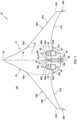
- FIG. 1 illustrates a blended wing body (BWB) aircraft 20.
- This aircraft 20 includes an airframe 22 and one or more propulsion systems 24A and 24B (generally referred to as "24").
- the aircraft airframe 22 includes a body 26 (e.g., a fuselage), one or more wings 28A and 28B (generally referred to as "28") and a vertical stabilizer 30.
- the aircraft 20 also includes an air system 32 for the vertical stabilizer 30.
- the aircraft body 26 extends longitudinally along a centerline 34 between and to a forward, upstream end 36 of the aircraft body 26 and an aft, downstream end 38 of the aircraft body 26.
- This centerline 34 may be a centerline axis of the aircraft 20, the aircraft airframe 22 and/or the aircraft body 26. Referring to FIG. 2 , the centerline 34 may be substantially (e.g., within +/- five degrees) or completely parallel with a horizon line when the aircraft 20 is flying in level flight.
- the aircraft body 26 extends vertically between and to opposing vertical bottom and top sides 40 and 42 of the aircraft body 26.
- the body bottom side 40 is vertically below the body top side 42 with respect to a gravitational direction when the aircraft 20 is flying in level flight.
- the aircraft body 26 extends laterally between and to opposing lateral sides 44A and 44B (generally referred to as "44") of the aircraft body 26.
- the aircraft wings 28 of FIGS. 1 and 3 are arranged to the opposing lateral sides 44 of the aircraft body 26.
- Each of the aircraft wings 28 is connected to (e.g., fixed to) the aircraft body 26.
- Each of the aircraft wings 28A, 28B projects spanwise along a span line of the respective aircraft wing 28A, 28B out from the aircraft body 26, at the respective body lateral side 44A, 44B, to a distal tip 46A, 46B of the respective aircraft wing 28.
- the respective aircraft wing 28 may (or may not) be configured with a winglet 48A, 48B.
- the wing leading edge 50 of FIG. 1 at a base of the respective aircraft wing 28, is longitudinally spaced aft, downstream from the body forward end 36.
- the wing trailing edge 52 of FIG. 1 at the wing base, is longitudinally spaced forward, upstream from the body aft end 38.
- the present disclosure is not limited to such an exemplary aircraft wing arrangement.
- the vertical stabilizer 30 of FIGS. 1 and 3 is disposed along the body top side 42. This vertical stabilizer 30 is arranged laterally between the aircraft propulsion systems 24 longitudinally at (e.g., on, adjacent or proximate) the body aft end 38.
- the vertical stabilizer 30 includes a vane 54 (e.g., a stationary surface) and one or more rudders 56A and 56B (generally referred to as "56”) (e.g., movable control surfaces).
- the vane 54 is connected to (e.g., fixed to) the aircraft body 26 at the body top side 42. This vane 54 projects spanwise along a span line of the vane 54 (e.g., vertically) away from the aircraft body 26 and its body top side 42. More particularly, the vane 54 of FIGS. 4A and 4B projects spanwise out from an exterior surface 60 (e.g., an outermost aero surface) of the aircraft body 26 at the body top side 42 to a distal tip 62 of the vane 54.
- an exterior surface 60 e.g., an outermost aero surface
- the vane 54 extends longitudinally along a mean line 64 (e.g., a chord line where the vane 54 is symmetrical, a camber line where the vane 54 is cambered) of the vane 54 from a leading edge 66 of the vane 54 to a trailing edge 68 of the vane 54.
- a mean line 64 e.g., a chord line where the vane 54 is symmetrical, a camber line where the vane 54 is cambered
- the vane 54 extends laterally (e.g., perpendicular to the mean line 64) between and to opposing lateral sides 70A and 70B (generally referred to as "70") of the vane 54.
- These vane lateral sides 70 extend longitudinally along the mean line 64 between and meet at the vane leading edge 66 and the vane trailing edge 68.
- each of the vane elements 66, 68, 70A and 70B extends spanwise from a base 72 of the vane 54 at the body top side 42 to
- FIG. 5A illustrates a base portion 74 of the vane 54.
- this base portion 74 may form a (e.g., complete) spanwise extending section of the vane 54 spanwise adjacent the aircraft body 26.
- the vane mean line 64 of the base portion 74 may be arranged parallel with the centerline 34.
- the vane mean line 64 may also be laterally aligned with the centerline 34.
- FIG. 5B illustrates an inner portion 76 of the vane 54.
- this inner portion 76 may form a (e.g., complete) spanwise extending section of the vane spanwise between the base portion 74 and an outer portion 77 of the vane 54.
- the vane mean line 64 of the inner portion 76 may be angularly offset from the vane mean line 64 of the base portion 74 (see FIG. 5A ) and/or the centerline 34.
- This inner portion stagger angle 78 may be a non-zero acute angle greater equal to or less than twenty degrees (20°); e.g., between one-half of a degrees (.5°) and five degrees (5°), between five degrees (5°) and ten degrees (10°), or between ten degrees (10°) and twenty degrees (20°). However, in other embodiments, the inner portion stagger angle 78 may be greater than twenty degrees (20°).
- the vane mean line 64 of the inner portion 76 may be laterally spaced from the vane mean line 64 of the base portion 74 (see FIG. 5A ) and/or the centerline 34 in a first lateral direction.
- the vane mean line 64 of the inner portion 76 may be laterally spaced from the vane mean line 64 of the base portion 74 (see FIG. 5A ) and/or the centerline 34 in a second lateral direction.
- the vane first side 70A along the inner portion 76 may form a pressure side of the inner portion 76
- the vane second side 70B along the inner portion 76 may form a suction side of the inner portion 76.
- FIG. 5C illustrates the outer portion 77 of the vane 54.
- this outer portion 77 may form a (e.g., complete) spanwise extending section of the vane 54 spanwise adjacent or near the vane tip 62.
- the vane mean line 64 of the outer portion 77 may be angularly offset from the vane mean line 64 of the base portion 74 (see FIG. 5A ) and/or the centerline 34.
- 5C is angularly offset from the vane mean line 64 of the base portion 74 (see FIG. 5A ) and/or the centerline 34 by an outer portion stagger angle 80.
- This outer portion stagger angle 80 may be a non-zero acute angle greater equal to or less than twenty degrees (20°); e.g., between one-half of a degrees (.5°) and five degrees (5°), between five degrees (5°) and ten degrees (10°), or between ten degrees (10°) and twenty degrees (20°).
- the inner portion stagger angle 78 may be greater than twenty degrees (20°).
- the outer portion stagger angle 80 may be equal in magnitude to the inner portion stagger angle 78, but opposite in direction to the inner portion stagger angle 78.
- the vane mean line 64 of the outer portion 77 may be laterally spaced from the vane mean line 64 of the base portion 74 (see FIG. 5A ) and/or the centerline 34 in the second lateral direction.
- the vane mean line 64 of the outer portion 77 may be laterally spaced from the vane mean line 64 of the base portion 74 (see FIG. 5A ) and/or the centerline 34 in the first lateral direction.
- the vane first side 70A along the outer portion 77 may form a suction side of the outer portion 77
- the vane second side 70B along the outer portion 77 may form a pressure side of the outer portion 77.
- the inner rudder 56A is movably attached to the vane 54 at the vane trailing edge 68.
- the inner rudder 56A may be pivotally attached to the inner portion 76 of the vane 54.
- the inner rudder 56A may be partially or completely spanwise aligned with the inner portion 76 of the vane 54.
- the inner rudder 56A of FIGS. 4A and 4B for example, extends spanwise along and overlaps the inner portion 76 of the vane 54 at the vane trailing edge 68.
- the outer rudder 56B is movably attached to the vane 54 at the vane trailing edge 68.
- the outer rudder 56B may be pivotally attached to the outer portion 77 of the vane 54.
- the outer rudder 56B may be partially or completely spanwise aligned with the outer portion 77 of the vane 54.
- the outer rudder 56B of FIGS. 4A and 4B extends spanwise along and overlaps the outer portion 77 of the vane 54 at the vane trailing edge 68.
- each of the aircraft propulsion systems 24 is connected to (e.g., fixed to) the aircraft body 26 at the body top side 42 and the body aft end 38.
- These aircraft propulsion systems 24 are arranged to the opposing lateral sides 70 of the vertical stabilizer 30 and its vane 54.
- the first propulsion system 24A of FIG. 1 for example, is spaced laterally from the vane 54 and its vane base 72 (see FIGS. 4A and 4B ) at the vane first side 70A by a lateral first distance.
- the second propulsion system 24B of FIG. 1 is spaced laterally from the vane 54 and its vane base 72 (see FIGS.
- the vane 54 may thereby be arranged laterally midway between the first propulsion system 24A and the second propulsion system 24B.
- the vane 54 of FIG. 1 may also longitudinally overlap a portion or an entirety of each aircraft propulsion system 24 along the centerline 34.
- the vane 54 thereby provides a divider (e.g., a structural barrier and/or a flow separator) laterally between the first propulsion system 24A and the second propulsion system 24B.
- This divider may reduce effects of crosswinds on the aircraft propulsion systems 24 and/or may prevent other disruptions associated with the aircraft propulsion systems 24 being in close proximity, such as reducing a likelihood of bird ingestion into both aircraft propulsion systems 24 as well as facilitating noise reduction (e.g., provide additional surfaces for acoustic attenuation).
- the vane leading edge 66 of FIG. 1 is disposed longitudinally forward, upstream of each aircraft propulsion system 24 along the centerline 34.
- Each aircraft propulsion system 24 of FIG. 1 is configured as a ducted rotor propulsion system.
- the ducted rotor propulsion system include, but are not limited to, a turbofan propulsion system and a turbojet propulsion system.
- Each aircraft propulsion system 24 of FIG. 1 for example, includes a ducted bladed rotor 82 (e.g., a fan rotor, a first stage compressor rotor, etc.) rotationally driven by an aircraft powerplant 84.
- This aircraft powerplant 84 may be configured as or otherwise include a turbine engine powered by traditional fuels or alternative fuels (e.g., sustainable aviation fuel, liquid hydrogen, etc.).
- the aircraft powerplant 84 may be configured as or otherwise include a rotary engine (e.g., a Wankel cycle engine), a hybrid-electric engine, or any other internal combustion (IC) engine or electric motor operable to drive rotation of the bladed rotor 82.
- a rotary engine e.g., a Wankel cycle engine
- IC internal combustion
- each aircraft propulsion system 24 may alternatively be configured as an open rotor propulsion system. Examples of the open rotor propulsion include, but are not limited to, a pusher fan propulsion system and a propfan propulsion system.
- the air system 32 of FIG. 1 includes one or more air circuits 86A and 86B (generally referred to as "86").
- the air circuits 86 are described below as fluidly discrete air circuits.
- the air circuits 86 of FIG. 1 are not fluidly coupled together along their lengths. It is contemplated, however, the air circuits 86 may alternatively be fluidly coupled at one or more locations along their lengths in other embodiments.
- Each air circuit 86A, 86B of FIG. 1 includes a circuit inlet 88A, 88B (generally referred to as “88") and a circuit outlet 90A, 90B (generally referred to as "90").
- Each air circuit 86 extends within the airframe 22 from its respective circuit inlet 88 to its respective circuit outlet 90.
- An upstream section of each air circuit 86 of FIG. 1 extends within the aircraft body 26 from its respective circuit inlet 88 to a downstream section of the respective air circuit 86.
- the downstream section of each air circuit 86 of FIG. 1 extends within the vane 54 from the respective upstream section of the respective air circuit 86 to its respective circuit outlet 90.
- each circuit inlet 88 is arranged with the aircraft body 26.
- each circuit inlet 88 may be configured as a recess such as a dimple, a depression, a channel, a notch or the like in the aircraft body 26.
- the circuit inlet 88 of FIG. 6 projects partially vertically into the aircraft body 26 from the body exterior surface 60.
- the circuit inlet 88 of FIG. 6 extends longitudinally within the aircraft body 26 and its body exterior surface 60 between opposing longitudinal ends 92 and 94 of the circuit inlet 88.
- the circuit inlet 88 of FIG. 6 extends laterally within the aircraft body 26 and its body exterior surface 60 between opposing lateral sides 96 of the circuit inlet 88; see also FIG. 7 .
- Each circuit inlet 88 may alternatively be configured as a scoop which projects vertically out from the aircraft body 26 and its exterior surface 60.
- each circuit inlet 88 may be configured as a flush mount scoop such as a NACA type inlet.
- each circuit inlet 88 is laterally offset (e.g., located remote) from the vertical stabilizer 30 and its vane 54.
- the first circuit inlet 88A of FIG. 1 is disposed to the vane first side 70A and laterally spaced from the vane 54 and its vane first side 70A by a lateral first distance. This first distance may be selected such that the first circuit inlet 88A is disposed upstream of an airflow inlet 98A into the first propulsion system 24A and its powerplant 84.
- the second circuit inlet 88B of FIG. 1 is disposed to the vane second side 70B and laterally spaced from the vane 54 and its vane second side 70B by a lateral second distance. This second distance may be selected such that the second circuit inlet 88B is disposed upstream of an airflow inlet 98B into the second propulsion system 24B and its powerplant 84.
- the second circuit inlet 88B of FIG. 1 for example, laterally overlaps (e.g., is laterally aligned with) the second propulsion system 24B and its airflow inlet 98B; see also FIG. 7 .
- Each circuit outlet 90 of FIG. 1 is arranged with the vertical stabilizer 30 and its vane 54.
- Each circuit outlet 90 of FIG. 1 for example, is arranged in and along a respective one of the vane sides 70. More particularly, the circuit outlets 90 are arranged to the opposing lateral sides 70 of the vane 54.
- the first circuit outlet 90A is arranged along the vane second side 70B in the inner portion 76.
- the second circuit outlet 90B is arranged along the vane first side 70A in the outer portion 77.
- the first circuit outlet 90A (see FIG. 4B ) is located radially inboard of the second circuit outlet 90B (see FIG. 4A ).
- the circuit outlets 90 may be longitudinally aligned along the vane 54 and/or the centerline 34.
- each circuit inlet 88 receives boundary layer air flowing along a respective upstream portion of the body exterior surface 60. This boundary layer air is directed into the respective air circuit 86 through its circuit inlet 88. The air flows through each air circuit 86 to its respective circuit outlet 90 where that air is exhausted from the air system 32 into an environment 100 external to the vertical stabilizer 30 and its vane 54 through the respective circuit outlet 90. Though described herein as being exhausted via circuit outlets 90 configured within a vane 54 of a vertical stabilizer 30, this is not intended to be so limiting, and the air may be configured to flow through the airframe 22 (e.g., the body 26) of the aircraft 20 and be exhausted out a circuit outlet 90 situated in the airframe 22.
- the airframe 22 e.g., the body 26
- the aircraft 20 may not include a vertical stabilizer 30 or the vertical stabilizer 30 may not include the air flow circuitry associated with removing boundary layer air.
- each aircraft propulsion system 24 may receive a substantially free stream of air (e.g., clean air, low turbulence air, etc.) at its airflow inlet 98A, 98B.
- a substantially free stream of air e.g., clean air, low turbulence air, etc.
- movement of air within the external environment 100 along the vane 54 may increase a pumping effect of the air through the air circuits 86.
- the air system 32 operates as a passive air system.
- the air system 32 for example, utilizes the flow of air along the aircraft 20 within the external environment 100 to power its operation.
- an active air system may utilize a pump or a compressor to boost or facilitate air flow.
- Exhausting the air from the circuit outlets 90 may also be utilized to facilitate aircraft maneuvering during flight.
- the inner rudder 56A may be moved towards the vane first side 70A / in the first lateral direction to facilitate yawing right / turning right; e.g., pivoted counterclockwise in FIG. 8A .
- the movement of the inner rudder 56A also increase a camber of the inner portion 76 of the vane 54. Increasing the camber may increase suction at the first circuit outlet 90A thereby pumping additional air through the first air circuit 86A to the suction side of the inner portion 76 of the vane 54.
- This additional air may push the air flowing within the external environment 100 along the suction side of the inner portion 76 of the vane 54 further away from the vane 54 thereby further increasing an effective camber of the inner portion 76 of the vane 54.
- This increase in the effective camber may generate additional lift to the second lateral direction such that the aircraft 20 yaws further to the right.
- the outer rudder 56B may (or may not) remain inline with the mean line 64 of the outer portion 77 of the vane 54.
- the inner rudder 56A and the outer rudder 56B may be independently actuated.
- the outer rudder 56B may be moved towards the vane second side 70B / in the second lateral direction to facilitate yawing left / turning left; e.g., pivoted clockwise in FIG. 9A .
- the movement of the outer rudder 56B also increase a camber of the outer portion 77 of the vane 54. Increasing the camber may increase suction at the second circuit outlet 90B thereby pumping additional air through the second air circuit 86B to the suction side of the outer portion 77 of the vane 54.
- This additional air may push the air flowing within the external environment 100 along the suction side of the outer portion 77 of the vane 54 further away from the vane 54 thereby further increasing an effective camber of the outer portion 77 of the vane 54.
- This increase in the effective camber may generate additional lift to the first lateral direction such that the aircraft 20 yaws further to the left.
- the inner rudder 56A may (or may not) remain inline with the mean line 64 of the inner portion 76 of the vane 54.
- the inner rudder 56A and the outer rudder 56B may be independently actuated.
- the vertical stabilizer 30 and its vane 54 may be utilized for lightning strike protection.
- the vertical stabilizer 30 and its vane 54 may also or alternatively be utilized to increase a radar signature of the aircraft 20 where that aircraft 20 is used for civilian aviation.
- the vertical stabilizer 30 is described above with a single vane 54.
- the vertical stabilizer 30 may alternatively include multiple vanes 54A and 54B (generally referred to as "54").
- Each vane 54A, 54B of FIG. 10 is connected to the aircraft body 26, and may project spanwise out from the aircraft body 26 to its respective vane tip 62A, 62B (generally referred to as "62").
- the first vane 54A may be configured with the second air circuit and its second circuit outlet.
- the second vane 54B may be configured with the first air circuit and its first circuit outlet.
- each vane 54A, 54B may be configured with a respective one of the rudders 56A, 56B; schematically shown.
- the rudder 56A of FIG. 10 for example, is movably attached to the first vane 54A.
- the rudder 56B of FIG. 10 is moveably attached to the second vane 54B.
- the aircraft 20 may be configured with a single vertical stabilizer 30. In other embodiments, referring to FIG. 11 , the aircraft 20 may be configured with multiple of the vertical stabilizers 30, where each vertical stabilizer 30 is arranged laterally between a respective laterally neighboring pair of the aircraft propulsion systems 24. As discussed above, in still yet other embodiments, the aircraft 20 may include no fixed vertical stabilizer 30 and the air circuits may be routed through the airframe 22 (e.g., the body 26) of the aircraft 20.
- the aircraft 20 is described above as the blended wing body aircraft for ease of description. However, it is contemplated the vertical stabilizer 30 and/or the air system 32 may also be utilized with various other types of aircraft.
Landscapes
- Engineering & Computer Science (AREA)
- Aviation & Aerospace Engineering (AREA)
- Chemical & Material Sciences (AREA)
- Combustion & Propulsion (AREA)
- Structures Of Non-Positive Displacement Pumps (AREA)
Abstract
A system is provided for an aircraft (20). This aircraft system includes an aircraft (20) and an air system (32). The airframe (22) includes a body (26) and a vane (54) connected to the body (26). The vane (54) projects spanwise away from the body (26) to a vane tip (62). The vane extends longitudinally between a leading edge (66) and a trailing edge (68). The vane (54) extends laterally between a first vane side (70A) and a second vane side (70B). The air system (32) includes a circuit inlet (88), a circuit outlet (90A) and an air circuit (86). The circuit inlet (88) is arranged with the body (26) and laterally offset from the vane (54). The circuit outlet (90A) is arranged with the vane (54). The air circuit (86) extends within the airframe (22) from the circuit inlet (88) to the circuit outlet (90A).
Description
- This disclosure relates generally to an aircraft and, more particularly, to an vertical stabilizer for the aircraft.
- An aircraft may include a vertical stabilizer at an aft, downstream end of the aircraft. Various types and configurations of aircraft and vertical stabilizers are known in the art. While these known aircraft and vertical stabilizers have various benefits, there is still room in the art for improvement.
- According to an aspect of the present invention, a system is provided for an aircraft. This aircraft system includes an aircraft and an air system. The airframe includes a body and a vane connected to the body. The vane projects spanwise away from the body to a vane tip. The vane extends longitudinally between a leading edge and a trailing edge. The vane extends laterally between a first vane side and a second vane side. The air system includes a circuit inlet, a circuit outlet and an air circuit. The circuit inlet is arranged with the body and laterally offset from the vane. The circuit outlet is arranged with the vane. The air circuit extends within the airframe from the circuit inlet to the circuit outlet.
- In an embodiment of the above, the body may be configured as a blended wing body.
- In an embodiment according to any of the previous embodiments, the system may also include a powerplant including a powerplant inlet. The powerplant may be disposed to the first vane side and connected to the body. The circuit inlet may be disposed upstream of and laterally overlapping the powerplant inlet.
- In an embodiment according to any of the previous embodiments, the powerplant may be configured as a propulsion system for the aircraft.
- In an embodiment according to any of the previous embodiments, the system may also include a second powerplant disposed to the second vane side and connected to the body.
- In an embodiment according to any of the previous embodiments, the second powerplant may include a second powerplant inlet. The air system may also include a second circuit inlet disposed upstream of and laterally overlapping the second powerplant inlet.
- In an embodiment according to any of the previous embodiments, the vane may project spanwise out from an exterior surface of the body to the vane tip. The circuit inlet may include a recess projecting into the body from the exterior surface of the body.
- In an embodiment according to any of the previous embodiments, the circuit outlet may be disposed along the vane second side.
- In an embodiment according to any of the previous embodiments, the circuit inlet may be disposed to the vane first side.
- In an embodiment according to any of the previous embodiments, at least a first portion of the vane may be angularly offset from a centerline of the airframe by a first portion stagger angle such that the vane second side along the first portion of the vane forms a suction side of the first portion of the vane. The circuit outlet may be disposed along the suction side of the first portion of the vane.
- In an embodiment according to any of the previous embodiments, a second portion of the vane may be angularly offset from the centerline of the airframe by a second portion stagger angle such that the vane first side along the second portion of the vane forms a suction side of the second portion of the vane. The air system may also include a second circuit outlet disposed along the suction side of the second portion of the vane.
- In an embodiment according to any of the previous embodiments, the system may also include a first rudder and a second rudder. The first rudder may be arranged along the first portion of the vane at the trailing edge. The second rudder may be arranged along the second portion of the vane at the trailing edge. The first rudder may be configured to move independent of the second rudder.
- In an embodiment according to any of the previous embodiments, the first portion of the vane may be located spanwise between the body and the second portion of the vane.
- In an embodiment according to any of the previous embodiments, the circuit inlet may be a first circuit inlet. The circuit outlet may be a first circuit outlet. The air circuit may be a first air circuit. The air system may also include a second circuit inlet, a second circuit outlet and a second air circuit extending within the airframe from the second circuit inlet to the second circuit outlet. The vane may be a first vane. The airframe may also include a second vane connected to the body. The second vane may project spanwise away from the body to a vane tip of the second vane. The second vane may extend longitudinally between a leading edge of the second vane and a trailing edge of the second vane. The second vane may extend laterally between a first vane side of the second vane and a second vane side of the second vane. The second vane side of the second vane may laterally face the first vane side of the first vane. The second circuit inlet may be arranged with the body and may be laterally offset from the second vane. The second circuit outlet may be arranged with the second vane.
- In an embodiment according to any of the previous embodiments, the first circuit outlet may be arranged along the second vane side of the first vane. The second circuit outlet may be arranged along the first vane side of the second vane.
- According to another aspect of the present invention, another system is provided for an aircraft. This aircraft system includes a vertical stabilizer and an air system. The vertical stabilizer is configured as or otherwise includes a vane. The vane projects spanwise out to a vane tip. The vane extends longitudinally between a leading edge and a trailing edge. The vane extends laterally between a first vane side and a second vane side. The air system includes a first air circuit and a second air circuit. The first air circuit extends from a first circuit inlet to a first circuit outlet. The first circuit inlet is located remote from the vane. The first circuit outlet is arranged along the second vane side. The second air circuit extends from a second circuit inlet to a second circuit outlet. The second circuit inlet is located remote from the vane. The second circuit outlet is arranged along the first vane side.
- In an embodiment of the above, the first circuit inlet may be disposed to and laterally spaced from the vane first side. The second circuit inlet may be disposed to and laterally spaced from the vane second side.
- In an embodiment according to any of the previous embodiments, the second air circuit may be fluidly decoupled from the first air circuit.
- In an embodiment according to any of the previous embodiments, the vertical stabilizer may also include a first rudder and a second rudder. The first rudder may be located at the trailing edge and spanwise overlap the first circuit outlet. The second rudder may be located at the trailing edge and spanwise overlap the second circuit outlet.
- In an embodiment according to any of the previous embodiments, the system may also include a first propulsion system and a second propulsion system. The first propulsion system may include a first airflow inlet. The first circuit inlet may be laterally aligned with and upstream of the first airflow inlet. The second propulsion system may include a second airflow inlet. The second circuit inlet may be laterally aligned with and upstream of the second airflow inlet.
- In an embodiment according to any of the previous embodiments, the vane may be located laterally between and longitudinally overlap the first propulsion system and the second propulsion system.
- According to still another aspect of the present invention, another system is provided for an aircraft. This aircraft system includes an airframe body, a vane, a first rudder and a second rudder. The airframe body has a centerline. The vane is connected to the aircraft body. The vane projects spanwise out to a vane tip. The vane extends longitudinally between a leading edge and a trailing edge. The vane extends laterally between a first vane side and a second vane side. A first portion of the vane has a first mean line extending from the leading edge to the trailing edge. The first mean line is angularly offset from the centerline by a first stagger angle. A second portion of the vane has a second mean line extending from the leading edge to the trailing edge. The second mean line is angularly offset from the centerline by a second stagger angle opposite the first stagger angle. The first rudder is attached to the vane and spanwise overlaps the first portion of the vane. The second rudder is attached to the vane and spanwise overlaps the second portion of the vane.
- In an embodiment of the above, the system may also include an air system including a first air circuit and a second air circuit. The first air circuit may extend from a first circuit inlet to a first circuit outlet. The first circuit inlet may be disposed along the airframe body remote from the vane. The first circuit outlet may be arranged along the first portion of the vane at the second vane side. The second air circuit may extend from a second circuit inlet to a second circuit outlet. The second circuit inlet may be disposed along the airframe body remote from the vane. The second circuit outlet may be arranged along the second portion of the vane at the first vane side.
- In an embodiment according to any of the previous embodiments, a first portion of the vane may have a first mean line extending from the leading edge to the trailing edge. The first circuit outlet may be arranged along the first portion of the vane. A second portion of the vane may have a second mean line extending from the leading edge to the trailing edge. The second circuit outlet may be arranged along the second portion of the vane. The first mean line may be angularly offset from the second mean line.
- In an embodiment according to any of the previous embodiments, the airframe may also include a vertical stabilizer located at an aft end of the body. The vertical stabilizer may include the vane.
- The present disclosure may include any one or more of the individual features disclosed above and/or below alone or in any combination thereof.
- The foregoing features and the operation of the invention will become more apparent in light of the following description and the accompanying drawings.
-
-
FIG. 1 is a plan view illustration of an aircraft. -
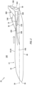
FIG. 2 is a side view illustration of the aircraft. -
FIG. 3 is an end view illustration of the aircraft. -
FIG. 4A is a partial side view illustration of a section of the aircraft along a first side of a vertical stabilizer. -
FIG. 4B is a partial side view illustration of a section of the aircraft along a second side of the vertical stabilizer. -
FIGS. 5A-C are partial schematic sectional illustrations of the vertical stabilizer at various span locations. -
FIG. 6 is a partial sectional illustration of a portion of the aircraft at an interface between an air circuit and a propulsion system. -
FIG. 7 is a plan view illustration of a portion of the aircraft at the interface between the air circuit and the propulsion system. -
FIGS. 8A and 8B are partial schematic sectional illustrations of the vertical stabilizer at various span locations during a first aircraft maneuver. -
FIGS. 9A and 9B are partial schematic sectional illustrations of the vertical stabilizer at various span locations during a second aircraft maneuver. -
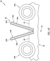
FIG. 10 is a partial end view illustration of the aircraft with another vertical stabilizer arrangement. -
FIG. 11 is a partial end view illustration of the aircraft with multiple vertical stabilizers. -
FIG. 1 illustrates a blended wing body (BWB)aircraft 20. Thisaircraft 20 includes anairframe 22 and one ormore propulsion systems aircraft airframe 22 includes a body 26 (e.g., a fuselage), one ormore wings vertical stabilizer 30. Theaircraft 20 also includes anair system 32 for thevertical stabilizer 30. - The
aircraft body 26 extends longitudinally along acenterline 34 between and to a forward,upstream end 36 of theaircraft body 26 and an aft,downstream end 38 of theaircraft body 26. Thiscenterline 34 may be a centerline axis of theaircraft 20, theaircraft airframe 22 and/or theaircraft body 26. Referring toFIG. 2 , thecenterline 34 may be substantially (e.g., within +/- five degrees) or completely parallel with a horizon line when theaircraft 20 is flying in level flight. Theaircraft body 26 extends vertically between and to opposing vertical bottom andtop sides aircraft body 26. Thebody bottom side 40 is vertically below thebody top side 42 with respect to a gravitational direction when theaircraft 20 is flying in level flight. Referring toFIGS. 1 and3 , theaircraft body 26 extends laterally between and to opposinglateral sides aircraft body 26. - The aircraft wings 28 of
FIGS. 1 and3 are arranged to the opposing lateral sides 44 of theaircraft body 26. Each of the aircraft wings 28 is connected to (e.g., fixed to) theaircraft body 26. Each of theaircraft wings respective aircraft wing aircraft body 26, at the respective bodylateral side distal tip wing tip winglet FIG. 1 extends longitudinally along a mean line of the respective aircraft wing 28 from aleading edge edge FIG. 1 , at a base of the respective aircraft wing 28, is longitudinally spaced aft, downstream from the body forward end 36. The wing trailing edge 52 ofFIG. 1 , at the wing base, is longitudinally spaced forward, upstream from the body aftend 38. The present disclosure, however, is not limited to such an exemplary aircraft wing arrangement. - The
vertical stabilizer 30 ofFIGS. 1 and3 is disposed along thebody top side 42. Thisvertical stabilizer 30 is arranged laterally between theaircraft propulsion systems 24 longitudinally at (e.g., on, adjacent or proximate) the body aftend 38. Referring toFIGS. 4A and 4B , thevertical stabilizer 30 includes a vane 54 (e.g., a stationary surface) and one ormore rudders - The
vane 54 is connected to (e.g., fixed to) theaircraft body 26 at thebody top side 42. Thisvane 54 projects spanwise along a span line of the vane 54 (e.g., vertically) away from theaircraft body 26 and itsbody top side 42. More particularly, thevane 54 ofFIGS. 4A and 4B projects spanwise out from an exterior surface 60 (e.g., an outermost aero surface) of theaircraft body 26 at thebody top side 42 to adistal tip 62 of thevane 54. Thevane 54 extends longitudinally along a mean line 64 (e.g., a chord line where thevane 54 is symmetrical, a camber line where thevane 54 is cambered) of thevane 54 from a leadingedge 66 of thevane 54 to a trailingedge 68 of thevane 54. Referring toFIGS. 5A-C , thevane 54 extends laterally (e.g., perpendicular to the mean line 64) between and to opposinglateral sides vane 54. These vane lateral sides 70 extend longitudinally along themean line 64 between and meet at thevane leading edge 66 and thevane trailing edge 68. Referring toFIGS. 4A and 4B , each of thevane elements base 72 of thevane 54 at thebody top side 42 to thevane tip 62. -
FIG. 5A illustrates abase portion 74 of thevane 54. Referring toFIGS. 4A and 4B , thisbase portion 74 may form a (e.g., complete) spanwise extending section of thevane 54 spanwise adjacent theaircraft body 26. At one or more locations spanwise along the base portion 74 (e.g., at the vane base 72), referring toFIG. 5A , the vane meanline 64 of thebase portion 74 may be arranged parallel with thecenterline 34. The vane meanline 64 may also be laterally aligned with thecenterline 34. -
FIG. 5B illustrates aninner portion 76 of thevane 54. Referring toFIGS. 4A and 4B , thisinner portion 76 may form a (e.g., complete) spanwise extending section of the vane spanwise between thebase portion 74 and anouter portion 77 of thevane 54. At one or more locations spanwise along the inner portion 76 (e.g., at a spanwise midpoint of the inner portion 76), referring toFIG. 5B , the vane meanline 64 of theinner portion 76 may be angularly offset from the vane meanline 64 of the base portion 74 (seeFIG. 5A ) and/or thecenterline 34. The vane meanline 64 of theinner portion 76 ofFIG. 5B , for example, is angularly offset from the vane meanline 64 of the base portion 74 (seeFIG. 5A ) and/or thecenterline 34 by an inner portion staggerangle 78. This inner portion staggerangle 78 may be a non-zero acute angle greater equal to or less than twenty degrees (20°); e.g., between one-half of a degrees (.5°) and five degrees (5°), between five degrees (5°) and ten degrees (10°), or between ten degrees (10°) and twenty degrees (20°). However, in other embodiments, the inner portion staggerangle 78 may be greater than twenty degrees (20°). - At the
vane trailing edge 68, the vane meanline 64 of theinner portion 76 may be laterally spaced from the vane meanline 64 of the base portion 74 (seeFIG. 5A ) and/or thecenterline 34 in a first lateral direction. In addition or alternatively, at thevane leading edge 66, the vane meanline 64 of theinner portion 76 may be laterally spaced from the vane meanline 64 of the base portion 74 (seeFIG. 5A ) and/or thecenterline 34 in a second lateral direction. With this staggered arrangement, the vanefirst side 70A along theinner portion 76 may form a pressure side of theinner portion 76, and the vanesecond side 70B along theinner portion 76 may form a suction side of theinner portion 76. -
FIG. 5C illustrates theouter portion 77 of thevane 54. Referring toFIGS. 4A and 4B , thisouter portion 77 may form a (e.g., complete) spanwise extending section of thevane 54 spanwise adjacent or near thevane tip 62. At one or more locations spanwise along the outer portion 77 (e.g., at or near the vane tip 62), referring toFIG. 5C , the vane meanline 64 of theouter portion 77 may be angularly offset from the vane meanline 64 of the base portion 74 (seeFIG. 5A ) and/or thecenterline 34. The vane meanline 64 of theouter portion 77 ofFIG. 5C , for example, is angularly offset from the vane meanline 64 of the base portion 74 (seeFIG. 5A ) and/or thecenterline 34 by an outer portion staggerangle 80. This outer portion staggerangle 80 may be a non-zero acute angle greater equal to or less than twenty degrees (20°); e.g., between one-half of a degrees (.5°) and five degrees (5°), between five degrees (5°) and ten degrees (10°), or between ten degrees (10°) and twenty degrees (20°). However, in other embodiments, the inner portion staggerangle 78 may be greater than twenty degrees (20°). The outer portion staggerangle 80 may be equal in magnitude to the inner portion staggerangle 78, but opposite in direction to the inner portion staggerangle 78. - At the
vane trailing edge 68, the vane meanline 64 of theouter portion 77 may be laterally spaced from the vane meanline 64 of the base portion 74 (seeFIG. 5A ) and/or thecenterline 34 in the second lateral direction. In addition or alternatively, at thevane leading edge 66, the vane meanline 64 of theouter portion 77 may be laterally spaced from the vane meanline 64 of the base portion 74 (seeFIG. 5A ) and/or thecenterline 34 in the first lateral direction. With this staggered arrangement, the vanefirst side 70A along theouter portion 77 may form a suction side of theouter portion 77, and the vanesecond side 70B along theouter portion 77 may form a pressure side of theouter portion 77. - Referring to
FIGS. 4A, 4B and5B , theinner rudder 56A is movably attached to thevane 54 at thevane trailing edge 68. Theinner rudder 56A, for example, may be pivotally attached to theinner portion 76 of thevane 54. Referring toFIGS. 4A and 4B , theinner rudder 56A may be partially or completely spanwise aligned with theinner portion 76 of thevane 54. Theinner rudder 56A ofFIGS. 4A and 4B , for example, extends spanwise along and overlaps theinner portion 76 of thevane 54 at thevane trailing edge 68. - Referring to
FIGS. 4A, 4B and5C , theouter rudder 56B is movably attached to thevane 54 at thevane trailing edge 68. Theouter rudder 56B, for example, may be pivotally attached to theouter portion 77 of thevane 54. Referring toFIGS. 4A and 4B , theouter rudder 56B may be partially or completely spanwise aligned with theouter portion 77 of thevane 54. Theouter rudder 56B ofFIGS. 4A and 4B , for example, extends spanwise along and overlaps theouter portion 77 of thevane 54 at thevane trailing edge 68. - Referring to
FIG. 1 , each of theaircraft propulsion systems 24 is connected to (e.g., fixed to) theaircraft body 26 at thebody top side 42 and the body aftend 38. Theseaircraft propulsion systems 24 are arranged to the opposing lateral sides 70 of thevertical stabilizer 30 and itsvane 54. Thefirst propulsion system 24A ofFIG. 1 , for example, is spaced laterally from thevane 54 and its vane base 72 (seeFIGS. 4A and 4B ) at the vanefirst side 70A by a lateral first distance. Thesecond propulsion system 24B ofFIG. 1 is spaced laterally from thevane 54 and its vane base 72 (seeFIGS. 4A and 4B ) at the vanesecond side 70B by a lateral second distance, which may be equal to the first distance. Thevane 54 may thereby be arranged laterally midway between thefirst propulsion system 24A and thesecond propulsion system 24B. Thevane 54 ofFIG. 1 may also longitudinally overlap a portion or an entirety of eachaircraft propulsion system 24 along thecenterline 34. Thevane 54 thereby provides a divider (e.g., a structural barrier and/or a flow separator) laterally between thefirst propulsion system 24A and thesecond propulsion system 24B. This divider may reduce effects of crosswinds on theaircraft propulsion systems 24 and/or may prevent other disruptions associated with theaircraft propulsion systems 24 being in close proximity, such as reducing a likelihood of bird ingestion into bothaircraft propulsion systems 24 as well as facilitating noise reduction (e.g., provide additional surfaces for acoustic attenuation). Here, thevane leading edge 66 ofFIG. 1 is disposed longitudinally forward, upstream of eachaircraft propulsion system 24 along thecenterline 34. - Each
aircraft propulsion system 24 ofFIG. 1 is configured as a ducted rotor propulsion system. Examples of the ducted rotor propulsion system include, but are not limited to, a turbofan propulsion system and a turbojet propulsion system. Eachaircraft propulsion system 24 ofFIG. 1 , for example, includes a ducted bladed rotor 82 (e.g., a fan rotor, a first stage compressor rotor, etc.) rotationally driven by anaircraft powerplant 84. Thisaircraft powerplant 84 may be configured as or otherwise include a turbine engine powered by traditional fuels or alternative fuels (e.g., sustainable aviation fuel, liquid hydrogen, etc.). Alternatively, theaircraft powerplant 84 may be configured as or otherwise include a rotary engine (e.g., a Wankel cycle engine), a hybrid-electric engine, or any other internal combustion (IC) engine or electric motor operable to drive rotation of thebladed rotor 82. The present disclosure, however, is not limited to the foregoing exemplary aircraft propulsion system and/or powerplant types or configurations. It is contemplated, for example, eachaircraft propulsion system 24 may alternatively be configured as an open rotor propulsion system. Examples of the open rotor propulsion include, but are not limited to, a pusher fan propulsion system and a propfan propulsion system. - The
air system 32 ofFIG. 1 includes one ormore air circuits FIG. 1 , for example, are not fluidly coupled together along their lengths. It is contemplated, however, the air circuits 86 may alternatively be fluidly coupled at one or more locations along their lengths in other embodiments. - Each
air circuit FIG. 1 includes acircuit inlet circuit outlet airframe 22 from its respective circuit inlet 88 to its respective circuit outlet 90. An upstream section of each air circuit 86 ofFIG. 1 , for example, extends within theaircraft body 26 from its respective circuit inlet 88 to a downstream section of the respective air circuit 86. The downstream section of each air circuit 86 ofFIG. 1 extends within thevane 54 from the respective upstream section of the respective air circuit 86 to its respective circuit outlet 90. - Each circuit inlet 88 is arranged with the
aircraft body 26. Referring toFIG. 6 , each circuit inlet 88 may be configured as a recess such as a dimple, a depression, a channel, a notch or the like in theaircraft body 26. The circuit inlet 88 ofFIG. 6 , for example, projects partially vertically into theaircraft body 26 from thebody exterior surface 60. The circuit inlet 88 ofFIG. 6 extends longitudinally within theaircraft body 26 and itsbody exterior surface 60 between opposing longitudinal ends 92 and 94 of the circuit inlet 88. The circuit inlet 88 ofFIG. 6 extends laterally within theaircraft body 26 and itsbody exterior surface 60 between opposinglateral sides 96 of the circuit inlet 88; see alsoFIG. 7 . The present disclosure, however, is not limited to such an exemplary circuit inlet configuration. Each circuit inlet 88, for example, may alternatively be configured as a scoop which projects vertically out from theaircraft body 26 and itsexterior surface 60. In another example, each circuit inlet 88 may be configured as a flush mount scoop such as a NACA type inlet. - Referring to
FIG. 1 , each circuit inlet 88 is laterally offset (e.g., located remote) from thevertical stabilizer 30 and itsvane 54. Thefirst circuit inlet 88A ofFIG. 1 , for example, is disposed to the vanefirst side 70A and laterally spaced from thevane 54 and its vanefirst side 70A by a lateral first distance. This first distance may be selected such that thefirst circuit inlet 88A is disposed upstream of anairflow inlet 98A into thefirst propulsion system 24A and itspowerplant 84. Thefirst circuit inlet 88A ofFIG. 1 , for example, laterally overlaps (e.g., is laterally aligned with) thefirst propulsion system 24A and itsairflow inlet 98A; see alsoFIG. 7 . Similarly, thesecond circuit inlet 88B ofFIG. 1 is disposed to the vanesecond side 70B and laterally spaced from thevane 54 and its vanesecond side 70B by a lateral second distance. This second distance may be selected such that thesecond circuit inlet 88B is disposed upstream of anairflow inlet 98B into thesecond propulsion system 24B and itspowerplant 84. Thesecond circuit inlet 88B ofFIG. 1 , for example, laterally overlaps (e.g., is laterally aligned with) thesecond propulsion system 24B and itsairflow inlet 98B; see alsoFIG. 7 . - Each circuit outlet 90 of
FIG. 1 is arranged with thevertical stabilizer 30 and itsvane 54. Each circuit outlet 90 ofFIG. 1 , for example, is arranged in and along a respective one of the vane sides 70. More particularly, the circuit outlets 90 are arranged to the opposing lateral sides 70 of thevane 54. For example, referring toFIGS. 4B and5B , thefirst circuit outlet 90A is arranged along the vanesecond side 70B in theinner portion 76. Referring toFIGS. 4A and5C , thesecond circuit outlet 90B is arranged along the vanefirst side 70A in theouter portion 77. With this arrangement, thefirst circuit outlet 90A (seeFIG. 4B ) is located radially inboard of thesecond circuit outlet 90B (seeFIG. 4A ). However, referring toFIG. 1 , the circuit outlets 90 may be longitudinally aligned along thevane 54 and/or thecenterline 34. - During operation of the
air system 32, each circuit inlet 88 receives boundary layer air flowing along a respective upstream portion of thebody exterior surface 60. This boundary layer air is directed into the respective air circuit 86 through its circuit inlet 88. The air flows through each air circuit 86 to its respective circuit outlet 90 where that air is exhausted from theair system 32 into anenvironment 100 external to thevertical stabilizer 30 and itsvane 54 through the respective circuit outlet 90. Though described herein as being exhausted via circuit outlets 90 configured within avane 54 of avertical stabilizer 30, this is not intended to be so limiting, and the air may be configured to flow through the airframe 22 (e.g., the body 26) of theaircraft 20 and be exhausted out a circuit outlet 90 situated in theairframe 22. In such an embodiment, theaircraft 20 may not include avertical stabilizer 30 or thevertical stabilizer 30 may not include the air flow circuitry associated with removing boundary layer air. By removing the boundary layer air upstream of theaircraft propulsion systems 24, eachaircraft propulsion system 24 may receive a substantially free stream of air (e.g., clean air, low turbulence air, etc.) at itsairflow inlet FIGS. 5B and 5C ), movement of air within theexternal environment 100 along thevane 54 may increase a pumping effect of the air through the air circuits 86. With this arrangement, theair system 32 operates as a passive air system. Theair system 32, for example, utilizes the flow of air along theaircraft 20 within theexternal environment 100 to power its operation. By contrast, an active air system may utilize a pump or a compressor to boost or facilitate air flow. - Exhausting the air from the circuit outlets 90 may also be utilized to facilitate aircraft maneuvering during flight. For example, referring to
FIG. 8A , theinner rudder 56A may be moved towards the vanefirst side 70A / in the first lateral direction to facilitate yawing right / turning right; e.g., pivoted counterclockwise inFIG. 8A . In addition to redirecting the air in theexterior environment 100 flowing along theinner portion 76 of thevane 54, the movement of theinner rudder 56A also increase a camber of theinner portion 76 of thevane 54. Increasing the camber may increase suction at thefirst circuit outlet 90A thereby pumping additional air through thefirst air circuit 86A to the suction side of theinner portion 76 of thevane 54. This additional air may push the air flowing within theexternal environment 100 along the suction side of theinner portion 76 of thevane 54 further away from thevane 54 thereby further increasing an effective camber of theinner portion 76 of thevane 54. This increase in the effective camber may generate additional lift to the second lateral direction such that theaircraft 20 yaws further to the right. During this maneuver, referring toFIG. 8B , theouter rudder 56B may (or may not) remain inline with themean line 64 of theouter portion 77 of thevane 54. Thus, theinner rudder 56A and theouter rudder 56B may be independently actuated. - In another example, referring to
FIG. 9A , theouter rudder 56B may be moved towards the vanesecond side 70B / in the second lateral direction to facilitate yawing left / turning left; e.g., pivoted clockwise inFIG. 9A . In addition to redirecting the air in theexternal environment 100 flowing along theouter portion 77 of thevane 54, the movement of theouter rudder 56B also increase a camber of theouter portion 77 of thevane 54. Increasing the camber may increase suction at thesecond circuit outlet 90B thereby pumping additional air through thesecond air circuit 86B to the suction side of theouter portion 77 of thevane 54. This additional air may push the air flowing within theexternal environment 100 along the suction side of theouter portion 77 of thevane 54 further away from thevane 54 thereby further increasing an effective camber of theouter portion 77 of thevane 54. This increase in the effective camber may generate additional lift to the first lateral direction such that theaircraft 20 yaws further to the left. During this maneuver, referring toFIG. 9B , theinner rudder 56A may (or may not) remain inline with themean line 64 of theinner portion 76 of thevane 54. Thus, theinner rudder 56A and theouter rudder 56B may be independently actuated. - In some embodiments, the
vertical stabilizer 30 and itsvane 54 may be utilized for lightning strike protection. Thevertical stabilizer 30 and itsvane 54 may also or alternatively be utilized to increase a radar signature of theaircraft 20 where thataircraft 20 is used for civilian aviation. - The
vertical stabilizer 30 is described above with asingle vane 54. The present disclosure, however, is not limited to such an exemplary arrangement. For example, referring toFIG. 10 , thevertical stabilizer 30 may alternatively includemultiple vanes vane FIG. 10 is connected to theaircraft body 26, and may project spanwise out from theaircraft body 26 to itsrespective vane tip first vane 54A may be configured with the second air circuit and its second circuit outlet. Thesecond vane 54B may be configured with the first air circuit and its first circuit outlet. Here, eachvane rudders rudder 56A ofFIG. 10 , for example, is movably attached to thefirst vane 54A. Therudder 56B ofFIG. 10 is moveably attached to thesecond vane 54B. - In some embodiments, referring to
FIGS. 3 and10 , theaircraft 20 may be configured with a singlevertical stabilizer 30. In other embodiments, referring toFIG. 11 , theaircraft 20 may be configured with multiple of thevertical stabilizers 30, where eachvertical stabilizer 30 is arranged laterally between a respective laterally neighboring pair of theaircraft propulsion systems 24. As discussed above, in still yet other embodiments, theaircraft 20 may include no fixedvertical stabilizer 30 and the air circuits may be routed through the airframe 22 (e.g., the body 26) of theaircraft 20. - The
aircraft 20 is described above as the blended wing body aircraft for ease of description. However, it is contemplated thevertical stabilizer 30 and/or theair system 32 may also be utilized with various other types of aircraft. - While various embodiments of the present disclosure have been described, it will be apparent to those of ordinary skill in the art that many more embodiments and implementations are possible within the scope of the disclosure. For example, the present disclosure as described herein includes several aspects and embodiments that include particular features. Although these features may be described individually, it is within the scope of the present disclosure that some or all of these features may be combined with any one of the aspects and remain within the scope of the disclosure. Accordingly, the present disclosure is not to be restricted except in light of the attached claims and their equivalents.
Claims (15)
- A system for an aircraft, comprising:an airframe (22) including a body (26) and a vane (54) connected to the body (26), the vane (54) projecting spanwise away from the body (26) to a vane tip (62), the vane (54) extending longitudinally between a leading edge (66) and a trailing edge (68), and the vane (54) extending laterally between a first vane side (70A) and a second vane side (70B); andan air system (32) including a circuit inlet (88), a circuit outlet (90A) and an air circuit (86), the circuit inlet (88) arranged with the body (26) and laterally offset from the vane (54), the circuit outlet (90A) arranged with the vane (54), and the air circuit (86) extending within the airframe (22) from the circuit inlet (88) to the circuit outlet (90A).
- The system of claim 1, wherein the body (26) is configured as a blended wing body (26).
- The system of claim 1 or 2, further comprising:a powerplant (84) comprising a powerplant inlet (98A), the powerplant (84) disposed to the first vane side (70A) and connected to the body (26); andthe circuit inlet (88) disposed upstream of and laterally overlapping the powerplant inlet (98A), optionally wherein the powerplant (84) is configured as a propulsion system (24) for the aircraft (20).
- The system of claim 3, further comprising a second powerplant (84) disposed to the second vane side (70B) and connected to the body (26).
- The system of claim 4, wherein:the second powerplant (84) comprises a second powerplant inlet (98B); andthe air system (32) further includes a second circuit inlet (88B) disposed upstream of and laterally overlapping the second powerplant inlet (98B).
- The system of any preceding claim, wherein:the vane (54) projects spanwise out from an exterior surface (60) of the body (26) to the vane tip (62); andthe circuit inlet (88) comprises a recess projecting into the body (26) from the exterior surface (60) of the body (26).
- The system of any preceding claim, wherein the circuit outlet (90A) is disposed along the second vane side (70B), and/or the circuit inlet (88) is disposed to the first vane side (70A).
- The system of any preceding claim, wherein:at least a first portion (76) of the vane (54) is angularly offset from a centerline (34) of the airframe (22) by a first portion stagger angle (78) such that the second vane side (70B) along the first portion (76) of the vane (54) forms a suction side of the first portion (76) of the vane (54); andthe circuit outlet (90A) is disposed along the suction side of the first portion (76) of the vane (54).
- The system of claim 8, wherein:a second portion (77) of the vane (54) is angularly offset from the centerline (34) of the airframe (22) by a second portion stagger angle (80) such that the first vane side (70A) along the second portion (77) of the vane (54) forms a suction side of the second portion (77) of the vane (54); andthe air system (32) further includes a second circuit outlet (90B) disposed along the suction side of the second portion (77) of the vane (54).
- The system of claim 9, wherein:the system further comprises a first rudder (56A) arranged along the first portion (76) of the vane (54) at the trailing edge (68) and a second rudder (56B) arranged along the second portion (77) of the vane (54) at the trailing edge (68), the first rudder (56A) configured to move independent of the second rudder (56B); and/orthe first portion (76) of the vane (54) is located spanwise between the body (26) and the second portion (77) of the vane (54).
- The system of any preceding claim, wherein:the circuit inlet (88) is a first circuit inlet (88A), the circuit outlet (90A) is a first circuit outlet (90A), the air circuit (86) is a first air circuit (86A), and the air system (32) further includes a second circuit inlet (88B), a second circuit outlet (90B) and a second air circuit (86B) extending within the airframe (22) from the second circuit inlet (88B) to the second circuit outlet (90B);the vane (54) is a first vane (54A), and the airframe (22) further includes a second vane (54B) connected to the body (26);the second vane (54B) projects spanwise away from the body (26) to a vane tip (62B) of the second vane (54B), the second vane (54B) extends longitudinally between a leading edge of the second vane (54B) and a trailing edge of the second vane (54B), the second vane (54B) extends laterally between a first vane side of the second vane (54B) and a second vane side of the second vane (54B), and the second vane side (70B) of the second vane (54B) laterally faces the first vane side (70A) of the first vane (54A); andthe second circuit inlet (88B) is arranged with the body (26) and is laterally offset from the second vane (54B), and the second circuit outlet (90B) is arranged with the second vane (54B), optionally wherein:the first circuit outlet (90A) is arranged along the second vane side (70B) of the first vane (54A); andthe second circuit outlet (90B) is arranged along the first vane side (70A) of the second vane (54B).
- A system for an aircraft, comprising:a vertical stabilizer (30) comprising a vane (54), the vane (54) projecting spanwise out to a vane tip (62), the vane (54) extending longitudinally between a leading edge (66) and a trailing edge (68), and the vane (54) extending laterally between a first vane side (70A) and a second vane side (70B); andan air system (32) including a first air circuit (86A) and a second air circuit (86B);the first air circuit (86A) extending from a first circuit inlet (88A) to a first circuit outlet (90A), the first circuit inlet (88A) located remote from the vane (54), and the first circuit outlet (90A) arranged along the second vane side (70B); andthe second air circuit (86B) extending from a second circuit inlet (88B) to a second circuit outlet (90B), the second circuit inlet (88B) located remote from the vane (54), and the second circuit outlet (90B) arranged along the first vane side (70A), optionally wherein the second air circuit (86B) is fluidly decoupled from the first air circuit (86A).
- The system of claim 12, wherein:the first circuit inlet (88) is disposed to and laterally spaced from the first vane side (70A), and the second circuit inlet (88B) is disposed to and laterally spaced from the second vane side (70B); and/orthe vertical stabilizer (30) further comprises a first rudder (56A) and a second rudder (56B), the first rudder (56A) is located at the trailing edge (68) and the spanwise overlaps the first circuit outlet (90A), and the second rudder (56B) is located at the trailing edge (68) and the spanwise overlaps the second circuit outlet (90B).
- The system of claim 12 or 13, further comprising:a first propulsion system (24A) comprising a first airflow inlet (98A), the first circuit inlet (88A) laterally aligned with and upstream of the first airflow inlet (98A); anda second propulsion system (24B) comprising a second airflow inlet (98B), the second circuit inlet (88B) laterally aligned with and upstream of the second airflow inlet (98B);the vane (54) located laterally between and longitudinally overlapping the first propulsion system (24A) and the second propulsion system (24B).
- A system for an aircraft, comprising:an airframe body (26) comprising a centerline (34);a vane (54) connected to the aircraft body (26), the vane (54) projecting spanwise out to a vane tip (62), the vane (54) extending longitudinally between a leading edge (66) and a trailing edge (68), and the vane (54) extending laterally between a first vane side (70A) and a second vane side (70B);a first portion (76) of the vane (54) having a first mean line (64) extending from the leading edge (66) to the trailing edge (68), the first mean line (64) angularly offset from the centerline (34) by a first stagger angle (78);a second portion (77) of the vane (54) having a second mean line (64) extending from the leading edge (66) to the trailing edge (68), the second mean line (64) angularly offset from the centerline (34) by a second stagger angle (80) opposite the first stagger angle (78);a first rudder (56A) attached to the vane (54) and spanwise overlapping the first portion (76) of the vane (54); anda second rudder (56B) attached to the vane (54) and spanwise overlapping the second portion (77) of the vane (54),wherein the system optionally further comprises:an air system (32) including a first air circuit (86A) and a second air circuit (86B);the first air circuit (86A) extending from a first circuit inlet (88A) to a first circuit outlet (90A), the first circuit inlet (88A) disposed along the airframe body (26) remote from the vane (54), and the first circuit outlet (90A) arranged along the first portion (76) of the vane (54) at the second vane side (70B); andthe second air circuit (86B) extending from a second circuit inlet (88B) to a second circuit outlet (90B), the second circuit inlet (88B) disposed along the airframe body (26) remote from the vane (54), and the second circuit outlet (90B) arranged along the second portion (77) of the vane (54) at the first vane side (70A).
Applications Claiming Priority (1)
| Application Number | Priority Date | Filing Date | Title |
|---|---|---|---|
| US18/512,719 US12466548B2 (en) | 2023-11-17 | 2023-11-17 | Aircraft vertical stabilizer with air system |
Publications (1)
| Publication Number | Publication Date |
|---|---|
| EP4556365A1 true EP4556365A1 (en) | 2025-05-21 |
Family
ID=93563565
Family Applications (1)
| Application Number | Title | Priority Date | Filing Date |
|---|---|---|---|
| EP24213292.6A Pending EP4556365A1 (en) | 2023-11-17 | 2024-11-15 | Aircraft vertical stabilizer with air system |
Country Status (2)
| Country | Link |
|---|---|
| US (1) | US12466548B2 (en) |
| EP (1) | EP4556365A1 (en) |
Families Citing this family (1)
| Publication number | Priority date | Publication date | Assignee | Title |
|---|---|---|---|---|
| US20250214703A1 (en) * | 2023-12-29 | 2025-07-03 | Rtx Corporation | Blended wing body aircraft system |
Citations (4)
| Publication number | Priority date | Publication date | Assignee | Title |
|---|---|---|---|---|
| US20090212165A1 (en) * | 2007-06-15 | 2009-08-27 | The Boeing Company | Passive removal of suction air for laminar flow control, and associated systems and methods |
| US20130270390A1 (en) * | 2012-03-27 | 2013-10-17 | Airbus Operations Gmbh | Aircraft having an aircraft fuselage and an air sucking fuselage component |
| WO2015142480A1 (en) * | 2014-03-18 | 2015-09-24 | Techdyne Llc | Parasitic drag induced boundary layer reduction system and method |
| US11247776B2 (en) * | 2019-04-01 | 2022-02-15 | The Boeing Company | Aircraft having embedded engines |
Family Cites Families (75)
| Publication number | Priority date | Publication date | Assignee | Title |
|---|---|---|---|---|
| US2428585A (en) * | 1943-12-27 | 1947-10-07 | Curtiss Wright Corp | Venturi fitting |
| GB1283042A (en) * | 1968-08-01 | 1972-07-26 | Rolls Royce | Improvements relating to aircraft |
| US4477040A (en) * | 1978-10-19 | 1984-10-16 | Grumman Aerospace Corporation | Aircraft wind energy device |
| US5263667A (en) * | 1991-09-09 | 1993-11-23 | The Boeing Company | Perforated wing panel with variable porosity |
| US5366177A (en) * | 1992-10-05 | 1994-11-22 | Rockwell International Corporation | Laminar flow control apparatus for aerodynamic surfaces |
| DE19643069C2 (en) * | 1996-10-18 | 1999-03-25 | Daimler Benz Aerospace Airbus | Vertical tail structure for an aircraft |
| GB9914652D0 (en) * | 1999-06-24 | 1999-08-25 | British Aerospace | Laminar flow control system and suction panel for use therein |
| US6622973B2 (en) * | 2000-05-05 | 2003-09-23 | King Fahd University Of Petroleum And Minerals | Movable surface plane |
| US6612524B2 (en) * | 2002-01-17 | 2003-09-02 | The Boeing Company | Forebody vortex alleviation device |
| GB2407142B (en) * | 2003-10-15 | 2006-03-01 | Rolls Royce Plc | An arrangement for bleeding the boundary layer from an aircraft engine |
| US20050151023A1 (en) * | 2003-12-16 | 2005-07-14 | Ribbe David J. | Control system for model aircraft |
| DE10361390B4 (en) * | 2003-12-29 | 2008-05-08 | Airbus Deutschland Gmbh | Method and device for extracting the boundary layer |
| US6923403B1 (en) * | 2004-03-18 | 2005-08-02 | Faruk Dizdarevic | Tailed flying wing aircraft |
| DE102004024007B4 (en) * | 2004-05-13 | 2007-10-11 | Airbus Deutschland Gmbh | Aircraft component, in particular wings |
| GB0412125D0 (en) * | 2004-05-29 | 2004-06-30 | Univ Liverpool | Porous metallic materials and method of production thereof |
| DE102005016570A1 (en) * | 2005-04-11 | 2006-10-19 | Airbus Deutschland Gmbh | Fluid flow body e.g. wings, for airplane, has throttle nozzles comprising throttle section with inner wall that is designed, such that nozzle diameter/discharge cross-section is reduced due to turbulence formation in wall |
| US7367530B2 (en) * | 2005-06-21 | 2008-05-06 | The Boeing Company | Aerospace vehicle yaw generating systems and associated methods |
| US20070023571A1 (en) * | 2005-07-15 | 2007-02-01 | Kawai Ronald T | Quiet airplane configuration |
| DE602005026274D1 (en) * | 2005-08-02 | 2011-03-24 | Univ Stuttgart | Flow surface for three-dimensional boundary layer flow, in particular on a swept wing, a swept tail or a rotor |
| US7305893B2 (en) * | 2005-08-11 | 2007-12-11 | The Boeing Company | Oscillating vane actuator apparatus and method for active flow control |
| FR2915459B1 (en) * | 2007-04-25 | 2009-09-25 | Airbus France Sas | LARGE FUSELAGE AIRCRAFT ARCHITECTURE |
| US7766280B2 (en) * | 2007-05-29 | 2010-08-03 | United Technologies Corporation | Integral suction device with acoustic panel |
| US9004399B2 (en) * | 2007-11-13 | 2015-04-14 | United Technologies Corporation | Nacelle flow assembly |
| DE102007061590A1 (en) * | 2007-12-20 | 2009-08-13 | Airbus Deutschland Gmbh | High lift system for an aircraft with a main wing and an adjustable slat |
| DE102008017357B4 (en) * | 2008-04-04 | 2014-01-16 | Airbus Operations Gmbh | Acoustically optimized cabin wall element and its use |
| US8251317B2 (en) * | 2008-04-18 | 2012-08-28 | The Boeing Company | System and method for varying the porosity of an aerodynamic surface |
| DE102008056417B4 (en) * | 2008-11-07 | 2010-11-11 | Airbus Deutschland Gmbh | Method and system for emergency ventilation of an aircraft cabin |
| DE102008062701A1 (en) * | 2008-12-17 | 2010-07-01 | Airbus Deutschland Gmbh | Aircraft cabin panel with core pockets for sound absorption |
| US7793884B2 (en) * | 2008-12-31 | 2010-09-14 | Faruk Dizdarevic | Deltoid main wing aerodynamic configurations |
| US8128037B2 (en) * | 2009-01-19 | 2012-03-06 | The Boeing Company | Apparatus and method for passive purging of micro-perforated aerodynamic surfaces |
| US8245976B2 (en) * | 2009-01-19 | 2012-08-21 | The Boeing Company | Door assembly for laminar flow control system |
| US8322655B1 (en) * | 2009-03-25 | 2012-12-04 | The Boeing Company | Twin-boom empennage |
| DE102009022174B4 (en) * | 2009-05-20 | 2019-12-12 | Airbus Operations Gmbh | Device for reducing the air resistance of an inflow surface of an aircraft |
| DE102009043489A1 (en) * | 2009-09-30 | 2011-03-31 | Airbus Operations Gmbh | Device for boundary layer extraction and composite component therefor |
| DE102009049049A1 (en) * | 2009-10-12 | 2011-04-14 | Airbus Operations Gmbh | Flow body especially for aircraft |
| DE102009050747A1 (en) * | 2009-10-27 | 2011-04-28 | Airbus Operations Gmbh | Aircraft with at least two vertical stabilizers in a non-central arrangement |
| DE102009050748A1 (en) * | 2009-10-27 | 2011-05-05 | Airbus Operations Gmbh | Aircraft with tail fins attached to a central fuselage body and method and control unit for compensating a negative pitching moment |
| ES2689399T3 (en) * | 2010-04-12 | 2018-11-13 | Airbus Operations Gmbh | Section of profiled plates for use as an outer wall of an aerodynamic body, as well as dynamic body component with a fluid aspiration device |
| US8783624B2 (en) * | 2010-08-15 | 2014-07-22 | The Boeing Company | Laminar flow panel |
| US10556670B2 (en) * | 2010-08-15 | 2020-02-11 | The Boeing Company | Laminar flow panel |
| DE102010036154B4 (en) * | 2010-09-02 | 2017-01-26 | Airbus Operations Gmbh | An air-sucking vehicle body component, method for manufacturing an air-sucking vehicle body component and vehicle, in particular aircraft, with an air-sucking vehicle body component |
| US9132909B1 (en) * | 2011-03-11 | 2015-09-15 | The United States Of America As Represented By The Administrator Of The National Aeronautics And Space Administration | Flap edge noise reduction fins |
| US9227719B2 (en) * | 2011-03-11 | 2016-01-05 | The United States Of America As Represented By The Administrator Of The National Aeronautics And Space Administration | Reactive orthotropic lattice diffuser for noise reduction |
| US9623952B1 (en) * | 2011-03-11 | 2017-04-18 | The United States Of America As Represented By The Administrator Of The National Aeronautics And Space Administration | External acoustic liners for multi-functional aircraft noise reduction |
| US20130001356A1 (en) * | 2011-07-01 | 2013-01-03 | Airbus Operations, S.L. | Reinforced aircraft fuselage |
| DE102011115536A1 (en) * | 2011-08-17 | 2013-02-21 | Weinor Gmbh & Co. Kg | Schiebefalttürsystem |
| EP2644497B1 (en) * | 2012-03-29 | 2016-01-20 | Airbus Operations GmbH | Wing for an aircraft, aircraft and method for reducing aerodynamic drag and improving maximum lift |
| EP2644496B1 (en) * | 2012-03-29 | 2015-07-01 | Airbus Operations GmbH | Surface element for an aircraft, aircraft and method for improving high-lift generation on a surface element |
| US10384796B2 (en) * | 2012-04-04 | 2019-08-20 | Commercial Aerospace Plane Pty Limited | Aerospace plane system |
| US20170137138A9 (en) * | 2012-08-29 | 2017-05-18 | John William Hunter | Solar relay aircraft powered by ground based solar concentrator mirrors in dual use with power towers |
| EP2786935B1 (en) * | 2013-04-02 | 2016-09-07 | Airbus Operations GmbH | Ram air channel assembly and method for operating a ram air channel assembly |
| US9670706B2 (en) * | 2013-07-02 | 2017-06-06 | Henry Kong Sun Ching | Portable door guard hinge security device |
| ES2664337T3 (en) * | 2014-06-13 | 2018-04-19 | Airbus Operations Gmbh | Protruding leading edge structure on the vertical stabilizer of an airplane |
| GB2533115A (en) * | 2014-12-09 | 2016-06-15 | Airbusgroup Ltd | Aircraft wing rib |
| WO2015198296A2 (en) * | 2015-05-19 | 2015-12-30 | Yousef Hani | Air intake structure and airflow control system |
| US20170197701A1 (en) * | 2015-06-02 | 2017-07-13 | Iowa State University Research Foundation, Inc. | Cooling of aerospace flight systems |
| DE102015110782A1 (en) * | 2015-07-03 | 2017-01-05 | Airbus Operations Gmbh | Integral component with an active flow control device |
| EP3192736B1 (en) * | 2016-01-12 | 2018-07-11 | Airbus Operations, S.L. | A leading edge with laminar flow control and manufacturing method thereof |
| EP3199450B1 (en) * | 2016-01-29 | 2019-05-15 | Airbus Operations GmbH | Flow body for an aircraft for passive boundary layer suction |
| EP3448749B1 (en) * | 2016-04-25 | 2020-07-01 | Bombardier Inc. | Aircraft pitch control system with electronically geared elevator |
| US10532805B2 (en) * | 2016-09-20 | 2020-01-14 | Gulfstream Aerospace Corporation | Airfoil for an aircraft having reduced noise generation |
| GB2557341A (en) * | 2016-12-07 | 2018-06-20 | Airbus Operations Ltd | Aircraft wing assembly |
| FR3066473B1 (en) * | 2017-05-22 | 2019-07-26 | Airbus Operations | AIRCRAFT COMPRISING A BAGGAGE STORAGE CABINET LODGE IN THE CONCORD OF THE EDGE OF ATTACK |
| EP3428062A1 (en) * | 2017-07-11 | 2019-01-16 | Airbus Operations GmbH | A leading edge structure for a flow control system of an aircraft |
| ES2927476T3 (en) * | 2017-10-09 | 2022-11-07 | Airbus Operations Gmbh | Vertical tail unit for flow control |
| EP3466811B1 (en) * | 2017-10-09 | 2023-06-21 | Airbus Operations GmbH | Vertical tail unit for flow control |
| CN111670141A (en) * | 2018-01-31 | 2020-09-15 | 空中客车德国运营有限责任公司 | Airfoils for Flow Control |
| US11433990B2 (en) * | 2018-07-09 | 2022-09-06 | Rohr, Inc. | Active laminar flow control system with composite panel |
| EP3604125A1 (en) * | 2018-07-30 | 2020-02-05 | Airbus Operations GmbH | Flow body of an aircraft and aircraft |
| WO2020212208A1 (en) * | 2019-04-18 | 2020-10-22 | Airbus Defence and Space GmbH | Performance evaluation system of an aircraft component |
| WO2022140362A1 (en) * | 2020-12-21 | 2022-06-30 | Texas Tech University System | Reconfigurable unmanned vehicles |
| US20230138513A1 (en) * | 2021-10-29 | 2023-05-04 | Embraer S.A. | Twin propulsor, parallel hybrid, streamlined nacelle propulsion system |
| US12071224B2 (en) * | 2021-11-30 | 2024-08-27 | The Boeing Company | Aircraft boundary layer ingestion using multiple fans and associated methods |
| US11772771B2 (en) * | 2022-02-24 | 2023-10-03 | The Boeing Company | Vehicle configuration with aerodynamic shaping to reduce drag, and vehicle and method for the same |
| US20240253763A1 (en) * | 2023-01-26 | 2024-08-01 | Jetzero, Inc. | System for providing a favorable environment for propulsion system of a blended wing body aircraft and a method of manufacturing |
-
2023
- 2023-11-17 US US18/512,719 patent/US12466548B2/en active Active
-
2024
- 2024-11-15 EP EP24213292.6A patent/EP4556365A1/en active Pending
Patent Citations (4)
| Publication number | Priority date | Publication date | Assignee | Title |
|---|---|---|---|---|
| US20090212165A1 (en) * | 2007-06-15 | 2009-08-27 | The Boeing Company | Passive removal of suction air for laminar flow control, and associated systems and methods |
| US20130270390A1 (en) * | 2012-03-27 | 2013-10-17 | Airbus Operations Gmbh | Aircraft having an aircraft fuselage and an air sucking fuselage component |
| WO2015142480A1 (en) * | 2014-03-18 | 2015-09-24 | Techdyne Llc | Parasitic drag induced boundary layer reduction system and method |
| US11247776B2 (en) * | 2019-04-01 | 2022-02-15 | The Boeing Company | Aircraft having embedded engines |
Also Published As
| Publication number | Publication date |
|---|---|
| US20250162709A1 (en) | 2025-05-22 |
| US12466548B2 (en) | 2025-11-11 |
Similar Documents
| Publication | Publication Date | Title |
|---|---|---|
| CN109278999B (en) | Vertical take-off and landing aircraft | |
| EP3718886B1 (en) | Aircraft having embedded engines | |
| CN109641657B (en) | Tiltrotor propulsion system for aircraft | |
| US10384773B2 (en) | Tiltrotor propulsion system for an aircraft | |
| US20180065741A1 (en) | Tiltrotor propulsion system for an aircraft | |
| WO2018048573A1 (en) | Tiltrotor propulsion system for an aircraft | |
| CN110901928A (en) | Rear engine nacelle shape for aircraft | |
| WO2018048574A1 (en) | Tiltrotor propulsion system for an aircraft | |
| US12466548B2 (en) | Aircraft vertical stabilizer with air system | |
| EP4707175A1 (en) | Inlet vane forward of aircraft propulsion system airflow inlet | |
| US20260084826A1 (en) | Aircraft with an unducted fan propulsor | |
| US11267577B2 (en) | Aircraft having an engine wing assembly | |
| US20250214703A1 (en) | Blended wing body aircraft system | |
| EP4578780A2 (en) | Aircraft airframe component with air system | |
| CA3032140C (en) | Aircraft having an aft engine | |
| US12365446B2 (en) | Aircraft with an unducted fan propulsor | |
| US20260097854A1 (en) | Aircraft with an unducted fan propulsor | |
| US12384522B2 (en) | Aircraft with an unducted fan propulsor | |
| US12459631B2 (en) | Aircraft vertical stabilizer with moveable propulsion system(s) | |
| US20260054842A1 (en) | Aircraft with an unducted fan propulsor | |
| US20260021895A1 (en) | Aircraft with an unducted fan propulsor | |
| US20260103278A1 (en) | Aircraft with an unducted fan propulsor | |
| US20260091874A1 (en) | Aircraft with an unducted fan propulsor | |
| US12365471B2 (en) | Aircraft with an unducted fan propulsor | |
| US20260035081A1 (en) | Aircraft with an unducted fan propulsor |
Legal Events
| Date | Code | Title | Description |
|---|---|---|---|
| PUAI | Public reference made under article 153(3) epc to a published international application that has entered the european phase |
Free format text: ORIGINAL CODE: 0009012 |
|
| STAA | Information on the status of an ep patent application or granted ep patent |
Free format text: STATUS: THE APPLICATION HAS BEEN PUBLISHED |
|
| AK | Designated contracting states |
Kind code of ref document: A1 Designated state(s): AL AT BE BG CH CY CZ DE DK EE ES FI FR GB GR HR HU IE IS IT LI LT LU LV MC ME MK MT NL NO PL PT RO RS SE SI SK SM TR |
|
| STAA | Information on the status of an ep patent application or granted ep patent |
Free format text: STATUS: REQUEST FOR EXAMINATION WAS MADE |
|
| 17P | Request for examination filed |
Effective date: 20251121 |