EP4556335A1 - Driving control apparatus for transportation service vehicle - Google Patents
Driving control apparatus for transportation service vehicle Download PDFInfo
- Publication number
- EP4556335A1 EP4556335A1 EP24207296.5A EP24207296A EP4556335A1 EP 4556335 A1 EP4556335 A1 EP 4556335A1 EP 24207296 A EP24207296 A EP 24207296A EP 4556335 A1 EP4556335 A1 EP 4556335A1
- Authority
- EP
- European Patent Office
- Prior art keywords
- vehicle
- driving
- alert mode
- lane
- control apparatus
- Prior art date
- Legal status (The legal status is an assumption and is not a legal conclusion. Google has not performed a legal analysis and makes no representation as to the accuracy of the status listed.)
- Granted
Links
Images


Classifications
-
- B—PERFORMING OPERATIONS; TRANSPORTING
- B60—VEHICLES IN GENERAL
- B60W—CONJOINT CONTROL OF VEHICLE SUB-UNITS OF DIFFERENT TYPE OR DIFFERENT FUNCTION; CONTROL SYSTEMS SPECIALLY ADAPTED FOR HYBRID VEHICLES; ROAD VEHICLE DRIVE CONTROL SYSTEMS FOR PURPOSES NOT RELATED TO THE CONTROL OF A PARTICULAR SUB-UNIT
- B60W60/00—Drive control systems specially adapted for autonomous road vehicles
- B60W60/001—Planning or execution of driving tasks
- B60W60/0025—Planning or execution of driving tasks specially adapted for specific operations
-
- B—PERFORMING OPERATIONS; TRANSPORTING
- B60—VEHICLES IN GENERAL
- B60W—CONJOINT CONTROL OF VEHICLE SUB-UNITS OF DIFFERENT TYPE OR DIFFERENT FUNCTION; CONTROL SYSTEMS SPECIALLY ADAPTED FOR HYBRID VEHICLES; ROAD VEHICLE DRIVE CONTROL SYSTEMS FOR PURPOSES NOT RELATED TO THE CONTROL OF A PARTICULAR SUB-UNIT
- B60W30/00—Purposes of road vehicle drive control systems not related to the control of a particular sub-unit, e.g. of systems using conjoint control of vehicle sub-units
- B60W30/14—Adaptive cruise control
- B60W30/143—Speed control
-
- B—PERFORMING OPERATIONS; TRANSPORTING
- B60—VEHICLES IN GENERAL
- B60W—CONJOINT CONTROL OF VEHICLE SUB-UNITS OF DIFFERENT TYPE OR DIFFERENT FUNCTION; CONTROL SYSTEMS SPECIALLY ADAPTED FOR HYBRID VEHICLES; ROAD VEHICLE DRIVE CONTROL SYSTEMS FOR PURPOSES NOT RELATED TO THE CONTROL OF A PARTICULAR SUB-UNIT
- B60W30/00—Purposes of road vehicle drive control systems not related to the control of a particular sub-unit, e.g. of systems using conjoint control of vehicle sub-units
- B60W30/18—Propelling the vehicle
- B60W30/18009—Propelling the vehicle related to particular drive situations
- B60W30/18163—Lane change; Overtaking manoeuvres
-
- B—PERFORMING OPERATIONS; TRANSPORTING
- B60—VEHICLES IN GENERAL
- B60W—CONJOINT CONTROL OF VEHICLE SUB-UNITS OF DIFFERENT TYPE OR DIFFERENT FUNCTION; CONTROL SYSTEMS SPECIALLY ADAPTED FOR HYBRID VEHICLES; ROAD VEHICLE DRIVE CONTROL SYSTEMS FOR PURPOSES NOT RELATED TO THE CONTROL OF A PARTICULAR SUB-UNIT
- B60W40/00—Estimation or calculation of non-directly measurable driving parameters for road vehicle drive control systems not related to the control of a particular sub unit, e.g. by using mathematical models
- B60W40/02—Estimation or calculation of non-directly measurable driving parameters for road vehicle drive control systems not related to the control of a particular sub unit, e.g. by using mathematical models related to ambient conditions
- B60W40/04—Traffic conditions
-
- B—PERFORMING OPERATIONS; TRANSPORTING
- B60—VEHICLES IN GENERAL
- B60W—CONJOINT CONTROL OF VEHICLE SUB-UNITS OF DIFFERENT TYPE OR DIFFERENT FUNCTION; CONTROL SYSTEMS SPECIALLY ADAPTED FOR HYBRID VEHICLES; ROAD VEHICLE DRIVE CONTROL SYSTEMS FOR PURPOSES NOT RELATED TO THE CONTROL OF A PARTICULAR SUB-UNIT
- B60W50/00—Details of control systems for road vehicle drive control not related to the control of a particular sub-unit, e.g. process diagnostic or vehicle driver interfaces
- B60W50/08—Interaction between the driver and the control system
- B60W50/14—Means for informing the driver, warning the driver or prompting a driver intervention
-
- B—PERFORMING OPERATIONS; TRANSPORTING
- B60—VEHICLES IN GENERAL
- B60W—CONJOINT CONTROL OF VEHICLE SUB-UNITS OF DIFFERENT TYPE OR DIFFERENT FUNCTION; CONTROL SYSTEMS SPECIALLY ADAPTED FOR HYBRID VEHICLES; ROAD VEHICLE DRIVE CONTROL SYSTEMS FOR PURPOSES NOT RELATED TO THE CONTROL OF A PARTICULAR SUB-UNIT
- B60W60/00—Drive control systems specially adapted for autonomous road vehicles
- B60W60/001—Planning or execution of driving tasks
- B60W60/0025—Planning or execution of driving tasks specially adapted for specific operations
- B60W60/00253—Taxi operations
-
- B—PERFORMING OPERATIONS; TRANSPORTING
- B60—VEHICLES IN GENERAL
- B60W—CONJOINT CONTROL OF VEHICLE SUB-UNITS OF DIFFERENT TYPE OR DIFFERENT FUNCTION; CONTROL SYSTEMS SPECIALLY ADAPTED FOR HYBRID VEHICLES; ROAD VEHICLE DRIVE CONTROL SYSTEMS FOR PURPOSES NOT RELATED TO THE CONTROL OF A PARTICULAR SUB-UNIT
- B60W2552/00—Input parameters relating to infrastructure
- B60W2552/50—Barriers
-
- B—PERFORMING OPERATIONS; TRANSPORTING
- B60—VEHICLES IN GENERAL
- B60W—CONJOINT CONTROL OF VEHICLE SUB-UNITS OF DIFFERENT TYPE OR DIFFERENT FUNCTION; CONTROL SYSTEMS SPECIALLY ADAPTED FOR HYBRID VEHICLES; ROAD VEHICLE DRIVE CONTROL SYSTEMS FOR PURPOSES NOT RELATED TO THE CONTROL OF A PARTICULAR SUB-UNIT
- B60W2552/00—Input parameters relating to infrastructure
- B60W2552/53—Road markings, e.g. lane marker or crosswalk
Definitions
- the present invention relates to a driving control apparatus for a transportation service vehicle, in particular, a driving control apparatus for a self-driving vehicle for a transportation service.
- a driving path for a self-driving vehicle is determined by combining a predetermined global path (e.g., a route from a starting point to a goal point) and a local path (e.g., obstacle avoidance, a temporary lane change, and stop and start at an intersection) determined according to a road environment near the vehicle. For example, if a traffic participant (a mobile object; a vehicle, a pedestrian, a bicycle or the like) is recognized around the vehicle and is predicted to become an obstacle, the vehicle is required to take evasive action such as changing path or stopping.
- a traffic participant a mobile object; a vehicle, a pedestrian, a bicycle or the like
- vehicles travel according to driving lanes, which are specified by lane markings or road structures, and traffic regulations, and thus vehicles, are not present as obstacles like a stopped vehicle.
- a vehicle ahead is not immediately recognized as an obstacle if an inter-vehicular distance from the vehicle ahead is maintained.
- pedestrians it is more difficult to predict the behavior of the pedestrians than that of vehicles, and it is also difficult to determine whether a pedestrian is likely to be an obstacle, even though passage lanes such as a walkway and a sidewalk are provided.
- Patent Literature 1 discloses that a risk region (risk potential) is set for a traffic participant (a pedestrian) recognized by the recognition unit, the risk region is corrected based on target environments such as the width of a sidewalk and the width of a roadway and the attributes of traffic participants, and vehicle speed control and steering control are performed based on the corrected risk region.
- evaluation targets to be reflected in control are finally reduced by correcting the risk region based on a target environment.
- targets to be processed with set risk regions are not reduced, so that computation load may increase with the awareness or the population of traffic participants.
- An object of the present invention is to provide a driving control apparatus for a transportation service vehicle, the driving control apparatus adapting to the operating mode of the transportation service vehicle, being capable of preventing unease and decrease in comfort of passengers while preparing for an unexpected entry of a traffic participant into a driving path, and the required computational load is small.
- the present invention is a driving control apparatus for a transportation service vehicle, the driving control apparatus comprising: a driving operation determination unit that determines a target path based on a predetermined global path and a road environment near the vehicle; and a control unit that performs speed control and steering control such that the vehicle follows the target path, wherein
- the driving control apparatus for a vehicle performs the first alert mode, in which the vehicle travels at a lower speed while keeping in a lane during a service operation, in the presence of the accessible zone ahead of the vehicle, thereby preventing unease and decrease in the comfort of passengers while preparing for an unexpected entry of a traffic participant into a driving path.
- the driving control apparatus performs the second alert mode, in which when a lane change is possible, the vehicle changes to a lane away from the accessible zone while maintaining the speed, thereby maintaining efficiency of a vehicle that is not in service while preparing for an unexpected entry of a traffic participant into a driving path.
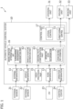
- an automatic vehicle-control system 10 constituting the driving control apparatus of a vehicle 1 includes an external information acquisition part 11, a vehicle information acquisition part 12, a road information acquisition part 13, a transportation information acquisition part 14, a high-precision map 15, a driving operation determination unit 16, and a control unit 17.
- the external information acquisition part 11 extracts information required for the driving operation determination unit 16 from data received from an external sensor 21 composed of multiple sensors, and processes the information in a format for surrounding environment recognition (lane recognition, road structure recognition, mobile object detection, signal/road sign recognition). The series of processing steps is performed at a predetermined time rate, and the information is updated and is stored in a storage device.
- lane recognition road structure recognition
- mobile object detection signal/road sign recognition
- the external sensor 21 includes a LiDAR for detecting mobile objects (e.g., a vehicle, a bicycle, and a pedestrian) around the vehicle, stationary objects (e.g., an obstacle and a stopped vehicle), road structures (e.g., a curb, a median strip, a guardrail, a traffic signal, and a crossing gate), and structures (e.g., an external wall, a utility pole, and a tree), a radar (a millimeter wave radar, an infrared radar), a camera (an image sensor such as a monocular camera or a stereo camera), a GNSS (satellite positioning system) for detecting the position of the vehicle, and an acceleration sensor and a gyroscope sensor that detect the three-dimensional movement and orientation of the vehicle or an IMU (inertial measurement unit) as a combination of the sensors.
- a LiDAR for detecting mobile objects (e.g., a vehicle, a bicycle, and a pedestrian) around the vehicle, stationary objects (e.g
- the vehicle information acquisition part 12 acquires, via intra-vehicle communications (in-vehicle network), a detected value of an internal sensor 22 including sensors such as a vehicle speed sensor, an acceleration sensor, a yaw rate sensor, a steering angle sensor, an accelerator sensor, and a brake sensor that determine the state of motion of the vehicle 1, extracts information necessary for the driving operation determination unit 16 according to each purpose of control, and processes the information in a format usable by the driving operation determination unit 16.
- the series of processing steps is performed at a predetermined time rate, and the information is updated and is stored in the storage device.
- the road information acquisition part 13 extracts information necessary for the driving operation determination unit 16 from data that is distributed from a communication infrastructure (roadside infrastructure) built on a road and is received via an I2V receiver 23 through broadcast information distribution, V2I road/automobile communications, and mobile communications using a cellular communication network, the data including, for example, signal information at an intersection, information about surrounding vehicles, and traffic information including lane restrictions and regulation speeds in relation to position information.
- the road information acquisition part 13 then processes the information in a format usable by the driving operation determination unit 16. The series of processing steps is performed at a predetermined time rate, and the information is updated and is stored in the storage device.
- the operation information acquisition part 14 extracts information necessary for the driving operation determination unit 16 from, for example, data received through mobile communications with a control center 24 of the self-driving vehicle 1, path update information, reservation information such as a pickup and drop-off point and time, user information, and authentication information.
- the operation information acquisition part 14 then processes the information in a format usable by the driving operation determination unit 16 according to each purpose. The series of processing steps is performed at a predetermined time rate, and the information is updated and is stored in the storage device.
- the control center 24 is a control center for supervising the transportation service provided by the self-driving vehicle 1.
- the control center 24 manages the overall transportation service at, for example, the current position of the self-driving vehicle 1 and communicates information with each self-driving vehicle.
- the high-precision map 15 is a map system (database) having a multilevel data hierarchy including information necessary for automated driving, for example, position information about a road network covering the driving area of the self-driving vehicle 1, three-dimensional information about road structures, surrounding structures, and trees, driving lane information, regulation information including regulation speeds, parking prohibition, and overtaking (passing) prohibition, and the presence or absence of an accessible zone into a roadway.
- map system database having a multilevel data hierarchy including information necessary for automated driving, for example, position information about a road network covering the driving area of the self-driving vehicle 1, three-dimensional information about road structures, surrounding structures, and trees, driving lane information, regulation information including regulation speeds, parking prohibition, and overtaking (passing) prohibition, and the presence or absence of an accessible zone into a roadway.
- the accessible zone (that is, an alert zone) as a criterion of driving modes (alert mode 1, alert mode 2), which will be described later, is determined by, for example, the presence or absence of a structure (e.g., a guardrail, a plant, or a curb) between a roadway and a sidewalk, the height of the structure, and intervals and spacings between structures. For example, if there is a guardrail having a height of 50 cm or more, entry is impossible (not an inaccessible zone), and if a spacing between a utility pole and a guardrail is less than a predetermined value (e.g., 30 cm), entry is impossible (not an accessible zone).
- a predetermined value e.g. 30 cm
- Figure 3 illustrates a road structure example including accessible zones 56 and 57.
- guardrails 53, 54, and 55 are discontinuously provided at a boundary portion between a sidewalk 50 and a road 5 that includes a first lane 51 and a second lane 52.
- the accessible zones 56 and 57 where pedestrians may enter to the roadway 5 (51) from the sidewalk 50 are formed between the guardrails.
- the driving operation determination unit 16 includes a unit that performs processing including the surrounding environment recognition, vehicle position estimation, and path planning of the self-driving vehicle 1 and determines a target path based on a global path (a route or a global path) based on a predetermined driving plan and a local path corresponding to a driving mode specified according to a road environment near the vehicle and the operation conditions.
- a surrounding environment recognition part 61 combines external information acquired by the external information acquisition part 11, specifically, information about mobile objects (e.g., a vehicle, a bicycle, and a pedestrian) around the vehicle, stationary objects (e.g., an obstacle and a stopped vehicle), road structures (e.g., a curb, a median strip, a guardrail, a traffic signal, and a crossing gate), and structures (e.g., an external wall, a utility pole, and a tree) and performs surrounding environment recognition (lane recognition, road structure recognition, mobile object detection, signal/road sign recognition) processing of the self-driving vehicle 1.
- mobile objects e.g., a vehicle, a bicycle, and a pedestrian
- stationary objects e.g., an obstacle and a stopped vehicle
- road structures e.g., a curb, a median strip, a guardrail, a traffic signal, and a crossing gate
- structures e.g., an external wall, a utility pole, and a tree
- a vehicle position estimation part 62 estimates the position (e.g., coordinate values X, Y, Z and latitude/longitude) of the self-driving vehicle 1 on a map and the traveling direction (yaw angle) of the self-driving vehicle 1.
- Usable methods of estimation are an estimation method including matching of the measurement points of a LiDAR constituting the external sensor 21 and the points of the high-precision map 15 (for example, NDT matching (Normal Distribution Transform)), an estimation method including matching of feature points extracted from a camera image and the points of the high-precision map 15 (for example, Visual SLAM "Simultaneous Localization and Mapping"), a method of estimation from a latitude and a longitude that are detected by a GNSS, and a method of estimation from a vehicle movement and rotation that are determined from a vehicle speed and a yaw rate (for example, Dead Reckoning).
- NDT matching Normal Distribution Transform
- an estimation method including matching of feature points extracted from a camera image and the points of the high-precision map 15 for example, Visual SLAM "Simultaneous Localization and Mapping"
- a method of estimation from a latitude and a longitude that are detected by a GNSS for example, a method of
- a driving path configuration part 63 determines a target path for the self-driving vehicle 1 based on the determined position and orientation of the self-driving vehicle 1 by the vehicle position estimation part 62 and the surrounding environment recognized by the surrounding environment recognition part 61 and according to the driving mode determined by an operating state determination part 64.
- the operating state determination part 64 selects one of a normal driving mode, the alert mode 1, and the alert mode 2 according to the surrounding environment and the operation conditions of the self-driving vehicle 1. Criteria for determining the driving mode include operation conditions such as the presence or absence of passengers, whether transportation service is being offered, whether the vehicle is driven in a fixed-time and fixed-route operation in addition to the presence or absence of the accessible zone, and lane change conditions such as the presence or absence of an adjacent lane and the presence or absence of a vehicle traveling in a predetermined region of an adjacent lane.
- the driving modes are set as follows:
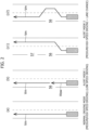
- the vehicle travels at a medium/high set speed (Vm) while keeping in the first lane (left lane).
- Vm medium/high set speed
- the vehicle follows the preceding vehicle while keeping a set intervehicle time between the vehicles.
- the vehicle travels at a low set speed (Vlow) while keeping in the first lane (left side), thereby preparing for the entry of another traffic participant into the lane of the vehicle to avoid a collision with the traffic participant. Also in this case, in the presence of a vehicle preceding at the set speed or less, the vehicle follows the preceding vehicle while keeping a set inter-vehicle time between the vehicles.
- the vehicle moves to the second lane (right lane) remote from the accessible zone (56) and travels at the medium/high set speed (Vm). Also in this case, in the presence of a vehicle preceding at the set speed or less, the vehicle follows the preceding vehicle while keeping a set inter-vehicle time between the vehicles.
- a transportation-mode path generation part 65 generates a driving path from a driving vehicle speed pattern for keeping in the first lane, a path and a driving vehicle speed pattern for a lane change to the second lane, and a path and a vehicle speed pattern for a lane change from the second lane to the first lane according to the driving mode (one of the normal driving mode, the alert mode 1, and the alert mode 2) selected by the operating state determination part 64.
- a path is set at a transition to the alert mode 2 such that the vehicle moves to the second lane (right lane), travels over a certain section (predetermined time), and then returns to the first lane (left lane) as illustrated in Figure 2(c2) .
- the vehicle when the accessible zones (56, 57) are consecutive with a short interval less than a predetermined distance D, the vehicle further travels on the second lane (right lane) over a certain section (predetermined time), moves to the first lane (left lane), and then returns to the normal driving mode.
- the vehicle may continue to travel at the low set speed (Vlow) and return to the normal driving mode in the absence of an accessible zone.
- the predetermined distance D for determining the continuation of the alert mode 1 can be equal to or less than the predetermined distance D for determining the continuation of the alert mode 2.
- the control unit 17 includes a lateral control unit 71 that outputs a steering angle command to a steering unit 31, the steering angle command indicating a target steering angle for causing the vehicle 1 to follow the target path determined by the driving operation determination unit 16, and a longitudinal control unit 72 that outputs a speed command (acceleration/deceleration command) for achieving a target speed, to a driving unit 32 and a braking unit 33.
- a lateral control unit 71 that outputs a steering angle command to a steering unit 31, the steering angle command indicating a target steering angle for causing the vehicle 1 to follow the target path determined by the driving operation determination unit 16, and a longitudinal control unit 72 that outputs a speed command (acceleration/deceleration command) for achieving a target speed, to a driving unit 32 and a braking unit 33.
- Each of the units constituting the automatic vehicle-control system 10 described above is implemented as a computer (ECU) including ROM that stores programs operable to execute the functions, a CPU that performs arithmetic processing, RAM reading the programs and serving as a work area of the CPU and a temporary storage of operation results, and an input/output interface.
- ECU computer
- the steering unit 31 is composed of a steering mechanism including a steering wheel, and a steering actuator (an ESP motor constituting an electric power steering system).
- the driving unit 32 includes an internal combustion engine and an engine controller in an internal combustion engine vehicle, includes a motor generator and a motor controller in an electric motor vehicle, and includes these components and a hybrid controller in a hybrid vehicle.
- the braking unit 33 includes a braking device for braking each wheel, a brake actuator, and a brake controller (ESC controller).
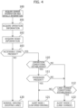
- Figure 4 is a flowchart showing a flow of operating state determination according to a first embodiment. During the driving of the vehicle 1, such determining operations are sequentially performed at a predetermined time rate.
- sensor information and vehicle information are acquired as a basis for determination from the external information acquisition part 11 and the vehicle information acquisition part 12, the information is verified against the map information of the high-precision map 15 by surrounding environment recognition and vehicle position estimation, and then a road structure ahead of the vehicle, surrounding vehicles, and traffic participants are monitored (step 100).
- step 101 operation information acquired by the operation information acquisition part 14 is referred to (step 101), and road information acquired by the road information acquisition part 13 is referred to (step 102).
- the normal driving mode is selected to continue driving in the normal driving mode (step 120).
- step 103; YES In the presence of an accessible zone on the driving course ahead of the vehicle (step 103; YES), whether the operation conditions (transportation service operation conditions) of the vehicle 1 are established is checked. If the service operation conditions such as driving in a fixed-time and fixed-route operation and ongoing operation service are established (step 110; YES) and the vehicle carries passengers (step 111; YES), the alert mode 1 is selected and the vehicle shifts to low-speed driving while keeping in the lane (step 121).
- the service operation conditions such as driving in a fixed-time and fixed-route operation and ongoing operation service
- step 110 If the operation conditions (service operation conditions) are not established (step 110; NO), for example, when the vehicle 1 is out of service or if lane change conditions are established (step 112; YES), for example, if the service operation conditions are established (step 110; YES) but the vehicle 1 carries no passengers (step 111; NO) in the absence of another vehicle in a predetermined range of an adjacent lane, the alert mode 2 is selected and the lane is changed to the second lane after the blinker is turned on (step 122).
- step 112 if the lane change conditions are not established (step 112; NO), for example, in the presence of another vehicle in a predetermined range of an adjacent lane, the alert mode 1 is selected and the vehicle shifts to low-speed driving while keeping in the lane (step 121).
- a mode change should be prohibited for a predetermined time to prevent it affecting driving control.
- Transportation service vehicles are provided in several operating forms, for example, on-demand vehicles like a taxi are available in addition to vehicles driven in fixed-time and fixed-route operations, for example, a regular-route bus.
- on-demand vehicles like a taxi
- fixed-time and fixed-route operations for example, a regular-route bus.
- shared taxis ride share taxis
- the determination conditions may be changed depending on the operating form.
- the alert mode 2 is selected as in the case of an out-of-service vehicle.
- the alert mode 1 may be selected regardless of the presence or absence of a passenger.
- FIG. 5 is a flowchart showing a flow of operating state determination according to a second embodiment.
- the basic flow of steps 100 to 103 is identical to that of the first embodiment.
- a scoring table is set in advance such that a weight is assigned to each of the conditions.
- (Transportation conditions) YES
- the scores of the operation conditions are totaled (step 114). If the total score is less than a predetermined threshold value (e.g., 0) (step 115; YES), the alert mode 1 is selected (step 121). If the total score is equal to or greater than the predetermined threshold value (e.g., 0) (step 115; NO), the alert mode 2 is selected (step 122).
- a predetermined threshold value e.g., 0
- the alert mode 2 is selected (step 122).
- road environment conditions are added in addition to the operation conditions. Conditions can be further added as appropriate depending on the form of transportation, such as a time zone, weather, the presence or absence and amount of delay of an operating time (fixed-time and fixed-route), and the presence or absence of a reservation for loading or unloading at the next stop (shared taxi).
- the driving control apparatus for a vehicle performs a first alert mode, in which a vehicle drives at a low speed while keeping in a lane during a service operation, in the presence of an accessible zone ahead of the vehicle, thereby preventing unease and decline in the comfort of passengers while preparing for an unexpected entry of a traffic participant into a driving path.
- the driving control apparatus performs a second alert mode, in which when a lane change is allowed, a vehicle moves to another lane remote from an accessible zone while maintaining speed, thereby preventing reduction in efficiency of a vehicle that is not in service and the delivery efficiency of the vehicle while preparing for an unexpected entry of a traffic participant into a driving path.
- Pedestrians are handled in the alert modes 1 and 2 in consideration of a road structure and transportation conditions, so that the computation load can be lighter than that of separate handling from an alert level and the system resource can be used for other processing, for example, obstacle detection or surrounding environment recognition.
- the second alert mode is performed when the lane change conditions are established, thereby properly maintaining the efficiency of a deadhead vehicle and the delivery efficiency of the vehicle while preparing for an unexpected entry of a traffic participant into a driving path.
- the first alert mode is performed when a driving section has a lower speed limit than normal driving, thereby preventing unease and decrease in the comfort of passengers while preparing for an unexpected entry of a traffic participant into a driving path.
Landscapes
- Engineering & Computer Science (AREA)
- Automation & Control Theory (AREA)
- Transportation (AREA)
- Mechanical Engineering (AREA)
- Human Computer Interaction (AREA)
- Physics & Mathematics (AREA)
- Mathematical Physics (AREA)
- Traffic Control Systems (AREA)
Abstract
Description
- The present invention relates to a driving control apparatus for a transportation service vehicle, in particular, a driving control apparatus for a self-driving vehicle for a transportation service.
- Transportation services using self-driving vehicles have been proposed in various forms, e.g., fixed-time and fixed-route service, on-demand service, and fixed-route and on-demand service. A driving path for a self-driving vehicle is determined by combining a predetermined global path (e.g., a route from a starting point to a goal point) and a local path (e.g., obstacle avoidance, a temporary lane change, and stop and start at an intersection) determined according to a road environment near the vehicle. For example, if a traffic participant (a mobile object; a vehicle, a pedestrian, a bicycle or the like) is recognized around the vehicle and is predicted to become an obstacle, the vehicle is required to take evasive action such as changing path or stopping.
- Among traffic participants, vehicles travel according to driving lanes, which are specified by lane markings or road structures, and traffic regulations, and thus vehicles, are not present as obstacles like a stopped vehicle. A vehicle ahead is not immediately recognized as an obstacle if an inter-vehicular distance from the vehicle ahead is maintained. However, in the case of pedestrians, it is more difficult to predict the behavior of the pedestrians than that of vehicles, and it is also difficult to determine whether a pedestrian is likely to be an obstacle, even though passage lanes such as a walkway and a sidewalk are provided.
-
Patent Literature 1 discloses that a risk region (risk potential) is set for a traffic participant (a pedestrian) recognized by the recognition unit, the risk region is corrected based on target environments such as the width of a sidewalk and the width of a roadway and the attributes of traffic participants, and vehicle speed control and steering control are performed based on the corrected risk region. - [Patent Literature 1]
JP 2021-149390 A - In a method for setting a risk region for a traffic participant (a pedestrian), evaluation targets to be reflected in control are finally reduced by correcting the risk region based on a target environment. However, targets to be processed with set risk regions are not reduced, so that computation load may increase with the awareness or the population of traffic participants.
- Furthermore, if actions are taken against individual traffic participants at an alert level and driving paths are changed for each action, surrounding vehicles may be affected, and feelings of security and comfort of passengers and staff members may also be affected. In particular, in vehicles based on passenger services like transportation service vehicles, growing unease and decrease in comfort of passengers may become problems to be solved first.
- The present invention has been devised in view of such circumstances. An object of the present invention is to provide a driving control apparatus for a transportation service vehicle, the driving control apparatus adapting to the operating mode of the transportation service vehicle, being capable of preventing unease and decrease in comfort of passengers while preparing for an unexpected entry of a traffic participant into a driving path, and the required computational load is small.
- In order to solve the problem, the present invention is a driving control apparatus for a transportation service vehicle, the driving control apparatus comprising: a driving operation determination unit that determines a target path based on a predetermined global path and a road environment near the vehicle; and a control unit that performs speed control and steering control such that the vehicle follows the target path, wherein
- the driving operation determination unit is prepared to, when an accessible zone from which other traffic participants may enter is present on a driving course ahead of the vehicle, selectively perform a first alert mode in which the vehicle travels at a lower speed than in normal driving while keeping in the lane, or a second alert mode in which the vehicle changes to a lane away from the accessible zone while maintaining a normal driving speed, and configured to
- perform the second alert mode if predetermined lane change conditions are established when a service operation is not being performed, and
- perform the first alert mode if the service operation is being performed or the predetermined lane change conditions are not established.
- As described above, the driving control apparatus for a vehicle according to the present invention performs the first alert mode, in which the vehicle travels at a lower speed while keeping in a lane during a service operation, in the presence of the accessible zone ahead of the vehicle, thereby preventing unease and decrease in the comfort of passengers while preparing for an unexpected entry of a traffic participant into a driving path. On the other hand, when a service operation is not being performed, the driving control apparatus performs the second alert mode, in which when a lane change is possible, the vehicle changes to a lane away from the accessible zone while maintaining the speed, thereby maintaining efficiency of a vehicle that is not in service while preparing for an unexpected entry of a traffic participant into a driving path. By not dealing with pedestrians whose behavior is difficult to predict individually based on the alert level, but dealing with them in a driving mode (alert mode) that takes into account road structure and driving conditions, this advantageously reduces computational load compared to dealing with pedestrians individually in an alert level.
-
- [
Figure 1] Figure 1 is a block diagram illustrating the outline of an automatic vehicle-control system. - [
Figure 2] Figure 2(a) is a schematic drawing of driving in a normal driving mode,Figure 2(b) is a schematic drawing of driving in a first alert mode, andFigures 2(c1) and 2(c2) are schematic drawings of driving in a second alert mode. - [
Figure 3] Figure 3 is a perspective view illustrating an example of an accessible zone on one side of a road. - [
Figure 4] Figure 4 is a flowchart showing a flow of operating state determination according to a first embodiment. - [
Figure 5] Figure 5 is a flowchart showing a flow of operating state determination according to a second embodiment. - Embodiments according to the present invention will be specifically described below with reference to the accompanying drawings.
- As illustrated in
Figure 1 , an automatic vehicle-control system 10 constituting the driving control apparatus of avehicle 1 according to an embodiment of the present invention includes an externalinformation acquisition part 11, a vehicleinformation acquisition part 12, a roadinformation acquisition part 13, a transportationinformation acquisition part 14, a high-precision map 15, a drivingoperation determination unit 16, and acontrol unit 17. - The external
information acquisition part 11 extracts information required for the drivingoperation determination unit 16 from data received from anexternal sensor 21 composed of multiple sensors, and processes the information in a format for surrounding environment recognition (lane recognition, road structure recognition, mobile object detection, signal/road sign recognition). The series of processing steps is performed at a predetermined time rate, and the information is updated and is stored in a storage device. - The
external sensor 21 includes a LiDAR for detecting mobile objects (e.g., a vehicle, a bicycle, and a pedestrian) around the vehicle, stationary objects (e.g., an obstacle and a stopped vehicle), road structures (e.g., a curb, a median strip, a guardrail, a traffic signal, and a crossing gate), and structures (e.g., an external wall, a utility pole, and a tree), a radar (a millimeter wave radar, an infrared radar), a camera (an image sensor such as a monocular camera or a stereo camera), a GNSS (satellite positioning system) for detecting the position of the vehicle, and an acceleration sensor and a gyroscope sensor that detect the three-dimensional movement and orientation of the vehicle or an IMU (inertial measurement unit) as a combination of the sensors. - The vehicle
information acquisition part 12 acquires, via intra-vehicle communications (in-vehicle network), a detected value of aninternal sensor 22 including sensors such as a vehicle speed sensor, an acceleration sensor, a yaw rate sensor, a steering angle sensor, an accelerator sensor, and a brake sensor that determine the state of motion of thevehicle 1, extracts information necessary for the drivingoperation determination unit 16 according to each purpose of control, and processes the information in a format usable by the drivingoperation determination unit 16. The series of processing steps is performed at a predetermined time rate, and the information is updated and is stored in the storage device. - The road
information acquisition part 13 extracts information necessary for the drivingoperation determination unit 16 from data that is distributed from a communication infrastructure (roadside infrastructure) built on a road and is received via anI2V receiver 23 through broadcast information distribution, V2I road/automobile communications, and mobile communications using a cellular communication network, the data including, for example, signal information at an intersection, information about surrounding vehicles, and traffic information including lane restrictions and regulation speeds in relation to position information. The roadinformation acquisition part 13 then processes the information in a format usable by the drivingoperation determination unit 16. The series of processing steps is performed at a predetermined time rate, and the information is updated and is stored in the storage device. - The operation
information acquisition part 14 extracts information necessary for the drivingoperation determination unit 16 from, for example, data received through mobile communications with acontrol center 24 of the self-drivingvehicle 1, path update information, reservation information such as a pickup and drop-off point and time, user information, and authentication information. The operationinformation acquisition part 14 then processes the information in a format usable by the drivingoperation determination unit 16 according to each purpose. The series of processing steps is performed at a predetermined time rate, and the information is updated and is stored in the storage device. - The
control center 24 is a control center for supervising the transportation service provided by the self-drivingvehicle 1. Thecontrol center 24 manages the overall transportation service at, for example, the current position of the self-drivingvehicle 1 and communicates information with each self-driving vehicle. - The high-
precision map 15 is a map system (database) having a multilevel data hierarchy including information necessary for automated driving, for example, position information about a road network covering the driving area of the self-drivingvehicle 1, three-dimensional information about road structures, surrounding structures, and trees, driving lane information, regulation information including regulation speeds, parking prohibition, and overtaking (passing) prohibition, and the presence or absence of an accessible zone into a roadway. - The accessible zone (that is, an alert zone) as a criterion of driving modes (
alert mode 1, alert mode 2), which will be described later, is determined by, for example, the presence or absence of a structure (e.g., a guardrail, a plant, or a curb) between a roadway and a sidewalk, the height of the structure, and intervals and spacings between structures. For example, if there is a guardrail having a height of 50 cm or more, entry is impossible (not an inaccessible zone), and if a spacing between a utility pole and a guardrail is less than a predetermined value (e.g., 30 cm), entry is impossible (not an accessible zone). -
Figure 3 illustrates a road structure example includingaccessible zones guardrails sidewalk 50 and aroad 5 that includes afirst lane 51 and asecond lane 52. Theaccessible zones sidewalk 50 are formed between the guardrails. These determinations are set and updated based on external information acquired by the externalinformation acquisition part 11 in addition to map information of the high-precision map 15. - The driving
operation determination unit 16 includes a unit that performs processing including the surrounding environment recognition, vehicle position estimation, and path planning of the self-drivingvehicle 1 and determines a target path based on a global path (a route or a global path) based on a predetermined driving plan and a local path corresponding to a driving mode specified according to a road environment near the vehicle and the operation conditions. - A surrounding
environment recognition part 61 combines external information acquired by the externalinformation acquisition part 11, specifically, information about mobile objects (e.g., a vehicle, a bicycle, and a pedestrian) around the vehicle, stationary objects (e.g., an obstacle and a stopped vehicle), road structures (e.g., a curb, a median strip, a guardrail, a traffic signal, and a crossing gate), and structures (e.g., an external wall, a utility pole, and a tree) and performs surrounding environment recognition (lane recognition, road structure recognition, mobile object detection, signal/road sign recognition) processing of the self-drivingvehicle 1. - A vehicle
position estimation part 62 estimates the position (e.g., coordinate values X, Y, Z and latitude/longitude) of the self-drivingvehicle 1 on a map and the traveling direction (yaw angle) of the self-drivingvehicle 1. Usable methods of estimation are an estimation method including matching of the measurement points of a LiDAR constituting theexternal sensor 21 and the points of the high-precision map 15 (for example, NDT matching (Normal Distribution Transform)), an estimation method including matching of feature points extracted from a camera image and the points of the high-precision map 15 (for example, Visual SLAM "Simultaneous Localization and Mapping"), a method of estimation from a latitude and a longitude that are detected by a GNSS, and a method of estimation from a vehicle movement and rotation that are determined from a vehicle speed and a yaw rate (for example, Dead Reckoning). - A driving
path configuration part 63 determines a target path for the self-drivingvehicle 1 based on the determined position and orientation of the self-drivingvehicle 1 by the vehicleposition estimation part 62 and the surrounding environment recognized by the surroundingenvironment recognition part 61 and according to the driving mode determined by an operatingstate determination part 64. - The operating
state determination part 64 selects one of a normal driving mode, thealert mode 1, and thealert mode 2 according to the surrounding environment and the operation conditions of the self-drivingvehicle 1. Criteria for determining the driving mode include operation conditions such as the presence or absence of passengers, whether transportation service is being offered, whether the vehicle is driven in a fixed-time and fixed-route operation in addition to the presence or absence of the accessible zone, and lane change conditions such as the presence or absence of an adjacent lane and the presence or absence of a vehicle traveling in a predetermined region of an adjacent lane. The driving modes are set as follows: - In the normal driving mode, as illustrated in
Figure 2(a) , the vehicle travels at a medium/high set speed (Vm) while keeping in the first lane (left lane). In the presence of a vehicle preceding at a set speed or less, the vehicle follows the preceding vehicle while keeping a set intervehicle time between the vehicles. - In the
alert mode 1, as illustrated inFigure 2(b) , when an accessible zone (56) is present ahead of the vehicle and predetermined transition conditions are established, the vehicle travels at a low set speed (Vlow) while keeping in the first lane (left side), thereby preparing for the entry of another traffic participant into the lane of the vehicle to avoid a collision with the traffic participant. Also in this case, in the presence of a vehicle preceding at the set speed or less, the vehicle follows the preceding vehicle while keeping a set inter-vehicle time between the vehicles. - In the
alert mode 2, as illustrated inFigures 2(c1) and 2(c2) , when an accessible zone is present ahead of the vehicle and predetermined transition conditions are established, the vehicle moves to the second lane (right lane) remote from the accessible zone (56) and travels at the medium/high set speed (Vm). Also in this case, in the presence of a vehicle preceding at the set speed or less, the vehicle follows the preceding vehicle while keeping a set inter-vehicle time between the vehicles. - A transportation-mode
path generation part 65 generates a driving path from a driving vehicle speed pattern for keeping in the first lane, a path and a driving vehicle speed pattern for a lane change to the second lane, and a path and a vehicle speed pattern for a lane change from the second lane to the first lane according to the driving mode (one of the normal driving mode, thealert mode 1, and the alert mode 2) selected by the operatingstate determination part 64. - Basically, in the
alert mode 2, a path is set at a transition to thealert mode 2 such that the vehicle moves to the second lane (right lane), travels over a certain section (predetermined time), and then returns to the first lane (left lane) as illustrated inFigure 2(c2) . However, as illustrated inFigure 2(c1) , when the accessible zones (56, 57) are consecutive with a short interval less than a predetermined distance D, the vehicle further travels on the second lane (right lane) over a certain section (predetermined time), moves to the first lane (left lane), and then returns to the normal driving mode. - Furthermore, although not shown in the Figure, even in the
alert mode 1, when the accessible zones (56, 57) are consecutive with a short interval less than a predetermined distance D, the vehicle may continue to travel at the low set speed (Vlow) and return to the normal driving mode in the absence of an accessible zone. In this case, the predetermined distance D for determining the continuation of thealert mode 1 can be equal to or less than the predetermined distance D for determining the continuation of thealert mode 2. - The
control unit 17 includes alateral control unit 71 that outputs a steering angle command to asteering unit 31, the steering angle command indicating a target steering angle for causing thevehicle 1 to follow the target path determined by the drivingoperation determination unit 16, and alongitudinal control unit 72 that outputs a speed command (acceleration/deceleration command) for achieving a target speed, to a drivingunit 32 and abraking unit 33. - Each of the units constituting the automatic vehicle-
control system 10 described above is implemented as a computer (ECU) including ROM that stores programs operable to execute the functions, a CPU that performs arithmetic processing, RAM reading the programs and serving as a work area of the CPU and a temporary storage of operation results, and an input/output interface. - The
steering unit 31 is composed of a steering mechanism including a steering wheel, and a steering actuator (an ESP motor constituting an electric power steering system). The drivingunit 32 includes an internal combustion engine and an engine controller in an internal combustion engine vehicle, includes a motor generator and a motor controller in an electric motor vehicle, and includes these components and a hybrid controller in a hybrid vehicle. Thebraking unit 33 includes a braking device for braking each wheel, a brake actuator, and a brake controller (ESC controller). -
Figure 4 is a flowchart showing a flow of operating state determination according to a first embodiment. During the driving of thevehicle 1, such determining operations are sequentially performed at a predetermined time rate. - First, sensor information and vehicle information are acquired as a basis for determination from the external
information acquisition part 11 and the vehicleinformation acquisition part 12, the information is verified against the map information of the high-precision map 15 by surrounding environment recognition and vehicle position estimation, and then a road structure ahead of the vehicle, surrounding vehicles, and traffic participants are monitored (step 100). - In addition, operation information acquired by the operation
information acquisition part 14 is referred to (step 101), and road information acquired by the roadinformation acquisition part 13 is referred to (step 102). - In the absence of an accessible zone on a driving course ahead of the vehicle (
step 103; NO), the normal driving mode is selected to continue driving in the normal driving mode (step 120). - In the presence of an accessible zone on the driving course ahead of the vehicle (
step 103; YES), whether the operation conditions (transportation service operation conditions) of thevehicle 1 are established is checked. If the service operation conditions such as driving in a fixed-time and fixed-route operation and ongoing operation service are established (step 110; YES) and the vehicle carries passengers (step 111; YES), thealert mode 1 is selected and the vehicle shifts to low-speed driving while keeping in the lane (step 121). - If the operation conditions (service operation conditions) are not established (
step 110; NO), for example, when thevehicle 1 is out of service or if lane change conditions are established (step 112; YES), for example, if the service operation conditions are established (step 110; YES) but thevehicle 1 carries no passengers (step 111; NO) in the absence of another vehicle in a predetermined range of an adjacent lane, thealert mode 2 is selected and the lane is changed to the second lane after the blinker is turned on (step 122). - In addition, if the lane change conditions are not established (
step 112; NO), for example, in the presence of another vehicle in a predetermined range of an adjacent lane, thealert mode 1 is selected and the vehicle shifts to low-speed driving while keeping in the lane (step 121). - As described above, in order to avoid repetition of speed changes during a shift to the
alert mode 1 or lane changes during a shift to thealert mode 2 in a short period, driving in thealert mode alert mode - Transportation service vehicles are provided in several operating forms, for example, on-demand vehicles like a taxi are available in addition to vehicles driven in fixed-time and fixed-route operations, for example, a regular-route bus. In addition, shared taxis (ride share taxis) are provided as an intermediate operating form. The determination conditions may be changed depending on the operating form.
- For example, in the absence of a passenger in a fixed-time and fixed-route operation in the embodiment described above, the
alert mode 2 is selected as in the case of an out-of-service vehicle. When the operation conditions are established, thealert mode 1 may be selected regardless of the presence or absence of a passenger. -
Figure 5 is a flowchart showing a flow of operating state determination according to a second embodiment. The basic flow ofsteps 100 to 103 is identical to that of the first embodiment. For the determination of thealert modes (Transportation conditions) (YES) (NO) Service operation -3 +2 Fixed-time and fixed-route operation -2 +2 Presence of a passenger -1 +1 Presence of a rear vehicle -1 +1 Presence of a speed limit -1 +1 - In the presence of an accessible zone on a driving course ahead of the vehicle (
step 103; YES), the scores of the operation conditions are totaled (step 114). If the total score is less than a predetermined threshold value (e.g., 0) (step 115; YES), thealert mode 1 is selected (step 121). If the total score is equal to or greater than the predetermined threshold value (e.g., 0) (step 115; NO), thealert mode 2 is selected (step 122). - In this embodiment, road environment conditions are added in addition to the operation conditions. Conditions can be further added as appropriate depending on the form of transportation, such as a time zone, weather, the presence or absence and amount of delay of an operating time (fixed-time and fixed-route), and the presence or absence of a reservation for loading or unloading at the next stop (shared taxi).
- As described above, the driving control apparatus for a vehicle according to the present invention performs a first alert mode, in which a vehicle drives at a low speed while keeping in a lane during a service operation, in the presence of an accessible zone ahead of the vehicle, thereby preventing unease and decline in the comfort of passengers while preparing for an unexpected entry of a traffic participant into a driving path.
- In addition, when a service operation is not being performed, the driving control apparatus performs a second alert mode, in which when a lane change is allowed, a vehicle moves to another lane remote from an accessible zone while maintaining speed, thereby preventing reduction in efficiency of a vehicle that is not in service and the delivery efficiency of the vehicle while preparing for an unexpected entry of a traffic participant into a driving path.
- In addition, pedestrians are not separately handled at an alert level because the actions of pedestrians are difficult to predict. Pedestrians are handled in the
alert modes - In the absence of passengers during a service operation, the comfort of passengers does not need to be considered. Thus, the second alert mode is performed when the lane change conditions are established, thereby properly maintaining the efficiency of a deadhead vehicle and the delivery efficiency of the vehicle while preparing for an unexpected entry of a traffic participant into a driving path.
- In addition, even if a service operation is not performed and the lane change conditions are established, the first alert mode is performed when a driving section has a lower speed limit than normal driving, thereby preventing unease and decrease in the comfort of passengers while preparing for an unexpected entry of a traffic participant into a driving path.
- The embodiments of the present invention were described in the foregoing description. The present invention is not limited to the embodiments described above, and the can be modified and changed in various ways within the scope of the claims of the present invention based on the technical idea of the present invention.
-
- 1
- Vehicle
- 5
- Road
- 10
- Automatic vehicle-control system
- 11
- External information acquisition part
- 12
- Vehicle information acquisition part
- 13
- Road information acquisition part
- 14
- Operation information acquisition part
- 15
- High-precision map
- 16
- Driving operation determination unit
- 17
- Control unit
- 21
- External sensor
- 22
- Internal sensor
- 23
- I2V receiver
- 24
- Control center
- 31
- Steering unit
- 32
- Driving unit
- 33
- Braking unit
- 50
- Sidewalk (Road side space)
- 51
- First lane
- 52
- Second lane
- 53, 54, 55
- Guardrail
- 56, 57
- Accessible zone
- 61
- Surrounding environment recognition part
- 62
- Vehicle position estimation part
- 63
- Driving path configuration part
- 64
- Operating state determination part
- 65
- Operation-mode path generation part
Claims (6)
- A driving control apparatus for a transportation service vehicle, the driving control apparatus comprising: a driving operation determination unit that determines a target path based on a predetermined global path and a road environment near the vehicle; and a control unit that performs speed control and steering control such that the vehicle follows the target path, whereinthe driving operation determination unit is prepared to, when an accessible zone from which other traffic participants may enter is present on a driving course ahead of the vehicle, selectively perform a first alert mode in which the vehicle travels at a lower speed than in normal driving while keeping in the lane, or a second alert mode in which the vehicle changes to a lane away from the accessible zone while maintaining a normal driving speed, and configured toperform the second alert mode if predetermined lane change conditions are established when a service operation is not being performed, andperform the first alert mode if the service operation is being performed or the predetermined lane change conditions are not established.
- The driving control apparatus according to claim 1, wherein if the lane change conditions are established in absence of passengers even during a service operation, the second alert mode is performed.
- The driving control apparatus according to claim 1, wherein even if the service operation is not being performed and the lane change conditions are established, the first alert mode is performed in a section having a lower speed limit than in normal driving.
- The driving control apparatus according to claim 1, wherein when the vehicle passes the accessible zone in the first alert mode,the first alert mode is terminated to return to normal driving if a distance or an estimated time necessary to reach a subsequent accessible zone is equal to or greater than a first predetermined value, andthe first alert mode is maintained if a distance or an estimated time necessary to reach the subsequent accessible zone is less than the first predetermined value.
- The driving control apparatus according to claim 1, wherein when the vehicle passes the accessible zone in the second alert mode,the vehicle moves to an original lane in view of the lane change conditions and terminates the second alert mode to return to normal driving if a distance or an estimated necessary time to the subsequent accessible zone is equal to or greater than a second predetermined value, andthe second alert mode is maintained if a distance or an estimated time necessary to reach the subsequent accessible zone is less than the second predetermined value.
- A driving control apparatus for a transportation service vehicle, the driving control apparatus comprising: a driving operation determination unit that determines a target path based on a predetermined global path and a road environment near the vehicle; and a control unit that performs speed control and steering control such that the vehicle follows the target path, whereinthe driving operation determination unit is prepared to, when an accessible zone from which other traffic participants may enter is present on a driving course ahead of the vehicle, selectively perform a first alert mode in which the vehicle travels at a lower speed than in normal driving while keeping in the lane, or a second alert mode in which the vehicle changes to a lane away from the accessible zone while maintaining a normal driving speed, and configured toperform the step of summing scores weighted for operation conditions, the operation conditions including at least whether a service operation is being performed, whether the vehicle is driven in a fixed-time and fixed-route operation, whether passengers are present or absent, and whether predetermined lane change conditions are established, andperform the second alert mode if a total of the scores is equal to or greater than a predetermined value, and perform the first alert mode if the total of the scores is less than the predetermined value.
Applications Claiming Priority (1)
| Application Number | Priority Date | Filing Date | Title |
|---|---|---|---|
| JP2023194471A JP2025081009A (en) | 2023-11-15 | 2023-11-15 | Travel control device for service vehicles |
Publications (2)
| Publication Number | Publication Date |
|---|---|
| EP4556335A1 true EP4556335A1 (en) | 2025-05-21 |
| EP4556335B1 EP4556335B1 (en) | 2026-01-14 |
Family
ID=93154417
Family Applications (1)
| Application Number | Title | Priority Date | Filing Date |
|---|---|---|---|
| EP24207296.5A Active EP4556335B1 (en) | 2023-11-15 | 2024-10-17 | Driving control apparatus for transportation service vehicle |
Country Status (2)
| Country | Link |
|---|---|
| EP (1) | EP4556335B1 (en) |
| JP (1) | JP2025081009A (en) |
Citations (4)
| Publication number | Priority date | Publication date | Assignee | Title |
|---|---|---|---|---|
| US20200265720A1 (en) * | 2019-02-18 | 2020-08-20 | Toyota Jidosha Kabushiki Kaisha | Dispatch device and dispatching method |
| JP2021149390A (en) | 2020-03-18 | 2021-09-27 | 本田技研工業株式会社 | Vehicle control apparatus, vehicle control method, and program |
| US20210300406A1 (en) * | 2020-03-30 | 2021-09-30 | Toyota Jidosha Kabushiki Kaisha | Automated driving system |
| WO2022093921A1 (en) * | 2020-10-29 | 2022-05-05 | Waymo Llc | Holistic wayfinding |
-
2023
- 2023-11-15 JP JP2023194471A patent/JP2025081009A/en active Pending
-
2024
- 2024-10-17 EP EP24207296.5A patent/EP4556335B1/en active Active
Patent Citations (4)
| Publication number | Priority date | Publication date | Assignee | Title |
|---|---|---|---|---|
| US20200265720A1 (en) * | 2019-02-18 | 2020-08-20 | Toyota Jidosha Kabushiki Kaisha | Dispatch device and dispatching method |
| JP2021149390A (en) | 2020-03-18 | 2021-09-27 | 本田技研工業株式会社 | Vehicle control apparatus, vehicle control method, and program |
| US20210300406A1 (en) * | 2020-03-30 | 2021-09-30 | Toyota Jidosha Kabushiki Kaisha | Automated driving system |
| WO2022093921A1 (en) * | 2020-10-29 | 2022-05-05 | Waymo Llc | Holistic wayfinding |
Also Published As
| Publication number | Publication date |
|---|---|
| EP4556335B1 (en) | 2026-01-14 |
| JP2025081009A (en) | 2025-05-27 |
Similar Documents
| Publication | Publication Date | Title |
|---|---|---|
| CN111746511B (en) | Vehicle control system | |
| CN111819124B (en) | Vehicle control device, vehicle control method and storage medium | |
| CN110356402B (en) | Vehicle control device, vehicle control method, and storage medium | |
| CN112298181B (en) | Vehicle control device, vehicle control method, and storage medium | |
| US11225249B2 (en) | Vehicle control device, vehicle control method, and storage medium | |
| US11167761B2 (en) | Vehicle control device, vehicle control method, and storage medium | |
| CN109070887B (en) | Vehicle control system, vehicle control method, and storage medium | |
| CN112810628A (en) | Vehicle control system | |
| CN110099833B (en) | Vehicle control system, vehicle control method, and storage medium | |
| JP6641583B2 (en) | Vehicle control device, vehicle control method, and program | |
| US20190092333A1 (en) | Vehicle control system, vehicle control method, and vehicle control program | |
| US20190276029A1 (en) | Vehicle control device, vehicle control method, and storage medium | |
| CN110271542B (en) | Vehicle control device, vehicle control method, and storage medium | |
| WO2021261227A1 (en) | Parking/stop point management device, parking/stop point management method, and device for vehicle | |
| JP7606383B2 (en) | Vehicle driving control device | |
| JP6692935B2 (en) | Vehicle control device, vehicle control method, and vehicle control program | |
| CN110087960A (en) | Vehicle control system, control method for vehicle and vehicle control program | |
| CN110087964A (en) | Vehicle control system, vehicle control method, and vehicle control program | |
| CN113460080B (en) | Vehicle control device, vehicle control method and storage medium | |
| JP2022037421A (en) | Vehicle travel control device | |
| US12221103B2 (en) | Vehicle control device, vehicle control method, and storage medium | |
| JP7170637B2 (en) | Vehicle control system, vehicle control method, and program | |
| JP6583697B2 (en) | Perimeter monitoring device, control device, perimeter monitoring method, and program | |
| CN108778881A (en) | Vehicle control system, control method for vehicle and vehicle control program | |
| JP2020083106A (en) | Vehicle control device, vehicle control method and program |
Legal Events
| Date | Code | Title | Description |
|---|---|---|---|
| PUAI | Public reference made under article 153(3) epc to a published international application that has entered the european phase |
Free format text: ORIGINAL CODE: 0009012 |
|
| STAA | Information on the status of an ep patent application or granted ep patent |
Free format text: STATUS: REQUEST FOR EXAMINATION WAS MADE |
|
| 17P | Request for examination filed |
Effective date: 20241017 |
|
| AK | Designated contracting states |
Kind code of ref document: A1 Designated state(s): AL AT BE BG CH CY CZ DE DK EE ES FI FR GB GR HR HU IE IS IT LI LT LU LV MC ME MK MT NL NO PL PT RO RS SE SI SK SM TR |
|
| GRAP | Despatch of communication of intention to grant a patent |
Free format text: ORIGINAL CODE: EPIDOSNIGR1 |
|
| STAA | Information on the status of an ep patent application or granted ep patent |
Free format text: STATUS: GRANT OF PATENT IS INTENDED |
|
| RIC1 | Information provided on ipc code assigned before grant |
Ipc: B60W 30/14 20060101AFI20250930BHEP Ipc: B60W 30/18 20120101ALI20250930BHEP Ipc: B60W 40/04 20060101ALI20250930BHEP Ipc: B60W 50/14 20200101ALI20250930BHEP Ipc: B60W 60/00 20200101ALI20250930BHEP |
|
| INTG | Intention to grant announced |
Effective date: 20251014 |
|
| RIN1 | Information on inventor provided before grant (corrected) |
Inventor name: KUBOTA, HITOSHI |
|
| GRAS | Grant fee paid |
Free format text: ORIGINAL CODE: EPIDOSNIGR3 |
|
| GRAA | (expected) grant |
Free format text: ORIGINAL CODE: 0009210 |
|
| STAA | Information on the status of an ep patent application or granted ep patent |
Free format text: STATUS: THE PATENT HAS BEEN GRANTED |
|
| AK | Designated contracting states |
Kind code of ref document: B1 Designated state(s): AL AT BE BG CH CY CZ DE DK EE ES FI FR GB GR HR HU IE IS IT LI LT LU LV MC ME MK MT NL NO PL PT RO RS SE SI SK SM TR |
|
| REG | Reference to a national code |
Ref country code: CH Ref legal event code: F10 Free format text: ST27 STATUS EVENT CODE: U-0-0-F10-F00 (AS PROVIDED BY THE NATIONAL OFFICE) Effective date: 20260114 Ref country code: GB Ref legal event code: FG4D |
|
| REG | Reference to a national code |
Ref country code: DE Ref legal event code: R096 Ref document number: 602024002061 Country of ref document: DE |
|
| REG | Reference to a national code |
Ref country code: IE Ref legal event code: FG4D |