EP4556320A1 - Air bag device manufacturing method, and air bag device - Google Patents
Air bag device manufacturing method, and air bag device Download PDFInfo
- Publication number
- EP4556320A1 EP4556320A1 EP23857059.2A EP23857059A EP4556320A1 EP 4556320 A1 EP4556320 A1 EP 4556320A1 EP 23857059 A EP23857059 A EP 23857059A EP 4556320 A1 EP4556320 A1 EP 4556320A1
- Authority
- EP
- European Patent Office
- Prior art keywords
- folded
- airbag cushion
- folding
- protruding portion
- protruding
- Prior art date
- Legal status (The legal status is an assumption and is not a legal conclusion. Google has not performed a legal analysis and makes no representation as to the accuracy of the status listed.)
- Pending
Links
Images




Classifications
-
- B—PERFORMING OPERATIONS; TRANSPORTING
- B60—VEHICLES IN GENERAL
- B60R—VEHICLES, VEHICLE FITTINGS, OR VEHICLE PARTS, NOT OTHERWISE PROVIDED FOR
- B60R21/00—Arrangements or fittings on vehicles for protecting or preventing injuries to occupants or pedestrians in case of accidents or other traffic risks
- B60R21/02—Occupant safety arrangements or fittings, e.g. crash pads
- B60R21/16—Inflatable occupant restraints or confinements designed to inflate upon impact or impending impact, e.g. air bags
- B60R21/20—Arrangements for storing inflatable members in their non-use or deflated condition; Arrangement or mounting of air bag modules or components
- B60R21/207—Arrangements for storing inflatable members in their non-use or deflated condition; Arrangement or mounting of air bag modules or components in vehicle seats
-
- B—PERFORMING OPERATIONS; TRANSPORTING
- B60—VEHICLES IN GENERAL
- B60R—VEHICLES, VEHICLE FITTINGS, OR VEHICLE PARTS, NOT OTHERWISE PROVIDED FOR
- B60R21/00—Arrangements or fittings on vehicles for protecting or preventing injuries to occupants or pedestrians in case of accidents or other traffic risks
- B60R21/02—Occupant safety arrangements or fittings, e.g. crash pads
- B60R21/16—Inflatable occupant restraints or confinements designed to inflate upon impact or impending impact, e.g. air bags
- B60R21/23—Inflatable members
- B60R21/231—Inflatable members characterised by their shape, construction or spatial configuration
-
- B—PERFORMING OPERATIONS; TRANSPORTING
- B60—VEHICLES IN GENERAL
- B60R—VEHICLES, VEHICLE FITTINGS, OR VEHICLE PARTS, NOT OTHERWISE PROVIDED FOR
- B60R21/00—Arrangements or fittings on vehicles for protecting or preventing injuries to occupants or pedestrians in case of accidents or other traffic risks
- B60R21/02—Occupant safety arrangements or fittings, e.g. crash pads
- B60R21/16—Inflatable occupant restraints or confinements designed to inflate upon impact or impending impact, e.g. air bags
- B60R21/23—Inflatable members
- B60R21/231—Inflatable members characterised by their shape, construction or spatial configuration
- B60R21/23138—Inflatable members characterised by their shape, construction or spatial configuration specially adapted for side protection
-
- B—PERFORMING OPERATIONS; TRANSPORTING
- B60—VEHICLES IN GENERAL
- B60R—VEHICLES, VEHICLE FITTINGS, OR VEHICLE PARTS, NOT OTHERWISE PROVIDED FOR
- B60R21/00—Arrangements or fittings on vehicles for protecting or preventing injuries to occupants or pedestrians in case of accidents or other traffic risks
- B60R21/02—Occupant safety arrangements or fittings, e.g. crash pads
- B60R21/16—Inflatable occupant restraints or confinements designed to inflate upon impact or impending impact, e.g. air bags
- B60R21/23—Inflatable members
- B60R21/237—Inflatable members characterised by the way they are folded
-
- B—PERFORMING OPERATIONS; TRANSPORTING
- B60—VEHICLES IN GENERAL
- B60R—VEHICLES, VEHICLE FITTINGS, OR VEHICLE PARTS, NOT OTHERWISE PROVIDED FOR
- B60R21/00—Arrangements or fittings on vehicles for protecting or preventing injuries to occupants or pedestrians in case of accidents or other traffic risks
- B60R21/02—Occupant safety arrangements or fittings, e.g. crash pads
- B60R21/16—Inflatable occupant restraints or confinements designed to inflate upon impact or impending impact, e.g. air bags
- B60R21/26—Inflatable occupant restraints or confinements designed to inflate upon impact or impending impact, e.g. air bags characterised by the inflation fluid source or means to control inflation fluid flow
- B60R21/264—Inflatable occupant restraints or confinements designed to inflate upon impact or impending impact, e.g. air bags characterised by the inflation fluid source or means to control inflation fluid flow using instantaneous generation of gas, e.g. pyrotechnic
-
- B—PERFORMING OPERATIONS; TRANSPORTING
- B60—VEHICLES IN GENERAL
- B60R—VEHICLES, VEHICLE FITTINGS, OR VEHICLE PARTS, NOT OTHERWISE PROVIDED FOR
- B60R21/00—Arrangements or fittings on vehicles for protecting or preventing injuries to occupants or pedestrians in case of accidents or other traffic risks
- B60R2021/0002—Type of accident
- B60R2021/0006—Lateral collision
-
- B—PERFORMING OPERATIONS; TRANSPORTING
- B60—VEHICLES IN GENERAL
- B60R—VEHICLES, VEHICLE FITTINGS, OR VEHICLE PARTS, NOT OTHERWISE PROVIDED FOR
- B60R21/00—Arrangements or fittings on vehicles for protecting or preventing injuries to occupants or pedestrians in case of accidents or other traffic risks
- B60R21/02—Occupant safety arrangements or fittings, e.g. crash pads
- B60R21/16—Inflatable occupant restraints or confinements designed to inflate upon impact or impending impact, e.g. air bags
- B60R21/23—Inflatable members
- B60R21/231—Inflatable members characterised by their shape, construction or spatial configuration
- B60R21/23138—Inflatable members characterised by their shape, construction or spatial configuration specially adapted for side protection
- B60R2021/23146—Inflatable members characterised by their shape, construction or spatial configuration specially adapted for side protection seat mounted
-
- B—PERFORMING OPERATIONS; TRANSPORTING
- B60—VEHICLES IN GENERAL
- B60R—VEHICLES, VEHICLE FITTINGS, OR VEHICLE PARTS, NOT OTHERWISE PROVIDED FOR
- B60R21/00—Arrangements or fittings on vehicles for protecting or preventing injuries to occupants or pedestrians in case of accidents or other traffic risks
- B60R21/02—Occupant safety arrangements or fittings, e.g. crash pads
- B60R21/16—Inflatable occupant restraints or confinements designed to inflate upon impact or impending impact, e.g. air bags
- B60R21/23—Inflatable members
- B60R21/231—Inflatable members characterised by their shape, construction or spatial configuration
- B60R2021/23161—Inflatable members characterised by their shape, construction or spatial configuration specially adapted for protecting at least two passengers, e.g. preventing them from hitting each other
Definitions
- the present invention relates to a method of manufacturing an airbag device and an airbag device.
- An airbag device is a safety device which is actuated in case of an emergency such as a vehicle collision. When expanded and deployed by a gas pressure, the airbag device receives and thus protects the occupant.
- airbag devices There are various types of airbag devices to be used depending on their installation site and on their application. For example, a front airbag is provided in a center of a steering wheel and is intended to protect a driver from a collision in a front-to-rear direction.
- curtain airbags which are expanded and deployed along the side window from the wall near the ceiling to protect the occupants from a side collision or subsequent rollover
- side airbags which are expanded and deployed from a side of a seat into the immediate side area of the occupant.
- a certain side airbag prevents the occupant seated in the driver seat from moving toward the assistant driver seat in the event of a side collision or the like (see Patent Literature 1).
- Patent Literature 1 Japanese Unexamined Patent Application Publication No. 2010-115947
- the side air bag described in Patent Literature 1 in the expanded and deployed state may fail to provide sufficient protection of the occupant from the impact depending on the size of the vehicle, the installation place of the airbag, and the shape of the airbag.
- the present invention has been made in view of such circumstances, and an object of the present invention is to provide a method of manufacturing an airbag device capable of expanding and deploying the airbag to provide sufficient protection of the occupant. Another object of the present invention is to provide such an airbag device.
- a method of manufacturing an airbag device according to the present invention is a method of manufacturing an airbag device (4) that comprises an airbag cushion (41) operable to expanded and deployed in a passenger compartment (1) of a vehicle (100) and thus to restrain an occupant seated on a seat (2, 3) from a side.
- the method includes the steps of: preparing the airbag cushion (41) including: a horizontal portion (41d) having an accommodating portion (411) for accommodating an inflater (42) for injecting a gas for expansion and deployment, the horizontal portion (41d) being operable to be deployed horizontally in the vehicle (100); and a protruding portion (41e) being operable to be deployed upward from a central portion of the horizontal portion (41d), wherein the horizontal portion (41d) of the airbag cushion (41) includes a first portion (41a) extending from the accommodating portion (411), a second portion (41b) extending horizontally in an opposite direction to the first portion (41b), and a third portion (41c) extending further from the second portion (41b); folding downwards from an upper side of the vehicle (100), the protruding portion (41e) into a roll shape or into a bellows shape; folding the protruding portion (41e) to come into contact with a side surface of the horizontal portion (41d) so that a longitudinal axi
- the method of manufacturing the airbag device according to the present invention further includes, before the step of folding the third portion (41c) into a roll shape or into a bellows shape, a step of folding an end of the third portion (41c) into the interior of the airbag cushion (41) in a direction toward the second portion (41b).
- the airbag cushion (41) includes a bottom-surface gusset portion (41g) forming a surface facing the protruding portion (41e) when the airbag cushion (41) is in a deployed state, and the method further includes a step of folding the bottom-surface gusset portion (41g) so that an inner surface of the airbag cushion (41) comes into contact with the bottom-surface gusset portion (41g) and that an outer surface of the airbag cushion (41) is mountain-folded.
- An airbag device is an airbag device that includes an airbag cushion (41) operable to be expanded and deployed in a passenger compartment (1) of a vehicle (100) and thus to restrain an occupant seated on a seat (2, 3) from a side, wherein the airbag cushion (41) includes: a horizontal portion (41d) having an accommodating portion (411) for accommodating an inflator (42) for injecting a gas for expansion and deployment, the horizontal portion being operable to be deployed in a horizontal direction of the vehicle (100); and a protruding portion (41e) being operable to be deployed in an upward direction of the vehicle (100) from a central portion of the horizontal portion (41d), wherein the horizontal portion (41d) includes a first portion (41a) extending from the accommodating portion (411), a second portion (41b) extending horizontally in an opposite direction to the first portion (41a), and a third portion (41c) further extending from the second portion (41b), wherein the airbag device (4) includes: a configuration in
- the method of manufacturing an airbag device provides a method of manufacturing an airbag device expanding and deploying the airbag cushion so as to be able to provide sufficient protection of the occupant.
- the "upward” direction, the “downward” direction, and the “upward-downward (vertical)” direction referred to in the descriptions below indicate a direction on a line connecting the center of the roof of the vehicle to the center of the floor of the vehicle, where the direction toward the roof is the “upward” direction and the direction toward the floor is the “downward” direction.
- the "forward” direction, the “backward (rearward)” direction and “front-to-rear” directions of a vehicle indicate directions in which the vehicle is traveling, where the direction in which the vehicle is progressing is referred to as the "forward” direction, and the direction in which the vehicle is retrogressing is referred to as the “backward (rearward)” direction.
- the width direction of the vehicle is the direction in which the seats are usually arranged side by side with each other, and is the direction perpendicular to the above-mentioned "front-to-rear” direction.
- the width direction includes the "rightward direction,” which is the direction towards the side of the driver seat 2 and the "leftward direction,” which is the direction towards the side of the assistant driver seat 3.
- a direction along a plane orthogonal to the upward-downward (vertical) direction (a plane extending both in the front-to-rear direction and in the width direction) is defined as a horizontal direction.
- FIG. 1 is a perspective view schematically illustrating the inside of a vehicle 100 equipped with a side airbag device 4.
- FIG. 2 is a plan view schematically illustrating the inside of the vehicle 100 equipped with the side airbag device 4.
- FIGS. 1 and 2 illustrate a driver seat (seat) 2 and an assistant driver seat (seat) 3 installed on a floor 10 of a passenger compartment 1, as well as a seatbelt 5.
- the driver seat 2 includes a seat portion 21 and a backrest 22 that rises upward from the rear side of the seat portion 21.
- the backrest 22 includes a cushioning material 221 and a skin 222 covering a surface of the cushioning material 221 (see FIG. 3 ).
- the cushioning material 221 is made of polyurethane resin, for example, and the skin 222 is made of woven fabric, synthetic leather, natural leather, or the like, for example.
- the side airbag device (airbag device) 4 is disposed inside the backrest 22 of the driver seat 2 on the side near the assistant driver seat 3.
- the side airbag device 4 has a rectangular parallelepiped shape.
- the side airbag device 4 may be disposed inside the backrest of the assistant driver seat 3 on the side near the driver seat 2.
- FIG. 3 is a cross section view of the side airbag device 4 taken along line III-III in FIG. 1 .
- the upward direction and the downward direction in this figure correspond, respectively, the forward direction and the backward (rearward) direction of the vehicle 100.
- the side airbag device 4 includes an airbag cushion 41 and an inflator 42, which are stowed in the stowage portion 40.
- the airbag cushion 41 is, for example, a bag-shaped body made of cloth reinforced by the weaving in of high-strength fibers such as a nylon fiber or the like.
- the airbag cushion folded in a roll shape is stowed inside the stowage portion 40.
- the shape and folding method of the airbag cushion 41 will be described later.
- the inflator 42 is secured to the skeletal frame 23 of the backrest 22 by the stud bolts 421 with the base plate of the stowage portion held in between.
- the inflator 42 has its gas for expansion and deployment stored inside the airbag cushion 41.
- the stowage portion 40 is a box-shaped body having one open surface, and is fixed to the skeleton frame 23 of the backrest 22 by stud bolts 43 and the above-described stud bolts 421.
- the opening of the stowage portion 40 is oriented towards the assistant driver seat 3, and is covered by a cover plate 44 that is flush with the side surface of the driver seat 2.
- the cover plate 44 is a resin plate having a lower strength than the stowage portion 40.
- a cleavage groove 45 is formed in the front portion of the outer surface of the cover plate 44 over the entire length in the upward-downward direction.
- the airbag cushion 41 is expanded explosively by the action of the injected gas of the inflator 42 at the time of a collision of the vehicle 100, ruptures the cover plate 44 at the position of the cleavage groove 45 to break through the skin 222, and is deployed sideways.
- the cleavage groove 45 illustrated in FIG. 3 is formed on the outer surface of the cover plate 44, it may be formed on the inner surface of the cover plate 44.
- FIG. 4 is a perspective view illustrating an example of the airbag cushion 41.
- FIG. 4 illustrates the airbag cushion 41 in an expanded state.
- Directions mentioned in FIG. 4 indicate the directions described above with respect to the vehicle 100.
- the airbag cushion 41 having a shape with a raised middle section includes: a horizontal portion 41d that extends and is deployed horizontally (that is, in the front-to-rear direction and in the width direction) in the vehicle 100; and a protruding portion 41e that is deployed upward in the vehicle 100 from a central portion, in the front-to-rear direction, of the horizontal portion 41e.
- the airbag cushion 41 is formed by joining two panels each having a shape with a raised middle section in a plan view.
- the two panels are joined by means of an upper-surface gusset portion 41f and a bottom-surface gusset portion 41g interposed in between to give a greater thickness in the width direction.
- the two panels form side surfaces of the horizontal portion 41d and of the protruding portion 41e.
- An accommodating portion 411 that accommodates the cylinder-type (tube-type) inflator 42 is provided inside the airbag cushion 41.
- the accommodating portion 411 is provided with insertion holes 412, 413, into which stud bolts 421 of the inflator 42 are inserted.
- the inflator 42 is actuated in the event of an emergency, such as a collision of a vehicle 100 and the like, and injects gas into the airbag cushion 41.
- the airbag cushion 41 is expanded explosively by the action of the injected gas of the inflator 42.
- the pressure to expanding the airbag cushion 41 acts on the cover plate 44 with the bottom plate of the stowage portion 40 serving as a support.
- the airbag cushion 41 ruptures the cleavage groove 45, and is expanded and deployed to the outside of the stowage portion 40.
- the act of expansion and deployment is also simply referred to as the act of deployment.
- the horizontal portion 41d of the airbag cushion 41 is assumed to be composed of three conceptually different portions.
- the front portion is referred to as a first portion 41a
- a portion located immediately behind (rearward from) the accommodating portion 411 is referred to as a second portion 41b
- a portion located further rearward from the second portion 41b is referred to as a third portion 41c.
- the first portion 41a is a portion extending from one end portion of the airbag cushion 41 in the front-rear direction to the vicinity of the accommodating portion 411.
- the second portion 41b is a portion extending by a predetermined length in a direction opposite to the first portion 41a in the front-to-rear direction when viewed from the accommodating portion 411.
- the third portion 41c is a portion further extending from the second portion 41a and disposed on the opposite side of the first portion 41b with respect to the accommodating portion 411.
- the second portion 41b is mainly provided at a position corresponding to a portion of a space between the two adjacent seats (that is, the driver seat 2 and the assistant driver seat 3).
- the first portion 41a, the second portion 41b, and the third portion 41c are conceptual divisions. Neither the boundary between the first portion 41a and the second portion 41b nor the boundary between the second portion 41b and the third portion 41c is not precise in any way.
- the position of the accommodating portion 411 illustrated in FIG. 4 is the boundary between the first portion 41a and the second portion 41b, but it is not limited thereto.
- the position of the accommodating portion 411 may be moved forward or rearward from the position illustrated in FIG. 4 .
- the accommodating portion 411 may be located either in the first portion 41a or in the second portion 41b.
- FIG. 5 to FIG. 6 are explanatory diagrams illustrating a method of expansion and deployment of the airbag cushion 41.
- FIG. 5 illustrates a method of folding the protruding portion 41e.
- FIG. 5 is a diagram depicting the airbag cushion 41, as viewed from the left-hand side.
- the protruding portion 41e is flattened in the front-rear direction to be transformed into a sheet-like shape having sides in the upward-downward direction and the width direction. Thereafter, as illustrated in FIG.
- the protruding portion 41e now in a sheet-like state, is folded into a roll shape downwards from its upper side with its upper end first folded toward the first portion 41a side using the width direction as a roll axis direction.
- the upper end of the protruding portion 41e may be first folded forward to form a roll shape, but alternatively, the upper end may also be first folded backward to form a roll shape.
- FIG. 5C is folded together with the upper-surface gusset portion 41f so that the roll axis (that is, the longitudinal axis) is aligned in the upward-downward direction and the protruding portion 41e comes into contact with the left-hand surface (side surface) of the horizontal portion 41d as illustrated in FIG. 5D .
- the bottom-surface gusset portion 41g is folded such that the inner surface of the airbag cushion 41 comes into contact with the bottom-surface gusset portion 41g and the outer surface of the bottom-surface gusset portion 41g is mountain-folded.
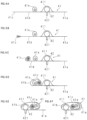
- FIG. 6 illustrates how the airbag cushion 41 is folded to be stowed in the stowage portion 40.
- FIG. 6 illustrates cross sections, as viewed from above, of the airbag cushion 41 being folded into a state illustrated in FIG. 5D .
- the inflator 42 is accommodated in the accommodating portion 411.
- the end of the third portion 41c is folded into the interior of the airbag cushion 41 in a direction toward the second portion 41b.
- the third portion 41c is folded into a roll shape.
- the direction in which the third portion 41c is folded is a direction in which an end portion of the third portion 41c is first folded clockwise and rolled so that the right-hand panel is on the outside, and as a result, the third portion 41c is roll-folded counterclockwise when viewed from above.
- this folding method is referred to as the "counterclockwise roll-folding.”
- the third portion 41c is further folded in, and is disposed between the roll-folded protruding portion 41e and the inflater 42.
- the second portion 41b, the protruding portion 41e, and the third portion 41c are folded back toward the first portion 41a.
- the third portion 41c and the protruding portion 41e are disposed on the opposite side, from the state illustrated in the drawing 6D, with respect to the inflator 42.
- the third portion 41c is disposed between the inflater 42 and the protruding portion 41e.
- the first portion 41a is folded leftward and rearward so as to be wound around and cover the protruding portion 41e and the third portion 41c.
- FIG. 7 is an explanatory diagram illustrating the process of deployment of the airbag cushion 41.
- FIG. 7 is a diagram of the passenger compartment 1 as viewed from above.
- FIG. 7A illustrates the state prior to the deployment.
- FIG. 7B illustrates the state immediately after the start of the deployment.
- gas enters the second portion 41b, and then the first portion 41e wound around the protruding portion 41e and the third portion 41a is deployed, by the deploying force, from the folded state while being inclined in the right direction of the passenger compartment 1.
- the third portion 41c is pushed out by the expansion of the second portion 41b, and is deployed on the side opposite to the inflator 42 with respect to the protruding portion 41e.
- the third portion 41c is roll-folded counterclockwise when viewed from above the passenger compartment 1, the third portion 41c is deployed as being inclined toward the assistant driver seat 3 by a force for deploying the third portion 41c from the folded state. Consequently, the airbag cushion 41 is transformed into a V-shaped state in plan view as illustrated in FIG. 7B .
- FIG. 7C shows a state in which the horizontal portion 41d is developed.
- FIG. 7D illustrates a state in which the airbag cushion 41 is completely deployed.
- the bottom end of the protruding portion 41e in the state illustrated in the drawing 7B is pushed upward and becomes the front end.
- the direction of the roll axis (the longitudinal axis) of the protruding portions 41e is changed from the upward-downward direction to the front-to-rear direction.
- the roll-folding of the protruding portion 41e has not been developed.
- the protruding portion 41e is developed upward to be in a state illustrated in FIG. 7D .
- FIG. 8 is a front view illustrating the airbag cushion 41 in a completely deployed state.
- the third portion 41c is in a state of riding on the assistant driver seat 3.
- the restraint position of the airbag cushion 41 is fixed, and, in addition, the reaction force from the seat of the assistant driver seat 3 can be utilized to alleviate the impact force of the collision that would otherwise be received by the occupant.
- the roll axis (that is, the longitudinal axis) of the roll-shaped protruding portion 41e changes its direction from the upward-downward direction to the front-to-rear direction. Due to this act, the airbag cushion 41 can be stably deployed in the front-to-rear direction so as to provide sufficient protection of the occupant.
- the protruding portion 41e and the third portion 41c are folded into a roll shape, but may be folded into a bellows shape.
Landscapes
- Engineering & Computer Science (AREA)
- Mechanical Engineering (AREA)
- Physics & Mathematics (AREA)
- Fluid Mechanics (AREA)
- Air Bags (AREA)
Abstract
A method of manufacturing an airbag device according to the present invention includes the steps of: folding, downwards from an upper side of a vehicle (100), a protruding portion (41e) into a roll shape; folding downwards an end of the roll-shaped protruding portion (41e) to come into contact with a side surface of the horizontal portion (41d) so that a longitudinal axis of the protruding portion (41e) is aligned in an upward-downward direction; folding a third portion (41c) into a roll shape or into a bellows shape; disposing the third portion (41c) having been folded into a roll shape between the protruding portion (41e) and the inflator (42); folding the second portion (41e), disposed on a side opposite to the first portion (41a) with respect to the accommodating portion (411), back toward the first portion (41a); and folding the first portion (41a) so as to wind around and cover the protruding portion (41e) and the third portion (41c).
Description
- The present invention relates to a method of manufacturing an airbag device and an airbag device.
- Vehicles in recent years have been equipped with airbag devices. An airbag device is a safety device which is actuated in case of an emergency such as a vehicle collision. When expanded and deployed by a gas pressure, the airbag device receives and thus protects the occupant. There are various types of airbag devices to be used depending on their installation site and on their application. For example, a front airbag is provided in a center of a steering wheel and is intended to protect a driver from a collision in a front-to-rear direction. Also provided are: curtain airbags, which are expanded and deployed along the side window from the wall near the ceiling to protect the occupants from a side collision or subsequent rollover; and side airbags, which are expanded and deployed from a side of a seat into the immediate side area of the occupant. A certain side airbag prevents the occupant seated in the driver seat from moving toward the assistant driver seat in the event of a side collision or the like (see Patent Literature 1).
- Patent Literature 1:
Japanese Unexamined Patent Application Publication No. 2010-115947 - The side air bag described in
Patent Literature 1 in the expanded and deployed state, however, may fail to provide sufficient protection of the occupant from the impact depending on the size of the vehicle, the installation place of the airbag, and the shape of the airbag. - The present invention has been made in view of such circumstances, and an object of the present invention is to provide a method of manufacturing an airbag device capable of expanding and deploying the airbag to provide sufficient protection of the occupant. Another object of the present invention is to provide such an airbag device.
- A method of manufacturing an airbag device according to the present invention is a method of manufacturing an airbag device (4) that comprises an airbag cushion (41) operable to expanded and deployed in a passenger compartment (1) of a vehicle (100) and thus to restrain an occupant seated on a seat (2, 3) from a side. The method includes the steps of: preparing the airbag cushion (41) including: a horizontal portion (41d) having an accommodating portion (411) for accommodating an inflater (42) for injecting a gas for expansion and deployment, the horizontal portion (41d) being operable to be deployed horizontally in the vehicle (100); and a protruding portion (41e) being operable to be deployed upward from a central portion of the horizontal portion (41d), wherein the horizontal portion (41d) of the airbag cushion (41) includes a first portion (41a) extending from the accommodating portion (411), a second portion (41b) extending horizontally in an opposite direction to the first portion (41b), and a third portion (41c) extending further from the second portion (41b); folding downwards from an upper side of the vehicle (100), the protruding portion (41e) into a roll shape or into a bellows shape; folding the protruding portion (41e) to come into contact with a side surface of the horizontal portion (41d) so that a longitudinal axis of the folded protruding portion (41e) is aligned in an upward-downward direction; folding the third portion (41c) into a roll shape or into a bellows shape; disposing the folded third portion (41c) between the protruding portion (41e) and the inflator (42); folding the second portion (41b), the protruding portion (41e), and the third portion (41c), all disposed on a side opposite to the first portion (41a) with respect to the accommodating portion (411) back toward the first portion (41a); and folding the first portion (41a) so as to wind around and cover the protruding portion (41e) and the third portion (41c).
- The method of manufacturing the airbag device according to the present invention further includes, before the step of folding the third portion (41c) into a roll shape or into a bellows shape, a step of folding an end of the third portion (41c) into the interior of the airbag cushion (41) in a direction toward the second portion (41b).
- In the method of manufacturing the airbag device according to the present invention, the airbag cushion (41) includes a bottom-surface gusset portion (41g) forming a surface facing the protruding portion (41e) when the airbag cushion (41) is in a deployed state, and the method further includes a step of folding the bottom-surface gusset portion (41g) so that an inner surface of the airbag cushion (41) comes into contact with the bottom-surface gusset portion (41g) and that an outer surface of the airbag cushion (41) is mountain-folded.
- An airbag device according to the present invention is an airbag device that includes an airbag cushion (41) operable to be expanded and deployed in a passenger compartment (1) of a vehicle (100) and thus to restrain an occupant seated on a seat (2, 3) from a side, wherein the airbag cushion (41) includes: a horizontal portion (41d) having an accommodating portion (411) for accommodating an inflator (42) for injecting a gas for expansion and deployment, the horizontal portion being operable to be deployed in a horizontal direction of the vehicle (100); and a protruding portion (41e) being operable to be deployed in an upward direction of the vehicle (100) from a central portion of the horizontal portion (41d), wherein the horizontal portion (41d) includes a first portion (41a) extending from the accommodating portion (411), a second portion (41b) extending horizontally in an opposite direction to the first portion (41a), and a third portion (41c) further extending from the second portion (41b), wherein the airbag device (4) includes: a configuration in which the protruding portion (41e) is folded, downwards from an upper side of the vehicle (100), into a roll shape or into a bellows shape; a configuration in which the roll-shaped protruding portion (41e) is folded to come into contact with a side surface of the horizontal portion (41d) so that a longitudinal axis of the folded protruding portion (41e) is aligned in an upward-downward direction; a configuration in which the third portion (41c) is folded into a roll shape or into a bellows shape; a configuration in which the folded third portion (41c) is disposed between the protruding portion (41e) and the inflator (42); a configuration in which the second portion (41b), the protruding portion (41e), and the third portion (41c), all disposed on a side opposite to the first portion (41b) with respect to the accommodating portion (411), are folded back toward the first portion (41a); and a configuration in which the first portion (41a) is folded so as to be wound around and cover the protruding portion (41e) and the third portion (41c).
- The method of manufacturing an airbag device according to an embodiment of the present invention provides a method of manufacturing an airbag device expanding and deploying the airbag cushion so as to be able to provide sufficient protection of the occupant.
-
-
FIG. 1 is a perspective view schematically illustrating the inside of a vehicle equipped with a side airbag device. -
FIG. 2 is a plan view schematically illustrating the inside of the vehicle equipped with the side airbag device. -
FIG. 3 is a cross section view of the side airbag device taken along line III-III inFIG. 1 . -
FIG. 4 is a perspective view illustrating an example airbag cushion. -
FIG. 5 is an explanatory diagram illustrating a method of folding the airbag cushion. -
FIG. 6 is an explanatory diagram illustrating a method of folding the airbag cushion. -
FIG. 7 is an explanatory diagram illustrating the process of deploying the airbag cushion. -
FIG. 8 is a front view illustrating the airbag cushion in a completely deployed state. - An embodiment of the present invention is described below based on the drawings. The "upward" direction, the "downward" direction, and the "upward-downward (vertical)" direction referred to in the descriptions below indicate a direction on a line connecting the center of the roof of the vehicle to the center of the floor of the vehicle, where the direction toward the roof is the "upward" direction and the direction toward the floor is the "downward" direction. The "forward" direction, the "backward (rearward)" direction and "front-to-rear" directions of a vehicle indicate directions in which the vehicle is traveling, where the direction in which the vehicle is progressing is referred to as the "forward" direction, and the direction in which the vehicle is retrogressing is referred to as the "backward (rearward)" direction. Furthermore, the width direction of the vehicle is the direction in which the seats are usually arranged side by side with each other, and is the direction perpendicular to the above-mentioned "front-to-rear" direction. The width direction includes the "rightward direction," which is the direction towards the side of the
driver seat 2 and the "leftward direction," which is the direction towards the side of theassistant driver seat 3. A direction along a plane orthogonal to the upward-downward (vertical) direction (a plane extending both in the front-to-rear direction and in the width direction) is defined as a horizontal direction. -
FIG. 1 is a perspective view schematically illustrating the inside of avehicle 100 equipped with aside airbag device 4.FIG. 2 is a plan view schematically illustrating the inside of thevehicle 100 equipped with theside airbag device 4.FIGS. 1 and2 illustrate a driver seat (seat) 2 and an assistant driver seat (seat) 3 installed on afloor 10 of apassenger compartment 1, as well as aseatbelt 5. Thedriver seat 2 includes aseat portion 21 and abackrest 22 that rises upward from the rear side of theseat portion 21. Thebackrest 22 includes acushioning material 221 and askin 222 covering a surface of the cushioning material 221 (seeFIG. 3 ). Thecushioning material 221 is made of polyurethane resin, for example, and theskin 222 is made of woven fabric, synthetic leather, natural leather, or the like, for example. - As illustrated in
FIG. 2 , in thedriver seat 2 installed in thepassenger compartment 1 of thevehicle 100, the side airbag device (airbag device) 4 is disposed inside thebackrest 22 of thedriver seat 2 on the side near theassistant driver seat 3. As illustrated inFIG. 1 , theside airbag device 4 has a rectangular parallelepiped shape. Theside airbag device 4 may be disposed inside the backrest of theassistant driver seat 3 on the side near thedriver seat 2. -
FIG. 3 is a cross section view of theside airbag device 4 taken along line III-III inFIG. 1 . The upward direction and the downward direction in this figure correspond, respectively, the forward direction and the backward (rearward) direction of thevehicle 100. Theside airbag device 4 includes anairbag cushion 41 and aninflator 42, which are stowed in thestowage portion 40. - The
airbag cushion 41 is, for example, a bag-shaped body made of cloth reinforced by the weaving in of high-strength fibers such as a nylon fiber or the like. The airbag cushion folded in a roll shape is stowed inside thestowage portion 40. The shape and folding method of theairbag cushion 41 will be described later. Theinflator 42 is secured to theskeletal frame 23 of thebackrest 22 by thestud bolts 421 with the base plate of the stowage portion held in between. Theinflator 42 has its gas for expansion and deployment stored inside theairbag cushion 41. - The
stowage portion 40 is a box-shaped body having one open surface, and is fixed to theskeleton frame 23 of thebackrest 22 bystud bolts 43 and the above-describedstud bolts 421. The opening of thestowage portion 40 is oriented towards theassistant driver seat 3, and is covered by acover plate 44 that is flush with the side surface of thedriver seat 2. Thecover plate 44 is a resin plate having a lower strength than thestowage portion 40. Acleavage groove 45 is formed in the front portion of the outer surface of thecover plate 44 over the entire length in the upward-downward direction. Theairbag cushion 41 is expanded explosively by the action of the injected gas of theinflator 42 at the time of a collision of thevehicle 100, ruptures thecover plate 44 at the position of thecleavage groove 45 to break through theskin 222, and is deployed sideways. Although thecleavage groove 45 illustrated inFIG. 3 is formed on the outer surface of thecover plate 44, it may be formed on the inner surface of thecover plate 44. -
FIG. 4 is a perspective view illustrating an example of theairbag cushion 41.FIG. 4 illustrates theairbag cushion 41 in an expanded state. Directions mentioned inFIG. 4 indicate the directions described above with respect to thevehicle 100. Theairbag cushion 41 having a shape with a raised middle section includes: ahorizontal portion 41d that extends and is deployed horizontally (that is, in the front-to-rear direction and in the width direction) in thevehicle 100; and a protrudingportion 41e that is deployed upward in thevehicle 100 from a central portion, in the front-to-rear direction, of thehorizontal portion 41e. Theairbag cushion 41 is formed by joining two panels each having a shape with a raised middle section in a plan view. The two panels are joined by means of an upper-surface gusset portion 41f and a bottom-surface gusset portion 41g interposed in between to give a greater thickness in the width direction. The two panels form side surfaces of thehorizontal portion 41d and of the protrudingportion 41e. Anaccommodating portion 411 that accommodates the cylinder-type (tube-type)inflator 42 is provided inside theairbag cushion 41. Theaccommodating portion 411 is provided withinsertion holes stud bolts 421 of the inflator 42 are inserted. The inflator 42 is actuated in the event of an emergency, such as a collision of avehicle 100 and the like, and injects gas into theairbag cushion 41. Theairbag cushion 41 is expanded explosively by the action of the injected gas of theinflator 42. The pressure to expanding theairbag cushion 41 acts on thecover plate 44 with the bottom plate of thestowage portion 40 serving as a support. Theairbag cushion 41 ruptures thecleavage groove 45, and is expanded and deployed to the outside of thestowage portion 40. Hereinafter, the act of expansion and deployment is also simply referred to as the act of deployment. - In the following description, the
horizontal portion 41d of theairbag cushion 41 is assumed to be composed of three conceptually different portions. The front portion is referred to as afirst portion 41a, a portion located immediately behind (rearward from) theaccommodating portion 411 is referred to as asecond portion 41b, and a portion located further rearward from thesecond portion 41b is referred to as athird portion 41c. Thefirst portion 41a is a portion extending from one end portion of theairbag cushion 41 in the front-rear direction to the vicinity of theaccommodating portion 411. Thesecond portion 41b is a portion extending by a predetermined length in a direction opposite to thefirst portion 41a in the front-to-rear direction when viewed from theaccommodating portion 411. Thethird portion 41c is a portion further extending from thesecond portion 41a and disposed on the opposite side of thefirst portion 41b with respect to theaccommodating portion 411. Thesecond portion 41b is mainly provided at a position corresponding to a portion of a space between the two adjacent seats (that is, thedriver seat 2 and the assistant driver seat 3). Thefirst portion 41a, thesecond portion 41b, and thethird portion 41c are conceptual divisions. Neither the boundary between thefirst portion 41a and thesecond portion 41b nor the boundary between thesecond portion 41b and thethird portion 41c is not precise in any way. In addition, the position of theaccommodating portion 411 illustrated inFIG. 4 is the boundary between thefirst portion 41a and thesecond portion 41b, but it is not limited thereto. The position of theaccommodating portion 411 may be moved forward or rearward from the position illustrated inFIG. 4 . To put it differently, when the boundary dividing thefirst portion 41a and thesecond portion 41b is set to the vicinity of the front end portion of the raised middle section in the front-rear direction as illustrated inFIG. 4 regardless of the position of theaccommodating portion 411, theaccommodating portion 411 may be located either in thefirst portion 41a or in thesecond portion 41b. -
FIG. 5 to FIG. 6 are explanatory diagrams illustrating a method of expansion and deployment of theairbag cushion 41.FIG. 5 illustrates a method of folding the protrudingportion 41e. It should be noted thatFIG. 5 is a diagram depicting theairbag cushion 41, as viewed from the left-hand side. As illustrated in theFIGS. 5A and 5B , the protrudingportion 41e is flattened in the front-rear direction to be transformed into a sheet-like shape having sides in the upward-downward direction and the width direction. Thereafter, as illustrated inFIG. 5C , the protrudingportion 41e, now in a sheet-like state, is folded into a roll shape downwards from its upper side with its upper end first folded toward thefirst portion 41a side using the width direction as a roll axis direction. In this case, the upper end of the protrudingportion 41e may be first folded forward to form a roll shape, but alternatively, the upper end may also be first folded backward to form a roll shape. The protrudingportion 41e folded into a roll shape as illustrated inFIG. 5C is folded together with the upper-surface gusset portion 41f so that the roll axis (that is, the longitudinal axis) is aligned in the upward-downward direction and the protrudingportion 41e comes into contact with the left-hand surface (side surface) of thehorizontal portion 41d as illustrated inFIG. 5D . When theairbag cushion 41 is transformed into the state illustrated inFIG. 5D , the bottom-surface gusset portion 41g is folded such that the inner surface of theairbag cushion 41 comes into contact with the bottom-surface gusset portion 41g and the outer surface of the bottom-surface gusset portion 41g is mountain-folded. -
FIG. 6 illustrates how theairbag cushion 41 is folded to be stowed in thestowage portion 40.FIG. 6 illustrates cross sections, as viewed from above, of theairbag cushion 41 being folded into a state illustrated inFIG. 5D . As illustrated inFIG. 6A , theinflator 42 is accommodated in theaccommodating portion 411. As illustrated inFIG. 6B , the end of thethird portion 41c is folded into the interior of theairbag cushion 41 in a direction toward thesecond portion 41b. As illustrated inFIG. 6C , thethird portion 41c is folded into a roll shape. The direction in which thethird portion 41c is folded is a direction in which an end portion of thethird portion 41c is first folded clockwise and rolled so that the right-hand panel is on the outside, and as a result, thethird portion 41c is roll-folded counterclockwise when viewed from above. Hereinafter, this folding method is referred to as the "counterclockwise roll-folding." As illustrated inFIG. 6D , thethird portion 41c is further folded in, and is disposed between the roll-foldedprotruding portion 41e and theinflater 42. As illustrated inFIG. 6E , thesecond portion 41b, the protrudingportion 41e, and thethird portion 41c are folded back toward thefirst portion 41a. Accordingly, thethird portion 41c and the protrudingportion 41e are disposed on the opposite side, from the state illustrated in the drawing 6D, with respect to theinflator 42. Thethird portion 41c is disposed between theinflater 42 and the protrudingportion 41e. As illustrated inFIG. 6F , thefirst portion 41a is folded leftward and rearward so as to be wound around and cover the protrudingportion 41e and thethird portion 41c. -
FIG. 7 is an explanatory diagram illustrating the process of deployment of theairbag cushion 41.FIG. 7 is a diagram of thepassenger compartment 1 as viewed from above.FIG. 7A illustrates the state prior to the deployment.FIG. 7B illustrates the state immediately after the start of the deployment. After the start of the deployment, gas enters thesecond portion 41b, and then thefirst portion 41e wound around the protrudingportion 41e and thethird portion 41a is deployed, by the deploying force, from the folded state while being inclined in the right direction of thepassenger compartment 1. In addition, thethird portion 41c is pushed out by the expansion of thesecond portion 41b, and is deployed on the side opposite to the inflator 42 with respect to the protrudingportion 41e. During this process, since thethird portion 41c is roll-folded counterclockwise when viewed from above thepassenger compartment 1, thethird portion 41c is deployed as being inclined toward theassistant driver seat 3 by a force for deploying thethird portion 41c from the folded state. Consequently, theairbag cushion 41 is transformed into a V-shaped state in plan view as illustrated inFIG. 7B . -
FIG. 7C shows a state in which thehorizontal portion 41d is developed.FIG. 7D illustrates a state in which theairbag cushion 41 is completely deployed. Once thehorizontal portion 41d of theairbag cushion 41 is deployed, the bottom end of the protrudingportion 41e in the state illustrated in the drawing 7B is pushed upward and becomes the front end. To put it differently, the direction of the roll axis (the longitudinal axis) of the protrudingportions 41e is changed from the upward-downward direction to the front-to-rear direction. In the state illustrated inFIG. 7C , the roll-folding of the protrudingportion 41e has not been developed. Thereafter, the protrudingportion 41e is developed upward to be in a state illustrated inFIG. 7D . -
FIG. 8 is a front view illustrating theairbag cushion 41 in a completely deployed state. As illustrated inFIGS.7D and8 , in theairbag cushion 41 in the deployed state, thethird portion 41c is in a state of riding on theassistant driver seat 3. Hence, it is possible to prevent the occupant seated in thedriver seat 2 from moving toward theassistant driver seat 3. The restraint position of theairbag cushion 41 is fixed, and, in addition, the reaction force from the seat of theassistant driver seat 3 can be utilized to alleviate the impact force of the collision that would otherwise be received by the occupant. - According to the above-described configuration, during the deployment of the roll-shaped protruding
portion 41e that has been folded with its two ends facing downwards, the roll axis (that is, the longitudinal axis) of the roll-shaped protrudingportion 41e changes its direction from the upward-downward direction to the front-to-rear direction. Due to this act, theairbag cushion 41 can be stably deployed in the front-to-rear direction so as to provide sufficient protection of the occupant. In the present invention, the protrudingportion 41e and thethird portion 41c are folded into a roll shape, but may be folded into a bellows shape. - When a reference code is noted in a claim, the reference code is merely provided as a reference in correspondence with the reference code described in the embodiment in order to facilitate understanding of the claim. The scope of claims is not limited by the reference code.
- The embodiments presently disclosed are to be considered as examples for all points, and are not restrictive. The technical features described in the examples can be combined with each other, and the scope of the invention is intended to include all changes within the scope of the claims and a scope equal to the claims. Furthermore, the independent and dependent claims set forth in the claims can be combined with each other in any and all combinations, regardless of the form of reference. Furthermore, the claims are in a format in which a claim refers to two or more other claims (multiple claim format), but the present invention is not limited to this format. A multiple claim (multi-multi claim) may be written using a format that cites at least one multiple claim.
-
- 100. Vehicle
- 1. Passenger compartment
- 2. Driver seat (Seat)
- 3. Assistant driver seat (Seat)
- 4. Side airbag device (Airbag device)
- 41. Airbag cushion
- 41a. First portion
- 41b. Second portion
- 41c. Third portion
- 41d. Horizontal portion
- 41e. Protruding portion
- 41f. Upper-surface gusset portion
- 41g. Bottom-surface gusset portion
- 411. Accommodating portion
- 42. Inflator
Claims (4)
- A method of manufacturing an airbag device (4) that comprises an airbag cushion (41) operable to expanded and deployed in a passenger compartment (1) of a vehicle (100) and thus to restrain an occupant seated on a seat (2, 3) from a side, the method comprising the step of:preparing the airbag cushion (41) including: a horizontal portion (41d) having an accommodating portion (411) for accommodating an inflater (42) for injecting a gas for expansion and deployment, the horizontal portion (41d) being operable to be deployed horizontally in the vehicle (100); and a protruding portion (41e) being operable to be deployed upward from a central portion of the horizontal portion (41d), wherein the horizontal portion (41d) of the airbag cushion (41) includes a first portion (41a) extending from the accommodating portion (411), a second portion (41b) extending horizontally in an opposite direction to the first portion (41b), and a third portion (41c) extending further from the second portion (41b);folding downwards from an upper side of the vehicle (100), the protruding portion (41e) into a roll shape or into a bellows shape;folding the protruding portion (41e) to come into contact with a side surface of the horizontal portion (41d) so that a longitudinal axis of the folded protruding portion (41e) is aligned in an upward-downward direction;folding the third portion (41c) into a roll shape or into a bellows shape;disposing the folded third portion (41c) between the protruding portion (41e) and the inflator (42);folding the second portion (41b), the protruding portion (41e), and the third portion (41c), all disposed on a side opposite to the first portion (41a) with respect to the accommodating portion (411) back toward the first portion (41a); andfolding the first portion (41a) so as to wind around and cover the protruding portion (41e) and the third portion (41c).
- The method of manufacturing an airbag device according to Claim 1 further comprising: before the step of folding the third portion (41c) into a roll shape or into a bellows shape,
a step of folding an end of the third portion (41c) into the interior of the airbag cushion (41) in a direction toward the second portion (41b). - The method of manufacturing an airbag device (4) according to claim 1 or 2, wherein the airbag cushion (41) includes a bottom-surface gusset portion (41g) forming a surface facing the protruding portion (41e) when the airbag cushion (41) is in a deployed state, and
wherein the method further comprises a step of folding the bottom-surface gusset portion (41g) so that an inner surface of the airbag cushion (41) comes into contact with the bottom-surface gusset portion (41g) and that an outer surface of the airbag cushion (41) is mountain-folded. - An airbag device (4) comprising an airbag cushion (41) operable to be expanded and deployed in a passenger compartment (1) of a vehicle (100) and thus to restrain an occupant seated on a seat (2, 3) from a side,wherein the airbag cushion (41) includes: a horizontal portion (41d) having an accommodating portion (411) for accommodating an inflator (42) for injecting a gas for expansion and deployment, the horizontal portion being operable to be deployed in a horizontal direction of the vehicle (100); and a protruding portion (41e) being operable to be deployed in an upward direction of the vehicle (100) from a central portion of the horizontal portion (41d),wherein the horizontal portion (41d) includes a first portion (41a) extending from the accommodating portion (411), a second portion (41b) extending horizontally in an opposite direction to the first portion (41a), and a third portion (41c) further extending from the second portion (41b),wherein the airbag device (4) includes: a configuration in which the protruding portion (41e) is folded, downwards from an upper side of the vehicle (100), into a roll shape or into a bellows shape;a configuration in which the roll-shaped protruding portion (41e) is folded to come into contact with a side surface of the horizontal portion (41d) so that a longitudinal axis of the folded protruding portion (41e) is aligned in an upward-downward direction;a configuration in which the third portion (41c) is folded into a roll shape or into a bellows shape;a configuration in which the folded third portion (41c) is disposed between the protruding portion (41e) and the inflator (42);a configuration in which the second portion (41b), the protruding portion (41e), and the third portion (41c), all disposed on a side opposite to the first portion (41b) with respect to the accommodating portion (411), are folded back toward the first portion (41a); anda configuration in which the first portion (41a) is folded so as to be wound around and cover the protruding portion (41e) and the third portion (41c).
Applications Claiming Priority (2)
| Application Number | Priority Date | Filing Date | Title |
|---|---|---|---|
| JP2022133343 | 2022-08-24 | ||
| PCT/JP2023/026841 WO2024042943A1 (en) | 2022-08-24 | 2023-07-21 | Air bag device manufacturing method, and air bag device |
Publications (1)
| Publication Number | Publication Date |
|---|---|
| EP4556320A1 true EP4556320A1 (en) | 2025-05-21 |
Family
ID=90013228
Family Applications (1)
| Application Number | Title | Priority Date | Filing Date |
|---|---|---|---|
| EP23857059.2A Pending EP4556320A1 (en) | 2022-08-24 | 2023-07-21 | Air bag device manufacturing method, and air bag device |
Country Status (5)
| Country | Link |
|---|---|
| EP (1) | EP4556320A1 (en) |
| JP (1) | JP7742943B2 (en) |
| KR (1) | KR20250051675A (en) |
| CN (1) | CN119654259A (en) |
| WO (1) | WO2024042943A1 (en) |
Family Cites Families (6)
| Publication number | Priority date | Publication date | Assignee | Title |
|---|---|---|---|---|
| JP2962224B2 (en) * | 1996-04-08 | 1999-10-12 | 三菱自動車工業株式会社 | Airbag for side impact |
| JP2010115947A (en) | 2008-11-11 | 2010-05-27 | Toyota Motor Corp | Airbag device between vehicle seats |
| KR101090051B1 (en) | 2009-04-21 | 2011-12-07 | 우리산업 주식회사 | Structure of current sensor and its manufacturing method |
| JP7406367B2 (en) * | 2019-02-12 | 2023-12-27 | オートリブ ディベロップメント エービー | Airbag device, method for manufacturing an airbag device, and method for deploying an airbag device |
| US10926735B2 (en) * | 2019-04-02 | 2021-02-23 | Ford Global Technologies, Llc | Vehicle seat side airbag |
| JP7606350B2 (en) * | 2020-03-13 | 2024-12-25 | オートリブ ディベロップメント エービー | Method for manufacturing an airbag device and an airbag device. |
-
2023
- 2023-07-21 KR KR1020257005896A patent/KR20250051675A/en active Pending
- 2023-07-21 CN CN202380057842.8A patent/CN119654259A/en active Pending
- 2023-07-21 JP JP2024542663A patent/JP7742943B2/en active Active
- 2023-07-21 EP EP23857059.2A patent/EP4556320A1/en active Pending
- 2023-07-21 WO PCT/JP2023/026841 patent/WO2024042943A1/en not_active Ceased
Also Published As
| Publication number | Publication date |
|---|---|
| WO2024042943A1 (en) | 2024-02-29 |
| JPWO2024042943A1 (en) | 2024-02-29 |
| JP7742943B2 (en) | 2025-09-22 |
| CN119654259A (en) | 2025-03-18 |
| KR20250051675A (en) | 2025-04-17 |
Similar Documents
| Publication | Publication Date | Title |
|---|---|---|
| EP3696030B1 (en) | Airbag device, method for manufacturing airbag device, and method for deploying airbag device | |
| EP3357764B1 (en) | Vehicle seat with side airbag device | |
| US11833990B2 (en) | Side airbag device, vehicle seat provided with same, and method for manufacturing side airbag device | |
| EP3741629B1 (en) | Airbag device | |
| US11267433B2 (en) | Side airbag device and vehicle seat provided with same | |
| CN112009418A (en) | Side airbag device | |
| KR102460804B1 (en) | Airbag device manufacturing method and airbag device | |
| JP7406367B2 (en) | Airbag device, method for manufacturing an airbag device, and method for deploying an airbag device | |
| JP5130856B2 (en) | Rear seat airbag device | |
| CN113386700B (en) | Method for manufacturing airbag device and airbag device | |
| JP7551404B2 (en) | Airbag device | |
| EP4556320A1 (en) | Air bag device manufacturing method, and air bag device | |
| JP2018114838A (en) | Airbag | |
| JP7642590B2 (en) | Airbag device manufacturing method and airbag device | |
| WO2024024473A1 (en) | Vehicle side airbag device and airbag cushion production method | |
| EP4005880B1 (en) | Side airbag device and method of manufacturing a side airbag device | |
| CN112677921A (en) | Airbag device | |
| WO2024018877A1 (en) | Airbag device and method for manufacturing airbag device |
Legal Events
| Date | Code | Title | Description |
|---|---|---|---|
| STAA | Information on the status of an ep patent application or granted ep patent |
Free format text: STATUS: THE INTERNATIONAL PUBLICATION HAS BEEN MADE |
|
| PUAI | Public reference made under article 153(3) epc to a published international application that has entered the european phase |
Free format text: ORIGINAL CODE: 0009012 |
|
| STAA | Information on the status of an ep patent application or granted ep patent |
Free format text: STATUS: REQUEST FOR EXAMINATION WAS MADE |
|
| 17P | Request for examination filed |
Effective date: 20250212 |
|
| AK | Designated contracting states |
Kind code of ref document: A1 Designated state(s): AL AT BE BG CH CY CZ DE DK EE ES FI FR GB GR HR HU IE IS IT LI LT LU LV MC ME MK MT NL NO PL PT RO RS SE SI SK SM TR |
|
| DAV | Request for validation of the european patent (deleted) | ||
| DAX | Request for extension of the european patent (deleted) |