EP4556267A1 - Thermal management system and vehicle - Google Patents
Thermal management system and vehicle Download PDFInfo
- Publication number
- EP4556267A1 EP4556267A1 EP23896121.3A EP23896121A EP4556267A1 EP 4556267 A1 EP4556267 A1 EP 4556267A1 EP 23896121 A EP23896121 A EP 23896121A EP 4556267 A1 EP4556267 A1 EP 4556267A1
- Authority
- EP
- European Patent Office
- Prior art keywords
- air
- circuit
- air inlet
- heat exchanger
- air outlet
- Prior art date
- Legal status (The legal status is an assumption and is not a legal conclusion. Google has not performed a legal analysis and makes no representation as to the accuracy of the status listed.)
- Pending
Links
Images

Classifications
-
- B—PERFORMING OPERATIONS; TRANSPORTING
- B60—VEHICLES IN GENERAL
- B60H—ARRANGEMENTS OF HEATING, COOLING, VENTILATING OR OTHER AIR-TREATING DEVICES SPECIALLY ADAPTED FOR PASSENGER OR GOODS SPACES OF VEHICLES
- B60H1/00—Heating, cooling or ventilating devices
- B60H1/32—Cooling devices
- B60H1/3204—Cooling devices using compression
- B60H1/3228—Cooling devices using compression characterised by refrigerant circuit configurations
-
- B—PERFORMING OPERATIONS; TRANSPORTING
- B60—VEHICLES IN GENERAL
- B60H—ARRANGEMENTS OF HEATING, COOLING, VENTILATING OR OTHER AIR-TREATING DEVICES SPECIALLY ADAPTED FOR PASSENGER OR GOODS SPACES OF VEHICLES
- B60H1/00—Heating, cooling or ventilating devices
- B60H1/00007—Combined heating, ventilating, or cooling devices
- B60H1/00021—Air flow details of HVAC devices
- B60H1/00035—Air flow details of HVAC devices for sending an air stream of uniform temperature into the passenger compartment
- B60H1/00057—Air flow details of HVAC devices for sending an air stream of uniform temperature into the passenger compartment the air being heated and cooled simultaneously, e.g. using parallel heat exchangers
-
- B—PERFORMING OPERATIONS; TRANSPORTING
- B60—VEHICLES IN GENERAL
- B60H—ARRANGEMENTS OF HEATING, COOLING, VENTILATING OR OTHER AIR-TREATING DEVICES SPECIALLY ADAPTED FOR PASSENGER OR GOODS SPACES OF VEHICLES
- B60H1/00—Heating, cooling or ventilating devices
- B60H1/00271—HVAC devices specially adapted for particular vehicle parts or components and being connected to the vehicle HVAC unit
- B60H1/00278—HVAC devices specially adapted for particular vehicle parts or components and being connected to the vehicle HVAC unit for the battery
-
- B—PERFORMING OPERATIONS; TRANSPORTING
- B60—VEHICLES IN GENERAL
- B60H—ARRANGEMENTS OF HEATING, COOLING, VENTILATING OR OTHER AIR-TREATING DEVICES SPECIALLY ADAPTED FOR PASSENGER OR GOODS SPACES OF VEHICLES
- B60H1/00—Heating, cooling or ventilating devices
- B60H1/00642—Control systems or circuits; Control members or indication devices for heating, cooling or ventilating devices
- B60H1/00814—Control systems or circuits characterised by their output, for controlling particular components of the heating, cooling or ventilating installation
- B60H1/00878—Control systems or circuits characterised by their output, for controlling particular components of the heating, cooling or ventilating installation the components being temperature regulating devices
- B60H1/00899—Controlling the flow of liquid in a heat pump system
-
- B—PERFORMING OPERATIONS; TRANSPORTING
- B60—VEHICLES IN GENERAL
- B60H—ARRANGEMENTS OF HEATING, COOLING, VENTILATING OR OTHER AIR-TREATING DEVICES SPECIALLY ADAPTED FOR PASSENGER OR GOODS SPACES OF VEHICLES
- B60H1/00—Heating, cooling or ventilating devices
- B60H1/02—Heating, cooling or ventilating devices the heat being derived from the propulsion plant
- B60H1/04—Heating, cooling or ventilating devices the heat being derived from the propulsion plant from cooling liquid of the plant
-
- B—PERFORMING OPERATIONS; TRANSPORTING
- B60—VEHICLES IN GENERAL
- B60H—ARRANGEMENTS OF HEATING, COOLING, VENTILATING OR OTHER AIR-TREATING DEVICES SPECIALLY ADAPTED FOR PASSENGER OR GOODS SPACES OF VEHICLES
- B60H1/00—Heating, cooling or ventilating devices
- B60H1/32—Cooling devices
- B60H1/3204—Cooling devices using compression
- B60H1/323—Cooling devices using compression characterised by comprising auxiliary or multiple systems, e.g. plurality of evaporators, or by involving auxiliary cooling devices
-
- H—ELECTRICITY
- H01—ELECTRIC ELEMENTS
- H01M—PROCESSES OR MEANS, e.g. BATTERIES, FOR THE DIRECT CONVERSION OF CHEMICAL ENERGY INTO ELECTRICAL ENERGY
- H01M10/00—Secondary cells; Manufacture thereof
- H01M10/60—Heating or cooling; Temperature control
- H01M10/62—Heating or cooling; Temperature control specially adapted for specific applications
- H01M10/625—Vehicles
-
- H—ELECTRICITY
- H01—ELECTRIC ELEMENTS
- H01M—PROCESSES OR MEANS, e.g. BATTERIES, FOR THE DIRECT CONVERSION OF CHEMICAL ENERGY INTO ELECTRICAL ENERGY
- H01M10/00—Secondary cells; Manufacture thereof
- H01M10/60—Heating or cooling; Temperature control
- H01M10/65—Means for temperature control structurally associated with the cells
- H01M10/656—Means for temperature control structurally associated with the cells characterised by the type of heat-exchange fluid
- H01M10/6567—Liquids
- H01M10/6568—Liquids characterised by flow circuits, e.g. loops, located externally to the cells or cell casings
-
- H—ELECTRICITY
- H01—ELECTRIC ELEMENTS
- H01M—PROCESSES OR MEANS, e.g. BATTERIES, FOR THE DIRECT CONVERSION OF CHEMICAL ENERGY INTO ELECTRICAL ENERGY
- H01M10/00—Secondary cells; Manufacture thereof
- H01M10/60—Heating or cooling; Temperature control
- H01M10/66—Heat-exchange relationships between the cells and other systems, e.g. central heating systems or fuel cells
- H01M10/663—Heat-exchange relationships between the cells and other systems, e.g. central heating systems or fuel cells the system being an air-conditioner or an engine
-
- B—PERFORMING OPERATIONS; TRANSPORTING
- B60—VEHICLES IN GENERAL
- B60H—ARRANGEMENTS OF HEATING, COOLING, VENTILATING OR OTHER AIR-TREATING DEVICES SPECIALLY ADAPTED FOR PASSENGER OR GOODS SPACES OF VEHICLES
- B60H1/00—Heating, cooling or ventilating devices
- B60H1/00007—Combined heating, ventilating, or cooling devices
- B60H1/00021—Air flow details of HVAC devices
- B60H2001/0015—Temperature regulation
- B60H2001/00178—Temperature regulation comprising an air passage from the HVAC box to the exterior of the cabin
-
- B—PERFORMING OPERATIONS; TRANSPORTING
- B60—VEHICLES IN GENERAL
- B60H—ARRANGEMENTS OF HEATING, COOLING, VENTILATING OR OTHER AIR-TREATING DEVICES SPECIALLY ADAPTED FOR PASSENGER OR GOODS SPACES OF VEHICLES
- B60H1/00—Heating, cooling or ventilating devices
- B60H1/00271—HVAC devices specially adapted for particular vehicle parts or components and being connected to the vehicle HVAC unit
- B60H2001/00307—Component temperature regulation using a liquid flow
-
- H—ELECTRICITY
- H01—ELECTRIC ELEMENTS
- H01M—PROCESSES OR MEANS, e.g. BATTERIES, FOR THE DIRECT CONVERSION OF CHEMICAL ENERGY INTO ELECTRICAL ENERGY
- H01M2220/00—Batteries for particular applications
- H01M2220/20—Batteries in motive systems, e.g. vehicle, ship, plane
-
- Y—GENERAL TAGGING OF NEW TECHNOLOGICAL DEVELOPMENTS; GENERAL TAGGING OF CROSS-SECTIONAL TECHNOLOGIES SPANNING OVER SEVERAL SECTIONS OF THE IPC; TECHNICAL SUBJECTS COVERED BY FORMER USPC CROSS-REFERENCE ART COLLECTIONS [XRACs] AND DIGESTS
- Y02—TECHNOLOGIES OR APPLICATIONS FOR MITIGATION OR ADAPTATION AGAINST CLIMATE CHANGE
- Y02T—CLIMATE CHANGE MITIGATION TECHNOLOGIES RELATED TO TRANSPORTATION
- Y02T10/00—Road transport of goods or passengers
- Y02T10/60—Other road transportation technologies with climate change mitigation effect
- Y02T10/70—Energy storage systems for electromobility, e.g. batteries
Definitions
- the present application relates to the technical field of vehicles, and in particular to a thermal management system and a vehicle.
- the thermal management system using the heat pump system and the PTC heater still has some defects.
- the present heat pump system is complicated to switch between cooling and heating for passenger compartment, which needs the compressor to stop working, the functional needs can only be achieved by adjusting the on/off valve and different electronic expansion valves, and the PTC heater is also required to provide supplement heat.
- the heating efficiency of the PTC heater is lower than 1, the start of the PTC heater will increase the energy consumption of the whole vehicle and thus affect the cruising range
- the main purpose of the present application is to provide a thermal management system, aiming to simplify the thermal management system and reduce the energy consumption of the whole vehicle.
- the thermal management system provided in the present application includes:
- the thermal management system further includes: an air conditioner main unit including a first heat exchange air duct, a second heat exchange air duct and a circulating air duct;
- the first heat exchange air duct is provided with a condenser, a first air inlet end and a first air outlet end, the first air inlet end includes a first air inlet communicated with a circulating air inlet and a second air inlet communicated with an outside of a vehicle, and the first air outlet end is respectively communicated with a first air outlet communicated with an inside of the vehicle and a second air outlet communicated with the outside of the vehicle;
- the refrigerant circuit includes a first circuit and a second circuit
- the first circuit is a closed circuit formed by the compressor, the second heat exchanger, the condenser, the first expansion valve, and the first heat exchanger connected in series in sequence
- the second circuit is a closed circuit formed by the first evaporator, the second expansion valve, the third expansion valve, and the second evaporator connected in series in sequence
- a flow channel between the second evaporator and the first evaporator is connected in series with a flow channel between the compressor and the first heat exchanger
- a flow channel between the second expansion valve and the third expansion valve is connected in series with a flow channel between the condenser and the first expansion valve.
- the thermal management system has a first heating state
- the first air inlet, the second air inlet, the third air inlet, the fourth air outlet and the circulating air duct are all communicated, and the in-vehicle circulating air inlet, the first air outlet, the second air outlet, the third air outlet and the fourth air inlet are all blocked, so that an air outside the vehicle is configured to enter the first heat exchange air duct for heat exchange and pass through the first circulating air duct; and a part of the air is configured to enter the first air inlet to continue circulation, and another part of the air is configured to flow into the second heat exchange air duct through the third air inlet for heat exchange and is discharged out of the vehicle.
- the thermal management system has a second heating state; and in the second heating state, the water circuit is connected in parallel with the refrigerant circuit through the first heat exchanger and the second heat exchanger respectively, and the water circuit is configured as a closed circuit formed by the first water pump, the drive assembly, the first four-way valve, the second heat exchanger, the second four-way valve, the second water pump, the battery assembly, the first four-way valve, the first heat exchanger, the second four-way valve, and the three-way valve connected in series in sequence.
- the in-vehicle circulating air inlet, the first air inlet, the second air inlet, the fourth air inlet, the first air outlet and the fourth air outlet are all communicated, and the third air inlet, the second air outlet, the third air outlet and the circulating air duct are all blocked, so that the air after heat exchange through the first heat exchange air duct is discharged into the vehicle and is circulated to the first heat exchange air duct together with an air inside the vehicle.
- the drive assembly includes a first drive motor, a first control assembly, a second drive motor and a second control assembly
- the water circuit includes a first branch and a second branch provided in parallel
- the first drive motor and the first control assembly are connected in series to the first branch
- the second drive motor and the second control assembly are connected in series to the second branch.
- the thermal management system further includes: a first liquid storage apparatus communicated with the refrigerant circuit to replenish the refrigerant circuit; and/or a second liquid storage apparatus communicated with the water circuit to replenish the water circuit.
- the present application also provides a vehicle, including the thermal management system.
- the refrigerant circuit includes a corresponding circuit formed through a plurality of components among a compressor, a first heat exchanger, a second heat exchanger, a condenser, a first evaporator, a second evaporator, a first expansion valve, a second expansion valve, and a third expansion valve according to needs.
- the water circuit is provided with the cooling liquid, and the water circuit includes a corresponding circuit formed through a plurality of components among the first heat exchanger, a first water pump, a drive assembly, a first four-way valve, a second four-way valve, a battery assembly, a second water pump, a three-way valve, and a second heat exchanger according to needs..
- the refrigerant circuit and the water circuit in the present application are simpler, and there is no need for an additional heater.
- the heat generated by the recycle drive assembly of the first heat exchanger is used to heat the liquid refrigerant in the refrigerant circuit, so that the compressor, the condenser, the first evaporator and the second evaporator are turned on smoothly, thereby reducing the energy consumption of the vehicle.
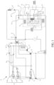
- the present application provides a thermal management system 10.
- the thermal management system 10 includes a refrigerant circuit 20 and a water circuit 30.
- the liquid refrigerant is provided in the refrigerant circuit 20.
- the refrigerant circuit 20 includes a corresponding circuit formed through a plurality of components among a compressor 21, a first heat exchanger 22, a second heat exchanger 23, a condenser 24, a first evaporator 25, a second evaporator 26, a first expansion valve 27, a second expansion valve 28, and a third expansion valve 29 according to needs.
- the water circuit 30 is provided with a cooling liquid, and the water circuit 30 includes a corresponding circuit formed through a plurality of components among a first heat exchanger 22, a first water pump 31, a drive assembly 32, a first four-way valve 33, a second four-way valve 34, a battery assembly 35, a second water pump 36, a three-way valve 37, and a second heat exchanger 23 according to needs.
- the first expansion valve 27, the second expansion valve 28 and the third expansion valve 29 are all configured to throttle the refrigerant circuit 20, thereby reducing the temperature of the liquid refrigerant.
- the first evaporator 25, the second evaporator 26 and the condenser 24 are all configured to adjust the temperature in the passenger compartment.
- the first evaporator 25 and the condenser 24 are configured to adjust the temperature in the front passenger compartment
- the second evaporator 26 is configured to adjust the temperature in the rear passenger compartment
- the first heat exchanger 22 is connected in parallel with the water circuit 30, so as to recycle the heat generated by the drive assembly 32.
- the second heat exchanger 23 is also connected in parallel with the water circuit 30, so as to heat the battery assembly 35.
- the first heat exchanger 22 and the second heat exchanger 23 can be a water heat exchanger or a chiller heat exchanger, etc.
- the compressor 21 is configured to heat the refrigerant circuit 20.
- the drive assembly 32 is configured to heat the water circuit 30 or the refrigerant circuit 20.
- the first water pump 31 and the second water pump 36 are configured to drive and adjust the flow of the cooling liquid in the water circuit 30.
- the first four-way valve 33, the second four-way valve 34 and the three-way valve 37 are configured to change the flowing direction of the cooling liquid in the water circuit 30, and the refrigerant circuit 20 and the water circuit 30 are provided with a plurality of control valves to form corresponding circuits according to the needs of different heat management modes, and interact with each other to achieve a preset effect.
- the first four-way valve 33, the second four-way valve 34 and the three-way valve 37 configured in the heat management system are all multi-pass control valves, which can not only control the flowing direction of the water circuit 30, but also control the flow of the cooling liquid, so that the thermal management system 10 can freely distribute the flow according to actual needs, thereby improving the energy efficiency of the system and the stability of system control.
- the multi-way control valve can also be replaced by a control valve group to control the flowing direction of the cooling liquid in the water circuit 30.
- the heater is first turned on to heat the refrigerant circuit 20, so as to ensure that the compressor 21, the condenser 24, the first evaporator 25 and the second evaporator 26 are smoothly turned on, and the heater can be a PTC heater. Since the heating efficiency of the PTC heater is lower than 1, the start of the PTC heater will increase the energy consumption of the whole vehicle and thus affect the cruising range. In this solution, there is no need for an additional heater.
- the heat generated by the recycle drive assembly 32 of the first heat exchanger 22 is configured to heat the liquid refrigerant in the refrigerant circuit 20, so that the compressor 21, the condenser 24, the first evaporator 25 and the second evaporator 26 can be turned on smoothly, thereby reducing the vehicle energy consumption.
- the refrigerant circuit 20 and the water circuit 30 are provided.
- the refrigerant circuit 20 includes a corresponding circuit formed through a plurality of components among the compressor 21, the first heat exchanger 22, the second heat exchanger 23, the condenser 24, the first evaporator 25, the second evaporator 26, the first expansion valve 27, the second expansion valve 28, and the third expansion valve 29 according to needs.
- the water circuit 30 is provided with the cooling liquid.
- the water circuit 30 includes a corresponding circuit formed through a plurality of components among the first heat exchanger 22, the first water pump 31, the drive assembly 32, the first four-way valve 33, the second four-way valve 34, the battery assembly 35, the second water pump 36, the three-way valve 37, and the second heat exchanger 23 according to needs.
- the refrigerant circuit 20 and the water circuit 30 in this embodiment are simpler, and no additional heater is required.
- the heat generated by the recycle drive assembly 32 of the first heat exchanger 22 is configured to heat the liquid refrigerant in the refrigerant circuit 20, so that the compressor 21, the condenser 24, the first evaporator 25 and the second evaporator 26 are turned on smoothly, thereby reducing the energy consumption of the vehicle.
- the thermal management system 10 further includes an air conditioner main unit 40.
- the air conditioner main unit 40 includes a first heat exchange air duct 41, a second heat exchange air duct 42 and a circulating air duct 43.
- the first heat exchange air duct 41 is provided with a condenser 24, and the first heat exchange air duct 41 is provided with a first air inlet end 411 and a first air outlet end 412.
- the first air inlet end 411 includes a first air inlet 414 communicated with a circulating air inlet and a second air inlet 415 communicated with an outside of the vehicle, and the first air outlet end 412 is respectively communicated with a first air outlet 416 communicated with an inside of the vehicle and a second air outlet 417 communicated with the outside of the vehicle.
- the second heat exchange air duct 42 is provided with a first evaporator 25, and the second heat exchange air duct 42 is provided with a second air inlet end 421 and a second air outlet end 422.
- the second air inlet end 421 includes a third air inlet 423 communicated with a circulating air inlet and a fourth air inlet 424 communicated with the outside of the vehicle.
- the second air outlet end 422 is respectively communicated with third air outlet 425 communicated with the inside of the vehicle and a fourth air outlet 426 communicated with the outside of the vehicle.
- the circulating air duct 43 is configured to recycle air after heat exchange through the first heat exchange air duct 41, and circulate it to the first air inlet 414.
- the circulating air inlet includes an in-vehicle circulating air inlet 413.
- One end of the in-vehicle circulating air inlet 413 is communicated with the in-vehicle, and the other end of the in-vehicle circulating air inlet 413 is communicated with the first air inlet 414 and the third air inlet 423.
- the air inlet end of the circulating air duct 43 is communicated with the first air outlet end 412, and the air outlet end of the circulating air duct 43 can be connected to the first air inlet end 411 so as to be communicated with the first air inlet 414, or connected between the in-vehicle circulating air inlet 413 and the first air inlet 414.
- the first heat exchange air duct 41 is provided with a condenser 24 configured to heat the air in the first heat exchange air duct 41. Therefore, in the heating mode, the fresh air formed by the external air being filtered through the vehicle air filtration system enters the first heat exchange air duct 41 through the second air inlet 415, and the air heated by the first heat exchange air duct 41 passes through the first air outlet end 412 and is discharged into the vehicle through the first air outlet 416, so as to heat the vehicle.
- the fresh air formed by the external air being filtered through the vehicle air filtration system enters the second heat exchange air duct 42 through the fourth air inlet 424, and the air cooled by the second heat exchange air duct 42 passes through the second air outlet end 422 and is discharged outside the vehicle through the fourth air outlet 426, so as to complete the air flow direction in the heating mode, and heat the vehicle.
- the "communicated with” indicated in the present application only indicates the connection relationship between different ventilation ducts, and does not represent their communicated status. Whether they are communicated or whether each air duct is blocked is controlled by its corresponding control switch.
- the first air outlet end 412 is respectively communicated with the first air outlet 416 communicated with the inside of the vehicle and the second air outlet 417 communicated with the outside of the vehicle.
- the first air outlet end 412 can be only communicated with the first air outlet 416, or can be only communicated with the second air outlet 417, or can be communicated with both the first air outlet 416 and the second air outlet 417.
- the meaning of that the first air outlet end 412 refers to a section of the air duct between the location of the condenser 24 and the first air outlet 416 and the second air outlet 417, and the first air outlet end 412 is respectively communicated with the first air outlet 416 and the second air outlet 417 can be: the first air outlet end 412 is directly communicated with the first air outlet 416 and the second air outlet 417, that is, the first air outlet 416 and the second air outlet 417 are directly opened at the end of the first air outlet end 412 away from the condenser 24; or the first air outlet end 412 is indirectly connected to the first air outlet 416 and the second air outlet 417.
- first air outlet end 412 is respectively connected to the first air outlet 416 and the second air outlet 417 through a preset air duct.
- the second heat exchange air duct 42 is provided with a first evaporator 25 configured to cool the air in the second heat exchange air duct 42.
- the meaning of that the second air outlet end 422 refers to a section of the air duct between the location of the first evaporator 25 and the third air outlet 425 and the fourth air outlet 426, and the second air outlet end 422 is respectively communicated with the third air outlet 425 and the fourth air outlet 426 can be: the second air outlet end 422 is directly communicated with the third air outlet 425 and the fourth air outlet 426, that is, the third air outlet 425 and the fourth air outlet 426 are directly opened in the second air outlet end 422; or the second air outlet end 422 is indirectly connected to the third air outlet 425 and the fourth air outlet 426.
- the second air outlet end 422 is respectively connected to the third air outlet 425 and the fourth air outlet 426 through the preset air duct.
- the outdoor ambient temperature is very low. Therefore, the temperature of the fresh air sucked from the outside by the first heat exchange air duct 41 is also very low, which may cause the suction temperature and suction pressure of the compressor 21 to be too low, and is not conducive to the heat exchange of the condenser 24, resulting in the difficulty of the thermal management system 10 to quickly enter the working state and the heating rate to slow down.
- the circulating air duct 43 is provided to recycle the air after heat exchange through the first heat exchange air duct 41, so as to increase the inlet air temperature of the first evaporator 25 within a period of time after the air conditioner main unit 40 is just started, thereby facilitating the air conditioning system to quickly enter the working state.
- the circulating air duct 43 can recycle the air heated by the condenser 24 to the second heat exchange air duct 42, increase the temperature of the air entering the second heat exchange air duct 42 so as to assist the first evaporator 25 in heat exchange, and increase the temperature of the liquid refrigerant in the first evaporator 25 so as to increase the temperature of the liquid refrigerant through the flow of the liquid refrigerant in the refrigerant circuit 20, thereby facilitating the air conditioner main unit 40 to quickly enter the working state.
- the switching of different working modes or states of the air conditioner main unit 40 can be adapted.
- the conduction and blocking of the first air inlet 414, the second air inlet 415, the third air inlet 423, the fourth air inlet 424, the first air outlet 416, the second air outlet 417, the third air outlet 425, the fourth air outlet 426 and the circulating air inlet can be adjusted according to the switching of different working modes or states of the thermal management system 10.
- the refrigerant circuit 20 includes a first circuit and a second circuit.
- the first circuit is a closed circuit formed by the compressor 21, the second heat exchanger 23, the condenser 24, the first expansion valve 27 and the first heat exchanger 22 connected in series.
- the second circuit is a closed circuit formed by the first evaporator 25, the second expansion valve 28, the third expansion valve 29 and the second evaporator 26 connected in series.
- a flow channel between the second evaporator 26 and the first evaporator 25 is connected in series to a flow channel between the compressor 21 and the first heat exchanger 22, and a flow channel between the second expansion valve 28 and the third expansion valve 29 is connected in series to a flow channel between the condenser 24 and the first expansion valve 27.
- the flow direction of the liquid refrigerant will be described below by taking the first heat exchanger 22 as the starting point of the refrigerant as an example.
- the liquid refrigerant further heated by the compressor 21 passes through the second heat exchanger 23, and transfers the heat to the battery assembly 35, thereby heating the battery assembly 35 and improving the working efficiency of the battery assembly 35. Then, the liquid refrigerant flows through the condenser 24 to heat the passenger compartment, and flows back to the first heat exchanger 22 after being throttled again by the first expansion valve 27.
- the liquid refrigerant passes through the first evaporator 25 and passes through the second expansion valve 28 to further cool down, and passes through the third expansion valve 29 and passes through the second evaporator 26 to adjust the temperature and flows back to the first evaporator 25.
- the first circuit and the second circuit undergo two confluences and diversions of the liquid refrigerant, thereby neutralizing the temperature of the liquid refrigerant.
- the first confluence and diversion occurs when the cooling liquid in the first circuit flows between the first heat exchanger 22 and the compressor 21, and the cooling liquid in the second circuit flows between the second evaporator 26 and the first evaporator 25, that is, the flow channel between the first heat exchanger 22 and the compressor 21 is communicated with the flow channel between the second evaporator 26 and the first evaporator 25 through a four-way pipe, thereby mixing the liquid refrigerant and neutralizing the heat of the liquid refrigerant; and the second confluence and diversion occurs when the cooling liquid in the first circuit flows between the condenser 24 and the first expansion valve 27, and the cooling liquid in the second circuit flows between the second expansion valve 28 and the third expansion valve 29, that is, the flow channel between the condenser 24 and the first expansion valve 27 is communicated with the flow channel between the second expansion valve 28 and the third expansion valve 29 through a four-way pipe, thereby mixing the liquid refrigerant and neutralizing the heat of the liquid refrigerant.
- the thermal management system 10 has a first heating state.
- the water circuit 30 includes a motor circuit 50 and a battery circuit 60.
- the motor circuit 50 and the battery circuit 60 are connected in parallel through the first four-way valve 33; the second four-way valve 34, the motor circuit 50 and the refrigerant circuit 20 are connected in parallel through the first heat exchanger 22; and the battery circuit 60 and the refrigerant circuit 20 are connected in parallel through the second heat exchanger 23.
- the motor circuit 50 is a closed circuit formed by the first water pump 31, the drive assembly 32, the first four-way valve 33, the first heat exchanger 22, the second four-way valve 34, and the three-way valve 37 connected in series.
- the battery circuit 60 is a closed circuit formed by the first four-way valve 33, the second heat exchanger 23, the second four-way valve 34, the second water pump 36, and the battery assembly 35 connected in series.
- the flow direction of the liquid refrigerant in the refrigerant circuit 20 is configured as the above-mentioned flow direction.
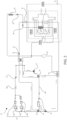
- FIG. 2 is a structural schematic view of the thermal management system 10 of FIG. 1 in a first heating state, and the direction indicated by the arrow in the figure is the flow direction of the cooling liquid in the motor circuit 50 and the battery circuit 60.
- the motor circuit 50 and the battery circuit 60 are connected in parallel through the first four-way valve 33 and the second four-way valve 34, that is, no heat exchange occurs.
- the cooling liquid is driven by the first water pump 31 to reciprocate between the drive assembly 32 and the first heat exchanger 22, and continuously flows through the first four-way valve 33, the second four-way valve 34 and the three-way valve 37, thereby recycling the heat of the drive assembly 32.
- the cooling liquid is driven by the second water pump 36 to reciprocate between the battery assembly 35 and the second heat exchanger 23, and continuously flows through the first four-way valve 33 and the second four-way valve 34, so as to heat the battery assembly 35 and improve the working efficiency of the battery assembly 35.
- the first heating state is the working state when the vehicle thermal management system 10 is just started.
- the air conditioner main unit 40 is first turned on to make the wind wheels in the first heat exchange air duct 41 and the second heat exchange air duct 42 rotate at a low speed. Then the first water pump 31 controls the motor circuit 50 to flow with a small flow rate, so as to quickly heat the cooling liquid and transfer the temperature to the refrigerant circuit 20 through the first heat exchanger 22.
- the compressor 21 starts to work to further heat the liquid refrigerant, thus the related apparatus in the refrigerant circuit 20 can work stably, and the wind wheel speed is increased to make the refrigerant circuit 20 work normally, so that the air conditioner main unit 40 can quickly realize the normal operation of the refrigerant circuit 20 without using a heater to provide the supplement heat.
- the first air inlet 414, the second air inlet 415, the third air inlet 423, the fourth air outlet 426 and the circulating air duct 43 are all turned on, and the in-vehicle circulating air inlet 413, the first air outlet 416, the second air outlet 417, the third air outlet 425 and the fourth air inlet 424 are all blocked, so that the air outside the vehicle enters the first heat exchange air duct 41 for heat exchange and passes through the first circulating air duct 43.
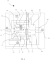
- FIG. 3 is a structural schematic view of the air conditioner main unit 40 when the thermal management system 10 is in the first heating state, and the direction indicated by the arrow in the figure is the flow direction of the airflow in the air conditioner main unit 40.
- the fresh air outside the vehicle enters the first heat exchange air duct 41 from the second air inlet 415, and enters the circulating air duct 43 after being heated by the condenser 24.
- the air outlet end of the circulating air duct 43 is communicated with the first air inlet 414 and the third air inlet 423, so that a part of the air enters from the first air inlet 414 and is neutralized with the fresh air entering from the second air inlet 415 and flows into the first heat exchange air duct 41 together, thereby neutralizing and increasing the inlet temperature of the fresh air, increasing the inlet temperature of the first heat exchange air duct 41, reducing heat waste, and reducing the power required for the condenser 24 to work.
- the other part of the air flows into the second heat exchange air duct 42 from the third air inlet 423 for heat exchange, thereby increasing the inlet air temperature of the second heat exchange air duct 42.
- the first evaporator 25 recycles the waste heat, assists the first evaporator 25 in heat exchange, and helps the thermal management system 10 to quickly enter the working state. Since the inlet air temperature of the second heat exchange air duct 42 increases, it can also further heat the liquid refrigerant in the refrigerant circuit 20, thereby increasing the refrigerant temperature of the entire refrigerant circuit 20, and improving the heating efficiency. In this embodiment, the air temperature recycling is all completed by the circulating air duct 43, and the air does not pass through the inside of the vehicle. Not only is the heat recycling efficiency high, but also it does not pass through the inside of the vehicle, thus no additional water vapor will be generated.
- the air in the air conditioner main unit 40 is introduced from the inside of the vehicle as a whole and discharged to the outside of the vehicle, which not only effectively recycles heat, but also has less water vapor content in the fresh air outside the vehicle, thereby reducing the possibility of vehicle fogging.
- the thermal management system 10 has a second heating state.
- the water circuit 30 is connected in parallel with the refrigerant circuit 20 respectively through the first heat exchanger 22 and the second heat exchanger 23.
- the water circuit 30 is configured as a closed circuit formed by the first water pump 31, the drive assembly 32, the first four-way valve 33, the second heat exchanger 23, the second four-way valve 34, the second water pump 36, the battery assembly 35, the first four-way valve 33, the first heat exchanger 22, the second four-way valve 34, and the three-way valve 37 connected in series in sequence.
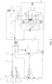
- FIG. 4 is a structural schematic view of the thermal management system 10 in the second heating state, and the direction indicated by the arrow in the figure is the flow direction of the cooling liquid in the water circuit 30.
- the water circuit 30 is a water circuit 30 connected in series in sequence. The flow direction of the cooling liquid is described below by taking the first heat exchanger 22 as the starting point of the cooling liquid as an example.
- the cooling liquid transfers the heat generated by the drive assembly 32 to the refrigerant circuit 20 through the first heat exchanger 22, flows through the drive assembly 32 again and absorbs the heat of the drive assembly 32, flows through the first four-way valve 33 and passes through the second heat exchanger 23 to further heat the cooling liquid, flows through the second four-way valve 34, flows through the battery assembly 35 driven by the second water pump 36 to heat the battery assembly 35, flows through the first four-way valve 33 and the second four-way valve 34 in sequence again, and flows back to the first heat exchanger 22.
- the first heat exchanger 22 recycles the waste heat of the second heat exchanger 23 and the drive assembly 32.
- the second heating state that is, when the thermal management system 10 is in a stable state, requires improving the heat utilization rate in the thermal management system 10 as much as possible.
- the heat generated by the second heat exchanger 23 and the drive assembly 32 is recycled through the first heat exchanger 22, thereby reducing the heat waste in the thermal management system 10, improving the heat utilization rate, and reducing the overall energy consumption of the vehicle.
- the in-vehicle circulating air inlet 413, the first air inlet 414, the second air inlet 415, the fourth air inlet 424, the first air outlet 416 and the fourth air outlet 426 are all communicated, and the third air inlet 423, the second air outlet 417, the third air outlet 425 and the circulating air duct 43 are all blocked, so that the air after heat exchange through the first heat exchange air duct 41 is discharged into the vehicle and is circulated again to the first heat exchange air duct 41 together with the air inside the vehicle.
- FIG. 5 FIG.
- FIG. 5 is a structural schematic view of the air conditioner main unit 40 when the thermal management system 10 is in the second heating state, and the direction indicated by the arrow in the figure is the flow direction of the airflow in the air conditioner main unit 40.
- the first heating state is switched to the second heating state, so that the fresh air outside the vehicle enters the first heat exchange air duct 41 through the second air inlet 415, and the air heated by the condenser 24 flows into the vehicle through the first air outlet 416.
- the air flows into the first air inlet 414 again from the in-vehicle circulating air inlet 413, so that the air is neutralized with the fresh air entering from the second air inlet 415 and flows into the first heat exchange air duct 41 together, thereby neutralizing and increasing the inlet temperature of the fresh air, increasing the temperature of the first heat exchange air duct 41, and reducing the heat waste and the power required for the operation of the condenser 24.
- the fresh air outside the vehicle enters the second heat exchange air duct 42 from the fourth air inlet 424, and the first evaporator 25 discharges the air from the fourth air outlet 426 after the heat exchange is carried out normally.
- the drive assembly 32 includes a first drive motor 321, a first control assembly 322, a second drive motor 323 and a second control assembly 324.
- the water circuit 30 includes a first branch and a second branch arranged in parallel.
- the first drive motor 321 and the first control assembly 322 are connected in series to the first branch; and the second drive motor 323 and the second control assembly 324 are connected in series to the second branch.
- the first drive motor 321 is a front drive motor
- the second drive motor 323 is a rear drive motor.
- the first branch and the second branch are arranged in parallel.
- this solution can increase the flow of the cooling liquid in the water circuit 30, increase the heat recycling efficiency of the drive assembly 32, and reduce the heat loss.
- the first branch and the second branch can also be arranged in parallel.
- the thermal management system 10 further includes a first liquid storage apparatus 70 communicated with the refrigerant circuit 20 to replenish the refrigerant circuit 20.
- the first liquid storage apparatus 70 can be provided at any position of the refrigerant circuit 20.
- the first liquid storage apparatus 70 is after the condenser 24, so as to facilitate the subsequent heat neutralization of the first circuit and the second circuit.
- the thermal management system 10 further includes a second liquid storage apparatus 80 communicated with the water circuit 30 to replenish the water circuit 30.
- the second liquid storage apparatus 80 can be provided at any position of the water circuit 30.
- the second liquid storage apparatus 80 is communicated with the first water pump 31 and the second water pump 36 respectively. Since the first water pump 31 and the second water pump 36 can both speed up the flow of water, the efficiency of replenishment is improved.
- the present application also provides a vehicle, including the thermal management system 10.
- the specific structure of the thermal management system 10 refers to the above-mentioned embodiment. Since the vehicle adopts all the technical solutions of all the above-mentioned embodiments, it has at least all the beneficial effects brought by the technical solutions of the above-mentioned embodiments, which will not be repeated here.
Landscapes
- Engineering & Computer Science (AREA)
- Physics & Mathematics (AREA)
- Thermal Sciences (AREA)
- Mechanical Engineering (AREA)
- Chemical & Material Sciences (AREA)
- Manufacturing & Machinery (AREA)
- Chemical Kinetics & Catalysis (AREA)
- Electrochemistry (AREA)
- General Chemical & Material Sciences (AREA)
- Combustion & Propulsion (AREA)
- Air-Conditioning For Vehicles (AREA)
Abstract
Disclosed are a thermal management system and a vehicle. The thermal management system includes a refrigerant circuit and a water circuit. The refrigerant circuit is provided with a liquid refrigerant and includes a corresponding circuit formed through a plurality of components among a compressor, a first heat exchanger, a second heat exchanger, a condenser, a first evaporator, a second evaporator, a first expansion valve, a second expansion valve, and a third expansion valve according to needs. The water circuit is provided with a cooling liquid and includes a corresponding circuit formed through a plurality of components among the first heat exchanger, a first water pump, a drive assembly, a first four-way valve, a second four-way valve, a battery assembly, a second water pump, a three-way valve, and the second heat exchanger according to needs.
Description
- The present application claims priority to
Chinese Patent Application No. 202211512426.6, filed on November 29, 2022 - The present application relates to the technical field of vehicles, and in particular to a thermal management system and a vehicle.
- At present, the thermal comfort and heating function of new energy vehicles are relatively large problems compared with traditional fuel vehicles. The majority of producers adopt the heat pump system and the positive temperature coefficient (PTC) heater to solve this problem.
- However, the thermal management system using the heat pump system and the PTC heater still has some defects. For example, the present heat pump system is complicated to switch between cooling and heating for passenger compartment, which needs the compressor to stop working, the functional needs can only be achieved by adjusting the on/off valve and different electronic expansion valves, and the PTC heater is also required to provide supplement heat. However, since the heating efficiency of the PTC heater is lower than 1, the start of the PTC heater will increase the energy consumption of the whole vehicle and thus affect the cruising range
- The main purpose of the present application is to provide a thermal management system, aiming to simplify the thermal management system and reduce the energy consumption of the whole vehicle.
- To achieve the above purpose, the thermal management system provided in the present application includes:
- a refrigerant circuit provided with a liquid refrigerant and including a corresponding circuit formed through a plurality of components among a compressor, a first heat exchanger, a second heat exchanger, a condenser, a first evaporator, a second evaporator, a first expansion valve, a second expansion valve, and a third expansion valve according to needs; and
- a water circuit provided with a cooling liquid and including a corresponding circuit formed through a plurality of components among the first heat exchanger, a first water pump, a drive assembly, a first four-way valve, a second four-way valve, a battery assembly, a second water pump, a three-way valve, and a second heat exchanger according to needs.
- In an embodiment, the thermal management system further includes: an air conditioner main unit including a first heat exchange air duct, a second heat exchange air duct and a circulating air duct; the first heat exchange air duct is provided with a condenser, a first air inlet end and a first air outlet end, the first air inlet end includes a first air inlet communicated with a circulating air inlet and a second air inlet communicated with an outside of a vehicle, and the first air outlet end is respectively communicated with a first air outlet communicated with an inside of the vehicle and a second air outlet communicated with the outside of the vehicle;
- the second heat exchange air duct is provided with a first evaporator, a second air inlet end and a second air outlet end, the second air inlet end includes a third air inlet communicated with the circulating air inlet and a fourth air outlet communicated with the outside of the vehicle, and the second air outlet end is respectively communicated with the third air outlet communicated with the inside of the vehicle and the fourth air outlet communicated with the outside of the vehicle; and
- the circulating air duct is configured to recycle an air after heat exchange through the first heat exchange air duct and circulate the air to the first air inlet.
- In an embodiment, the refrigerant circuit includes a first circuit and a second circuit, the first circuit is a closed circuit formed by the compressor, the second heat exchanger, the condenser, the first expansion valve, and the first heat exchanger connected in series in sequence, the second circuit is a closed circuit formed by the first evaporator, the second expansion valve, the third expansion valve, and the second evaporator connected in series in sequence, a flow channel between the second evaporator and the first evaporator is connected in series with a flow channel between the compressor and the first heat exchanger, and a flow channel between the second expansion valve and the third expansion valve is connected in series with a flow channel between the condenser and the first expansion valve.
- In an embodiment, the thermal management system has a first heating state;
- in the first heating state, the water circuit includes a motor circuit and a battery circuit connected in parallel through the first four-way valve and the second four-way valve, the motor circuit and the refrigerant circuit are connected in parallel through the first heat exchanger, and the battery circuit and the refrigerant circuit are connected in parallel through the second heat exchanger;
- the motor circuit is a closed circuit formed by the first water pump, the drive assembly, the first four-way valve, the first heat exchanger, the second four-way valve, and the three-way valve connected in series in sequence; and
- the battery circuit is a closed circuit formed by the first four-way valve, the second heat exchanger, the second four-way valve, the second water pump, and the battery assembly connected in series in sequence.
- In an embodiment, in the first heating state, the first air inlet, the second air inlet, the third air inlet, the fourth air outlet and the circulating air duct are all communicated, and the in-vehicle circulating air inlet, the first air outlet, the second air outlet, the third air outlet and the fourth air inlet are all blocked, so that an air outside the vehicle is configured to enter the first heat exchange air duct for heat exchange and pass through the first circulating air duct; and a part of the air is configured to enter the first air inlet to continue circulation, and another part of the air is configured to flow into the second heat exchange air duct through the third air inlet for heat exchange and is discharged out of the vehicle.
- In an embodiment, the thermal management system has a second heating state; and
in the second heating state, the water circuit is connected in parallel with the refrigerant circuit through the first heat exchanger and the second heat exchanger respectively, and the water circuit is configured as a closed circuit formed by the first water pump, the drive assembly, the first four-way valve, the second heat exchanger, the second four-way valve, the second water pump, the battery assembly, the first four-way valve, the first heat exchanger, the second four-way valve, and the three-way valve connected in series in sequence. - In an embodiment, in the second heating state, the in-vehicle circulating air inlet, the first air inlet, the second air inlet, the fourth air inlet, the first air outlet and the fourth air outlet are all communicated, and the third air inlet, the second air outlet, the third air outlet and the circulating air duct are all blocked, so that the air after heat exchange through the first heat exchange air duct is discharged into the vehicle and is circulated to the first heat exchange air duct together with an air inside the vehicle.
- In an embodiment, the drive assembly includes a first drive motor, a first control assembly, a second drive motor and a second control assembly, the water circuit includes a first branch and a second branch provided in parallel, the first drive motor and the first control assembly are connected in series to the first branch, and the second drive motor and the second control assembly are connected in series to the second branch.
- In an embodiment, the thermal management system further includes: a first liquid storage apparatus communicated with the refrigerant circuit to replenish the refrigerant circuit; and/or
a second liquid storage apparatus communicated with the water circuit to replenish the water circuit. - The present application also provides a vehicle, including the thermal management system.
- In the technical solution of the present application, a refrigerant circuit and a water circuit are provided. The refrigerant circuit includes a corresponding circuit formed through a plurality of components among a compressor, a first heat exchanger, a second heat exchanger, a condenser, a first evaporator, a second evaporator, a first expansion valve, a second expansion valve, and a third expansion valve according to needs. The water circuit is provided with the cooling liquid, and the water circuit includes a corresponding circuit formed through a plurality of components among the first heat exchanger, a first water pump, a drive assembly, a first four-way valve, a second four-way valve, a battery assembly, a second water pump, a three-way valve, and a second heat exchanger according to needs.. Compared with the thermal management system with the heat pump system and the heater in the related art, the refrigerant circuit and the water circuit in the present application are simpler, and there is no need for an additional heater. The heat generated by the recycle drive assembly of the first heat exchanger is used to heat the liquid refrigerant in the refrigerant circuit, so that the compressor, the condenser, the first evaporator and the second evaporator are turned on smoothly, thereby reducing the energy consumption of the vehicle.
- In order to illustrate the technical solutions in the embodiments of the present application or in the related art more clearly, the following briefly introduces the accompanying drawings required for the description of the embodiments or the related art. Obviously, the drawings in the following description are only part of embodiments of the present application. For those skilled in the art, other drawings can also be obtained according to the structures shown in these drawings without any creative effort.
-
FIG. 1 is a structural schematic view of a thermal management system according to an embodiment of the present application. -
FIG. 2 is a structural schematic view of the thermal management system ofFIG. 1 in a first heating state. -
FIG. 3 is a partially enlarged view at A inFIG. 2 . -
FIG. 4 is a structural schematic view of the thermal management system ofFIG. 1 in a second heating state. -
FIG. 5 is a partially enlarged view at B inFIG. 4 . - The realization of the objective, functional characteristics, and advantages of the present application are further described with reference to the accompanying drawings.
- The technical solutions of the embodiments of the present application will be described in more detail below with reference to the accompanying drawings. It is obvious that the embodiments to be described are only some rather than all of the embodiments of the present application. All other embodiments obtained by those skilled in the art based on the embodiments of the present application without creative efforts shall fall within the scope of the present application.
- It should be noted that all directional indications (such as up, down, left, right, front, back, etc.) in the embodiments of the present application are only used to explain the relative positional relationship, the movement situation, etc. If the specific posture changes, the directional indication also changes accordingly.
- In addition, the descriptions of "first", "second", etc. are only for the purpose of description, and should not be construed as indicating or implying relative importance or implicitly indicates the number of technical features indicated. Thus, a feature delimited with "first", "second" may expressly or implicitly include at least one of that feature. In addition, the meaning of "and/or" in the present application includes three parallel schemes, taking "A and/or B" as an example, including scheme A, or scheme B, or scheme A and B at the same time. In addition, the technical solutions between the various embodiments can be combined with each other, but must be based on the realization by those skilled in the art. When the combination of technical solutions is contradictory or cannot be realized, it should be considered that the combination of such technical solutions does not exist or fall within the scope of protection claimed in the present application.
- The present application provides a
thermal management system 10. - In an embodiment of the present application, as shown in
FIG. 1 , thethermal management system 10 includes arefrigerant circuit 20 and a water circuit 30. The liquid refrigerant is provided in therefrigerant circuit 20. Therefrigerant circuit 20 includes a corresponding circuit formed through a plurality of components among acompressor 21, afirst heat exchanger 22, asecond heat exchanger 23, acondenser 24, afirst evaporator 25, asecond evaporator 26, afirst expansion valve 27, asecond expansion valve 28, and athird expansion valve 29 according to needs. The water circuit 30 is provided with a cooling liquid, and the water circuit 30 includes a corresponding circuit formed through a plurality of components among afirst heat exchanger 22, afirst water pump 31, adrive assembly 32, a first four-way valve 33, a second four-way valve 34, abattery assembly 35, asecond water pump 36, a three-way valve 37, and asecond heat exchanger 23 according to needs. - Specifically, in the
refrigerant circuit 20, thefirst expansion valve 27, thesecond expansion valve 28 and thethird expansion valve 29 are all configured to throttle therefrigerant circuit 20, thereby reducing the temperature of the liquid refrigerant. Thefirst evaporator 25, thesecond evaporator 26 and thecondenser 24 are all configured to adjust the temperature in the passenger compartment. Thefirst evaporator 25 and thecondenser 24 are configured to adjust the temperature in the front passenger compartment, thesecond evaporator 26 is configured to adjust the temperature in the rear passenger compartment, and thefirst heat exchanger 22 is connected in parallel with the water circuit 30, so as to recycle the heat generated by thedrive assembly 32. Thesecond heat exchanger 23 is also connected in parallel with the water circuit 30, so as to heat thebattery assembly 35. Thefirst heat exchanger 22 and thesecond heat exchanger 23 can be a water heat exchanger or a chiller heat exchanger, etc. Thecompressor 21 is configured to heat therefrigerant circuit 20. In the water circuit 30, thedrive assembly 32 is configured to heat the water circuit 30 or therefrigerant circuit 20. Thefirst water pump 31 and thesecond water pump 36 are configured to drive and adjust the flow of the cooling liquid in the water circuit 30. The first four-way valve 33, the second four-way valve 34 and the three-way valve 37 are configured to change the flowing direction of the cooling liquid in the water circuit 30, and therefrigerant circuit 20 and the water circuit 30 are provided with a plurality of control valves to form corresponding circuits according to the needs of different heat management modes, and interact with each other to achieve a preset effect. The first four-way valve 33, the second four-way valve 34 and the three-way valve 37 configured in the heat management system are all multi-pass control valves, which can not only control the flowing direction of the water circuit 30, but also control the flow of the cooling liquid, so that thethermal management system 10 can freely distribute the flow according to actual needs, thereby improving the energy efficiency of the system and the stability of system control. Of course, in other embodiments, the multi-way control valve can also be replaced by a control valve group to control the flowing direction of the cooling liquid in the water circuit 30. - In the related art, due to the low temperature in the cold winter, it is difficult to start the
refrigerant circuit 20 by itself, so a heater is often needed for supplementary heating. When thethermal management system 10 is working, the heater is first turned on to heat therefrigerant circuit 20, so as to ensure that thecompressor 21, thecondenser 24, thefirst evaporator 25 and thesecond evaporator 26 are smoothly turned on, and the heater can be a PTC heater. Since the heating efficiency of the PTC heater is lower than 1, the start of the PTC heater will increase the energy consumption of the whole vehicle and thus affect the cruising range. In this solution, there is no need for an additional heater. The heat generated by therecycle drive assembly 32 of thefirst heat exchanger 22 is configured to heat the liquid refrigerant in therefrigerant circuit 20, so that thecompressor 21, thecondenser 24, thefirst evaporator 25 and thesecond evaporator 26 can be turned on smoothly, thereby reducing the vehicle energy consumption. - In the technical solution of the present application, the
refrigerant circuit 20 and the water circuit 30 are provided. Therefrigerant circuit 20 includes a corresponding circuit formed through a plurality of components among thecompressor 21, thefirst heat exchanger 22, thesecond heat exchanger 23, thecondenser 24, thefirst evaporator 25, thesecond evaporator 26, thefirst expansion valve 27, thesecond expansion valve 28, and thethird expansion valve 29 according to needs. The water circuit 30 is provided with the cooling liquid. The water circuit 30 includes a corresponding circuit formed through a plurality of components among thefirst heat exchanger 22, thefirst water pump 31, thedrive assembly 32, the first four-way valve 33, the second four-way valve 34, thebattery assembly 35, thesecond water pump 36, the three-way valve 37, and thesecond heat exchanger 23 according to needs. Compared with thethermal management system 10 using a heat pump system and a heater in the related art, therefrigerant circuit 20 and the water circuit 30 in this embodiment are simpler, and no additional heater is required. The heat generated by therecycle drive assembly 32 of thefirst heat exchanger 22 is configured to heat the liquid refrigerant in therefrigerant circuit 20, so that thecompressor 21, thecondenser 24, thefirst evaporator 25 and thesecond evaporator 26 are turned on smoothly, thereby reducing the energy consumption of the vehicle. - Referring to
FIG. 1 to FIG. 5 , in an embodiment, thethermal management system 10 further includes an air conditionermain unit 40. The air conditionermain unit 40 includes a first heatexchange air duct 41, a second heatexchange air duct 42 and a circulating air duct 43. The first heatexchange air duct 41 is provided with acondenser 24, and the first heatexchange air duct 41 is provided with a firstair inlet end 411 and a firstair outlet end 412. The firstair inlet end 411 includes afirst air inlet 414 communicated with a circulating air inlet and asecond air inlet 415 communicated with an outside of the vehicle, and the firstair outlet end 412 is respectively communicated with afirst air outlet 416 communicated with an inside of the vehicle and asecond air outlet 417 communicated with the outside of the vehicle. - The second heat
exchange air duct 42 is provided with afirst evaporator 25, and the second heatexchange air duct 42 is provided with a secondair inlet end 421 and a secondair outlet end 422. The secondair inlet end 421 includes athird air inlet 423 communicated with a circulating air inlet and afourth air inlet 424 communicated with the outside of the vehicle. The secondair outlet end 422 is respectively communicated withthird air outlet 425 communicated with the inside of the vehicle and afourth air outlet 426 communicated with the outside of the vehicle. - The circulating air duct 43 is configured to recycle air after heat exchange through the first heat
exchange air duct 41, and circulate it to thefirst air inlet 414. - Specifically, the circulating air inlet includes an in-vehicle circulating
air inlet 413. One end of the in-vehicle circulatingair inlet 413 is communicated with the in-vehicle, and the other end of the in-vehicle circulatingair inlet 413 is communicated with thefirst air inlet 414 and thethird air inlet 423. The air inlet end of the circulating air duct 43 is communicated with the firstair outlet end 412, and the air outlet end of the circulating air duct 43 can be connected to the firstair inlet end 411 so as to be communicated with thefirst air inlet 414, or connected between the in-vehicle circulatingair inlet 413 and thefirst air inlet 414. The first heatexchange air duct 41 is provided with acondenser 24 configured to heat the air in the first heatexchange air duct 41. Therefore, in the heating mode, the fresh air formed by the external air being filtered through the vehicle air filtration system enters the first heatexchange air duct 41 through thesecond air inlet 415, and the air heated by the first heatexchange air duct 41 passes through the firstair outlet end 412 and is discharged into the vehicle through thefirst air outlet 416, so as to heat the vehicle. The fresh air formed by the external air being filtered through the vehicle air filtration system enters the second heatexchange air duct 42 through thefourth air inlet 424, and the air cooled by the second heatexchange air duct 42 passes through the secondair outlet end 422 and is discharged outside the vehicle through thefourth air outlet 426, so as to complete the air flow direction in the heating mode, and heat the vehicle. It should be noted that the "communicated with" indicated in the present application only indicates the connection relationship between different ventilation ducts, and does not represent their communicated status. Whether they are communicated or whether each air duct is blocked is controlled by its corresponding control switch. For example, the firstair outlet end 412 is respectively communicated with thefirst air outlet 416 communicated with the inside of the vehicle and thesecond air outlet 417 communicated with the outside of the vehicle. The firstair outlet end 412 can be only communicated with thefirst air outlet 416, or can be only communicated with thesecond air outlet 417, or can be communicated with both thefirst air outlet 416 and thesecond air outlet 417. In this embodiment, the meaning of that the firstair outlet end 412 refers to a section of the air duct between the location of thecondenser 24 and thefirst air outlet 416 and thesecond air outlet 417, and the firstair outlet end 412 is respectively communicated with thefirst air outlet 416 and thesecond air outlet 417 can be: the firstair outlet end 412 is directly communicated with thefirst air outlet 416 and thesecond air outlet 417, that is, thefirst air outlet 416 and thesecond air outlet 417 are directly opened at the end of the firstair outlet end 412 away from thecondenser 24; or the firstair outlet end 412 is indirectly connected to thefirst air outlet 416 and thesecond air outlet 417. For example the firstair outlet end 412 is respectively connected to thefirst air outlet 416 and thesecond air outlet 417 through a preset air duct. The second heatexchange air duct 42 is provided with afirst evaporator 25 configured to cool the air in the second heatexchange air duct 42. In this embodiment, the meaning of that the secondair outlet end 422 refers to a section of the air duct between the location of thefirst evaporator 25 and thethird air outlet 425 and thefourth air outlet 426, and the secondair outlet end 422 is respectively communicated with thethird air outlet 425 and thefourth air outlet 426 can be: the secondair outlet end 422 is directly communicated with thethird air outlet 425 and thefourth air outlet 426, that is, thethird air outlet 425 and thefourth air outlet 426 are directly opened in the secondair outlet end 422; or the secondair outlet end 422 is indirectly connected to thethird air outlet 425 and thefourth air outlet 426. For example, the secondair outlet end 422 is respectively connected to thethird air outlet 425 and thefourth air outlet 426 through the preset air duct. - However, in actual operation, especially in extremely cold or hot seasons, such as in cold winter, the outdoor ambient temperature is very low. Therefore, the temperature of the fresh air sucked from the outside by the first heat
exchange air duct 41 is also very low, which may cause the suction temperature and suction pressure of thecompressor 21 to be too low, and is not conducive to the heat exchange of thecondenser 24, resulting in the difficulty of thethermal management system 10 to quickly enter the working state and the heating rate to slow down. Therefore, the circulating air duct 43 is provided to recycle the air after heat exchange through the first heatexchange air duct 41, so as to increase the inlet air temperature of thefirst evaporator 25 within a period of time after the air conditionermain unit 40 is just started, thereby facilitating the air conditioning system to quickly enter the working state. The circulating air duct 43 can recycle the air heated by thecondenser 24 to the second heatexchange air duct 42, increase the temperature of the air entering the second heatexchange air duct 42 so as to assist thefirst evaporator 25 in heat exchange, and increase the temperature of the liquid refrigerant in thefirst evaporator 25 so as to increase the temperature of the liquid refrigerant through the flow of the liquid refrigerant in therefrigerant circuit 20, thereby facilitating the air conditionermain unit 40 to quickly enter the working state. By controlling the on/off of the circulating air duct 43, the switching of different working modes or states of the air conditionermain unit 40 can be adapted. Moreover, the conduction and blocking of thefirst air inlet 414, thesecond air inlet 415, thethird air inlet 423, thefourth air inlet 424, thefirst air outlet 416, thesecond air outlet 417, thethird air outlet 425, thefourth air outlet 426 and the circulating air inlet can be adjusted according to the switching of different working modes or states of thethermal management system 10. - In an embodiment, referring to
FIG. 1 ,FIG. 2 andFIG. 4 , therefrigerant circuit 20 includes a first circuit and a second circuit. The first circuit is a closed circuit formed by thecompressor 21, thesecond heat exchanger 23, thecondenser 24, thefirst expansion valve 27 and thefirst heat exchanger 22 connected in series. The second circuit is a closed circuit formed by thefirst evaporator 25, thesecond expansion valve 28, thethird expansion valve 29 and thesecond evaporator 26 connected in series. A flow channel between thesecond evaporator 26 and thefirst evaporator 25 is connected in series to a flow channel between thecompressor 21 and thefirst heat exchanger 22, and a flow channel between thesecond expansion valve 28 and thethird expansion valve 29 is connected in series to a flow channel between thecondenser 24 and thefirst expansion valve 27. Specifically, the flow direction of the liquid refrigerant will be described below by taking thefirst heat exchanger 22 as the starting point of the refrigerant as an example. In the first circuit, after thefirst heat exchanger 22 recycles the heat generated by thedrive assembly 32 to increase the temperature of the liquid refrigerant, the liquid refrigerant further heated by thecompressor 21 passes through thesecond heat exchanger 23, and transfers the heat to thebattery assembly 35, thereby heating thebattery assembly 35 and improving the working efficiency of thebattery assembly 35. Then, the liquid refrigerant flows through thecondenser 24 to heat the passenger compartment, and flows back to thefirst heat exchanger 22 after being throttled again by thefirst expansion valve 27. In the second circuit, the liquid refrigerant passes through thefirst evaporator 25 and passes through thesecond expansion valve 28 to further cool down, and passes through thethird expansion valve 29 and passes through thesecond evaporator 26 to adjust the temperature and flows back to thefirst evaporator 25. The first circuit and the second circuit undergo two confluences and diversions of the liquid refrigerant, thereby neutralizing the temperature of the liquid refrigerant. The first confluence and diversion occurs when the cooling liquid in the first circuit flows between thefirst heat exchanger 22 and thecompressor 21, and the cooling liquid in the second circuit flows between thesecond evaporator 26 and thefirst evaporator 25, that is, the flow channel between thefirst heat exchanger 22 and thecompressor 21 is communicated with the flow channel between thesecond evaporator 26 and thefirst evaporator 25 through a four-way pipe, thereby mixing the liquid refrigerant and neutralizing the heat of the liquid refrigerant; and the second confluence and diversion occurs when the cooling liquid in the first circuit flows between thecondenser 24 and thefirst expansion valve 27, and the cooling liquid in the second circuit flows between thesecond expansion valve 28 and thethird expansion valve 29, that is, the flow channel between thecondenser 24 and thefirst expansion valve 27 is communicated with the flow channel between thesecond expansion valve 28 and thethird expansion valve 29 through a four-way pipe, thereby mixing the liquid refrigerant and neutralizing the heat of the liquid refrigerant. - Referring to
FIG. 2 , in an embodiment, thethermal management system 10 has a first heating state. In the first heating state, the water circuit 30 includes a motor circuit 50 and a battery circuit 60. The motor circuit 50 and the battery circuit 60 are connected in parallel through the first four-way valve 33; the second four-way valve 34, the motor circuit 50 and therefrigerant circuit 20 are connected in parallel through thefirst heat exchanger 22; and the battery circuit 60 and therefrigerant circuit 20 are connected in parallel through thesecond heat exchanger 23. - The motor circuit 50 is a closed circuit formed by the
first water pump 31, thedrive assembly 32, the first four-way valve 33, thefirst heat exchanger 22, the second four-way valve 34, and the three-way valve 37 connected in series. - The battery circuit 60 is a closed circuit formed by the first four-
way valve 33, thesecond heat exchanger 23, the second four-way valve 34, thesecond water pump 36, and thebattery assembly 35 connected in series. - In an embodiment, in the first heating state, the flow direction of the liquid refrigerant in the
refrigerant circuit 20 is configured as the above-mentioned flow direction. As shown inFIG. 2, FIG. 2 is a structural schematic view of thethermal management system 10 ofFIG. 1 in a first heating state, and the direction indicated by the arrow in the figure is the flow direction of the cooling liquid in the motor circuit 50 and the battery circuit 60. The motor circuit 50 and the battery circuit 60 are connected in parallel through the first four-way valve 33 and the second four-way valve 34, that is, no heat exchange occurs. In the motor circuit 50, the cooling liquid is driven by thefirst water pump 31 to reciprocate between thedrive assembly 32 and thefirst heat exchanger 22, and continuously flows through the first four-way valve 33, the second four-way valve 34 and the three-way valve 37, thereby recycling the heat of thedrive assembly 32. In the battery circuit 60, the cooling liquid is driven by thesecond water pump 36 to reciprocate between thebattery assembly 35 and thesecond heat exchanger 23, and continuously flows through the first four-way valve 33 and the second four-way valve 34, so as to heat thebattery assembly 35 and improve the working efficiency of thebattery assembly 35. The first heating state is the working state when the vehiclethermal management system 10 is just started. At this time, the air conditionermain unit 40 is first turned on to make the wind wheels in the first heatexchange air duct 41 and the second heatexchange air duct 42 rotate at a low speed. Then thefirst water pump 31 controls the motor circuit 50 to flow with a small flow rate, so as to quickly heat the cooling liquid and transfer the temperature to therefrigerant circuit 20 through thefirst heat exchanger 22. After the temperature of the liquid refrigerant in therefrigerant circuit 20 reaches the first temperature, thecompressor 21 starts to work to further heat the liquid refrigerant, thus the related apparatus in therefrigerant circuit 20 can work stably, and the wind wheel speed is increased to make therefrigerant circuit 20 work normally, so that the air conditionermain unit 40 can quickly realize the normal operation of therefrigerant circuit 20 without using a heater to provide the supplement heat. - In an embodiment, referring to
FIG. 3 , in the first heating state, thefirst air inlet 414, thesecond air inlet 415, thethird air inlet 423, thefourth air outlet 426 and the circulating air duct 43 are all turned on, and the in-vehicle circulatingair inlet 413, thefirst air outlet 416, thesecond air outlet 417, thethird air outlet 425 and thefourth air inlet 424 are all blocked, so that the air outside the vehicle enters the first heatexchange air duct 41 for heat exchange and passes through the first circulating air duct 43. After that, part of the air enters thefirst air inlet 414 to continue circulating, and the other part of the air flows into the second heatexchange air duct 42 through thethird air inlet 423 for heat exchange and is discharged out of the vehicle. Specifically, as shown inFIG. 3, FIG. 3 is a structural schematic view of the air conditionermain unit 40 when thethermal management system 10 is in the first heating state, and the direction indicated by the arrow in the figure is the flow direction of the airflow in the air conditionermain unit 40. The fresh air outside the vehicle enters the first heatexchange air duct 41 from thesecond air inlet 415, and enters the circulating air duct 43 after being heated by thecondenser 24. The air outlet end of the circulating air duct 43 is communicated with thefirst air inlet 414 and thethird air inlet 423, so that a part of the air enters from thefirst air inlet 414 and is neutralized with the fresh air entering from thesecond air inlet 415 and flows into the first heatexchange air duct 41 together, thereby neutralizing and increasing the inlet temperature of the fresh air, increasing the inlet temperature of the first heatexchange air duct 41, reducing heat waste, and reducing the power required for thecondenser 24 to work. The other part of the air flows into the second heatexchange air duct 42 from thethird air inlet 423 for heat exchange, thereby increasing the inlet air temperature of the second heatexchange air duct 42. Thefirst evaporator 25 recycles the waste heat, assists thefirst evaporator 25 in heat exchange, and helps thethermal management system 10 to quickly enter the working state. Since the inlet air temperature of the second heatexchange air duct 42 increases, it can also further heat the liquid refrigerant in therefrigerant circuit 20, thereby increasing the refrigerant temperature of the entirerefrigerant circuit 20, and improving the heating efficiency. In this embodiment, the air temperature recycling is all completed by the circulating air duct 43, and the air does not pass through the inside of the vehicle. Not only is the heat recycling efficiency high, but also it does not pass through the inside of the vehicle, thus no additional water vapor will be generated. The air in the air conditionermain unit 40 is introduced from the inside of the vehicle as a whole and discharged to the outside of the vehicle, which not only effectively recycles heat, but also has less water vapor content in the fresh air outside the vehicle, thereby reducing the possibility of vehicle fogging. - Referring to
FIG. 4 , in an embodiment, thethermal management system 10 has a second heating state. In the second heating state, the water circuit 30 is connected in parallel with therefrigerant circuit 20 respectively through thefirst heat exchanger 22 and thesecond heat exchanger 23. The water circuit 30 is configured as a closed circuit formed by thefirst water pump 31, thedrive assembly 32, the first four-way valve 33, thesecond heat exchanger 23, the second four-way valve 34, thesecond water pump 36, thebattery assembly 35, the first four-way valve 33, thefirst heat exchanger 22, the second four-way valve 34, and the three-way valve 37 connected in series in sequence. Specifically, in the first heating state, the flow direction of the liquid refrigerant in therefrigerant circuit 20 is configured as the above-mentioned flow direction. As shown inFIG. 4, FIG. 4 is a structural schematic view of thethermal management system 10 in the second heating state, and the direction indicated by the arrow in the figure is the flow direction of the cooling liquid in the water circuit 30. The water circuit 30 is a water circuit 30 connected in series in sequence. The flow direction of the cooling liquid is described below by taking thefirst heat exchanger 22 as the starting point of the cooling liquid as an example. Driven by thefirst water pump 31, the cooling liquid transfers the heat generated by thedrive assembly 32 to therefrigerant circuit 20 through thefirst heat exchanger 22, flows through thedrive assembly 32 again and absorbs the heat of thedrive assembly 32, flows through the first four-way valve 33 and passes through thesecond heat exchanger 23 to further heat the cooling liquid, flows through the second four-way valve 34, flows through thebattery assembly 35 driven by thesecond water pump 36 to heat thebattery assembly 35, flows through the first four-way valve 33 and the second four-way valve 34 in sequence again, and flows back to thefirst heat exchanger 22. Thefirst heat exchanger 22 recycles the waste heat of thesecond heat exchanger 23 and thedrive assembly 32. The second heating state, that is, when thethermal management system 10 is in a stable state, requires improving the heat utilization rate in thethermal management system 10 as much as possible. The heat generated by thesecond heat exchanger 23 and thedrive assembly 32 is recycled through thefirst heat exchanger 22, thereby reducing the heat waste in thethermal management system 10, improving the heat utilization rate, and reducing the overall energy consumption of the vehicle. - In an embodiment, in the second heating state, the in-vehicle circulating
air inlet 413, thefirst air inlet 414, thesecond air inlet 415, thefourth air inlet 424, thefirst air outlet 416 and thefourth air outlet 426 are all communicated, and thethird air inlet 423, thesecond air outlet 417, thethird air outlet 425 and the circulating air duct 43 are all blocked, so that the air after heat exchange through the first heatexchange air duct 41 is discharged into the vehicle and is circulated again to the first heatexchange air duct 41 together with the air inside the vehicle. Specifically, as shown inFIG. 5, FIG. 5 is a structural schematic view of the air conditionermain unit 40 when thethermal management system 10 is in the second heating state, and the direction indicated by the arrow in the figure is the flow direction of the airflow in the air conditionermain unit 40. After thethermal management system 10 has been working for a while, and thefirst evaporator 25 normally enters the working state, the in-vehicle circulatingair inlet 413, thefourth air inlet 424, and thefirst air outlet 416 are adjusted to open, thethird air inlet 423 and thesecond air outlet 41 are closed, and the first circulating air duct 43 is blocked. The first heating state is switched to the second heating state, so that the fresh air outside the vehicle enters the first heatexchange air duct 41 through thesecond air inlet 415, and the air heated by thecondenser 24 flows into the vehicle through thefirst air outlet 416. After heating the inside of the vehicle, the air flows into thefirst air inlet 414 again from the in-vehicle circulatingair inlet 413, so that the air is neutralized with the fresh air entering from thesecond air inlet 415 and flows into the first heatexchange air duct 41 together, thereby neutralizing and increasing the inlet temperature of the fresh air, increasing the temperature of the first heatexchange air duct 41, and reducing the heat waste and the power required for the operation of thecondenser 24. In addition, the fresh air outside the vehicle enters the second heatexchange air duct 42 from thefourth air inlet 424, and thefirst evaporator 25 discharges the air from thefourth air outlet 426 after the heat exchange is carried out normally. - Referring to
FIG. 1 ,FIG. 2 andFIG. 4 , in an embodiment, thedrive assembly 32 includes afirst drive motor 321, afirst control assembly 322, asecond drive motor 323 and asecond control assembly 324. The water circuit 30 includes a first branch and a second branch arranged in parallel. Thefirst drive motor 321 and thefirst control assembly 322 are connected in series to the first branch; and thesecond drive motor 323 and thesecond control assembly 324 are connected in series to the second branch. Specifically, thefirst drive motor 321 is a front drive motor, and thesecond drive motor 323 is a rear drive motor. The first branch and the second branch are arranged in parallel. Compared with that the first branch and the second branch are connected in series, this solution can increase the flow of the cooling liquid in the water circuit 30, increase the heat recycling efficiency of thedrive assembly 32, and reduce the heat loss. In other embodiments, the first branch and the second branch can also be arranged in parallel. - In an embodiment, referring to
FIG. 1 , thethermal management system 10 further includes a firstliquid storage apparatus 70 communicated with therefrigerant circuit 20 to replenish therefrigerant circuit 20. Specifically, the firstliquid storage apparatus 70 can be provided at any position of therefrigerant circuit 20. In this embodiment, the firstliquid storage apparatus 70 is after thecondenser 24, so as to facilitate the subsequent heat neutralization of the first circuit and the second circuit. - In another embodiment, the
thermal management system 10 further includes a second liquid storage apparatus 80 communicated with the water circuit 30 to replenish the water circuit 30. The second liquid storage apparatus 80 can be provided at any position of the water circuit 30. In this embodiment, the second liquid storage apparatus 80 is communicated with thefirst water pump 31 and thesecond water pump 36 respectively. Since thefirst water pump 31 and thesecond water pump 36 can both speed up the flow of water, the efficiency of replenishment is improved. - The present application also provides a vehicle, including the
thermal management system 10. The specific structure of thethermal management system 10 refers to the above-mentioned embodiment. Since the vehicle adopts all the technical solutions of all the above-mentioned embodiments, it has at least all the beneficial effects brought by the technical solutions of the above-mentioned embodiments, which will not be repeated here. - The above embodiments are only part of the present application and do not therefore limit the scope of the present application. Any equivalent structure or equivalent process transformation made by using the contents and drawings of the present application under the inventive concept of the present application, or directly or indirectly used in other relevant technical fields, are included in the scope of the present application.
| Reference sign | Name | | Name | |
| 10 | | 37 | three- | |
| 20 | | 40 | air conditioner | |
| 21 | | 41 | first heat | |
| 22 | | 411 | first | |
| 23 | | 412 | first | |
| 24 | | 413 | in-vehicle circulating | |
| 25 | | 414 | | |
| 26 | | 415 | | |
| 27 | | 416 | | |
| 28 | | 417 | | |
| 29 | | 42 | second heat exchange air duct | |
| 30 | | 421 | second | |
| 31 | | 422 | second | |
| 32 | | 423 | | |
| 321 | | 424 | | |
| 322 | | 425 | | |
| 323 | | 426 | | |
| 324 | second control assembly | 43 | circulating | |
| 33 | first four-way valve | 50 | | |
| 34 | second four-way valve | 60 | | |
| 35 | | 70 | first | |
| 36 | second water pump | 80 | second liquid storage apparatus |
Claims (10)
- A thermal management system, characterized by comprising:a refrigerant circuit provided with a liquid refrigerant and comprising a corresponding circuit formed through a plurality of components among a compressor, a first heat exchanger, a second heat exchanger, a condenser, a first evaporator, a second evaporator, a first expansion valve, a second expansion valve, and a third expansion valve according to needs; anda water circuit provided with a cooling liquid and comprising a corresponding circuit formed through a plurality of components among the first heat exchanger, a first water pump, a drive assembly, a first four-way valve, a second four-way valve, a battery assembly, a second water pump, a three-way valve, and the second heat exchanger according to needs.
- The thermal management system according to claim 1, further comprising:
an air conditioner main unit comprising a first heat exchange air duct, a second heat exchange air duct and a circulating air duct, wherein:the first heat exchange air duct is provided with a condenser, a first air inlet end and a first air outlet end, the first air inlet end comprises a first air inlet communicated with a circulating air inlet and a second air inlet communicated with an outside of a vehicle, and the first air outlet end is respectively communicated with a first air outlet communicated with an inside of the vehicle and a second air outlet communicated with the outside of the vehicle;the second heat exchange air duct is provided with the first evaporator, a second air inlet end and a second air outlet end, the second air inlet end comprises a third air inlet communicated with the circulating air inlet and a fourth air outlet communicated with the outside of the vehicle, and the second air outlet end is respectively communicated with a third air outlet communicated with the inside of the vehicle and the fourth air outlet communicated with the outside of the vehicle; andthe circulating air duct is configured to recycle an air after heat exchange through the first heat exchange air duct and circulate the air to the first air inlet. - The thermal management system according to claim 2, wherein the refrigerant circuit comprises a first circuit and a second circuit, the first circuit is a closed circuit formed by the compressor, the second heat exchanger, the condenser, the first expansion valve, and the first heat exchanger connected in series in sequence, the second circuit is a closed circuit formed by the first evaporator, the second expansion valve, the third expansion valve, and the second evaporator connected in series in sequence, a flow channel between the second evaporator and the first evaporator is connected in series with a flow channel between the compressor and the first heat exchanger, and a flow channel between the second expansion valve and the third expansion valve is connected in series with a flow channel between the condenser and the first expansion valve.
- The thermal management system according to claim 3, wherein the thermal management system has a first heating state;in the first heating state, the water circuit comprises a motor circuit and a battery circuit connected in parallel through the first four-way valve and the second four-way valve, the motor circuit and the refrigerant circuit are connected in parallel through the first heat exchanger, and the battery circuit and the refrigerant circuit are connected in parallel through the second heat exchanger;the motor circuit is a closed circuit formed by the first water pump, the drive assembly, the first four-way valve, the first heat exchanger, the second four-way valve, and the three-way valve connected in series in sequence; and the battery circuit is a closed circuit formed by the first four-way valve, the second heat exchanger, the second four-way valve, the second water pump, and the battery assembly connected in series in sequence.
- The thermal management system according to claim 4, wherein in the first heating state, the first air inlet, the second air inlet, the third air inlet, the fourth air outlet and the circulating air duct are all communicated, and an in-vehicle circulating air inlet, the first air outlet, the second air outlet, the third air outlet and the fourth air inlet are all blocked, so that an air outside the vehicle is configured to enter the first heat exchange air duct for heat exchange and pass through the first circulating air duct; and
a part of the air is configured to enter the first air inlet to continue circulation, and another part of the air is configured to flow into the second heat exchange air duct through the third air inlet for heat exchange and is discharged out of the vehicle. - The thermal management system according to claim 3, wherein the thermal management system has a second heating state; and
in the second heating state, the water circuit is connected in parallel with the refrigerant circuit through the first heat exchanger and the second heat exchanger respectively, and the water circuit is configured as a closed circuit formed by the first water pump, the drive assembly, the first four-way valve, the second heat exchanger, the second four-way valve, the second water pump, the battery assembly, the first four-way valve, the first heat exchanger, the second four-way valve, and the three-way valve connected in series in sequence. - The thermal management system according to claim 6, wherein in the second heating state, the in-vehicle circulating air inlet, the first air inlet, the second air inlet, the fourth air inlet, the first air outlet and the fourth air outlet are all communicated, and the third air inlet, the second air outlet, the third air outlet and the circulating air duct are all blocked, so that the air after heat exchange through the first heat exchange air duct is discharged into the vehicle and is circulated to the first heat exchange air duct together with an air inside the vehicle.
- The thermal management system according to claim 1, wherein the drive assembly comprises a first drive motor, a first control assembly, a second drive motor and a second control assembly, the water circuit comprises a first branch and a second branch provided in parallel, the first drive motor and the first control assembly are connected in series to the first branch, and the second drive motor and the second control assembly are connected in series to the second branch.
- The thermal management system according to any one of claims 1 to 8, further comprising:a first liquid storage apparatus communicated with the refrigerant circuit to replenish the refrigerant circuit; and/ora second liquid storage apparatus communicated with the water circuit to replenish the water circuit.
- A vehicle, characterized by comprising the thermal management system according to any one of claims 1 to 9.
Applications Claiming Priority (2)
| Application Number | Priority Date | Filing Date | Title |
|---|---|---|---|
| CN202211512426.6A CN115923437B (en) | 2022-11-29 | 2022-11-29 | Thermal Management Systems and Automobiles |
| PCT/CN2023/113168 WO2024113961A1 (en) | 2022-11-29 | 2023-08-15 | Thermal management system and vehicle |
Publications (1)
| Publication Number | Publication Date |
|---|---|
| EP4556267A1 true EP4556267A1 (en) | 2025-05-21 |
Family
ID=86697155
Family Applications (1)
| Application Number | Title | Priority Date | Filing Date |
|---|---|---|---|
| EP23896121.3A Pending EP4556267A1 (en) | 2022-11-29 | 2023-08-15 | Thermal management system and vehicle |
Country Status (6)
| Country | Link |
|---|---|
| US (1) | US20250135845A1 (en) |
| EP (1) | EP4556267A1 (en) |
| JP (1) | JP2025526861A (en) |
| KR (1) | KR20250078905A (en) |
| CN (1) | CN115923437B (en) |
| WO (1) | WO2024113961A1 (en) |
Families Citing this family (2)
| Publication number | Priority date | Publication date | Assignee | Title |
|---|---|---|---|---|
| CN115923437B (en) * | 2022-11-29 | 2025-09-02 | 浙江极氪智能科技有限公司 | Thermal Management Systems and Automobiles |
| CN118306176B (en) * | 2024-06-07 | 2024-10-11 | 比亚迪股份有限公司 | Thermal management system, control method of thermal management system, electronic device and vehicle |
Family Cites Families (10)
| Publication number | Priority date | Publication date | Assignee | Title |
|---|---|---|---|---|
| US7971441B2 (en) * | 2007-10-26 | 2011-07-05 | GM Global Technology Operations LLC | Receiver/dryer-accumulator-internal heat exchanger for vehicle air conditioning system |
| CN108482067B (en) * | 2018-05-21 | 2019-11-29 | 上海思致汽车工程技术有限公司 | A kind of energy-saving multiloop thermal management system of electric automobile |
| CN109059341B (en) * | 2018-09-07 | 2023-10-24 | 吉林大学 | A heat pump automobile air conditioning system |
| CN109895599B (en) * | 2019-03-25 | 2023-09-15 | 江铃汽车股份有限公司 | Electric automobile heat pump air conditioning system and control method thereof |
| CN210337493U (en) * | 2019-05-21 | 2020-04-17 | 威马智慧出行科技(上海)有限公司 | Thermal management system of electric vehicle |
| CN210680462U (en) * | 2019-07-15 | 2020-06-05 | 东风特汽(十堰)专用车有限公司 | Fuel cell automobile thermal management system and fuel cell automobile |
| KR102791478B1 (en) * | 2019-11-04 | 2025-04-03 | 현대자동차 주식회사 | Heat pump system for vehicle |
| CN114714860B (en) * | 2022-04-24 | 2025-04-25 | 浙江极氪智能科技有限公司 | Thermal Management System |
| CN115195403B (en) * | 2022-08-09 | 2025-07-15 | 浙江极氪智能科技有限公司 | Air conditioning systems and cars |
| CN115923437B (en) * | 2022-11-29 | 2025-09-02 | 浙江极氪智能科技有限公司 | Thermal Management Systems and Automobiles |
-
2022
- 2022-11-29 CN CN202211512426.6A patent/CN115923437B/en active Active
-
2023
- 2023-08-15 JP JP2025508554A patent/JP2025526861A/en active Pending
- 2023-08-15 KR KR1020257008277A patent/KR20250078905A/en active Pending
- 2023-08-15 EP EP23896121.3A patent/EP4556267A1/en active Pending
- 2023-08-15 WO PCT/CN2023/113168 patent/WO2024113961A1/en not_active Ceased
-
2025
- 2025-01-06 US US19/011,574 patent/US20250135845A1/en active Pending
Also Published As
| Publication number | Publication date |
|---|---|
| CN115923437A (en) | 2023-04-07 |
| CN115923437B (en) | 2025-09-02 |
| KR20250078905A (en) | 2025-06-04 |
| US20250135845A1 (en) | 2025-05-01 |
| WO2024113961A1 (en) | 2024-06-06 |
| JP2025526861A (en) | 2025-08-15 |
Similar Documents
| Publication | Publication Date | Title |
|---|---|---|
| US20250135845A1 (en) | Thermal management system and vehicle | |
| CN209466956U (en) | Vehicle thermal management system and vehicle | |
| WO2021169946A1 (en) | Heat management system of electric vehicle | |
| CN215621268U (en) | Heat pump system and vehicle | |
| EP4509335A1 (en) | Air conditioning system and automobile | |
| US20230093781A9 (en) | Vehicular thermal management system | |
| KR20120042104A (en) | Heat pump system using dual heat sources for electric vehicle | |
| CN111605379A (en) | Electric vehicle thermal management system and control method based on heat pump dual air conditioners | |
| CN113635733A (en) | Electric vehicle energy flow heat management system | |
| CN117301804A (en) | New energy electric vehicle vehicle thermal management system and method | |
| CN113954696B (en) | Range-extended fuel cell automobile thermal management integrated system and control method thereof | |
| CN115871411A (en) | Thermal Management Systems and Automotive | |
| CN109466274B (en) | Thermal management system for electric automobile | |
| CN112046241B (en) | Heat management system, control method thereof and electric automobile | |
| US20250074134A1 (en) | Air conditioning system and automobile | |
| CN215971011U (en) | Electric vehicle energy flow heat management system | |
| CN119348373B (en) | An integrated thermal management system for pure electric commercial vehicles based on an indirect heat pump | |
| WO2023024604A1 (en) | Thermal management system and control method therefor | |
| CN113954697A (en) | Fuel cell auxiliary system and battery thermal management integrated system and control method thereof | |
| CN217672056U (en) | Heat pump air conditioning system for fuel cell vehicle | |
| CN115648928B (en) | Electric vehicle cooling system and electric vehicle | |
| CN117863825A (en) | Integrated thermal management system | |
| CN116512862A (en) | Vehicle air conditioning system and new energy vehicles | |
| CN115107455A (en) | Heat pump air conditioning system for fuel cell vehicle and heat management method | |
| CN221541160U (en) | Whole car thermal management system suitable for electric automobile |
Legal Events
| Date | Code | Title | Description |
|---|---|---|---|
| STAA | Information on the status of an ep patent application or granted ep patent |
Free format text: STATUS: THE INTERNATIONAL PUBLICATION HAS BEEN MADE |
|
| PUAI | Public reference made under article 153(3) epc to a published international application that has entered the european phase |
Free format text: ORIGINAL CODE: 0009012 |
|
| STAA | Information on the status of an ep patent application or granted ep patent |
Free format text: STATUS: REQUEST FOR EXAMINATION WAS MADE |
|
| 17P | Request for examination filed |
Effective date: 20250211 |
|
| AK | Designated contracting states |
Kind code of ref document: A1 Designated state(s): AL AT BE BG CH CY CZ DE DK EE ES FI FR GB GR HR HU IE IS IT LI LT LU LV MC ME MK MT NL NO PL PT RO RS SE SI SK SM TR |
|
| DAV | Request for validation of the european patent (deleted) | ||
| DAX | Request for extension of the european patent (deleted) |