EP4556259A1 - Tire - Google Patents
Tire Download PDFInfo
- Publication number
- EP4556259A1 EP4556259A1 EP24207435.9A EP24207435A EP4556259A1 EP 4556259 A1 EP4556259 A1 EP 4556259A1 EP 24207435 A EP24207435 A EP 24207435A EP 4556259 A1 EP4556259 A1 EP 4556259A1
- Authority
- EP
- European Patent Office
- Prior art keywords
- tire
- sipe
- tread
- groove
- groove portion
- Prior art date
- Legal status (The legal status is an assumption and is not a legal conclusion. Google has not performed a legal analysis and makes no representation as to the accuracy of the status listed.)
- Pending
Links
Images


Classifications
-
- B—PERFORMING OPERATIONS; TRANSPORTING
- B60—VEHICLES IN GENERAL
- B60C—VEHICLE TYRES; TYRE INFLATION; TYRE CHANGING; CONNECTING VALVES TO INFLATABLE ELASTIC BODIES IN GENERAL; DEVICES OR ARRANGEMENTS RELATED TO TYRES
- B60C11/00—Tyre tread bands; Tread patterns; Anti-skid inserts
- B60C11/03—Tread patterns
- B60C11/12—Tread patterns characterised by the use of narrow slits or incisions, e.g. sipes
- B60C11/1272—Width of the sipe
- B60C11/1281—Width of the sipe different within the same sipe, i.e. enlarged width portion at sipe bottom or along its length
-
- B—PERFORMING OPERATIONS; TRANSPORTING
- B60—VEHICLES IN GENERAL
- B60C—VEHICLE TYRES; TYRE INFLATION; TYRE CHANGING; CONNECTING VALVES TO INFLATABLE ELASTIC BODIES IN GENERAL; DEVICES OR ARRANGEMENTS RELATED TO TYRES
- B60C11/00—Tyre tread bands; Tread patterns; Anti-skid inserts
- B60C11/03—Tread patterns
- B60C11/0302—Tread patterns directional pattern, i.e. with main rolling direction
-
- B—PERFORMING OPERATIONS; TRANSPORTING
- B60—VEHICLES IN GENERAL
- B60C—VEHICLE TYRES; TYRE INFLATION; TYRE CHANGING; CONNECTING VALVES TO INFLATABLE ELASTIC BODIES IN GENERAL; DEVICES OR ARRANGEMENTS RELATED TO TYRES
- B60C11/00—Tyre tread bands; Tread patterns; Anti-skid inserts
- B60C11/03—Tread patterns
- B60C11/12—Tread patterns characterised by the use of narrow slits or incisions, e.g. sipes
-
- B—PERFORMING OPERATIONS; TRANSPORTING
- B60—VEHICLES IN GENERAL
- B60C—VEHICLE TYRES; TYRE INFLATION; TYRE CHANGING; CONNECTING VALVES TO INFLATABLE ELASTIC BODIES IN GENERAL; DEVICES OR ARRANGEMENTS RELATED TO TYRES
- B60C11/00—Tyre tread bands; Tread patterns; Anti-skid inserts
- B60C11/03—Tread patterns
- B60C11/13—Tread patterns characterised by the groove cross-section, e.g. for buttressing or preventing stone-trapping
- B60C11/1376—Three dimensional block surfaces departing from the enveloping tread contour
- B60C11/1384—Three dimensional block surfaces departing from the enveloping tread contour with chamfered block corners
-
- B—PERFORMING OPERATIONS; TRANSPORTING
- B60—VEHICLES IN GENERAL
- B60C—VEHICLE TYRES; TYRE INFLATION; TYRE CHANGING; CONNECTING VALVES TO INFLATABLE ELASTIC BODIES IN GENERAL; DEVICES OR ARRANGEMENTS RELATED TO TYRES
- B60C11/00—Tyre tread bands; Tread patterns; Anti-skid inserts
- B60C11/03—Tread patterns
- B60C11/12—Tread patterns characterised by the use of narrow slits or incisions, e.g. sipes
- B60C11/1236—Tread patterns characterised by the use of narrow slits or incisions, e.g. sipes with special arrangements in the tread pattern
-
- B—PERFORMING OPERATIONS; TRANSPORTING
- B60—VEHICLES IN GENERAL
- B60C—VEHICLE TYRES; TYRE INFLATION; TYRE CHANGING; CONNECTING VALVES TO INFLATABLE ELASTIC BODIES IN GENERAL; DEVICES OR ARRANGEMENTS RELATED TO TYRES
- B60C11/00—Tyre tread bands; Tread patterns; Anti-skid inserts
- B60C11/03—Tread patterns
- B60C11/13—Tread patterns characterised by the groove cross-section, e.g. for buttressing or preventing stone-trapping
- B60C11/1376—Three dimensional block surfaces departing from the enveloping tread contour
- B60C11/1392—Three dimensional block surfaces departing from the enveloping tread contour with chamfered block edges
-
- B—PERFORMING OPERATIONS; TRANSPORTING
- B60—VEHICLES IN GENERAL
- B60C—VEHICLE TYRES; TYRE INFLATION; TYRE CHANGING; CONNECTING VALVES TO INFLATABLE ELASTIC BODIES IN GENERAL; DEVICES OR ARRANGEMENTS RELATED TO TYRES
- B60C11/00—Tyre tread bands; Tread patterns; Anti-skid inserts
- B60C11/03—Tread patterns
- B60C11/0311—Patterns comprising tread lugs arranged parallel or oblique to the axis of rotation
- B60C2011/0313—Patterns comprising tread lugs arranged parallel or oblique to the axis of rotation directional type
-
- B—PERFORMING OPERATIONS; TRANSPORTING
- B60—VEHICLES IN GENERAL
- B60C—VEHICLE TYRES; TYRE INFLATION; TYRE CHANGING; CONNECTING VALVES TO INFLATABLE ELASTIC BODIES IN GENERAL; DEVICES OR ARRANGEMENTS RELATED TO TYRES
- B60C11/00—Tyre tread bands; Tread patterns; Anti-skid inserts
- B60C11/03—Tread patterns
- B60C2011/0337—Tread patterns characterised by particular design features of the pattern
- B60C2011/0339—Grooves
- B60C2011/0341—Circumferential grooves
- B60C2011/0348—Narrow grooves, i.e. having a width of less than 4 mm
Definitions
- the present invention relates to a tire.
- Japanese Laid-Open Patent Publication No. 2019-156025 proposes a tire including a tread portion that is provided with a plurality of inclined grooves extending from tread ends to a portion around a tire equator and a plurality of inclined land portions demarcated by the inclined grooves.
- a plurality of sipes are provided on the inclined land portions.
- the present invention has been made in view of the above circumstances, and a main object of the present invention is to provide a tire capable of improving wet braking performance while maintaining drainage performance in a tread width direction.
- the present invention is directed to a tire that includes a tread portion having a designated rotation direction, wherein the tread portion includes a first tread end, a plurality of first inclined grooves extending at least from the first tread end to a portion around a tire equator so as to be inclined toward a leading edge side in the rotation direction, and a plurality of first land portions demarcated by the plurality of first inclined grooves, at least one through sipe is provided on at least one of the plurality of first land portions so as to penetrate the first land portion in a tire circumferential direction, and the through sipe includes a sipe body extending inward in a tire radial direction from a tread surface of the first land portion and a widened portion connected to an inner side in the tire radial direction of the sipe body and having a greater width than the sipe body.
- the tire according to the present invention can have improved wet braking performance while maintaining drainage performance in a tread width direction.
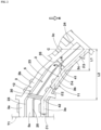
- FIG. 1 is a development view of a tread portion 2 of a tire (hereinafter, may be simply referred to as "tire") 1 of the present embodiment.
- tire 1 of the present embodiment is a tire for a passenger car, and is an all-season tire designed for running on a snow road in addition to running on a dry road surface.
- the tire 1 of the present invention is not limited to such a mode, and may be, for example, a heavy duty tire.
- the tire 1 of the present invention includes the tread portion 2 having a designated rotation direction R.
- the rotation direction R is indicated, for example, on a sidewall portion (now shown) by characters or marks.
- the tread portion 2 of the tire 1 of the present embodiment includes a first tread end T1 and a second tread end T2.
- a tread end on the left side of a tire equator C is defined as the first tread end T1
- a tread end on the right side of the tire equator C is defined as the second tread end T2.
- the tread portion 2 includes a first tread portion 2A on the first tread end T1 side with respect to the tire equator C and a second tread portion 2B on the second tread end T2 side with respect to the tire equator C.
- the first tread portion 2A and the second tread portion 2B are substantially line-symmetric with respect to the tire equator C except that the first tread portion 2A and the second tread portion 2B are displaced in the tire circumferential direction.
- each configuration of the first tread portion 2A can be applied to the second tread portion 2B.
- the first tread end T1 and the second tread end T2 are outermost ground-contact positions in the tire axial direction when 70% of a standardized load is applied to the tire 1 in a standardized state and the tire 1 is brought into contact with a flat surface at a camber angle of 0°.
- the "standardized state” is a state where the tire is fitted on a standardized rim and inflated to a standardized internal pressure and no load is applied to the tire.
- the standardized state means a standard use state, corresponding to the purpose of use of the tire, where no load is applied to the tire.
- dimensions and the like of components of the tire are values measured in the standardized state.
- a known method can be used as appropriate as a method for measuring the above dimensions.
- the "standardized rim” is a rim that is defined, in a standard system including a standard on which the tire is based, by the standard for each tire, and is, for example, the "standard rim” in the JATMA standard, the "Design Rim” in the TRA standard, or the “Measuring Rim” in the ETRTO standard.
- the "standardized internal pressure” is an air pressure that is defined, in a standard system including a standard on which the tire is based, by the standard for each tire, and is the “maximum air pressure” in the JATMA standard, the maximum value indicated in the table "TIRE LOAD LIMITS AT VARIOUS COLD INFLATION PRESSURES" in the TRA standard, or the “INFLATION PRESSURE” in the ETRTO standard.
- the "standardized load” is a load that is defined, in a standard system including a standard on which the tire is based, by the standard for each tire, and is the "maximum load capacity" in the JATMA standard, the maximum value indicated in the table "TIRE LOAD LIMITS AT VARIOUS COLD INFLATION PRESSURES" in the TRA standard, or the "LOAD CAPACITY” in the ETRTO standard.
- the "standardized load” refers to the maximum load applicable when the tire is used, according to the above-described standards.
- the tread portion 2 includes a plurality of first inclined grooves 3 and a plurality of second inclined grooves 4. In FIG. 1 , these grooves and longitudinal through grooves 30 described below are dotted.
- Each first inclined groove 3 extends at least from the first tread end T1 toward the tire equator C so as to be inclined toward a leading edge side in the rotation direction R.
- Each second inclined groove 4 extends at least from the second tread end T2 toward the tire equator C so as to be inclined toward the leading edge side in the rotation direction R.
- the second inclined groove 4 has substantially the same configuration as the first inclined groove 3, and the configuration of the first inclined groove 3 can be applied to the second inclined groove 4.
- a groove width W1 of the first inclined groove 3 and a groove width W2 of the second inclined groove 4 are, for example, not less than 3 mm, preferably 4.0 to 7.0 mm, and more preferably 4.5 to 6.0 mm.
- the depths of these inclined grooves are, for example, 4.0 to 8.5 mm and preferably 5.0 to 8.0 mm.
- Each first inclined groove 3 of the present embodiment extends from a position (not shown in FIG. 1 ) on the outer side in the tire axial direction with respect to the first tread end T1.
- the first inclined groove 3 crosses the center position in the tire axial direction between the first tread end T1 and the tire equator C and extends to the vicinity of the tire equator C.
- This configuration means that a distance in the tire axial direction from an inner end on the tire equator C side of each first inclined groove 3 to the tire equator C is not greater than 15% of a tread width TW.
- the distance from the inner end of the first inclined groove 3 to the tire equator C is not greater than 10% of the tread width TW.
- the tread width TW corresponds to a distance in the tire axial direction from the first tread end T1 to the second tread end T2 in the standardized state.
- the first inclined grooves 3 of the present embodiment include, for example, transverse first inclined grooves 3A extending to a position located beyond the tire equator C, and non-transverse first inclined grooves 3B terminating without crossing the tire equator C.
- the transverse first inclined grooves 3A and the non-transverse first inclined grooves 3B are provided alternately in the tire circumferential direction.
- the present invention is not limited to such a mode.
- the tread portion 2 of the present invention includes a plurality of first land portions 5 demarcated by the plurality of first inclined grooves 3.
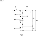
- FIG. 2 is an enlarged view of two first inclined grooves 3 and one first land portion 5.
- at least one through sipe 35 is provided on at least one of the plurality of first land portions 5 so as to penetrate the first land portion 5 in the tire circumferential direction.
- penetrate in the tire circumferential direction means that the through sipe 35 communicates with both the two first inclined grooves 3 between which the first land portion 5 is interposed.
- the through sipe 35 may be inclined relative to the tire circumferential direction.
- the "sipe” refers to a recess having a longitudinal direction and including a region in which two inner walls contact with each other in a state where the standardized load is applied to a ground-contact surface.
- the sipe width (an interval between the two inner walls in the standardized state) in the region is, for example, less than 1.5 mm and preferably 0.4 to 1.2 mm.
- the sipe may partly include a region in which the two inner walls do not contact with each other in the state where the standardized load is applied thereto.
- the sipe may include a widened portion or a chamfered portion described below.
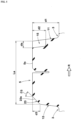
- FIG. 3 is a cross-sectional view taken along a line A-A in FIG. 2 .
- the through sipe 35 includes a sipe body 36 extending inward in the tire radial direction from a tread surface 5s of the first land portion 5, and a widened portion 37 connected to the inner side in the tire radial direction of the sipe body 36 and having a greater width than the sipe body 36.
- the tire 1 of the present invention can have improved wet braking performance while maintaining drainage performance in a tread width direction. The reason for this is as follows.
- the tire 1 of the present invention includes the plurality of first inclined grooves 3 as shown in FIG. 1 , excellent drainage performance can be exhibited in the tread width direction.
- the through sipe 35 including the widened portion 37 as shown in FIG. 3 can improve drainage performance in the tire circumferential direction and thus can improve wet braking performance while maintaining the stiffness of the tread portion 2 (shown in FIG. 1 ).
- the through sipe 35 including the widened portion 37 can maintain water absorptive performance even if the tread portion 2 is worn to some extent, and can exhibit excellent wet braking performance until the widened portion 37 appears at the ground-contact surface.
- the inner ends on the tire equator C side of the first inclined grooves 3 communicate with the second inclined grooves 4.
- a pair of the transverse first inclined groove 3A and the non-transverse first inclined groove 3B adjacent to each other in the tire circumferential direction communicate with the same second inclined groove 4.
- the second inclined grooves 4 communicate with the first inclined grooves 3 in the same manner. Accordingly, drainage performance in the vicinity of the tire equator C is improved and excellent wet braking performance is exhibited.
- each first inclined groove 3 includes an inner groove portion 3c on the tire equator C side, an outer groove portion 3a on the first tread end T1 side, and a center groove portion 3b connected to the inner groove portion 3c and the outer groove portion 3a.
- the inner groove portion 3c, the outer groove portion 3a, and the center groove portion 3b linearly extend, and angles thereof relative to the tire circumferential direction are different from each other.
- the angle of the first inclined groove 3 relative to the tire axial direction is increased toward the tire equator C side.
- Such a first inclined groove 3 provides frictional force in multiple directions and can further enhance wet performance.
- the outer groove portion 3a extends inward in the tire axial direction at least from the first tread end T1.
- An angle ⁇ 1 of the outer groove portion 3a relative to the tire axial direction is, for example, not greater than 10°.
- the outer groove portion 3a of the present embodiment extends so as to be parallel to the tire axial direction.
- An angle ⁇ 2 of the center groove portion 3b relative to the tire axial direction is greater than the angle ⁇ 1 of the outer groove portion 3a relative to the tire axial direction.
- the angle ⁇ 2 of the center groove portion 3b is, for example, 25 to 35°.
- An angle ⁇ 3 of the inner groove portion 3c relative to the tire axial direction is greater than the angle ⁇ 2 of the center groove portion 3b relative to the tire axial direction.
- the angle ⁇ 3 of the inner groove portion 3c is, for example, 40 to 50°.
- a distance L1 in the tire axial direction from the tire equator C to a junction 41 of the inner groove portion 3c and the center groove portion 3b is 10% to 25% of the tread width TW (shown in FIG. 1 ).
- the junction 41 refers to a position where an angle of the line tangent to the groove center line of the first inclined groove 3 indicates an intermediate value between an angle of the inner groove portion 3c and an angle of the center groove portion 3b.
- a distance L2 in the tire axial direction from the tire equator C to a junction 42 of the center groove portion 3b and the outer groove portion 3a is 30% to 45% of the tread width TW (shown in FIG. 1 ).
- the junction 42 refers to a position where an angle of the line tangent to the groove center line of the first inclined groove 3 indicates an intermediate value between the angle of the center groove portion 3b and an angle of the outer groove portion 3a.
- the first land portions 5 provided with the through sipes 35 and the first land portions 5 provided with no through sipe 35 are alternately arranged in the tire circumferential direction.
- the present invention is not limited to such a mode, and the through sipe 35 may be provided on each first land portion 5.
- each through sipe 35 is disposed on the tire equator C side with respect to the center position between the first tread end T1 and the tire equator C in the tire axial direction, for example.
- at least one end of the through sipe 35 communicates with the inner groove portion 3c of the first inclined groove 3.
- both ends of the through sipe 35 communicate with the inner groove portions 3c.
- the through sipe 35 is not disposed on the tire equator C. Accordingly, a distance between the through sipe 35 and the tire equator C is appropriate, so that wet performance and wear resistance are improved in a well-balanced manner.
- the through sipe 35 linearly extends in a tread plan view.
- the through sipe 35 is, for example, disposed so as to be inclined at an angle of 30 to 50° relative to the tire circumferential direction. Accordingly, an angle ⁇ 4 between the through sipe 35 and the first inclined groove 3 communicating with the leading edge side in the rotation direction R of the through sipe 35 is 75 to 105°.
- Such a through sipe 35 provides frictional force in the tire axial direction and the tire circumferential direction in a well-balanced manner.
- each through sipe 35 is located so as to face an inner end on the tire equator C side of each second inclined groove 4.
- the end portion of the through sipe 35 overlaps with a region obtained by virtually extending the second inclined groove 4 in a length direction thereof.
- the entire through sipe 35 overlaps with the virtually extended region in a tread plan view. Accordingly, the second inclined groove 4 and the through sipe 35 can cooperate to enhance drainage performance, so that wet braking performance is further improved.
- the sipe body 36 of the through sipe 35 linearly extends from the tread surface 5s of the first land portion 5 without a chamfered portion or the like therebetween so as to be parallel to the tire radial direction.
- a total depth d5 of the through sipe 35 is 60% to 95% of the maximum depth of the first inclined groove 3.
- a length L3 in the tire radial direction of the sipe body 36 is 50% to 80% of the maximum depth of the first inclined groove 3.
- a width W3 of the sipe body 36 is 0.4 to 0.8 mm.
- Such a sipe body 36 can enhance wet braking performance while maintaining the stiffness of the first land portion 5.
- the widened portion 37 forms a bottom portion of the through sipe 35.
- the widened portion 37 has a substantially semicircular contour on the inner side with respect to a portion communicating with the sipe body 36.
- the widened portion 37 extends in a longitudinal direction of the through sipe 35 while maintaining the contour.
- a length L4 in the tire radial direction of the widened portion 37 is 10% to 25% of the maximum depth of the first inclined groove 3.
- a maximum width W4 of the widened portion 37 is 2.5 to 4.0 times the width W3 of the sipe body 36.
- FIG. 4 is an enlarged view of the first land portion 5.
- FIG. 5 is a cross-sectional view taken along a line B-B in FIG. 4 .
- each first land portion 5 includes the tread surface 5s, a first side wall 11 on the leading edge side in the rotation direction R, and a second side wall 12 on a trailing edge side in the rotation direction R.
- At least one of the plurality of first land portions 5 is provided with at least one recess 15 formed by locally recessing the first side wall 11.
- the recess 15 is open at the tread surface 5s. With such a recess 15, a hard snow column can be formed when the first land portion 5 is brought into contact with the ground. In addition, excellent snow traction is exhibited when the snow column is sheared.
- a maximum recessed amount da of the recess 15 in a direction orthogonal to a longitudinal direction of the first inclined groove 3 is preferably 80% to 150% of the width W4 (shown in FIG. 3 ) of the widened portion 37 of the through sipe 35.
- the maximum recessed amount da is, for example, 1.0 to 2.5 mm and preferably 1.5 to 2.0 mm. Accordingly, wear progresses evenly in a portion around the recess 15 and a portion around the through sipe 35, so that uneven wear resistance is improved.
- the first land portion 5 is preferably provided with a plurality of the recesses 15.
- the maximum recessed amount da of each of the plurality of recesses 15 provided in the one first land portion 5 is set so as to be in the above-described range. Accordingly, the above-described effect can be assuredly exhibited.
- the plurality of recesses 15 provided in one first land portion 5 include a first recess 16, a second recess 17, and a third recess 18.
- the first recess 16 is provided closest to the first tread end T1 side among the plurality of recesses 15, and is in contact with the outer groove portion 3a (shown in FIG. 2 ) of the first inclined groove 3 in the present embodiment.
- the second recess 17 is located on the tire equator C side with respect to the first recess 16.
- the third recess 18 is located on the tire equator C side with respect to the second recess 17.
- the second recess 17 and the third recess 18 are in contact with the center groove portion 3b (shown in FIG. 2 ) of the first inclined groove 3.
- the first recess 16 is preferably away from the first tread end T1 and a longitudinal through groove 30 described below by 5.0 mm or more, for example.
- the second recess 17 is preferably away from the longitudinal through groove 30 by 5.0 mm or more.
- the third recess 18 is preferably away from the second recess 17 by 5.0 mm or more. Accordingly, uneven wear of the first land portion 5 is suppressed.
- the maximum length in the longitudinal direction of the recess 15 provided closest to the first tread end T1 (in the present embodiment, the first recess 16) among the plurality of recesses 15 provided on one first land portion 5 is larger than the maximum length in the longitudinal direction of the other recess 15 (in the present embodiment, the second recess 17 and the third recess 18).
- a maximum length L5 of the first recess 16 is 150% to 250% of a maximum length L6 of the second recess 17.
- the maximum length L6 of the second recess 17 is 80% to 120% of a maximum length L7 of the third recess 18, and in the present embodiment, these lengths are equal to each other.
- Such a plurality of the recesses 15 serve to enhance steering stability and on-snow performance in a well-balanced manner.
- the maximum length L5 of the first recess 16 is, for example, 3.0 to 12.0 mm and preferably 5.0 to 10.0 mm.
- the maximum length L6 of the second recess 17 and the maximum length L7 of the third recess 18 are, for example, 3.0 to 8.0 mm and preferably 4.0 to 7.0 mm.
- the opening shape of the recess 15 in the tread surface 5s of the first land portion 5 is, for example, trapezoidal. However, the present invention is not limited to such a shape, and the opening shape may be triangular or semicircular.
- a maximum depth d2 of the recess 15 from the tread surface 5s is 50% to 80% of a maximum depth d1 of the first inclined groove 3.
- the first land portion 5 includes a chamfered portion 23 formed at least partially between the second side wall 12 and the tread surface 5s.
- the chamfered portion 23 is formed as a minute inclined surface 23s disposed such that a ridge angle formed by the second side wall 12 and the tread surface 5s is eliminated.
- strain of the tread surface during braking on a dry road surface is suppressed, and a substantial ground-contact area is increased, so that braking performance on a dry road surface is improved.
- An angle ⁇ 5 of the inclined surface 23s of the chamfered portion 23 relative to a line normal to the tire is, for example, 30 to 60° and preferably 40 to 50°.
- a width W5 (shown in FIG. 4 ) of the inclined surface 23s in the plan view of the first land portion 5 is, for example, 0.5 to 2.0 mm and preferably 1.0 to 1.5 mm.
- a depth d3 of the inclined surface 23s is, for example, 0.5 to 2.5 mm and preferably 1.0 to 2.0 mm.
- the above-described chamfered portion 23 is formed in portions, of the first land portion 5, which are in contact with the outer groove portion 3a and the center groove portion 3b of the first inclined groove 3. Accordingly, the chamfered portion 23 is disposed in a region where the ground-contact pressure increases during braking, so that the above-described effect is assuredly achieved.
- the area of the chamfered portion 23 is 10% to 15% of the area of the tread surface 5s of one first land portion 5. Accordingly, steering stability and on-snow performance are improved in a well-balanced manner.
- the second side wall 12 includes a non-chamfered portion 24 connected to the tread surface 5s without the chamfered portion 23 therebetween.
- the non-chamfered portion 24 is disposed in a portion, of the second side wall 12, in contact with the inner groove portion 3c. Accordingly, since the non-chamfered portion 24 is disposed in a region close to the tire equator C, a high edge effect can be expected. Thus, excellent snow traction can be expected.
- At least one inclined sipe 25 is provided on the first land portion 5 so as to extend along the longitudinal direction of the first inclined groove 3 (shown in FIG. 2 ).
- one inclined sipe 25 is provided on one first land portion 5.
- the inclined sipe 25 extends along the first inclined groove 3 (shown in FIG. 2 ) from the first tread end T1 to an end portion on the tire equator C side of the first land portion 5.
- the inclined sipe 25 is provided in a central region among three equal regions into which the first land portion 5 is divided in the direction orthogonal to the longitudinal direction of the first inclined groove 3 by two virtual lines extending along the longitudinal direction of the first inclined groove 3.
- Such an inclined sipe 25 can enhance wet performance while suppressing uneven wear of the first land portion 5.
- the inclined sipe 25 includes an outer sipe portion 25a, a central sipe portion 25b, and an inner sipe portion 25c.
- the outer sipe portion 25a linearly extends inward in the tire axial direction at least from the first tread end T1.
- the outer sipe portion 25a of the present embodiment extends along the outer groove portion 3a (shown in FIG. 2 ) of the first inclined groove 3, and in a preferable mode, these portions are parallel to each other.
- the length of the outer sipe portion 25a is 80% to 120% of the length of the outer groove portion 3a.
- the central sipe portion 25b is connected to the inner side in the tire axial direction of the outer sipe portion 25a and linearly extends.
- the central sipe portion 25b extends along the center groove portion 3b (shown in FIG. 2 ) of the first inclined groove 3, and in a preferable mode, these portions are parallel to each other.
- the length of the central sipe portion 25b is 80% to 120% of the length of the center groove portion 3b.
- the inner sipe portion 25c is connected to the inner side in the tire axial direction of the central sipe portion 25b and linearly extends.
- the inner sipe portion 25c extends along the inner groove portion 3c (shown in FIG. 2 ) of the first inclined groove 3, and in a preferable mode, these portions are parallel to each other.
- the length of the inner sipe portion 25c is 80% to 120% of the length of the inner groove portion 3c.
- FIG. 6 is a cross-sectional view taken along a line C-C in FIG. 4 .
- the inclined sipe 25 has a chamfered portion 28 provided at an edge thereof on the leading edge side in the rotation direction R.
- the chamfered portion 28 is formed as a minute inclined surface disposed such that a ridge angle formed by a sipe wall 25w and the tread surface 5s of the first land portion 5 is eliminated.
- An angle of this inclined surface relative to a line normal to the tire is, for example, 40 to 50°.
- Such a chamfered portion 28 can enhance braking performance on a dry road surface.
- the inclined sipe 25 has no chamfered portion at an edge thereof on the trailing edge side in the rotation direction R. Accordingly, the edge on the trailing edge side of the inclined sipe 25 can exert a large frictional force during running on snow, so that snow traction is improved.
- the above-described chamfered portion 28 is provided at the outer sipe portion 25a and the central sipe portion 25b.
- no chamfered portion is provided at the edges on both sides of the inner sipe portion 25c. Accordingly, steering stability on a dry road surface and snow traction are improved in a well-balanced manner.
- At least one longitudinal through groove 30 is provided on the first land portion 5 of the present embodiment so as to connect the two first inclined grooves 3 adjacent to each other in the tire circumferential direction.
- one longitudinal through groove 30 is provided on one first land portion 5.
- the longitudinal through groove 30 of the present embodiment connects the center groove portions 3b of the first inclined grooves 3 adjacent to each other in the tire circumferential direction.
- the positions at which the longitudinal through groove 30 communicates with the center groove portions 3b are on the first tread end T1 side with respect to the center positions in the longitudinal direction of the center groove portions 3b.
- Such a longitudinal through groove 30 makes it easier for a portion therearound to deform moderately, and can inhibit snow from clogging the first inclined groove 3. Accordingly, excellent on-snow performance is continuously exhibited.
- the longitudinal through groove 30 is inclined in a direction opposite to that of the center groove portion 3b with respect to the tire axial direction.
- An angle of the longitudinal through groove 30 relative to the tire circumferential direction is, for example, 5 to 15°.
- Such a longitudinal through groove 30 can exert a large snow column shearing force in the tire axial direction during running on snow.
- FIG. 7 is a cross-sectional view taken along a line D-D in FIG. 4 .
- the longitudinal through groove 30 has a bottom surface with an opening in which a groove bottom narrow groove 31 extending in the tire radial direction is formed.
- a groove bottom narrow groove 31 serves to further improve wet performance.
- the land ratio of the tread portion 2 of the present embodiment is, for example, 50% to 65% and preferably 55% to 60%. Accordingly, steering stability and snow traction are improved in a well-balanced manner.
- "land ratio” corresponds to the ratio of an actual ground-contact area to a ground-contact area in a state where all the grooves and the sipes of the tread portion 2 are filled.
- FIG. 8 is a development view of a tread portion 2 of a tire 1 according to another embodiment of the present invention.
- one crown circumferential groove 7 continuously and linearly extending in the tire circumferential direction is provided on the tire equator C.
- each of the first inclined grooves 3 and the second inclined grooves 4 communicates with the crown circumferential groove 7.
- the crown circumferential groove 7 enhances drainage performance in the tire circumferential direction, so that wet braking performance is further improved.
- the embodiment shown in FIG. 8 is substantially the same as the embodiment shown in FIG. 1 except for the above crown circumferential groove 7, and has the above-described configuration.
- FIG. 9 is a development view of a tread portion 2 of a tire 1 according to another embodiment of the present invention.
- each first land portion 5 has a first corner 5a
- the first corner 5a has a chamfered portion 45.
- the first corner 5a is a corner formed where the first inclined groove 3 is connected to the second inclined groove 4, and is a corner projecting toward one side in the tire circumferential direction (in this embodiment, the leading edge side in the rotation direction R).
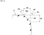
- FIG. 10 is an enlarged sectional view of the first corner 5a having the chamfered portion 45.
- the chamfered portion 45 of the first corner 5a has an inclined surface 46 inclined at an angle ⁇ 6 of 30 to 50° relative to a line normal to the tire.
- the inclined surface 46 is bought into contact with the ground during braking, so that a substantial ground-contact area is increased.
- braking performance on a dry road surface and a wet road surface can be enhanced.
- the maximum width W5 in the tire axial direction of the chamfered portion 45 is, for example, 3 to 5 mm.
- the angle, relative to the tire circumferential direction, of a ridge 45a formed by the tread surface 5s of the first land portion 5 and the inclined surface 46 of the chamfered portion 45 (shown in FIG. 10 ) is, for example, 80 to 90°.
- a length L8 in the tire circumferential direction of the inclined surface 46 of the chamfered portion 45 is 3 to 5 mm.
- a length L9 in the tire radial direction of the inclined surface 46 of the chamfered portion 45 is not greater than 50% of the maximum depth d1 of the first inclined groove 3.
- a second corner 5b of each first land portion 5 of this embodiment does not have the above-described chamfered portion.
- the second corner 5b is a corner formed where the first inclined groove 3 is connected to the second inclined groove 4, and is a corner projecting toward the second tread end T2 side. Accordingly, the second corner 5b can provide a large frictional force in the tire axial direction, so that excellent cornering performance can be exhibited on a dry road surface and a wet road surface.
- FIG. 11 is a development view of a tread portion 2 of a tire 1 according to another embodiment of the present invention.
- the above-described chamfered portion 45 is added to each first land portion 5 of the tire 1 shown in FIG. 8 . Also, in this embodiment, the above-described effect can be obtained with the chamfered portion 45.
- a pneumatic tire with a size of 205/55R16 having the basic pattern in FIG. 1 was produced as a test tire.
- a tire including the through sipes that were each composed of only the sipe body extending with a uniform width and have no widened portion was produced as a test tire.
- These test tires have substantially the same configuration except for the above-described matters.
- Each test tire was tested (when the tire was new and when the tire was 20% worn) for drainage performance on a wet road surface and wet braking performance.
- the common specifications and the test methods for the test tires are as follows.
- the test vehicle was caused to run on a wet road surface, and the speed at which a hydroplaning phenomenon occurred was measured. Regarding the result, the speed is indicated as an index. A higher value indicates that drainage performance on a wet road surface is better.
- the test vehicle was caused to rapidly brake on a wet road surface, and the braking distance was measured. Regarding the result, the reciprocal of the braking distance is indicated as an index. A higher value indicates that wet braking performance is better.
- the tire of the example has improved drainage performance on a wet road surface and wet braking performance compared to the tire of the comparative example, by three points.
- the tire of the example can maintain drainage performance on a wet road surface and wet braking performance even when the tread portion is 20% worn.
- the present invention includes the following aspects.
- a tire including a tread portion having a designated rotation direction, wherein
Landscapes
- Engineering & Computer Science (AREA)
- Mechanical Engineering (AREA)
- Tires In General (AREA)
Abstract
Description
- The present invention relates to a tire.
-
Japanese Laid-Open Patent Publication No. 2019-156025 - In the tire as in
Japanese Laid-Open Patent Publication No. 2019-156025 - The present invention has been made in view of the above circumstances, and a main object of the present invention is to provide a tire capable of improving wet braking performance while maintaining drainage performance in a tread width direction.
- The present invention is directed to a tire that includes a tread portion having a designated rotation direction, wherein the tread portion includes a first tread end, a plurality of first inclined grooves extending at least from the first tread end to a portion around a tire equator so as to be inclined toward a leading edge side in the rotation direction, and a plurality of first land portions demarcated by the plurality of first inclined grooves, at least one through sipe is provided on at least one of the plurality of first land portions so as to penetrate the first land portion in a tire circumferential direction, and the through sipe includes a sipe body extending inward in a tire radial direction from a tread surface of the first land portion and a widened portion connected to an inner side in the tire radial direction of the sipe body and having a greater width than the sipe body.
- As a result of adopting the above-described configuration, the tire according to the present invention can have improved wet braking performance while maintaining drainage performance in a tread width direction.
-
-
FIG. 1 is a development view of a tread portion of a tire according to one embodiment of the present invention; -
FIG. 2 is an enlarged view of a first land portion and first inclined grooves inFIG. 1 ; -
FIG. 3 is a cross-sectional view taken along a line A-A inFIG. 2 ; -
FIG. 4 is an enlarged view of the first land portion inFIG. 1 ; -
FIG. 5 is a cross-sectional view taken along a line B-B inFIG. 4 ; -
FIG. 6 is a cross-sectional view taken along a line C-C inFIG. 4 ; -
FIG. 7 is a cross-sectional view taken along a line D-D inFIG. 4 ; -
FIG. 8 is a development view of a tread portion of a tire according to another embodiment of the present invention; -
FIG. 9 is a development view of a tread portion of a tire according to another embodiment of the present invention; -
FIG. 10 is an enlarged sectional view of a chamfered portion inFIG. 9 ; and -
FIG. 11 is a development view of a tread portion of a tire according to another embodiment of the present invention. - Hereinafter, embodiments of the present invention will be described with reference to the drawings. The drawings are depicted so as to include the features of the present invention, but may contain exaggerated expressions and expressions that differ from the dimensional ratio of the actual structure in order to help the understanding of the present invention. In addition, the same or common elements are denoted by the same reference characters throughout each embodiment, and the redundant description thereof is omitted.
FIG. 1 is a development view of atread portion 2 of a tire (hereinafter, may be simply referred to as "tire") 1 of the present embodiment. As shown inFIG. 1 , the tire 1 of the present embodiment is a tire for a passenger car, and is an all-season tire designed for running on a snow road in addition to running on a dry road surface. However, the tire 1 of the present invention is not limited to such a mode, and may be, for example, a heavy duty tire. - The tire 1 of the present invention includes the
tread portion 2 having a designated rotation direction R. The rotation direction R is indicated, for example, on a sidewall portion (now shown) by characters or marks. - The
tread portion 2 of the tire 1 of the present embodiment includes a first tread end T1 and a second tread end T2. In each drawing of the present specification, a tread end on the left side of a tire equator C is defined as the first tread end T1, and a tread end on the right side of the tire equator C is defined as the second tread end T2. Thetread portion 2 includes afirst tread portion 2A on the first tread end T1 side with respect to the tire equator C and asecond tread portion 2B on the second tread end T2 side with respect to the tire equator C. Thefirst tread portion 2A and thesecond tread portion 2B are substantially line-symmetric with respect to the tire equator C except that thefirst tread portion 2A and thesecond tread portion 2B are displaced in the tire circumferential direction. Thus, each configuration of thefirst tread portion 2A can be applied to thesecond tread portion 2B. - The first tread end T1 and the second tread end T2 are outermost ground-contact positions in the tire axial direction when 70% of a standardized load is applied to the tire 1 in a standardized state and the tire 1 is brought into contact with a flat surface at a camber angle of 0°.
- In the case of a pneumatic tire for which various standards are defined, the "standardized state" is a state where the tire is fitted on a standardized rim and inflated to a standardized internal pressure and no load is applied to the tire. In the case of a non-pneumatic tire or a tire for which various standards are not defined, the standardized state means a standard use state, corresponding to the purpose of use of the tire, where no load is applied to the tire. In the present specification, unless otherwise specified, dimensions and the like of components of the tire are values measured in the standardized state. In the present specification, unless otherwise specified, a known method can be used as appropriate as a method for measuring the above dimensions.
- The "standardized rim" is a rim that is defined, in a standard system including a standard on which the tire is based, by the standard for each tire, and is, for example, the "standard rim" in the JATMA standard, the "Design Rim" in the TRA standard, or the "Measuring Rim" in the ETRTO standard.
- The "standardized internal pressure" is an air pressure that is defined, in a standard system including a standard on which the tire is based, by the standard for each tire, and is the "maximum air pressure" in the JATMA standard, the maximum value indicated in the table "TIRE LOAD LIMITS AT VARIOUS COLD INFLATION PRESSURES" in the TRA standard, or the "INFLATION PRESSURE" in the ETRTO standard.
- In the case of a pneumatic tire for which various standards are defined, the "standardized load" is a load that is defined, in a standard system including a standard on which the tire is based, by the standard for each tire, and is the "maximum load capacity" in the JATMA standard, the maximum value indicated in the table "TIRE LOAD LIMITS AT VARIOUS COLD INFLATION PRESSURES" in the TRA standard, or the "LOAD CAPACITY" in the ETRTO standard. In the case of a tire for which various standards are not defined, the "standardized load" refers to the maximum load applicable when the tire is used, according to the above-described standards.
- The
tread portion 2 includes a plurality of firstinclined grooves 3 and a plurality of secondinclined grooves 4. InFIG. 1 , these grooves and longitudinal throughgrooves 30 described below are dotted. Each firstinclined groove 3 extends at least from the first tread end T1 toward the tire equator C so as to be inclined toward a leading edge side in the rotation direction R. Each secondinclined groove 4 extends at least from the second tread end T2 toward the tire equator C so as to be inclined toward the leading edge side in the rotation direction R. The secondinclined groove 4 has substantially the same configuration as the firstinclined groove 3, and the configuration of the firstinclined groove 3 can be applied to the secondinclined groove 4. - From the viewpoint of ensuring wet performance, a groove width W1 of the first
inclined groove 3 and a groove width W2 of the secondinclined groove 4 are, for example, not less than 3 mm, preferably 4.0 to 7.0 mm, and more preferably 4.5 to 6.0 mm. In addition, the depths of these inclined grooves are, for example, 4.0 to 8.5 mm and preferably 5.0 to 8.0 mm. - Each first
inclined groove 3 of the present embodiment extends from a position (not shown inFIG. 1 ) on the outer side in the tire axial direction with respect to the first tread end T1. In addition, the firstinclined groove 3 crosses the center position in the tire axial direction between the first tread end T1 and the tire equator C and extends to the vicinity of the tire equator C. This configuration means that a distance in the tire axial direction from an inner end on the tire equator C side of each firstinclined groove 3 to the tire equator C is not greater than 15% of a tread width TW. In a preferable mode, the distance from the inner end of the firstinclined groove 3 to the tire equator C is not greater than 10% of the tread width TW. The tread width TW corresponds to a distance in the tire axial direction from the first tread end T1 to the second tread end T2 in the standardized state. - The first
inclined grooves 3 of the present embodiment include, for example, transverse firstinclined grooves 3A extending to a position located beyond the tire equator C, and non-transverse firstinclined grooves 3B terminating without crossing the tire equator C. In the present embodiment, the transverse firstinclined grooves 3A and the non-transverse firstinclined grooves 3B are provided alternately in the tire circumferential direction. However, the present invention is not limited to such a mode. - The
tread portion 2 of the present invention includes a plurality offirst land portions 5 demarcated by the plurality of firstinclined grooves 3.FIG. 2 is an enlarged view of two firstinclined grooves 3 and onefirst land portion 5. As shown inFIG. 1 andFIG. 2 , at least one throughsipe 35 is provided on at least one of the plurality offirst land portions 5 so as to penetrate thefirst land portion 5 in the tire circumferential direction. Here, "penetrate in the tire circumferential direction" means that the throughsipe 35 communicates with both the two firstinclined grooves 3 between which thefirst land portion 5 is interposed. Thus, thethrough sipe 35 may be inclined relative to the tire circumferential direction. - In the present specification, the "sipe" refers to a recess having a longitudinal direction and including a region in which two inner walls contact with each other in a state where the standardized load is applied to a ground-contact surface. The sipe width (an interval between the two inner walls in the standardized state) in the region is, for example, less than 1.5 mm and preferably 0.4 to 1.2 mm. The sipe may partly include a region in which the two inner walls do not contact with each other in the state where the standardized load is applied thereto. Thus, the sipe may include a widened portion or a chamfered portion described below.
-
FIG. 3 is a cross-sectional view taken along a line A-A inFIG. 2 . As shown inFIG. 3 , the throughsipe 35 includes asipe body 36 extending inward in the tire radial direction from atread surface 5s of thefirst land portion 5, and a widenedportion 37 connected to the inner side in the tire radial direction of thesipe body 36 and having a greater width than thesipe body 36. As a result of adopting the above-described configuration, the tire 1 of the present invention can have improved wet braking performance while maintaining drainage performance in a tread width direction. The reason for this is as follows. - Since the tire 1 of the present invention includes the plurality of first
inclined grooves 3 as shown inFIG. 1 , excellent drainage performance can be exhibited in the tread width direction. In addition, the throughsipe 35 including the widenedportion 37 as shown inFIG. 3 can improve drainage performance in the tire circumferential direction and thus can improve wet braking performance while maintaining the stiffness of the tread portion 2 (shown inFIG. 1 ). Furthermore, the throughsipe 35 including the widenedportion 37 can maintain water absorptive performance even if thetread portion 2 is worn to some extent, and can exhibit excellent wet braking performance until the widenedportion 37 appears at the ground-contact surface. - Hereinafter, more detailed configurations of the present embodiment will be described. The configurations described below show a specific mode of the present embodiment. Therefore, it is needless to say that the present invention can achieve the above-described effect even when the configurations described below are not provided. In addition, even when any one of the configurations described below is independently applied to the tire 1 of the present invention having the above-described characteristics, performance improvement corresponding to each configuration can be expected. Furthermore, when some of the configurations described below are applied in combination, complex performance improvement corresponding to each configuration can be expected.
- As shown in
FIG. 1 , the inner ends on the tire equator C side of the firstinclined grooves 3 communicate with the secondinclined grooves 4. In a preferable mode, a pair of the transverse firstinclined groove 3A and the non-transverse firstinclined groove 3B adjacent to each other in the tire circumferential direction communicate with the same secondinclined groove 4. The secondinclined grooves 4 communicate with the firstinclined grooves 3 in the same manner. Accordingly, drainage performance in the vicinity of the tire equator C is improved and excellent wet braking performance is exhibited. - As shown in
FIG. 2 , each firstinclined groove 3 includes aninner groove portion 3c on the tire equator C side, anouter groove portion 3a on the first tread end T1 side, and acenter groove portion 3b connected to theinner groove portion 3c and theouter groove portion 3a. Theinner groove portion 3c, theouter groove portion 3a, and thecenter groove portion 3b linearly extend, and angles thereof relative to the tire circumferential direction are different from each other. In a preferable mode, the angle of the firstinclined groove 3 relative to the tire axial direction is increased toward the tire equator C side. Such a firstinclined groove 3 provides frictional force in multiple directions and can further enhance wet performance. - The
outer groove portion 3a extends inward in the tire axial direction at least from the first tread end T1. An angle θ1 of theouter groove portion 3a relative to the tire axial direction is, for example, not greater than 10°. Theouter groove portion 3a of the present embodiment extends so as to be parallel to the tire axial direction. - An angle θ2 of the
center groove portion 3b relative to the tire axial direction is greater than the angle θ1 of theouter groove portion 3a relative to the tire axial direction. The angle θ2 of thecenter groove portion 3b is, for example, 25 to 35°. An angle θ3 of theinner groove portion 3c relative to the tire axial direction is greater than the angle θ2 of thecenter groove portion 3b relative to the tire axial direction. The angle θ3 of theinner groove portion 3c is, for example, 40 to 50°. Such a firstinclined groove 3 including theouter groove portion 3a, thecenter groove portion 3b, and theinner groove portion 3c can exhibit excellent drainage performance in the tread width direction. - As shown in
FIG. 2 , a distance L1 in the tire axial direction from the tire equator C to ajunction 41 of theinner groove portion 3c and thecenter groove portion 3b is 10% to 25% of the tread width TW (shown inFIG. 1 ). Thejunction 41 refers to a position where an angle of the line tangent to the groove center line of the firstinclined groove 3 indicates an intermediate value between an angle of theinner groove portion 3c and an angle of thecenter groove portion 3b. - A distance L2 in the tire axial direction from the tire equator C to a
junction 42 of thecenter groove portion 3b and theouter groove portion 3a is 30% to 45% of the tread width TW (shown inFIG. 1 ). Thejunction 42 refers to a position where an angle of the line tangent to the groove center line of the firstinclined groove 3 indicates an intermediate value between the angle of thecenter groove portion 3b and an angle of theouter groove portion 3a. With such arrangement of the groove portions, wet performance and wear resistance are improved in a well-balanced manner. - As shown in
FIG. 1 , in the present embodiment, thefirst land portions 5 provided with the throughsipes 35 and thefirst land portions 5 provided with no throughsipe 35 are alternately arranged in the tire circumferential direction. However, the present invention is not limited to such a mode, and the throughsipe 35 may be provided on eachfirst land portion 5. - As shown in
FIG. 2 , each throughsipe 35 is disposed on the tire equator C side with respect to the center position between the first tread end T1 and the tire equator C in the tire axial direction, for example. In a preferable mode, at least one end of the throughsipe 35 communicates with theinner groove portion 3c of the firstinclined groove 3. In a more preferable mode, both ends of the throughsipe 35 communicate with theinner groove portions 3c. In addition, the throughsipe 35 is not disposed on the tire equator C. Accordingly, a distance between the throughsipe 35 and the tire equator C is appropriate, so that wet performance and wear resistance are improved in a well-balanced manner. - The through
sipe 35 linearly extends in a tread plan view. In addition, the throughsipe 35 is, for example, disposed so as to be inclined at an angle of 30 to 50° relative to the tire circumferential direction. Accordingly, an angle θ4 between the throughsipe 35 and the firstinclined groove 3 communicating with the leading edge side in the rotation direction R of the throughsipe 35 is 75 to 105°. Such a throughsipe 35 provides frictional force in the tire axial direction and the tire circumferential direction in a well-balanced manner. - As shown in
FIG. 1 , an end portion on the tire equator C side of each throughsipe 35 is located so as to face an inner end on the tire equator C side of each secondinclined groove 4. Specifically, in a tread plan view, the end portion of the throughsipe 35 overlaps with a region obtained by virtually extending the secondinclined groove 4 in a length direction thereof. In a more preferable mode, in the present embodiment, the entire throughsipe 35 overlaps with the virtually extended region in a tread plan view. Accordingly, the secondinclined groove 4 and the throughsipe 35 can cooperate to enhance drainage performance, so that wet braking performance is further improved. - As shown in
FIG. 3 , thesipe body 36 of the throughsipe 35 linearly extends from thetread surface 5s of thefirst land portion 5 without a chamfered portion or the like therebetween so as to be parallel to the tire radial direction. A total depth d5 of the throughsipe 35 is 60% to 95% of the maximum depth of the firstinclined groove 3. A length L3 in the tire radial direction of thesipe body 36 is 50% to 80% of the maximum depth of the firstinclined groove 3. In addition, a width W3 of thesipe body 36 is 0.4 to 0.8 mm. Such asipe body 36 can enhance wet braking performance while maintaining the stiffness of thefirst land portion 5. - The widened
portion 37 forms a bottom portion of the throughsipe 35. In addition, the widenedportion 37 has a substantially semicircular contour on the inner side with respect to a portion communicating with thesipe body 36. In addition, the widenedportion 37 extends in a longitudinal direction of the throughsipe 35 while maintaining the contour. A length L4 in the tire radial direction of the widenedportion 37 is 10% to 25% of the maximum depth of the firstinclined groove 3. A maximum width W4 of the widenedportion 37 is 2.5 to 4.0 times the width W3 of thesipe body 36. Such a widenedportion 37 can enhance wet braking performance while suppressing vulcanization molding defects. -
FIG. 4 is an enlarged view of thefirst land portion 5.FIG. 5 is a cross-sectional view taken along a line B-B inFIG. 4 . As shown inFIG. 4 andFIG. 5 , eachfirst land portion 5 includes thetread surface 5s, afirst side wall 11 on the leading edge side in the rotation direction R, and asecond side wall 12 on a trailing edge side in the rotation direction R. - At least one of the plurality of
first land portions 5 is provided with at least onerecess 15 formed by locally recessing thefirst side wall 11. Therecess 15 is open at thetread surface 5s. With such arecess 15, a hard snow column can be formed when thefirst land portion 5 is brought into contact with the ground. In addition, excellent snow traction is exhibited when the snow column is sheared. - As shown in
FIG. 5 , in a plan view of thefirst land portion 5, a maximum recessed amount da of therecess 15 in a direction orthogonal to a longitudinal direction of the firstinclined groove 3 is preferably 80% to 150% of the width W4 (shown inFIG. 3 ) of the widenedportion 37 of the throughsipe 35. In addition, the maximum recessed amount da is, for example, 1.0 to 2.5 mm and preferably 1.5 to 2.0 mm. Accordingly, wear progresses evenly in a portion around therecess 15 and a portion around the throughsipe 35, so that uneven wear resistance is improved. - As shown in
FIG. 4 , thefirst land portion 5 is preferably provided with a plurality of therecesses 15. In the present embodiment, the maximum recessed amount da of each of the plurality ofrecesses 15 provided in the onefirst land portion 5 is set so as to be in the above-described range. Accordingly, the above-described effect can be assuredly exhibited. - In the present embodiment, the plurality of
recesses 15 provided in onefirst land portion 5 include afirst recess 16, asecond recess 17, and athird recess 18. Thefirst recess 16 is provided closest to the first tread end T1 side among the plurality ofrecesses 15, and is in contact with theouter groove portion 3a (shown inFIG. 2 ) of the firstinclined groove 3 in the present embodiment. Thesecond recess 17 is located on the tire equator C side with respect to thefirst recess 16. Thethird recess 18 is located on the tire equator C side with respect to thesecond recess 17. Thesecond recess 17 and thethird recess 18 are in contact with thecenter groove portion 3b (shown inFIG. 2 ) of the firstinclined groove 3. - The
first recess 16 is preferably away from the first tread end T1 and a longitudinal throughgroove 30 described below by 5.0 mm or more, for example. Thesecond recess 17 is preferably away from the longitudinal throughgroove 30 by 5.0 mm or more. Thethird recess 18 is preferably away from thesecond recess 17 by 5.0 mm or more. Accordingly, uneven wear of thefirst land portion 5 is suppressed. - The maximum length in the longitudinal direction of the
recess 15 provided closest to the first tread end T1 (in the present embodiment, the first recess 16) among the plurality ofrecesses 15 provided on onefirst land portion 5 is larger than the maximum length in the longitudinal direction of the other recess 15 (in the present embodiment, thesecond recess 17 and the third recess 18). Specifically, a maximum length L5 of thefirst recess 16 is 150% to 250% of a maximum length L6 of thesecond recess 17. The maximum length L6 of thesecond recess 17 is 80% to 120% of a maximum length L7 of thethird recess 18, and in the present embodiment, these lengths are equal to each other. Such a plurality of therecesses 15 serve to enhance steering stability and on-snow performance in a well-balanced manner. - The maximum length L5 of the
first recess 16 is, for example, 3.0 to 12.0 mm and preferably 5.0 to 10.0 mm. The maximum length L6 of thesecond recess 17 and the maximum length L7 of thethird recess 18 are, for example, 3.0 to 8.0 mm and preferably 4.0 to 7.0 mm. - The opening shape of the
recess 15 in thetread surface 5s of thefirst land portion 5 is, for example, trapezoidal. However, the present invention is not limited to such a shape, and the opening shape may be triangular or semicircular. - From the same viewpoint, as shown in
FIG. 5 , a maximum depth d2 of therecess 15 from thetread surface 5s is 50% to 80% of a maximum depth d1 of the firstinclined groove 3. - The
first land portion 5 includes a chamferedportion 23 formed at least partially between thesecond side wall 12 and thetread surface 5s. The chamferedportion 23 is formed as a minuteinclined surface 23s disposed such that a ridge angle formed by thesecond side wall 12 and thetread surface 5s is eliminated. In the present embodiment, since such a chamferedportion 23 is formed on thesecond side wall 12 side, strain of the tread surface during braking on a dry road surface is suppressed, and a substantial ground-contact area is increased, so that braking performance on a dry road surface is improved. - An angle θ5 of the
inclined surface 23s of the chamferedportion 23 relative to a line normal to the tire is, for example, 30 to 60° and preferably 40 to 50°. A width W5 (shown inFIG. 4 ) of theinclined surface 23s in the plan view of thefirst land portion 5 is, for example, 0.5 to 2.0 mm and preferably 1.0 to 1.5 mm. A depth d3 of theinclined surface 23s is, for example, 0.5 to 2.5 mm and preferably 1.0 to 2.0 mm. - As shown in
FIG. 2 , in the present embodiment, the above-describedchamfered portion 23 is formed in portions, of thefirst land portion 5, which are in contact with theouter groove portion 3a and thecenter groove portion 3b of the firstinclined groove 3. Accordingly, the chamferedportion 23 is disposed in a region where the ground-contact pressure increases during braking, so that the above-described effect is assuredly achieved. - In a plan view of the
first land portion 5, the area of the chamferedportion 23 is 10% to 15% of the area of thetread surface 5s of onefirst land portion 5. Accordingly, steering stability and on-snow performance are improved in a well-balanced manner. - The
second side wall 12 includes anon-chamfered portion 24 connected to thetread surface 5s without the chamferedportion 23 therebetween. Thenon-chamfered portion 24 is disposed in a portion, of thesecond side wall 12, in contact with theinner groove portion 3c. Accordingly, since thenon-chamfered portion 24 is disposed in a region close to the tire equator C, a high edge effect can be expected. Thus, excellent snow traction can be expected. - As shown in
FIG. 4 , at least oneinclined sipe 25 is provided on thefirst land portion 5 so as to extend along the longitudinal direction of the first inclined groove 3 (shown inFIG. 2 ). In the present embodiment, one inclinedsipe 25 is provided on onefirst land portion 5. - The
inclined sipe 25 extends along the first inclined groove 3 (shown inFIG. 2 ) from the first tread end T1 to an end portion on the tire equator C side of thefirst land portion 5. In a preferable mode, theinclined sipe 25 is provided in a central region among three equal regions into which thefirst land portion 5 is divided in the direction orthogonal to the longitudinal direction of the firstinclined groove 3 by two virtual lines extending along the longitudinal direction of the firstinclined groove 3. Such aninclined sipe 25 can enhance wet performance while suppressing uneven wear of thefirst land portion 5. - The
inclined sipe 25 includes anouter sipe portion 25a, acentral sipe portion 25b, and aninner sipe portion 25c. Theouter sipe portion 25a linearly extends inward in the tire axial direction at least from the first tread end T1. Theouter sipe portion 25a of the present embodiment extends along theouter groove portion 3a (shown inFIG. 2 ) of the firstinclined groove 3, and in a preferable mode, these portions are parallel to each other. In addition, the length of theouter sipe portion 25a is 80% to 120% of the length of theouter groove portion 3a. - The
central sipe portion 25b is connected to the inner side in the tire axial direction of theouter sipe portion 25a and linearly extends. Thecentral sipe portion 25b extends along thecenter groove portion 3b (shown inFIG. 2 ) of the firstinclined groove 3, and in a preferable mode, these portions are parallel to each other. In addition, the length of thecentral sipe portion 25b is 80% to 120% of the length of thecenter groove portion 3b. - The
inner sipe portion 25c is connected to the inner side in the tire axial direction of thecentral sipe portion 25b and linearly extends. Theinner sipe portion 25c extends along theinner groove portion 3c (shown inFIG. 2 ) of the firstinclined groove 3, and in a preferable mode, these portions are parallel to each other. In addition, the length of theinner sipe portion 25c is 80% to 120% of the length of theinner groove portion 3c. Such aninclined sipe 25 including theouter sipe portion 25a, thecentral sipe portion 25b, and theinner sipe portion 25c can assuredly suppress uneven wear of thefirst land portion 5. -
FIG. 6 is a cross-sectional view taken along a line C-C inFIG. 4 . As shown inFIG. 6 , theinclined sipe 25 has a chamferedportion 28 provided at an edge thereof on the leading edge side in the rotation direction R. The chamferedportion 28 is formed as a minute inclined surface disposed such that a ridge angle formed by asipe wall 25w and thetread surface 5s of thefirst land portion 5 is eliminated. An angle of this inclined surface relative to a line normal to the tire is, for example, 40 to 50°. Such a chamferedportion 28 can enhance braking performance on a dry road surface. - In a preferable mode, the
inclined sipe 25 has no chamfered portion at an edge thereof on the trailing edge side in the rotation direction R. Accordingly, the edge on the trailing edge side of theinclined sipe 25 can exert a large frictional force during running on snow, so that snow traction is improved. - As shown in
FIG. 4 , the above-describedchamfered portion 28 is provided at theouter sipe portion 25a and thecentral sipe portion 25b. On the other hand, no chamfered portion is provided at the edges on both sides of theinner sipe portion 25c. Accordingly, steering stability on a dry road surface and snow traction are improved in a well-balanced manner. - As shown in
FIG. 2 , at least one longitudinal throughgroove 30 is provided on thefirst land portion 5 of the present embodiment so as to connect the two firstinclined grooves 3 adjacent to each other in the tire circumferential direction. In the present embodiment, one longitudinal throughgroove 30 is provided on onefirst land portion 5. The longitudinal throughgroove 30 of the present embodiment connects thecenter groove portions 3b of the firstinclined grooves 3 adjacent to each other in the tire circumferential direction. The positions at which the longitudinal throughgroove 30 communicates with thecenter groove portions 3b are on the first tread end T1 side with respect to the center positions in the longitudinal direction of thecenter groove portions 3b. Such a longitudinal throughgroove 30 makes it easier for a portion therearound to deform moderately, and can inhibit snow from clogging the firstinclined groove 3. Accordingly, excellent on-snow performance is continuously exhibited. - The longitudinal through
groove 30 is inclined in a direction opposite to that of thecenter groove portion 3b with respect to the tire axial direction. An angle of the longitudinal throughgroove 30 relative to the tire circumferential direction is, for example, 5 to 15°. Such a longitudinal throughgroove 30 can exert a large snow column shearing force in the tire axial direction during running on snow. -
FIG. 7 is a cross-sectional view taken along a line D-D inFIG. 4 . As shown inFIG. 7 , the longitudinal throughgroove 30 has a bottom surface with an opening in which a groove bottomnarrow groove 31 extending in the tire radial direction is formed. Such a groove bottomnarrow groove 31 serves to further improve wet performance. - As shown in
FIG. 1 , the land ratio of thetread portion 2 of the present embodiment is, for example, 50% to 65% and preferably 55% to 60%. Accordingly, steering stability and snow traction are improved in a well-balanced manner. In the present specification, "land ratio" corresponds to the ratio of an actual ground-contact area to a ground-contact area in a state where all the grooves and the sipes of thetread portion 2 are filled. -
FIG. 8 is a development view of atread portion 2 of a tire 1 according to another embodiment of the present invention. As shown inFIG. 8 , in this embodiment, onecrown circumferential groove 7 continuously and linearly extending in the tire circumferential direction is provided on the tire equator C. In addition, each of the firstinclined grooves 3 and the secondinclined grooves 4 communicates with the crowncircumferential groove 7. In this embodiment, the crowncircumferential groove 7 enhances drainage performance in the tire circumferential direction, so that wet braking performance is further improved. The embodiment shown inFIG. 8 is substantially the same as the embodiment shown inFIG. 1 except for the above crowncircumferential groove 7, and has the above-described configuration. -
FIG. 9 is a development view of atread portion 2 of a tire 1 according to another embodiment of the present invention. In this embodiment, the modifications below are made to the tire 1 shown inFIG. 1 . As shown inFIG. 9 , in this embodiment, eachfirst land portion 5 has afirst corner 5a, and thefirst corner 5a has a chamferedportion 45. Thefirst corner 5a is a corner formed where the firstinclined groove 3 is connected to the secondinclined groove 4, and is a corner projecting toward one side in the tire circumferential direction (in this embodiment, the leading edge side in the rotation direction R). -
FIG. 10 is an enlarged sectional view of thefirst corner 5a having the chamferedportion 45. As shown inFIG. 10 , the chamferedportion 45 of thefirst corner 5a has aninclined surface 46 inclined at an angle θ6 of 30 to 50° relative to a line normal to the tire. With the chamferedportion 45, uneven wear of thefirst land portion 5 can be effectively suppressed. In addition, since such a chamferedportion 45 is formed at thefirst corner 5a, theinclined surface 46 is bought into contact with the ground during braking, so that a substantial ground-contact area is increased. Thus, braking performance on a dry road surface and a wet road surface can be enhanced. - As shown in
FIG. 9 , the maximum width W5 in the tire axial direction of the chamferedportion 45 is, for example, 3 to 5 mm. The angle, relative to the tire circumferential direction, of aridge 45a formed by thetread surface 5s of thefirst land portion 5 and theinclined surface 46 of the chamfered portion 45 (shown inFIG. 10 ) is, for example, 80 to 90°. As shown inFIG. 10 , a length L8 in the tire circumferential direction of theinclined surface 46 of the chamferedportion 45 is 3 to 5 mm. A length L9 in the tire radial direction of theinclined surface 46 of the chamferedportion 45 is not greater than 50% of the maximum depth d1 of the firstinclined groove 3. With such a chamferedportion 45, the above-described effect can be exhibited while the rubber volume of thefirst land portion 5 is maintained. - As shown in
FIG. 9 , asecond corner 5b of eachfirst land portion 5 of this embodiment does not have the above-described chamfered portion. Thesecond corner 5b is a corner formed where the firstinclined groove 3 is connected to the secondinclined groove 4, and is a corner projecting toward the second tread end T2 side. Accordingly, thesecond corner 5b can provide a large frictional force in the tire axial direction, so that excellent cornering performance can be exhibited on a dry road surface and a wet road surface. -
FIG. 11 is a development view of atread portion 2 of a tire 1 according to another embodiment of the present invention. In this embodiment, the above-describedchamfered portion 45 is added to eachfirst land portion 5 of the tire 1 shown inFIG. 8 . Also, in this embodiment, the above-described effect can be obtained with the chamferedportion 45. - Although the tire according to the embodiments of the present invention has been described in detail above, the present invention is not limited to the above specific embodiments, and various modifications can be made to implement the present invention.
- As an example, a pneumatic tire with a size of 205/55R16 having the basic pattern in
FIG. 1 was produced as a test tire. As a comparative example, a tire including the through sipes that were each composed of only the sipe body extending with a uniform width and have no widened portion was produced as a test tire. These test tires have substantially the same configuration except for the above-described matters. Each test tire was tested (when the tire was new and when the tire was 20% worn) for drainage performance on a wet road surface and wet braking performance. The common specifications and the test methods for the test tires are as follows. - Rim to which the tire was mounted: 16×6.5
- Tire internal pressure: 250 kPa for all wheels
- Test vehicle: a front-wheel-drive car having an engine displacement of 2000 cc
- Tire mounted position: all wheels
- The test vehicle was caused to run on a wet road surface, and the speed at which a hydroplaning phenomenon occurred was measured. Regarding the result, the speed is indicated as an index. A higher value indicates that drainage performance on a wet road surface is better.
- The test vehicle was caused to rapidly brake on a wet road surface, and the braking distance was measured. Regarding the result, the reciprocal of the braking distance is indicated as an index. A higher value indicates that wet braking performance is better.
- The test results are shown in Table 1.
[Table 1] Comparative example Example Presence/absence of widened portion in through sipe Absence Presence Drainage performance of new tire on wet road surface 100 103 Wet braking performance of new tire 100 103 Drainage performance of tire in 20% worn state on wet road surface 94 100 Wet braking performance of tire in 20% worn state 97 100 - As shown in Table 1, according to the results of the tests, it is confirmed that the tire of the example has improved drainage performance on a wet road surface and wet braking performance compared to the tire of the comparative example, by three points. In addition, it is confirmed that the tire of the example can maintain drainage performance on a wet road surface and wet braking performance even when the tread portion is 20% worn.
- The present invention includes the following aspects.
- A tire including a tread portion having a designated rotation direction, wherein
- the tread portion includes a first tread end, a plurality of first inclined grooves extending at least from the first tread end to a portion around a tire equator so as to be inclined toward a leading edge side in the rotation direction, and a plurality of first land portions demarcated by the plurality of first inclined grooves,
- at least one through sipe is provided on at least one of the plurality of first land portions so as to penetrate the first land portion in a tire circumferential direction, and
- the through sipe includes a sipe body extending inward in a tire radial direction from a tread surface of the first land portion and a widened portion connected to an inner side in the tire radial direction of the sipe body and having a greater width than the sipe body.
- The tire according to Present Invention 1, wherein a length in the tire radial direction of the sipe body is 50% to 80% of a maximum depth of each of the first inclined grooves.
- The tire according to
Present Invention 1 or 2, wherein a maximum width of the widened portion is 2.5 to 4.0 times a width of the sipe body. - The tire according to any one of Present Inventions 1 to 3, wherein
- each first inclined groove includes an inner groove portion on the tire equator side, an outer groove portion on the first tread end side, and a center groove portion connected to the inner groove portion and the outer groove portion, and
- the inner groove portion, the outer groove portion, and the center groove portion linearly extend, and angles thereof relative to the tire circumferential direction are different from each other.
- The tire according to
Present Invention 4, wherein a distance in a tire axial direction from the tire equator to a junction of the inner groove portion and the center groove portion is 10% to 25% of a tread width. - The tire according to
Present Invention - The tire according to any one of
Present Inventions 4 to 6, wherein one end of the through sipe communicates with the inner groove portion. - The tire according to any one of
Present Inventions 4 to 7, wherein - an angle of the center groove portion relative to the tire axial direction is greater than an angle of the outer groove portion relative to the tire axial direction, and
- an angle of the inner groove portion relative to the tire axial direction is greater than the angle of the center groove portion relative to the tire axial direction.
- The tire according to any one of Present Inventions 1 to 8, wherein an angle between the through sipe and the first inclined groove communicating with the leading edge side in the rotation direction of the through sipe is 75 to 105°.
- The tire according to any one of Present Inventions 1 to 9, wherein
- the tread portion further includes a second tread end, and a plurality of second inclined grooves extending at least from the second tread end to a portion around the tire equator so as to be inclined toward the leading edge side in the rotation direction,
- the through sipe is inclined relative to the tire circumferential direction, and
- an end portion on the tire equator side of each through sipe is located so as to face an inner end on the tire equator side of each of the plurality of second inclined grooves.
- The tire according to any one of Present Inventions 1 to 10, wherein
- the tread portion further includes the second tread end, and the plurality of second inclined grooves extending at least from the second tread end to the portion around the tire equator so as to be inclined toward the leading edge side in the rotation direction,
- the first inclined grooves communicate with the second inclined grooves,
- each first land portion has a first corner projecting toward one side in the tire circumferential direction at a portion where the first inclined groove is connected to the second inclined groove,
- the first corner has a chamfered portion including an inclined surface inclined relative to a line normal to the tire, and
- the first corner projects toward the leading edge side in the rotation direction.
- The tire according to
Present Invention 11, wherein - a maximum width in the tire axial direction of the chamfered portion is 3 to 5 mm,
- a length in the tire circumferential direction of the inclined surface of the chamfered portion is 3 to 5 mm, and
- a length in the tire radial direction of the chamfered portion is not greater than 50% of the maximum depth of the first inclined groove.
- The tire according to
Present Invention - The tire according to any one of
Present Inventions 11 to 13, wherein - the first land portion includes a second corner projecting toward the second tread end side at a portion where the first inclined groove is connected to the second inclined groove, and
- the second corner does not have the chamfered portion.
Claims (14)
- A tire (1) comprising a tread portion (2) having a designated rotation direction (R), whereinthe tread portion (2) includes a first tread end (T1), a plurality of first inclined grooves (3) extending at least from the first tread end (T1) to a portion around a tire equator (C) so as to be inclined toward a leading edge side in the rotation direction (R), and a plurality of first land portions (5) demarcated by the plurality of first inclined grooves (3),at least one through sipe (35) is provided on at least one of the plurality of first land portions (5) so as to penetrate the first land portion (5) in a tire circumferential direction, andthe through sipe (35) includes a sipe body (36) extending inward in a tire radial direction from a tread surface (5s) of the first land portion (5) and a widened portion (37) connected to an inner side in the tire radial direction of the sipe body (36) and having a greater width than the sipe body (36).
- The tire (1) according to claim 1, wherein a length (L3) in the tire radial direction of the sipe body (36) is 50% to 80% of a maximum depth (d1) of each of the first inclined grooves (3).
- The tire (1) according to claim 1 or 2, wherein a maximum width (W4) of the widened portion (37) is 2.5 to 4.0 times a width (W3) of the sipe body (36).
- The tire (1) according to any one of claims 1 to 3, whereineach first inclined groove (3) includes an inner groove portion (3c) on the tire equator (C) side, an outer groove portion (3a) on the first tread end (T1) side, and a center groove portion (3b) connected to the inner groove portion (3c) and the outer groove portion (3a), andthe inner groove portion (3c), the outer groove portion (3a), and the center groove portion (3b) linearly extend, and angles thereof relative to the tire circumferential direction are different from each other.
- The tire (1) according to claim 4, wherein a distance (L1) in a tire axial direction from the tire equator (C) to a junction (41) of the inner groove portion (3c) and the center groove portion (3b) is 10% to 25% of a tread width (TW).
- The tire (1) according to claim 4 or 5, wherein a distance (L2) in the tire axial direction from the tire equator (C) to a junction (42) of the center groove portion (3b) and the outer groove portion (3a) is 30% to 45% of the tread width (TW).
- The tire (1) according to any one of claims 4 to 6, wherein one end of the through sipe (35) communicates with the inner groove portion (3c).
- The tire (1) according to any one of claims 4 to 7, whereinan angle (θ2) of the center groove portion (3b) relative to the tire axial direction is greater than an angle (θ1) of the outer groove portion (3a) relative to the tire axial direction, andan angle (θ3) of the inner groove portion (3c) relative to the tire axial direction is greater than the angle (θ2) of the center groove portion (3b) relative to the tire axial direction.
- The tire (1) according to any one of claims 1 to 8, wherein an angle (θ4) between the through sipe (35) and the first inclined groove (3) communicating with the leading edge side in the rotation direction (R) of the through sipe (35) is 75 to 105°.
- The tire (1) according to any one of claims 1 to 9, whereinthe tread portion (2) further includes a second tread end (T2), and a plurality of second inclined grooves (4) extending at least from the second tread end (T2) to a portion around the tire equator (C) so as to be inclined toward the leading edge side in the rotation direction (R),the through sipe (35) is inclined relative to the tire circumferential direction, and an end portion on the tire equator (C) side of each through sipe (35) is located so as to face an inner end on the tire equator (C) side of each of the plurality of second inclined grooves (4).
- The tire (1) according to any one of claims 1 to 10, whereinthe tread portion (2) further includes the second tread end (T2), and the plurality of second inclined grooves (4) extending at least from the second tread end (T2) to the portion around the tire equator (C) so as to be inclined toward the leading edge side in the rotation direction (R),the first inclined grooves (3) communicate with the second inclined grooves (4), each first land portion (5) has a first corner (5a) projecting toward one side in the tire circumferential direction at a portion where the first inclined groove (3) is connected to the second inclined groove (4),the first corner (5a) has a chamfered portion (45) including an inclined surface (46) inclined relative to a line normal to the tire (1), andthe first corner (5a) projects toward the leading edge side in the rotation direction (R).
- The tire (1) according to claim 11, whereina maximum width (W5) in the tire axial direction of the chamfered portion (45) is 3 to 5 mm,a length (L8) in the tire circumferential direction of the inclined surface (46) of the chamfered portion (45) is 3 to 5 mm, anda length (L9) in the tire radial direction of the chamfered portion (45) is not greater than 50% of the maximum depth (d1) of the first inclined groove (3).
- The tire (1) according to claim 11 or 12, wherein an angle, relative to the tire circumferential direction, of a ridge (45a) formed by the tread surface (5s) of the first land portion (5) and the inclined surface (46) of the chamfered portion (45) is 80 to 90°.
- The tire (1) according to any one of claims 11 to 13, whereinthe first land portion (5) includes a second corner (5b) projecting toward the second tread end (T2) side at a portion where the first inclined groove (3) is connected to the second inclined groove (4), andthe second corner (5b) does not have the chamfered portion (45).
Applications Claiming Priority (1)
| Application Number | Priority Date | Filing Date | Title |
|---|---|---|---|
| JP2023193902A JP2025080625A (en) | 2023-11-14 | 2023-11-14 | tire |
Publications (1)
| Publication Number | Publication Date |
|---|---|
| EP4556259A1 true EP4556259A1 (en) | 2025-05-21 |
Family
ID=93211868
Family Applications (1)
| Application Number | Title | Priority Date | Filing Date |
|---|---|---|---|
| EP24207435.9A Pending EP4556259A1 (en) | 2023-11-14 | 2024-10-18 | Tire |
Country Status (2)
| Country | Link |
|---|---|
| EP (1) | EP4556259A1 (en) |
| JP (1) | JP2025080625A (en) |
Citations (6)
| Publication number | Priority date | Publication date | Assignee | Title |
|---|---|---|---|---|
| JPH0848115A (en) * | 1994-08-08 | 1996-02-20 | Bridgestone Corp | Pneumatic radial tire |
| EP1872975A1 (en) * | 2006-06-26 | 2008-01-02 | The Goodyear Tire & Rubber Company | Tire with a tread having sipes and a sipe blade for tires |
| EP1935671A2 (en) * | 2006-12-21 | 2008-06-25 | The Goodyear Tire & Rubber Company | Pneumatic tire |
| JP2019156025A (en) | 2018-03-09 | 2019-09-19 | 住友ゴム工業株式会社 | tire |
| DE102022117024A1 (en) * | 2021-07-09 | 2023-01-12 | The Yokohama Rubber Co., Ltd. | TIRE |
| EP4484179A1 (en) * | 2023-06-26 | 2025-01-01 | Sumitomo Rubber Industries, Ltd. | Tire |
-
2023
- 2023-11-14 JP JP2023193902A patent/JP2025080625A/en active Pending
-
2024
- 2024-10-18 EP EP24207435.9A patent/EP4556259A1/en active Pending
Patent Citations (6)
| Publication number | Priority date | Publication date | Assignee | Title |
|---|---|---|---|---|
| JPH0848115A (en) * | 1994-08-08 | 1996-02-20 | Bridgestone Corp | Pneumatic radial tire |
| EP1872975A1 (en) * | 2006-06-26 | 2008-01-02 | The Goodyear Tire & Rubber Company | Tire with a tread having sipes and a sipe blade for tires |
| EP1935671A2 (en) * | 2006-12-21 | 2008-06-25 | The Goodyear Tire & Rubber Company | Pneumatic tire |
| JP2019156025A (en) | 2018-03-09 | 2019-09-19 | 住友ゴム工業株式会社 | tire |
| DE102022117024A1 (en) * | 2021-07-09 | 2023-01-12 | The Yokohama Rubber Co., Ltd. | TIRE |
| EP4484179A1 (en) * | 2023-06-26 | 2025-01-01 | Sumitomo Rubber Industries, Ltd. | Tire |
Also Published As
| Publication number | Publication date |
|---|---|
| JP2025080625A (en) | 2025-05-26 |
Similar Documents
| Publication | Publication Date | Title |
|---|---|---|
| EP3296127B1 (en) | Pneumatic tire | |
| EP3388257B1 (en) | Tire | |
| US10894446B2 (en) | Tire | |
| US10202007B2 (en) | Pneumatic tire | |
| US11511567B2 (en) | Tyre | |
| US10272725B2 (en) | Pneumatic tire | |
| US11207922B2 (en) | Tire | |
| US20180319219A1 (en) | Tire | |
| US11285762B2 (en) | Tyre | |
| US20200198407A1 (en) | Tire | |
| EP4000961B1 (en) | Tyre | |
| US11850891B2 (en) | Tire | |
| EP4393725A1 (en) | Tire | |
| EP4484179B1 (en) | PNEUMATIC | |
| US11135877B2 (en) | Tire | |
| EP3988336B1 (en) | Tire | |
| US20180236818A1 (en) | Tire | |
| EP4197818B1 (en) | Tire | |
| EP4556259A1 (en) | Tire | |
| US12054008B2 (en) | Tire | |
| EP4105041B1 (en) | Tire | |
| US12227031B2 (en) | Tire | |
| EP4234277B1 (en) | Tyre | |
| EP3925798B1 (en) | Tire | |
| EP3785939B1 (en) | Tyre |
Legal Events
| Date | Code | Title | Description |
|---|---|---|---|
| PUAI | Public reference made under article 153(3) epc to a published international application that has entered the european phase |
Free format text: ORIGINAL CODE: 0009012 |
|
| STAA | Information on the status of an ep patent application or granted ep patent |
Free format text: STATUS: THE APPLICATION HAS BEEN PUBLISHED |
|
| AK | Designated contracting states |
Kind code of ref document: A1 Designated state(s): AL AT BE BG CH CY CZ DE DK EE ES FI FR GB GR HR HU IE IS IT LI LT LU LV MC ME MK MT NL NO PL PT RO RS SE SI SK SM TR |
|
| STAA | Information on the status of an ep patent application or granted ep patent |
Free format text: STATUS: REQUEST FOR EXAMINATION WAS MADE |
|
| 17P | Request for examination filed |
Effective date: 20250627 |
|
| P01 | Opt-out of the competence of the unified patent court (upc) registered |
Free format text: CASE NUMBER: UPC_APP_0005157_4556259/2026 Effective date: 20260212 |